EP2248648A1 - Verfahren und Vorrichtung zur Herstellung eines wärmeisolierten Leitungsrohrs - Google Patents
Verfahren und Vorrichtung zur Herstellung eines wärmeisolierten Leitungsrohrs Download PDFInfo
- Publication number
- EP2248648A1 EP2248648A1 EP20090006098 EP09006098A EP2248648A1 EP 2248648 A1 EP2248648 A1 EP 2248648A1 EP 20090006098 EP20090006098 EP 20090006098 EP 09006098 A EP09006098 A EP 09006098A EP 2248648 A1 EP2248648 A1 EP 2248648A1
- Authority
- EP
- European Patent Office
- Prior art keywords
- inner tube
- tension member
- tube
- outer tube
- straight
- Prior art date
- Legal status (The legal status is an assumption and is not a legal conclusion. Google has not performed a legal analysis and makes no representation as to the accuracy of the status listed.)
- Granted
Links
Images
Classifications
-
- B—PERFORMING OPERATIONS; TRANSPORTING
- B29—WORKING OF PLASTICS; WORKING OF SUBSTANCES IN A PLASTIC STATE IN GENERAL
- B29C—SHAPING OR JOINING OF PLASTICS; SHAPING OF MATERIAL IN A PLASTIC STATE, NOT OTHERWISE PROVIDED FOR; AFTER-TREATMENT OF THE SHAPED PRODUCTS, e.g. REPAIRING
- B29C44/00—Shaping by internal pressure generated in the material, e.g. swelling or foaming ; Producing porous or cellular expanded plastics articles
- B29C44/02—Shaping by internal pressure generated in the material, e.g. swelling or foaming ; Producing porous or cellular expanded plastics articles for articles of definite length, i.e. discrete articles
- B29C44/12—Incorporating or moulding on preformed parts, e.g. inserts or reinforcements
- B29C44/1228—Joining preformed parts by the expanding material
- B29C44/1242—Joining preformed parts by the expanding material the preformed parts being concentric
-
- B—PERFORMING OPERATIONS; TRANSPORTING
- B29—WORKING OF PLASTICS; WORKING OF SUBSTANCES IN A PLASTIC STATE IN GENERAL
- B29C—SHAPING OR JOINING OF PLASTICS; SHAPING OF MATERIAL IN A PLASTIC STATE, NOT OTHERWISE PROVIDED FOR; AFTER-TREATMENT OF THE SHAPED PRODUCTS, e.g. REPAIRING
- B29C33/00—Moulds or cores; Details thereof or accessories therefor
- B29C33/30—Mounting, exchanging or centering
- B29C33/303—Mounting, exchanging or centering centering mould parts or halves, e.g. during mounting
- B29C33/304—Mounting, exchanging or centering centering mould parts or halves, e.g. during mounting centering cores
-
- B—PERFORMING OPERATIONS; TRANSPORTING
- B29—WORKING OF PLASTICS; WORKING OF SUBSTANCES IN A PLASTIC STATE IN GENERAL
- B29C—SHAPING OR JOINING OF PLASTICS; SHAPING OF MATERIAL IN A PLASTIC STATE, NOT OTHERWISE PROVIDED FOR; AFTER-TREATMENT OF THE SHAPED PRODUCTS, e.g. REPAIRING
- B29C33/00—Moulds or cores; Details thereof or accessories therefor
- B29C33/76—Cores
-
- F—MECHANICAL ENGINEERING; LIGHTING; HEATING; WEAPONS; BLASTING
- F16—ENGINEERING ELEMENTS AND UNITS; GENERAL MEASURES FOR PRODUCING AND MAINTAINING EFFECTIVE FUNCTIONING OF MACHINES OR INSTALLATIONS; THERMAL INSULATION IN GENERAL
- F16L—PIPES; JOINTS OR FITTINGS FOR PIPES; SUPPORTS FOR PIPES, CABLES OR PROTECTIVE TUBING; MEANS FOR THERMAL INSULATION IN GENERAL
- F16L59/00—Thermal insulation in general
- F16L59/14—Arrangements for the insulation of pipes or pipe systems
- F16L59/143—Pre-insulated pipes
-
- Y—GENERAL TAGGING OF NEW TECHNOLOGICAL DEVELOPMENTS; GENERAL TAGGING OF CROSS-SECTIONAL TECHNOLOGIES SPANNING OVER SEVERAL SECTIONS OF THE IPC; TECHNICAL SUBJECTS COVERED BY FORMER USPC CROSS-REFERENCE ART COLLECTIONS [XRACs] AND DIGESTS
- Y10—TECHNICAL SUBJECTS COVERED BY FORMER USPC
- Y10T—TECHNICAL SUBJECTS COVERED BY FORMER US CLASSIFICATION
- Y10T29/00—Metal working
- Y10T29/49—Method of mechanical manufacture
- Y10T29/4935—Heat exchanger or boiler making
- Y10T29/49361—Tube inside tube
-
- Y—GENERAL TAGGING OF NEW TECHNOLOGICAL DEVELOPMENTS; GENERAL TAGGING OF CROSS-SECTIONAL TECHNOLOGIES SPANNING OVER SEVERAL SECTIONS OF THE IPC; TECHNICAL SUBJECTS COVERED BY FORMER USPC CROSS-REFERENCE ART COLLECTIONS [XRACs] AND DIGESTS
- Y10—TECHNICAL SUBJECTS COVERED BY FORMER USPC
- Y10T—TECHNICAL SUBJECTS COVERED BY FORMER US CLASSIFICATION
- Y10T29/00—Metal working
- Y10T29/49—Method of mechanical manufacture
- Y10T29/4935—Heat exchanger or boiler making
- Y10T29/49391—Tube making or reforming
-
- Y—GENERAL TAGGING OF NEW TECHNOLOGICAL DEVELOPMENTS; GENERAL TAGGING OF CROSS-SECTIONAL TECHNOLOGIES SPANNING OVER SEVERAL SECTIONS OF THE IPC; TECHNICAL SUBJECTS COVERED BY FORMER USPC CROSS-REFERENCE ART COLLECTIONS [XRACs] AND DIGESTS
- Y10—TECHNICAL SUBJECTS COVERED BY FORMER USPC
- Y10T—TECHNICAL SUBJECTS COVERED BY FORMER US CLASSIFICATION
- Y10T29/00—Metal working
- Y10T29/49—Method of mechanical manufacture
- Y10T29/49826—Assembling or joining
- Y10T29/49863—Assembling or joining with prestressing of part
-
- Y—GENERAL TAGGING OF NEW TECHNOLOGICAL DEVELOPMENTS; GENERAL TAGGING OF CROSS-SECTIONAL TECHNOLOGIES SPANNING OVER SEVERAL SECTIONS OF THE IPC; TECHNICAL SUBJECTS COVERED BY FORMER USPC CROSS-REFERENCE ART COLLECTIONS [XRACs] AND DIGESTS
- Y10—TECHNICAL SUBJECTS COVERED BY FORMER USPC
- Y10T—TECHNICAL SUBJECTS COVERED BY FORMER US CLASSIFICATION
- Y10T29/00—Metal working
- Y10T29/49—Method of mechanical manufacture
- Y10T29/4998—Combined manufacture including applying or shaping of fluent material
- Y10T29/49993—Filling of opening
-
- Y—GENERAL TAGGING OF NEW TECHNOLOGICAL DEVELOPMENTS; GENERAL TAGGING OF CROSS-SECTIONAL TECHNOLOGIES SPANNING OVER SEVERAL SECTIONS OF THE IPC; TECHNICAL SUBJECTS COVERED BY FORMER USPC CROSS-REFERENCE ART COLLECTIONS [XRACs] AND DIGESTS
- Y10—TECHNICAL SUBJECTS COVERED BY FORMER USPC
- Y10T—TECHNICAL SUBJECTS COVERED BY FORMER US CLASSIFICATION
- Y10T29/00—Metal working
- Y10T29/53—Means to assemble or disassemble
- Y10T29/53657—Means to assemble or disassemble to apply or remove a resilient article [e.g., tube, sleeve, etc.]
-
- Y—GENERAL TAGGING OF NEW TECHNOLOGICAL DEVELOPMENTS; GENERAL TAGGING OF CROSS-SECTIONAL TECHNOLOGIES SPANNING OVER SEVERAL SECTIONS OF THE IPC; TECHNICAL SUBJECTS COVERED BY FORMER USPC CROSS-REFERENCE ART COLLECTIONS [XRACs] AND DIGESTS
- Y10—TECHNICAL SUBJECTS COVERED BY FORMER USPC
- Y10T—TECHNICAL SUBJECTS COVERED BY FORMER US CLASSIFICATION
- Y10T29/00—Metal working
- Y10T29/53—Means to assemble or disassemble
- Y10T29/53961—Means to assemble or disassemble with work-holder for assembly
-
- Y—GENERAL TAGGING OF NEW TECHNOLOGICAL DEVELOPMENTS; GENERAL TAGGING OF CROSS-SECTIONAL TECHNOLOGIES SPANNING OVER SEVERAL SECTIONS OF THE IPC; TECHNICAL SUBJECTS COVERED BY FORMER USPC CROSS-REFERENCE ART COLLECTIONS [XRACs] AND DIGESTS
- Y10—TECHNICAL SUBJECTS COVERED BY FORMER USPC
- Y10T—TECHNICAL SUBJECTS COVERED BY FORMER US CLASSIFICATION
- Y10T29/00—Metal working
- Y10T29/53—Means to assemble or disassemble
- Y10T29/53978—Means to assemble or disassemble including means to relatively position plural work parts
-
- Y—GENERAL TAGGING OF NEW TECHNOLOGICAL DEVELOPMENTS; GENERAL TAGGING OF CROSS-SECTIONAL TECHNOLOGIES SPANNING OVER SEVERAL SECTIONS OF THE IPC; TECHNICAL SUBJECTS COVERED BY FORMER USPC CROSS-REFERENCE ART COLLECTIONS [XRACs] AND DIGESTS
- Y10—TECHNICAL SUBJECTS COVERED BY FORMER USPC
- Y10T—TECHNICAL SUBJECTS COVERED BY FORMER US CLASSIFICATION
- Y10T29/00—Metal working
- Y10T29/53—Means to assemble or disassemble
- Y10T29/53996—Means to assemble or disassemble by deforming
Definitions
- the invention relates to a method for the discontinuous production of a heat-insulated conduit, comprising positioning at least one inner tube in an outer tube to form a cavity between the outer wall of the inner tube and the inner wall of the outer tube and the foaming of the cavity. Furthermore, the invention relates to an apparatus for producing such conduits.
- the production of the above-mentioned pipes is carried out in that the inner tube is positioned by means remaining in the finished conduit plastic spacers in the outer tube.
- the arrangement of the spacer elements is complicated and these form unwanted heat or cold bridges in the finished conduit.
- the positioning of the inner tube is also strictly adhered to only with the spacer elements.
- the inner tube may sag more or less before foaming between the spacer elements, which can only be avoided by a larger number of spacers.
- the foaming of the cavity is carried out with a long Shuumlanze, which is inserted from a first end into the cavity between the inner and outer tubes and advanced to the closed second end.
- the foaming insulation material is introduced through the lance, wherein the lance is pulled back towards the first end until the entire cavity is filled as uniformly as possible with insulating foam.
- the spacers are shaped and arranged so that they do not obstruct the lance as possible, but the introduction of the insulation is still difficult by the spacer elements.
- the invention is based on the object to provide a method which avoids the disadvantages mentioned.
- the inner tube can be held by a tensile force so straight that it can be kept straight running in the outer tube without spacers. This eliminates the disadvantages mentioned.
- the straight shape of the inner tube can be effected by pulling force on the tube itself, which can be provided in particular in inner tubes made of metal.
- the tensile force is not applied to the inner tube itself, but to a tension member on which the inner tube is supported.
- the tension member extends in the inner tube.
- the tension member may preferably be designed as a rope, in particular steel cable, which may also carry elements which serve to support the inner tube on the rope and in particular for centering the inner tube to the rope.
- the inner tube must be kept straight during the production step of foaming the inner tube or the foaming of the cavity.
- the inner tube is preferably already held straight by the tensile force during the preceding step of positioning in the outer tube.
- the position of the outer tube can then be adjusted to the inner tube being held straight, which is held positionally stable.
- the inner tube is also brought in the not straight drawn state only with its ends in the desired position relative to the outer tube, only then the inner tube is brought by the tensile force for foaming in the straight form.
- the inner tube is first pushed onto the elements of the tension member or pulled the tension member through the inner tube. Thereafter, the inner tube and tension member is introduced into the outer tube. By means of the tension member, the inner tube is then brought into the completely straight running form by the tensile force applied to the ends of the tension member and this just strained, whereupon the positioning to form the defined cavity is done by the outer tube is changed in its position until the desired position is given to the positionally fixed inner tube.
- the invention is further based on the object to provide a device for the production of thermally insulated pipes, in which the disadvantages mentioned do not occur.
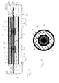
- FIG. 1 shows a vertical section through the longitudinal axis of a conduit with heat insulation, as prepared according to the present invention. Furthermore, a preferred embodiment of the device for carrying out the method is shown schematically in the figure. The process becomes discontinuous worked, ie there are produced in the foaming stationary held individual tubes of defined length.
- the conduit 1 in this case has an outer tube 2, which is usually made of plastic, e.g. made of polyethylene.
- an inner tube 3 is arranged, wherein the diameter of the inner tube is significantly smaller than the diameter of the outer tube, so that between the inner wall 7 of the outer tube 2 and the outer wall 6 of the inner tube 3 in the production of the conduit initially a cavity. 4 which is filled during manufacture with an insulating foam, eg a polyurethane foam, so that at the end of the foaming of the cavity 4 is filled with the insulating material 14. This cures and then forms not only the heat insulation layer but also the fixation of the inner tube 3 in the outer tube 2.
- an insulating foam eg a polyurethane foam
- the inner tube 3 To produce such a conduit 1, the inner tube 3 must be positioned in the outer tube 2 and held in place during foaming. It is essential for ensuring homogeneous insulation properties of the finished conduit along its length that the inner tube is as straight as possible, so that the cavity has the most uniform shape possible.
- the retention in a straight shape of the inner tube 3 takes place in that a tensile force is exerted in the longitudinal direction of the tubes.
- the inner tube 3 itself or preferably a separate tension member 10 of which the inner tube is held, so tense that it is substantially rectilinear and not sagging.
- the exercise of a tensile force on the inner tube 3 itself is especially in question when the inner tube 3 is made of metal.
- the inner tube is also a plastic tube, for example an inner tube made of ABS (acrylonitrile-butadiene acrylate).
- a separate tension member is used, on which the inner tube is supported.
- the tension member may be arranged outside the inner tube, and be, for example, a metal band, which can be stretched straight, and on which the inner tube is supported. This band then remains after foaming in the conduit 1.
- the preferred solution is formed by a tension member 10 which extends in the inner tube and thereby can be removed from the inner tube after the foaming process or the curing of the foam.
- the tension member 10 is formed by a rope, in particular a steel cable.
- the elements can be fixedly arranged on the rope. Preferably, however, they include the rope so that they are displaceable on this.
- the mutual spacing of the centering elements is preferably determined by spacers 18 which connect the elements, in particular the centering elements.
- spacers 18 may also be provided to the covers 4 and 5, which close the front side of the tube in the manufacture, to allow the foaming.
- the already mentioned foam lance is then inserted through at least one opening 19 in one of the lids in the cavity 4, so that it can be foamed.
- the foam lance is introduced from the opening 19 forth to the opposite lid 4 and gradually withdrawn during the discharge of the foam from the lance in the direction of the lid 5 until the entire cavity is filled with foaming material.
- the inner tube 3 is held straight on the tensioned by tension member 10 and held by this also, so that it can not be moved by the foaming pressure.
- the outer tube 2 is also preferably retained. which lies in the illustrated device on the bed 21 of a pipe receptacle 20, not shown in detail.
- the outer tube 2 is preferably fixed by not shown means to the tube receiving in its position so that it can not be moved by the foaming.
- the tensile force on the tension member 10 is generated by any means that may be parts of the pipe receiving or separate means. For example, this can be done as shown, characterized in that the tension member 10 is fixed on one side in a device fixed block 9 'and on the other side in a direction of arrow B (and also in the opposite direction) driven movable block 9 is fixed.
- the drive in the direction of arrow B for tensioning the tension member 10 can be done hydraulically, pneumatically or by electric motor or possibly also manually by a drive means 29 known to those skilled in the art.
- a rope as a tension member to its clamping in the blocks 9 'and 9 corresponding cable sleeves 12, 14 with fastening means 13 and 15, e.g.
- Threads be provided to releasably attach the tension member to the means, or to the elements 9, 9 ', for exerting the tensile force.
- the tension member for removing the finished conduit from the device can be easily solved from the tension elements 9 'and 9, when the block 9 is moved back in the opposite direction to the arrow B and thereby the traction means is relieved again.
- the lid 4 and 5 are removed and the tension member 10 is pulled out of the inner tube 3 of the conduit 1.
- the centering elements 16 and 17 or the other centering elements can be provided on its contact surface to the inside of the inner tube 3 with a sliding-resistant coating or with rolling elements to facilitate the extraction of the tension member from the inner tube.
- Such embodiments of the centering elements 16, 17 also facilitate the insertion of the tension member in the Inner tube 3. This process is at the beginning of the production of the conduit 1.
- the outer tube 2 can be pushed over the inner tube 3.
- Such a unit of outer tube 2 and inner tube 3 with the tension member 10 is then arranged in the device as shown by the tension member 10 is attached to the tension elements 9 'and 9. Further, the outer tube is positioned or the tube receiving the bed 21 between the tension members 9 'and 9 is placed so that the outer tube rests on the bed 21.
- the procedure is usually such that the tensile force is exerted on the tension member 10 by the drive of at least one of the tension elements, so that this tensioned and runs completely straight between the elements or tension blocks 9 'and 9.
- the inner tube 3 which is supported on the tension member and is held by this, a virtually completely rectilinear course.
- the inner tube 3 is thus fixed in position by the tension member, as this positionally fixed between the elements 9, 9 'is fixed.
- the outer tube 2 By moving and lifting the bed 21 by means of only indicated drives 28, ie in particular in the direction of the arrows A, and preferably also in the direction perpendicular to these arrows and perpendicular to the plane, the outer tube 2 can be positioned to the straight running and positionally fixed inner tube 3 so that the cavity 4 is formed in the desired manner. As a rule, the positioning is carried out so that the cavity has a uniform, annular shape.
- the method also allows in a simple manner, an eccentric arrangement of the inner tube 3 in the outer tube 2.
- a plurality of inner tubes with spacing from each other or adjacent to each other by means of one or more tension members according to the invention can be kept just stretched. If the positioning is completed, then the mentioned Way with the Shuumlanze the insulating foam introduced into the cavity.
- the inner tube In stationary, discontinuous production of heat-insulated pipes with an inner tube and an outer tube and an intervening foamed insulation, the inner tube can be placed on a tension member. This is tensioned by tension between clamping means, so that it runs straight, whereby the inner tube is held straight. In this straight held shape, the inner tube can be foamed in the outer tube, without spacers between the tubes are needed.
Landscapes
- Engineering & Computer Science (AREA)
- Mechanical Engineering (AREA)
- General Engineering & Computer Science (AREA)
- Thermal Insulation (AREA)
Abstract
Description
- Die Erfindung betrifft ein Verfahren zur diskontinuierlichen Herstellung eines wärmeisolierten Leitungsrohrs, umfassend das Positionieren mindestens eines Innenrohrs in einem Aussenrohr unter Bildung eines Hohlraums zwischen der Aussenwandung des Innenrohrs und der Innenwandung des Aussenrohrs sowie das Ausschäumen des Hohlraums. Ferner betrifft die Erfindung eine Vorrichtung zur Herstellung derartiger Leitungsrohre.
- Die Herstellung der eingangs genannten Leitungsrohre erfolgt dadurch, dass das Innenrohr mittels im fertigen Leitungsrohr verbleibenden Abstandselementen aus Kunststoff im Aussenrohr positioniert wird. Dabei ist die Anordnung der Abstandselemente aufwendig und diese bilden im fertigen Leitungsrohr unerwünschte Wärme- bzw. Kältebrücken. Die Positionierung des Innenrohrs ist zudem nur bei den Abstandselementen genau eingehalten. Das Innenrohr kann vor dem Schäumen zwischen den Abstandselementen mehr oder weniger durchhängen, was nur durch eine grössere Zahl von Abstandselementen vermieden werden kann. Das Ausschäumen des Hohlraums erfolgt mit einer langen Schäumlanze, welche von einem ersten Ende in den Hohlraum zwischen Innen- und Aussenrohr eingeführt und bis zum verschlossenen zweiten Ende vorgeschoben wird. Dann wird durch die Lanze das aufschäumende Isolationsmaterial eingebracht, wobei die Lanze zum ersten Ende hin zurückgezogen wird, bis der ganze Hohlraum möglichst gleichmässig mit Isolierschaum gefüllt ist. Dabei sind die Abstandselemente so geformt und angeordnet, dass sie die Lanze möglichst nicht behindern, doch wird das Einbringen der Isolation dennoch durch die Abstandselemente erschwert.
- Der Erfindung liegt die Aufgabe zu Grunde, ein Verfahren zu schaffen, welches die genannten Nachteile vermeidet.
- Dies wird bei dem eingangs genannten Verfahren dadurch erzielt, dass das Innenrohr durch Zugkraft in Längsrichtung der Rohre im Wesentlichen gerade gehalten und derart gehalten umschäumt wird.
- Es hat sich gezeigt, dass das Innenrohr durch eine Zugkraft derart gerade gehalten werden kann, dass es im Aussenrohr auch ohne Abstandselemente gerade verlaufend gehalten werden kann. Damit entfallen die genannten Nachteile.
- Die gerade Form des Innenrohrs kann durch Zugkraft auf das Rohr selber bewirkt werden, was insbesondere bei Innenrohren aus Metall vorgesehen sein kann. In einer bevorzugten Ausführungsart wird indes die Zugkraft nicht an dem Innenrohr selber angelegt, sondern an einem Zugglied, auf welches sich das Innenrohr abstützt. Vorzugsweise verläuft das Zugglied dabei im Innenrohr. Das Zugglied kann bevorzugt als Seil, insbesondere Stahlseil, ausgeführt sein, welches zudem Elemente tragen kann, die zur Abstützung des Innenrohrs am Seil dienen und insbesondere zur Zentrierung des Innenrohrs zu dem Seil.
- Das Innenrohr muss jedenfalls beim Herstellungsschritt des Umschäumens des Innenrohrs bzw. der Ausschäumung des Hohlraums gerade gehalten werden. Das Innenrohr wird aber bevorzugt bereits beim vorgängigen Schritt der Positionierung im Aussenrohr durch die Zugkraft gerade gehalten. Zur Positionierung kann dann die Lage des Aussenrohrs zu dem gerade gehaltenen Innenrohr eingestellt werden, das dabei lagefest gehalten wird. In einer anderen Variante wird das Innenrohr auch im noch nicht gerade gezogenen Zustand lediglich mit seinen Enden in die gewünschte Lage relativ zum Aussenrohr gebracht, worauf erst dann das Innenrohr durch die Zugkraft für das Schäumen in die gerade Form gebracht wird.
- Bei einer bevorzugten Ausführung wird zunächst das Innenrohr auf die Elemente des Zugglieds aufgeschoben bzw. das Zugglied durch das Innenrohr gezogen. Danach wird das Innenrohr samt Zugglied in das Aussenrohr eingebracht. Mittels des Zuggliedes wird dann das Innenrohr in die völlig gerade verlaufende Form gebracht, indem die Zugkraft an den Enden des Zuggliedes aufgebracht und dieses gerade gespannt wird, worauf die Positionierung zur Bildung des definierten Hohlraums erfolgt, indem das Aussenrohr in seiner Lage verändert wird, bis die gewünschte Position zum lagefesten Innenrohr gegeben ist.
- Der Erfindung liegt weiter die Aufgabe zu Grunde eine Vorrichtung zur Herstellung von wärmeisolierten Leitungsrohren zu schaffen, bei welcher die genannten Nachteile nicht auftreten.
- Diese Aufgabe wird mit einer Vorrichtung gemäss Anspruch 8 gelöst.
- Im Folgenden werden Ausführungsbeispiele der Erfindung anhand der Zeichnungen näher erläutert. Dabei zeigt
-
Figur 1 eine Vertikalschnittansicht durch ein Leitungsrohr in Längsrichtung sowie die schematisch Vorrichtung zu seiner Herstellung; und -
Figur 2 eine Vertikalschnittansicht durch das Leitungsrohr in Querrichtung. -
Figur 1 zeigt einen vertikalen Schnitt durch die Längsachse eines Leitungsrohrs mit Wärmeisolierung, wie es gemäss der vorliegenden Erfindung hergestellt wird. Weiter ist in der Figur schematisch eine bevorzugte Ausführungsform der Vorrichtung zur Durchführung des Verfahrens dargestellt. Bei dem Verfahren wird diskontinuierlich gearbeitet, d.h. es werden bei der Schäumung stationär gehaltene einzelne Rohre definierter Länge hergestellt. - Das Leitungsrohr 1 weist dabei ein Aussenrohr 2 auf, welches in der Regel aus Kunststoff besteht, z.B. aus Polyethylen. In dem Aussenrohr ist ein Innenrohr 3 angeordnet, wobei der Durchmesser des Innenrohr deutlich geringer ist, als der Durchmesser des Aussenrohrs, so dass sich zwischen der Innenwandung 7 des Aussenrohrs 2 und der Aussenwandung 6 des Innenrohrs 3 bei der Herstellung des Leitungsrohrs zunächst ein Hohlraum 4 befindet, welcher während der Herstellung mit einem Isolierschaum ausgefüllt wird, z.B. einem Polyurethanschaum, so dass am Ende des Ausschäumens der Hohlraum 4 mit dem Isolationsmaterial 14 gefüllt ist. Dies härtet aus und bildet dann neben der Wärmeisolationsschicht auch die Fixierung des Innenrohrs 3 im Aussenrohr 2.
- Zur Herstellung eines solchen Leitungsrohrs 1 muss das Innenrohr 3 im Aussenrohr 2 positioniert und während des Schäumens festgehalten werden. Dabei ist es für die Sicherstellung homogener Isolationseigenschaften des fertigen Leitungsrohrs entlang seiner Länge wesentlich, dass das Innenrohr möglichst geradlinig verläuft, damit der Hohlraum möglichst gleichmässige Form aufweist.
- Gemäss der Erfindung erfolgt das Festhalten in gerader Form des Innenrohrs 3 dadurch, dass eine Zugkraft in Längsrichtung der Rohre ausgeübt wird. Durch diese Zugkraft wird das Innenrohr 3 selber oder bevorzugterweise ein separates Zugglied 10 von dem das Innenrohr gehalten ist, so gespannt, dass es im Wesentlichen geradlinig und nicht durchhängend verläuft. Die Ausübung einer Zugkraft auf das Innenrohr 3 selber kommt vor allem in Frage, wenn das Innenrohr 3 aus Metall besteht. Bevorzugterweise ist indes auch das Innenrohr ein Kunststoffrohr, z.B. ein Innenrohr aus ABS (Acrylnitrilbutadienacrylat). In diesem Fall könnte durch das Anlegen einer Zugkraft in Längsrichtung des Innenrohres an das Rohr selber eine Längung des Rohres erfolgen, was nicht gewünscht ist. Bevorzugt wird daher ein separates Zugglied eingesetzt, an welchem sich das Innenrohr abstützt. Das Zugglied kann ausserhalb des Innenrohrs angeordnet sein, und z.B. ein Metallband sein, welches gerade verlaufende gespannt werden kann, und auf welchem sich das Innenrohr abstützt. Dieses Band verbleibt dann nach der Schäumung im Leitungsrohr 1. Die bevorzugte Lösung wird allerdings von einem Zugglied 10 gebildet, welches im Innenrohr verläuft und dadurch nach dem Schäumvorgang bzw. dem Aushärten des Schaumes aus dem Innenrohr entnommen werden kann.
- In
Figur 1 ist ein Beispiel dargestellt, bei welchem das Zugglied 10 von einem Seil gebildet ist, insbesondere von einem Stahlseil. Entlang dieses Seiles sind bevorzugt Elemente, hier die Zentrierelemente 16, 17, angeordnet, welche das Rohr halten bzw. abstützen. Die Elemente können fest an dem Seil angeordnet sein. Bevorzugterweise umfassen sie das Seil aber so, dass sie auf diesem verschiebbar sind. Der gegenseitige Abstand der Zentrierelemente wird bevorzugt durch Abstandshalter 18 bestimmt, welche die Elemente, insbesondere die Zentrierelemente, verbinden. Solche Abstandshalter 18 können auch zu den Deckeln 4 und 5 hin vorgesehen sein, welche bei der Herstellung das Rohr stirnseitig verschliessen, um die Schäumung zu ermöglichen. Die bereits erwähnte Schaumlanze wird dann durch mindestens eine Öffnung 19 in einem der Deckel in den Hohlraum 4 eingeführt, damit dieser ausgeschäumt werden kann. Dazu wird die Schaumlanze von der Öffnung 19 her bis zum gegenüberliegenden Deckel 4 eingeführt und während des Austritts des Schaums aus der Lanze nach und nach in Richtung des Deckels 5 zurückgezogen, bis der gesamte Hohlraum mit aufschäumendem Material gefüllt ist. Während dieses Vorganges ist das Innenrohr 3 auf dem durch Zugkraft gespanntem Zugglied 10 gerade gehalten und durch dieses auch festgehalten, so dass es durch den Schäumdruck nicht verschoben werden kann. Festgehalten wird bevorzugt auch das Aussenrohr 2, welches in der dargestellten Vorrichtung auf dem Bett 21 einer nicht im Detail dargestellten Rohraufnahme 20 liegt. Das Aussenrohr 2 wird dabei bevorzugt durch nicht dargestellte Mittel an der Rohraufnahme in seiner Lage fixiert, damit es durch den Schäumdruck nicht verschoben werden kann. - Die Zugkraft auf das Zugglied 10 wird durch beliebige Mittel erzeugt, die Teile der Rohraufnahme sein können oder separate Mittel. Zum Beispiel kann dies wie dargestellt dadurch erfolgen, dass das Zugglied 10 einseitig in einem vorrichtungsfesten Block 9' fixiert ist und auf der anderen Seite in einem in Richtung des Pfeiles B (und auch in Gegenrichtung) angetrieben bewegbaren Block 9 fixiert ist. Der Antrieb in Richtung des Pfeiles B zur Spannung des Zuggliedes 10 kann hydraulisch, pneumatisch oder elektromotorisch oder gegebenenfalls auch händisch durch ein dem Fachmann bekanntes Antriebsmittel 29 erfolgen. Im Falle eines Seils als Zugglied können zu dessen Einspannung in den Blöcken 9' und 9 entsprechende Seilmuffen 12, 14 mit Befestigungsmitteln 13 und 15, z.B. Gewinden, vorgesehen sein, um das Zugglied lösbar an den Mitteln, bzw. an den Elementen 9, 9', zur Ausübung der Zugkraft zu befestigen. Dadurch kann das Zugglied zur Entnahme des fertigen Leitungsrohres aus der Vorrichtung einfach aus den Zugelementen 9' und 9 gelöst werden, wenn der Block 9 in Gegenrichtung zum Pfeil B zurück gefahren wird und dadurch das Zugmittel wieder entlastet wird. Danach werden die Deckel 4 und 5 entfernt und das Zugglied 10 wird aus dem Innenrohr 3 des Leitungsrohres 1 herausgezogen. Die Zentrierelemente 16 und 17 bzw. die weiteren Zentrierelemente können dazu an ihrer Kontaktfläche zu der Innenseite des Innenrohrs 3 mit einer gleithemmenden Beschichtung oder mit Wälzkörpern versehen sein, um das Herausziehen des Zuggliedes aus dem Innenrohr zu erleichtern.
- Solche Ausführungen der Zentrierelemente 16, 17 erleichtern auch das Einführen des Zuggliedes in das Innenrohr 3. Dieser Vorgang steht am Anfang der Herstellung des Leitungsrohres 1. In einem vorangehenden Schritt oder in einem nachfolgenden Schritt kann das Aussenrohr 2 über das Innenrohr 3 geschoben werden. Eine solche Einheit aus Aussenrohr 2 und Innenrohr 3 mit dem Zugglied 10 wird dann in der Vorrichtung wie gezeigt angeordnet, indem das Zugglied 10 an den Zugelementen 9' und 9 befestigt wird. Ferner wird das Aussenrohr so positioniert bzw. die Rohraufnahme mit dem Bett 21 zwischen den Zugelementen 9' und 9 wird so platziert, dass das Aussenrohr auf dem Bett 21 aufliegt. Danach wird in der Regel so vorgegangen, dass durch den Antrieb mindestens eines der Zugelemente die Zugkraft auf das Zugglied 10 ausgeübt wird, damit sich dieses spannt und völlig gerade zwischen den Elementen bzw. Zugblöcken 9' und 9 verläuft. Mit genügender Spannung des Zuggliedes 10 die zu dessen geradem Verlauf führt, weist dann auch das Innenrohr 3, welches auf dem Zugglied abgestützt ist bzw. von diesem gehalten ist, einen praktisch völlig geradlinigen Verlauf auf. Zudem ist das Innenrohr 3 damit durch das Zugglied lagefest positioniert, da dieses lagefest zwischen den Elementen 9, 9' fixiert ist. Durch ein Verschieben und Heben des Betts 21 mittels nur angedeuteter Antriebe 28, also insbesondere in Richtung der Pfeile A, sowie vorzugsweise auch in Richtung senkrecht zu diesen Pfeilen und senkrecht zur Zeichnungsebene, kann das Aussenrohr 2 zu dem gerade verlaufenden und lagefesten Innenrohr 3 positioniert werden, so dass der Hohlraum 4 auf die gewünschte Weise gebildet ist. In der Regel erfolgt die Positionierung dabei so, dass der Hohlraum eine gleichmässige, ringförmige Form hat. Das Verfahren erlaubt aber auf einfache Weise auch eine aussermittige Anordnung des Innenrohrs 3 im Aussenrohr 2. Auch können auf einfache Weise mehrere Innenrohre mit Abstand voneinander oder aneinander anliegend mittels einem oder mehreren Zuggliedern gemäss der Erfindung gerade gespannt gehalten werden. Ist die Positionierung abgeschlossen, so wird auf die erwähnte Weise mit der Schäumlanze der Isolierschaum in den Hohlraum eingebracht.
- Bei stationären, diskontinuierlichen Herstellung von wärmeisolierten Leitungsrohren mit einem Innenrohr und einem Aussenrohr und einer dazwischen liegenden geschäumten Isolation kann das Innenrohr auf einem Zugglied platziert werden. Dieses wird durch Zugkraft zwischen Spannmitteln gespannt, so dass es gerade verläuft, wodurch auch das Innenrohr gerade gehalten ist. In dieser gerade gehaltenen Form kann das Innenrohr im Aussenrohr umschäumt werden, ohne dass Abstandshalter zwischen den Rohren benötigt werden.
Claims (11)
- Verfahren zur Herstellung eines wärmeisolierten Leitungsrohrs (1), umfassend das Positionieren mindestens eines Innenrohrs (3) in einem Aussenrohr (2) unter Bildung eines Hohlraums (4) zwischen der Aussenwandung (6) des Innenrohrs (3) und der Innenwandung (7) des Aussenrohrs (2) sowie das Ausschäumen des Hohlraums (4), dadurch gekennzeichnet, dass das Innenrohr (2) durch Zugkraft in Längsrichtung der Rohre im Wesentlichen gerade verlaufend gehalten und derart gehalten umschäumt wird.
- Verfahren nach Anspruch 1, dadurch gekennzeichnet, dass das Innenrohr bei der Positionierung gerade gehalten wird.
- Verfahren nach Anspruch 1 oder 2, dadurch gekennzeichnet, dass die Zugkraft auf das Innenrohr ausgeübt wird.
- Verfahren nach Anspruch 1 oder 2, dadurch gekennzeichnet, dass die Zugkraft auf ein Zugglied (10) ausgeübt wird, welches dadurch gerade verlaufend gespannt wird, wodurch das mit dem Zugglied in Verbindung stehende Innenrohr die gerade verlaufende Form erhält.
- Verfahren nach Anspruch 4, dadurch gekennzeichnet, dass das Zugglied im Innern des Innenrohrs verlaufend angeordnet wird und nach der Umschäumung aus dem Innerohr entfernt wird.
- Verfahren nach Anspruch 5, dadurch gekennzeichnet, dass das Zugglied (10) ein Seil (11) und mehrere Zentrierelemente (16, 17) zur Abstützung des Innenrohrs aufweist.
- Verfahren nach einem der Ansprüche 4 bis 6, gekennzeichnet durch die Schritte des Aufschiebens des Innenrohrs auf das Zugglied oder des Einziehens des Zugglieds in das Innenrohr, des Einbringens des Innenrohrs samt dem Zugglied in das Aussenrohr, des Spannens des Zugglieds durch Aufbringen der Zugkraft und der Positionierung von Aussen- und Innenrohr zur Bildung des definierten Hohlraums durch Lageveränderung des Aussenrohrs.
- Vorrichtung zur Herstellung von wärmeisolierten Leitungsrohren (1), welche jeweils ein Aussenrohr (2), mindestens ein Innenrohr (3) sowie eine den Raum zwischen Innenrohr und Aussenrohr ausfüllende geschäumte Isolation (14) aufweisen, dadurch gekennzeichnet, dass die Vorrichtung eine sich in Längsrichtung der herzustellenden Rohre erstreckende Rohraufnahme (20, 21), beidseits der Längsenden der Rohraufnahme angeordnete Spannmittel (9, 9') sowie mindestens ein die Spannmittel lösbar verbindendes Zugglied (10) aufweist, wobei die Spannmittel einen Antrieb (29) umfassen, durch welchen eine einstellbare Zugkraft auf das Zugglied ausübbar ist, und wobei das Zugglied zur mindestens abschnittsweisen Abstützung eines Rohrs entlang seiner Längserstreckung ausgebildet ist.
- Vorrichtung nach Anspruch 8, dadurch gekennzeichnet, dass das Zugglied (10) von einem Stahlseil (11) gebildet ist, welches entlang seiner Längserstreckung mehrere für das Innenrohr bestimmte Zentrierelemente (16, 17) aufweist.
- Vorrichtung nach Anspruch 9, dadurch gekennzeichnet, dass die Zentrierelemente durch koaxial zum Stahlseil verlaufende Abstandshalter (18) voneinander beabstandet sind.
- Vorrichtung nach einem der Ansprüche 8 bis 10, dadurch gekennzeichnet, dass die Rohraufnahme eine für das Aussenrohr bestimmte Auflage (21) aufweist, welche in ihrer Position relativ zu dem Zugglied einstellbar ist.
Priority Applications (7)
| Application Number | Priority Date | Filing Date | Title |
|---|---|---|---|
| EP09006098.9A EP2248648B1 (de) | 2009-05-05 | 2009-05-05 | Verfahren und Vorrichtung zur Herstellung eines wärmeisolierten Leitungsrohrs |
| DK09006098.9T DK2248648T3 (en) | 2009-05-05 | 2009-05-05 | A method and apparatus for the manufacture of a heat-insulated pipe |
| PT09006098T PT2248648E (pt) | 2009-05-05 | 2009-05-05 | Método e dispositivo para a produção de uma conduta termicamente isolada |
| PL09006098T PL2248648T3 (pl) | 2009-05-05 | 2009-05-05 | Sposób i urządzenie do wytwarzania izolowanej cieplnie rury przewodowej |
| ES09006098.9T ES2568044T3 (es) | 2009-05-05 | 2009-05-05 | Procedimiento y dispositivo para la fabricación de una tubería aislada térmicamente |
| US12/921,939 US8950071B2 (en) | 2009-05-05 | 2010-05-05 | Method and device for manufacturing a heat-insulated pipe |
| PCT/CH2010/000118 WO2010127463A1 (de) | 2009-05-05 | 2010-05-05 | Verfahren und vorrichtung zur herstellung eines wärmeisolierten leitungsrohrs |
Applications Claiming Priority (1)
| Application Number | Priority Date | Filing Date | Title |
|---|---|---|---|
| EP09006098.9A EP2248648B1 (de) | 2009-05-05 | 2009-05-05 | Verfahren und Vorrichtung zur Herstellung eines wärmeisolierten Leitungsrohrs |
Publications (2)
| Publication Number | Publication Date |
|---|---|
| EP2248648A1 true EP2248648A1 (de) | 2010-11-10 |
| EP2248648B1 EP2248648B1 (de) | 2016-03-30 |
Family
ID=41168534
Family Applications (1)
| Application Number | Title | Priority Date | Filing Date |
|---|---|---|---|
| EP09006098.9A Active EP2248648B1 (de) | 2009-05-05 | 2009-05-05 | Verfahren und Vorrichtung zur Herstellung eines wärmeisolierten Leitungsrohrs |
Country Status (7)
| Country | Link |
|---|---|
| US (1) | US8950071B2 (de) |
| EP (1) | EP2248648B1 (de) |
| DK (1) | DK2248648T3 (de) |
| ES (1) | ES2568044T3 (de) |
| PL (1) | PL2248648T3 (de) |
| PT (1) | PT2248648E (de) |
| WO (1) | WO2010127463A1 (de) |
Cited By (6)
| Publication number | Priority date | Publication date | Assignee | Title |
|---|---|---|---|---|
| CN103028928A (zh) * | 2012-12-28 | 2013-04-10 | 江苏大学 | 一种装配双层保温螺旋风管的装置 |
| WO2016127267A1 (de) | 2015-02-11 | 2016-08-18 | Brugg Rohr Ag Holding | Leitungsrohr mit thermischer dämmung |
| WO2018015216A1 (de) | 2016-07-20 | 2018-01-25 | Brugg Rohr Ag Holding | Thermisch gedämmte mediumrohre mit hfo-haltigem zellgas |
| CN109333407A (zh) * | 2018-11-22 | 2019-02-15 | 中国化学工程第三建设有限公司 | 管道支撑工具 |
| DE202017007631U1 (de) | 2016-07-20 | 2023-10-27 | Brugg Rohr Ag Holding | Thermisch gedämmte Mediumrohre mit HFO - haltigem Zellgas |
| EP3247951B1 (de) * | 2014-12-23 | 2025-09-24 | BetterPipe Finland Oy | Verfahren zur herstellung eines isolierten luftkanals und isolierter luftkanal |
Families Citing this family (9)
| Publication number | Priority date | Publication date | Assignee | Title |
|---|---|---|---|---|
| US8667995B1 (en) | 2012-05-23 | 2014-03-11 | Carl Fanelli | Insulated ducts and insulated ductworks |
| CN103634956A (zh) * | 2013-09-05 | 2014-03-12 | 史大涌 | 内置式伴热管 |
| CN105855897B (zh) * | 2016-05-04 | 2018-06-01 | 海门名驰工业设计有限公司 | 电加热棒组装机 |
| US10960588B2 (en) | 2016-06-08 | 2021-03-30 | Bayou Holdco, Inc. | System and method for applying moldable material to a pipe |
| US10357907B2 (en) | 2016-06-08 | 2019-07-23 | Bayou Holdco, Inc. | System and method for applying moldable material to a pipe by injecting moldable material from a movable support |
| US10737309B2 (en) | 2018-03-09 | 2020-08-11 | GF Urecon Ltd. | Apparatus and method for manufacturing insulated pipe assembly |
| CN110421774B (zh) * | 2018-05-06 | 2023-11-10 | 内蒙古君诚兴业管道有限责任公司 | 一种在线自动同心度穿管封堵装置及自动发泡生产线 |
| US11999089B2 (en) | 2020-10-20 | 2024-06-04 | Bayou Holdco, Inc. | Transportable molding system for forming insulation on long pipes and related methods |
| BR102021024567A2 (pt) | 2020-12-04 | 2022-06-07 | Bayou Holdco, Inc. | Sistema de moldagem para tubo isolado |
Citations (4)
| Publication number | Priority date | Publication date | Assignee | Title |
|---|---|---|---|---|
| GB344356A (en) * | 1929-12-03 | 1931-03-03 | William Horace Grint | Improvements in or relating to supports for tubular mandrels |
| EP0897788A1 (de) | 1996-07-23 | 1999-02-24 | BRUGG Rohrsysteme GmbH | Verfahren zur Herstellung eines wärmeisolierten Leitungsrohres |
| WO2000047387A1 (de) * | 1999-02-09 | 2000-08-17 | Bayer Aktiengesellschaft | Verfahren und vorrichtung zum diskontinuierlichen herstellen von wärmegedämmten rohren |
| WO2005058573A1 (en) | 2003-12-18 | 2005-06-30 | Socotherm S.P.A. | Method for manufacturing and heat-insulated pipes for conveying hot or cold fluids |
Family Cites Families (19)
| Publication number | Priority date | Publication date | Assignee | Title |
|---|---|---|---|---|
| US2634759A (en) * | 1949-07-27 | 1953-04-14 | William Twickler & Sons Inc | Insulated flue pipe |
| US3693665A (en) * | 1970-01-28 | 1972-09-26 | Shell Oil Co | Pipeline for the transport of cold liquids |
| US4538337A (en) * | 1982-08-31 | 1985-09-03 | The Babcock & Wilcox Company | Method of mechanically prestressing a tubular apparatus |
| US4793404A (en) * | 1984-12-21 | 1988-12-27 | Ryosuke Hata | Composite pipe, process for producing the same, and heat pipe using of the same |
| CA2003295C (en) * | 1988-12-09 | 1995-07-04 | Yoshihisa Ohashi | Process for manufacturing clad metal tubing |
| US5628345A (en) * | 1994-06-22 | 1997-05-13 | American Pipeline Supply, Corp. | Point repair system for conduits |
| US6199595B1 (en) * | 1998-06-04 | 2001-03-13 | Jerry G. Baker | Insulated marine pipe apparatus and method of installation |
| US6382259B1 (en) * | 1998-06-22 | 2002-05-07 | Corus Uk Limited | Insulated pipework systems |
| GB9917733D0 (en) * | 1999-07-28 | 1999-09-29 | Kvaerner Earl & Wright | Thermal insulated pipelines |
| GB2376728A (en) * | 2001-06-20 | 2002-12-24 | Corus Uk Ltd | A method of manufacturing a double-walled pipe structure |
| DE10261402A1 (de) * | 2002-12-30 | 2004-07-15 | Schulz-Harder, Jürgen, Dr.-Ing. | Wärmesenke in Form einer Heat-Pipe sowie Verfahren zum Herstellen einer solchen Wärmesenke |
| FR2852677B1 (fr) * | 2003-03-18 | 2006-01-06 | Saipem Sa | Dispositif de rechauffage et d'isolation thermique d'au moins une conduite sous-marine |
| US8141218B2 (en) * | 2005-01-14 | 2012-03-27 | Cornelis Van Zandwijk | Method for manufacturing a double walled pipeline |
| US7451541B2 (en) * | 2005-02-04 | 2008-11-18 | Pratt & Whitney Canada Corp. | Method of heat shielding an inner tube |
| US7156128B1 (en) * | 2005-06-21 | 2007-01-02 | Kanaflex Corporation | Synthetic resin pipe |
| US7699078B1 (en) * | 2006-02-16 | 2010-04-20 | Husmann Jr Jackie | Thermally insulated ductwork and method of manufacture |
| FR2918149B1 (fr) * | 2007-06-29 | 2009-09-25 | Inst Francais Du Petrole | Conduite renforcee a deux enveloppes et methode de fabrication. |
| US8397765B2 (en) * | 2008-07-25 | 2013-03-19 | Shawcor Ltd. | High temperature resistant insulation for pipe |
| US9500302B2 (en) * | 2011-08-23 | 2016-11-22 | Koninklijke Philips N.V. | Method for attenuating noise produced by pipes and pipe arrangement |
-
2009
- 2009-05-05 PL PL09006098T patent/PL2248648T3/pl unknown
- 2009-05-05 DK DK09006098.9T patent/DK2248648T3/en active
- 2009-05-05 PT PT09006098T patent/PT2248648E/pt unknown
- 2009-05-05 ES ES09006098.9T patent/ES2568044T3/es active Active
- 2009-05-05 EP EP09006098.9A patent/EP2248648B1/de active Active
-
2010
- 2010-05-05 WO PCT/CH2010/000118 patent/WO2010127463A1/de not_active Ceased
- 2010-05-05 US US12/921,939 patent/US8950071B2/en active Active
Patent Citations (5)
| Publication number | Priority date | Publication date | Assignee | Title |
|---|---|---|---|---|
| GB344356A (en) * | 1929-12-03 | 1931-03-03 | William Horace Grint | Improvements in or relating to supports for tubular mandrels |
| EP0897788A1 (de) | 1996-07-23 | 1999-02-24 | BRUGG Rohrsysteme GmbH | Verfahren zur Herstellung eines wärmeisolierten Leitungsrohres |
| WO2000047387A1 (de) * | 1999-02-09 | 2000-08-17 | Bayer Aktiengesellschaft | Verfahren und vorrichtung zum diskontinuierlichen herstellen von wärmegedämmten rohren |
| WO2005058573A1 (en) | 2003-12-18 | 2005-06-30 | Socotherm S.P.A. | Method for manufacturing and heat-insulated pipes for conveying hot or cold fluids |
| EP1699611B1 (de) * | 2003-12-18 | 2008-01-09 | SOCOTHERM S.p.A. | Verfahren zur herstellung von wärmeisolierten rohren und entsprechende rohre zur beförderung von heissen und kalten fluiden |
Non-Patent Citations (1)
| Title |
|---|
| "KETTENLINIE (MATHEMATIK)", WIKIPEDIA, DER FREIEN ENZYKLOPÄDIE, 4 June 2014 (2014-06-04), pages 1 - 3, XP003035175, Retrieved from the Internet <URL:HTTP://DE.WIKIPEDIA.ORG/WIKI/KETTENLINIE_%28MATHEMATIK%29> |
Cited By (10)
| Publication number | Priority date | Publication date | Assignee | Title |
|---|---|---|---|---|
| CN103028928A (zh) * | 2012-12-28 | 2013-04-10 | 江苏大学 | 一种装配双层保温螺旋风管的装置 |
| CN103028928B (zh) * | 2012-12-28 | 2015-06-24 | 江苏大学 | 一种装配双层保温螺旋风管的装置 |
| EP3247951B1 (de) * | 2014-12-23 | 2025-09-24 | BetterPipe Finland Oy | Verfahren zur herstellung eines isolierten luftkanals und isolierter luftkanal |
| WO2016127267A1 (de) | 2015-02-11 | 2016-08-18 | Brugg Rohr Ag Holding | Leitungsrohr mit thermischer dämmung |
| WO2018015216A1 (de) | 2016-07-20 | 2018-01-25 | Brugg Rohr Ag Holding | Thermisch gedämmte mediumrohre mit hfo-haltigem zellgas |
| EP3584070A1 (de) | 2016-07-20 | 2019-12-25 | Brugg Rohr Ag Holding | Thermisch gedämmte mediumrohre mit hfo haltigem zellgas |
| US11493163B2 (en) | 2016-07-20 | 2022-11-08 | Brugg Rohr Ag Holding | Thermally insulated medium pipes having HFO-containing cell gas |
| DE202017007631U1 (de) | 2016-07-20 | 2023-10-27 | Brugg Rohr Ag Holding | Thermisch gedämmte Mediumrohre mit HFO - haltigem Zellgas |
| EP4446370A2 (de) | 2016-07-20 | 2024-10-16 | Brugg Rohr AG Holding | Thermisch gedämmte mediumrohre mit hfo-haltigem zellgas |
| CN109333407A (zh) * | 2018-11-22 | 2019-02-15 | 中国化学工程第三建设有限公司 | 管道支撑工具 |
Also Published As
| Publication number | Publication date |
|---|---|
| US20110047774A1 (en) | 2011-03-03 |
| DK2248648T3 (en) | 2016-07-04 |
| ES2568044T3 (es) | 2016-04-27 |
| WO2010127463A1 (de) | 2010-11-11 |
| US8950071B2 (en) | 2015-02-10 |
| PL2248648T3 (pl) | 2017-08-31 |
| PT2248648E (pt) | 2016-06-03 |
| EP2248648B1 (de) | 2016-03-30 |
Similar Documents
| Publication | Publication Date | Title |
|---|---|---|
| EP2248648B1 (de) | Verfahren und Vorrichtung zur Herstellung eines wärmeisolierten Leitungsrohrs | |
| DE69808606T2 (de) | Verfahren zur Herstellung eines Tropfbewässerungsschlauches und Produktionslinie zu seiner Durchführung | |
| DE3912205C5 (de) | Verfahren und Vorrichtung zum Einbauen eines Ersatzrohrs in einer vorhandenen Untergrundleitung | |
| DE3546417A1 (de) | Verfahren und vorrichtung zur sanierung insbesondere erdverlegter rohrleitungen | |
| DE3447492C2 (de) | ||
| DE2159902B2 (de) | Verfahren und vorrichtung zum herstellen einer mehrschichtigen rohrfoermigen kunststoff-tragstruktur | |
| EP2324546A1 (de) | Verfahren und vorrichtung zum extrahieren von kabelelementen | |
| DE1584682C3 (de) | Verfahren zur Herstellung von Stahlbetonrohren | |
| CH689000A5 (de) | Verfahren zur Herstellung von Fuellk¦rpern fuer Verpackungszwecke. | |
| DE2303065A1 (de) | Vorrichtung zur herstellung von treibstoffgefuellten raketenantriebskammern | |
| DE2111763B2 (de) | Verfahren und Vorrichtung zum Herstellen eines Kanalmantels einer ProfildOse zum Strangpressen von plastischen Stoffen, Insbesondere von Kunststoffen | |
| EP2316635B1 (de) | Ziehvorrichtung zum Ziehen eines Wickeldornes aus einem auf dem Wickeldorn aufgewickelten Wickelprodukt | |
| DE112006001118B4 (de) | Aufweitungsverfahren und -vorrichtung | |
| DE102018106319A1 (de) | Verfahren und Anlage zum Herstellen eines einwandigen oder mehrwandigen Rohrkörpers aus thermoplastischem Kunststoff | |
| DE855822C (de) | Verfahren und Vorrichtung zum Formen von Gegenstaenden aus einer formbaren Masse | |
| DE1704842A1 (de) | Verfahren und Vorrichtung zur Herstellung von mit aufschaeumbaren Stoffen,insbesondere mit Polyurethan umhuellten Hohlkoerpern | |
| DE2123628C3 (de) | Verfahren und Vorrichtung zum Herstellen von Metallblechplatten mit rohrartigen Längsdurchgängen für strömende Medien | |
| DE2366018C2 (de) | Verfahren zur Herstellung eines Kunststoffrohres mit quergerillter Außenfläche für elektrische Leitungen | |
| DE2907838A1 (de) | Verfahren zum herstellen von innenrahmen fuer zumindest zweischeibiges isolierglas | |
| EP0887173B1 (de) | Verfahren und Vorrichtung zum Blasformen von gekrümmten Hohlkörpern aus thermoplastischem Kunststoff | |
| EP0939033B1 (de) | Verfahren zum Befüllen einer Zwei-Kammer-Tube und Vorrichtung zu dessen Durchführung | |
| DE19744309C1 (de) | Vorrichtung zum Gleitziehbiegen von Bändern | |
| DE1278732B (de) | Verfahren und Vorrichtung zum Formen von Hohlkoerpern | |
| DE4118054A1 (de) | Verfahren und vorrichtung zum stanzen von loechern in hohlprofile | |
| DE2104632C3 (de) | Verfahren und Vorrichtung zur Herstellung von gepreßten Formstücken |
Legal Events
| Date | Code | Title | Description |
|---|---|---|---|
| PUAI | Public reference made under article 153(3) epc to a published international application that has entered the european phase |
Free format text: ORIGINAL CODE: 0009012 |
|
| AK | Designated contracting states |
Kind code of ref document: A1 Designated state(s): AT BE BG CH CY CZ DE DK EE ES FI FR GB GR HR HU IE IS IT LI LT LU LV MC MK MT NL NO PL PT RO SE SI SK TR |
|
| AX | Request for extension of the european patent |
Extension state: AL BA RS |
|
| RAP1 | Party data changed (applicant data changed or rights of an application transferred) |
Owner name: BRUGG ROHR AG, HOLDING |
|
| 17P | Request for examination filed |
Effective date: 20110426 |
|
| 17Q | First examination report despatched |
Effective date: 20110525 |
|
| TPAC | Observations filed by third parties |
Free format text: ORIGINAL CODE: EPIDOSNTIPA |
|
| TPAC | Observations filed by third parties |
Free format text: ORIGINAL CODE: EPIDOSNTIPA |
|
| GRAP | Despatch of communication of intention to grant a patent |
Free format text: ORIGINAL CODE: EPIDOSNIGR1 |
|
| RIC1 | Information provided on ipc code assigned before grant |
Ipc: B29C 33/76 20060101ALI20151103BHEP Ipc: B29C 33/30 20060101ALI20151103BHEP Ipc: F16L 59/14 20060101ALI20151103BHEP Ipc: B29C 33/12 20060101ALI20151103BHEP Ipc: B29C 44/12 20060101AFI20151103BHEP Ipc: F16L 59/20 20060101ALI20151103BHEP |
|
| INTG | Intention to grant announced |
Effective date: 20151120 |
|
| GRAS | Grant fee paid |
Free format text: ORIGINAL CODE: EPIDOSNIGR3 |
|
| GRAA | (expected) grant |
Free format text: ORIGINAL CODE: 0009210 |
|
| AK | Designated contracting states |
Kind code of ref document: B1 Designated state(s): AT BE BG CH CY CZ DE DK EE ES FI FR GB GR HR HU IE IS IT LI LT LU LV MC MK MT NL NO PL PT RO SE SI SK TR |
|
| REG | Reference to a national code |
Ref country code: GB Ref legal event code: FG4D Free format text: NOT ENGLISH |
|
| REG | Reference to a national code |
Ref country code: CH Ref legal event code: EP Ref country code: CH Ref legal event code: NV Representative=s name: E. BLUM AND CO. AG PATENT- UND MARKENANWAELTE , CH |
|
| REG | Reference to a national code |
Ref country code: AT Ref legal event code: REF Ref document number: 784863 Country of ref document: AT Kind code of ref document: T Effective date: 20160415 |
|
| REG | Reference to a national code |
Ref country code: IE Ref legal event code: FG4D Free format text: LANGUAGE OF EP DOCUMENT: GERMAN |
|
| REG | Reference to a national code |
Ref country code: ES Ref legal event code: FG2A Ref document number: 2568044 Country of ref document: ES Kind code of ref document: T3 Effective date: 20160427 |
|
| REG | Reference to a national code |
Ref country code: DE Ref legal event code: R096 Ref document number: 502009012326 Country of ref document: DE Ref country code: FR Ref legal event code: PLFP Year of fee payment: 8 |
|
| REG | Reference to a national code |
Ref country code: PT Ref legal event code: SC4A Free format text: AVAILABILITY OF NATIONAL TRANSLATION Effective date: 20160527 |
|
| REG | Reference to a national code |
Ref country code: NL Ref legal event code: FP |
|
| REG | Reference to a national code |
Ref country code: SE Ref legal event code: TRGR |
|
| REG | Reference to a national code |
Ref country code: DK Ref legal event code: T3 Effective date: 20160627 |
|
| REG | Reference to a national code |
Ref country code: LT Ref legal event code: MG4D |
|
| PG25 | Lapsed in a contracting state [announced via postgrant information from national office to epo] |
Ref country code: HR Free format text: LAPSE BECAUSE OF FAILURE TO SUBMIT A TRANSLATION OF THE DESCRIPTION OR TO PAY THE FEE WITHIN THE PRESCRIBED TIME-LIMIT Effective date: 20160330 Ref country code: GR Free format text: LAPSE BECAUSE OF FAILURE TO SUBMIT A TRANSLATION OF THE DESCRIPTION OR TO PAY THE FEE WITHIN THE PRESCRIBED TIME-LIMIT Effective date: 20160701 |
|
| REG | Reference to a national code |
Ref country code: NO Ref legal event code: T2 Effective date: 20160330 |
|
| PG25 | Lapsed in a contracting state [announced via postgrant information from national office to epo] |
Ref country code: LV Free format text: LAPSE BECAUSE OF FAILURE TO SUBMIT A TRANSLATION OF THE DESCRIPTION OR TO PAY THE FEE WITHIN THE PRESCRIBED TIME-LIMIT Effective date: 20160330 Ref country code: LT Free format text: LAPSE BECAUSE OF FAILURE TO SUBMIT A TRANSLATION OF THE DESCRIPTION OR TO PAY THE FEE WITHIN THE PRESCRIBED TIME-LIMIT Effective date: 20160330 |
|
| REG | Reference to a national code |
Ref country code: SK Ref legal event code: T3 Ref document number: E 21036 Country of ref document: SK |
|
| PG25 | Lapsed in a contracting state [announced via postgrant information from national office to epo] |
Ref country code: EE Free format text: LAPSE BECAUSE OF FAILURE TO SUBMIT A TRANSLATION OF THE DESCRIPTION OR TO PAY THE FEE WITHIN THE PRESCRIBED TIME-LIMIT Effective date: 20160330 Ref country code: IS Free format text: LAPSE BECAUSE OF FAILURE TO SUBMIT A TRANSLATION OF THE DESCRIPTION OR TO PAY THE FEE WITHIN THE PRESCRIBED TIME-LIMIT Effective date: 20160730 |
|
| PG25 | Lapsed in a contracting state [announced via postgrant information from national office to epo] |
Ref country code: RO Free format text: LAPSE BECAUSE OF FAILURE TO SUBMIT A TRANSLATION OF THE DESCRIPTION OR TO PAY THE FEE WITHIN THE PRESCRIBED TIME-LIMIT Effective date: 20160330 |
|
| PG25 | Lapsed in a contracting state [announced via postgrant information from national office to epo] |
Ref country code: LU Free format text: LAPSE BECAUSE OF FAILURE TO SUBMIT A TRANSLATION OF THE DESCRIPTION OR TO PAY THE FEE WITHIN THE PRESCRIBED TIME-LIMIT Effective date: 20160505 |
|
| REG | Reference to a national code |
Ref country code: DE Ref legal event code: R097 Ref document number: 502009012326 Country of ref document: DE |
|
| PLBE | No opposition filed within time limit |
Free format text: ORIGINAL CODE: 0009261 |
|
| STAA | Information on the status of an ep patent application or granted ep patent |
Free format text: STATUS: NO OPPOSITION FILED WITHIN TIME LIMIT |
|
| REG | Reference to a national code |
Ref country code: IE Ref legal event code: MM4A |
|
| 26N | No opposition filed |
Effective date: 20170103 |
|
| REG | Reference to a national code |
Ref country code: FR Ref legal event code: PLFP Year of fee payment: 9 |
|
| PG25 | Lapsed in a contracting state [announced via postgrant information from national office to epo] |
Ref country code: IE Free format text: LAPSE BECAUSE OF NON-PAYMENT OF DUE FEES Effective date: 20160505 Ref country code: SI Free format text: LAPSE BECAUSE OF FAILURE TO SUBMIT A TRANSLATION OF THE DESCRIPTION OR TO PAY THE FEE WITHIN THE PRESCRIBED TIME-LIMIT Effective date: 20160330 |
|
| REG | Reference to a national code |
Ref country code: AT Ref legal event code: MM01 Ref document number: 784863 Country of ref document: AT Kind code of ref document: T Effective date: 20160505 |
|
| PG25 | Lapsed in a contracting state [announced via postgrant information from national office to epo] |
Ref country code: AT Free format text: LAPSE BECAUSE OF NON-PAYMENT OF DUE FEES Effective date: 20160505 |
|
| REG | Reference to a national code |
Ref country code: FR Ref legal event code: PLFP Year of fee payment: 10 |
|
| PG25 | Lapsed in a contracting state [announced via postgrant information from national office to epo] |
Ref country code: HU Free format text: LAPSE BECAUSE OF FAILURE TO SUBMIT A TRANSLATION OF THE DESCRIPTION OR TO PAY THE FEE WITHIN THE PRESCRIBED TIME-LIMIT; INVALID AB INITIO Effective date: 20090505 Ref country code: CY Free format text: LAPSE BECAUSE OF FAILURE TO SUBMIT A TRANSLATION OF THE DESCRIPTION OR TO PAY THE FEE WITHIN THE PRESCRIBED TIME-LIMIT Effective date: 20160330 |
|
| PG25 | Lapsed in a contracting state [announced via postgrant information from national office to epo] |
Ref country code: MK Free format text: LAPSE BECAUSE OF FAILURE TO SUBMIT A TRANSLATION OF THE DESCRIPTION OR TO PAY THE FEE WITHIN THE PRESCRIBED TIME-LIMIT Effective date: 20160330 Ref country code: TR Free format text: LAPSE BECAUSE OF FAILURE TO SUBMIT A TRANSLATION OF THE DESCRIPTION OR TO PAY THE FEE WITHIN THE PRESCRIBED TIME-LIMIT Effective date: 20160330 Ref country code: MT Free format text: LAPSE BECAUSE OF FAILURE TO SUBMIT A TRANSLATION OF THE DESCRIPTION OR TO PAY THE FEE WITHIN THE PRESCRIBED TIME-LIMIT Effective date: 20160330 Ref country code: MC Free format text: LAPSE BECAUSE OF FAILURE TO SUBMIT A TRANSLATION OF THE DESCRIPTION OR TO PAY THE FEE WITHIN THE PRESCRIBED TIME-LIMIT Effective date: 20160330 |
|
| PG25 | Lapsed in a contracting state [announced via postgrant information from national office to epo] |
Ref country code: BG Free format text: LAPSE BECAUSE OF FAILURE TO SUBMIT A TRANSLATION OF THE DESCRIPTION OR TO PAY THE FEE WITHIN THE PRESCRIBED TIME-LIMIT Effective date: 20160330 |
|
| PGFP | Annual fee paid to national office [announced via postgrant information from national office to epo] |
Ref country code: PT Payment date: 20200421 Year of fee payment: 12 Ref country code: CZ Payment date: 20200423 Year of fee payment: 12 Ref country code: NO Payment date: 20200527 Year of fee payment: 12 |
|
| PGFP | Annual fee paid to national office [announced via postgrant information from national office to epo] |
Ref country code: SK Payment date: 20200423 Year of fee payment: 12 Ref country code: BE Payment date: 20200526 Year of fee payment: 12 |
|
| REG | Reference to a national code |
Ref country code: NO Ref legal event code: MMEP |
|
| REG | Reference to a national code |
Ref country code: SK Ref legal event code: MM4A Ref document number: E 21036 Country of ref document: SK Effective date: 20210505 |
|
| PG25 | Lapsed in a contracting state [announced via postgrant information from national office to epo] |
Ref country code: PT Free format text: LAPSE BECAUSE OF NON-PAYMENT OF DUE FEES Effective date: 20211105 Ref country code: NO Free format text: LAPSE BECAUSE OF NON-PAYMENT OF DUE FEES Effective date: 20210531 Ref country code: CZ Free format text: LAPSE BECAUSE OF NON-PAYMENT OF DUE FEES Effective date: 20210505 Ref country code: SK Free format text: LAPSE BECAUSE OF NON-PAYMENT OF DUE FEES Effective date: 20210505 |
|
| REG | Reference to a national code |
Ref country code: BE Ref legal event code: MM Effective date: 20210531 |
|
| PG25 | Lapsed in a contracting state [announced via postgrant information from national office to epo] |
Ref country code: BE Free format text: LAPSE BECAUSE OF NON-PAYMENT OF DUE FEES Effective date: 20210531 |
|
| P01 | Opt-out of the competence of the unified patent court (upc) registered |
Effective date: 20230328 |
|
| PGFP | Annual fee paid to national office [announced via postgrant information from national office to epo] |
Ref country code: ES Payment date: 20240603 Year of fee payment: 16 |
|
| PGFP | Annual fee paid to national office [announced via postgrant information from national office to epo] |
Ref country code: FR Payment date: 20240522 Year of fee payment: 16 |
|
| PGFP | Annual fee paid to national office [announced via postgrant information from national office to epo] |
Ref country code: IT Payment date: 20240529 Year of fee payment: 16 |
|
| PGFP | Annual fee paid to national office [announced via postgrant information from national office to epo] |
Ref country code: SE Payment date: 20250304 Year of fee payment: 17 |
|
| PGFP | Annual fee paid to national office [announced via postgrant information from national office to epo] |
Ref country code: NL Payment date: 20250523 Year of fee payment: 17 |
|
| PGFP | Annual fee paid to national office [announced via postgrant information from national office to epo] |
Ref country code: FI Payment date: 20250523 Year of fee payment: 17 |
|
| PGFP | Annual fee paid to national office [announced via postgrant information from national office to epo] |
Ref country code: PL Payment date: 20250428 Year of fee payment: 17 Ref country code: DE Payment date: 20250602 Year of fee payment: 17 |
|
| PGFP | Annual fee paid to national office [announced via postgrant information from national office to epo] |
Ref country code: DK Payment date: 20250520 Year of fee payment: 17 Ref country code: GB Payment date: 20250524 Year of fee payment: 17 |
|
| PGFP | Annual fee paid to national office [announced via postgrant information from national office to epo] |
Ref country code: CH Payment date: 20250601 Year of fee payment: 17 |