EP3427282B1 - Vorrichtung und verfahren zur betätigung mechanischer schaltmittel - Google Patents
Vorrichtung und verfahren zur betätigung mechanischer schaltmittel Download PDFInfo
- Publication number
- EP3427282B1 EP3427282B1 EP17717622.9A EP17717622A EP3427282B1 EP 3427282 B1 EP3427282 B1 EP 3427282B1 EP 17717622 A EP17717622 A EP 17717622A EP 3427282 B1 EP3427282 B1 EP 3427282B1
- Authority
- EP
- European Patent Office
- Prior art keywords
- actuating
- actuating element
- cavity
- receptacle
- actuator
- Prior art date
- Legal status (The legal status is an assumption and is not a legal conclusion. Google has not performed a legal analysis and makes no representation as to the accuracy of the status listed.)
- Active
Links
Images

Classifications
-
- H—ELECTRICITY
- H01—ELECTRIC ELEMENTS
- H01H—ELECTRIC SWITCHES; RELAYS; SELECTORS; EMERGENCY PROTECTIVE DEVICES
- H01H3/00—Mechanisms for operating contacts
- H01H3/22—Power arrangements internal to the switch for operating the driving mechanism
- H01H3/24—Power arrangements internal to the switch for operating the driving mechanism using pneumatic or hydraulic actuator
-
- A—HUMAN NECESSITIES
- A24—TOBACCO; CIGARS; CIGARETTES; SIMULATED SMOKING DEVICES; SMOKERS' REQUISITES
- A24F—SMOKERS' REQUISITES; MATCH BOXES; SIMULATED SMOKING DEVICES
- A24F40/00—Electrically operated smoking devices; Component parts thereof; Manufacture thereof; Maintenance or testing thereof; Charging means specially adapted therefor
- A24F40/40—Constructional details, e.g. connection of cartridges and battery parts
-
- H—ELECTRICITY
- H01—ELECTRIC ELEMENTS
- H01H—ELECTRIC SWITCHES; RELAYS; SELECTORS; EMERGENCY PROTECTIVE DEVICES
- H01H11/00—Apparatus or processes specially adapted for the manufacture of electric switches
- H01H11/0062—Testing or measuring non-electrical properties of switches, e.g. contact velocity
-
- H—ELECTRICITY
- H01—ELECTRIC ELEMENTS
- H01H—ELECTRIC SWITCHES; RELAYS; SELECTORS; EMERGENCY PROTECTIVE DEVICES
- H01H13/00—Switches having rectilinearly-movable operating part or parts adapted for pushing or pulling in one direction only, e.g. push-button switch
- H01H13/02—Details
- H01H13/12—Movable parts; Contacts mounted thereon
- H01H13/14—Operating parts, e.g. push-button
-
- H—ELECTRICITY
- H01—ELECTRIC ELEMENTS
- H01H—ELECTRIC SWITCHES; RELAYS; SELECTORS; EMERGENCY PROTECTIVE DEVICES
- H01H2221/00—Actuators
- H01H2221/008—Actuators other then push button
- H01H2221/02—Actuators other then push button pneumatic
-
- H—ELECTRICITY
- H01—ELECTRIC ELEMENTS
- H01H—ELECTRIC SWITCHES; RELAYS; SELECTORS; EMERGENCY PROTECTIVE DEVICES
- H01H2229/00—Manufacturing
- H01H2229/018—Testing
-
- H—ELECTRICITY
- H01—ELECTRIC ELEMENTS
- H01H—ELECTRIC SWITCHES; RELAYS; SELECTORS; EMERGENCY PROTECTIVE DEVICES
- H01H2300/00—Orthogonal indexing scheme relating to electric switches, relays, selectors or emergency protective devices covered by H01H
- H01H2300/052—Controlling, signalling or testing correct functioning of a switch
Definitions
- the present invention relates to the field of mechanical pushbuttons and switches and in particular to devices and methods for their operation.
- Mechanical pushbuttons and switches are commonly designed to be actuated by a person, typically by a finger or hand, but also by foot. However, it may be necessary to operate mechanical buttons and switches using technical means, for example as part of functional tests of the button/switch and/or tests of a device with the button/switch.
- e-cigarettes are an example of this.
- e-cigarettes in which the vaporization process is started (button pressed by the smoker/user) and ended (button not pressed by the smoker/user) by means of a button (also called a fire button).
- e-cigarettes are also subjected to automated tests, for example to determine substances released through the mouthpiece when used.
- automated tests for example to determine substances released through the mouthpiece when used.
- U.S. 6,581,483 discloses an arrangement in which a ram is moved out of a pressurized cylinder to actuate a switching means.
- the Austrian Patent No. 2 62429 discloses an arrangement in which a switch can be actuated by means of a membrane deformable by pressure.
- the FR 2.057.159 discloses an arrangement in which a resilient actuating means having a cavity can be deformed by pressure built up in the cavity to actuate a switch.
- the object of the present invention is to provide a solution for simple and inexpensive actuation of a button or switch.
- buttons, switches and the like are collectively referred to below as switching means.
- a basic idea is to actuate a switching means by means of an elastic and pneumatically and/or hydraulically deformable actuating element.
- the operating member may have a non-operating form in which the operating member does not operate the switching means and an operating form in which the operating member operates the switching means.
- the actuating element can be at a distance from the switching means or can only contact the switching means in such a way that the switching means is not actuated.
- the actuation element contacts--if this was not already the case before--the switching means and exerts a force on the switching means, which causes the switching means to be actuated.
- the non-actuating form of the actuating element can be achieved by not subjecting the actuating element to pneumatic and/or hydraulic pressure, so that the switching means is not contacted at all, or by subjecting it to pneumatic and/or hydraulic pressure so that the switching means is only contacted in such a way that no force acts on the switching means, which leads to an actuation of the switching means.
- the form of actuation of the actuating element can be achieved by applying (more) pneumatic and/or hydraulic pressure to the actuating element, so that the switching means - if this is not already the case - is contacted and a force acts on the switching means, which leads to a Actuation of the switching means leads.
- the actuator may be disposed entirely within the socket (particularly such that no portion of the actuator extends out of the socket) or so that it partially extends out of the socket.
- the actuating element is either at a distance from the switching means or at most makes contact with it in such a way that the switching means is not actuated. This also applies to cases in which the switching means protrudes at least partially into the receptacle.
- the actuating element comprises at least one elastically deformable material, such as rubber, silicone or other special plastics.
- Embodiments with an actuating element are suitable, for example, for switching means that have a first switching position (e.g. switched off/switched on) and can be brought into a second switching position (e.g. switched on/off) by means of the actuating element and assume the first switching position automatically/automatically when the actuating element the switching means is no longer actuated or has resumed the non-actuated form.
- a first switching position e.g. switched off/switched on
- a second switching position e.g. switched on/off
- pushbuttons or toggle/rocker switches preloaded in a first position e.g. by means of spring force
- actuate switching means which also have first and second switching positions, but do not assume the first switching position automatically, but—as in the case of the second switching position SSt2—can be brought into it.
- toggle/rocker switches that are not biased into either switch position (such as those found as light switches in homes).
- the actuating element is in the form of a ring, each of which has an actuating element cavity in which pressure can be built up and released again pneumatically and/or hydraulically in order to deform the actuating element in a controlled manner, starting from the non-actuating shape into the actuating shape and back again, as well as to keep the non-actuation form and the actuation form.
- a receiving cavity is provided, which is arranged between an inside of a receptacle for an actuating element and an outside of the actuating element. Pressure can be applied to and removed from the receiving cavity pneumatically and/or hydraulically to controllably deform the actuator from the non-actuated shape to the actuated shape and back again, and to maintain the non-actuated shape and the actuated shape.
- Actuators with an actuator cavity can have a first actuator port via which pneumatic and/or hydraulic pressure from a pressure generating source, for example via a line or hose, into the actuator cavity can be supplied.
- the first actuator port may also serve to remove/reduce pneumatic and/or hydraulic pressure present in the actuator cavity of an actuator.
- a second actuating element connection can be provided for this purpose, which can, for example, connect the actuating element cavity to the ambient atmosphere/air in a controllable manner.
- this can have a first receiving connection via which pneumatic and/or hydraulic pressure can be supplied from a pressure-generating source, for example via a line or hose, into the actuating element cavity.
- the first pickup port may also serve to remove/reduce dramatic and/or hydraulic pressure present in the actuator cavity of an actuator.
- a second receiving connection can be provided for this purpose, which can, for example, connect the actuating element cavity to the ambient atmosphere/air in a controllable manner.
- the pressure generation source can be controlled by means of a control device for generating pneumatic and/or hydraulic pressure and delivering it to an actuating element. Additionally or alternatively, the first port can be controlled to selectively establish or interrupt a fluid connection between the pressure generation source and the actuator cavity of the actuator. In the case of a second port, it may be controlled to selectively establish and break fluid communication between the actuator cavity of the actuator and the environment.
- Figures 1 and 2 show cross-sectional views of an embodiment with an actuating element for actuating a switching means SM, here according to the invention a pushbutton T pretensioned to a first switching position SStl.
- the actuating element 2 has an actuating element cavity 8 .
- the actuation element 2 In its non-actuated form 4, the actuation element 2 has a substantially rectangular cross-section. In its non-actuating form 4, the actuating element 2 is ring-shaped (ie extending radially around a point in the plane of the drawing).
- the actuating element 2 is arranged in a receptacle and has a first actuating element connection, not shown here, which has a fluid connection between the actuating element cavity and a pressure generation source.
- the button T is, for example, by means of a spring F in a first in 1 switch position SStl shown and can be moved to a second, in 2 switching position SSt2 shown can be moved. The latter represents an actuation of the button T.
- the actuator 2 When the actuator cavity 8 is pressurized via the first actuator port, the actuator 2 deforms from the non-actuating shape 4 of FIG 1 into the actuation form of 2 and contacts the button T and acts on the button T with a force in the direction of the arrow P, as a result of which the button is actuated, ie it is moved into the first switching position SSt1 counter to the prestressing force.
- the actuating element 2 has an actuating element cavity 8 .
- the actuation element 2 has a substantially round cross section.
- the actuating element 2 is ring-shaped (i.e. extending radially around a point in the plane of the drawing).
- the actuating element 2 is arranged in a receptacle 10 and has a first actuating element connection (not shown here) for a fluid connection between the actuating element cavity 8 and a pressure generation source.
- the toggle/rocker switch KWS is, for example, by means of a spring F in a first in 3 switch position SStl shown and can be moved to a second, in 4 switching position SSt2 shown can be moved. The latter represents an actuation of the toggle/rocker switch KWS.
- the actuator 2 When the actuator cavity 8 is pressurized via the first actuator port, the actuator 2 deforms from the non-actuating shape 4 of FIG 3 into the actuation form of 4 and contacts the toggle/rocker switch KWS and acts with a force in the direction of the arrow P on the toggle/rocker switch KWS, as a result of which it is actuated, ie it is moved into the first switch position SSt2 against the biasing force.
- the toggle/rocker switch KWS moves back into the first switching position SStl.
- figure 5 shows a cross-sectional view of an embodiment with two actuating elements 2a and 2b for actuating a switching means SM, here by way of example a rocker switch WS that is not biased into any position.
- a switching means SM here by way of example a rocker switch WS that is not biased into any position.
- figure 5 shows the actuating elements 2a and 2b in their non-actuating forms 4.
- the actuating elements 2a and 2b are comparable in terms of their cross-sectional shapes with the actuating elements of FIG 1 , but each can also have a different cross-sectional shape, for example that of 3 .
- the actuator 2a has an actuator cavity 8a and the actuator 2b has an actuator cavity 8b.
- the actuating elements 2a and 2b are each arranged in a receptacle 10a and 10b and each have a first actuating element connection (not shown here) for a fluid connection between the respective actuating element cavity 8a or 8b and a pressure generation source.
- the rocker switch WS can have an in figure 5 first switch position SStl shown with a solid line and an in figure 5 occupy the second switch position SSt2 shown with a dashed line, specifically by pivoting about an axis A, as indicated by the arrow PA.
- the actuator 2a When the actuator cavity 8a of the actuator 2a is pressurized, the actuator 2a deforms from its non-actuated shape 4 to its actuated shape 6, as shown for example in FIG 2 is shown, contacts the rocker switch WS and acts on the rocker switch WS with a force in the direction of the arrow P1, as a result of which the latter is actuated, ie is moved into the second switching position SSt2.
- FIG. 6 shows a cross-sectional view of an embodiment with two actuating elements 2a and 2b for actuating a switching means SM, here by way of example a toggle switch KS that is not biased into any position.
- a switching means SM here by way of example a toggle switch KS that is not biased into any position.
- FIG. 6 shows the operating elements 2a and 2b in their non-actuated forms.
- the actuating elements 2a and 2b are comparable in terms of their cross-sectional shapes with the actuating elements of FIG 1 , but each can also have a different cross-sectional shape, for example that of 3 .
- the actuating elements 2a and 2b are each arranged in a receptacle 10a or 10b and each have a first actuating element connection (not shown here) for a Fluid connection between the respective actuator cavity 8a and 8b and a pressure generation source.
- the toggle switch KS can have an in figure 5 first switch position SStl shown with a solid line and an in figure 5 take the first switching position SSt2 shown with a dashed line, specifically by pivoting about an axis A, as indicated by the arrow PA.
- the actuator 2a When the actuator cavity 8a of the actuator 2a is pressurized, the actuator 2a deforms from its non-actuated shape 4 to its actuated shape 6, as shown for example in FIG 2 is shown, contacts the toggle switch KS and acts on the toggle switch KS with a force in the direction of the arrow P1, as a result of which the latter is actuated, ie is moved into the first switching position SSt2.
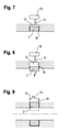
- Figures 7 and 8 Figure 12 shows cross-sectional views of an embodiment which is not part of the invention with an actuating element which is arranged in a socket 10 with socket cavity 12 .
- the actuator may further include an actuator cavity 8 as discussed above.
- the receptacle 10 has a receptacle port 14 for a fluid connection between the receptacle cavity 12 and a pressure generation source 16 .
- the actuating element 2 has a substantially rectangular cross-section, but it can also have a different cross-section, for example one round.
- the actuator of these embodiments, in its non-actuated form 4, may have an elongate shape (ie extend perpendicularly to the plane of the drawing) and be fixed at its ends.
- the actuating member 2 When the receiving cavity 12 is pressurized via the receiving port 14, the actuating member 2 deforms from the non-actuating shape 4 of FIG 7 into the actuation form 6 of 8 .
- the actuating element 2 is fastened at its ends and/or other areas (eg on the inner walls of the receptacle 10) so that the actuating element 2 is not forced out of the receptacle 10.
- the actuating element 2 due to its elasticity, may also move due to a connection with an inside of the receiving 10 returns to its non-actuation form 4.
- FIG. 9 shows a cross-sectional view of an embodiment with an actuating element 2 which is arranged in a receptacle 10 with a receptacle cavity 12 .
- the actuating element 2 can also have an actuating element cavity 8, as explained above.
- the receptacle 10 has a receptacle connection for a fluid connection between the receptacle cavity 12 and a pressure generation source 16 (see, for example, Figures 7 and 8 ) on.
- the actuating element 2 In its non-actuating form 4, the actuating element 2 has an essentially rectangular cross section, but it can also have a different cross section, for example a round one.
- the actuating element 2 of these embodiments is ring-shaped in its non-actuating form 4 (e.g. comparable to an O-ring).
- the receiving cavity 12 is only present in a region of the receiving device 10 , but it can extend like the actuating element 2 in the form of a ring.
- the actuating element 2 When the receiving cavity 12 is pressurized via the first receiving connection, the actuating element 2 deforms from the non-actuating shape 4 shown into an actuating shape 6 indicated by dashed lines. Since the actuating element 2 is ring-shaped, attachment in recording 10 can be dispensed with. When the pressure present in the receiving cavity 12 is released/removed, the actuating element 2 returns to its non-actuating shape 4 due to its elasticity.
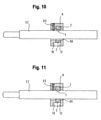
- FIGS 10 and 11 show schematic views of an embodiment for actuating a button T of an e-cigarette.
- This embodiment comprises an essentially ring-shaped holder H with a through-opening DO through which an e-cigarette EZ fits.
- the holder H has a means to secure the e-cigarette EZ in the holder H;
- a threaded pin GS is provided for this purpose, which can be screwed in to secure the e-cigarette EZ and unscrewed to release the same.
- the holder H has a receptacle 10 for an actuating element 2 and a receptacle cavity 12 .
- a receptacle 10 for an actuating element 2 and a receptacle cavity 12 .
- the embodiment of Figures 10 and 11 with the embodiment of 9 comparable.
- FIG. 10 shows the actuating element 2 in its non-actuated form 4, with the receiving cavity 12 not being pressurized or only being pressurized to such an extent that the actuating element 2 is not deformed or is only deformed in such a way that a button T on the e-cigarette is not actuated.
- FIG. 11 shows the actuating element 2 in its actuating form 6, in which case the receiving cavity 12 is pressurized in such a way that the actuating element 2 is deformed in such a way that the button T of the e-cigarette EZ is actuated.
Landscapes
- Engineering & Computer Science (AREA)
- Manufacturing & Machinery (AREA)
- Fluid-Pressure Circuits (AREA)
- Actuator (AREA)
Description
- Die vorliegende Erfindung betrifft das Gebiet mechanischer Taster und Schalter und insbesondere Vorrichtungen und Verfahren für deren Betätigung.
- Mechanische Taster und Schalter sind üblicherweise zur Betätigung durch eine Person, normalerweise mittels eines Fingers oder einer Hand, aber auch per Fuß, vorgesehen. Es kann allerdings erforderlich sein, mechanische Taster und Schalter mittels technischer Mittel zu bedienen, beispielsweise im Rahmen von Funktionsprüfungen des Tasters/Schalter und/oder Tests einer Vorrichtung mit dem Taster/Schalter.
- Ein Beispiel hierfür sind sogenannte E-Zigaretten. Es gibt E-Zigaretten, bei denen mittels eines Tasters (auch Feuerknopf genannt) der Verdampfungsprozess gestartet (Taster vom Raucher/Benutzer gedrückt) und beendet (Taster vom Raucher/Benutzer nicht gedrückt) wird.
- Wie auch bei herkömmlichen Zigaretten, werden auch E-Zigaretten automatisierten Tests unterworfen, um beispielsweise bei Verwendung über das Mundstück abgegebene Stoffe zu ermitteln. Bei den genannten E-Zigaretten mit Taster ist dabei nötig, den Taster mittels eines technischen Mittels betätigen zu können.
- Die
US 6,581,483 offenbart eine Anordnung, bei der mittels eines mit Druck beaufschlagten Zylinders aus diesem heraus ein Stößel bewegt wird, um ein Schaltmittel zu betätigen. - Die
US 2014/0283855 A1 offenbart eine E-Zigarette - Die
österreichische Patentschrift Nr. 2 62429 - Die
FR 2.057.159 - Der vorliegenden Erfindung liegt die Aufgabe zugrunde, eine Lösung zur einfachen und kostengünstigen Betätigen eines Tasters oder Schalters bereitzustellen.
- Diese Aufgabe wird gelöst durch eine Vorrichtung gemäß Anspruch 1.
- Die abhängigen Ansprüche beschreiben bevorzugte Ausführungsformen.
- Im Folgenden werden Ausführungsformen der vorliegenden Erfindung anhand der Zeichnungen beschrieben.
- Fig. 1 und 2
- zeigen Querschnittsansichten einer Ausführungsform mit einem Betätigungselement,
- Fig. 3 und 4
- zeigen Querschnittsansichten einer Ausführungsform mit einem Betätigungselement,
- Fig. 5
- zeigt eine Querschnittsansicht einer Ausführungsform mit zwei Betätigungselementen,
- Fig. 6
- zeigt eine Querschnittsansicht einer Ausführungsform mit zwei Betätigungselementen,
- Fig. 7 und 8
- zeigen Querschnittsansichten einer Ausführungsform, die nicht Teil der Erfindung ist, mit einem Betätigungselement, das in einer Aufnahme mit Aufnahme-Hohlraum angeordnet,
- Fig. 9
- zeigt eine Querschnittsansicht einer Ausführungsform mit einem Betätigungselement, das in einer Aufnahme mit Aufnahme-Hohlraum angeordnet, und
- Fig. 10 und 11
- eine E-Zigaretten-Taster-Betätigungsvorrichtung.
- Im Folgenden wird die Erfindung anhand von in den Figuren dargestellten Ausführungsformen näher erläutert, wobei in den Figuren wenigstens im Wesentlichen funktionsgleiche Elemente die gleichen Bezugszeichen haben. Ferner gelten für verschiedene Ausführungsformen gemachten Ausführungen auch für alle anderen Ausführungsformen, sofern nichts anderes gesagt wird.
- Ferner werden im Folgenden Taster, Schalter und dergleichen zusammenfassend als Schaltmittel bezeichnet.
- Ein Grundgedanke besteht darin, mittels eines elastischen und pneumatisch und/oder hydraulisch verformbaren Betätigungselements ein Schaltmittel zu betätigen.
- Das Betätigungselement kann eine Nicht-Betätigungsform, bei der das Betätigungselement das Schaltmittel nicht betätigt, und eine Betätigungsform haben, bei der das Betätigungselement das Schaltmittel betätigt. In seiner Nicht-Betätigungsform kann das Betätigungselement vom Schaltmittel beabstandet sein oder das Schaltmittel nur so kontaktieren, dass Schaltmittel nicht betätigt wird. In seiner Betätigungsform kontaktiert das Betätigungselement - falls dies nicht schon der Fall vorher war - das Schaltmittel und übt auf das Schaltmittel eine Kraft aus, welche zu einer Betätigung des Schaltmittels verursacht.
- Die Nicht-Betätigungsform des Betätigungselements kann erreicht werden, indem das Bestätigungselement nicht mit pneumatischen und/oder hydraulischen Druck beaufschlagt wird, sodass das Schaltmittel gar nicht kontaktiert, oder mit einem pneumatischen und/oder hydraulischen Druck beaufschlagt wird, dass das Schaltmittel nur derart kontaktiert wird, dass auf das Schaltmittel keine Kraft wirkt, welche zu einer Betätigung des Schaltmittels führt.
- Die Betätigungsform des Betätigungselements kann erreicht werden, indem das Bestätigungselement mit (mehr) pneumatischen und/oder hydraulischen Druck beaufschlagt wird, sodass das Schaltmittel - falls dies nicht schon vorher der Fall ist - kontaktiert wird und auf das Schaltmittel eine Kraft wirkt, welche zu einer Betätigung des Schaltmittels führt.
- In der Nicht-Betätigungsform kann das Betätigungselement vollständig in der Aufnahme angeordnet sein (insbesondere so, dass sich kein Bereich des Betätigungselementes aus der Aufnahme herauserstreckt) oder so, dass es sich teilweise aus der Aufnahme herauserstreckt. In beiden Fällen ist das Betätigungselement entweder vom Schaltmittel beabstandet oder kontaktiert dieses allenfalls so, dass es zu keiner Betätigung des Schaltmittels kommt. Dies gilt auch für Fälle, in denen das Schaltmittel wenigstens teilweise in die Aufnahme hineinragt.
- Das Betätigungselement umfasst wenigstens ein elastisch verformbares Material, wie z.B. Gummi, Silikon oder andere Spezialkunststoffe.
- Ausführungsforinen mit einem Betätigungselement sind beispielsweise für Schaltmittel geeignet, die eine erste Schaltstellung (z.B. ausgeschaltet/eingeschaltet) haben und mittels des Betätigungselementes in eine zweite Schaltstellung (z.B. eingeschaltet/ausgeschaltet) gebracht werden können und die erste Schaltstellung selbsttätig/automatisch einnehmen, wenn das Betätigungselement das Schaltmittel nicht mehr betätigt bzw. wieder die Nicht-Betätigungsform eingenommen hat. Beispielsweise hierfür sind (z.B. mittels Federkraft) in eine erste Stellung vorgespannte Taster oder Kipp-/Wippschalter.
- Ferner sind Ausführungsformen mit zwei Betätigungselementen vorgesehen, insbesondere um Schaltmittel zu betätigen, die ebenfalls erste und zweite Schaltstellungen aufweisen, aber die erste Schaltstellung nicht selbsttätig/automatisch einnehmen, sondern - wie im Fall der zweiten Schaltstellung SSt2 - in diese zu bringen sind. Beispiele hierfür sind Kipp-/Wippschalter, die in keine der Schaltstellungen vorgespannt sind (wie sie beispielsweise als Lichtschalter in Wohnungen zu finden sind).
- Bei derartigen Ausführungsformen ist es vorgesehen, mittels eines ersten Betätigungselementes das Schaltmittel von der ersten Schaltstellung SStl in die zweite Schaltstellung und mittels eines zweiten Betätigungselementes das Schaltmittel von der zweiten Schaltstellung SSt2 in die erste Schaltstellung zu bringen.
- Das Betätigungselement ist in Form eines Rings ausgebildet, der jeweils einen Betätigungselement-Hohlraum aufweist, in dem pneumatisch und/oder hydraulisch Druck aufgebaut und wieder entfernt werden kann, um das Betätigungselement gesteuert zu verformen, und zwar ausgehend von der Nicht-Betätigungsform in die Betätigungsform und wieder zurück, sowie um Nicht-Betätigungsform und die Betätigungsform beizubehalten.
- Erfindungsgemäß ist ein Aufnahme-Hohlraum vorgesehen, der zwischen einer Innenseite einer Aufnahme für ein Betätigungselement und einer Außenseite des Betätigungselementes angeordnet ist. In dem Aufnahme-Hohlraum kann pneumatisch und/oder hydraulisch Druck aufgebaut und wieder entfernt werden, um das Betätigungselement gesteuert zu verformen, und zwar ausgehend von der Nicht-Betätigungsform in die Betätigungsform und wieder zurück, sowie um Nicht-Betätigungsform und die Betätigungsform beizubehalten.
- Betätigungselemente mit einem Betätigungselement-Hohlraum können einen ersten Betätigungselement-Anschluss aufweisen, über den pneumatischer und/oder hydraulischer Druck von einer Druckerzeugungsquelle beispielsweise über eine Leitung oder Schlauch in den Betätigungselement-Hohlraum zugeführt werden kann. Der erste Betätigungselement-Anschluss kann auch dazu dienen, im Betätigungselement-Hohlraum eines Betätigungselementes vorhandenen pneumatischen und/oder hydraulischen Druck zu entfernen/verringern. Alternativ kann hierfür ein zweiter Betätigungselement-Anschluss vorgesehen sein, der beispielsweise steuerbar den Betätigungselement-Hohlraum mit der Umgebungsatmosphäre/-luft verbinden kann.
- Im Fall eines Aufnahme-Hohlraums kann dieser einen ersten Aufnahme-Anschluss aufweisen, über den pneumatischer und/oder hydraulischer Druck von einer Druckerzeugungsquelle beispielsweise über eine Leitung oder Schlauch in den Betätigungselement-Hohlraum zugeführt werden kann. Der erste Aufnahme-Anschluss kann auch dazu dienen, im Betätigungselement-Hohlraum eines Betätigungselementes vorhandenen dramatischen und/oder hydraulischen Druck zu entfernen/verringern. Alternativ kann hierfür ein zweiter Aufnahme-Anschluss vorgesehen sein, der beispielsweise steuerbar den Betätigungselement-Hohlraum mit der Umgebungsatmosphäre/-luft verbinden kann.
- Die Druckerzeugungsquelle kann mittels einer Steuereinrichtung zur Erzeugung pneumatischen und/oder hydraulischen Druckes und dessen Abgabe an ein Betätigungselement gesteuert werden. Ergänzend oder alternativ kann der erste Anschluss gesteuert sein, um selektiv eine Fluidverbindung zwischen der Druckerzeugungsquelle und dem Betätigungselement-Hohlraum des Betätigungselements herzustellen bzw. zu unterbrechen. Im Fall eines zweiten Anschluss kann dieser gesteuert sein, um selektiv eine Fluidverbindung zwischen dem Betätigungselement-Hohlraum des Betätigungselements und der Umgebung herzustellen bzw. zu unterbrechen.
-
Fig. 1 und 2 zeigen Querschnittsansichten einer Ausführungsform mit einem Betätigungselement zur Betätigung eines Schaltmittels SM, hier erfindungsgemäß ein eine erste Schaltstellung SStl vorgespannten Taster T. -
Fig. 1 zeigt das Betätigungselement 2 in seiner Nicht-Betätigungsform 4 undFig. 2 zeigt das Betätigungselement 2 in seiner Betätigungsform. - Das Betätigungselement 2 weist einen Betätigungselement-Hohlraum 8 auf.
- Das Betätigungselement 2 hat in seiner Nicht-Betätigungsform 4 hat einen im Wesentlichen rechteckigen Querschnitt. Das Betätigungselement 2 ist in seiner Nicht-Betätigungsform 4 ringförmig (d.h. radial um einen Punkt in der Zeichnungsebene erstrecken).
- Das Betätigungselement 2 ist einer Aufnahme angeordnet und weist einen hier nicht gezeigten ersten Betätigungselement-Anschluss, der eine Fluidverbindung zwischen dem Betätigungselement-Hohlraum und einer Druckerzeugungsquelle auf.
- Der Taster T ist beispielsweise mittels einer Feder F in eine erste in
Fig. 1 gezeigte Schaltstellung SStl vorgespannt und kann mittels einer in der Zeichnungsebene nach unten wirkenden Kraft in eine zweite, inFig. 2 gezeigte Schaltstellung SSt2 bewegt werden. Letzteres stellt eine Betätigung des Tasters T dar. - Wenn der Betätigungselement-Hohlraum 8 über den ersten Betätigungselement-Anschluss mit Druck beaufschlagt wird, verformt sich das Betätigungselement 2 aus der Nicht-Betätigungsform 4 von
Fig. 1 in die Betätigungsform vonFig. 2 und kontaktiert den Taster T und wirkt mit einer Kraft in Richtung des Pfeiles P auf den Taster T, wodurch dieser betätigt wird, d.h. entgegen der Vorspannkraft in die erste Schaltstellung SStl bewegt wird. - Wenn der im Betätigungselement-Hohlraum 8 vorhandene Druck über den ersten Betätigungselement-Anschluss (oder alternativ einen zweiten Betätigungselement-Anschluss wie oben ausgeführt) vollständig oder wenigstens soweit abgelassen/entfernt wird, dass das Betätigungselement 2 in seine Nicht-Betätigungsform 4 zurückgeht bzw. die auf den Taster T wirkende Kraft des Betätigungselementes 2 kleiner als die auf den Taster T wirkende Kraft der Feder ist, bewegt sich der Taster T in die erste Schaltstellung SStl zurück.
-
Fig. 3 und 4 zeigen Querschnittsansichten einer Ausführungsform mit einem Betätigungselement 2 zur Betätigung eines Schaltmittels SM, hier beispielhaft ein eine erste Schaltstellung SStl vorgespannten Kipp-/Wippschalter KWS. -
Fig. 3 zeigt das Betätigungselement 2 in seiner Nicht-Betätigungsform 4 undFig. 4 zeigt das Betätigungselement 2 in seiner Betätigungsform. - Das Betätigungselement 2 weist einen Betätigungselement-Hohlraum 8 auf.
- Das Betätigungselement 2 hat in seiner Nicht-Betätigungsform 4 hat einen im Wesentlichen runden Querschnitt. Das Betätigungselement 2 ist ringförmig (d.h. radial um einen Punkt in der Zeichnungsebene erstrecken).
- Das Betätigungselement 2 ist einer Aufnahme 10 angeordnet und weist einen hier nicht gezeigten ersten Betätigungselement-Anschluss für eine Fluidverbindung zwischen dem Betätigungselement-Hohlraum 8 und einer Druckerzeugungsquelle auf.
- Der Kipp-/Wippschalter KWS ist beispielsweise mittels einer Feder F in eine erste in
Fig. 3 gezeigte Schaltstellung SStl vorgespannt und kann mittels einer in der Zeichnungsebene nach unten wirkenden Kraft in eine zweite, inFig. 4 gezeigte Schaltstellung SSt2 bewegt werden. Letzteres stellt eine Betätigung des Kipp-/Wippschalter KWS dar. - Wenn der Betätigungselement-Hohlraum 8 über den ersten Betätigungselement-Anschluss mit Druck beaufschlagt wird, verformt sich das Betätigungselement 2 aus der Nicht-Betätigungsform 4 von
Fig. 3 in die Betätigungsform vonFig. 4 und kontaktiert den Kipp-/Wippschalter KWS und wirkt mit einer Kraft in Richtung des Pfeiles Pauf den Kipp-/Wippschalter KWS, wodurch dieser betätigt wird, d.h. entgegen der Vorspannkraft in die erste Schaltstellung SSt2 bewegt wird. - Wenn der im Betätigungselement-Hohlraum 8 vorhandene Druck über den ersten Betätigungselement-Anschluss (oder alternativ einen zweiten Betätigungselement-Anschluss wie oben ausgeführt) vollständig oder wenigstens soweit abgelassen/entfernt wird, dass das Betätigungselement 2 in seine Nicht-Betätigungsform 4 zurückgeht bzw. die auf den Kipp-/Wippschalter KWS wirkende Kraft des Betätigungselementes 2 kleiner als die auf den Kipp-/Wippschalter KWS wirkende Kraft der Feder ist, bewegt sich der Kipp-/Wippschalter KWS in die erste Schaltstellung SStl zurück.
-
Fig. 5 zeigt eine Querschnittsansicht einer Ausführungsform mit zwei Betätigungselementen 2a und 2b zur Betätigung eines Schaltmittels SM, hier beispielhaft ein in keine Stellung vorgespannten Wippschalter WS. -
Fig. 5 zeigt die Betätigungselemente 2a und 2b in ihren Nicht-Betätigungsformen 4. - Die Betätigungselemente 2a und 2b sind hinsichtlich ihrer Querschnittsformen vergleichbar mit dem Betätigungselemente von
Fig. 1 , können jeweils aber auch eine andere Querschnittsform haben, beispielsweise die vonFig. 3 . - Das Betätigungselement 2a weist einen Betätigungselement-Hohlraum 8a auf und das Betätigungselement 2b weist einen Betätigungselement-Hohlraum 8b auf.
- Die Betätigungselemente 2a und 2b sind jeweils in einer Aufnahme 10a und 10b angeordnet und weisen jeweils einen hier nicht gezeigten ersten Betätigungselement-Anschluss für eine Fluidverbindung zwischen dem jeweiligen Betätigungselement-Hohlraum 8a bzw. 8b und einer Druckerzeugungsquelle auf.
- Der Wippschalter WS kann eine in
Fig. 5 mit durchgezogener Linie gezeigte erste Schaltstellung SStl und eine inFig. 5 mit gestrichelter Linie gezeigte zweite Schaltstellung SSt2 einnehmen, und zwar durch Schwenken um eine Achse A, wie dies durch den Pfeil PA angedeutet ist. - Wenn der Betätigungselement-Hohlraum 8a des Betätigungselements 2a mit Druck beaufschlagt wird, verformt sich das Betätigungselement 2a aus seiner Nicht-Betätigungsform 4 in seine Betätigungsform 6, wie sie beispielsweise in
Fig. 2 gezeigt ist, kontaktiert den Wippschalter WS und wirkt mit einer Kraft in Richtung des Pfeiles P1 auf den Wippschalter WS, wodurch dieser betätigt wird, d.h. in die zweite Schaltstellung SSt2 bewegt wird. - Je nach Bauform des Wippschalters WS kann es hilfreich sein, den Druck im Betätigungselement-Hohlraum 8a des Betätigungselements 2a aufrechtzuhalten, um den Wippschalter WS in der zweiten Schaltstellung SSt2 zu halten. Entsprechendes gilt für den Betätigungselement-Hohlraum 8b des Betätigungselements 2b.
- Um den Wippschalter WS von der zweiten Schaltstellung SSt2 in die erste Schaltstellung SStl zurück zu bringen, wird Betätigungselement-Hohlraum 8b des Betätigungselements 2b mit Druck beaufschlagt wird, wodurch sich das Betätigungselement 2b aus seiner Nicht-Betätigungsform 4 in seine Betätigungsform 6, wie sie beispielsweise in
Fig. 2 gezeigt ist, verformt, den Wippschalter WS kontaktiert und mit einer Kraft in Richtung des Pfeiles P2 auf den Wippschalter WS wirkt, wodurch dieser betätigt wird, d.h. in die erste Schaltstellung SStl bewegt wird. Hierbei kann es gegebenenfalls erforderlich sein, den Druck im Betätigungselement-Hohlraum 8a des Betätigungselements 2a vor oder zeitgleich mit dem Druckaufbau im Betätigungselement 8b des Betätigungselements 2b zu reduzieren bzw. zu entfernen. -
Fig. 6 zeigt eine Querschnittsansicht einer Ausführungsform mit zwei Betätigungselementen 2a und 2b zur Betätigung eines Schaltmittels SM, hier beispielhaft ein in keine Stellung vorgespannten Kippschalter KS. -
Fig. 6 zeigt die Betätigungselemente 2a und 2b in ihren Nicht-Betätigungsformen. - Die Betätigungselemente 2a und 2b sind hinsichtlich ihrer Querschnittsformen vergleichbar mit dem Betätigungselemente von
Fig. 1 , können jeweils aber auch eine andere Querschnittsform haben, beispielsweise die vonFig. 3 . - Die Betätigungselemente 2a und 2b sind jeweils in einer Aufnahme 10a bzw. 10b angeordnet und weisen jeweils einen hier nicht gezeigten ersten Betätigungselement-Anschluss für eine Fluidverbindung zwischen dem jeweiligen Betätigungselement-Hohlraum 8a bzw. 8b und einer Druckerzeugungsquelle auf.
- Der Kippschalter KS kann eine in
Fig. 5 mit durchgezogener Linie gezeigte erste Schaltstellung SStl und eine inFig. 5 mit gestrichelter Linie gezeigte erste Schaltstellung SSt2 einnehmen, und zwar durch Schwenken um eine Achse A, wie dies durch den Pfeil PA angedeutet ist. - Wenn der Betätigungselement-Hohlraum 8a des Betätigungselements 2a mit Druck beaufschlagt wird, verformt sich das Betätigungselement 2a aus seiner Nicht-Betätigungsform 4 in seine Betätigungsform 6, wie sie beispielsweise in
Fig. 2 gezeigt ist, kontaktiert den Kippschalter KS und wirkt mit einer Kraft in Richtung des Pfeiles P1 auf den Kippschalter KS, wodurch dieser betätigt wird, d.h. in die erste Schaltstellung SSt2 bewegt wird. - Je nach Bauform des Kippschalters KS kann es hilfreich sein, den Druck im Betätigungselement-Hohlraum 8a des Betätigungselements 2a aufrechtzuhalten, um den Kippschalter KS in der zweiten Schaltstellung SSt2 zu halten.
- Um den Kippschalter KS von der zweiten Schaltstellung SSt2 in die erste Schaltstellung SStl zurück zu bringen, wird Betätigungselement-Hohlraum 8b des Betätigungselements 2b mit Druck beaufschlagt wird, wodurch sich das Betätigungselement 2a aus seiner Nicht-Betätigungsform 4 in seine Betätigungsform 6, wie sie beispielsweise in
Fig. 2 gezeigt ist, verformt, den Kippschalter KS kontaktiert und mit einer Kraft in Richtung des Pfeiles auf den Kippschalter KS wirkt, wodurch dieser betätigt wird, d.h. in die erste Schaltstellung SStl bewegt wird. Hierbei kann es gegebenenfalls erforderlich sein, den Druck im Betätigungselement-Hohlraum 8a des Betätigungselements 2a vor oder zeitgleich mit dem Druckaufbau im Betätigungselement-Hohlraum 8b des Betätigungselements 2b zu reduzieren bzw. zu entfernen. -
Fig. 7 und 8 zeigen Querschnittsansichten einer Ausführungsform, die nicht Teil der Erfindung ist, mit einem Betätigungselement, das in einer Aufnahme 10 mit Aufnahme-Hohlraum 12 angeordnet ist. Alternativ kann das Betätigungselement ferner, wie oben ausgeführt einen Betätigungselement-Hohlraum 8 aufweisen. - Die Aufnahme 10 weist einen Aufnahme-Anschluss 14 für eine Fluidverbindung zwischen dem Aufnahme-Hohlraum 12 und einer Druckerzeugungsquelle 16 auf.
- Das Betätigungselement 2 hat in seiner Nicht-Betätigungsform 4 hat einen im Wesentlichen rechteckigen Querschnitt, kann aber auch einen anderen Querschnitt haben, beispielsweise einen runden. Das Betätigungselement dieser Ausführungsformen kann in seiner Nicht-Betätigungsform 4 eine längliche Form haben (d.h. sich senkrecht zur Zeichnungsebene erstrecken) und an seinen Enden befestigt sein.
- Wenn der Aufnahme-Hohlraum 12 über den Aufnahme-Anschluss 14 mit Druck beaufschlagt wird, verformt sich das Betätigungselement 2 aus der Nicht-Betätigungsform 4 von
Fig. 7 in die Betätigungsform 6 vonFig. 8 . Bei den hier vorgesehenen Ausführungsformen kann es hilfreich sein, wenn das Betätigungselement 2 an seinen Enden und/oder anderen Bereichen (z.B. an Innenwänden der Aufnahme 10) befestigt ist, damit Betätigungselement 2 nicht aus der Aufnahme 10 gedrängt wird. - Wenn der im Aufnahme-Hohlraum 12 vorhandene Druck über den Aufnahme-Anschluss 14 (oder alternativ einen zweiten Aufnahme-Anschluss wie oben ausgeführt) abgelassen/entfernt wird, geht das Betätigungselement 2 aufgrund seiner Elastizität gegebenenfalls auch aufgrund einer Verbindung mit einer Innenseite der Aufnahme 10 seine Nicht-Betätigungsform 4 zurück.
-
Fig. 9 zeigt eine Querschnittsansicht einer Ausführungsform mit einem Betätigungselement 2, das in einer Aufnahme 10 mit Aufnahme-Hohlraum 12 angeordnet ist. Alternativ kann das Betätigungselement 2 ferner, wie oben ausgeführt einen Betätigungselement-Hohlraum 8 aufweisen. - Die Aufnahme 10 weist einen Aufnahme-Anschluss für eine Fluidverbindung zwischen dem Aufnahme-Hohlraum 12 und einer Druckerzeugungsquelle 16 (s. z.B.
Fig. 7 und 8 ) auf. - Das Betätigungselement 2 hat in seiner Nicht-Betätigungsform 4 hat einen im Wesentlichen rechteckigen Querschnitt, kann aber auch einen anderen Querschnitt haben, beispielsweise einen runden. Das Betätigungselement 2 dieser Ausführungsformen ist in seiner Nicht-Betätigungsform 4 ringförmig (z.B. vergleichbar mit einem O-Ring).
- Der Aufnahme-Hohlraum 12 ist gemäß der Darstellung nur in einem Bereich der Aufnahme 10 vorhanden, kann sich aber wie das Betätigungselement 2 ringförmig erstrecken.
- Wenn der Aufnahme-Hohlraum 12 über den ersten Aufnahme-Anschluss mit Druck beaufschlagt wird, verformt sich das Betätigungselement 2 aus der gezeigten Nicht-Betätigungsform 4 in eine durch gestrichelte Linien angedeutete Betätigungsform 6. Da das Betätigungselement 2 ringförmig ist, kann auf eine Befestigung in der Aufnahme 10 verzichtet werden. Wenn der im Aufnahme-Hohlraum 12 vorhandene Druck abgelassen/entfernt wird, geht das Betätigungselement 2 aufgrund seiner Elastizität seine Nicht-Betätigungsform 4 zurück.
-
Fig. 10 und 11 zeigen schematische Ansichten einer Ausführungsform zur Betätigung eines Tasters T einer E-Zigarette. Diese Ausführungsform umfasst einen im Wesentlichen ringförmigen Halter H mit einer Durchgangsöffnung DO, durch die eine E-Zigarette EZ passt. Der Halter H weist ein Mittel auf, um die E-Zigarette EZ in dem Halter H zu sichern; darstellungsgemäß ist hierfür ein Gewindestift GS vorgesehen, der zum Sichern der E-Zigarette EZ eingeschraubt und zum Lösen derselben herausgeschraubt werden kann. - Der Halter H weist eine Aufnahme 10 für ein Betätigungselement 2 und einen Aufnahme-Hohlraum 12 auf. In dieser Hinsicht ist die Ausführungsform von
Fig. 10 und 11 mit der Ausführungsform vonFig. 9 vergleichbar. -
Fig. 10 zeigt das Betätigungselement 2 in seiner Nicht-Betätigungsform 4, wobei hier der Aufnahme-Hohlraum 12 nicht oder nur so mit Druck beaufschlagt ist, dass das Betätigungselement 2 nicht oder nur so verformt wird, dass ein Taster T der E-Zigarette nicht betätigt wird. -
Fig. 11 zeigt das Betätigungselement 2 in seiner Betätigungsform 6, wobei hier der Aufnahme-Hohlraum 12 so mit Druck beaufschlagt ist, dass das Betätigungselement 2 so verformt wird, dass der Taster T der E-Zigarette EZ betätigt wird.
Claims (5)
- Betätigungsvorrichtung für einen Taster (T), umfassend- ein elastisches Betätigungselement (2; 2a, 2b) mit einer Nicht-Betätigungsform (4) ohne Betätigung des Tasters (T) und einer Betätigungsform (6) zur Betätigung des Tasters (T),
dadurch gekennzeichnet, dass- das Betätigungselement (2; 2a, 2b) ringförmig ist und in einer ringförmigen in einem Halter (H) ausgebildeten Aufnahme (10) angeordnet ist,- ein dem Betätigungselement (2; 2a, 2b) zugeordneter Aufnahme-Hohlraum (8; 8a, 8b; 12) vorgesehen ist, der zwischen einer Innenseite der Aufnahme (10) und einer Außenseite des Betätigungselementes (2; 2a, 2b) angeordnet ist und der mittels pneumatischen und/oder hydraulischen Drucks beaufschlagbar ist, um das Betätigungselement (2; 2a, 2b) aus der Nicht-Betätigungsform (4) in die Betätigungsform (6) zu bringen,- das Betätigungselement (2; 2a, 2b) aufgrund seiner Elastizität in seine Nicht-Betätigungsform (4) zurückgeht, wenn der Druck im Aufnahme-Hohlraum (12) abgelassen/entfernt wird. - Betätigungsvorrichtung nach dem vorherigen Patentanspruch, bei der der Halter (H) ringförmig ausgebildet ist und eine Durchgangsöffnung (DO) mit kreisförmigem Querschnitt zur Aufnahme einer E-Zigarette (EZ) aufweist, wobei die Aufnahme (10) konzentrisch zu der Durchgangsöffnung (DO) und so angeordnet ist, dass sich das Betätigungselement (2; 2a, 2b) in seiner Betätigungsform in die Durchgangsöffnung (DO) erstreckt.
- Betätigungsvorrichtung nach einem der vorherigen Patentansprüche, bei der das Betätigungselement (2; 2a, 2b) ein 0-Ring ist.
- Betätigungsvorrichtung nach einem der vorherigen Patentansprüche, bei der der Aufnahme-Hohlraum (12) einen Aufnahme-Anschluss zum Anschluss an eine Druckerzeugungsquelle aufweist.
- Betätigungsvorrichtung nach dem vorherigen Patentanspruch, ferner mit einer Steuereinrichtung zur Steuerung der Druckerzeugungsquelle.
Applications Claiming Priority (2)
| Application Number | Priority Date | Filing Date | Title |
|---|---|---|---|
| DE102016003048.8A DE102016003048A1 (de) | 2016-03-11 | 2016-03-11 | Vorrichtung und verfahren zur betätigung mechanischer schaltmittel |
| PCT/EP2017/000327 WO2017153051A1 (de) | 2016-03-11 | 2017-03-12 | Vorrichtung und verfahren zur betätigung mechanischer schaltmittel |
Publications (2)
| Publication Number | Publication Date |
|---|---|
| EP3427282A1 EP3427282A1 (de) | 2019-01-16 |
| EP3427282B1 true EP3427282B1 (de) | 2022-03-02 |
Family
ID=58397975
Family Applications (1)
| Application Number | Title | Priority Date | Filing Date |
|---|---|---|---|
| EP17717622.9A Active EP3427282B1 (de) | 2016-03-11 | 2017-03-12 | Vorrichtung und verfahren zur betätigung mechanischer schaltmittel |
Country Status (4)
| Country | Link |
|---|---|
| US (1) | US20210134539A1 (de) |
| EP (1) | EP3427282B1 (de) |
| DE (1) | DE102016003048A1 (de) |
| WO (1) | WO2017153051A1 (de) |
Families Citing this family (18)
| Publication number | Priority date | Publication date | Assignee | Title |
|---|---|---|---|---|
| US20160345631A1 (en) | 2005-07-19 | 2016-12-01 | James Monsees | Portable devices for generating an inhalable vapor |
| US10279934B2 (en) | 2013-03-15 | 2019-05-07 | Juul Labs, Inc. | Fillable vaporizer cartridge and method of filling |
| EP3928646B1 (de) | 2013-12-23 | 2025-03-26 | Juul Labs International Inc. | Verdampfungsvorrichtungssysteme |
| USD825102S1 (en) | 2016-07-28 | 2018-08-07 | Juul Labs, Inc. | Vaporizer device with cartridge |
| US10058129B2 (en) | 2013-12-23 | 2018-08-28 | Juul Labs, Inc. | Vaporization device systems and methods |
| US20160366947A1 (en) | 2013-12-23 | 2016-12-22 | James Monsees | Vaporizer apparatus |
| USD842536S1 (en) | 2016-07-28 | 2019-03-05 | Juul Labs, Inc. | Vaporizer cartridge |
| US10076139B2 (en) | 2013-12-23 | 2018-09-18 | Juul Labs, Inc. | Vaporizer apparatus |
| US10159282B2 (en) | 2013-12-23 | 2018-12-25 | Juul Labs, Inc. | Cartridge for use with a vaporizer device |
| RU2709926C2 (ru) | 2014-12-05 | 2019-12-23 | Джуул Лэбз, Инк. | Контроль калиброванной дозы |
| EP3419443A4 (de) | 2016-02-11 | 2019-11-20 | Juul Labs, Inc. | Sicheres befestigen von kartuschen für verdampfervorrichtungen |
| SG11201806793TA (en) | 2016-02-11 | 2018-09-27 | Juul Labs Inc | Fillable vaporizer cartridge and method of filling |
| US10405582B2 (en) | 2016-03-10 | 2019-09-10 | Pax Labs, Inc. | Vaporization device with lip sensing |
| USD849996S1 (en) | 2016-06-16 | 2019-05-28 | Pax Labs, Inc. | Vaporizer cartridge |
| USD836541S1 (en) | 2016-06-23 | 2018-12-25 | Pax Labs, Inc. | Charging device |
| USD851830S1 (en) | 2016-06-23 | 2019-06-18 | Pax Labs, Inc. | Combined vaporizer tamp and pick tool |
| USD887632S1 (en) | 2017-09-14 | 2020-06-16 | Pax Labs, Inc. | Vaporizer cartridge |
| US20250134166A1 (en) * | 2021-11-04 | 2025-05-01 | Philip Morris Products S.A. | Aerosol-generating device with button centering |
Family Cites Families (7)
| Publication number | Priority date | Publication date | Assignee | Title |
|---|---|---|---|---|
| AT262429B (de) * | 1964-04-27 | 1968-06-10 | Uninorm Anstalt | Fernbetätigbare Schaltvorrichtung |
| FR2057159A5 (de) * | 1969-08-04 | 1971-05-21 | Arnould Ets | |
| US3900710A (en) * | 1973-10-01 | 1975-08-19 | John Potter | Squeezably actuated general purpose electric switch |
| US4309993A (en) * | 1980-03-06 | 1982-01-12 | Baxter Travenol Laboratories, Inc. | Liquid flow sensing apparatus |
| US4501583A (en) * | 1983-06-15 | 1985-02-26 | Extracorporeal, Inc. | Hemodialysis access monitors |
| TW387559U (en) * | 1999-08-06 | 2000-04-11 | Darfon Electronics Corp | Air-buffered tester for key service life |
| MX2015013513A (es) * | 2013-03-22 | 2016-10-26 | Altria Client Services Llc | Articulo electronico para fumar. |
-
2016
- 2016-03-11 DE DE102016003048.8A patent/DE102016003048A1/de active Pending
-
2017
- 2017-03-12 US US16/084,163 patent/US20210134539A1/en not_active Abandoned
- 2017-03-12 WO PCT/EP2017/000327 patent/WO2017153051A1/de not_active Ceased
- 2017-03-12 EP EP17717622.9A patent/EP3427282B1/de active Active
Also Published As
| Publication number | Publication date |
|---|---|
| EP3427282A1 (de) | 2019-01-16 |
| US20210134539A1 (en) | 2021-05-06 |
| DE102016003048A1 (de) | 2017-09-14 |
| WO2017153051A1 (de) | 2017-09-14 |
Similar Documents
| Publication | Publication Date | Title |
|---|---|---|
| EP3427282B1 (de) | Vorrichtung und verfahren zur betätigung mechanischer schaltmittel | |
| DE2437657A1 (de) | Druckabhaengige schalteinrichtung zur verwendung an einem luftreifen | |
| DE3738075A1 (de) | Stromkreissteuervorrichtung und verfahren zum betaetigen derselben | |
| EP3234974B1 (de) | Bedienvorrichtung für ein fahrzeug, insbesondere einen personenkraftwagen | |
| DE10347936B4 (de) | Ventilanordnung mit einstellbarer Funktion und Verfahren hierfür | |
| DE102017115191A1 (de) | Ventil, insbesondere Servoventil | |
| DE60128356T2 (de) | Mechanische rücksetzvorrichtung für schalter | |
| EP2894265B1 (de) | Pneumatische Betätigungsvorrichtung | |
| DE102017201049A1 (de) | Kugelgelenk für ein Fahrzeug | |
| DE60030934T2 (de) | Anordnung zur verstärkung des hubs eines betätigungsorgans eines schalters | |
| DE1109762B (de) | Schalter | |
| DE102013003575B4 (de) | Druck- und drehbetätigbares Bedienelement für ein Kraftfahrzeug | |
| DE3432028A1 (de) | Beschaltungswerkzeug fuer den schwachstrom-anlagenbau | |
| DE202015106505U1 (de) | Greifer | |
| DE112018001484T5 (de) | Anordnung eines steuergeräts und mindestens eines mikroschalters | |
| DE458460C (de) | Abreisshebel, insbesondere des Unterbrechers von Magnetos | |
| DE4227353A1 (de) | Steuergriffanordnung, insbesondere zur Verwendung mit einer druckmittelbetriebenen Steuergeberanordnung | |
| DE2062977C3 (de) | Abstreifvorrichtung | |
| DE102014222284A1 (de) | Bedieneinrichtung | |
| DE202005001495U1 (de) | 2-poliger Umschalter | |
| DE19603921C1 (de) | Druckschalter | |
| DE102017104870B3 (de) | Brause mit einer zwei Antriebselemente aufweisenden Umschaltvorrichtung | |
| DE102011119943A1 (de) | Betätigungselement | |
| DE974388C (de) | Lenkhandrad fuer Kraftfahrzeuge | |
| DE102007059194A1 (de) | Vorrichtung zum Verbinden von zwei Endteilen eines Schmuckelements, insbesondere eines Halsreifs, und Verfahren zum Herstellen einer solchen Vorrichtung |
Legal Events
| Date | Code | Title | Description |
|---|---|---|---|
| STAA | Information on the status of an ep patent application or granted ep patent |
Free format text: STATUS: UNKNOWN |
|
| STAA | Information on the status of an ep patent application or granted ep patent |
Free format text: STATUS: THE INTERNATIONAL PUBLICATION HAS BEEN MADE |
|
| PUAI | Public reference made under article 153(3) epc to a published international application that has entered the european phase |
Free format text: ORIGINAL CODE: 0009012 |
|
| STAA | Information on the status of an ep patent application or granted ep patent |
Free format text: STATUS: REQUEST FOR EXAMINATION WAS MADE |
|
| 17P | Request for examination filed |
Effective date: 20181011 |
|
| AK | Designated contracting states |
Kind code of ref document: A1 Designated state(s): AL AT BE BG CH CY CZ DE DK EE ES FI FR GB GR HR HU IE IS IT LI LT LU LV MC MK MT NL NO PL PT RO RS SE SI SK SM TR |
|
| AX | Request for extension of the european patent |
Extension state: BA ME |
|
| DAV | Request for validation of the european patent (deleted) | ||
| DAX | Request for extension of the european patent (deleted) | ||
| GRAP | Despatch of communication of intention to grant a patent |
Free format text: ORIGINAL CODE: EPIDOSNIGR1 |
|
| STAA | Information on the status of an ep patent application or granted ep patent |
Free format text: STATUS: GRANT OF PATENT IS INTENDED |
|
| INTG | Intention to grant announced |
Effective date: 20210713 |
|
| GRAJ | Information related to disapproval of communication of intention to grant by the applicant or resumption of examination proceedings by the epo deleted |
Free format text: ORIGINAL CODE: EPIDOSDIGR1 |
|
| STAA | Information on the status of an ep patent application or granted ep patent |
Free format text: STATUS: REQUEST FOR EXAMINATION WAS MADE |
|
| GRAJ | Information related to disapproval of communication of intention to grant by the applicant or resumption of examination proceedings by the epo deleted |
Free format text: ORIGINAL CODE: EPIDOSDIGR1 |
|
| GRAS | Grant fee paid |
Free format text: ORIGINAL CODE: EPIDOSNIGR3 |
|
| STAA | Information on the status of an ep patent application or granted ep patent |
Free format text: STATUS: GRANT OF PATENT IS INTENDED |
|
| INTC | Intention to grant announced (deleted) | ||
| GRAP | Despatch of communication of intention to grant a patent |
Free format text: ORIGINAL CODE: EPIDOSNIGR1 |
|
| INTG | Intention to grant announced |
Effective date: 20220107 |
|
| GRAA | (expected) grant |
Free format text: ORIGINAL CODE: 0009210 |
|
| STAA | Information on the status of an ep patent application or granted ep patent |
Free format text: STATUS: THE PATENT HAS BEEN GRANTED |
|
| AK | Designated contracting states |
Kind code of ref document: B1 Designated state(s): AL AT BE BG CH CY CZ DE DK EE ES FI FR GB GR HR HU IE IS IT LI LT LU LV MC MK MT NL NO PL PT RO RS SE SI SK SM TR |
|
| REG | Reference to a national code |
Ref country code: GB Ref legal event code: FG4D Free format text: NOT ENGLISH |
|
| REG | Reference to a national code |
Ref country code: CH Ref legal event code: EP Ref country code: AT Ref legal event code: REF Ref document number: 1472925 Country of ref document: AT Kind code of ref document: T Effective date: 20220315 |
|
| REG | Reference to a national code |
Ref country code: DE Ref legal event code: R096 Ref document number: 502017012689 Country of ref document: DE |
|
| REG | Reference to a national code |
Ref country code: IE Ref legal event code: FG4D Free format text: LANGUAGE OF EP DOCUMENT: GERMAN |
|
| REG | Reference to a national code |
Ref country code: LT Ref legal event code: MG9D |
|
| REG | Reference to a national code |
Ref country code: NL Ref legal event code: MP Effective date: 20220302 |
|
| PG25 | Lapsed in a contracting state [announced via postgrant information from national office to epo] |
Ref country code: SE Free format text: LAPSE BECAUSE OF FAILURE TO SUBMIT A TRANSLATION OF THE DESCRIPTION OR TO PAY THE FEE WITHIN THE PRESCRIBED TIME-LIMIT Effective date: 20220302 Ref country code: RS Free format text: LAPSE BECAUSE OF FAILURE TO SUBMIT A TRANSLATION OF THE DESCRIPTION OR TO PAY THE FEE WITHIN THE PRESCRIBED TIME-LIMIT Effective date: 20220302 Ref country code: NO Free format text: LAPSE BECAUSE OF FAILURE TO SUBMIT A TRANSLATION OF THE DESCRIPTION OR TO PAY THE FEE WITHIN THE PRESCRIBED TIME-LIMIT Effective date: 20220602 Ref country code: LT Free format text: LAPSE BECAUSE OF FAILURE TO SUBMIT A TRANSLATION OF THE DESCRIPTION OR TO PAY THE FEE WITHIN THE PRESCRIBED TIME-LIMIT Effective date: 20220302 Ref country code: HR Free format text: LAPSE BECAUSE OF FAILURE TO SUBMIT A TRANSLATION OF THE DESCRIPTION OR TO PAY THE FEE WITHIN THE PRESCRIBED TIME-LIMIT Effective date: 20220302 Ref country code: ES Free format text: LAPSE BECAUSE OF FAILURE TO SUBMIT A TRANSLATION OF THE DESCRIPTION OR TO PAY THE FEE WITHIN THE PRESCRIBED TIME-LIMIT Effective date: 20220302 Ref country code: BG Free format text: LAPSE BECAUSE OF FAILURE TO SUBMIT A TRANSLATION OF THE DESCRIPTION OR TO PAY THE FEE WITHIN THE PRESCRIBED TIME-LIMIT Effective date: 20220602 |
|
| PG25 | Lapsed in a contracting state [announced via postgrant information from national office to epo] |
Ref country code: PL Free format text: LAPSE BECAUSE OF FAILURE TO SUBMIT A TRANSLATION OF THE DESCRIPTION OR TO PAY THE FEE WITHIN THE PRESCRIBED TIME-LIMIT Effective date: 20220302 Ref country code: LV Free format text: LAPSE BECAUSE OF FAILURE TO SUBMIT A TRANSLATION OF THE DESCRIPTION OR TO PAY THE FEE WITHIN THE PRESCRIBED TIME-LIMIT Effective date: 20220302 Ref country code: GR Free format text: LAPSE BECAUSE OF FAILURE TO SUBMIT A TRANSLATION OF THE DESCRIPTION OR TO PAY THE FEE WITHIN THE PRESCRIBED TIME-LIMIT Effective date: 20220603 Ref country code: FI Free format text: LAPSE BECAUSE OF FAILURE TO SUBMIT A TRANSLATION OF THE DESCRIPTION OR TO PAY THE FEE WITHIN THE PRESCRIBED TIME-LIMIT Effective date: 20220302 |
|
| PG25 | Lapsed in a contracting state [announced via postgrant information from national office to epo] |
Ref country code: NL Free format text: LAPSE BECAUSE OF FAILURE TO SUBMIT A TRANSLATION OF THE DESCRIPTION OR TO PAY THE FEE WITHIN THE PRESCRIBED TIME-LIMIT Effective date: 20220302 |
|
| PG25 | Lapsed in a contracting state [announced via postgrant information from national office to epo] |
Ref country code: SM Free format text: LAPSE BECAUSE OF FAILURE TO SUBMIT A TRANSLATION OF THE DESCRIPTION OR TO PAY THE FEE WITHIN THE PRESCRIBED TIME-LIMIT Effective date: 20220302 Ref country code: SK Free format text: LAPSE BECAUSE OF FAILURE TO SUBMIT A TRANSLATION OF THE DESCRIPTION OR TO PAY THE FEE WITHIN THE PRESCRIBED TIME-LIMIT Effective date: 20220302 Ref country code: RO Free format text: LAPSE BECAUSE OF FAILURE TO SUBMIT A TRANSLATION OF THE DESCRIPTION OR TO PAY THE FEE WITHIN THE PRESCRIBED TIME-LIMIT Effective date: 20220302 Ref country code: PT Free format text: LAPSE BECAUSE OF FAILURE TO SUBMIT A TRANSLATION OF THE DESCRIPTION OR TO PAY THE FEE WITHIN THE PRESCRIBED TIME-LIMIT Effective date: 20220704 Ref country code: EE Free format text: LAPSE BECAUSE OF FAILURE TO SUBMIT A TRANSLATION OF THE DESCRIPTION OR TO PAY THE FEE WITHIN THE PRESCRIBED TIME-LIMIT Effective date: 20220302 Ref country code: CZ Free format text: LAPSE BECAUSE OF FAILURE TO SUBMIT A TRANSLATION OF THE DESCRIPTION OR TO PAY THE FEE WITHIN THE PRESCRIBED TIME-LIMIT Effective date: 20220302 |
|
| PG25 | Lapsed in a contracting state [announced via postgrant information from national office to epo] |
Ref country code: IS Free format text: LAPSE BECAUSE OF FAILURE TO SUBMIT A TRANSLATION OF THE DESCRIPTION OR TO PAY THE FEE WITHIN THE PRESCRIBED TIME-LIMIT Effective date: 20220702 Ref country code: AL Free format text: LAPSE BECAUSE OF FAILURE TO SUBMIT A TRANSLATION OF THE DESCRIPTION OR TO PAY THE FEE WITHIN THE PRESCRIBED TIME-LIMIT Effective date: 20220302 |
|
| REG | Reference to a national code |
Ref country code: DE Ref legal event code: R097 Ref document number: 502017012689 Country of ref document: DE |
|
| REG | Reference to a national code |
Ref country code: BE Ref legal event code: MM Effective date: 20220331 |
|
| PLBE | No opposition filed within time limit |
Free format text: ORIGINAL CODE: 0009261 |
|
| STAA | Information on the status of an ep patent application or granted ep patent |
Free format text: STATUS: NO OPPOSITION FILED WITHIN TIME LIMIT |
|
| PG25 | Lapsed in a contracting state [announced via postgrant information from national office to epo] |
Ref country code: MC Free format text: LAPSE BECAUSE OF FAILURE TO SUBMIT A TRANSLATION OF THE DESCRIPTION OR TO PAY THE FEE WITHIN THE PRESCRIBED TIME-LIMIT Effective date: 20220302 Ref country code: LU Free format text: LAPSE BECAUSE OF NON-PAYMENT OF DUE FEES Effective date: 20220312 Ref country code: IE Free format text: LAPSE BECAUSE OF NON-PAYMENT OF DUE FEES Effective date: 20220312 Ref country code: DK Free format text: LAPSE BECAUSE OF FAILURE TO SUBMIT A TRANSLATION OF THE DESCRIPTION OR TO PAY THE FEE WITHIN THE PRESCRIBED TIME-LIMIT Effective date: 20220302 |
|
| 26N | No opposition filed |
Effective date: 20221205 |
|
| PG25 | Lapsed in a contracting state [announced via postgrant information from national office to epo] |
Ref country code: SI Free format text: LAPSE BECAUSE OF FAILURE TO SUBMIT A TRANSLATION OF THE DESCRIPTION OR TO PAY THE FEE WITHIN THE PRESCRIBED TIME-LIMIT Effective date: 20220302 Ref country code: BE Free format text: LAPSE BECAUSE OF NON-PAYMENT OF DUE FEES Effective date: 20220331 |
|
| PG25 | Lapsed in a contracting state [announced via postgrant information from national office to epo] |
Ref country code: HU Free format text: LAPSE BECAUSE OF FAILURE TO SUBMIT A TRANSLATION OF THE DESCRIPTION OR TO PAY THE FEE WITHIN THE PRESCRIBED TIME-LIMIT; INVALID AB INITIO Effective date: 20170312 |
|
| PGFP | Annual fee paid to national office [announced via postgrant information from national office to epo] |
Ref country code: AT Payment date: 20240318 Year of fee payment: 8 |
|
| PG25 | Lapsed in a contracting state [announced via postgrant information from national office to epo] |
Ref country code: MK Free format text: LAPSE BECAUSE OF FAILURE TO SUBMIT A TRANSLATION OF THE DESCRIPTION OR TO PAY THE FEE WITHIN THE PRESCRIBED TIME-LIMIT Effective date: 20220302 Ref country code: CY Free format text: LAPSE BECAUSE OF FAILURE TO SUBMIT A TRANSLATION OF THE DESCRIPTION OR TO PAY THE FEE WITHIN THE PRESCRIBED TIME-LIMIT Effective date: 20220302 |
|
| PGFP | Annual fee paid to national office [announced via postgrant information from national office to epo] |
Ref country code: DE Payment date: 20240321 Year of fee payment: 8 Ref country code: GB Payment date: 20240322 Year of fee payment: 8 |
|
| PGFP | Annual fee paid to national office [announced via postgrant information from national office to epo] |
Ref country code: IT Payment date: 20240329 Year of fee payment: 8 Ref country code: FR Payment date: 20240320 Year of fee payment: 8 |
|
| PG25 | Lapsed in a contracting state [announced via postgrant information from national office to epo] |
Ref country code: TR Free format text: LAPSE BECAUSE OF FAILURE TO SUBMIT A TRANSLATION OF THE DESCRIPTION OR TO PAY THE FEE WITHIN THE PRESCRIBED TIME-LIMIT Effective date: 20220302 |
|
| PGFP | Annual fee paid to national office [announced via postgrant information from national office to epo] |
Ref country code: CH Payment date: 20240401 Year of fee payment: 8 |
|
| PG25 | Lapsed in a contracting state [announced via postgrant information from national office to epo] |
Ref country code: MT Free format text: LAPSE BECAUSE OF FAILURE TO SUBMIT A TRANSLATION OF THE DESCRIPTION OR TO PAY THE FEE WITHIN THE PRESCRIBED TIME-LIMIT Effective date: 20220302 |
|
| REG | Reference to a national code |
Ref country code: DE Ref legal event code: R119 Ref document number: 502017012689 Country of ref document: DE |
|
| REG | Reference to a national code |
Ref country code: CH Ref legal event code: H13 Free format text: ST27 STATUS EVENT CODE: U-0-0-H10-H13 (AS PROVIDED BY THE NATIONAL OFFICE) Effective date: 20251023 |
|
| REG | Reference to a national code |
Ref country code: AT Ref legal event code: MM01 Ref document number: 1472925 Country of ref document: AT Kind code of ref document: T Effective date: 20250312 |
|
| GBPC | Gb: european patent ceased through non-payment of renewal fee |
Effective date: 20250312 |
|
| PG25 | Lapsed in a contracting state [announced via postgrant information from national office to epo] |
Ref country code: DE Free format text: LAPSE BECAUSE OF NON-PAYMENT OF DUE FEES Effective date: 20251001 |
|
| PG25 | Lapsed in a contracting state [announced via postgrant information from national office to epo] |
Ref country code: GB Free format text: LAPSE BECAUSE OF NON-PAYMENT OF DUE FEES Effective date: 20250312 |
|
| PG25 | Lapsed in a contracting state [announced via postgrant information from national office to epo] |
Ref country code: AT Free format text: LAPSE BECAUSE OF NON-PAYMENT OF DUE FEES Effective date: 20250312 |
|
| PG25 | Lapsed in a contracting state [announced via postgrant information from national office to epo] |
Ref country code: FR Free format text: LAPSE BECAUSE OF NON-PAYMENT OF DUE FEES Effective date: 20250331 Ref country code: IT Free format text: LAPSE BECAUSE OF NON-PAYMENT OF DUE FEES Effective date: 20250312 |
|
| PG25 | Lapsed in a contracting state [announced via postgrant information from national office to epo] |
Ref country code: CH Free format text: LAPSE BECAUSE OF NON-PAYMENT OF DUE FEES Effective date: 20250331 |