EP3427282B1 - Dispositif et procédé d'actionnement de dispositifs de commutation mécaniques - Google Patents
Dispositif et procédé d'actionnement de dispositifs de commutation mécaniques Download PDFInfo
- Publication number
- EP3427282B1 EP3427282B1 EP17717622.9A EP17717622A EP3427282B1 EP 3427282 B1 EP3427282 B1 EP 3427282B1 EP 17717622 A EP17717622 A EP 17717622A EP 3427282 B1 EP3427282 B1 EP 3427282B1
- Authority
- EP
- European Patent Office
- Prior art keywords
- actuating
- actuating element
- cavity
- receptacle
- actuator
- Prior art date
- Legal status (The legal status is an assumption and is not a legal conclusion. Google has not performed a legal analysis and makes no representation as to the accuracy of the status listed.)
- Active
Links
- 238000000034 method Methods 0.000 title description 3
- 239000003571 electronic cigarette Substances 0.000 claims description 9
- 239000012530 fluid Substances 0.000 description 8
- 235000019504 cigarettes Nutrition 0.000 description 1
- 238000004891 communication Methods 0.000 description 1
- 230000001419 dependent effect Effects 0.000 description 1
- 238000011990 functional testing Methods 0.000 description 1
- 239000000463 material Substances 0.000 description 1
- 239000012528 membrane Substances 0.000 description 1
- 239000004033 plastic Substances 0.000 description 1
- 229920003023 plastic Polymers 0.000 description 1
- 229920001296 polysiloxane Polymers 0.000 description 1
- 239000000126 substance Substances 0.000 description 1
- 230000008016 vaporization Effects 0.000 description 1
- 238000009834 vaporization Methods 0.000 description 1
Images

Classifications
-
- H—ELECTRICITY
- H01—ELECTRIC ELEMENTS
- H01H—ELECTRIC SWITCHES; RELAYS; SELECTORS; EMERGENCY PROTECTIVE DEVICES
- H01H3/00—Mechanisms for operating contacts
- H01H3/22—Power arrangements internal to the switch for operating the driving mechanism
- H01H3/24—Power arrangements internal to the switch for operating the driving mechanism using pneumatic or hydraulic actuator
-
- A—HUMAN NECESSITIES
- A24—TOBACCO; CIGARS; CIGARETTES; SIMULATED SMOKING DEVICES; SMOKERS' REQUISITES
- A24F—SMOKERS' REQUISITES; MATCH BOXES; SIMULATED SMOKING DEVICES
- A24F40/00—Electrically operated smoking devices; Component parts thereof; Manufacture thereof; Maintenance or testing thereof; Charging means specially adapted therefor
- A24F40/40—Constructional details, e.g. connection of cartridges and battery parts
-
- H—ELECTRICITY
- H01—ELECTRIC ELEMENTS
- H01H—ELECTRIC SWITCHES; RELAYS; SELECTORS; EMERGENCY PROTECTIVE DEVICES
- H01H11/00—Apparatus or processes specially adapted for the manufacture of electric switches
- H01H11/0062—Testing or measuring non-electrical properties of switches, e.g. contact velocity
-
- H—ELECTRICITY
- H01—ELECTRIC ELEMENTS
- H01H—ELECTRIC SWITCHES; RELAYS; SELECTORS; EMERGENCY PROTECTIVE DEVICES
- H01H13/00—Switches having rectilinearly-movable operating part or parts adapted for pushing or pulling in one direction only, e.g. push-button switch
- H01H13/02—Details
- H01H13/12—Movable parts; Contacts mounted thereon
- H01H13/14—Operating parts, e.g. push-button
-
- H—ELECTRICITY
- H01—ELECTRIC ELEMENTS
- H01H—ELECTRIC SWITCHES; RELAYS; SELECTORS; EMERGENCY PROTECTIVE DEVICES
- H01H2221/00—Actuators
- H01H2221/008—Actuators other then push button
- H01H2221/02—Actuators other then push button pneumatic
-
- H—ELECTRICITY
- H01—ELECTRIC ELEMENTS
- H01H—ELECTRIC SWITCHES; RELAYS; SELECTORS; EMERGENCY PROTECTIVE DEVICES
- H01H2229/00—Manufacturing
- H01H2229/018—Testing
-
- H—ELECTRICITY
- H01—ELECTRIC ELEMENTS
- H01H—ELECTRIC SWITCHES; RELAYS; SELECTORS; EMERGENCY PROTECTIVE DEVICES
- H01H2300/00—Orthogonal indexing scheme relating to electric switches, relays, selectors or emergency protective devices covered by H01H
- H01H2300/052—Controlling, signalling or testing correct functioning of a switch
Definitions
- the present invention relates to the field of mechanical pushbuttons and switches and in particular to devices and methods for their operation.
- Mechanical pushbuttons and switches are commonly designed to be actuated by a person, typically by a finger or hand, but also by foot. However, it may be necessary to operate mechanical buttons and switches using technical means, for example as part of functional tests of the button/switch and/or tests of a device with the button/switch.
- e-cigarettes are an example of this.
- e-cigarettes in which the vaporization process is started (button pressed by the smoker/user) and ended (button not pressed by the smoker/user) by means of a button (also called a fire button).
- e-cigarettes are also subjected to automated tests, for example to determine substances released through the mouthpiece when used.
- automated tests for example to determine substances released through the mouthpiece when used.
- U.S. 6,581,483 discloses an arrangement in which a ram is moved out of a pressurized cylinder to actuate a switching means.
- the Austrian Patent No. 2 62429 discloses an arrangement in which a switch can be actuated by means of a membrane deformable by pressure.
- the FR 2.057.159 discloses an arrangement in which a resilient actuating means having a cavity can be deformed by pressure built up in the cavity to actuate a switch.
- the object of the present invention is to provide a solution for simple and inexpensive actuation of a button or switch.
- buttons, switches and the like are collectively referred to below as switching means.
- a basic idea is to actuate a switching means by means of an elastic and pneumatically and/or hydraulically deformable actuating element.
- the operating member may have a non-operating form in which the operating member does not operate the switching means and an operating form in which the operating member operates the switching means.
- the actuating element can be at a distance from the switching means or can only contact the switching means in such a way that the switching means is not actuated.
- the actuation element contacts--if this was not already the case before--the switching means and exerts a force on the switching means, which causes the switching means to be actuated.
- the non-actuating form of the actuating element can be achieved by not subjecting the actuating element to pneumatic and/or hydraulic pressure, so that the switching means is not contacted at all, or by subjecting it to pneumatic and/or hydraulic pressure so that the switching means is only contacted in such a way that no force acts on the switching means, which leads to an actuation of the switching means.
- the form of actuation of the actuating element can be achieved by applying (more) pneumatic and/or hydraulic pressure to the actuating element, so that the switching means - if this is not already the case - is contacted and a force acts on the switching means, which leads to a Actuation of the switching means leads.
- the actuator may be disposed entirely within the socket (particularly such that no portion of the actuator extends out of the socket) or so that it partially extends out of the socket.
- the actuating element is either at a distance from the switching means or at most makes contact with it in such a way that the switching means is not actuated. This also applies to cases in which the switching means protrudes at least partially into the receptacle.
- the actuating element comprises at least one elastically deformable material, such as rubber, silicone or other special plastics.
- Embodiments with an actuating element are suitable, for example, for switching means that have a first switching position (e.g. switched off/switched on) and can be brought into a second switching position (e.g. switched on/off) by means of the actuating element and assume the first switching position automatically/automatically when the actuating element the switching means is no longer actuated or has resumed the non-actuated form.
- a first switching position e.g. switched off/switched on
- a second switching position e.g. switched on/off
- pushbuttons or toggle/rocker switches preloaded in a first position e.g. by means of spring force
- actuate switching means which also have first and second switching positions, but do not assume the first switching position automatically, but—as in the case of the second switching position SSt2—can be brought into it.
- toggle/rocker switches that are not biased into either switch position (such as those found as light switches in homes).
- the actuating element is in the form of a ring, each of which has an actuating element cavity in which pressure can be built up and released again pneumatically and/or hydraulically in order to deform the actuating element in a controlled manner, starting from the non-actuating shape into the actuating shape and back again, as well as to keep the non-actuation form and the actuation form.
- a receiving cavity is provided, which is arranged between an inside of a receptacle for an actuating element and an outside of the actuating element. Pressure can be applied to and removed from the receiving cavity pneumatically and/or hydraulically to controllably deform the actuator from the non-actuated shape to the actuated shape and back again, and to maintain the non-actuated shape and the actuated shape.
- Actuators with an actuator cavity can have a first actuator port via which pneumatic and/or hydraulic pressure from a pressure generating source, for example via a line or hose, into the actuator cavity can be supplied.
- the first actuator port may also serve to remove/reduce pneumatic and/or hydraulic pressure present in the actuator cavity of an actuator.
- a second actuating element connection can be provided for this purpose, which can, for example, connect the actuating element cavity to the ambient atmosphere/air in a controllable manner.
- this can have a first receiving connection via which pneumatic and/or hydraulic pressure can be supplied from a pressure-generating source, for example via a line or hose, into the actuating element cavity.
- the first pickup port may also serve to remove/reduce dramatic and/or hydraulic pressure present in the actuator cavity of an actuator.
- a second receiving connection can be provided for this purpose, which can, for example, connect the actuating element cavity to the ambient atmosphere/air in a controllable manner.
- the pressure generation source can be controlled by means of a control device for generating pneumatic and/or hydraulic pressure and delivering it to an actuating element. Additionally or alternatively, the first port can be controlled to selectively establish or interrupt a fluid connection between the pressure generation source and the actuator cavity of the actuator. In the case of a second port, it may be controlled to selectively establish and break fluid communication between the actuator cavity of the actuator and the environment.
- Figures 1 and 2 show cross-sectional views of an embodiment with an actuating element for actuating a switching means SM, here according to the invention a pushbutton T pretensioned to a first switching position SStl.
- the actuating element 2 has an actuating element cavity 8 .
- the actuation element 2 In its non-actuated form 4, the actuation element 2 has a substantially rectangular cross-section. In its non-actuating form 4, the actuating element 2 is ring-shaped (ie extending radially around a point in the plane of the drawing).
- the actuating element 2 is arranged in a receptacle and has a first actuating element connection, not shown here, which has a fluid connection between the actuating element cavity and a pressure generation source.
- the button T is, for example, by means of a spring F in a first in 1 switch position SStl shown and can be moved to a second, in 2 switching position SSt2 shown can be moved. The latter represents an actuation of the button T.
- the actuator 2 When the actuator cavity 8 is pressurized via the first actuator port, the actuator 2 deforms from the non-actuating shape 4 of FIG 1 into the actuation form of 2 and contacts the button T and acts on the button T with a force in the direction of the arrow P, as a result of which the button is actuated, ie it is moved into the first switching position SSt1 counter to the prestressing force.
- the actuating element 2 has an actuating element cavity 8 .
- the actuation element 2 has a substantially round cross section.
- the actuating element 2 is ring-shaped (i.e. extending radially around a point in the plane of the drawing).
- the actuating element 2 is arranged in a receptacle 10 and has a first actuating element connection (not shown here) for a fluid connection between the actuating element cavity 8 and a pressure generation source.
- the toggle/rocker switch KWS is, for example, by means of a spring F in a first in 3 switch position SStl shown and can be moved to a second, in 4 switching position SSt2 shown can be moved. The latter represents an actuation of the toggle/rocker switch KWS.
- the actuator 2 When the actuator cavity 8 is pressurized via the first actuator port, the actuator 2 deforms from the non-actuating shape 4 of FIG 3 into the actuation form of 4 and contacts the toggle/rocker switch KWS and acts with a force in the direction of the arrow P on the toggle/rocker switch KWS, as a result of which it is actuated, ie it is moved into the first switch position SSt2 against the biasing force.
- the toggle/rocker switch KWS moves back into the first switching position SStl.
- figure 5 shows a cross-sectional view of an embodiment with two actuating elements 2a and 2b for actuating a switching means SM, here by way of example a rocker switch WS that is not biased into any position.
- a switching means SM here by way of example a rocker switch WS that is not biased into any position.
- figure 5 shows the actuating elements 2a and 2b in their non-actuating forms 4.
- the actuating elements 2a and 2b are comparable in terms of their cross-sectional shapes with the actuating elements of FIG 1 , but each can also have a different cross-sectional shape, for example that of 3 .
- the actuator 2a has an actuator cavity 8a and the actuator 2b has an actuator cavity 8b.
- the actuating elements 2a and 2b are each arranged in a receptacle 10a and 10b and each have a first actuating element connection (not shown here) for a fluid connection between the respective actuating element cavity 8a or 8b and a pressure generation source.
- the rocker switch WS can have an in figure 5 first switch position SStl shown with a solid line and an in figure 5 occupy the second switch position SSt2 shown with a dashed line, specifically by pivoting about an axis A, as indicated by the arrow PA.
- the actuator 2a When the actuator cavity 8a of the actuator 2a is pressurized, the actuator 2a deforms from its non-actuated shape 4 to its actuated shape 6, as shown for example in FIG 2 is shown, contacts the rocker switch WS and acts on the rocker switch WS with a force in the direction of the arrow P1, as a result of which the latter is actuated, ie is moved into the second switching position SSt2.
- FIG. 6 shows a cross-sectional view of an embodiment with two actuating elements 2a and 2b for actuating a switching means SM, here by way of example a toggle switch KS that is not biased into any position.
- a switching means SM here by way of example a toggle switch KS that is not biased into any position.
- FIG. 6 shows the operating elements 2a and 2b in their non-actuated forms.
- the actuating elements 2a and 2b are comparable in terms of their cross-sectional shapes with the actuating elements of FIG 1 , but each can also have a different cross-sectional shape, for example that of 3 .
- the actuating elements 2a and 2b are each arranged in a receptacle 10a or 10b and each have a first actuating element connection (not shown here) for a Fluid connection between the respective actuator cavity 8a and 8b and a pressure generation source.
- the toggle switch KS can have an in figure 5 first switch position SStl shown with a solid line and an in figure 5 take the first switching position SSt2 shown with a dashed line, specifically by pivoting about an axis A, as indicated by the arrow PA.
- the actuator 2a When the actuator cavity 8a of the actuator 2a is pressurized, the actuator 2a deforms from its non-actuated shape 4 to its actuated shape 6, as shown for example in FIG 2 is shown, contacts the toggle switch KS and acts on the toggle switch KS with a force in the direction of the arrow P1, as a result of which the latter is actuated, ie is moved into the first switching position SSt2.
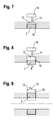
- Figures 7 and 8 Figure 12 shows cross-sectional views of an embodiment which is not part of the invention with an actuating element which is arranged in a socket 10 with socket cavity 12 .
- the actuator may further include an actuator cavity 8 as discussed above.
- the receptacle 10 has a receptacle port 14 for a fluid connection between the receptacle cavity 12 and a pressure generation source 16 .
- the actuating element 2 has a substantially rectangular cross-section, but it can also have a different cross-section, for example one round.
- the actuator of these embodiments, in its non-actuated form 4, may have an elongate shape (ie extend perpendicularly to the plane of the drawing) and be fixed at its ends.
- the actuating member 2 When the receiving cavity 12 is pressurized via the receiving port 14, the actuating member 2 deforms from the non-actuating shape 4 of FIG 7 into the actuation form 6 of 8 .
- the actuating element 2 is fastened at its ends and/or other areas (eg on the inner walls of the receptacle 10) so that the actuating element 2 is not forced out of the receptacle 10.
- the actuating element 2 due to its elasticity, may also move due to a connection with an inside of the receiving 10 returns to its non-actuation form 4.
- FIG. 9 shows a cross-sectional view of an embodiment with an actuating element 2 which is arranged in a receptacle 10 with a receptacle cavity 12 .
- the actuating element 2 can also have an actuating element cavity 8, as explained above.
- the receptacle 10 has a receptacle connection for a fluid connection between the receptacle cavity 12 and a pressure generation source 16 (see, for example, Figures 7 and 8 ) on.
- the actuating element 2 In its non-actuating form 4, the actuating element 2 has an essentially rectangular cross section, but it can also have a different cross section, for example a round one.
- the actuating element 2 of these embodiments is ring-shaped in its non-actuating form 4 (e.g. comparable to an O-ring).
- the receiving cavity 12 is only present in a region of the receiving device 10 , but it can extend like the actuating element 2 in the form of a ring.
- the actuating element 2 When the receiving cavity 12 is pressurized via the first receiving connection, the actuating element 2 deforms from the non-actuating shape 4 shown into an actuating shape 6 indicated by dashed lines. Since the actuating element 2 is ring-shaped, attachment in recording 10 can be dispensed with. When the pressure present in the receiving cavity 12 is released/removed, the actuating element 2 returns to its non-actuating shape 4 due to its elasticity.
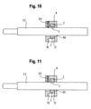
- FIGS 10 and 11 show schematic views of an embodiment for actuating a button T of an e-cigarette.
- This embodiment comprises an essentially ring-shaped holder H with a through-opening DO through which an e-cigarette EZ fits.
- the holder H has a means to secure the e-cigarette EZ in the holder H;
- a threaded pin GS is provided for this purpose, which can be screwed in to secure the e-cigarette EZ and unscrewed to release the same.
- the holder H has a receptacle 10 for an actuating element 2 and a receptacle cavity 12 .
- a receptacle 10 for an actuating element 2 and a receptacle cavity 12 .
- the embodiment of Figures 10 and 11 with the embodiment of 9 comparable.
- FIG. 10 shows the actuating element 2 in its non-actuated form 4, with the receiving cavity 12 not being pressurized or only being pressurized to such an extent that the actuating element 2 is not deformed or is only deformed in such a way that a button T on the e-cigarette is not actuated.
- FIG. 11 shows the actuating element 2 in its actuating form 6, in which case the receiving cavity 12 is pressurized in such a way that the actuating element 2 is deformed in such a way that the button T of the e-cigarette EZ is actuated.
Claims (5)
- Dispositif d'actionnement pour un bouton-poussoir (T) comprenant- un élément d'actionnement élastique (2 ; 2a, 2b) ayant une forme de non-actionnement (4) sans actionner le bouton-poussoir (T) et une forme d'actionnement (6) pour actionner le bouton-poussoir (T),
caractérisé en ce que- l'élément d'actionnement (2 ; 2a, 2b) est annulaire et disposé dans un logement annulaire (10) formé dans un support (H),- il est prévu une cavité de réception (8 ; 8a, 8b ; 12) associée à l'élément d'actionnement (2 ; 2a, 2b), qui est disposé entre un côté intérieur du logement (10) et un côté extérieur de l'élément d'actionnement (2 ; 2a, 2b) et qui peut être sollicitée au moyen d'une pression pneumatique et/ou hydraulique pour amener l'élément d'actionnement (2 ; 2a, 2b) de la forme sans actionnement (4) dans la forme d'actionnement (6),- l'élément d'actionnement (2 ; 2a, 2b) revient à sa forme de non-actionnement (4) en raison de son élasticité lorsque la pression dans la cavité de réception (12) est relâchée/supprimée. - Dispositif d'actionnement selon la revendication précédente, dans lequel le support (H) est de forme annulaire et comprend une ouverture traversante (DO) de section transversale circulaire destinée à recevoir une cigarette électronique (EZ), le logement (10) étant concentrique à l'ouverture traversante (DO) et disposé de telle sorte que l'élément d'actionnement (2 ; 2a, 2b) dans sa forme d'actionnement s'étende dans l'ouverture traversante (DO).
- Dispositif d'actionnement selon l'une des revendications précédentes, dans lequel l'élément d'actionnement (2 ; 2a, 2b) est un joint torique.
- Dispositif d'actionnement selon l'une des revendications précédentes, dans lequel la cavité de réception (12) comprend un raccord de réception pour le raccordement à une source de génération de pression.
- Dispositif d'actionnement selon la revendication précédente, comprenant en outre un moyen de commande pour commander la source de génération de pression.
Applications Claiming Priority (2)
| Application Number | Priority Date | Filing Date | Title |
|---|---|---|---|
| DE102016003048.8A DE102016003048A1 (de) | 2016-03-11 | 2016-03-11 | Vorrichtung und verfahren zur betätigung mechanischer schaltmittel |
| PCT/EP2017/000327 WO2017153051A1 (fr) | 2016-03-11 | 2017-03-12 | Dispositif et procédé d'actionnement de dispositifs de commutation mécaniques |
Publications (2)
| Publication Number | Publication Date |
|---|---|
| EP3427282A1 EP3427282A1 (fr) | 2019-01-16 |
| EP3427282B1 true EP3427282B1 (fr) | 2022-03-02 |
Family
ID=58397975
Family Applications (1)
| Application Number | Title | Priority Date | Filing Date |
|---|---|---|---|
| EP17717622.9A Active EP3427282B1 (fr) | 2016-03-11 | 2017-03-12 | Dispositif et procédé d'actionnement de dispositifs de commutation mécaniques |
Country Status (4)
| Country | Link |
|---|---|
| US (1) | US20210134539A1 (fr) |
| EP (1) | EP3427282B1 (fr) |
| DE (1) | DE102016003048A1 (fr) |
| WO (1) | WO2017153051A1 (fr) |
Families Citing this family (17)
| Publication number | Priority date | Publication date | Assignee | Title |
|---|---|---|---|---|
| US20160345631A1 (en) | 2005-07-19 | 2016-12-01 | James Monsees | Portable devices for generating an inhalable vapor |
| US10279934B2 (en) | 2013-03-15 | 2019-05-07 | Juul Labs, Inc. | Fillable vaporizer cartridge and method of filling |
| US20160366947A1 (en) | 2013-12-23 | 2016-12-22 | James Monsees | Vaporizer apparatus |
| USD825102S1 (en) | 2016-07-28 | 2018-08-07 | Juul Labs, Inc. | Vaporizer device with cartridge |
| US10159282B2 (en) | 2013-12-23 | 2018-12-25 | Juul Labs, Inc. | Cartridge for use with a vaporizer device |
| US10058129B2 (en) | 2013-12-23 | 2018-08-28 | Juul Labs, Inc. | Vaporization device systems and methods |
| USD842536S1 (en) | 2016-07-28 | 2019-03-05 | Juul Labs, Inc. | Vaporizer cartridge |
| US10076139B2 (en) | 2013-12-23 | 2018-09-18 | Juul Labs, Inc. | Vaporizer apparatus |
| FI3491948T4 (fi) | 2013-12-23 | 2024-05-06 | Juul Labs International Inc | Höyrystyslaitejärjestelmiä |
| EP3821735A1 (fr) | 2014-12-05 | 2021-05-19 | Juul Labs, Inc. | Commande de dose graduée |
| EP3413960B1 (fr) | 2016-02-11 | 2021-03-31 | Juul Labs, Inc. | Cartouche de vaporisateur remplissable et procédé de remplissage |
| SG11201806801VA (en) | 2016-02-11 | 2018-09-27 | Juul Labs Inc | Securely attaching cartridges for vaporizer devices |
| US10405582B2 (en) | 2016-03-10 | 2019-09-10 | Pax Labs, Inc. | Vaporization device with lip sensing |
| USD849996S1 (en) | 2016-06-16 | 2019-05-28 | Pax Labs, Inc. | Vaporizer cartridge |
| USD851830S1 (en) | 2016-06-23 | 2019-06-18 | Pax Labs, Inc. | Combined vaporizer tamp and pick tool |
| USD836541S1 (en) | 2016-06-23 | 2018-12-25 | Pax Labs, Inc. | Charging device |
| USD887632S1 (en) | 2017-09-14 | 2020-06-16 | Pax Labs, Inc. | Vaporizer cartridge |
Family Cites Families (7)
| Publication number | Priority date | Publication date | Assignee | Title |
|---|---|---|---|---|
| AT262429B (de) * | 1964-04-27 | 1968-06-10 | Uninorm Anstalt | Fernbetätigbare Schaltvorrichtung |
| FR2057159A5 (fr) * | 1969-08-04 | 1971-05-21 | Arnould Ets | |
| US3900710A (en) * | 1973-10-01 | 1975-08-19 | John Potter | Squeezably actuated general purpose electric switch |
| US4309993A (en) * | 1980-03-06 | 1982-01-12 | Baxter Travenol Laboratories, Inc. | Liquid flow sensing apparatus |
| US4501583A (en) * | 1983-06-15 | 1985-02-26 | Extracorporeal, Inc. | Hemodialysis access monitors |
| TW387559U (en) * | 1999-08-06 | 2000-04-11 | Darfon Electronics Corp | Air-buffered tester for key service life |
| MX2015013513A (es) * | 2013-03-22 | 2016-10-26 | Altria Client Services Llc | Articulo electronico para fumar. |
-
2016
- 2016-03-11 DE DE102016003048.8A patent/DE102016003048A1/de active Pending
-
2017
- 2017-03-12 US US16/084,163 patent/US20210134539A1/en not_active Abandoned
- 2017-03-12 EP EP17717622.9A patent/EP3427282B1/fr active Active
- 2017-03-12 WO PCT/EP2017/000327 patent/WO2017153051A1/fr active Application Filing
Also Published As
| Publication number | Publication date |
|---|---|
| US20210134539A1 (en) | 2021-05-06 |
| WO2017153051A1 (fr) | 2017-09-14 |
| EP3427282A1 (fr) | 2019-01-16 |
| DE102016003048A1 (de) | 2017-09-14 |
Similar Documents
| Publication | Publication Date | Title |
|---|---|---|
| EP3427282B1 (fr) | Dispositif et procédé d'actionnement de dispositifs de commutation mécaniques | |
| DE2437657A1 (de) | Druckabhaengige schalteinrichtung zur verwendung an einem luftreifen | |
| EP3447346A1 (fr) | Soupape, en particulier servosoupape | |
| DE3738075A1 (de) | Stromkreissteuervorrichtung und verfahren zum betaetigen derselben | |
| WO2003021553A1 (fr) | Dispositif pour simuler un instrument chirurgical en forme de tige pour produire un signal de retour | |
| DE1490757B2 (de) | Verfahren zur befestigung von kontaktgebenden elementen insbesondere steckerteilen in einem einstueckigen isolier stoffkoerper eines elektrischen steckverbinders | |
| DE10347936B4 (de) | Ventilanordnung mit einstellbarer Funktion und Verfahren hierfür | |
| DE202009005811U1 (de) | Crimpwerkzeug | |
| DE3432028C2 (fr) | ||
| DE60128356T2 (de) | Mechanische rücksetzvorrichtung für schalter | |
| DE202015106505U1 (de) | Greifer | |
| DE1109762B (de) | Schalter | |
| DE102017201049A1 (de) | Kugelgelenk für ein Fahrzeug | |
| DE60030934T2 (de) | Anordnung zur verstärkung des hubs eines betätigungsorgans eines schalters | |
| DE458460C (de) | Abreisshebel, insbesondere des Unterbrechers von Magnetos | |
| DE102014222284A1 (de) | Bedieneinrichtung | |
| DE2062977C3 (de) | Abstreifvorrichtung | |
| EP3234974B1 (fr) | Dispositif de commande pour un véhicule, en particulier pour un véhicule à passagers | |
| EP2894265B1 (fr) | Dispositif d'actionnement pneumatique | |
| DE2308191B2 (de) | Druckregelventil | |
| DE102017104870B3 (de) | Brause mit einer zwei Antriebselemente aufweisenden Umschaltvorrichtung | |
| DE102013003575A1 (de) | Druck- und drehbetätigbares Bedienelement für ein Kraftfahrzeug | |
| DE4227353A1 (de) | Steuergriffanordnung, insbesondere zur Verwendung mit einer druckmittelbetriebenen Steuergeberanordnung | |
| DE19603921C1 (de) | Druckschalter | |
| DE2913913A1 (de) | Schnappschalter |
Legal Events
| Date | Code | Title | Description |
|---|---|---|---|
| STAA | Information on the status of an ep patent application or granted ep patent |
Free format text: STATUS: UNKNOWN |
|
| STAA | Information on the status of an ep patent application or granted ep patent |
Free format text: STATUS: THE INTERNATIONAL PUBLICATION HAS BEEN MADE |
|
| PUAI | Public reference made under article 153(3) epc to a published international application that has entered the european phase |
Free format text: ORIGINAL CODE: 0009012 |
|
| STAA | Information on the status of an ep patent application or granted ep patent |
Free format text: STATUS: REQUEST FOR EXAMINATION WAS MADE |
|
| 17P | Request for examination filed |
Effective date: 20181011 |
|
| AK | Designated contracting states |
Kind code of ref document: A1 Designated state(s): AL AT BE BG CH CY CZ DE DK EE ES FI FR GB GR HR HU IE IS IT LI LT LU LV MC MK MT NL NO PL PT RO RS SE SI SK SM TR |
|
| AX | Request for extension of the european patent |
Extension state: BA ME |
|
| STAA | Information on the status of an ep patent application or granted ep patent |
Free format text: STATUS: REQUEST FOR EXAMINATION WAS MADE |
|
| DAV | Request for validation of the european patent (deleted) | ||
| DAX | Request for extension of the european patent (deleted) | ||
| GRAP | Despatch of communication of intention to grant a patent |
Free format text: ORIGINAL CODE: EPIDOSNIGR1 |
|
| STAA | Information on the status of an ep patent application or granted ep patent |
Free format text: STATUS: GRANT OF PATENT IS INTENDED |
|
| INTG | Intention to grant announced |
Effective date: 20210713 |
|
| GRAJ | Information related to disapproval of communication of intention to grant by the applicant or resumption of examination proceedings by the epo deleted |
Free format text: ORIGINAL CODE: EPIDOSDIGR1 |
|
| STAA | Information on the status of an ep patent application or granted ep patent |
Free format text: STATUS: REQUEST FOR EXAMINATION WAS MADE |
|
| GRAJ | Information related to disapproval of communication of intention to grant by the applicant or resumption of examination proceedings by the epo deleted |
Free format text: ORIGINAL CODE: EPIDOSDIGR1 |
|
| GRAS | Grant fee paid |
Free format text: ORIGINAL CODE: EPIDOSNIGR3 |
|
| STAA | Information on the status of an ep patent application or granted ep patent |
Free format text: STATUS: GRANT OF PATENT IS INTENDED |
|
| INTC | Intention to grant announced (deleted) | ||
| GRAP | Despatch of communication of intention to grant a patent |
Free format text: ORIGINAL CODE: EPIDOSNIGR1 |
|
| INTG | Intention to grant announced |
Effective date: 20220107 |
|
| GRAA | (expected) grant |
Free format text: ORIGINAL CODE: 0009210 |
|
| STAA | Information on the status of an ep patent application or granted ep patent |
Free format text: STATUS: THE PATENT HAS BEEN GRANTED |
|
| AK | Designated contracting states |
Kind code of ref document: B1 Designated state(s): AL AT BE BG CH CY CZ DE DK EE ES FI FR GB GR HR HU IE IS IT LI LT LU LV MC MK MT NL NO PL PT RO RS SE SI SK SM TR |
|
| REG | Reference to a national code |
Ref country code: GB Ref legal event code: FG4D Free format text: NOT ENGLISH |
|
| REG | Reference to a national code |
Ref country code: CH Ref legal event code: EP Ref country code: AT Ref legal event code: REF Ref document number: 1472925 Country of ref document: AT Kind code of ref document: T Effective date: 20220315 |
|
| REG | Reference to a national code |
Ref country code: DE Ref legal event code: R096 Ref document number: 502017012689 Country of ref document: DE |
|
| REG | Reference to a national code |
Ref country code: IE Ref legal event code: FG4D Free format text: LANGUAGE OF EP DOCUMENT: GERMAN |
|
| REG | Reference to a national code |
Ref country code: LT Ref legal event code: MG9D |
|
| REG | Reference to a national code |
Ref country code: NL Ref legal event code: MP Effective date: 20220302 |
|
| PG25 | Lapsed in a contracting state [announced via postgrant information from national office to epo] |
Ref country code: SE Free format text: LAPSE BECAUSE OF FAILURE TO SUBMIT A TRANSLATION OF THE DESCRIPTION OR TO PAY THE FEE WITHIN THE PRESCRIBED TIME-LIMIT Effective date: 20220302 Ref country code: RS Free format text: LAPSE BECAUSE OF FAILURE TO SUBMIT A TRANSLATION OF THE DESCRIPTION OR TO PAY THE FEE WITHIN THE PRESCRIBED TIME-LIMIT Effective date: 20220302 Ref country code: NO Free format text: LAPSE BECAUSE OF FAILURE TO SUBMIT A TRANSLATION OF THE DESCRIPTION OR TO PAY THE FEE WITHIN THE PRESCRIBED TIME-LIMIT Effective date: 20220602 Ref country code: LT Free format text: LAPSE BECAUSE OF FAILURE TO SUBMIT A TRANSLATION OF THE DESCRIPTION OR TO PAY THE FEE WITHIN THE PRESCRIBED TIME-LIMIT Effective date: 20220302 Ref country code: HR Free format text: LAPSE BECAUSE OF FAILURE TO SUBMIT A TRANSLATION OF THE DESCRIPTION OR TO PAY THE FEE WITHIN THE PRESCRIBED TIME-LIMIT Effective date: 20220302 Ref country code: ES Free format text: LAPSE BECAUSE OF FAILURE TO SUBMIT A TRANSLATION OF THE DESCRIPTION OR TO PAY THE FEE WITHIN THE PRESCRIBED TIME-LIMIT Effective date: 20220302 Ref country code: BG Free format text: LAPSE BECAUSE OF FAILURE TO SUBMIT A TRANSLATION OF THE DESCRIPTION OR TO PAY THE FEE WITHIN THE PRESCRIBED TIME-LIMIT Effective date: 20220602 |
|
| PG25 | Lapsed in a contracting state [announced via postgrant information from national office to epo] |
Ref country code: PL Free format text: LAPSE BECAUSE OF FAILURE TO SUBMIT A TRANSLATION OF THE DESCRIPTION OR TO PAY THE FEE WITHIN THE PRESCRIBED TIME-LIMIT Effective date: 20220302 Ref country code: LV Free format text: LAPSE BECAUSE OF FAILURE TO SUBMIT A TRANSLATION OF THE DESCRIPTION OR TO PAY THE FEE WITHIN THE PRESCRIBED TIME-LIMIT Effective date: 20220302 Ref country code: GR Free format text: LAPSE BECAUSE OF FAILURE TO SUBMIT A TRANSLATION OF THE DESCRIPTION OR TO PAY THE FEE WITHIN THE PRESCRIBED TIME-LIMIT Effective date: 20220603 Ref country code: FI Free format text: LAPSE BECAUSE OF FAILURE TO SUBMIT A TRANSLATION OF THE DESCRIPTION OR TO PAY THE FEE WITHIN THE PRESCRIBED TIME-LIMIT Effective date: 20220302 |
|
| PG25 | Lapsed in a contracting state [announced via postgrant information from national office to epo] |
Ref country code: NL Free format text: LAPSE BECAUSE OF FAILURE TO SUBMIT A TRANSLATION OF THE DESCRIPTION OR TO PAY THE FEE WITHIN THE PRESCRIBED TIME-LIMIT Effective date: 20220302 |
|
| PG25 | Lapsed in a contracting state [announced via postgrant information from national office to epo] |
Ref country code: SM Free format text: LAPSE BECAUSE OF FAILURE TO SUBMIT A TRANSLATION OF THE DESCRIPTION OR TO PAY THE FEE WITHIN THE PRESCRIBED TIME-LIMIT Effective date: 20220302 Ref country code: SK Free format text: LAPSE BECAUSE OF FAILURE TO SUBMIT A TRANSLATION OF THE DESCRIPTION OR TO PAY THE FEE WITHIN THE PRESCRIBED TIME-LIMIT Effective date: 20220302 Ref country code: RO Free format text: LAPSE BECAUSE OF FAILURE TO SUBMIT A TRANSLATION OF THE DESCRIPTION OR TO PAY THE FEE WITHIN THE PRESCRIBED TIME-LIMIT Effective date: 20220302 Ref country code: PT Free format text: LAPSE BECAUSE OF FAILURE TO SUBMIT A TRANSLATION OF THE DESCRIPTION OR TO PAY THE FEE WITHIN THE PRESCRIBED TIME-LIMIT Effective date: 20220704 Ref country code: EE Free format text: LAPSE BECAUSE OF FAILURE TO SUBMIT A TRANSLATION OF THE DESCRIPTION OR TO PAY THE FEE WITHIN THE PRESCRIBED TIME-LIMIT Effective date: 20220302 Ref country code: CZ Free format text: LAPSE BECAUSE OF FAILURE TO SUBMIT A TRANSLATION OF THE DESCRIPTION OR TO PAY THE FEE WITHIN THE PRESCRIBED TIME-LIMIT Effective date: 20220302 |
|
| PG25 | Lapsed in a contracting state [announced via postgrant information from national office to epo] |
Ref country code: IS Free format text: LAPSE BECAUSE OF FAILURE TO SUBMIT A TRANSLATION OF THE DESCRIPTION OR TO PAY THE FEE WITHIN THE PRESCRIBED TIME-LIMIT Effective date: 20220702 Ref country code: AL Free format text: LAPSE BECAUSE OF FAILURE TO SUBMIT A TRANSLATION OF THE DESCRIPTION OR TO PAY THE FEE WITHIN THE PRESCRIBED TIME-LIMIT Effective date: 20220302 |
|
| REG | Reference to a national code |
Ref country code: DE Ref legal event code: R097 Ref document number: 502017012689 Country of ref document: DE |
|
| REG | Reference to a national code |
Ref country code: BE Ref legal event code: MM Effective date: 20220331 |
|
| PLBE | No opposition filed within time limit |
Free format text: ORIGINAL CODE: 0009261 |
|
| STAA | Information on the status of an ep patent application or granted ep patent |
Free format text: STATUS: NO OPPOSITION FILED WITHIN TIME LIMIT |
|
| PG25 | Lapsed in a contracting state [announced via postgrant information from national office to epo] |
Ref country code: MC Free format text: LAPSE BECAUSE OF FAILURE TO SUBMIT A TRANSLATION OF THE DESCRIPTION OR TO PAY THE FEE WITHIN THE PRESCRIBED TIME-LIMIT Effective date: 20220302 Ref country code: LU Free format text: LAPSE BECAUSE OF NON-PAYMENT OF DUE FEES Effective date: 20220312 Ref country code: IE Free format text: LAPSE BECAUSE OF NON-PAYMENT OF DUE FEES Effective date: 20220312 Ref country code: DK Free format text: LAPSE BECAUSE OF FAILURE TO SUBMIT A TRANSLATION OF THE DESCRIPTION OR TO PAY THE FEE WITHIN THE PRESCRIBED TIME-LIMIT Effective date: 20220302 |
|
| 26N | No opposition filed |
Effective date: 20221205 |
|
| PG25 | Lapsed in a contracting state [announced via postgrant information from national office to epo] |
Ref country code: SI Free format text: LAPSE BECAUSE OF FAILURE TO SUBMIT A TRANSLATION OF THE DESCRIPTION OR TO PAY THE FEE WITHIN THE PRESCRIBED TIME-LIMIT Effective date: 20220302 Ref country code: BE Free format text: LAPSE BECAUSE OF NON-PAYMENT OF DUE FEES Effective date: 20220331 |
|
| PGFP | Annual fee paid to national office [announced via postgrant information from national office to epo] |
Ref country code: FR Payment date: 20230321 Year of fee payment: 7 Ref country code: AT Payment date: 20230317 Year of fee payment: 7 |
|
| PGFP | Annual fee paid to national office [announced via postgrant information from national office to epo] |
Ref country code: IT Payment date: 20230331 Year of fee payment: 7 Ref country code: CH Payment date: 20230402 Year of fee payment: 7 |
|
| PG25 | Lapsed in a contracting state [announced via postgrant information from national office to epo] |
Ref country code: HU Free format text: LAPSE BECAUSE OF FAILURE TO SUBMIT A TRANSLATION OF THE DESCRIPTION OR TO PAY THE FEE WITHIN THE PRESCRIBED TIME-LIMIT; INVALID AB INITIO Effective date: 20170312 |
|
| PGFP | Annual fee paid to national office [announced via postgrant information from national office to epo] |
Ref country code: AT Payment date: 20240318 Year of fee payment: 8 |
|
| PG25 | Lapsed in a contracting state [announced via postgrant information from national office to epo] |
Ref country code: MK Free format text: LAPSE BECAUSE OF FAILURE TO SUBMIT A TRANSLATION OF THE DESCRIPTION OR TO PAY THE FEE WITHIN THE PRESCRIBED TIME-LIMIT Effective date: 20220302 Ref country code: CY Free format text: LAPSE BECAUSE OF FAILURE TO SUBMIT A TRANSLATION OF THE DESCRIPTION OR TO PAY THE FEE WITHIN THE PRESCRIBED TIME-LIMIT Effective date: 20220302 |
|
| PGFP | Annual fee paid to national office [announced via postgrant information from national office to epo] |
Ref country code: DE Payment date: 20240321 Year of fee payment: 8 Ref country code: GB Payment date: 20240322 Year of fee payment: 8 |