EP3415287A1 - Führungssystem für versorgungsleitungen und roboter mit führungssystem - Google Patents
Führungssystem für versorgungsleitungen und roboter mit führungssystem Download PDFInfo
- Publication number
- EP3415287A1 EP3415287A1 EP18180303.2A EP18180303A EP3415287A1 EP 3415287 A1 EP3415287 A1 EP 3415287A1 EP 18180303 A EP18180303 A EP 18180303A EP 3415287 A1 EP3415287 A1 EP 3415287A1
- Authority
- EP
- European Patent Office
- Prior art keywords
- deflection
- guide system
- strand
- connection point
- base
- Prior art date
- Legal status (The legal status is an assumption and is not a legal conclusion. Google has not performed a legal analysis and makes no representation as to the accuracy of the status listed.)
- Granted
Links
Images



Classifications
-
- B—PERFORMING OPERATIONS; TRANSPORTING
- B25—HAND TOOLS; PORTABLE POWER-DRIVEN TOOLS; MANIPULATORS
- B25J—MANIPULATORS; CHAMBERS PROVIDED WITH MANIPULATION DEVICES
- B25J19/00—Accessories fitted to manipulators, e.g. for monitoring, for viewing; Safety devices combined with or specially adapted for use in connection with manipulators
-
- B—PERFORMING OPERATIONS; TRANSPORTING
- B25—HAND TOOLS; PORTABLE POWER-DRIVEN TOOLS; MANIPULATORS
- B25J—MANIPULATORS; CHAMBERS PROVIDED WITH MANIPULATION DEVICES
- B25J19/00—Accessories fitted to manipulators, e.g. for monitoring, for viewing; Safety devices combined with or specially adapted for use in connection with manipulators
- B25J19/0025—Means for supplying energy to the end effector
-
- H—ELECTRICITY
- H02—GENERATION; CONVERSION OR DISTRIBUTION OF ELECTRIC POWER
- H02G—INSTALLATION OF ELECTRIC CABLES OR LINES, OR OF COMBINED OPTICAL AND ELECTRIC CABLES OR LINES
- H02G11/00—Arrangements of electric cables or lines between relatively-movable parts
-
- H—ELECTRICITY
- H02—GENERATION; CONVERSION OR DISTRIBUTION OF ELECTRIC POWER
- H02G—INSTALLATION OF ELECTRIC CABLES OR LINES, OR OF COMBINED OPTICAL AND ELECTRIC CABLES OR LINES
- H02G3/00—Installations of electric cables or lines or protective tubing therefor in or on buildings, equivalent structures or vehicles
- H02G3/02—Details
- H02G3/04—Protective tubing or conduits, e.g. cable ladders or cable troughs
- H02G3/0462—Tubings, i.e. having a closed section
- H02G3/0468—Corrugated
-
- Y—GENERAL TAGGING OF NEW TECHNOLOGICAL DEVELOPMENTS; GENERAL TAGGING OF CROSS-SECTIONAL TECHNOLOGIES SPANNING OVER SEVERAL SECTIONS OF THE IPC; TECHNICAL SUBJECTS COVERED BY FORMER USPC CROSS-REFERENCE ART COLLECTIONS [XRACs] AND DIGESTS
- Y10—TECHNICAL SUBJECTS COVERED BY FORMER USPC
- Y10T—TECHNICAL SUBJECTS COVERED BY FORMER US CLASSIFICATION
- Y10T74/00—Machine element or mechanism
- Y10T74/20—Control lever and linkage systems
- Y10T74/20207—Multiple controlling elements for single controlled element
- Y10T74/20305—Robotic arm
- Y10T74/20311—Robotic arm including power cable or connector
Definitions
- the invention relates to a guide system for supply lines for a handling device, in particular for an industrial robot, with a base and a chain, tubular or ribbon-like strand in or on which the supply lines can be arranged, wherein the strand for length compensation in a balancing section in two on a deflection bend interconnected Trumen with one end-side connection point, a stationary to the base of the guide system first connection point and a base movable to the second connection point is guided, the second connection point relative to the first connection point via a travel path between a deflection position, in which Strand is extended, and a reset position in which strand is retracted, is moved back and forth, wherein the guide system has a return device for returning the strand in the return position into which a deflection guide with egg Having a deflecting element on which the deflecting bow is laterally supported for its guidance over the travel path, the deflecting element with at least one travel component in the direction of the travel is arranged movable in a movable manner to
- the invention further relates to a handling device, in particular an industrial robot, with the guide system of the aforementioned type.
- Handling devices such as industrial robots, for example, have at a movable working end a working device as a consumer, which is supplied via supply lines.
- the strands are routed with the supply lines to the structure of the robot along.
- Industrial robots are usually designed for rapid and often very complex movements, which requires a particularly precise management of the supply lines on or in the strand to excessive loading of the strand and thus the supply lines, for example due to entanglements or entanglements on the robot structure or looping the to avoid the strand. This can lead to breakage of the strand and thus the supply line routed through the strand.
- Complex movements require a correspondingly large length compensation in the strand so that it can follow the movements of the industrial robot.
- the DE 10 2009 037 515 A1 discloses a generic guide system in which the deflection guide comprises a deflecting element designed as a molded part, on which the deflecting bend partially slides with the strand.
- the disadvantage here is an increased load on the strand.
- cylindrical rollers are provided, whereby the construction is complicated. Furthermore, the cylindrical rollers lie mechanically unfavorably linearly on the deflection arc and also extend only over a portion of the Guide surface, on which the deflection arc is applied laterally.
- a non-generic guide system for a robot is described with up to six degrees of freedom, in which the strand is held on the Trumen and the deflecting element laterally adjacent deflecting bow, wherein the deflecting necessarily not guided at the base, but by the strand freely movable in the Room is kept.
- the angle enclosed by the trays changes, the area in which the deflecting arc bears against the deflecting element, and thus the forces and moments of force acting on the strand.
- a guide system wherein for recovering a portion of the strand a helically arranged around the strand spring is deflected into the deflection position, which pulls back the strand with retraction of the robot back to the reset position.
- the maximum possible length compensation is determined by the difference of the spring length of the spring in the relaxed and in the compressed state of the spring.
- the object of the invention is to provide a simple constructed generic guide system, by means of which a common strand can be performed inexpensively and safely.
- the deflecting element is designed as a guide roller which is mounted perpendicular to the sheet plane rotatably to the base and on which the deflection arc with a center angle of 180 ° laterally applied
- the return device is a linear Guide rail for the deflection roller, in which the deflection roller engages with its axis of rotation with an armature slidably.
- the method of the deflection roller and thus the method of the deflection roller applied to the deflection roller under confiscation of the strand in its return position can, as already known, take place automatically.
- the strand can be correspondingly released and pulled back via the restoring device in the direction of its return position.
- This could in principle preferably be controlled by means of a motor drive, such as by means of a linear drive or a servomotor.
- preference is given to an automatic reset via a restoring force of a force device introduced into the deflection roller.
- the power device can be designed so that the restoring force generated controlled, for example via the force exerted by the consumer on the strand traction or is preferably regulated.
- the strand can be held towards the consumer in a preferably constant tension, so that an unacceptable sagging of the strand can be avoided.
- the power device can produce the required restoring force in a variety of ways and initiate the deflection roller. This can be done, for example, pneumatically, magnetically, electromagnetically and / or mechanically, in particular spring-mechanically.
- a pneumatic, magnetic and / or mechanical spring may be used, which preferably acts on the deflection roller in a force-effective manner directly or via a force transmission, such as a lever arrangement or gear.
- the deflection roller is arranged under pretension in the return position, wherein the bias has at least one directional component in the direction of the restoring force.
- the deflection arc can be fixed in position to the extent of the acting bias in the return position.
- the restoring force is generated pneumatically, ie by means of a pressure cylinder with an extending pressure piston, then this pneumatically generated restoring force can be easily controlled and regulated.
- This has the advantage that thus the restoring force can be advantageously kept constant. It can thus be controlled or regulated by the height and / or change of the restoring force, the entire movement of the deflection roller. Furthermore, the path of the deflection roller can be limited over here so that corresponding mechanical limit stops are superfluous.
- At least one sensor of a measuring device For detecting the restoring force, the change in position of the deflection roller and / or a contact pressure, with which the deflection arc bears against the deflection roller, at least one sensor of a measuring device can be provided.
- the method of the restoring element depending on the particular location of use of the guide system can be optimized.
- the restoring force can be set according to the travel path.
- endpoints of the travel path of the deflection roller can be optionally set via the control of the restoring force.
- the sensors such as in a demolition of the strand on the consumer, thereby exerting at most greatly reduced tension on the pulley, be acted upon directly on the handling equipment or the industrial robot so that it automatically shuts off.
- an object inadmissible between strand and handling device such that the strand is thereby further stretched and thus exerts an increased tensile force on the pulley
- it can also on the sensory determination of the contact pressure, for example, with which the deflecting abuts the pulley, an emergency shutdown the handling device or the industrial robot done.
- the respective sensors for the detection of the restoring force, the change in location of the deflection roller and / or the contact pressure can, adapted to the respective task, be formed in the usual way.
- a measured value assumption can be made translationally or rotationally.
- conventional position sensors of suitable design can be used. These can be, for example, optical, capacitive, inductive, magneto-inductive, magnetostrictive, electrical, for example, according to the eddy current method, or work magnetically on the Hall effect.
- the distance measurement can be an absolute distance measurement starting from a zero point or, as an incremental path measurement, which is preferred, measuring only the positive or negative increases in the distance traveled.
- a non-contact detection of the change in location of the deflection roller is preferred, as it is possible, for example, in a capacitive, inductive, magneto-inductive or magneto-strictive manner.
- potentiometers i. Rotary potentiometer when detecting a rotary movement and linear potentiometer when detecting a linear movement. In each case, an incremental path measurement is preferred since no zero-point control is provided for this purpose.
- the part of the strand, which does not belong to the compensation section, can additionally be supported and guided by means of at least one further guide element.
- a conventional guide ring with sliding friction-reducing coating for example made of Teflon are used, through which the strand is slidably guided guided and which is mounted on the outer structure of the handling device preferably adjustable.
- the guide system may include a housing with a cover for protection.
- the housing may have the base as a housing bottom to which the lid is pivotally hinged. Furthermore, for mounting on the handling device preferably at the base holding means may be provided.
- the guide system can thus be completely prefabricated as a module with the compensation section, the return device and the power device and possibly with the measuring device and control unit.
- These modules can be stored in different versions. This can be used, for example, for converting the handling device bez. of the industrial robot, a modular management system can be replaced or supplemented by another management system adapted to the conversion.
- Sets of individual assemblies of the guidance system may be provided. It may be advantageous to include individual or all assemblies in different interpretations in the set.
- the guide system 1 is designed for supply lines not shown here for a designed here as an industrial robot I handling device.
- the guide system 1 has here a plate-shaped base 2 and a chain-like strand 3 here with a circular cross section and an interior 3.1, in which the supply lines, not shown here, can be arranged.
- the guide system 1 is, as in the Figures 6a-c illustrates, here designed to lead supply lines via the strand 3 to a consumer, not shown here, arranged at the end of an arm A of the industrial robot I, wherein the arm A is variable with respect to its length.
- the second connection point 9 is relative to the first connection point 8 via a travel path V between a deflection position (FIG. FIGS. 3, 4 and 5 ) in which the strand 3 is extended and a reset position ( FIGS. 1, 2 and 6 ), in which the strand 3 is retracted, moved back and forth.
- the guide system 1 further comprises a return device 10 for the automatic return of the strand 3 to the return position here.
- the return device 10 has a deflection guide 11 with a deflecting element 12.
- the deflecting element 12 is formed as a deflection roller 13, wherein the deflection roller 13 is arranged about a rotation axis d perpendicular to a sheet plane E, in which the deflection arc 5 is arranged, is freely rotatably mounted.
- At the guide roller 13 of the deflection arc 5 is to his leadership on the travel v of the second connection point 9 rollable laterally.
- the deflecting element 12 is arranged such that it can move in a mobile manner at least with a path component in the direction of the travel path v to the base 2 between the deflecting position and the return position.
- the travel v of the second connection point 9 is twice as large as the path w, which passes through the deflection roller 13 during the process of the first connection point 9.
- a maximum travel v can be set via the path w of the deflection roller.
- the deflection roller 13 has a lateral guide surface 14 for the deflection arc 5.
- the lateral guide surface 14 is adapted to the outer contour of the deflection arc 5, i. here, corresponding to the circular cross section of the strand 3, concave semicircular.
- a force device 17 is provided for generating and introducing a restoring force into the deflecting element 12.
- the deflecting element 12 is moved on a linear path w, which is arranged parallel to the travel v of the second drive point 9.
- the guide roller 13 engages with its axis of rotation d in a guide rail 21 with a not visible here anchor slidably.
- a pneumatic pressure cylinder 22 is provided which engages with its plunger 23 at the not apparent here anchor the D-axis d.
- the printing cylinder 20 is, which is not shown here, over the control and regulation unit controllable.
- control of the printing cylinder 22 is coordinated with the movement of the arm A of the robot E and / or controlled or regulated by a pressure measurement of the contact pressure of the deflection arc 5 on the deflecting element 12.
- the limits of the path w for the process of the deflection element 12 can also be adjusted.
- a hinged at the base 2 hinged lid is provided.
- Both strands 6, 7 of the compensation section are at the ends for connection, for example, to further parts of the strand 3 or, as in FIGS. 6 , for connection to a working end B of the arm A, externally accessible from base 2 and lid accessible openings.
- Both openings 25 frame each one stationary to the base 2 ring-like guide member 26, wherein the guide member 26 serves for the first connection point 8 at the same time as a stationary support, while the other guide member 26 is formed as a sliding ring, through which the strand 7 with the movable connection point 9 slidably is guided.
- the base 2 holding means 27 are provided on the underside.
Landscapes
- Engineering & Computer Science (AREA)
- Robotics (AREA)
- Mechanical Engineering (AREA)
- Architecture (AREA)
- Civil Engineering (AREA)
- Structural Engineering (AREA)
- Manipulator (AREA)
- Rollers For Roller Conveyors For Transfer (AREA)
Abstract
Description
- Die Erfindung betrifft ein Führungssystem für Versorgungsleitungen für ein Handhabungsgerät, insbesondere für einen Industrieroboter, mit einer Basis und einem ketten-, schlauch- oder bandartigen Strang, in oder an dem die Versorgungsleitungen anordenbar sind, wobei der Strang zum Längenausgleich in einem Ausgleichsabschnitt in zwei über einen Umlenkbogen miteinander verbundenen Trumen mit jeweils einem endseitigen Anschlusspunkt, einem zu der Basis des Führungssystems stationären ersten Anschlusspunkt und einem zu der Basis bewegbaren zweiten Anschlusspunkt, geführt angeordnet ist, der zweite Anschlusspunkt relativ zum ersten Anschlusspunkt über einen Verfahrweg zwischen einer Auslenkposition, in der der Strang ausgefahren ist, und einer Rückstellposition, in der Strang eingefahren ist, hin und her verfahrbar ist, wobei das Führungssystem eine Rückstellvorrichtung zur Rückstellung des Stranges in die Rückstellposition hinein aufweist, die eine Umlenkungsführung mit einem Umlenkelement aufweist, an dem sich der Umlenkbogen zu seiner Führung über den Verfahrweg seitlich abstützt, das Umlenkelement mit zumindest einer Wegkomponente in Richtung des Verfahrweges ortsveränderlich zur Basis zwischen der Auslenkposition und der Rückstellposition hin und her verfahrbar angeordnet ist und eine seitliche Führungsfläche für den Umlenkbogen aufweist, die sich zumindest etwa senkrecht zu einer Bogenebene erstreckt, in der der Umlenkbogen angeordnet ist.
- Die Erfindung betrifft ferner ein Handhabungsgerät, insbesondere einen Industrieroboter, mit dem Führungssystem der vorstehend genannten Art.
- Handhabungsgeräte, wie Industrieroboter, weisen beispielsweise an einem bewegbaren Arbeitsende ein Arbeitsgerät als Verbraucher auf, der über Versorgungsleitungen versorgt wird. In der Regel werden die Stränge mit den Versorgungsleitungen an der Struktur der der Roboter entlang geführt. Industrieroboter sind in der Regel für rasche und häufig sehr komplexe Bewegungsabläufe ausgelegt, welches eine besonders präzise Führung der Versorgungsleitungen an oder in dem Strang erfordert, um eine übermäßige Belastung des Stranges und damit der Versorgungsleitungen beispielsweise infolge von Verhakungen oder Verwicklungen an der Roboterstruktur oder Schlaufenbildung der des Stranges zu vermeiden. Dies kann zum Bruch des Stranges und damit der durch den Strang geführten Versorgungsleitung führen. Komplexe Bewegungsabläufe erfordern einen entsprechend großen Längenausgleich bei dem Strang, damit dieser den Bewegungsabläufen des Industrieroboters folgen kann. Im Stand der Technik wird vorgeschlagen, eine Teillänge des Stranges aus der Auslenkungsposition in die Rückstellposition mittels einer Rückstellvorrichtung zurückzubringen.
- Die
DE 10 2009 037 515 A1 offenbart ein gattungsgemäßes Führungssystem, bei dem die Umlenkführung ein als Formteil ausgebildetes Umlenkelement aufweist, an dem der Umlenkbogen mit Verfahren des Stranges partiell abgleitet. Nachteilig hierbei ist eine erhöhte Belastung des Stranges. Zur Verminderung der mechanischen Belastung sind kleine Zylinderrollen vorgesehen, wodurch die Konstruktion aufwändig wird. Ferner liegen die Zylinderrollen mechanisch ungünstig linienhaft an dem Umlenkbogen an und erstrecken sich zudem lediglich über einen Teilbereich der Führungsfläche, an der der Umlenkbogen seitlich anliegt. - In der
WO 97/39505 A1 - In der
WO2005/123350A1 wird ein Führungssystem beschrieben, wobei zur Rückstellung eines Abschnittes des Stranges eine um den Strang wendelförmig angeordnete Feder in die Auslenkposition hinein ausgelenkt wird, die den Strang mit Zurückfahren des Roboters wieder in die Rückstellposition zurückzieht. Der maximal mögliche Längenausgleich wird durch die Differenz der Federlänge der Feder im entspannten und im zusammengedrückten Zustand der Feder bestimmt. - Bei einem Führungssystem gemäß der
DE 20 2010 007 251 U1 greift die Rückstellvorrichtung aufwendig über ein federvorgespanntes Seil an einem als Anschlussstück ausgebildetem Kettenglied kraftwirksam an, um den dort kettenförmigen Strang innerhalb eines Gehäuses in die Rückstellposition hinein zurückzuziehen. - In der
DE 10 2007 018 543 A1 wird der Strang vom erste Anschlusspunkt in einem Drehhebel radial nach außen zu einem Anschlusselement geführt, das mit Drehung des Drehhebels unter Abwicklung eines halbkreisförmigen Umlenkbogens auf einem Kreisbogen geführt wird. Zur Rückholung ist auch hier eine den Strang wendelförmig umschließende Feder vorgesehen. Nachteilig ist neben der Verdrillung der Leitungen im ersten Anschlusspunkt der relativ geringe mögliche Längenausgleich des Stranges. - Aufgabe der Aufgabe der Erfindung ist, ein einfach konstruiertes gattungsgemäßes Führungssystem bereitzustellen, mittels dessen ein üblicher Strang unaufwändig und sicher geführt werden kann.
- Die Aufgabe wird bei einem Führungssystem der eingangs beschriebenen Art erfindungsgemäß dadurch gelöst, dass das Umlenkelement als Umlenkrolle ausgebildet ist, die senkrecht zur Bogenebene drehbar zur Basis gelagert ist und an der der Umlenkbogen mit einem Mittelpunktswinkel von 180° seitlich anliegt, und die Rückstellvorrichtung eine lineare Führungsschiene für die Umlenkrolle aufweist, in die die Umlenkrolle mit ihrer Drehachse mit einem Anker gleitverschieblich eingreift.
- Das Verfahren der Umlenkrolle und damit das Verfahren des an der Umlenkrolle anliegenden Umlenkbogens unter Einziehung des Stranges in seine Rückstellposition hinein kann, wie bereits bekannt, automatisch erfolgen. Wenn der durch die Versorgungsleitung versorgte Verbraucher an der Handmaschine bzw. an dem Roboter zurück verfährt, kann der Strang entsprechend freigegeben und über die Rückstellvorrichtung in Richtung seiner Rückstellposition zurück gezogen werden. Dies könnte im Prinzip vorzugsweise geregelt mittels eines motorischen Antriebes, wie mittels eines Linearantriebes oder eines Stellmotors, erfolgen. Bevorzugt wird jedoch eine automatische Rückstellung über eine in die Umlenkrolle eingeleitete Rückstellkraft einer Kraftvorrichtung. Hierbei kann die Kraftvorrichtung so ausgelegt sein, dass die erzeugte Rückstellkraft beispielsweise über den von dem Verbraucher auf den Strang ausgeübte Zugkraft gesteuert oder vorzugsweise geregelt wird. Damit kann der Strang zu dem Verbraucher hin in einer vorzugsweise konstanten Zugspannung gehalten werden, so dass ein unzulässiges Durchhängen des Stranges vermieden werden kann.
- Die Kraftvorrichtung kann auf verschiedenste Weise die erforderliche Rückstellkraft erzeugen und in die Umlenkrolle einleiten. Dieses kann beispielsweise pneumatisch, magnetisch, elektromagnetisch und/oder mechanisch, hier insbesondere federmechanisch, erfolgen. Hierzu kann beispielsweise eine pneumatische, magnetische und/oder mechanische Feder eingesetzt werden, die vorzugsweise unmittelbar oder über eine Kraftübersetzung, wie Hebelanordnung oder Getriebe, auf die Umlenkrolle kraftwirksam einwirkt.
- In einer bevorzugten Ausbildung des Führungssystems ist vorgesehen, dass die Umlenkrolle unter Vorspannung in der Rückstellposition angeordnet ist, wobei die Vorspannung zumindest mit einer Richtungskomponente in Richtung der Rückstellkraft weist. Damit kann der Umlenkbogen im Umfange der wirkenden Vorspannung in der Rückholposition lagefixiert werden. Der Einsatz einer rein mechanischen Feder zur Erzeugung der Rückstellkraft hat den Vorteil, dass dieses einfach und mechanisch robust bewerkstelligbar ist.
- Wird beispielsweise die Rückstellkraft auf pneumatischem Wege, d.h. mittels eines Druckzylinders mit ausfahrendem Druckkolben erzeugt, so kann diese pneumatisch erzeugte Rückstellkraft unaufwändig gesteuert und geregelt werden. Dies hat den Vorteil, dass damit die Rückstellkraft vorteilhaft konstant gehalten werden kann. Es kann somit die gesamte Bewegung der Umlenkrolle über die Höhe und/oder Änderung der Rückstellkraft gesteuert oder geregelt werden. Ferner kann über hierüber der Weg der Umlenkrolle begrenzt werden, so dass entsprechende mechanische Endanschläge überflüssig sind.
- Zur Erfassung der Rückstellkraft, der Ortsveränderung der Umlenkrolle und/oder eines Anpressdruckes, mit dem der Umlenkbogen an der Umlenkrolle anliegt, kann zumindest ein Sensor einer Messvorrichtung vorgesehen sein. Hierdurch kann einerseits das Verfahren des Rückstellelementes, abhängig von dem jeweiligen Einsatzort des Führungssystems, optimiert werden. So kann beispielsweise bei Änderung des komplizierten Bewegungsablaufes, insbesondere bei einer Änderung der Verfahrgeschwindigkeit des Verbrauchers, entsprechend die Rückstellkraft über den Verfahrweg eingestellt werden. Ferner können hierüber Endpunkte des Verfahrweges der Umlenkrolle über die Steuerung der Rückstellkraft wahlweise eingestellt werden. Ferner kann über die Sensoren, wie beispielsweise bei einem Abriss des Stranges am Verbraucher, der dadurch höchstens stark verminderte Zugkraft auf die Umlenkrolle ausübt, unmittelbar auf das Handhabungsgeräte bzw. den Industrieroboter so eingewirkt werden, dass dieser automatisch abschaltet. Wird beispielsweise ein Gegenstand unzulässig zwischen Strang und Handhabungsgerät derart, dass der Strang hierdurch weiter gespannt wird und somit eine erhöhte Zugkraft auf die Umlenkrolle ausübt, so kann auch über die sensorische Ermittlung beispielsweise des Anpressdruckes, mit dem der Umlenkbogen an der Umlenkrolle anliegt, eine Notausschaltung des Handhabungsgerätes bzw. des Industrieroboters erfolgen. Die jeweiligen Sensoren zur die Erfassung der Rückstellkraft, der Ortsveränderung der Umlenkrolle und/oder des Anpressdruckes können, angepasst an die jeweilige Aufgabe, in üblicher Weise ausgebildet sein. Beispielsweise können zur Erfassung der Ortsveränderung der Umlenkrolle Positionssensoren für lineare Wegmessung oder Winkelsensoren der Winkelmessung bei bogenförmiger Ortsveränderung der Umlenkrolle vorgesehen sein. Demnach kann eine Messwertannahme translatorisch oder rotatorisch erfolgen. Hierbei können übliche Positionssensoren geeigneter Bauart in Frage kommen. Diese können beispielsweise lichtoptisch, kapazitiv, induktiv, magnet-induktiv, magneto-striktiv, elektrisch, beispielsweise nach dem Wirbelstromverfahren, oder magnetisch nach dem Halleffekt arbeiten. Dabei kann die Wegmessung als absolute Wegmessung von einem Nullpunkt ausgehen oder als inkrementale Wegmessung, was bevorzugt ist, lediglich die positiven oder negativen Zuwächse des zurückgelegten Weges messen.
- Allgemein wird eine berührungslose Erfassung der Ortsveränderung der Umlenkrolle bevorzugt, wie sie beispielsweise auf kapazitive, induktive, magneto-induktive oder magneto-striktive Weise möglich ist. Besonders bevorzugt werden jedoch Potentiometer, d.h. Drehpotentiometer bei Erfassung einer Drehbewegung und Linearpotentiometer bei Erfassung einer lineare Bewegung. Hierbei wird jeweils eine inkrementale Wegmessung bevorzugt, da hierzu keine Nullpunktansteuerung vorgesehen ist.
- Der Teil des Stranges, der nicht zu dem Ausgleichsabschnitt gehört, kann zusätzlich mittels zumindest eines weiteren Führungselementes abgestützt und geführt werden. Hierzu kann ein üblicher Führungsring mit Gleitreibung verringernder Beschichtung beispielsweise aus Teflon zum Einsatz kommen, durch den der Strang geführt gleitverschieblich angeordnet ist und der an der Außenstruktur des Handhabungsgerätes vorzugsweise einstellbar montiert ist.
- Das Führungssystem kann ein Gehäuse mit Deckel zum Schutz aufweisen. Das Gehäuse kann die Basis als Gehäuseboden aufweisen, an den der Deckel klappbar angelenkt ist. Ferner können zur Montage an dem Handhabungsgerät vorzugsweise an der Basis Halterungsmittel vorgesehen sein.
- Das Führungssystem kann somit als Modul mit dem Ausgleichsabschnitt, der Rückstellvorrichtung und der Kraftvorrichtung sowie eventuell mit der Messvorrichtung und Steuerungs- und Regelungseinheit vollständig vorgefertigt werden. Diese Module können in verschiedenen Ausführungen bevorratet werden. Damit kann beispielsweise zum Umrüsten des Handhabungsgerätes bez. des Industrieroboters ein modulares Führungssystem durch ein der Umrüstung angepasstes anderes Führungssystem ausgetauscht oder ergänzt werden. Es können Sets mit einzelnen Baugruppen des Führungssystems bereitgestellt werden. Es können einzelne oder alle Baugruppen vorteilhaft in unterschiedlichen Auslegungen in dem Set enthalten sein.
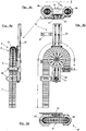
- Die vorliegende Erfindung wird im Folgenden anhand eines in der Zeichnung dargestellten Ausführungsbeispiels des Führungssystems bzw. des Handhabungsgerätes mit dem Führungssystem näher erläutert. In der Zeichnung zeigen:
-
Figuren 1a und 1b sowie 2a und 2b jeweils eine Ansicht eines Ausführungsbeispiels des Führungssystems mit der Umlenkrolle in der Rückstellposition -
Figuren 3a und 3b sowie 4a und 4b jeweils eine Ansicht des Ausführungsbeispiels des Führungssystems gemäß denFiguren 1 und 2 , jedoch mit der Umlenkrolle in der Auslenkposition -
Figuren 5a bis 5d jeweils eine Ansicht des Ausführungsbeispiels des Führungssystems gemäß denFiguren 3 und 4 und -
Figuren 6a bis 6c jeweils eine Ansicht eines Industrieroboters mit dem Führungssystem gemäßFiguren 1 und 2 . - Das Führungssystem 1 ist für hier nicht weiter dargestellte Versorgungsleitungen für ein hier als Industrieroboter I ausgebildetes Handhabungsgerät ausgelegt. Das Führungssystem 1 weist hier eine hier plattenförmige Basis 2 und einen hier kettenförmigen Strang 3 mit kreisrundem Querschnitt und einem Innenraum 3.1 auf, in dem die hier nicht dargestellte Versorgungsleitungen anordenbar sind. Das Führungssystem 1 ist, wie in den
Figuren 6a-c verdeutlicht, hier ausgelegt, Versorgungsleitungen über den Strang 3 zu einem hier nicht dargestellten, am Ende eines Armes A des Industrieroboter I angeordneten Verbrauchers hinzuführen, wobei der Arm A bezüglich seiner Länge veränderbar ist. Zum Längenausgleich ist der Strang 3 in einem hier allein den Strang 3 darstellenden Ausgleichsabschnitt 4 in zwei über einen Umlenkbogen 5 miteinander verbundenen Trumen 6, 7 mit jeweils einem endseitigen Anschlusspunkt, einen zu der Basis 2 des Führungssystems 1 stationärem ersten Anschlusspunkt 8 und einem zu der Basis 2 bewegbaren zweiten Anschlusspunkt 9, geführt, angeordnet ist. Der zweite Anschlusspunkt 9 ist relativ zum ersten Anschlusspunkt 8 über einen Verfahrweg V zwischen einer Auslenkposition (Figuren 3, 4 und5 ) in der der Strang 3 ausgefahren ist und einer Rückstellposition (Figuren 1, 2 und6 ), in der der Strang 3 eingefahren ist, hin- und her verfahrbar. - Das Führungssystem 1 weist ferner eine Rückstellvorrichtung 10 zur hier automatischen Rückstellung des Stranges 3 in die Rückholposition hinein auf. Die Rückstellvorrichtung 10 weist eine Umlenkführung 11 mit einem Umlenkelement 12 auf. Das Umlenkelement 12 ist als Umlenkrolle 13 ausgebildet, wobei die Umlenkrolle 13 um eine Drehachse d senkrecht zu einer Bogenebene E, in der der Umlenkbogen 5 angeordnet ist, frei drehbar gelagert ist. An der Umlenkrolle 13 liegt der Umlenkbogen 5 zu seiner Führung über den Verfahrweg v des zweiten Anschlusspunktes 9 rollverschieblich seitlich an. Das Umlenkelement 12 ist zumindest mit einer Wegkomponente in Richtung des Verfahrweges v ortsveränderlich zur Basis 2 zwischen der Auslenkposition und der Rückholposition hin- und her verfahrbar angeordnet. Wie aus der Mechanik von Umlenkrollen bekannt und in
Figur 3b skizzenhaft angedeutet, ist der Verfahrweg v des zweiten Anschlusspunktes 9 doppelt so groß wie der Weg w, den die Umlenkrolle 13 beim Verfahren des ersten Anschlusspunktes 9 durchläuft. Somit kann über den Weg w der Umlenkrolle zugleich ein maximaler Verfahrweg v eingestellt werden. - Die Umlenkrolle 13 weist eine seitliche Führungsfläche 14 für den Umlenkbogen 5 auf. Die seitliche Führungsfläche 14 ist der Außenkontur des Umlenkbogens 5 angepasst, d.h. hier, entsprechend dem kreisförmigen Querschnitt des Stranges 3, konkav halbkreisförmig ausgebildet.
- Zur automatischen Rückstellung des Umlenkelementes 12 in seine Rückstellposition hinein ist eine Kraftvorrichtung 17 zur Erzeugung und Einleitung einer Rückstellkraft in das Umlenkelement 12 vorgesehen.
- Wie aus den
Figuren 1 bis 5 hervorgeht, wird das Umlenkelement 12 auf einem linearen Weg w verfahren, der parallel zum Verfahrweg v des zweiten Antriebspunktes 9 angeordnet ist. Hierzu greift die Umlenkrolle 13 mit seiner Drehachse d in eine Führungsschiene 21 mit einem hier nicht sichtbaren Anker gleitverschieblich ein. Zur Einhaltung der Rückholkraft ist hier ein pneumatischer Druckzylinder 22 vorgesehen, der mit seinem Druckstempel 23 an dem hier nicht ersichtlichen Anker der D-Achse d angreift. Der Druckzylinder 20 ist, was hier nicht dargestellt ist, über die Steuerungs- und Regelungseinheit steuerbar. Somit kann, was ebenfalls den Figuren nicht entnehmbar ist, die Ansteuerung des Druckzylinders 22 mit der Bewegung des Armes A des Roboters E koordiniert und/oder über eine Druckmessung des Anpressdruckes des Umlenkbogens 5 an dem Umlenkelement 12 gesteuert oder geregelt werden. Über eine Verfahrlänge des Druckstempels 23 aus dem Druckzylinder 22 kann zudem die Begrenzungen des Weges w für das Verfahren des Umlenkelementes 12 eingestellt werden. - Bei dem in der Zeichnung dargestellten Ausführungsbeispiel des Führungssystems 1 ist ein an der Basis 2 klappbar angelenkter Deckel vorgesehen. Beide Trume 6, 7 des Ausgleichsabschnitts sind endseitig zum Anschluss beispielsweise an weitere Teile des Stranges 3 oder, wie in
Figuren 6 , zum Anschluss an ein Arbeitsende B des Armes A, von außen an von Basis 2 und Deckel begrenzte Öffnungen erreichbar. Beide Öffnungen 25 umrahmen jeweils ein zur Basis 2 stationäres ringartiges Führungselement 26, wobei das Führungselement 26 für den ersten Anschlusspunkt 8 zugleich als stationäre Halterung dient, während das andere Führungselement 26 als Gleitring ausgebildet ist, durch welchen das Trum 7 mit dem bewegbaren Anschlusspunkt 9 gleitverschieblich geführt ist. Zur Festlegung des Führungssystems 1 an dem Industrieroboter I sind unterseitig der Basis 2 Halterungsmittel 27 vorgesehen. -
- 1
- Führungssystem
- 2
- Basis
- 3
- Strang
- 3.1
- Innenraum
- 4
- Ausgleichsabschnitt
- 5
- Umlenkbogen
- 6
- Trum
- 7
- Trum
- 8
- erster Anschlusspunkt
- 9
- zweiter Anschlusspunkt
- 10
- Rückstellvorrichtung
- 11
- Umlenkführung
- 12
- Umlenkelement
- 13
- Umlenkrolle
- 14
- Führungsfläche
- 17
- Kraftvorrichtung
- 21
- Führungsschiene
- 22
- Druckzylinder
- 23
- Druckstempel
- 26
- Führungselement
- 27
- Halterungsmittel
- A
- Arm
- B
- Arbeitsende
- E
- Bogenebene
- I
- Industrieroboter
- d
- Drehachse
- v
- Verfahrweg
- w
- Weg
Claims (13)
- Führungssystem (1) für Versorgungsleitungen für ein Handhabungsgerät, insbesondere für einen Industrieroboter (I), mit einer Basis (2) und einem ketten-, schlauch- oder bandartigen Strang (3), in oder an dem die Versorgungsleitungen anordenbar sind, wobei der Strang (3) zum Längenausgleich in einem Ausgleichsabschnitt (4) in zwei über einen Umlenkbogen (5) miteinander verbundenen Trumen (6, 7) mit jeweils einem endseitigen Anschlusspunkt, einem zu der Basis (2) des Führungssystems (1) stationären ersten Anschlusspunkt (8) und einem zu der Basis (2) bewegbaren zweiten Anschlusspunkt (9), geführt angeordnet ist, der zweite Anschlusspunkt (9) relativ zum ersten Anschlusspunkt (8) über einen Verfahrweg (V) zwischen einer Auslenkposition, in der der Strang (3) ausgefahren ist, und einer Rückstellposition, in der der Strang (3) eingefahren ist, hin und her verfahrbar ist, wobei das Führungssystem (1) eine Rückstellvorrichtung (10) zur Rückstellung des Stranges (3) in die Rückstellposition hinein aufweist, die eine Umlenkungsführung (11) mit einem Umlenkelement (12) aufweist, an dem sich der Umlenkbogen (5) zu seiner Führung über den Verfahrweg (v) seitlich abstützt, das Umlenkelement (12) mit zumindest einer Wegkomponente in Richtung des Verfahrweges (v) ortsveränderlich zur Basis (2) zwischen der Auslenkposition und der Rückstellposition hin und her verfahrbar angeordnet ist, und eine seitliche Führungsfläche (14) für den Umlenkbogen (5) aufweist, die sich zumindest etwa senkrecht zu einer Bogenebene (E) erstreckt, in der der Umlenkbogen (5) angeordnet ist, dadurch gekennzeichnet, dass das Umlenkelement (12) als Umlenkrolle (13) ausgebildet ist, die senkrecht zur Bogenebene (E) drehbar zur Basis (2) gelagert ist und an der der Umlenkbogen (5) mit einem Mittelpunktswinkel von 180° seitlich anliegt, und die Rückstellvorrichtung (10) eine lineare Führungsschiene (21) für die Umlenkrolle (13) aufweist, in die die Umlenkrolle (13) mit ihrer Drehachse (d) mit einem Anker gleitverschieblich eingreift.
- Führungssystem nach Anspruch 1, dadurch gekennzeichnet, dass die Rückstellvorrichtung (10) zur automatischen Rückstellung eine Kraftvorrichtung (17) zur Einleitung einer Rückstellkraft in die Umlenkrolle (13) aus der Auslenkposition in die Rückstellposition hinein aufweist.
- Führungssystem nach Anspruch 2, dadurch gekennzeichnet, dass die Einleitung der Rückstellkraft pneumatisch, magnetisch, elektromagnetisch und/oder mechanisch, insbesondere federmechanisch erfolgt.
- Führungssystem nach einem der Ansprüche 1 bis 3, dadurch gekennzeichnet, dass die Umlenkrolle (13) unter Vorspannung in der Rückstellposition angeordnet ist.
- Führungssystem nach einem der Ansprüche 1 bis 4, dadurch gekennzeichnet, dass das Trum (7) mit dem zweiten Anschlusspunkt (9) durch ein zur Basis (2) stationäres Führungselement (26), insbesondere durch einen Gleitring, unter gleit- oder rollverschieblicher seitlichen Anlage an demselben geführt angeordnet ist.
- Führungssystem nach einem der Ansprüche 1 bis 5, dadurch gekennzeichnet, dass die Höhe und/oder Änderung der Rückstellkraft gesteuert oder geregelt ist.
- Führungssystem nach einem der Ansprüche 1 bis 6, dadurch gekennzeichnet, dass eine Messvorrichtung mit einem Sensor zur Erfassung der Rückstellkraft, der Ortsveränderung der Umlenkrolle (13) und/oder eines Anpressdruckes, mit dem der Umlenkbogen (5) an der Umlenkrolle (13) anliegt, vorgesehen ist.
- Führungssystem nach Anspruch 7, dadurch gekennzeichnet, dass die Erfassung der Ortsveränderung der Umlenkrolle (13) berührungslos erfolgt.
- Führungssystem nach Anspruch 7 oder 8, dadurch gekennzeichnet, dass der Sensor ein Signal zur Steuerung oder Regelung der Rückstellkraft erzeugt.
- Führungssystem nach einem der Ansprüche 7 bis 9, dadurch gekennzeichnet, dass die Sensoren ein Signal erzeugen, dass zur Steuerung des Handhabungsgerätes, insbesondere zur Notabschaltung des Handhabungsgerätes, einsetzbar ist.
- Führungssystem nach einem der Ansprüche 1 bis 10, dadurch gekennzeichnet, dass es ein Gehäuse mit Deckel zum Schutz aufweist.
- Handhabungsgerät, insbesondere Industrieroboter (I), mit einem Führungssystem (1) gemäß einem der Ansprüche 1 bis 11 für Versorgungsleitungen mit einer Basis (2) und einem ketten-, schlauch- oder bandartigen Strang (3), in oder an dem die Versorgungsleitungen anordenbar sind.
- Handhabungsgerät, insbesondere Industrieroboter (I), nach Anspruch 12, wobei der Strang (3) zum Längenausgleich in einem Ausgleichsabschnitt (4) in zwei über einen Umlenkbogen (5) miteinander verbundenen Trumen (6, 7) mit jeweils einem endseitigen Anschlusspunkt, einem zu der Basis (2) des Führungssystems (1) stationären ersten Anschlusspunkt (8) und einem zu der Basis (2) bewegbaren zweiten Anschlusspunkt (9), geführt angeordnet ist, der zweite Anschlusspunkt (9) relativ zum ersten Anschlusspunkt (8) über einen Verfahrweg (v) zwischen einer Auslenkposition, in der der Strang (3) ausgefahren ist, und einer Rückstellposition, in der Strang (3) eingefahren ist, hin und her verfahrbar ist, das Führungssystem (1) eine Rückstellvorrichtung (10) zur Rückstellung des Stranges (3) in die Rückstellposition hinein aufweist, die Rückstellvorrichtung (10) eine Umlenkungsführung (11) mit einer Umlenkrolle (13) aufweist, an der sich der Umlenkbogen (5) zu seiner Führung über den Verfahrweg (v) seitlich abstützt, und das Führungssystem (1) eine Messvorrichtung mit einem Messsignale erzeugenden Sensor zur Erfassung der Rückstellkraft, der Ortsveränderung der Umlenkrolle (13) und/oder eines Anpressdruckes, mit dem der Umlenkbogen (5) an der Umlenkrolle (13) anliegt, aufweist, dadurch gekennzeichnet , dass die Messsignale mit einer vorgesehenen Steuerung oder Regelung des Handhabungsgerätes bzw. Industrieroboters (I) verknüpfbar sind.
Applications Claiming Priority (3)
| Application Number | Priority Date | Filing Date | Title |
|---|---|---|---|
| DE202011004786U DE202011004786U1 (de) | 2011-04-01 | 2011-04-01 | Führungssystem für Versorgungsleitungen und Roboter mit Führungssystem |
| EP12713668.7A EP2694257B1 (de) | 2011-04-01 | 2012-03-29 | Führungssystem für versorgungsleitungen und roboter mit führungssystem |
| PCT/EP2012/055715 WO2012130994A1 (de) | 2011-04-01 | 2012-03-29 | Führungssystem für versorgungsleitungen und roboter mit führungssystem |
Related Parent Applications (2)
| Application Number | Title | Priority Date | Filing Date |
|---|---|---|---|
| EP12713668.7A Division EP2694257B1 (de) | 2011-04-01 | 2012-03-29 | Führungssystem für versorgungsleitungen und roboter mit führungssystem |
| EP12713668.7A Division-Into EP2694257B1 (de) | 2011-04-01 | 2012-03-29 | Führungssystem für versorgungsleitungen und roboter mit führungssystem |
Publications (2)
| Publication Number | Publication Date |
|---|---|
| EP3415287A1 true EP3415287A1 (de) | 2018-12-19 |
| EP3415287B1 EP3415287B1 (de) | 2023-09-06 |
Family
ID=44502123
Family Applications (2)
| Application Number | Title | Priority Date | Filing Date |
|---|---|---|---|
| EP12713668.7A Active EP2694257B1 (de) | 2011-04-01 | 2012-03-29 | Führungssystem für versorgungsleitungen und roboter mit führungssystem |
| EP18180303.2A Active EP3415287B1 (de) | 2011-04-01 | 2012-03-29 | Führungssystem für versorgungsleitungen und roboter mit führungssystem |
Family Applications Before (1)
| Application Number | Title | Priority Date | Filing Date |
|---|---|---|---|
| EP12713668.7A Active EP2694257B1 (de) | 2011-04-01 | 2012-03-29 | Führungssystem für versorgungsleitungen und roboter mit führungssystem |
Country Status (8)
| Country | Link |
|---|---|
| US (1) | US9399299B2 (de) |
| EP (2) | EP2694257B1 (de) |
| JP (1) | JP2014514969A (de) |
| CN (1) | CN103561918B (de) |
| DE (1) | DE202011004786U1 (de) |
| ES (2) | ES2739599T3 (de) |
| TW (1) | TWI541113B (de) |
| WO (1) | WO2012130994A1 (de) |
Families Citing this family (53)
| Publication number | Priority date | Publication date | Assignee | Title |
|---|---|---|---|---|
| US20140150593A1 (en) * | 2012-12-05 | 2014-06-05 | Alio Industries, Inc. | Precision tripod motion system |
| FR3001177B1 (fr) | 2013-01-18 | 2017-11-17 | Leoni Cia Cable Systems | Dispositif telescopique de guidage et de rappel |
| DE102013222453A1 (de) * | 2013-11-05 | 2015-05-07 | Kuka Roboter Gmbh | Leitungsführungsvorrichtung und Industrieroboter mit einer solchen Leitungsführungsvorrichtung |
| DE102014102698A1 (de) * | 2014-02-28 | 2015-09-03 | Sumcab Specialcable Gmbh | Leitungs-Rückzugsystem |
| DE202014101590U1 (de) * | 2014-04-03 | 2014-04-29 | Igus Gmbh | Führungssystem für Versorgungsleitungen und Roboter mit Führungssystem |
| US9173312B1 (en) * | 2014-04-30 | 2015-10-27 | Quanta Computer Inc. | Cable storage under a drawer |
| DE102014209684B4 (de) * | 2014-05-21 | 2023-06-29 | Siemens Healthcare Gmbh | Medizinisches Untersuchungs- und/oder Behandlungsgerät |
| JP6054932B2 (ja) * | 2014-10-14 | 2016-12-27 | ファナック株式会社 | 線条体の長さの余裕を最適化できる関節構造、及び該関節構造を備えた産業用ロボット |
| CN104325466A (zh) * | 2014-11-03 | 2015-02-04 | 南京飞勒克工业设备有限公司 | 机器人管线包 |
| JP2016132076A (ja) * | 2015-01-21 | 2016-07-25 | 川崎重工業株式会社 | 産業用ロボット |
| DE102015209547A1 (de) * | 2015-05-22 | 2016-11-24 | Kuka Roboter Gmbh | Roboter mit einem Energieleitungsstrang |
| DE102015210570A1 (de) | 2015-06-09 | 2016-12-15 | Kuka Roboter Gmbh | Leitungsführungsvorrichtung eines Industrieroboters |
| DE202015105035U1 (de) * | 2015-09-23 | 2015-10-12 | Igus Gmbh | Linearführung mit selbsteinstellender Spielreduzierung |
| CN105437259A (zh) * | 2015-12-30 | 2016-03-30 | 浙江万丰科技开发股份有限公司 | 一种机器人智能管线包 |
| DE102017202195A1 (de) | 2016-03-09 | 2017-09-14 | Heidelberger Druckmaschinen Ag | Mehrachs-Roboter mit Antrieben, einem Werkzeugkopf und einer Schleppkette zum Führen von flexiblen Leitungen |
| DE202016106401U1 (de) | 2016-11-15 | 2017-12-18 | Igus Gmbh | Leitungsführungseinrichtung und Andockstation |
| KR101838127B1 (ko) | 2018-01-31 | 2018-03-14 | 씨피시스템(주) | 산업용 로봇의 튜브 가이드 장치 |
| DE202018101747U1 (de) | 2018-03-28 | 2018-04-12 | Igus Gmbh | Leitungsführungseinrichtung |
| DE102018206602A1 (de) * | 2018-04-27 | 2019-10-31 | De'longhi Braun Household Gmbh | Kabelmontagebauteil und Elektrogerät |
| US10962345B2 (en) | 2018-05-23 | 2021-03-30 | General Electric Company | Tool and method for inspecting an annular space of an engine |
| US10989282B1 (en) * | 2018-07-25 | 2021-04-27 | Amazon Technologies, Inc. | Constant force robotic dresspack |
| US12194620B2 (en) | 2018-10-15 | 2025-01-14 | Oliver Crisipin Robotics Limited | Selectively flexible extension tool |
| US11707819B2 (en) | 2018-10-15 | 2023-07-25 | General Electric Company | Selectively flexible extension tool |
| US11702955B2 (en) | 2019-01-14 | 2023-07-18 | General Electric Company | Component repair system and method |
| DE102019108152A1 (de) * | 2019-03-29 | 2020-10-01 | Murrplastik Systemtechnik Gmbh | Rückführvorrichtung |
| DE102019204618B4 (de) * | 2019-04-01 | 2021-03-18 | Leoni Kabel Gmbh | Überwachungssystem für ein biegeelastisches, strangförmiges Element sowie biegeelastisches, strangförmiges Element |
| CN110549320B (zh) * | 2019-09-26 | 2024-08-13 | 芜湖博士联合智能装备有限公司 | 一种四自由度的混联机器人 |
| US12405187B2 (en) | 2019-10-04 | 2025-09-02 | General Electric Company | Insertion apparatus for use with rotary machines |
| US11266366B2 (en) * | 2019-11-20 | 2022-03-08 | GE Precision Healthcare LLC | Methods and systems for C-arm cable management |
| US11692650B2 (en) | 2020-01-23 | 2023-07-04 | General Electric Company | Selectively flexible extension tool |
| US11752622B2 (en) | 2020-01-23 | 2023-09-12 | General Electric Company | Extension tool having a plurality of links |
| US11613003B2 (en) | 2020-01-24 | 2023-03-28 | General Electric Company | Line assembly for an extension tool having a plurality of links |
| CN111098294B (zh) * | 2020-03-03 | 2021-01-01 | 冯卫 | 一种自动化生产设备用机械手 |
| US11371437B2 (en) | 2020-03-10 | 2022-06-28 | Oliver Crispin Robotics Limited | Insertion tool |
| US11721965B2 (en) | 2020-04-06 | 2023-08-08 | Aerostar International, Llc | Helical cable management system |
| US11387615B2 (en) | 2020-04-06 | 2022-07-12 | Aerostar International, Inc. | Helical cable assembly tooling and method |
| US12091981B2 (en) | 2020-06-11 | 2024-09-17 | General Electric Company | Insertion tool and method |
| CN111776891B (zh) * | 2020-08-11 | 2023-01-13 | 上海联影医疗科技股份有限公司 | 一种收线装置 |
| EP3993202A1 (de) * | 2020-10-30 | 2022-05-04 | Continental Engineering Services GmbH | Kabelgebundenes elektrisches gerät mit kabelschonender führung |
| RU206309U1 (ru) * | 2020-11-12 | 2021-09-06 | Федеральное государственное автономное образовательное учреждение высшего образования «Дальневосточный федеральный университет» (ДВФУ) | Устройство для закрепления коммуникаций промышленного робота с автоматической компенсацией их длины |
| US11977217B2 (en) | 2020-12-04 | 2024-05-07 | General Electric Company | Insertion tool |
| US12416800B2 (en) | 2021-01-08 | 2025-09-16 | General Electric Company | Insertion tool |
| US12504616B2 (en) | 2021-01-08 | 2025-12-23 | General Electric Company | Insertion tool |
| CN112782779B (zh) * | 2021-02-04 | 2022-08-23 | 上海洋深市政工程有限公司 | 一种地下管线定位装置及方法 |
| US11654547B2 (en) | 2021-03-31 | 2023-05-23 | General Electric Company | Extension tool |
| CN117957735A (zh) * | 2021-07-16 | 2024-04-30 | 贸联工业德国有限公司 | 用于电缆导管的收纳装置 |
| JP7725326B2 (ja) * | 2021-10-08 | 2025-08-19 | 株式会社日立ソリューションズ・テクノロジー | 支持装置 |
| CN113788374A (zh) * | 2021-10-14 | 2021-12-14 | 南京普爱医疗设备股份有限公司 | 一种dr球管连接线束的保护和收放线装置 |
| CN113974664B (zh) * | 2021-11-25 | 2025-09-05 | 佗道医疗科技有限公司 | 一种c臂机线缆控制装置及其c臂机 |
| US11707833B1 (en) | 2022-01-07 | 2023-07-25 | Hiwin Technologies Corp. | Robotic arm device |
| DE102022125087A1 (de) * | 2022-09-29 | 2024-04-04 | Schaeffler Technologies AG & Co. KG | Energiezuführungsvorrichtung und Linearsystem mit einer Energiezuführungsvorrichtung |
| DE102023201837A1 (de) * | 2023-02-28 | 2024-08-29 | Bizlink Industry Germany Gmbh | Führungsvorrichtung zur Führung von zumindest einer in einem Schutzschlauch einliegenden Leitung sowie Nachrüstset und Verfahren zur Überwachung der Bewegung eines solchen Schutzschlauches |
| CN119196434B (zh) * | 2024-08-20 | 2025-10-28 | 中国核动力研究设计院 | 一种减振支架 |
Citations (3)
| Publication number | Priority date | Publication date | Assignee | Title |
|---|---|---|---|---|
| JPH02100793U (de) * | 1989-01-30 | 1990-08-10 | ||
| DE202004021177U1 (de) * | 2004-06-15 | 2007-04-19 | Leoni Elocab Gmbh | Vorrichtung zum Führen eines Schlauches |
| DE102009037517A1 (de) * | 2009-08-17 | 2011-03-03 | Steffen Philipp | Vorrichtung und Verfahren zum Führen von Versorgungsleitungen an einem Industrieroboter |
Family Cites Families (14)
| Publication number | Priority date | Publication date | Assignee | Title |
|---|---|---|---|---|
| JPS60131382U (ja) | 1984-02-08 | 1985-09-03 | 三菱電機株式会社 | 産業用ロボツト |
| JPH03287391A (ja) | 1990-03-31 | 1991-12-18 | Daikin Ind Ltd | 直交座標ロボット |
| JPH0413893A (ja) * | 1990-05-02 | 1992-01-17 | Fuji Kobunshi Kk | 金属微粉末の電気メッキ方法 |
| DK171673B1 (da) * | 1996-04-12 | 1997-03-10 | Georg Fischer Disa As | Energioverførselsforbindelse til manipulator, især robotarm |
| DE20007000U1 (de) * | 2000-04-15 | 2001-06-21 | Kuka Roboter GmbH, 86165 Augsburg | Roboter mit außenseitig verlaufendem Schutzschlauch |
| JP4175825B2 (ja) * | 2002-04-11 | 2008-11-05 | 矢崎総業株式会社 | スライドドア用給電装置 |
| DE102004019838C5 (de) * | 2004-04-23 | 2013-07-25 | Kuka Roboter Gmbh | Vorrichtung zum geführten Ein- und Ausfahren von Energieleitern |
| DE102004028577A1 (de) * | 2004-06-15 | 2005-12-29 | Leoni Elocab Gmbh | Führungsvorrichtung zum Führen eines Schlauches |
| ES2316046T3 (es) * | 2005-02-01 | 2009-04-01 | LEONI KABEL HOLDING GMBH & CO. KG | Dispositivo de guiado de un cable y robot industrial dotado de dicho dispositivo. |
| DE102007018543B4 (de) | 2007-04-17 | 2009-02-26 | Philipp, Steffen | Vorrichtung zum Führen von Versorgungsleitungen entlang der Struktur eines Industrieroboters |
| DE102009037516A1 (de) * | 2009-08-17 | 2011-03-03 | Steffen Philipp | Vorrichtung und Verfahren zum Führen von Versorungsleitungen an einem Gelenkroboter |
| DE102009037515B4 (de) * | 2009-08-17 | 2022-03-10 | Steffen Philipp | Vorrichtung und Verfahren zum Führen von Versorgungsleitungen an einem Gelenkroboter |
| DE202010007251U1 (de) | 2010-05-26 | 2010-10-28 | Kabelschlepp Gmbh | Leitungsführungseinrichtung mit einer Rückstelleinheit und Roboter mit einer solchen Leitungsführungseinrichtung |
| DE102010043121A1 (de) | 2010-10-29 | 2012-05-03 | Siemens Aktiengesellschaft | Roboteranordnung mit einem Führungselement für Versorgungsleitungen |
-
2011
- 2011-04-01 DE DE202011004786U patent/DE202011004786U1/de not_active Expired - Lifetime
-
2012
- 2012-03-29 ES ES12713668T patent/ES2739599T3/es active Active
- 2012-03-29 EP EP12713668.7A patent/EP2694257B1/de active Active
- 2012-03-29 US US14/009,204 patent/US9399299B2/en active Active
- 2012-03-29 ES ES18180303T patent/ES2961754T3/es active Active
- 2012-03-29 JP JP2014501636A patent/JP2014514969A/ja active Pending
- 2012-03-29 WO PCT/EP2012/055715 patent/WO2012130994A1/de not_active Ceased
- 2012-03-29 CN CN201280021253.6A patent/CN103561918B/zh active Active
- 2012-03-29 EP EP18180303.2A patent/EP3415287B1/de active Active
- 2012-03-30 TW TW101111214A patent/TWI541113B/zh active
Patent Citations (3)
| Publication number | Priority date | Publication date | Assignee | Title |
|---|---|---|---|---|
| JPH02100793U (de) * | 1989-01-30 | 1990-08-10 | ||
| DE202004021177U1 (de) * | 2004-06-15 | 2007-04-19 | Leoni Elocab Gmbh | Vorrichtung zum Führen eines Schlauches |
| DE102009037517A1 (de) * | 2009-08-17 | 2011-03-03 | Steffen Philipp | Vorrichtung und Verfahren zum Führen von Versorgungsleitungen an einem Industrieroboter |
Also Published As
| Publication number | Publication date |
|---|---|
| ES2739599T3 (es) | 2020-02-03 |
| CN103561918B (zh) | 2016-03-09 |
| US20140033851A1 (en) | 2014-02-06 |
| EP2694257A1 (de) | 2014-02-12 |
| EP2694257B1 (de) | 2019-05-01 |
| WO2012130994A1 (de) | 2012-10-04 |
| DE202011004786U1 (de) | 2011-07-08 |
| EP3415287B1 (de) | 2023-09-06 |
| JP2014514969A (ja) | 2014-06-26 |
| TW201242730A (en) | 2012-11-01 |
| US9399299B2 (en) | 2016-07-26 |
| TWI541113B (zh) | 2016-07-11 |
| ES2961754T3 (es) | 2024-03-13 |
| CN103561918A (zh) | 2014-02-05 |
Similar Documents
| Publication | Publication Date | Title |
|---|---|---|
| EP2694257B1 (de) | Führungssystem für versorgungsleitungen und roboter mit führungssystem | |
| DE602005003615T2 (de) | Lichtbogenschweissroboter mit einer anwendbaren Anordnung für die Brennerleistung | |
| DE102004020465B3 (de) | Drahtzugregler für Wickelmaschinen | |
| DE202014010423U1 (de) | Vorrichtung zur Führung von zumindest einer Leitung eines Gelenkarmroboters sowie Gelenkarmroboter | |
| EP3352950B1 (de) | Industrieroboter | |
| AT508241B1 (de) | Vorrichtung zur umsetzung einer drehbewegung in eine linearbewegung | |
| DE8224788U1 (de) | Industrie-roboter | |
| DE102014111706A1 (de) | Spulvorrichtung zum Spulen eines Wickelguts und Verfahren zum Betrieb einer Spulvorrichtung zum Spulen eines Wickelguts | |
| DE102013225630A1 (de) | Industrieroboter | |
| EP2155445A2 (de) | Vorrichtung zum führen von versorgungsleitungen entlang der struktur eines industrieroboters | |
| DE102014223435A1 (de) | Trainingsvorrichtung mit 3D-Positionserfassung und deren Betriebsverfahren | |
| DE102014020110B4 (de) | Vorrichtung zur Führung von zumindest einer Leitung eines Gelenkarmrobo-ters sowie Gelenkarmroboter | |
| EP1145807A2 (de) | Roboter mit aussenseitig verlaufendem Schutzschlauch | |
| DE102009037515A1 (de) | Vorrichtung und Verfahren zum Führen von Versorgungsleitungen an einem Gelenkroboter | |
| DE102015223081A1 (de) | Koordinatenmessgerät mit einer Gewichtsausgleichseinrichtung für einen Messschlitten | |
| EP3496905A1 (de) | Industrieroboter für die materialbearbeitung | |
| DE3308283C2 (de) | Vorrichtung und Verfahren zum Aufwickeln von Kabeln oder biegsamen Leitungen auf Trommeln und ein Verfahren zum Justieren der Vorrichtung von Beginn des Wickelvorganges | |
| DE102009037517A1 (de) | Vorrichtung und Verfahren zum Führen von Versorgungsleitungen an einem Industrieroboter | |
| AT13742U1 (de) | Energiezuführsystem | |
| EP3643458A2 (de) | Greifvorrichtung zum greifen von metallblechen | |
| DE102010045018B4 (de) | Spann- und Greifvorrichtung | |
| DE102020119503A1 (de) | Drahtfördereinrichtung und Verfahren | |
| DE102023103261A1 (de) | Greifvorrichtung | |
| CH703454A2 (de) | Vorrichtung zum Positionieren eines Objekts, insbesondere einer Pipette. | |
| WO2010118804A1 (de) | Aktor mit band- oder seilartigen elementen |
Legal Events
| Date | Code | Title | Description |
|---|---|---|---|
| PUAI | Public reference made under article 153(3) epc to a published international application that has entered the european phase |
Free format text: ORIGINAL CODE: 0009012 |
|
| STAA | Information on the status of an ep patent application or granted ep patent |
Free format text: STATUS: THE APPLICATION HAS BEEN PUBLISHED |
|
| AC | Divisional application: reference to earlier application |
Ref document number: 2694257 Country of ref document: EP Kind code of ref document: P |
|
| AK | Designated contracting states |
Kind code of ref document: A1 Designated state(s): AL AT BE BG CH CY CZ DE DK EE ES FI FR GB GR HR HU IE IS IT LI LT LU LV MC MK MT NL NO PL PT RO RS SE SI SK SM TR |
|
| STAA | Information on the status of an ep patent application or granted ep patent |
Free format text: STATUS: REQUEST FOR EXAMINATION WAS MADE |
|
| 17P | Request for examination filed |
Effective date: 20190613 |
|
| RBV | Designated contracting states (corrected) |
Designated state(s): AL AT BE BG CH CY CZ DE DK EE ES FI FR GB GR HR HU IE IS IT LI LT LU LV MC MK MT NL NO PL PT RO RS SE SI SK SM TR |
|
| GRAP | Despatch of communication of intention to grant a patent |
Free format text: ORIGINAL CODE: EPIDOSNIGR1 |
|
| STAA | Information on the status of an ep patent application or granted ep patent |
Free format text: STATUS: GRANT OF PATENT IS INTENDED |
|
| INTG | Intention to grant announced |
Effective date: 20220314 |
|
| GRAJ | Information related to disapproval of communication of intention to grant by the applicant or resumption of examination proceedings by the epo deleted |
Free format text: ORIGINAL CODE: EPIDOSDIGR1 |
|
| STAA | Information on the status of an ep patent application or granted ep patent |
Free format text: STATUS: REQUEST FOR EXAMINATION WAS MADE |
|
| GRAP | Despatch of communication of intention to grant a patent |
Free format text: ORIGINAL CODE: EPIDOSNIGR1 |
|
| STAA | Information on the status of an ep patent application or granted ep patent |
Free format text: STATUS: GRANT OF PATENT IS INTENDED |
|
| INTC | Intention to grant announced (deleted) | ||
| INTG | Intention to grant announced |
Effective date: 20221121 |
|
| GRAJ | Information related to disapproval of communication of intention to grant by the applicant or resumption of examination proceedings by the epo deleted |
Free format text: ORIGINAL CODE: EPIDOSDIGR1 |
|
| STAA | Information on the status of an ep patent application or granted ep patent |
Free format text: STATUS: REQUEST FOR EXAMINATION WAS MADE |
|
| GRAP | Despatch of communication of intention to grant a patent |
Free format text: ORIGINAL CODE: EPIDOSNIGR1 |
|
| STAA | Information on the status of an ep patent application or granted ep patent |
Free format text: STATUS: GRANT OF PATENT IS INTENDED |
|
| INTC | Intention to grant announced (deleted) | ||
| INTG | Intention to grant announced |
Effective date: 20230428 |
|
| P01 | Opt-out of the competence of the unified patent court (upc) registered |
Effective date: 20230526 |
|
| GRAS | Grant fee paid |
Free format text: ORIGINAL CODE: EPIDOSNIGR3 |
|
| GRAA | (expected) grant |
Free format text: ORIGINAL CODE: 0009210 |
|
| STAA | Information on the status of an ep patent application or granted ep patent |
Free format text: STATUS: THE PATENT HAS BEEN GRANTED |
|
| AC | Divisional application: reference to earlier application |
Ref document number: 2694257 Country of ref document: EP Kind code of ref document: P |
|
| AK | Designated contracting states |
Kind code of ref document: B1 Designated state(s): AL AT BE BG CH CY CZ DE DK EE ES FI FR GB GR HR HU IE IS IT LI LT LU LV MC MK MT NL NO PL PT RO RS SE SI SK SM TR |
|
| REG | Reference to a national code |
Ref country code: GB Ref legal event code: FG4D Free format text: NOT ENGLISH |
|
| REG | Reference to a national code |
Ref country code: CH Ref legal event code: EP |
|
| REG | Reference to a national code |
Ref country code: DE Ref legal event code: R096 Ref document number: 502012017212 Country of ref document: DE |
|
| REG | Reference to a national code |
Ref country code: IE Ref legal event code: FG4D Free format text: LANGUAGE OF EP DOCUMENT: GERMAN |
|
| REG | Reference to a national code |
Ref country code: LT Ref legal event code: MG9D |
|
| REG | Reference to a national code |
Ref country code: NL Ref legal event code: MP Effective date: 20230906 |
|
| PG25 | Lapsed in a contracting state [announced via postgrant information from national office to epo] |
Ref country code: GR Free format text: LAPSE BECAUSE OF FAILURE TO SUBMIT A TRANSLATION OF THE DESCRIPTION OR TO PAY THE FEE WITHIN THE PRESCRIBED TIME-LIMIT Effective date: 20231207 |
|
| PG25 | Lapsed in a contracting state [announced via postgrant information from national office to epo] |
Ref country code: SE Free format text: LAPSE BECAUSE OF FAILURE TO SUBMIT A TRANSLATION OF THE DESCRIPTION OR TO PAY THE FEE WITHIN THE PRESCRIBED TIME-LIMIT Effective date: 20230906 Ref country code: RS Free format text: LAPSE BECAUSE OF FAILURE TO SUBMIT A TRANSLATION OF THE DESCRIPTION OR TO PAY THE FEE WITHIN THE PRESCRIBED TIME-LIMIT Effective date: 20230906 Ref country code: NO Free format text: LAPSE BECAUSE OF FAILURE TO SUBMIT A TRANSLATION OF THE DESCRIPTION OR TO PAY THE FEE WITHIN THE PRESCRIBED TIME-LIMIT Effective date: 20231206 Ref country code: LV Free format text: LAPSE BECAUSE OF FAILURE TO SUBMIT A TRANSLATION OF THE DESCRIPTION OR TO PAY THE FEE WITHIN THE PRESCRIBED TIME-LIMIT Effective date: 20230906 Ref country code: LT Free format text: LAPSE BECAUSE OF FAILURE TO SUBMIT A TRANSLATION OF THE DESCRIPTION OR TO PAY THE FEE WITHIN THE PRESCRIBED TIME-LIMIT Effective date: 20230906 Ref country code: HR Free format text: LAPSE BECAUSE OF FAILURE TO SUBMIT A TRANSLATION OF THE DESCRIPTION OR TO PAY THE FEE WITHIN THE PRESCRIBED TIME-LIMIT Effective date: 20230906 Ref country code: GR Free format text: LAPSE BECAUSE OF FAILURE TO SUBMIT A TRANSLATION OF THE DESCRIPTION OR TO PAY THE FEE WITHIN THE PRESCRIBED TIME-LIMIT Effective date: 20231207 Ref country code: FI Free format text: LAPSE BECAUSE OF FAILURE TO SUBMIT A TRANSLATION OF THE DESCRIPTION OR TO PAY THE FEE WITHIN THE PRESCRIBED TIME-LIMIT Effective date: 20230906 |
|
| PG25 | Lapsed in a contracting state [announced via postgrant information from national office to epo] |
Ref country code: NL Free format text: LAPSE BECAUSE OF FAILURE TO SUBMIT A TRANSLATION OF THE DESCRIPTION OR TO PAY THE FEE WITHIN THE PRESCRIBED TIME-LIMIT Effective date: 20230906 |
|
| REG | Reference to a national code |
Ref country code: ES Ref legal event code: FG2A Ref document number: 2961754 Country of ref document: ES Kind code of ref document: T3 Effective date: 20240313 |
|
| PG25 | Lapsed in a contracting state [announced via postgrant information from national office to epo] |
Ref country code: IS Free format text: LAPSE BECAUSE OF FAILURE TO SUBMIT A TRANSLATION OF THE DESCRIPTION OR TO PAY THE FEE WITHIN THE PRESCRIBED TIME-LIMIT Effective date: 20240106 |
|
| PG25 | Lapsed in a contracting state [announced via postgrant information from national office to epo] |
Ref country code: SM Free format text: LAPSE BECAUSE OF FAILURE TO SUBMIT A TRANSLATION OF THE DESCRIPTION OR TO PAY THE FEE WITHIN THE PRESCRIBED TIME-LIMIT Effective date: 20230906 Ref country code: RO Free format text: LAPSE BECAUSE OF FAILURE TO SUBMIT A TRANSLATION OF THE DESCRIPTION OR TO PAY THE FEE WITHIN THE PRESCRIBED TIME-LIMIT Effective date: 20230906 Ref country code: IS Free format text: LAPSE BECAUSE OF FAILURE TO SUBMIT A TRANSLATION OF THE DESCRIPTION OR TO PAY THE FEE WITHIN THE PRESCRIBED TIME-LIMIT Effective date: 20240106 Ref country code: EE Free format text: LAPSE BECAUSE OF FAILURE TO SUBMIT A TRANSLATION OF THE DESCRIPTION OR TO PAY THE FEE WITHIN THE PRESCRIBED TIME-LIMIT Effective date: 20230906 Ref country code: SK Free format text: LAPSE BECAUSE OF FAILURE TO SUBMIT A TRANSLATION OF THE DESCRIPTION OR TO PAY THE FEE WITHIN THE PRESCRIBED TIME-LIMIT Effective date: 20230906 Ref country code: PT Free format text: LAPSE BECAUSE OF FAILURE TO SUBMIT A TRANSLATION OF THE DESCRIPTION OR TO PAY THE FEE WITHIN THE PRESCRIBED TIME-LIMIT Effective date: 20240108 |
|
| PG25 | Lapsed in a contracting state [announced via postgrant information from national office to epo] |
Ref country code: PL Free format text: LAPSE BECAUSE OF FAILURE TO SUBMIT A TRANSLATION OF THE DESCRIPTION OR TO PAY THE FEE WITHIN THE PRESCRIBED TIME-LIMIT Effective date: 20230906 |
|
| REG | Reference to a national code |
Ref country code: DE Ref legal event code: R097 Ref document number: 502012017212 Country of ref document: DE |
|
| PG25 | Lapsed in a contracting state [announced via postgrant information from national office to epo] |
Ref country code: DK Free format text: LAPSE BECAUSE OF FAILURE TO SUBMIT A TRANSLATION OF THE DESCRIPTION OR TO PAY THE FEE WITHIN THE PRESCRIBED TIME-LIMIT Effective date: 20230906 |
|
| PLBE | No opposition filed within time limit |
Free format text: ORIGINAL CODE: 0009261 |
|
| STAA | Information on the status of an ep patent application or granted ep patent |
Free format text: STATUS: NO OPPOSITION FILED WITHIN TIME LIMIT |
|
| PG25 | Lapsed in a contracting state [announced via postgrant information from national office to epo] |
Ref country code: DK Free format text: LAPSE BECAUSE OF FAILURE TO SUBMIT A TRANSLATION OF THE DESCRIPTION OR TO PAY THE FEE WITHIN THE PRESCRIBED TIME-LIMIT Effective date: 20230906 Ref country code: SI Free format text: LAPSE BECAUSE OF FAILURE TO SUBMIT A TRANSLATION OF THE DESCRIPTION OR TO PAY THE FEE WITHIN THE PRESCRIBED TIME-LIMIT Effective date: 20230906 |
|
| 26N | No opposition filed |
Effective date: 20240607 |
|
| PG25 | Lapsed in a contracting state [announced via postgrant information from national office to epo] |
Ref country code: BG Free format text: LAPSE BECAUSE OF FAILURE TO SUBMIT A TRANSLATION OF THE DESCRIPTION OR TO PAY THE FEE WITHIN THE PRESCRIBED TIME-LIMIT Effective date: 20230906 |
|
| PG25 | Lapsed in a contracting state [announced via postgrant information from national office to epo] |
Ref country code: LU Free format text: LAPSE BECAUSE OF NON-PAYMENT OF DUE FEES Effective date: 20240329 |
|
| PG25 | Lapsed in a contracting state [announced via postgrant information from national office to epo] |
Ref country code: MC Free format text: LAPSE BECAUSE OF FAILURE TO SUBMIT A TRANSLATION OF THE DESCRIPTION OR TO PAY THE FEE WITHIN THE PRESCRIBED TIME-LIMIT Effective date: 20230906 |
|
| GBPC | Gb: european patent ceased through non-payment of renewal fee |
Effective date: 20240329 |
|
| PG25 | Lapsed in a contracting state [announced via postgrant information from national office to epo] |
Ref country code: MC Free format text: LAPSE BECAUSE OF FAILURE TO SUBMIT A TRANSLATION OF THE DESCRIPTION OR TO PAY THE FEE WITHIN THE PRESCRIBED TIME-LIMIT Effective date: 20230906 Ref country code: LU Free format text: LAPSE BECAUSE OF NON-PAYMENT OF DUE FEES Effective date: 20240329 Ref country code: BG Free format text: LAPSE BECAUSE OF FAILURE TO SUBMIT A TRANSLATION OF THE DESCRIPTION OR TO PAY THE FEE WITHIN THE PRESCRIBED TIME-LIMIT Effective date: 20230906 |
|
| REG | Reference to a national code |
Ref country code: BE Ref legal event code: MM Effective date: 20240331 |
|
| PG25 | Lapsed in a contracting state [announced via postgrant information from national office to epo] |
Ref country code: BE Free format text: LAPSE BECAUSE OF NON-PAYMENT OF DUE FEES Effective date: 20240331 |
|
| PG25 | Lapsed in a contracting state [announced via postgrant information from national office to epo] |
Ref country code: GB Free format text: LAPSE BECAUSE OF NON-PAYMENT OF DUE FEES Effective date: 20240329 |
|
| PG25 | Lapsed in a contracting state [announced via postgrant information from national office to epo] |
Ref country code: IE Free format text: LAPSE BECAUSE OF NON-PAYMENT OF DUE FEES Effective date: 20240329 |
|
| PG25 | Lapsed in a contracting state [announced via postgrant information from national office to epo] |
Ref country code: IE Free format text: LAPSE BECAUSE OF NON-PAYMENT OF DUE FEES Effective date: 20240329 Ref country code: GB Free format text: LAPSE BECAUSE OF NON-PAYMENT OF DUE FEES Effective date: 20240329 Ref country code: BE Free format text: LAPSE BECAUSE OF NON-PAYMENT OF DUE FEES Effective date: 20240331 |
|
| PGFP | Annual fee paid to national office [announced via postgrant information from national office to epo] |
Ref country code: AT Payment date: 20250319 Year of fee payment: 14 |
|
| PGFP | Annual fee paid to national office [announced via postgrant information from national office to epo] |
Ref country code: FR Payment date: 20250324 Year of fee payment: 14 Ref country code: CZ Payment date: 20250314 Year of fee payment: 14 |
|
| PGFP | Annual fee paid to national office [announced via postgrant information from national office to epo] |
Ref country code: DE Payment date: 20250527 Year of fee payment: 14 |
|
| PGFP | Annual fee paid to national office [announced via postgrant information from national office to epo] |
Ref country code: ES Payment date: 20250416 Year of fee payment: 14 |
|
| PGFP | Annual fee paid to national office [announced via postgrant information from national office to epo] |
Ref country code: IT Payment date: 20250331 Year of fee payment: 14 |
|
| PGFP | Annual fee paid to national office [announced via postgrant information from national office to epo] |
Ref country code: CH Payment date: 20250401 Year of fee payment: 14 |
|
| PG25 | Lapsed in a contracting state [announced via postgrant information from national office to epo] |
Ref country code: CY Free format text: LAPSE BECAUSE OF FAILURE TO SUBMIT A TRANSLATION OF THE DESCRIPTION OR TO PAY THE FEE WITHIN THE PRESCRIBED TIME-LIMIT; INVALID AB INITIO Effective date: 20120329 |
|
| PG25 | Lapsed in a contracting state [announced via postgrant information from national office to epo] |
Ref country code: HU Free format text: LAPSE BECAUSE OF FAILURE TO SUBMIT A TRANSLATION OF THE DESCRIPTION OR TO PAY THE FEE WITHIN THE PRESCRIBED TIME-LIMIT; INVALID AB INITIO Effective date: 20120329 |
|
| PG25 | Lapsed in a contracting state [announced via postgrant information from national office to epo] |
Ref country code: TR Free format text: LAPSE BECAUSE OF FAILURE TO SUBMIT A TRANSLATION OF THE DESCRIPTION OR TO PAY THE FEE WITHIN THE PRESCRIBED TIME-LIMIT Effective date: 20230906 |
|
| REG | Reference to a national code |
Ref country code: DE Ref legal event code: R081 Ref document number: 502012017212 Country of ref document: DE Owner name: IGUS SE & CO. KG, DE Free format text: FORMER OWNER: IGUS GMBH, 51147 KOELN, DE |
|
| REG | Reference to a national code |
Ref country code: CH Ref legal event code: U11 Free format text: ST27 STATUS EVENT CODE: U-0-0-U10-U11 (AS PROVIDED BY THE NATIONAL OFFICE) Effective date: 20260401 |