EP3415068B1 - Saugfuss für eine bodenreinigungsmaschine - Google Patents
Saugfuss für eine bodenreinigungsmaschine Download PDFInfo
- Publication number
- EP3415068B1 EP3415068B1 EP18172885.8A EP18172885A EP3415068B1 EP 3415068 B1 EP3415068 B1 EP 3415068B1 EP 18172885 A EP18172885 A EP 18172885A EP 3415068 B1 EP3415068 B1 EP 3415068B1
- Authority
- EP
- European Patent Office
- Prior art keywords
- suction
- rinsing fluid
- connecting element
- suction foot
- rinsing
- Prior art date
- Legal status (The legal status is an assumption and is not a legal conclusion. Google has not performed a legal analysis and makes no representation as to the accuracy of the status listed.)
- Active
Links
Images




Classifications
-
- A—HUMAN NECESSITIES
- A47—FURNITURE; DOMESTIC ARTICLES OR APPLIANCES; COFFEE MILLS; SPICE MILLS; SUCTION CLEANERS IN GENERAL
- A47L—DOMESTIC WASHING OR CLEANING; SUCTION CLEANERS IN GENERAL
- A47L11/00—Machines for cleaning floors, carpets, furniture, walls, or wall coverings
- A47L11/29—Floor-scrubbing machines characterised by means for taking-up dirty liquid
- A47L11/30—Floor-scrubbing machines characterised by means for taking-up dirty liquid by suction
- A47L11/302—Floor-scrubbing machines characterised by means for taking-up dirty liquid by suction having rotary tools
- A47L11/305—Floor-scrubbing machines characterised by means for taking-up dirty liquid by suction having rotary tools the tools being disc brushes
-
- A—HUMAN NECESSITIES
- A47—FURNITURE; DOMESTIC ARTICLES OR APPLIANCES; COFFEE MILLS; SPICE MILLS; SUCTION CLEANERS IN GENERAL
- A47L—DOMESTIC WASHING OR CLEANING; SUCTION CLEANERS IN GENERAL
- A47L11/00—Machines for cleaning floors, carpets, furniture, walls, or wall coverings
- A47L11/29—Floor-scrubbing machines characterised by means for taking-up dirty liquid
-
- A—HUMAN NECESSITIES
- A47—FURNITURE; DOMESTIC ARTICLES OR APPLIANCES; COFFEE MILLS; SPICE MILLS; SUCTION CLEANERS IN GENERAL
- A47L—DOMESTIC WASHING OR CLEANING; SUCTION CLEANERS IN GENERAL
- A47L11/00—Machines for cleaning floors, carpets, furniture, walls, or wall coverings
- A47L11/02—Floor surfacing or polishing machines
-
- A—HUMAN NECESSITIES
- A47—FURNITURE; DOMESTIC ARTICLES OR APPLIANCES; COFFEE MILLS; SPICE MILLS; SUCTION CLEANERS IN GENERAL
- A47L—DOMESTIC WASHING OR CLEANING; SUCTION CLEANERS IN GENERAL
- A47L11/00—Machines for cleaning floors, carpets, furniture, walls, or wall coverings
- A47L11/29—Floor-scrubbing machines characterised by means for taking-up dirty liquid
- A47L11/30—Floor-scrubbing machines characterised by means for taking-up dirty liquid by suction
-
- A—HUMAN NECESSITIES
- A47—FURNITURE; DOMESTIC ARTICLES OR APPLIANCES; COFFEE MILLS; SPICE MILLS; SUCTION CLEANERS IN GENERAL
- A47L—DOMESTIC WASHING OR CLEANING; SUCTION CLEANERS IN GENERAL
- A47L11/00—Machines for cleaning floors, carpets, furniture, walls, or wall coverings
- A47L11/40—Parts or details of machines not provided for in groups A47L11/02 - A47L11/38, or not restricted to one of these groups, e.g. handles, arrangements of switches, skirts, buffers, levers
-
- A—HUMAN NECESSITIES
- A47—FURNITURE; DOMESTIC ARTICLES OR APPLIANCES; COFFEE MILLS; SPICE MILLS; SUCTION CLEANERS IN GENERAL
- A47L—DOMESTIC WASHING OR CLEANING; SUCTION CLEANERS IN GENERAL
- A47L11/00—Machines for cleaning floors, carpets, furniture, walls, or wall coverings
- A47L11/40—Parts or details of machines not provided for in groups A47L11/02 - A47L11/38, or not restricted to one of these groups, e.g. handles, arrangements of switches, skirts, buffers, levers
- A47L11/4013—Contaminants collecting devices, i.e. hoppers, tanks or the like
- A47L11/4016—Contaminants collecting devices, i.e. hoppers, tanks or the like specially adapted for collecting fluids
-
- A—HUMAN NECESSITIES
- A47—FURNITURE; DOMESTIC ARTICLES OR APPLIANCES; COFFEE MILLS; SPICE MILLS; SUCTION CLEANERS IN GENERAL
- A47L—DOMESTIC WASHING OR CLEANING; SUCTION CLEANERS IN GENERAL
- A47L11/00—Machines for cleaning floors, carpets, furniture, walls, or wall coverings
- A47L11/40—Parts or details of machines not provided for in groups A47L11/02 - A47L11/38, or not restricted to one of these groups, e.g. handles, arrangements of switches, skirts, buffers, levers
- A47L11/4036—Parts or details of the surface treating tools
- A47L11/4044—Vacuuming or pick-up tools; Squeegees
-
- A—HUMAN NECESSITIES
- A47—FURNITURE; DOMESTIC ARTICLES OR APPLIANCES; COFFEE MILLS; SPICE MILLS; SUCTION CLEANERS IN GENERAL
- A47L—DOMESTIC WASHING OR CLEANING; SUCTION CLEANERS IN GENERAL
- A47L11/00—Machines for cleaning floors, carpets, furniture, walls, or wall coverings
- A47L11/40—Parts or details of machines not provided for in groups A47L11/02 - A47L11/38, or not restricted to one of these groups, e.g. handles, arrangements of switches, skirts, buffers, levers
- A47L11/408—Means for supplying cleaning or surface treating agents
Definitions
- the present invention relates to a suction foot for a floor cleaning machine, with a suction foot base which has an upper wall, wherein a front wall and a rear wall extend from the upper wall, wherein a suction channel is formed between the front wall and the rear wall and wherein the rear wall has a support edge for resting on a floor surface to be cleaned, with a suction connection which is connected to the suction channel, preferably extends through the upper wall and can be connected to a suction device of the floor cleaning machine.
- the present invention also relates to a floor cleaning machine with such a suction foot, as well as a method for operating a floor cleaning machine.
- a so-called suction foot is used to remove a liquid present on a floor surface to be cleaned, which was previously applied by a cleaning device of the floor cleaning machine and which may contain dirt, from the floor surface. This is done by means of negative pressure, which is provided by a suction device provided for this purpose on the floor cleaning machine and which is applied to the suction foot, in particular its suction channel.
- a dirt collection device for a floor cleaning machine in which water is fed in a connecting line into an air stream which runs from the suction connection of the collection device to a dirt container, wherein the connecting line is connected to the suction connection of the.
- the suction foot according to the invention has a flushing device for supplying flushing fluid into the suction channel, wherein the flushing device has a connection element for connecting to a supply line for the flushing fluid and wherein the connection element is attached to the suction foot base and connected to the suction channel for supplying flushing fluid.
- the suction foot according to the invention can be cleaned in a particularly simple manner using the rinsing device by using a rinsing fluid, for example, cleaning fluid from the cleaning fluid tank of the floor cleaning machine is fed to the connection element of the suction foot and thus introduced into the suction channel. This rinsing fluid can then be sucked out again using the suction device on the floor cleaning machine, so that the suction channel in particular can be rinsed in a simple manner.
- a rinsing fluid for example, cleaning fluid from the cleaning fluid tank of the floor cleaning machine is fed to the connection element of the suction foot and thus introduced into the suction channel.
- This rinsing fluid can then be sucked out again using the suction device on the floor cleaning machine, so that the suction channel in particular can be rinsed in a simple manner.
- Such a rinsing step can be carried out easily and at intervals that are shorter than those between other cleaning processes, as this involves much less effort. This means that the adhering dirt particles can be at least partially removed before they dry onto the suction foot to form a layer of dirt.
- the front wall of the suction channel can be dimensioned such that it does not extend, or does not extend over its entire length, to the floor surface to be cleaned. This simplifies the suction of liquid or dirty liquid from the floor surface to be cleaned.
- the connection element can be designed as a hose coupling, so that the connection to a supply line for the rinsing fluid is simplified.
- a preferred embodiment of the suction foot has a curved suction foot base, the ends of which are located in front of the suction connection when viewed in the direction of travel of the floor cleaning machine.
- the curvature of the rear wall can also be less than the curvature of the front wall, particularly in sections.
- the flushing device has a flushing fluid opening connected to the connection element, through which the flushing fluid can enter the suction channel and which is spaced apart from the suction connection. As the distance between the flushing fluid opening and the suction connection increases, a longer section of the suction channel can be reliably flushed. In this embodiment, the cleaning effect is improved by the flushing fluid.
- the suction foot base, the front wall and the rear wall extend between a first end and a second end, and the suction connection is arranged in particular centrally between the first and second ends.
- the flushing fluid opening is arranged at the first end. In this embodiment, the entire section between the first end and the suction connection is reliably flushed when a flushing fluid is introduced.
- a further flushing fluid opening also connected to the connection element, is arranged at the second end, so that the section between the second end and the suction connection is also flushed.
- Another preferred embodiment has a plurality of flushing fluid openings which are connected to the connection element and through which the flushing fluid can enter the suction channel, wherein the flushing fluid openings are arranged along the rear wall and spaced apart from one another.
- the flushing fluid openings can be regularly spaced apart from one another. In this embodiment, the cleaning effect is further improved.
- connection element is arranged on the upper wall that delimits the suction channel.
- the connection element can open in the direction of the floor surface to be cleaned if the suction foot is arranged on a floor cleaning machine. This results in a particularly simple structure.
- the suction foot base is designed as a hollow body with an interior space, wherein the wall section of the hollow body facing the suction channel is formed by the upper wall and wherein the flushing fluid opening(s) is/are arranged in the upper wall.
- the interior space forms the connection, and preferably the connection element is attached to the suction foot base in such a way that the flushing fluid can flow through the connection element into the interior space of the suction foot base.
- the suction connection then extends through the upper wall and the interior space.
- the flushing device has one or more flushing fluid lines, the first ends of which are connected to the connection element and the second ends of which are connected to the flushing fluid opening(s).
- the suction foot base it is not necessary to design the suction foot base as a hollow body.
- the object mentioned at the beginning is also achieved by a floor cleaning machine with the suction cup according to the invention.
- the floor cleaning machine has a chassis for moving the floor cleaning machine over a floor surface to be cleaned, a cleaning device attached to the chassis for applying cleaning liquid to the floor surface to be cleaned, a dirty liquid tank, a suction device for sucking dirty liquid into the dirty liquid tank and one of the suction cups described above.
- the suction cup is arranged behind the cleaning device in the direction of travel and the suction connection is connected to the suction device.
- the floor cleaning device preferably has a lifting device which is designed to support the suction foot.
- the lifting device can reversibly transfer the suction foot from a resting state in which the support edge is lifted from the floor surface to be cleaned, to an operating state in which the support edge rests on the floor surface to be cleaned.
- the floor cleaning machine is preferably provided with a cleaning fluid tank to which the connection element is connected.
- the cleaning fluid can form the rinsing fluid.
- the cleaning fluid tank can serve as a reservoir for the rinsing fluid. This simplifies the feeding of the rinsing fluid into the suction channel.
- the connection element can also be designed in such a way that it can be connected to a domestic water connection so that domestic water can be used as the rinsing fluid.
- the reservoir is formed by the cleaning fluid tank, and the cleaning fluid tank is connected to the connection element, so that cleaning fluid is supplied to the connection element as rinsing fluid for rinsing or cleaning.
- the supply of the rinsing fluid into the suction channel can be simplified, in particular during operation of the floor cleaning machine.
- connection element is connected to a domestic water connection during the first step. This allows an operator to clean the squeegee as needed or according to a maintenance schedule.
- the reservoir is formed by the cleaning fluid tank and the cleaning fluid tank is connected to the connecting element, whereby during normal operation of the floor cleaning machine cleaning fluid is supplied at regular intervals through the connecting element in the suction channel and this is thus regularly cleaned during normal operation.
- Fig. 1 shows a side view of a floor cleaning machine 1 with an embodiment of a suction foot according to the invention.
- the floor cleaning machine 1 has a chassis comprising wheels 3, 5 for moving the floor cleaning machine 1 over a floor surface 7 to be cleaned, a cleaning device 9 attached to the chassis for applying cleaning liquid to the floor surface 7 to be cleaned, a dirty liquid tank 11, a suction device (not shown) for sucking dirty liquid into the dirty liquid tank 11 and a suction foot 13 according to the embodiment described below.
- the suction foot 13 is arranged behind the cleaning device 9 in the direction of travel F of the floor cleaning machine 1, and a suction connection 15 of the suction foot 13 is connected to the suction device.
- the embodiment of a suction foot 13 has a suction foot base 17 on which an upper wall 19 is formed, with a front wall 21 and a rear wall 23 extending from the upper wall 19, so that a suction channel 25 is formed between the front wall 21 and the rear wall 23, which is limited at the top by the upper wall 19.
- the rear wall 23 has a support edge 27 for resting on the floor surface 7 to be cleaned.
- the suction connection 15 is provided in the suction foot base 17 and extends through the upper wall 19. In operation, it is connected to a suction device of the floor cleaning machine 1. From Fig. 2 It can be seen that the suction connection 15 is arranged centrally between the first and second ends of the suction foot 13, between which the front and rear walls 21, 23 extend.
- the suction foot base 17 is designed as a hollow body which defines a closed interior space 29, the wall section of which facing the suction channel 25 is formed by the upper wall 19.
- the interior space 29 is delimited by a cover wall 30 and the front and rear walls 21, 23.
- the suction connection 15 extends through the interior space 29.
- a connection element 31 is provided on the suction foot base 17 in the cover wall 30, which is designed, for example, as a hose connection and via which a rinsing fluid can be introduced into the interior 29.
- flushing fluid openings 33 are provided in the upper wall 19, which in this embodiment are connected to the connection element 31 in such a way that they also extend from the interior 29, whereby in the embodiment described here the flushing fluid openings 33 are arranged along the rear wall 23 and are spaced apart from one another.
- flushing fluid openings 33 are also provided at the first and second ends of the suction foot 13. Therefore, flushing fluid that has been guided into the interior 29 through the connection element 31 can enter the suction channel 25 through the flushing fluid openings 33.
- the connection element 31, the interior 29 and the flushing fluid openings 33 thus form a flushing device for the suction channel 25 of the suction foot 13, the functioning of which will be explained below.
- connection element 31 is connected to a reservoir for rinsing fluid, preferably the cleaning fluid tank of the floor cleaning machine 1, and cleaning fluid is supplied as rinsing fluid to the connection element 31. From there, this passes into the interior 29 of the suction foot base 17 and further through the rinsing fluid openings 33 into the suction channel 25.
- the suction device of the floor cleaning machine 1 is also operated in parallel, so that the rinsing fluid in the form of the cleaning fluid is drawn out of the suction channel 25 through the suction connection 15. , whereby dirt present in the suction channel 25 is entrained.
- water from a domestic water connection as the flushing fluid, whereby the domestic water connection is connected to the connection element 31 via a hose, so that the domestic water then reaches the suction channel 25.
- the cleaning fluid tank prefferably connected to the connection element, with cleaning fluid being supplied at regular intervals through the connection element 31 into the suction channel 25. This allows the suction foot 13 to be cleaned regularly during normal operation.
- flushing fluid openings 33 in the embodiment are arranged over the entire width of the suction foot 13 and in particular also at the ends, cleaning fluid flows through the entire suction channel 25, as shown schematically in Fig. 6 which leads to a particularly good cleaning effect.
- the suction foot 13 according to the invention with the flushing device in the form of the connecting element 31, which is connected to the flushing fluid openings 33, allows an efficient cleaning of the suction channel 25 of the suction foot 13 in a simple manner.
- connection element 31 is connected to the flushing fluid openings 33 via the closed interior space 29.
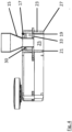
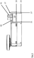
- Fig. 7 and 8 In the embodiment of a suction foot 13 according to the invention shown, the connection element 31 and the flushing fluid openings 33 are connected to one another via a flushing fluid line 35.
- a first end of the flushing fluid line 35 is connected to the connection element 31, while its second end is connected to the flushing fluid opening 33.
- the interior 29 of the suction foot base 17 is not used directly for distributing the flushing fluid, as is the case in the first embodiment.
- the suction foot base 17 it is not necessary for the suction foot base 17 to be designed as a closed hollow body. Otherwise, the basic functioning of the second embodiment is no different from the first, and the advantages already mentioned in connection with the first embodiment are achieved with the second embodiment.
Landscapes
- Cleaning In General (AREA)
- Nozzles For Electric Vacuum Cleaners (AREA)
- Cleaning By Liquid Or Steam (AREA)
Description
- Die vorliegende Erfindung betrifft einen Saugfuß für eine Bodenreinigungsmaschine, mit einer Saugfußbasis, die eine obere Wand aufweist, wobei sich eine Vorderwand und eine Rückwand von der oberen Wand erstrecken, wobei zwischen der Vorderwand und der Rückwand ein Absaugkanal gebildet ist und wobei die Rückwand eine Auflagekante zur Auflage auf einer zu reinigenden Bodenfläche aufweist, mit einem Absauganschluss, der mit dem Absaugkanal verbunden ist, sich vorzugsweise durch die obere Wand erstreckt und mit einer Absaugeinrichtung der Bodenreinigungsmaschine verbunden werden kann. Zudem betrifft die vorliegende Erfindung eine Bodenreinigungsmaschine mit einem solchen Saugfuß, sowie ein Verfahren zum Betrieb einer Bodenreinigungsmaschine.
- Bei aus dem Stand der Technik bekannten Bodenreinigungsmaschinen und insbesondere Scheuersaugmaschinen dient ein sogenannter Saugfuß dazu, eine auf einer zu reinigenden Bodenfläche vorhandene Flüssigkeit, die zuvor von einer Reinigungseinrichtung der Bodenreinigungsmaschine aufgebracht wurde und die Schmutz enthalten kann, von der Bodenfläche zu entfernen. Dieses geschieht durch Unterdruck, der durch eine dafür vorgesehene Absaugeinrichtung der Bodenreinigungsmaschine bereitgestellt und mit dem der Saugfuß, insbesondere dessen Absaugkanal, beaufschlagt wird.
- Während des Betriebs sammelt sich Schmutz insbesondere im Absaugkanal des Saugfußes an, und der Saugfuß muss in regelmäßigen Abständen gereinigt werden. Diese Reinigung des Saugfußes ist zeitaufwendig und häufig unbequem auszuführen.
- Aus der
DE 10 2013 204 400 A1 ist eine Schmutzaufnahmeeinrichtung für eine Bodenreinigungsmaschine bekannt, bei der Wasser in einer Verbindungsleitung in einen Luftstrom zugeführt wird, der von dem Absauganschluss der Aufnahmeeinrichtung zu einem Schmutzbehälter verläuft, wobei die Verbindungsleitung an dem Absauganschluss der angeschlossen ist. - Daher ist es die Aufgabe der vorliegenden Erfindung, einen Saugfuß bereitzustellen, der sich in einfacher Weise reinigen lässt.
- Diese Aufgabe wird durch einen Saugfuß gemäß Anspruch 1 gelöst. Der erfindungsgemäße Saugfuß weist eine Spüleinrichtung zum Zuführen von Spülfluid in den Absaugkanal auf, wobei die Spüleinrichtung ein Anschlusselement zum Verbinden mit einer Zuleitung für das Spülfluid aufweist und wobei das Anschlusselement an der Saugfußbasis angebracht und zum Zuführen von Spülfluid mit dem Absaugkanal verbunden ist.
- Mit zunehmender Betriebsdauer und wiederholtem Abschalten der Bodenreinigungsmaschine haften zunehmend Schmutzpartikel am Saugfuß und insbesondere an der den Absaugkanal begrenzenden Rückwand und können dort zu einer festen Schmutzschicht trocknen. Der erfindungsgemäße Saugfuß kann mittels der Spüleinrichtung in besonders einfacher Weise gereinigt werden, indem ein Spülfluid, beispielsweise Reinigungsflüssigkeit aus dem Reinigungsflüssigkeitstank der Bodenreinigungsmaschine, dem Anschlusselement des Saugfußes zugeführt und so in den Absaugkanal eingeleitet wird. Dieses Spülfluid kann dann wieder durch Absaugen mit Hilfe der an der Bodenreinigungsmaschine vorhandenen Absaugeinrichtung abgesaugt werden, sodass insbesondere der Absaugkanal in einfacher Weise gespült werden kann. Ein solcher Spülschritt kann einfach und in Zeitabständen erfolgen, die kürzer sind als die, die zwischen sonstigen Reinigungsvorgängen liegen, da dies mit einem sehr viel geringeren Aufwand verbunden ist. Dadurch können die anhaftenden Schmutzpartikel wenigstens teilweise entfernt werden, bevor diese am Saugfuß zu einer Schmutzschicht festtrocknen.
- Bei einer bevorzugten Ausführungsform kann die Vorderwand des Absaugkanals derart bemessen sein, dass sie sich nicht oder nicht über ihre gesamte Länge bis zu der zu reinigenden Bodenfläche erstreckt. Dadurch ist das Absaugen von Flüssigkeit bzw. Schmutzflüssigkeit von der zu reinigenden Bodenfläche vereinfacht. Weiterhin kann das Anschlusselement als Schlauchkupplung ausgebildet sein, sodass das Verbinden mit einer Zuleitung für das Spülfluid vereinfacht ist.
- Eine bevorzugte Ausführungsform des Saugfußes weist eine gekrümmte Saugfußbasis auf, deren Enden sich in Fahrtrichtung der Bodenreinigungsmaschine gesehen vor dem Absauganschluss befinden. Die Krümmung der Rückwand kann ferner insbesondere abschnittsweise geringer als die Krümmung der Vorderwand sein.
- Bei einer anderen bevorzugten Ausführungsform weist die Spüleinrichtung eine mit dem Anschlusselement verbundene Spülfluidöffnung auf, durch die das Spülfluid in den Absaugkanal eintreten kann und die von dem Absauganschluss beabstandet ist. Mit zunehmendem Abstand zwischen der Spülfluidöffnung und dem Absauganschluss kann ein längerer Abschnitt des Absaugkanals zuverlässig gespült werden. Bei dieser Ausführungsform ist die Reinigungswirkung durch das Spülfluid verbessert.
- Bei einer weiteren bevorzugten Ausführungsform erstrecken sich die Saugfußbasis, die Vorderwand und die Rückwand zwischen einem ersten Ende und einem zweiten Ende, und der Absauganschluss ist insbesondere mittig zwischen dem ersten und zweiten Ende angeordnet. Schließlich ist in dieser Ausführungsform die Spülfluidöffnung an dem ersten Ende angeordnet. Bei dieser Ausführungsform wird der gesamte Abschnitt zwischen dem ersten Ende und dem Absauganschluss zuverlässig gespült, wenn ein Spülfluid eingeleitet wird. Hier ist auch denkbar, dass eine weitere ebenfalls mit dem Anschlusselement verbundene Spülfluidöffnung an dem zweiten Ende angeordnet ist, sodass auch der Abschnitt zwischen dem zweiten Ende und dem Absauganschluss gespült wird.
- Eine andere bevorzugte Ausführungsform weist mehrere Spülfluidöffnungen auf, die mit dem Anschlusselement verbunden sind und durch die das Spülfluid in den Absaugkanal eintreten kann, wobei die Spülfluidöffnungen entlang der Rückwand angeordnet und zueinander beabstandet sind. Die Spülfluidöffnungen können zueinander regelmäßig beabstandet sein. Bei dieser Ausführungsform wird die Reinigungswirkung weiter verbessert.
- Bei einer weiteren bevorzugten Ausführungsform ist das Anschlusselement an der oberen, den Absaugkanal begrenzenden Wand angeordnet. Das Anschlusselement kann sich in Richtung der zu reinigenden Bodenfläche öffnen, wenn der Saugfuß an einer Bodenreinigungsmaschine angeordnet ist. Hier ergibt sich ein besonders einfacher Aufbau.
- Bei einer anderen bevorzugten Ausführungsform ist die Saugfußbasis als Hohlkörper mit einem Innenraum ausgebildet, wobei der zu dem Absaugkanal weisende Wandungsabschnitt des Hohlkörpers durch die obere Wand gebildet wird und wobei die Spülfluidöffnung(en) in der oberen Wand angeordnet ist/sind. Bei dieser Ausführungsform ist es nicht erforderlich, Leitungen oder dgl. in der Saugfußbasis vorzusehen, um die Spülfluidöffnungen mit dem Anschlusselement zu verbinden. Vielmehr bildet der Innenraum die Verbindung, und vorzugsweise ist das Anschlusselement derart an der Saugfußbasis angebracht, dass das Spülfluid durch das Anschlusselement in den Innenraum der Saugfußbasis einströmen kann. In weiter bevorzugter Weise erstreckt sich dann der Absauganschluss durch die obere Wand und den Innenraum hindurch.
- Bei einer weiteren bevorzugten Ausführungsform weist die Spüleinrichtung eine oder mehrere Spülfluidleitungen auf, deren erste Enden mit dem Anschlusselement verbunden sind und deren zweite Enden mit der oder den Spülfluidöffnungen verbunden ist. Bei dieser Ausführungsform ist es nicht erforderlich, die Saugfußbasis als Hohlkörper auszubilden.
- Die eingangs genannte Aufgabe wird ferner durch eine Bodenreinigungsmaschine mit dem erfindungsgemäßen Saugfuß gelöst. Die Bodenreinigungsmaschine weist ein Fahrwerk zum Bewegen der Bodenreinigungsmaschine über eine zu reinigende Bodenfläche, eine an dem Fahrwerk angebrachte Reinigungseinrichtung zum Aufbringen von Reinigungsflüssigkeit auf die zu reinigende Bodenfläche, einen Schmutzflüssigkeitstank, eine Absaugeinrichtung zum Absaugen von Schmutzflüssigkeit in den Schmutzflüssigkeitstank und einen der zuvor beschriebenen Saugfüße auf. Der Saugfuß ist in Fahrtrichtung hinter der Reinigungseinrichtung angeordnet, und der Absauganschluss ist mit der Absaugeinrichtung verbunden. Mit der erfindungsgemäßen Bodenreinigungsmaschine werden die bereits im Zusammenhang mit dem Saugfuß erläuterten Vorteile erreicht.
- Vorzugsweise weist die Bodenreinigungseinrichtung eine Aushebeeinrichtung auf, welche zum Abstützen des Saugfuß ausgestaltet ist. Die Aushebeeinrichtung kann den Saugfuß umkehrbar aus einem Ruhezustand, in dem die Auflagekante von der zu reinigenden Bodenfläche abgehoben ist, in einen Betriebszustand überführen, in dem die Auflagekante auf der zu reinigenden Bodenfläche aufliegt.
- Vorzugsweise ist bei der Bodenreinigungsmaschine ein Reinigungsflüssigkeitstank vorgesehen, mit dem das Anschlusselement verbunden ist. Die Reinigungsflüssigkeit kann das Spülfluid bilden. Der Reinigungsflüssigkeitstank kann als Reservoir für das Spülfluid dienen. So ist das Zuführen des Spülfluids in den Absaugkanal vereinfacht. In einer alternativen Ausführungsform kann das Anschlusselement auch derart ausgestaltet sein, dass es mit einem Hauswasseranschluss verbunden werden kann, sodass Hauswasser als Spülfluid verwendet werden kann.
- Schließlich wird die obige Aufgabe auch durch ein Verfahren zum Betrieb einer der vorgenannten Bodenreinigungsmaschinen gelöst, wobei das Verfahren die folgenden Schritte aufweist:
- Zuführen von Spülfluid aus einem Reservoir für Spülfluid durch das Anschlusselement in den Absaugkanal und
- Betreiben der Absaugeinrichtung zum Absaugen des Spülfluids aus dem Absaugkanal.
- Vorzugsweise ist bei dem vorgenannten Verfahren das Reservoir durch den Reinigungsflüssigkeitstank gebildet, und der Reinigungsflüssigkeitstank wird mit dem Anschlusselement verbunden, sodass Reinigungsflüssigkeit dem Anschlusselement als Spülfluid zum Spülen bzw. Reinigen zugeführt wird. So kann das Zuführen des Spülfluids in den Absaugkanal vereinfacht sein, insbesondere während des Betriebs der Bodenreinigungsmaschine.
- Alternativ wird während des ersten Schritts das Anschlusselement mit einem Hauswasseranschluss verbunden. So kann ein Bediener den Saugfuß bedarfsweise oder nach einem Wartungsplan reinigen.
- Schließlich ist es auch möglich, dass das Reservoir durch den Reinigungsflüssigkeitstank gebildet ist und der Reinigungsflüssigkeitstank mit dem Anschlusselement verbunden ist, wobei während des normalen Betriebs der Bodenreinigungsmaschine Reinigungsflüssigkeit in regelmäßigen Zeitabständen durch das Anschlusselement in der Absaugkanal zugeführt wird und dieser somit während des normalen Betriebs regelmäßig gereinigt wird.
- Im Folgenden wird die vorliegende Erfindung anhand einer lediglich bevorzugte Ausführungsbeispiele zeigenden Zeichnung beschrieben, wobei
- Fig. 1
- eine Seitenansicht einer Bodenreinigungsmaschine mit einem Saugfuß ist,
- Fig. 2
- eine perspektivische Ansicht eines ersten Ausführungsbeispiels eines erfindungsgemäßen Saugfußes ist,
- Fig. 3
- ein Schnitt durch den Saugfuß aus
Fig. 2 in der Nähe eines Endes ist, - Fig. 4
- ein Schnitt entlang der Mitte des Saugfußes aus
Fig. 2 ist, - Fig. 5
- einen Schnitt durch den Saugfuß aus
Fig. 2 im Bereich des Anschlusselements ist - Fig. 6
- eine perspektivische Darstellung der Strömung im Ausführungsbeispiel des erfindungsgemäßen Saugfußes ist,
- Fig. 7
- ein Schnitt durch ein zweites Ausführungsbeispiel eines erfindungsgemäßen Saugfußes in der Nähe eines Endes ist und
- Fig. 8
- ein Schnitt durch den Saugfuß aus
Fig. 7 im Bereich des Anschlusselements ist. -
Fig. 1 zeigt eine Seitenansicht einer Bodenreinigungsmaschine 1 mit einem Ausführungsbeispiel eines erfindungsgemäßen Saugfußes. Die Bodenreinigungsmaschine 1 weist ein Räder 3, 5 umfassendes Fahrwerk zum Bewegen der Bodenreinigungsmaschine 1 über eine zu reinigende Bodenfläche 7, eine an dem Fahrwerk angebrachte Reinigungseinrichtung 9 zum Aufbringen von Reinigungsflüssigkeit auf die zu reinigende Bodenfläche 7, einen Schmutzflüssigkeitstank 11, eine Absaugeinrichtung (nicht gezeigt) zum Absaugen von Schmutzflüssigkeit in den Schmutzflüssigkeitstank 11 und einen Saugfuß 13 entsprechend dem im Folgenden beschriebenen Ausführungsbeispiel auf. Der Saugfuß 13 ist in Fahrtrichtung F der Bodenreinigungsmaschine 1 hinter der Reinigungseinrichtung 9 angeordnet, und ein Absauganschluss 15 des Saugfußes 13 ist mit der Absaugeinrichtung verbunden. - Wie die
Fig. 2 bis 5 zeigen, hat das Ausführungsbeispiel eines Saugfußes 13 eine Saugfußbasis 17, an der eine obere Wand 19 ausgebildet ist, wobei sich eine Vorderwand 21 und eine Rückwand 23 von der oberen Wand 19 erstrecken, sodass zwischen der Vorderwand 21 und der Rückwand 23 ein Absaugkanal 25 gebildet ist, der nach oben durch die obere Wand 19 begrenzt ist. Außerdem weist die Rückwand 23 eine Auflagekante 27 zur Auflage auf die zu reinigenden Bodenfläche 7 auf. - Wie insbesondere
Fig. 4 zeigt, ist der Absauganschluss 15 in der Saugfußbasis 17 vorgesehen und erstreckt sich durch die obere Wand 19. Im Betrieb ist er mit einer Absaugeinrichtung der Bodenreinigungsmaschine 1 verbunden. AusFig. 2 ist dabei zu erkennen, dass der Absauganschluss 15 mittig zwischen dem ersten und zweiten Ende des Saugfußes 13 angeordnet ist, zwischen denen sich die Vorder- und die Rückwand 21, 23 erstrecken. - Wie weiter aus den
Fig. 2 bis 5 zu erkennen ist, ist die Saugfußbasis 17 als ein Hohlkörper ausgebildet, der einen geschlossenen Innenraum 29 definiert, dessen zu dem Absaugkanal 25 weisender Wandabschnitt von der oberen Wand 19 gebildet wird. Außerdem wird der Innenraum 29 durch eine Abdeckwand 30 und die Vorder- und die Rückwand 21, 23 begrenzt. Der Absauganschluss 15 erstreckt sich dabei durch den Innenraum 29 hindurch. Wie insbesondere inFig. 5 zu erkennen ist, ist an der Saugfußbasis 17 ein Anschlusselement 31 in der Abdeckwand 30 vorgesehen, das beispielsweise als Schlauchanschluss ausgebildet ist und über das ein Spülfluid in den Innenraum 29 eingeleitet werden kann. - In der oberen Wand 19 sind mehrere Spülfluidöffnungen 33 vorgesehen, die in diesem Ausführungsbeispiel in der Weise mit dem Anschlusselement 31 verbunden sind, dass sie ebenfalls von dem Innenraum 29 ausgehen, wobei in dem hier beschriebenen Ausführungsbeispiel die Spülfluidöffnungen 33 entlang der Rückwand 23 angeordnet und zueinander beabstandet sind. Es sind aber auch andere Anordnungen der Spülfluidöffnungen 33 denkbar. Insbesondere sind auch am ersten und zweiten Ende des Saugfußes 13 Spülfluidöffnungen 33 vorgesehen. Daher kann Spülfluid, das durch das Anschlusselement 31 in den Innenraum 29 geleitet worden ist, durch die Spülfluidöffnungen 33 in den Absaugkanal 25 eintreten. Damit bilden das Anschlusselement 31, der Innenraum 29 und die Spülfluidöffnungen 33 eine Spüleinrichtung für den Absaugkanal 25 des Saugfußes 13, deren Funktionsweise im Folgenden noch erläutert werden wird.
- Zum Reinigen des zuvor beschriebenen Ausführungsbeispiels eines erfindungsgemäßen Saugfußes 13 wird wie folgt vorgegangen:
Bei mit der Auflagekante 27 auf der Bodenfläche 7 aufliegendem Saugfuß 13 wird das Anschlusselement 31 mit einem Reservoir für Spülfluid, vorzugsweise dem Reinigungsflüssigkeitstank der Bodenreinigungsmaschine 1, verbunden, und Reinigungsflüssigkeit wird als Spülfluid dem Anschlusselement 31 zugeführt. Dieses gelangt von dort in den Innenraum 29 der Saugfußbasis 17 und weiter durch die Spülfluidöffnungen 33 in den Absaugkanal 25. Parallel wird auch die Absaugeinrichtung der Bodenreinigungsmaschine 1 betrieben, sodass das Spülfluid in Form der Reinigungsflüssigkeit durch den Absauganschluss 15 aus dem Absaugkanal 25 abgezogen wird, wobei in dem Absaugkanal 25 vorhandener Schmutz mitgerissen wird. Alternativ ist es auch möglich, dass als Spülfluid Wasser aus einem Hauswasseranschluss verwendet wird, wobei der Hauswasseranschluss über einen Schlauch mit dem Anschlusselement 31 verbunden wird, sodass das Hauswasser dann in den Absaugkanal 25 gelangt. - Schließlich ist es auch möglich, dass der Reinigungsflüssigkeitstank dauerhaft mit dem Anschlusselement verbunden ist, wobei Reinigungsflüssigkeit in regelmäßigen Zeitabständen durch das Anschlusselement 31 in der Absaugkanal 25 zugeführt wird. Damit kann der Saugfuß 13 während des normalen Betriebs regelmäßig gereinigt werden.
- Da die Spülfluidöffnungen 33 in dem Ausführungsbeispiel über die gesamte Breite des Saugfußes 13 und insbesondere auch an den Enden angeordnet sind, strömt Reinigungsflüssigkeit durch den gesamten Absaugkanal 25, wie dies schematisch in
Fig. 6 dargestellt ist, was zu einer besonders guten Reinigungswirkung führt. - Damit erlaubt der erfindungsgemäße Saugfuß 13 mit der Spüleinrichtung in Form des Anschlusselements 31, das mit den Spülfluidöffnungen 33 verbunden ist, auf einfache Weise eine effiziente Reinigung des Absaugkanals 25 des Saugfußes 13.
- In dem zuvor beschriebenen Ausführungsbeispiel ist das Anschlusselement 31 über den geschlossenen Innenraum 29 mit den Spülfluidöffnungen 33 verbunden. Bei dem zweiten, in den
Fig. 7 und8 gezeigten Ausführungsbeispiel eines erfindungsgemäßen Saugfußes 13 sind das Anschlusselement 31 und die Spülfluidöffnungen 33 über eine Spülfluidleitung 35 miteinander verbunden. Insbesondere ist ein erstes Ende der Spülfluidleitung 35 mit dem Anschlusselement 31 verbunden, während deren zweites Ende mit der Spülfluidöffnung 33 verbunden ist. Demnach wird bei diesem zweiten Ausführungsbeispiel der Innenraum 29 der Saugfußbasis 17 nicht unmittelbar zur Verteilung des Spülfluids genutzt, wie dies bei dem ersten Ausführungsbeispiel der Fall ist. Außerdem ist es bei diesem Ausführungsbeispiel nicht erforderlich, dass die Saugfußbasis 17 als geschlossener Hohlkörper ausgebildet ist. Ansonsten unterscheidet sich das zweite Ausführungsbeispiel in der grundsätzlichen Funktionsweise nicht von dem Ersten, und es werden mit dem zweiten Ausführungsbeispiel die schon im Zusammenhang mit dem ersten Ausführungsbeispiel genannten Vorteile erzielt. -
- 1
- Bodenreinigungsmaschine
- 3, 5
- Räder
- 7
- Bodenfläche
- 9
- Reinigungseinrichtung
- 11
- Schmutzflüssigkeitstank
- 13
- Saugfuß
- 15
- Absauganschluss
- 17
- Saugfußbasis
- 19
- obere Wand
- 21
- Vorderwand
- 23
- Rückwand
- 25
- Absaugkanal
- 27
- Auflagekante
- 29
- Innenraum
- 30
- Abdeckwand
- 31
- Anschlusselement
- 33
- Spülfluidöffnungen
- 35
- Spülfluidleitung
Claims (14)
- Saugfuß für eine Bodenreinigungsmaschine (1) miteiner Saugfußbasis (17), die eine obere Wand (19) aufweist, wobei sich eine Vorderwand (21) und eine Rückwand (23) von der oberen Wand (19) erstrecken, wobei zwischen der Vorderwand (21) und der Rückwand (23) ein Absaugkanal (25) gebildet ist und wobei die Rückwand (23) eine Auflagekante (27) zur Auflage auf einer zu reinigenden Bodenfläche (7) aufweist,mit einem Absauganschluss (15), der mit dem Absaugkanal (25) verbunden ist und mit einer Absaugeinrichtung der Bodenreinigungsmaschine (1) verbunden werden kann,gekennzeichnet durch eine Spüleinrichtung zum Zuführen von Spülfluid in den Absaugkanal (25), wobei die Spüleinrichtung ein Anschlusselement (31) zum Verbinden mit einer Zuleitung für das Spülfluid aufweist, wobei das Anschlusselement (31) an der Saugfußbasis (17) angebracht und zum Zuführen von Spülfluid mit dem Absaugkanal (25) verbunden ist.
- Saugfuß nach Anspruch 1, wobei die Spüleinrichtung eine mit dem Anschlusselement verbundene Spülfluidöffnung (31) aufweist, durch die das Spülfluid in den Absaugkanal eintreten kann und die von dem Absauganschluss beabstandet ist.
- Saugfuß nach Anspruch 2, wobei sich die Saugfußbasis (17), die Vorderwand (21) und die Rückwand (23) zwischen einem ersten Ende und einem zweiten Ende erstrecken und der Absauganschluss (15) insbesondere mittig zwischen dem ersten und zweiten Ende angeordnet ist und wobei die Spülfluidöffnungen (33) an dem ersten und dem zweiten Ende angeordnet sind.
- Saugfuß nach Anspruch 1 oder 2, wobei mehrere Spülfluidöffnungen (33) vorgesehen sind, die mit dem Anschlusselement (31) verbunden sind und durch die das Spülfluid in den Absaugkanal (25) eintreten kann, wobei die Spülfluidöffnungen (33) entlang der Rückwand (23) angeordnet und zueinander beabstandet sind.
- Saugfuß nach einem der vorhergehenden Ansprüche, wobei das Anschlusselement (31) an der oberen Wand (19) angeordnet ist.
- Saugfuß nach einem der vorhergehenden Ansprüche, wobei die Saugfußbasis (17) als Hohlkörper mit einem Innenraum (29) ausgebildet ist,wobei der zu dem Absaugkanal (25) weisende Wandungsabschnitt des Hohlkörpers durch die obere Wand (19) gebildet wird undwobei die Spülfluidöffnung(en) (33) in der oberen Wand (19) angeordnet ist/sind.
- Saugfuß nach Anspruch 6, wobei das Anschlusselement (31) derart an der Saugfußbasis (17) angebracht ist, dass Spülfluid durch das Anschlusselement (31) in den Innenraum (29) der Saugfußbasis (17) einströmen kann.
- Saugfuß nach Anspruch 6 oder 7, wobei sich der Absauganschluss (15) durch die obere Wand (19) und den Innenraum (29) hindurch erstreckt.
- Saugfuß nach einem der Ansprüche 2 bis 6 oder 8, wobei die Spüleinrichtung eine oder mehrere Spülfluidleitungen (35) aufweist, deren erste Enden mit dem Anschlusselement (31) verbunden sind und deren zweite Enden mit der oder den Spülfluidöffnungen (33) verbunden ist.
- Bodenreinigungsmaschine (1) mit einem Fahrwerk zum Bewegen der Bodenreinigungsmaschine über eine zu reinigende Bodenfläche (7), mit einer an dem Fahrwerk angebrachten Reinigungseinrichtung (9) zum Aufbringen von Reinigungsflüssigkeit auf die zu reinigende Bodenfläche (7), mit einem Schmutzflüssigkeitstank (11), mit einer Absaugeinrichtung zum Absaugen von Schmutzflüssigkeit in den Schmutzflüssigkeitstank (11) und mit einem Saugfuß (13) nach einem der vorhergehenden Ansprüche,wobei der Saugfuß (13) in Fahrtrichtung hinter der Reinigungseinrichtung (9) angeordnet ist undwobei der Absauganschluss (15) mit der Absaugeinrichtung verbunden ist.
- Bodenreinigungsmaschine nach Anspruch 10, wobei ein Reinigungsflüssigkeitstank vorgesehen ist und das Anschlusselement (31) mit dem Reinigungsflüssigkeitstank verbunden ist.
- Verfahren zum Betrieb einer Bodenreinigungsmaschine nach Anspruch 10 oder 11, mit den folgenden Schritten:Zuführen von Spülfluid aus einem Reservoir für Spülfluid durch das Anschlusselement (31) in den Absaugkanal (25) undBetreiben der Absaugeinrichtung zum Absaugen des Spülfluids aus dem Absaugkanal (25).
- Verfahren nach Anspruch 12, wobei das Reservoir durch den Reinigungsflüssigkeitstank gebildet ist und der Reinigungsflüssigkeitstank mit dem Anschlusselement (31) verbunden wird, sodass Reinigungsflüssigkeit als Spülfluid dem Anschlusselement (31) zugeführt wird.
- Verfahren nach Anspruch 12, wobei das Reservoir durch den Reinigungsflüssigkeitstank gebildet ist und der Reinigungsflüssigkeitstank mit dem Anschlusselement (31) verbunden ist und
wobei Reinigungsflüssigkeit in regelmäßigen Zeitabständen durch das Anschlusselement (31) in der Absaugkanal (25) zugeführt wird.
Applications Claiming Priority (1)
| Application Number | Priority Date | Filing Date | Title |
|---|---|---|---|
| DE102017110774.6A DE102017110774A1 (de) | 2017-05-17 | 2017-05-17 | Saugfuß für eine Bodenreinigungsmaschine |
Publications (2)
| Publication Number | Publication Date |
|---|---|
| EP3415068A1 EP3415068A1 (de) | 2018-12-19 |
| EP3415068B1 true EP3415068B1 (de) | 2024-10-30 |
Family
ID=62196468
Family Applications (1)
| Application Number | Title | Priority Date | Filing Date |
|---|---|---|---|
| EP18172885.8A Active EP3415068B1 (de) | 2017-05-17 | 2018-05-17 | Saugfuss für eine bodenreinigungsmaschine |
Country Status (5)
| Country | Link |
|---|---|
| EP (1) | EP3415068B1 (de) |
| JP (1) | JP7534066B2 (de) |
| KR (1) | KR102573249B1 (de) |
| CN (1) | CN108937753A (de) |
| DE (1) | DE102017110774A1 (de) |
Families Citing this family (2)
| Publication number | Priority date | Publication date | Assignee | Title |
|---|---|---|---|---|
| DE102022111607A1 (de) * | 2022-05-10 | 2023-11-16 | Hako Gmbh | Saugfußanordnung für eine Bodenreinigungsmaschine |
| KR102543823B1 (ko) | 2023-03-20 | 2023-06-16 | 클레온(주) | 탑승식 노면세척기의 스퀴지 구조 |
Family Cites Families (17)
| Publication number | Priority date | Publication date | Assignee | Title |
|---|---|---|---|---|
| GB1483261A (en) | 1974-10-09 | 1977-08-17 | Melford Eng Ltd | Suction cleaning apparatus |
| US4596061A (en) | 1985-01-22 | 1986-06-24 | Henning John J | Liquid-vacuum washer for hard surfaces |
| JP2591730Y2 (ja) * | 1991-07-08 | 1999-03-10 | ユシロ化学工業株式会社 | 床面清掃車 |
| JPH1034095A (ja) * | 1996-07-22 | 1998-02-10 | Tanikoo Fukushima Hanbai Kk | 洗浄器具、及びこれに用いられる水循環装置 |
| DK0917437T3 (da) * | 1997-03-06 | 2004-02-16 | Vorwerk Co Interholding | Gulvrengøringsindretning til rengøring ved hjælp af fugtighed og sugning |
| DE29914329U1 (de) * | 1999-08-16 | 2000-12-28 | FAUN Viatec GmbH, 04668 Grimma | Saugdüse |
| JP3568837B2 (ja) * | 1999-09-30 | 2004-09-22 | アマノ株式会社 | 床面洗浄清掃機 |
| JP3871888B2 (ja) * | 2001-02-14 | 2007-01-24 | アマノ株式会社 | 床面洗浄機用スキージ |
| JP4141827B2 (ja) | 2002-12-27 | 2008-08-27 | アマノ株式会社 | カーペットクリーナー |
| US20050125935A1 (en) * | 2003-12-16 | 2005-06-16 | Leonatti John A. | Cleaning machine for cleaning a surface |
| JP4363995B2 (ja) * | 2004-01-23 | 2009-11-11 | 株式会社東芝 | 吸込口体および掃除装置 |
| JP4535900B2 (ja) * | 2005-02-14 | 2010-09-01 | 花王株式会社 | 湿式電気掃除機 |
| DE102005048092B4 (de) * | 2005-09-30 | 2007-10-18 | Alfred Kärcher Gmbh & Co. Kg | Flächenreinigungskopf |
| DE102007034702A1 (de) * | 2007-07-18 | 2009-01-22 | Alfred Kärcher Gmbh & Co. Kg | Schmutzaufnahmevorrichtung für eine Bodenreinigungsmaschine sowie Bodenreinigungsmaschine mit einer derartigen Schmutzaufnahmevorrichtung |
| CN104023611B (zh) * | 2011-11-02 | 2016-11-23 | 阿尔弗雷德·凯驰两合公司 | 用手引导的地板清洁机 |
| US20130180550A1 (en) * | 2012-01-12 | 2013-07-18 | Willie Dee Kent | Cleaning heads and methods of use |
| DE102013204400B4 (de) * | 2013-03-13 | 2015-02-05 | Hako Gmbh | Bodenreinigungsmaschine mit einer Saugeinheit mit einem Flüssigkeitszuführungssystem |
-
2017
- 2017-05-17 DE DE102017110774.6A patent/DE102017110774A1/de active Pending
-
2018
- 2018-05-16 CN CN201810468286.4A patent/CN108937753A/zh active Pending
- 2018-05-16 JP JP2018094699A patent/JP7534066B2/ja active Active
- 2018-05-17 KR KR1020180056740A patent/KR102573249B1/ko active Active
- 2018-05-17 EP EP18172885.8A patent/EP3415068B1/de active Active
Also Published As
| Publication number | Publication date |
|---|---|
| KR20180126404A (ko) | 2018-11-27 |
| JP7534066B2 (ja) | 2024-08-14 |
| DE102017110774A1 (de) | 2018-11-22 |
| EP3415068A1 (de) | 2018-12-19 |
| CN108937753A (zh) | 2018-12-07 |
| JP2018192261A (ja) | 2018-12-06 |
| KR102573249B1 (ko) | 2023-08-30 |
Similar Documents
| Publication | Publication Date | Title |
|---|---|---|
| EP3730019B1 (de) | Bodenreinigungsmaschine | |
| DE102018111499B3 (de) | Bodenreinigungsmaschine mit kombinierter Saug-Ablass-Leitung | |
| DE60113122T2 (de) | Roboter zur vakuumreinigung von schwimmbädern unter druckzufuhr und vefahren | |
| EP3968831A1 (de) | Reinigungsvorrichtung für die reinigung einer rotierbaren bürstenwalze eines reinigungsgerätes und reinigungssystem | |
| WO2019048449A1 (de) | Selbstfahrendes und selbstlenkendes bodenreinigungsgerät, bodenreinigungssystem und verfahren zum reinigen einer bodenfläche | |
| EP2170148A1 (de) | Schmutzaufnahmevorrichtung für eine bodenreinigungsmaschine sowie bodenreinigungsmaschine mit einer derartigen schmutzaufnahmevorrichtung | |
| DE3128928C2 (de) | Vorrichtung zum Reinigen von farbführenden Walzen eines Walzenfarbwerkes für Druckmaschinen | |
| DE19705006A1 (de) | Vorrichtung zum Zuführen und Absaugen von Farbe in Druckmaschinen | |
| EP3415068A1 (de) | Saugfuss für eine bodenreinigungsmaschine | |
| DE60014488T2 (de) | Siebdruckvorrichtung mit einer Reinigungseinheit, die innerhalb eines Stencils ersetzbar ist | |
| EP0415283B1 (de) | Vorrichtung zum Begrenzen der Ausbreitung einer gegen einen textilen Stoff gespritzten Behandlungsflüssigkeit | |
| DE10221349A1 (de) | Bodenreinigungsmaschine | |
| EP2949253B1 (de) | SAUGFUß FÜR EINE BODENREINIGUNGSMASCHINE | |
| DE60306362T2 (de) | Düsen für eine reinigungsanlage einer druckmaschine | |
| DE19516456A1 (de) | Vorrichtung zur Reinigung einer Rakelvorrichtung für ein Spülfarbwerk einer Rotationsdruckmaschine | |
| DE2724888B2 (de) | Vorrichtung zur Reinigung von Tuscheschreiberspitzen | |
| DE2934268C2 (de) | Waschvorrichtung für einen Gummituchzylinder einer Druckmaschine | |
| DE69909296T2 (de) | Verfahren zum trennen von körnchen aus einer reinigungsflüssigkeitsmischung für gegenstände, die in einer waschmaschine angeordnet sind, und waschmaschine mit einem körnchenseparator | |
| DE4141711C2 (de) | Fahrbare Naßreinigungsmaschine | |
| EP2387933A2 (de) | Verfahren zum Reinigen einer Bodenfläche und Bodenreinigungsgerät zur Durchführung des Verfahrens | |
| DE102007022096A1 (de) | Vorrichtung zum Behandeln, Bearbeiten und/oder Reinigen von Oberflächen | |
| DE102020118774A1 (de) | Bodenreinigungsvorrichtung für eine Bodenreinigungsmaschine sowie Bodenreinigungsmaschine | |
| EP2777465B1 (de) | Bodenreinigungsmaschine mit Handsaugschlauch | |
| DE3103720A1 (de) | Verfahren zum reinigen von gardinen o.dgl. und maschine zur durchfuehrung des verfahrens | |
| EP3378369A1 (de) | Saugfuss für eine bodenreinigungsmaschine |
Legal Events
| Date | Code | Title | Description |
|---|---|---|---|
| PUAI | Public reference made under article 153(3) epc to a published international application that has entered the european phase |
Free format text: ORIGINAL CODE: 0009012 |
|
| STAA | Information on the status of an ep patent application or granted ep patent |
Free format text: STATUS: THE APPLICATION HAS BEEN PUBLISHED |
|
| AK | Designated contracting states |
Kind code of ref document: A1 Designated state(s): AL AT BE BG CH CY CZ DE DK EE ES FI FR GB GR HR HU IE IS IT LI LT LU LV MC MK MT NL NO PL PT RO RS SE SI SK SM TR |
|
| AX | Request for extension of the european patent |
Extension state: BA ME |
|
| STAA | Information on the status of an ep patent application or granted ep patent |
Free format text: STATUS: REQUEST FOR EXAMINATION WAS MADE |
|
| 17P | Request for examination filed |
Effective date: 20190619 |
|
| RBV | Designated contracting states (corrected) |
Designated state(s): AL AT BE BG CH CY CZ DE DK EE ES FI FR GB GR HR HU IE IS IT LI LT LU LV MC MK MT NL NO PL PT RO RS SE SI SK SM TR |
|
| STAA | Information on the status of an ep patent application or granted ep patent |
Free format text: STATUS: EXAMINATION IS IN PROGRESS |
|
| 17Q | First examination report despatched |
Effective date: 20221115 |
|
| GRAP | Despatch of communication of intention to grant a patent |
Free format text: ORIGINAL CODE: EPIDOSNIGR1 |
|
| STAA | Information on the status of an ep patent application or granted ep patent |
Free format text: STATUS: GRANT OF PATENT IS INTENDED |
|
| INTG | Intention to grant announced |
Effective date: 20240524 |
|
| GRAS | Grant fee paid |
Free format text: ORIGINAL CODE: EPIDOSNIGR3 |
|
| GRAA | (expected) grant |
Free format text: ORIGINAL CODE: 0009210 |
|
| STAA | Information on the status of an ep patent application or granted ep patent |
Free format text: STATUS: THE PATENT HAS BEEN GRANTED |
|
| AK | Designated contracting states |
Kind code of ref document: B1 Designated state(s): AL AT BE BG CH CY CZ DE DK EE ES FI FR GB GR HR HU IE IS IT LI LT LU LV MC MK MT NL NO PL PT RO RS SE SI SK SM TR |
|
| REG | Reference to a national code |
Ref country code: GB Ref legal event code: FG4D Free format text: NOT ENGLISH |
|
| REG | Reference to a national code |
Ref country code: CH Ref legal event code: EP |
|
| REG | Reference to a national code |
Ref country code: IE Ref legal event code: FG4D Free format text: LANGUAGE OF EP DOCUMENT: GERMAN |
|
| REG | Reference to a national code |
Ref country code: DE Ref legal event code: R096 Ref document number: 502018015269 Country of ref document: DE |
|
| REG | Reference to a national code |
Ref country code: LT Ref legal event code: MG9D |
|
| REG | Reference to a national code |
Ref country code: NL Ref legal event code: MP Effective date: 20241030 |
|
| PG25 | Lapsed in a contracting state [announced via postgrant information from national office to epo] |
Ref country code: IS Free format text: LAPSE BECAUSE OF FAILURE TO SUBMIT A TRANSLATION OF THE DESCRIPTION OR TO PAY THE FEE WITHIN THE PRESCRIBED TIME-LIMIT Effective date: 20250228 Ref country code: PT Free format text: LAPSE BECAUSE OF FAILURE TO SUBMIT A TRANSLATION OF THE DESCRIPTION OR TO PAY THE FEE WITHIN THE PRESCRIBED TIME-LIMIT Effective date: 20250228 Ref country code: HR Free format text: LAPSE BECAUSE OF FAILURE TO SUBMIT A TRANSLATION OF THE DESCRIPTION OR TO PAY THE FEE WITHIN THE PRESCRIBED TIME-LIMIT Effective date: 20241030 |
|
| PG25 | Lapsed in a contracting state [announced via postgrant information from national office to epo] |
Ref country code: FI Free format text: LAPSE BECAUSE OF FAILURE TO SUBMIT A TRANSLATION OF THE DESCRIPTION OR TO PAY THE FEE WITHIN THE PRESCRIBED TIME-LIMIT Effective date: 20241030 Ref country code: NL Free format text: LAPSE BECAUSE OF FAILURE TO SUBMIT A TRANSLATION OF THE DESCRIPTION OR TO PAY THE FEE WITHIN THE PRESCRIBED TIME-LIMIT Effective date: 20241030 |
|
| PG25 | Lapsed in a contracting state [announced via postgrant information from national office to epo] |
Ref country code: BG Free format text: LAPSE BECAUSE OF FAILURE TO SUBMIT A TRANSLATION OF THE DESCRIPTION OR TO PAY THE FEE WITHIN THE PRESCRIBED TIME-LIMIT Effective date: 20241030 |
|
| PG25 | Lapsed in a contracting state [announced via postgrant information from national office to epo] |
Ref country code: ES Free format text: LAPSE BECAUSE OF FAILURE TO SUBMIT A TRANSLATION OF THE DESCRIPTION OR TO PAY THE FEE WITHIN THE PRESCRIBED TIME-LIMIT Effective date: 20241030 |
|
| PG25 | Lapsed in a contracting state [announced via postgrant information from national office to epo] |
Ref country code: NO Free format text: LAPSE BECAUSE OF FAILURE TO SUBMIT A TRANSLATION OF THE DESCRIPTION OR TO PAY THE FEE WITHIN THE PRESCRIBED TIME-LIMIT Effective date: 20250130 |
|
| PG25 | Lapsed in a contracting state [announced via postgrant information from national office to epo] |
Ref country code: LV Free format text: LAPSE BECAUSE OF FAILURE TO SUBMIT A TRANSLATION OF THE DESCRIPTION OR TO PAY THE FEE WITHIN THE PRESCRIBED TIME-LIMIT Effective date: 20241030 Ref country code: GR Free format text: LAPSE BECAUSE OF FAILURE TO SUBMIT A TRANSLATION OF THE DESCRIPTION OR TO PAY THE FEE WITHIN THE PRESCRIBED TIME-LIMIT Effective date: 20250131 |
|
| PG25 | Lapsed in a contracting state [announced via postgrant information from national office to epo] |
Ref country code: PL Free format text: LAPSE BECAUSE OF FAILURE TO SUBMIT A TRANSLATION OF THE DESCRIPTION OR TO PAY THE FEE WITHIN THE PRESCRIBED TIME-LIMIT Effective date: 20241030 |
|
| PG25 | Lapsed in a contracting state [announced via postgrant information from national office to epo] |
Ref country code: RS Free format text: LAPSE BECAUSE OF FAILURE TO SUBMIT A TRANSLATION OF THE DESCRIPTION OR TO PAY THE FEE WITHIN THE PRESCRIBED TIME-LIMIT Effective date: 20250130 |
|
| PG25 | Lapsed in a contracting state [announced via postgrant information from national office to epo] |
Ref country code: SM Free format text: LAPSE BECAUSE OF FAILURE TO SUBMIT A TRANSLATION OF THE DESCRIPTION OR TO PAY THE FEE WITHIN THE PRESCRIBED TIME-LIMIT Effective date: 20241030 |
|
| PGFP | Annual fee paid to national office [announced via postgrant information from national office to epo] |
Ref country code: DE Payment date: 20250519 Year of fee payment: 8 |
|
| PG25 | Lapsed in a contracting state [announced via postgrant information from national office to epo] |
Ref country code: DK Free format text: LAPSE BECAUSE OF FAILURE TO SUBMIT A TRANSLATION OF THE DESCRIPTION OR TO PAY THE FEE WITHIN THE PRESCRIBED TIME-LIMIT Effective date: 20241030 |
|
| PGFP | Annual fee paid to national office [announced via postgrant information from national office to epo] |
Ref country code: IT Payment date: 20250530 Year of fee payment: 8 |
|
| PG25 | Lapsed in a contracting state [announced via postgrant information from national office to epo] |
Ref country code: EE Free format text: LAPSE BECAUSE OF FAILURE TO SUBMIT A TRANSLATION OF THE DESCRIPTION OR TO PAY THE FEE WITHIN THE PRESCRIBED TIME-LIMIT Effective date: 20241030 |
|
| PGFP | Annual fee paid to national office [announced via postgrant information from national office to epo] |
Ref country code: FR Payment date: 20250523 Year of fee payment: 8 |
|
| PG25 | Lapsed in a contracting state [announced via postgrant information from national office to epo] |
Ref country code: RO Free format text: LAPSE BECAUSE OF FAILURE TO SUBMIT A TRANSLATION OF THE DESCRIPTION OR TO PAY THE FEE WITHIN THE PRESCRIBED TIME-LIMIT Effective date: 20241030 |
|
| PGFP | Annual fee paid to national office [announced via postgrant information from national office to epo] |
Ref country code: AT Payment date: 20250519 Year of fee payment: 8 |
|
| PG25 | Lapsed in a contracting state [announced via postgrant information from national office to epo] |
Ref country code: SK Free format text: LAPSE BECAUSE OF FAILURE TO SUBMIT A TRANSLATION OF THE DESCRIPTION OR TO PAY THE FEE WITHIN THE PRESCRIBED TIME-LIMIT Effective date: 20241030 |
|
| PG25 | Lapsed in a contracting state [announced via postgrant information from national office to epo] |
Ref country code: CZ Free format text: LAPSE BECAUSE OF FAILURE TO SUBMIT A TRANSLATION OF THE DESCRIPTION OR TO PAY THE FEE WITHIN THE PRESCRIBED TIME-LIMIT Effective date: 20241030 |
|
| REG | Reference to a national code |
Ref country code: DE Ref legal event code: R097 Ref document number: 502018015269 Country of ref document: DE |
|
| PLBE | No opposition filed within time limit |
Free format text: ORIGINAL CODE: 0009261 |
|
| STAA | Information on the status of an ep patent application or granted ep patent |
Free format text: STATUS: NO OPPOSITION FILED WITHIN TIME LIMIT |
|
| PG25 | Lapsed in a contracting state [announced via postgrant information from national office to epo] |
Ref country code: SE Free format text: LAPSE BECAUSE OF FAILURE TO SUBMIT A TRANSLATION OF THE DESCRIPTION OR TO PAY THE FEE WITHIN THE PRESCRIBED TIME-LIMIT Effective date: 20241030 |
|
| 26N | No opposition filed |
Effective date: 20250731 |
|
| REG | Reference to a national code |
Ref country code: CH Ref legal event code: H13 Free format text: ST27 STATUS EVENT CODE: U-0-0-H10-H13 (AS PROVIDED BY THE NATIONAL OFFICE) Effective date: 20251223 |
|
| PG25 | Lapsed in a contracting state [announced via postgrant information from national office to epo] |
Ref country code: LU Free format text: LAPSE BECAUSE OF NON-PAYMENT OF DUE FEES Effective date: 20250517 |
|
| PG25 | Lapsed in a contracting state [announced via postgrant information from national office to epo] |
Ref country code: CH Free format text: LAPSE BECAUSE OF NON-PAYMENT OF DUE FEES Effective date: 20250531 |
|
| GBPC | Gb: european patent ceased through non-payment of renewal fee |
Effective date: 20250517 |
|
| REG | Reference to a national code |
Ref country code: BE Ref legal event code: MM Effective date: 20250531 |
|
| PG25 | Lapsed in a contracting state [announced via postgrant information from national office to epo] |
Ref country code: MC Free format text: LAPSE BECAUSE OF FAILURE TO SUBMIT A TRANSLATION OF THE DESCRIPTION OR TO PAY THE FEE WITHIN THE PRESCRIBED TIME-LIMIT Effective date: 20241030 |
|
| PG25 | Lapsed in a contracting state [announced via postgrant information from national office to epo] |
Ref country code: GB Free format text: LAPSE BECAUSE OF NON-PAYMENT OF DUE FEES Effective date: 20250517 |
|
| PG25 | Lapsed in a contracting state [announced via postgrant information from national office to epo] |
Ref country code: IE Free format text: LAPSE BECAUSE OF NON-PAYMENT OF DUE FEES Effective date: 20250517 |
|
| PG25 | Lapsed in a contracting state [announced via postgrant information from national office to epo] |
Ref country code: BE Free format text: LAPSE BECAUSE OF NON-PAYMENT OF DUE FEES Effective date: 20250531 |