EP3411320B1 - Spreizer zum heben eines intermodalen behälters - Google Patents
Spreizer zum heben eines intermodalen behälters Download PDFInfo
- Publication number
- EP3411320B1 EP3411320B1 EP16889565.4A EP16889565A EP3411320B1 EP 3411320 B1 EP3411320 B1 EP 3411320B1 EP 16889565 A EP16889565 A EP 16889565A EP 3411320 B1 EP3411320 B1 EP 3411320B1
- Authority
- EP
- European Patent Office
- Prior art keywords
- travelling
- spreader
- guide
- twist
- beams
- Prior art date
- Legal status (The legal status is an assumption and is not a legal conclusion. Google has not performed a legal analysis and makes no representation as to the accuracy of the status listed.)
- Active
Links
- 238000005266 casting Methods 0.000 claims description 51
- 239000000463 material Substances 0.000 claims description 38
- 229910000831 Steel Inorganic materials 0.000 claims description 19
- 239000010959 steel Substances 0.000 claims description 19
- 239000000725 suspension Substances 0.000 claims description 17
- 238000000034 method Methods 0.000 claims description 8
- 238000003466 welding Methods 0.000 claims description 7
- 238000000926 separation method Methods 0.000 claims description 6
- 230000004323 axial length Effects 0.000 claims description 3
- 230000000284 resting effect Effects 0.000 claims description 3
- 230000002787 reinforcement Effects 0.000 description 9
- 230000000903 blocking effect Effects 0.000 description 7
- 230000001965 increasing effect Effects 0.000 description 3
- 230000007423 decrease Effects 0.000 description 2
- 230000001939 inductive effect Effects 0.000 description 2
- 238000004519 manufacturing process Methods 0.000 description 2
- 230000013011 mating Effects 0.000 description 2
- 230000001154 acute effect Effects 0.000 description 1
- 230000015572 biosynthetic process Effects 0.000 description 1
- 239000000969 carrier Substances 0.000 description 1
- 230000003247 decreasing effect Effects 0.000 description 1
- 238000009826 distribution Methods 0.000 description 1
- 230000001747 exhibiting effect Effects 0.000 description 1
- 230000008520 organization Effects 0.000 description 1
- 229920003023 plastic Polymers 0.000 description 1
- 239000004033 plastic Substances 0.000 description 1
- 229920002635 polyurethane Polymers 0.000 description 1
- 239000004814 polyurethane Substances 0.000 description 1
- 238000003825 pressing Methods 0.000 description 1
- 239000013585 weight reducing agent Substances 0.000 description 1
Images


Classifications
-
- B—PERFORMING OPERATIONS; TRANSPORTING
- B66—HOISTING; LIFTING; HAULING
- B66C—CRANES; LOAD-ENGAGING ELEMENTS OR DEVICES FOR CRANES, CAPSTANS, WINCHES, OR TACKLES
- B66C1/00—Load-engaging elements or devices attached to lifting or lowering gear of cranes or adapted for connection therewith for transmitting lifting forces to articles or groups of articles
- B66C1/10—Load-engaging elements or devices attached to lifting or lowering gear of cranes or adapted for connection therewith for transmitting lifting forces to articles or groups of articles by mechanical means
- B66C1/101—Load-engaging elements or devices attached to lifting or lowering gear of cranes or adapted for connection therewith for transmitting lifting forces to articles or groups of articles by mechanical means for containers
-
- B—PERFORMING OPERATIONS; TRANSPORTING
- B66—HOISTING; LIFTING; HAULING
- B66C—CRANES; LOAD-ENGAGING ELEMENTS OR DEVICES FOR CRANES, CAPSTANS, WINCHES, OR TACKLES
- B66C1/00—Load-engaging elements or devices attached to lifting or lowering gear of cranes or adapted for connection therewith for transmitting lifting forces to articles or groups of articles
- B66C1/10—Load-engaging elements or devices attached to lifting or lowering gear of cranes or adapted for connection therewith for transmitting lifting forces to articles or groups of articles by mechanical means
- B66C1/62—Load-engaging elements or devices attached to lifting or lowering gear of cranes or adapted for connection therewith for transmitting lifting forces to articles or groups of articles by mechanical means comprising article-engaging members of a shape complementary to that of the articles to be handled
- B66C1/66—Load-engaging elements or devices attached to lifting or lowering gear of cranes or adapted for connection therewith for transmitting lifting forces to articles or groups of articles by mechanical means comprising article-engaging members of a shape complementary to that of the articles to be handled for engaging holes, recesses, or abutments on articles specially provided for facilitating handling thereof
- B66C1/663—Load-engaging elements or devices attached to lifting or lowering gear of cranes or adapted for connection therewith for transmitting lifting forces to articles or groups of articles by mechanical means comprising article-engaging members of a shape complementary to that of the articles to be handled for engaging holes, recesses, or abutments on articles specially provided for facilitating handling thereof for containers
-
- B—PERFORMING OPERATIONS; TRANSPORTING
- B66—HOISTING; LIFTING; HAULING
- B66C—CRANES; LOAD-ENGAGING ELEMENTS OR DEVICES FOR CRANES, CAPSTANS, WINCHES, OR TACKLES
- B66C1/00—Load-engaging elements or devices attached to lifting or lowering gear of cranes or adapted for connection therewith for transmitting lifting forces to articles or groups of articles
- B66C1/10—Load-engaging elements or devices attached to lifting or lowering gear of cranes or adapted for connection therewith for transmitting lifting forces to articles or groups of articles by mechanical means
- B66C1/62—Load-engaging elements or devices attached to lifting or lowering gear of cranes or adapted for connection therewith for transmitting lifting forces to articles or groups of articles by mechanical means comprising article-engaging members of a shape complementary to that of the articles to be handled
- B66C1/66—Load-engaging elements or devices attached to lifting or lowering gear of cranes or adapted for connection therewith for transmitting lifting forces to articles or groups of articles by mechanical means comprising article-engaging members of a shape complementary to that of the articles to be handled for engaging holes, recesses, or abutments on articles specially provided for facilitating handling thereof
-
- B—PERFORMING OPERATIONS; TRANSPORTING
- B66—HOISTING; LIFTING; HAULING
- B66C—CRANES; LOAD-ENGAGING ELEMENTS OR DEVICES FOR CRANES, CAPSTANS, WINCHES, OR TACKLES
- B66C13/00—Other constructional features or details
- B66C13/12—Arrangements of means for transmitting pneumatic, hydraulic, or electric power to movable parts of devices
- B66C13/14—Arrangements of means for transmitting pneumatic, hydraulic, or electric power to movable parts of devices to load-engaging elements or motors associated therewith
-
- B—PERFORMING OPERATIONS; TRANSPORTING
- B66—HOISTING; LIFTING; HAULING
- B66C—CRANES; LOAD-ENGAGING ELEMENTS OR DEVICES FOR CRANES, CAPSTANS, WINCHES, OR TACKLES
- B66C13/00—Other constructional features or details
- B66C13/18—Control systems or devices
- B66C13/46—Position indicators for suspended loads or for crane elements
-
- B—PERFORMING OPERATIONS; TRANSPORTING
- B66—HOISTING; LIFTING; HAULING
- B66C—CRANES; LOAD-ENGAGING ELEMENTS OR DEVICES FOR CRANES, CAPSTANS, WINCHES, OR TACKLES
- B66C6/00—Girders, or track-supporting structures, specially adapted for cranes
-
- E—FIXED CONSTRUCTIONS
- E04—BUILDING
- E04C—STRUCTURAL ELEMENTS; BUILDING MATERIALS
- E04C3/00—Structural elongated elements designed for load-supporting
- E04C3/02—Joists; Girders, trusses, or trusslike structures, e.g. prefabricated; Lintels; Transoms; Braces
- E04C3/04—Joists; Girders, trusses, or trusslike structures, e.g. prefabricated; Lintels; Transoms; Braces of metal
- E04C3/06—Joists; Girders, trusses, or trusslike structures, e.g. prefabricated; Lintels; Transoms; Braces of metal with substantially solid, i.e. unapertured, web
- E04C3/07—Joists; Girders, trusses, or trusslike structures, e.g. prefabricated; Lintels; Transoms; Braces of metal with substantially solid, i.e. unapertured, web at least partly of bent or otherwise deformed strip- or sheet-like material
Definitions
- the present invention relates to a spreader for lifting an intermodal transport container.
- the invention also relates to a method of manufacturing such a spreader.
- WO2011093768A1 discloses an exemplary spreader according to the preamble of claim 1 used for lifting intermodal containers.
- An intermodal container is a standardized shipping container which can be used across and transferred between different modes of transport, such as rail, truck and ship, without unloading and reloading the cargo inside the container.
- Containers and other types of rigid load carriers of different standard dimensions are normally handled with the aid of a container spreader or yoke, which may typically be carried by a truck or a crane.
- the spreader attaches to a container at lifting castings, which are often called corner castings as they are typically arranged in all corners of a standard 20- or 40-foot container.
- the spreader is provided with a plurality of twist-locks, which are known in the art.
- the spreader is telescopic so as to allow changing the distance between twist-locks along a longitudinal axis of the container, in order to accommodate for containers of different standard lengths.
- Standards for intermodal containers are specified by the International Organization for Standardization, ISO, e.g. in the standards ISO 668:2013 and ISO 1496-1:2013.
- container spreaders are used for handling large and heavy loads, and are exposed to high levels of stress. Such stress may lead to material fatigue, and if overweight containers are handled or service intervals are not respected, even fractures in critical components of the spreader. Needless to say, a container dropped to the ground may cause substantial damage. Hence, there is an incessant strive to increase the safety and reliability of container handling. At the same time, there are also other requirements that need to be met by a spreader. By way of example, it should be possible to produce and operate at a reasonable cost, and it should be easy and convenient to operate.
- a spreader for lifting an intermodal transport container comprising a main frame comprising a first travelling beam guide and, adjacent to said first travelling beam guide, a second travelling beam guide; a first travelling beam having a proximal end guided in said first travelling beam guide so as to allow movement along a first guide axis, and a distal end connected to a first twist-lock arrangement; and a second travelling beam having a proximal end guided in said second travelling beam guide so as to allow movement along a second guide axis parallel to the first guide axis, and a distal end connected to a second twist-lock arrangement, wherein the distal ends of said travelling beams are configured to variably extend from the respective travelling beam guides in opposite directions, so as to allow changing the axial distance between said first and second twist-lock arrangements to accommodate for containers of different axial lengths.
- the main frame comprises a main beam formed of a first, upper C-beam of a relatively thicker material thickness, said upper C-beam being oriented so as to define a downwards-facing channel; and a second, lower C-beam of a relatively thinner material thickness, said lower C-beam being oriented so as to define an upwards-facing channel, said upper and lower C-beams facing each other to define an inner space comprising said upper and lower channels.
- the material thickness of the upper portion of the main beam can be increased without increasing the total weight of the main beam.
- Such a spreader can thereby be made with fewer, or completely without, transversal reinforcement bands welded across the top surface of the main beam at predefined stop positions, associated with e.g.
- the main beam will thereby be relatively free from transversal welds, which would otherwise define transversal lines of weakness across the top of the beam - lines of weakness that could potentially allow the formation of cracks, and that would require the transversal reinforcement bands to have a substantial material thickness to compensate for the loss of strength due to the welds.
- the overall weight of the main beam can be significantly reduced, with maintained or increased strength.
- any vertical separation wall between the travelling beam guides can be made substantially thinner, or even removed, compared to the double wall resulting from welding a pair of hollow structural section, HSS, beams together.
- a main frame for laden containers can be made more than 1000 kg lighter, which also allows for reducing the dimensions and weight of any suspension element, such as a rotator, between the spreader and e.g. a reach stacker truck.
- the total weight reduction which may amount to more than 1500 kg, translates to a lower production cost of the spreader as well as significantly reduced tyre wear on any truck carrying the spreader.
- the upper and lower C-beams are made of steel plate.
- a preferred steel plate thickness of the upper C-beam is between 15 mm and 25 mm, and more preferred, between 18 mm and 23 mm.
- a preferred steel plate thickness of the lower C-beam is between 8 mm and 11 mm.
- the spreader further comprises a vertical separation wall dividing said inner space into said first and second travelling beam guides.
- a vertical separation wall may be made using one layer of steel plate or steel sheet only, and using e.g. steel plate of a relatively thin material thickness, allowing its weight to be kept low. It also does not need to be uninterrupted along the length of the main beam, which also allows keeping its weight low.
- the separation wall may be welded to the inner faces of the upper and lower C-beams, thereby adding to the strength and stability of the main beam.
- the first and second twist-lock arrangements are movable between a 20-foot position, in which the axial distance between the first and second twist-lock arrangements is adapted for engaging with the corner castings of a 20-foot ISO container, and a 40-foot position, in which the axial distance between the first and second twist-lock arrangements is adapted for engaging with the corner castings of a 40-foot ISO container.
- 20-foot and 40-foot refer to the established nomenclature of standardized containers; the ISO-standard distance between the twist-locks is somewhat shorter, since the twist-locks engage with openings in the containers' corner castings.
- the corresponding preferred longitudinal centre-to-centre distances between the twist-locks are about 5853 mm for 20-foot containers and about 11985 mm for 40-foot containers, respectively. Any references to feet or inches within this disclosure should be construed as references to established standard dimensions, rather than to the distances as such. This is also the reason why this disclosure does not consistently use the metric system for such dimensions.
- said upper and lower C-beams are welded together along a pair of longitudinal welds.
- said upper and lower beams are preferably welded directly to each other along said longitudinal welds, without any intermediate component between them.
- the vertical height of the upper C-beam is lower than the vertical height of the lower C-beam. Such a configuration provides for a low weight of the main beam.
- each of said first and second travelling beam guides has a rectangular cross-section.
- the spreader further comprises a beam suspension arrangement, wherein the main beam is suspended in said beam suspension arrangement and comprises a pair of opposite outer side wall faces, each outer side wall face provided with a side shift rail protruding therefrom and extending along a longitudinal direction of the main beam, each side shift rail resting on a respective vertical support of said suspension arrangement so as to allow moving the main beam on said vertical supports in said longitudinal direction, the main beam being guided along said longitudinal direction by a pair of side supports facing the respective outer side wall faces.
- the side shift rails are attached to the lower C-beam; thereby, the rails may reinforce the relatively thinner material of the lower C-beam.
- the side shift rails may be attached to the upper C-beam; thereby, the relatively thicker material of the upper C-beam will provide for a high strength in the suspension of the main beam.
- the side shift rails may be attached to an interface between the upper and lower C-beams; thereby, the rails may reinforce any weld interconnecting the upper and lower C-beams.
- each rail may have an L-shaped profile, wherein an upright portion of each L-shape may be welded or otherwise attached to the respective outer side wall face. Thereby, the upright portion may reinforce the respective side wall of the main beam.
- the side supports may be attached to the beam suspension arrangement.
- the vertical and/or side supports may be configured as slide pads, which may be made of a plastic such as polyurethane.
- the side supports are configured to guide the main beam at the height of the upper C-beam. Thanks to the relatively thicker material thickness of the upper C-beam, such an arrangement makes the spreader resistant to high side loads, i.e. loads on the spreader in a horizontal direction transversal to the guide axes. It may also allow forming lightening holes in the side walls of the lower C-beam without compromising the total strength of the main beam to typical loads, thereby even further reducing the weight of the spreader.
- the side supports are located above the side shift rails. Such an arrangement permits the use of an upper C-beam of relatively limited vertical height, thereby keeping the weight of the spreader low.
- each of said travelling beams rests on an inner bottom surface of the respective travelling beam guide via a respective slide pad arrangement, wherein each slide pad arrangement has a total length along the respective guide axis of at least 600 mm.
- each slide pad arrangement may comprise a plurality of slide pads distributed along the length of the respective travelling beam guide.
- the main beam has a first end, at which the first travelling beam is configured to extend from a travelling beam aperture of the first travelling beam guide, and a second end, at which the second travelling beam is configured to extend from a travelling beam aperture of the second traveling beam guide, wherein said first end of the main beam is provided with a first steel plate end collar enclosing the first travelling beam guide aperture and at least partly closing a rear end opening of the second travelling beam guide; and said second end of the main beam is provided with a second steel plate end collar enclosing the second travelling beam guide aperture and at least partly closing a rear end opening of the first travelling beam guide.
- each of said end collars may extend radially outwards from the hollow beam structure formed by the upper and lower C-beams.
- the end collars may extend in a plane perpendicular to the guide axes.
- the end collars will assist in maintaining the desired shape and cross-section of the main beam also when exposed to high loads.
- the end collars are welded to the main beam.
- the travelling beam guides are rectangular, and each of said end collars forms a diagonal element across the respective rectangular rear end opening, so as to define a planar truss. Such an arrangement forms a particularly strong and light main beam.
- said first and second twist-lock arrangements are configured to engage with lifting castings on a top face of the container.
- said first twist-lock arrangement comprises a first pair of twist-locks, which are spaced along a direction perpendicular to the first guide axis;
- said second twist-lock arrangement comprises a second pair of twist-locks, which are spaced along a direction perpendicular to the second guide axis; and
- said first and second pairs of twist-locks are arranged in a rectangular pattern for engaging with lifting castings arranged in a mating rectangular pattern on a top face of the container.
- Such a configuration of the twist-locks is typical of a top-lift spreader.
- a method of producing a spreader main beam comprising providing a first C-beam of a relatively thicker material thickness, said first C-beam comprising, as seen in cross-section, a web portion interconnecting a pair of flanges extending therefrom in the same general direction; providing a second C-beam of a relatively thinner material thickness, said second C-beam comprising, as seen in cross-section, a web portion interconnecting a pair of flanges extending therefrom in the same general direction; and welding the flanges of said first C-beam to the flanges of said second C-beam along a longitudinal direction of the C-beams, so as to form an elongate space enclosed by the flanges and web portions of the C-beams.
- a main beam as described hereinbefore may be provided.
- the method steps need not be performed in the exact order suggested above.
- the method further comprises welding an inner wall element to the web portion of the first C-beam along said longitudinal direction; and welding said inner wall element to the web portion of the second C-beam along said longitudinal direction.
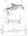
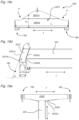
- Fig. 1 illustrates a top-lift spreader 10 for lifting an intermodal transport container.
- the spreader 10 comprises a main frame 12, which is suspended in a suspension arrangement 14 in a manner allowing the main frame 12 to slide relative to the suspension arrangement 14 along a longitudinal direction L of the main frame 12.
- the spreader 10 is configured to be carried, via a rotator 16, by a spreader carrier (not illustrated), such as a container crane or a truck.
- a spreader carrier not illustrated
- Four twist-locks 18, three of which are visible in Fig. 1 are arranged in a rectangular pattern.
- the twist-locks 18 are configured to releasably attach, in a manner known in the art, to respective lifting castings 20 of a container 22 to be lifted by the spreader 10.
- the lifting casting 20 has a short-side opening 23, a long-side opening 25, and a top opening 50 allowing the container 22 to be lifted from any direction.
- the spreader 10 is configured to telescopically translate the twist-locks 18 along the longitudinal direction L, as well as along a transversal direction T perpendicular to the longitudinal direction L, in a manner that will be elucidated with reference to Figs 2a-b .
- Figs. 2a-2b schematically illustrate the spreader 10 in two different positions, as seen from below.
- the main frame comprises a main beam 24, which is hollow and defines a first travelling beam guide 26 and a second travelling beam guide 28.
- the travelling beam guides 26, 28 are mutually parallel, and parallel to the longitudinal direction of the main frame.
- the first travelling beam guide 26 guides a first travelling beam 30, which is movable along a first travelling beam guide axis A1.
- the second travelling beam guide 28 guides a second travelling beam 32, which is movable along a second travelling beam guide axis A2.
- the spreader 10 is illustrated with the travelling beams 30, 32 fully retracted into the respective travelling beam guides 26, 28, whereas when in the position of Fig. 2b , only the proximal ends 34, 36 of the respective travelling beams 30, 32 remain in the respective travelling beam guides 26, 28.
- the first travelling beam 30 is operated by a first hydraulic cylinder 29 ( Fig. 1 ), which has a first end attached to the main beam 24 and a second end attached to the first travelling beam 32.
- the second travelling beam 32 is operated by a second hydraulic cylinder 35 ( Fig. 1 ) in a similar manner, mutatis mutandis.
- the hydraulic cylinders 29, 35 are arranged on the top face of the main beam 24, and extend along the length of the main beam 24.
- Distal ends 38, 40 of the travelling beams 30, 32 are connected to the twist locks 18 ( Fig. 1 ) in such a manner that the distal end 38 of the first travelling beam 30 carries a first twist-lock arrangement 42 comprising a first pair 18a-b of said twist-locks 18, and the distal end 40 of the second travelling beam 32 carries a second twist-lock arrangement 44 comprising a second pair 18c-d of twist-locks 18.
- a first twist-lock arrangement 42 comprising a first pair 18a-b of said twist-locks 18
- the distal end 40 of the second travelling beam 32 carries a second twist-lock arrangement 44 comprising a second pair 18c-d of twist-locks 18.
- the first pair of twist-locks consists of a first twist-lock 18a and a second twist-lock 18b.
- the second pair of twist-locks consists of a first twist-lock 18c and a second twist-lock 18d.
- the first and second pairs of twist-locks are arranged in a rectangular pattern, a long side of which extends along the longitudinal direction L and a short side of which extends along the transversal direction T, allowing the twist-locks 18a-d to engage with lifting castings 20 ( Fig. 1 ) arranged in a mating rectangular pattern on a top face of a container to be lifted.
- the first and second twist-locks 18a-b of the first pair of twist-locks are telescopically suspended in a first transversal beam 46, which interconnects the twist-locks 18a-b and the distal end 38 of the first travelling beam 30.
- the transversal distance D T between the first and second twist-locks 18a and 18b of the first pair of twist-locks can thereby be varied by moving the twist-locks 18a-b towards or away from each other along the transversal direction T.
- the first and second twist-locks 18c, 18d of the second pair are suspended in a second transversal beam 48 in a similar manner, mutatis mutandis, allowing also the transversal distance between the first and second twist-locks 18c, 18d of the second pair to be varied.
- the transversal movement of the twist-locks 18a-b of the first pair is coordinated with the transversal movement of the twist-locks 18c-d of the second pair, such that the length of the short side of the rectangular pattern can thereby be varied.
- the spreader 10 is contracted in the longitudinal and transversal directions L, T such that the rectangular pattern defined by the twist-locks 18a-d corresponds to the rectangular pattern defined by top openings 50 ( Fig. 1 ) of the lifting castings 20 of an ISO-standard 20-foot by 8-foot intermodal container.
- Fig. 2b illustrates the same spreader 10 extended in the longitudinal and transversal directions L, T such that the rectangular pattern defined by the twist-locks 18a-d corresponds to the rectangular pattern defined by the top openings of the lifting castings of a 40-foot "pallet-wide" intermodal container, which has a typical width in the transversal direction of about 8 feet 6 inches.
- the spreader can also be longitudinally extended to 40 feet while simultaneously remaining transversally contracted to eight feet, and vice versa.
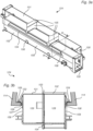
- Figs 3a-b illustrates a container spreader main beam 124 similar to a general type known in the art.
- the main beam 124 which may replace the main beam 24 and hence be integrated within a spreader 10 as described hereinbefore with reference to Figs 1 and 2a-b , is formed by a pair of rectangular HSS (Hollow Structural Section) steel beams 101, 102 of uniform material thickness.
- a typical material thickness of the HSS beams of a main beam 124 capable to withstand the weight of a laden 40-foot container may be about 12 mm.
- Each HSS beam 101, 102 defines a respective travelling beam guide 126, 128.
- the HSS beams 101, 102 are welded together along an upper longitudinal line 103 and a lower longitudinal line 104, to form the main beam 124.
- Top reinforcement bands 105 of steel plate are welded transversally across the outer top face of the main beam 124 at the predetermined, longitudinal positions along the main beam 124 where the proximal ends 34, 36 of the travelling beams 30, 32 will be located when the spreader is set in the 20- and 40-foot positions (c.f. Figs 2a-b ), respectively.
- a typical material thickness of the top reinforcement bands 105 may be about 30 mm for spreaders capable of handling laden 40-foot containers.
- Similar bottom reinforcement bands 106 are welded transversally across the outer bottom face of the main beam 124, and reinforce the bottom at the same longitudinal positions.
- a pair of side shift rails 152, 154 extend in the longitudinal direction along opposite outer side wall faces 156, 158 of the main beam 124.
- the side shift rails 152, 154 allow the main beam 124 to be slidably suspended in a suspension arrangement 114 functionally corresponding to the suspension arrangement 14 of Fig. 1 .
- Slide pads 109, attached to the suspension arrangement 114, reduce the friction in such sliding engagement, and steel plate side reinforcements 107, 108 are welded along the side wall faces 156, 158 in order to reinforce the main beam 124 against transversal loads from the suspension arrangement 114.
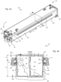
- Figs 4a-b illustrate in greater detail the main beam 24 of Figs 1 and 2a-b , wherein Fig. 4b illustrates a cross-section of the main beam 24 as seen in a plane IV-IV perpendicular to the main beam's longitudinal direction L.
- the main beam 24 of Figs 4a-b is of a lighter and stronger design than the main beam 124 of Figs 3a-b for reasons that will be elucidated in the following.
- the main beam 24 is formed of a first, upper C-beam, or channel beam, 60 of a relatively thicker material thickness MT U1 , the upper C-beam 60 being oriented with its channel facing downwards; and a second, lower C-beam 62 of a relatively thinner material thickness, MT L1 , wherein relatively thicker in this context should be construed as thicker than the relatively thinner material thickness.
- the lower C-beam 62 is oriented with its channel facing upwards, towards the channel of the upper C-beam 60, such that the channels of the upper and lower C-beams 60, 62 face each other.
- the lower C-beam 62 may have a material thickness MT L1 of less than 2/3 of the material thickness MT U1 of the upper C-beam 60.
- the lower C-beam 62 has a material thickness MT L1 of about half the material thickness MT U1 of the upper C-beam 60.
- the upper C-beam 60 may be made of steel plate having a thickness MT U1 of about 20 mm, whereas the lower C-beam 62 may be made of steel plate having a thickness MT L1 of about 10 mm.
- the lower C-beam 62 has a vertical height H L which is higher than the vertical height Hu of the upper C-beam 60.
- the upper and lower C-beams 60, 62 are welded directly together along a pair of longitudinal welds 64, 66, to form a main beam 24 of a generally rectangular cross-section.
- a vertical separation wall 37 extends between the upper and lower C-beams 60, 62, and divides the inner space defined by the upper and lower C-beams 60, 62 into said first and second travelling beam guides 26, 28, thereby making also the travelling beam guides 26, 28 substantially rectangular in cross-section.
- the separation wall 37 may be provided with a plurality of lightening holes (not shown).
- a pair of L-shaped side shift rails 52, 54 are welded to the lower C-beam 62 and extend in the longitudinal direction along opposite outer side wall faces 56, 58 of the main beam 24, thereby allowing the main beam 24 to be slidably suspended in the suspension arrangement 14.
- the thinner material thickness of the lower C-beam 62 allows the side shift rails 52, 54 to be countersunk laterally inside the outer side wall faces of the upper C-beam 60, and attached directly below the same, so as to vertically bear against the lower longitudinal edges of the upper C-beam 60. Thereby, the vertical load of the main beam 24 will be vertically applied directly onto the side shift rails 52, 54, reducing the strain on the welds connecting the side shift rails 52, 54 to the main beam 24.
- Each side shift rail 52, 54 rests in the suspension arrangement 14 on a set of slide pads 68, of which one on each side of the main beam 24 is illustrated in the cross-section of Fig. 4b .
- a set of side support pads 70 face the outer side wall faces 56, 58 above the welds 64, 66, and guide the main beam 24 along the longitudinal direction L.
- Inner bottom slide pads 72 are arranged on inner bottom faces of the respective travelling beam guides 26, 28 adjacent to their respective guide apertures 86, 88. The inner bottom slide pads 72 are configured to support the travelling beams 30, 32, and provide a distribution of the weight of the travelling beams 30, 32 across said inner bottom faces.
- slide pads 72 are attached to outer top and bottom faces of the proximal end 34, 36 of each travelling beam 30, 32.
- the slide pads 72 each have a length, in the longitudinal direction L, of about 400 mm, i.e. the total slide pad length carrying each travelling beam 30, 32 is about 800 mm.
- the main beam 24 is, at each of a first end 74 and a second end 76, provided with a respective steel plate end collar 78, 80 extending outwards from the hollow structure defined by the upper and lower C-beams along a respective plane perpendicular to the longitudinal direction L.
- the first end collar 78 encloses a beam guide aperture 82 of the first travelling beam guide 26 and partly closes a rear end opening 84 of the second travelling beam guide 28.
- the second end collar 80 encloses a beam guide aperture 88 of the second travelling beam guide 28 and partly closes a rear end opening 86 of the first travelling beam guide 26.
- Each of said end collars 78, 80 also forms a diagonal truss element 87 across the respective rear end opening 84, 86.
- Fig. 5 illustrates a cross-section of an exemplary embodiment of the first travelling beam 30.
- the second travelling beam 32 ( Fig. 2 ) may be constructed in a similar manner.
- the first travelling beam 30 is formed of a first, upper C-beam, or channel beam, 31 of a relatively thinner material thickness MT U2 , the upper C-beam 31 being oriented with its channel facing downwards; and a second, lower C-beam 33 of a relatively thicker material thickness, MT L2 , wherein relatively thicker in this context should be construed as thicker than the relatively thinner material thickness.
- the lower C-beam 33 is oriented with its channel facing upwards, towards the channel of the upper C-beam 31, such that the channels of the upper and lower C-beams 31, 33 face each other.
- the upper C-beam 31 may, for example, have a material thickness MT U2 of less than 2/3 of the material thickness MT L2 of the lower C-beam 33.
- the upper C-beam 31 has a material thickness MT U2 of about half the material thickness MT L2 of the lower C-beam 33.
- the upper C-beam 31 may be made of steel plate having a thickness MT U2 of about 10 mm, whereas the lower C-beam 33 may be made of steel plate having a thickness MT L2 of about 20 mm. Similar to the main beam 24, the upper and lower C-beams 31, 33 of the travelling beam 30 are welded together along a pair of welds extending in the longitudinal direction L.
- the proximal end 34 of the upper C-beam 31 may be provided with a reinforcement (not illustrated), which may reinforce the travelling beam 30 at its location where the proximal end 34 applies its load onto the upper, inner surface of the travelling beam guide 26 ( Fig. 4b ).
- the reinforcement may be configured as steel plate end cover at least partly closing the hollow structure defined by the upper and lower C-beams 31, 33 at the proximal end 34, similar to the collar 78, 80 of the main beam 24, or as a transversal reinforcement band, similar to the bands 105 of Fig. 3a , welded to the inside or outside surface of the upper C-beam 31 at the proximal end 34.
- Fig. 6 schematically illustrates a cross-section of yet an embodiment of a main beam 224 for a spreader, such as a side-lift spreader or the top-lift spreader 10 of Fig. 1 .
- the main beam 224 comprises an upper C-beam 260 of relatively thicker material thickness, and a lower C-beam 62 of relatively thinner material thickness.
- the upper and lower C-beams 60, 62 are rigidly attached to each other via a pair of intermediate elements 261.
- a pair of travelling beams 230, 232 are guided inside the inner space enclosed by the upper and lower C-beams 260, 262; in this respect, the main beam 224 forms a pair of parallel guides 226, 228 for the respective travelling beams 230, 232.
- the intermediate elements 261 extend inwards into the main beam 224 to form guide rails, which form-fittingly keep the travelling beams 230, 232 apart.
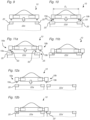
- Figs 7-12b illustrate a number of different lifting scenarios that the spreader 10 ( Fig. 1 ) may encounter when lifting a container 22.
- Each figure schematically illustrates the spreader from the side, as seen along the longitudinal direction, and hence illustrates a transversal beam 46 provided with a respective pair of telescopically arranged twist-locks 18a-b.
- Fig. 7 illustrates the spreader when set in an ISO standard position mode, i.e. its transversal centre-to-centre distance D T between the male locking inserts 19a-b of the twist-locks 18a-b is adjusted for lifting an ISO standard container having a width of 8 feet.
- the container 22a to be lifted is an ISO standard container having a width in the transversal direction T of 8 feet.
- Fig. 8 illustrates the spreader 10 when set in a "wide twist-lock position", WTP, mode, i.e. its transversal centre-to-centre distance D T between the male locking inserts 19a-b of the twist-locks 18a-b is adjusted for lifting a so-called "pallet-wide container” or "wide-body container”.
- the pallet-wide container 22b to be lifted has a width in the transversal direction T adapted for accommodating two standardized pallets next to each other, and therefore is slightly wider than an ISO container. It has a width in the transversal direction T of about 8 feet and 6 inches.
- the pallet-wide container 22b has its lifting castings separated by 6 inches more than an ISO standard container, and may therefore be termed a WTP pallet-wide container.
- Fig. 9 illustrates the spreader 10 set in the ISO standard position mode.
- the container 22c to be lifted is of a first type of pallet-wide container with lifting castings 20 in ISO position. Thanks to having its lifting castings 20 in the more common ISO position, the intermodal container 22c can, as it is moved by different trucks and cranes along its route of transport, be lifted by spreaders capable of handling ISO containers only.
- the container 22c has a wider body of about 8 feet and 6 inches, but the transversal distance between its top corner castings 20 is the same as that of ISO containers.
- Fig. 10 again illustrates the spreader 10 set in the ISO standard position mode.
- the container 22d to be lifted is of a second type of pallet-wide container with lifting castings 20 in ISO position.
- the container 22d differs from the container 22c of Fig. 9 in that the lifting castings 20 extend outwards to the full width of the pallet-wide container body, allowing the lifting castings 20 to be accessed also from the side by e.g. a side-lift spreader (not illustrated), whereas the top openings 50 (illustrated schematically with dashed lines) are separated by a centre-to-centre distance D T corresponding to the centre-to-centre distance between the male locking inserts 19a-b when the spreader 10 is in ISO position.
- This allows the container 22d to be lifted by the spreader 10 in ISO position, even though the container 22d has a wider body of about 8 feet and 6 inches.
- Fig. 11a illustrates a first potentially dangerous situation.
- the container 22d is again of the second type of pallet-wide container with lifting castings 20 in ISO position, which is described with reference to Fig. 10 .
- the spreader 10 is erroneously set in WTP mode; this may, by way of example, happen due to human mistake.
- the locations of the top openings 50 are not visible from below. It is very difficult, and in some situations impossible, to see the difference between a WTP wide-body container 22b ( Fig. 8 ), and said second type of pallet-wide container 22d ( Fig. 10 ) with lifting castings 20 in ISO position, from e.g. a reach stacker below a stack of containers. Therefore, a reach stacker truck driver will generally have to read, and rely on, container type codes written on the containers for their type identification. Container type codes may also be worn or otherwise difficult to read.
- container type codes require knowledge and skill, and also requires the reach stacker driver to be attentive and focussed.
- the male part 19a of the first twist-lock 18a is inserted into the respective lifting casting 20, whereas the male part 19b of the second twist-lock 18b is lowered just outside the container 22d. Twisting the twist-locks to their lock positions, and thereafter lifting the spreader 10, will damage the container 22d, and may also result in dropping the container 22d to the ground. In particular, the latter may occur if the second male part 19b engages with a long-side opening 25 ( Fig. 1 ) of the lifting casting 20, allowing the container 22d to follow the spreader 10 up as it is lifted.
- Fig. 12a illustrates a second potentially dangerous situation.
- the containers 22a, 22a' are standard ISO dimension containers of the type described with reference to Fig. 7 .
- the spreader 10 is erroneously set in WTP mode; this may, by way of example, happen due to human mistake.
- the male part 19a of the first twist-lock 18a is inserted into the respective lifting casting 20, whereas the second twist-lock 18b is lowered onto the lifting casting 20' of an adjacent container 22a', with its male locking insert 19b just outside the adjacent container 22a'. Locking and lifting the spreader 10 from this position may damage the containers 22a, 22a', and could potentially also result in dropping the container 22a to the ground.
- Fig. 13 illustrates a twist-lock 18 capable of avoiding the dangerous situations of Figs 11a-b and 12a-b .
- the twist-lock 18 comprises a male locking insert 19 configured to be inserted into a top opening 50 ( Fig. 1 ) of a respective lifting casting 20.
- an end portion 89 of the male locking insert 19 is configured to be twisted 90° about a vertical axis R to a lock position, in which it engages with the lifting casting 20.
- An abutment face 90 (hatched), flanking the male locking insert 19, corresponds to the size and shape of the top surface 27 ( Fig. 1 ) of the lifting casting 20, and is configured to rest thereupon once the spreader 10 ( Fig.
- a first landing indicator 91 has a vertically movable indicator body 92, a portion of which protrudes downwards from the abutment face 90.
- the indicator body 92 is located on a distal side 90a of the male locking insert 19, i.e. outside the male locking insert 19 along the transversal direction T.
- the first landing indicator 91 is configured to indicate when the upper surface 27 of the lifting casting 20 presses the vertically movable indicator body 92 vertically into the abutment face 90 of the twist-lock 18, as the abutment face 90 is lowered into abutment on the respective lifting casting top surface 27.
- a second landing indicator 93 has a vertically movable indicator body 94, a portion of which protrudes downwards from the abutment face 90.
- the indicator body 94 is located on a proximal side 90b of the male locking insert 19, i.e. inside the male locking insert 19 along the transversal direction T.
- the second landing indicator 93 is configured to indicate when the upper surface 27 of the lifting casting 20 presses the vertically movable indicator body 94 vertically into the abutment face 90 of the twist-lock, as the abutment face 90 is lowered onto the lifting casting top surface 27. Thereby, the second landing indicator 93 allows verifying that a transversally proximal portion 90b of the abutment face 90 rests upon a lifting casting 20, before the twist-lock 18 is locked. This facilitates avoiding the potentially dangerous situation of Figs 12a-b .
- Figs 14-15 illustrate the geometry, as the twist-lock 18 lands on the lifting casting 20, in greater detail.
- the indicator body 92 of the first landing indicator 91 is located transversally outside a transversally outer edge of the male locking insert 19, so as to detect the presence of a portion of the upper surface 27 of the lifting casting 20 transversally outside a transversally outer edge 85b of the top opening 50.
- the first landing indicator 91 be configured to detect the presence of a portion of the upper surface 27 of the lifting casting 20 transversally outside a transversally inner edge 85a of the top opening 50.
- the indicator body 92 located at the illustrated position transversally outside the male locking insert 19, it may, as an alternative, be located transversally aligned with the male locking insert 19.
- the indicator body 94 of the second landing indicator 93 is located transversally inside a transversally inner edge of the male locking insert 19, so as to detect the presence of a portion of the upper surface 27 of the lifting casting 20 transversally inside a transversally inner edge 85a of the top opening 50.
- the second landing indicator 93 be configured to detect the presence of a portion of the upper surface 27 of the lifting casting 20 transversally inside a transversally outer edge 85a of the top opening 50.
- the indicator body 94 located at the illustrated position transversally inside the male locking insert 19, it may, as an alternative, be located transversally aligned with the male locking insert 19.
- a single indicator body transversally aligned with the male locking insert may, in fact, assist in avoiding both potentially dangerous situations of Figs 11b and 12b .
- Fig. 16 illustrates the second landing indicator 93 in greater detail.
- the rotatable male locking insert end portion 89 is provided with a blocking pin 96 extending radially from an upper portion of the male locking insert end portion 89.
- the vertically movable indicator body 94 comprises a blocking element 95 shaped to, when in the lower position as illustrated in Fig. 16 , mechanically block the blocking pin 96 from swinging past the blocking element 95, and thereby mechanically block the male locking insert end portion 89 from turning to the lock position.
- the indicator body 94 is resiliently biased towards a lower position in which it protrudes from the abutment face 90.
- FIG. 17a The cross-sections of Figs 17a-b illustrate the first landing indicator 91 in greater detail.
- the indicator body 92 is in a lower position, in which it protrudes below the abutment face 90
- Fig. 17b illustrates the indicator body 92 in an upper position, in which it is flush with the abutment face 90.
- a spring 97 applies a bias, pressing the indicator body 92 towards its lower position.
- the indicator body 92 is shaped as a U-shaped loop, comprising a first loop leg 98a and a second loop leg 98b, said legs 98a-b extending upwards from an intermediate portion 99 interconnecting the loop legs 98a-b, wherein each loop leg 98a-b is guided in the vertical direction by a respective loop leg guide 100.
- An elongate track 41 in the abutment face 90 allows the intermediate portion 99 of the indicator body 92 to be received therein in its entirety.
- the first loop leg 98a which is located outside the vertical projection (dotted area) of the abutment face 90, is provided with a washer 43.
- An inductive sensor 45 is configured to detect the presence of the washer 43 when the loop 92 is in its upper position.
- the inductive sensor 45 is connected to an electronic control system 39 of the spreader 10, which may in turn be connected to the control system of any truck or crane carrying the spreader.
- the control systems may be provided with an electronic landing indication indicating whether the transversally outer portion of the abutment face 90 abuts the upper surface 27 of a lifting casting 20.
- the second loop leg 98b is a simple stub, serving for preventing the indicator body 92 from turning about the first loop leg 98a.
- the electronic landing signal, or the absence of an electronic landing signal may be used for allowing or prohibiting the operation of the twist-locks. Alternatively, the electronic landing signal may be indicated to an operator, such as a reach stacker driver.
- Fig. 18 illustrates the second hydraulic cylinder 35 ( Fig.
- the hydraulic cylinder 35 is incorporated in a hydraulic cylinder assembly 1001, and has a first end 1003 attached to a top face of the main beam 24 ( Fig. 1 ), and a second end 1005 attached to a top face of the second twist-lock arrangement 44 ( Fig. 2b ) at the distal end 40 of the second travelling beam 32.
- the hydraulic cylinder assembly 1001 comprises a hydraulic connection assembly 1007 comprising a plurality of hydraulic hoses 1009.
- the hydraulic connection assembly 1007 comprises seven hydraulic hoses 1009a-g, two of which 1009a-b are hydraulically connected to the hydraulic cylinder 35 adjacent to the respective ends 1003, 1005, to control the hydraulic cylinder 35 in both directions.
- the remaining five hydraulic hoses 1009c-g are configured to forward respective hydraulic control signals to hydraulic actuators other than the hydraulic cylinder 35, such as the first hydraulic cylinder 29 ( Fig. 1 ), any hydraulic cylinders (not shown) for moving the twist-locks 18 between standard position mode ( Fig. 7 ) and wide twist-lock position mode ( Fig. 8 ), and hydraulic actuators for turning the insert end portions 89 of the twist-locks 18 ( Fig. 13 ).
- the hydraulic cylinder 35 doubles as a carrier for hydraulic connections 1009c-g unrelated to the function of the hydraulic cylinder 35.
- the hydraulic control connection assembly 1007 is attached to the hydraulic cylinder 35 at a plurality of attachment positions 1011 distributed along the length of the hydraulic cylinder 35, such that the hydraulic hoses 1009 require no or very few attachment points directly onto the main beam 24 ( Fig. 1 ).
- the hydraulic cylinder assembly 1001 can be assembled before attaching it to the main frame 12 ( Fig. 1 ). This saves valuable time for assembling the spreader 10 ( Fig. 10 ), as well as substantially reduces the amount of threaded attachment holes needed in the main beam 24 ( Fig. 1 ).
- Figs 19a-e illustrate an alternative embodiment of a transversal beam 346, which may replace any of the transversal beams 46, 48 of the spreader 10 ( Fig. 1 ). Similar to the transversal beam 46, the transversal beam 346 interconnects a pair of twist-locks 18a-b. For reasons of clarity of illustration, the transversal beam 346 is illustrated as non-telescopic, even though the transversal beam structure described hereinbelow may equally well be applied to a telescopic transversal beam such as the beam 46 described hereinbefore.
- the male locking inserts 19 ( Fig. 13 ) of the twist-locks are, also for reasons of clarity of illustration, not illustrated in Figs 19a -f.
- the transversal beam 346 is connected to a longitudinal beam 330, which may be telescopically or fixedly attached to the main frame of the spreader 10 ( Fig. 1 ).
- the transversal beam 346 comprises an outer side wall 2001, an inner side wall 2003, a bottom wall 2005, and a top wall 2007, which are welded together to define a hollow structural section, HSS, structure extending in the transversal direction T.
- the HSS structure has a cross-section which varies along the length of the transversal beam 346 in the transversal direction T in such a manner that its vertical height H T decreases towards the ends of the transversal beam 346.
- the transversal beam portions exhibiting a gradual height decrease extend in each direction to respective positions P located about 1/10 * L T from the transversal beam's 346 ends.
- the gradually decreasing height H T is defined by respective inclined upper edges 2013, 2015 of the outer and inner side walls 2001, 2003.
- the upper edges 2015, 2013 of the inner and outer side walls 2003, 2001 are interconnected by an upper top wall 2007 extending along the length of the upper edges 2013, 2015.
- the longitudinal beam 330 penetrates through the inner side wall 2003 and into abutment with the outer side wall 2001, and is attached to both side walls 2001, 2003 by means of respective welds extending about the circumference of the longitudinal beam 330.
- An inner edge 2009 of the bottom wall 2005 extends inwards, beyond the inner side wall, to define an inwardly extending flange 2011.
- the flange 2011 has a width W F , in the longitudinal direction, which gradually increases towards the location where the longitudinal beam 330 interfaces the transversal beam 346, and is welded to the longitudinal beam 330 via a pair of supports 2017.
- Each of the inner and outer side walls 2001, 2003 has a respective upper wall portion 2001a, 2003a which is inclined longitudinally inwards, so as to form an acute angle ⁇ with a plane defined by the four twist-locks 18 ( Fig. 1 ).
- the inclined upper wall portions 2001a, 2003a are parallel to each other, and their top edges 2013, 2015 substantially coincide with each other as seen along the longitudinal direction L of the spreader 10.
- Each of the inner and outer side walls 2001, 2003 also has a respective lower wall portion 2001b, 2003b which extends along a respective substantially vertical plane, so as to form an obtuse angle ⁇ with the respective upper side wall 2001a, 2003a.
- the lower wall portions 2001b, 2003b are parallel to each other.
- the longitudinal beam 330 engages with, and is welded to, upper and lower wall portions 2001a-b, 2003a-b of both side walls 2001, 2003, resulting in a very rigid structure.
Landscapes
- Engineering & Computer Science (AREA)
- Mechanical Engineering (AREA)
- Architecture (AREA)
- Automation & Control Theory (AREA)
- Civil Engineering (AREA)
- Structural Engineering (AREA)
- Load-Engaging Elements For Cranes (AREA)
- Forklifts And Lifting Vehicles (AREA)
Claims (13)
- Anschlaggeschirr (10) zum Heben eines intermodalen Transportcontainers (22, 22a-d), wobei das Anschlaggeschirr (10) Folgendes umfasst:einen Hauptrahmen (12), der eine erste Laufträgerführung (26; 226) und, angrenzend an die erste Laufträgerführung (26; 226), eine zweite Laufträgerführung (28; 228) umfasst,einen ersten Laufträger (30; 230), der ein proximales Ende (34), das in der ersten Lauf träger führung (26; 226) geführt wird, um so eine Bewegung entlang einer ersten Führungsachse (A1) zu ermöglichen, und ein distales Ende (38), das mit einer ersten Drehverschlussanordnung (42) versehen ist, aufweist, undeinen zweiten Laufträger (32; 232), der ein proximales Ende (36), das in der zweiten Lauf träger führung (28; 228) geführt wird, um so eine Bewegung entlang einer zweiten Führungsachse (A2) zu ermöglichen, wobei die erste und die zweite Führungsachse (A1, A2) parallel sind, und ein distales Ende (40), das mit einer zweiten Drehverschlussanordnung (44) versehen ist, aufweist,wobei die distalen Enden (38, 40) der Laufträger (30, 32) dafür konfiguriert sind, sich veränderlich von den jeweiligen Laufträgerführungen (26; 226, 28; 228) aus in entgegengesetzten Richtungen zu erstrecken, um so ein Ändern des axialen Abstandes (DL) zwischen der ersten und der zweiten Drehverschlussanordnung (42, 44) zu ermöglichen, um sich an Container (22, 22a-d) mit unterschiedlichen axialen Längen anzupassen,wobei das Anschlaggeschirr dadurch gekennzeichnet ist, dass der Hauptrahmen (12) einen Hauptträger (24) umfasst, der von Folgendem gebildet wird:einem ersten, oberen, C-Träger (60; 260) mit einer verhältnismäßig dickeren Materialstärke (MTU1), wobei der obere C-Träger (60; 260) so ausgerichtet ist, dass er einen nach unten zeigenden Kanal definiert, undeinem zweiten, unteren, C-Träger (62; 262) mit einer verhältnismäßig dünneren Materialstärke (MTL1),wobei die verhältnismäßig dickere Materialstärke (MTU1) dicker ist als die verhältnismäßig dünnere Materialstärke (MTL1),wobei der untere C-Träger (62; 262) so ausgerichtet ist, dass er einen nach oben zeigenden Kanal definiert, wobei der obere und der untere C-Träger (60; 260, 62; 262) zueinander zeigen, um einen inneren Raum zu definieren, der den oberen und den unteren Kanal umfasst.
- Anschlaggeschirr nach Anspruch , das ferner eine vertikale Trennwand (37) umfasst, die den inneren Raum in die erste und die zweite Laufträgerführung (26; 226, 28; 228) unterteilt.
- Anschlaggeschirr nach einem der vorhergehenden Ansprüche, wobei die erste und die zweite Drehverschlussanordnung (42, 44) beweglich sind zwischen einer 20-Fuß-Stellung, in welcher der axiale Abstand (DL) zwischen der ersten und der zweiten Drehverschlussanordnung (42, 44) angepasst ist zum Ineinandergreifen mit den Eckgussbeschlägen (20) eines 20-Fuß-ISO-Containers, und einer 40-Fuß-Stellung, in welcher der axiale Abstand (DL) zwischen der ersten und der zweiten Drehverschlussanordnung (42, 44) angepasst ist zum Ineinandergreifen mit den Eckgussbeschlägen (20) eines 40-Fuß-ISO-Containers.
- Anschlaggeschirr nach einem der vorhergehenden Ansprüche, wobei der obere und der untere C-Träger (60; 260, 62; 262) entlang eines Paares von Längsschweißverbindungen (64, 66) aneinandergeschweißt sind.
- Anschlaggeschirr nach einem der vorhergehenden Ansprüche, wobei die vertikale Höhe (HU) des oberen C-Trägers (60; 260) niedriger ist als die vertikale Höhe (HL) des unteren C-Trägers (62; 262).
- Anschlaggeschirr nach einem der vorhergehenden Ansprüche, wobei sowohl die erste als auch die zweite Laufträgerführung (26; 226, 28; 228) einen rechteckigen Querschnitt aufweist.
- Anschlaggeschirr nach einem der vorhergehenden Ansprüche, das ferner eine Trägeraufhängungsanordnung (14) umfasst, wobei der Hauptträger (24) in der Trägeraufhängungsanordnung (14) aufgehängt ist und ein Paar von gegenüberliegenden äußeren Seitenwandflächen (56, 58) umfasst, wobei jede äußere Seitenwandfläche (56, 58) mit einer jeweiligen seitlichen Verschiebungsschiene (52, 54) versehen ist, die von derselben aus vorspringt und sich entlang einer Längsrichtung (L) des Hauptträgers (24) erstreckt, wobei jede seitliche Verschiebungsschiene (52, 54) auf einer jeweiligen vertikalen Abstützung (68) der Aufhängungsanordnung (14) aufliegt, um so ein Bewegen des Hauptträgers (24) auf den vertikalen Abstützungen (68) in der Längsrichtung (L) zu ermöglichen, wobei der Hauptträger (24) entlang der Längsrichtung (L) durch ein Paar von seitlichen Abstützungen (70) geführt wird, die zu den jeweiligen äußeren Seitenwandflächen (56, 58) zeigen.
- Anschlaggeschirr nach Anspruch 7, wobei die seitlichen Abstützungen (68) dafür konfiguriert sind, den Hauptträger (14) auf der Höhe des oberen C-Trägers (60) zu führen.
- Anschlaggeschirr nach einem der vorhergehenden Ansprüche, wobei jeder der Laufträger (30, 32) über eine Gleitblockanordnung (72) auf einer inneren unteren Fläche der jeweiligen Laufträgerführung (26, 28) aufliegt, wobei jede Gleitblockanordnung (72) eine Gesamtlänge entlang der jeweiligen Führungsachse (A1, A2) von mindestens 300 mm aufweist.
- Anschlaggeschirr nach einem der vorhergehenden Ansprüche, wobei der Hauptträger (24) ein erstes Ende (74), an dem der erste Laufträger (30) dafür konfiguriert ist, sich von einer Laufträgeröffnung (82) der ersten Laufträgerführung (26) aus zu erstrecken, und ein zweites Ende (76), an dem der zweite Laufträger (32) dafür konfiguriert ist, sich von einer Laufträgeröffnung (88) der zweiten Laufträgerführung (28) aus zu erstrecken, aufweist, wobeidas erste Ende (74) des Hauptträgers (24) mit einem ersten Stahlplatten-Endbund (78) versehen ist, der die erste Laufträger-Führungsöffnung (82) umschließt und eine hintere Endöffnung (84) der zweiten Laufträgerführung (28) zumindest teilweise verschließt, unddas zweite Ende (76) des Hauptträgers (24) mit einem zweiten Stahlplatten-Endbund (80) versehen ist, der die zweite Laufträger-Führungsöffnung (88) umschließt und eine hintere Endöffnung (86) der ersten Laufträgerführung (26) zumindest teilweise verschließt.
- Anschlaggeschirr nach einem der vorhergehenden Ansprüche, wobei die erste und die zweite Drehverschlussanordnung (42, 44) dafür konfiguriert sind, mit Hebegussbeschlägen (20) an einer oberen Fläche des Containers (22) ineinanderzugreifen.
- Verfahren zum Herstellen eines Anschlaggeschirrträgers eines Anschlaggeschirrs nach einem der vorhergehenden Ansprüche, das Folgendes umfasst:Bereitstellen eines ersten C-Trägers (60) mit einer verhältnismäßig dickeren Materialstärke, wobei der erste C-Träger (60), gesehen im Querschnitt, einen Stegabschnitt umfasst, der ein Paar von Flanschen miteinander verbindet, die sich in der gleichen allgemeinen Richtung von demselben aus erstrecken,Bereitstellen eines zweiten C-Trägers (62) mit einer verhältnismäßig dünneren Materialstärke, wobei der zweite C-Träger (62), gesehen im Querschnitt, einen Stegabschnitt umfasst, der ein Paar von Flanschen miteinander verbindet, die sich in der gleichen allgemeinen Richtung von demselben aus erstrecken, undSchweißen der Flansche des ersten C-Trägers (60) an die Flansche des zweiten C-Trägers (62) entlang einer Längsrichtung (L) der C-Träger (60, 62), um so einen länglichen Raum zu formen, der durch die Flansche und die Stegabschnitte der C-Träger (60, 62) eingeschlossen wird.
- Verfahren nach Anspruch 12, das ferner das Schweißen eines inneren Wandelements (37) an den Stegabschnitt des ersten C-Trägers (60) entlang der Längsrichtung (L) und
das Schweißen des inneren Wandelements (37) an den Stegabschnitt des zweiten C-Trägers (62) entlang der Längsrichtung (L) umfasst.
Priority Applications (1)
| Application Number | Priority Date | Filing Date | Title |
|---|---|---|---|
| EP23180508.6A EP4253682A3 (de) | 2016-02-01 | 2016-02-01 | Spreizer zum heben eines intermodalen behälters |
Applications Claiming Priority (1)
| Application Number | Priority Date | Filing Date | Title |
|---|---|---|---|
| PCT/SE2016/050070 WO2017135851A1 (en) | 2016-02-01 | 2016-02-01 | Spreader for lifting intermodal container |
Related Child Applications (1)
| Application Number | Title | Priority Date | Filing Date |
|---|---|---|---|
| EP23180508.6A Division EP4253682A3 (de) | 2016-02-01 | 2016-02-01 | Spreizer zum heben eines intermodalen behälters |
Publications (3)
| Publication Number | Publication Date |
|---|---|
| EP3411320A1 EP3411320A1 (de) | 2018-12-12 |
| EP3411320A4 EP3411320A4 (de) | 2019-08-14 |
| EP3411320B1 true EP3411320B1 (de) | 2023-07-26 |
Family
ID=59500463
Family Applications (2)
| Application Number | Title | Priority Date | Filing Date |
|---|---|---|---|
| EP23180508.6A Pending EP4253682A3 (de) | 2016-02-01 | 2016-02-01 | Spreizer zum heben eines intermodalen behälters |
| EP16889565.4A Active EP3411320B1 (de) | 2016-02-01 | 2016-02-01 | Spreizer zum heben eines intermodalen behälters |
Family Applications Before (1)
| Application Number | Title | Priority Date | Filing Date |
|---|---|---|---|
| EP23180508.6A Pending EP4253682A3 (de) | 2016-02-01 | 2016-02-01 | Spreizer zum heben eines intermodalen behälters |
Country Status (6)
| Country | Link |
|---|---|
| US (3) | US10968081B2 (de) |
| EP (2) | EP4253682A3 (de) |
| CN (2) | CN108602651B (de) |
| MY (1) | MY198132A (de) |
| PL (1) | PL3411320T3 (de) |
| WO (1) | WO2017135851A1 (de) |
Families Citing this family (15)
| Publication number | Priority date | Publication date | Assignee | Title |
|---|---|---|---|---|
| US10968081B2 (en) * | 2016-02-01 | 2021-04-06 | Elme Spreader Ab | Spreader for lifting intermodal container |
| JP6967537B2 (ja) * | 2016-06-29 | 2021-11-17 | ヴェスタス ウィンド システムズ エー/エス | アセンブリ、設備パッケージ、及び風力タービンタワーにおける設備ユニットの設置に用いる方法 |
| KR20190037257A (ko) * | 2016-09-23 | 2019-04-05 | 에스에이취 테크놀로지스 피티이 리미티드 | 건축 시스템 및 방법 |
| DE102018205933A1 (de) * | 2018-04-18 | 2019-10-24 | Amova Gmbh | Teleskopaufnahme zum Verlagern von Containern in Hochregallagern |
| US10759635B2 (en) * | 2018-06-05 | 2020-09-01 | Abraham Ben Seutter | SIDAS—spreader impact damage avoidance system |
| WO2020073076A1 (en) * | 2018-10-10 | 2020-04-16 | Container Rotation Systems Pty Ltd | A cargo container handling apparatus and method of transferring bulk material |
| FI128652B (fi) | 2018-12-19 | 2020-09-30 | Konecranes Global Oy | Köysinostimen nostovaunu |
| JP2023518324A (ja) * | 2019-05-07 | 2023-04-28 | ピーター・キャノン・ホールディングス・ピーティーワイ・リミテッド | Isoコンテナの取扱及び保管のためのシステム |
| EP3760570B1 (de) * | 2019-07-05 | 2022-04-27 | CAMCO Technologies NV | Behälterabtastsystem mit waschstation |
| SE544520C2 (en) * | 2020-03-30 | 2022-06-28 | Elme Spreader Ab | Spreader system, spreader, and method of handling a transport container using a spreader |
| SE544521C2 (en) * | 2020-03-30 | 2022-06-28 | Elme Spreader Ab | Spreader, container handling equipment comprising spreader, and method of lifting a transport container |
| CN111606214B (zh) * | 2020-06-04 | 2021-02-23 | 西南交通大学 | 一种集装箱用门式起重机 |
| CN112357757B (zh) * | 2020-12-14 | 2022-09-09 | 山东晟天钢构有限公司 | 航车梁组件及配套的航车系统 |
| CN114030986B (zh) * | 2021-11-23 | 2023-10-03 | 中国矿业大学 | 一种用于井下辅助运输系统转载物料的吊具及方法 |
| CN116216487B (zh) * | 2023-03-20 | 2023-09-15 | 中铁四局集团有限公司 | 一种可适配曲率的pc轨道梁吊具 |
Family Cites Families (45)
| Publication number | Priority date | Publication date | Assignee | Title |
|---|---|---|---|---|
| GB1328101A (en) * | 1969-09-02 | 1973-08-30 | Lancer Boss Ltd | Lifting apparatus |
| US3788680A (en) * | 1972-06-21 | 1974-01-29 | Us Navy | Ordnance handling device |
| US3874719A (en) * | 1972-11-20 | 1975-04-01 | Clark Equipment Co | Extensible load lifting frame |
| SE382439B (sv) * | 1974-06-05 | 1976-02-02 | Backtemans Patenter Ab | Lyftok |
| US4093090A (en) * | 1974-11-29 | 1978-06-06 | Rpc Corporation | Spreader for lifting containers |
| SE420483B (sv) * | 1979-05-09 | 1981-10-12 | Scal Sweden Ab | Lyftanordning for container eller liknande, der ett stativ eller liknande forefinnes |
| US4245271A (en) * | 1979-05-18 | 1981-01-13 | Gwin Steve W | Crane system or cargo containers |
| DE3010666C2 (de) * | 1980-03-20 | 1984-08-09 | Heiko 2800 Bremen Schroeder | Ladegeschirr, insbesondere Spreader |
| EP0052119A1 (de) * | 1980-05-23 | 1982-05-26 | Ab Backtemans Patenter | Spreader |
| US4462627A (en) * | 1982-03-15 | 1984-07-31 | Cranston Machinery Co., Inc. | Lift frame assembly |
| DE3543951C2 (de) * | 1985-12-12 | 1995-12-21 | Kinshofer Greiftechnik | Greifer mit zwei Schalen oder mit Greiferarmen |
| SE454689B (sv) * | 1986-09-30 | 1988-05-24 | Karlsson Goesta | Anordning vid kombiok avsedda for hantering av containrar och trailers |
| SE8900871D0 (sv) * | 1989-03-13 | 1989-03-13 | Sea Flats Ab | Anordning vid containerhanteringsvagn |
| US5052734A (en) * | 1990-04-17 | 1991-10-01 | Paceco Corp. | Lifting spreader compensating mechanism |
| US5280980A (en) * | 1992-12-24 | 1994-01-25 | Earl's Industries Ltd. | Self-aligning twin container spreader |
| NL9301982A (nl) * | 1993-11-16 | 1995-06-16 | Robert Marie Lubbers | Werkwijze voor het transporteren van een container en transportmiddelen voor het uitvoeren van de werkwijze. |
| NL9400611A (nl) * | 1994-04-18 | 1995-12-01 | Mandigers Bv | Hefinrichting. |
| US5522633A (en) * | 1995-02-21 | 1996-06-04 | Massi; Nathaniel G. | Material handler |
| SE9500843L (sv) * | 1995-03-14 | 1996-04-29 | Elmhults Konstruktions Ab | Containerok |
| DE19549268C1 (de) | 1995-12-28 | 1997-07-31 | Mannesmann Ag | Träger in Kastenbauweise, insbesondere Kranausleger bzw. Teleskopausleger und Verfahren zum Herstellen eines Trägers |
| KR19980072609A (ko) * | 1997-03-06 | 1998-11-05 | 박정인 | 모서리 끼움쇠 주위의 파손방지 구조를 가지는 컨테이너 |
| KR100306297B1 (ko) * | 1999-05-19 | 2001-09-24 | 한만엽 | 갠트리 크레인의 동력전달시스템 |
| MXPA02000591A (es) * | 1999-07-15 | 2003-07-21 | Gimetsi Oy | Sistema y metodo para controlar los movimientos de un dispositivo para manipulacion de contenedores. |
| WO2001089979A1 (en) * | 2000-05-24 | 2001-11-29 | Stinis Beheer B.V. | Container gripping device having contact elements for braking |
| DE10041932B4 (de) * | 2000-08-27 | 2012-07-12 | Fm Patentverwertung Kg | Laschkorb zum sicheren Lösen und Verriegeln von Twistlocks |
| FI110238B (fi) | 2001-01-31 | 2002-12-31 | Innowork Oy | Menetelmä kotelopalkin valmistamiseksi sekä menetelmän mukaan valmistettu kotelopalkki ja kotelopalkin rakenneosa |
| WO2003037775A1 (en) * | 2001-10-29 | 2003-05-08 | Gimetsi Oy | Apparatus for a locking unit of a container spreader |
| US6991274B2 (en) * | 2002-05-28 | 2006-01-31 | Metropolitan Stevedore Company | Cargo cage and spreader attachment and method of use |
| AU2003238489A1 (en) * | 2002-06-10 | 2003-12-22 | Stinis Beheer B.V. | Hoisting frame and method for its use |
| JP3789402B2 (ja) * | 2002-06-26 | 2006-06-21 | 昌克 内田 | 建築鉄骨構造物の柱梁接合部交差方法 |
| JP2005112514A (ja) | 2003-10-06 | 2005-04-28 | Tadano Ltd | 伸縮ブーム |
| US7240936B2 (en) * | 2003-12-16 | 2007-07-10 | Wastequip, Inc. | Lid locking mechanism for a spreader twistlock |
| SE527325C2 (sv) * | 2004-07-05 | 2006-02-14 | Elmhults Konstruktions Ab | Containerok |
| SG138500A1 (en) * | 2006-07-05 | 2008-01-28 | Nsl Engineering Pte Ltd | Detection frame for a lifting device |
| DE102007024664B3 (de) * | 2007-05-25 | 2008-07-17 | Noell Mobile Systems Gmbh | Vorrichtung zum Längsverstellen eines Spreaders |
| US20090252569A1 (en) * | 2008-04-08 | 2009-10-08 | Walker Peter J | System for securing containers with multiple embodiments |
| SE534186C2 (sv) * | 2009-09-04 | 2011-05-24 | Elme Spreader Ab | Containerok för lyftning och centrering av containrar |
| SE535156C2 (sv) * | 2010-01-14 | 2012-05-02 | Elme Spreader Ab | Linstyrt containerok |
| WO2013060778A1 (en) * | 2011-10-26 | 2013-05-02 | Apm Terminals Bv | A device for lifting unitized cargo |
| CN202414949U (zh) * | 2011-11-29 | 2012-09-05 | 李怀昌 | 一种伸缩式集装箱吊具 |
| CN103130088A (zh) * | 2011-11-29 | 2013-06-05 | 李怀昌 | 一种伸缩式集装箱吊具 |
| DE102012010248A1 (de) * | 2012-05-24 | 2013-11-28 | CES Containerhandling Equipment & Solutions GmbH | Lastumschlag-Fahrzeug und Verfahren zur Bestimmung einer Gewichtsverteilung einer Last an einem Lastumschlag-Fahrzeug |
| US10968081B2 (en) * | 2016-02-01 | 2021-04-06 | Elme Spreader Ab | Spreader for lifting intermodal container |
| US10280055B2 (en) * | 2017-05-02 | 2019-05-07 | William von Eberstein | Ball joint lifting assembly and method |
| CN111606214B (zh) * | 2020-06-04 | 2021-02-23 | 西南交通大学 | 一种集装箱用门式起重机 |
-
2016
- 2016-02-01 US US16/071,482 patent/US10968081B2/en active Active
- 2016-02-01 EP EP23180508.6A patent/EP4253682A3/de active Pending
- 2016-02-01 CN CN201680080758.8A patent/CN108602651B/zh active Active
- 2016-02-01 WO PCT/SE2016/050070 patent/WO2017135851A1/en active Application Filing
- 2016-02-01 CN CN202110552057.2A patent/CN113173497A/zh active Pending
- 2016-02-01 PL PL16889565.4T patent/PL3411320T3/pl unknown
- 2016-02-01 EP EP16889565.4A patent/EP3411320B1/de active Active
- 2016-02-01 MY MYPI2018001316A patent/MY198132A/en unknown
-
2021
- 2021-03-23 US US17/209,610 patent/US11492234B2/en active Active
-
2022
- 2022-09-28 US US17/954,853 patent/US11981543B2/en active Active
Also Published As
| Publication number | Publication date |
|---|---|
| EP4253682A2 (de) | 2023-10-04 |
| EP4253682A3 (de) | 2023-11-01 |
| WO2017135851A1 (en) | 2017-08-10 |
| PL3411320T3 (pl) | 2024-01-03 |
| US11492234B2 (en) | 2022-11-08 |
| EP3411320A4 (de) | 2019-08-14 |
| EP3411320A1 (de) | 2018-12-12 |
| US20190077638A1 (en) | 2019-03-14 |
| CN113173497A (zh) | 2021-07-27 |
| CN108602651A (zh) | 2018-09-28 |
| US10968081B2 (en) | 2021-04-06 |
| US20210206604A1 (en) | 2021-07-08 |
| CN108602651B (zh) | 2021-05-14 |
| US11981543B2 (en) | 2024-05-14 |
| MY198132A (en) | 2023-08-07 |
| US20230027301A1 (en) | 2023-01-26 |
Similar Documents
| Publication | Publication Date | Title |
|---|---|---|
| EP3411320B1 (de) | Spreizer zum heben eines intermodalen behälters | |
| US20030198552A1 (en) | Freight container and lift casting therefore and method for lifting and transporting same | |
| US9067523B2 (en) | Container auto-lock system | |
| US8827612B2 (en) | Container auto-lock system | |
| US4537540A (en) | Transport frames for vehicles | |
| EP1204573B1 (de) | Frachtcontainer | |
| CN104837725A (zh) | 平支架 | |
| RU203169U1 (ru) | Устройство для перевозки крупнотоннажных контейнеров в полувагонах и ином открытом подвижном составе | |
| EP3601144B1 (de) | Seitenhubtraverse zum heben eines intermodalen behälters | |
| US20040262308A1 (en) | Self-locking, self-adjusting receptacles, particularly containers | |
| US20040124647A1 (en) | Container with pneumatically driven locking mechanisms | |
| EP0701964B1 (de) | Container-Hebegerät mit seitlicher Aufnahme | |
| EP2852547B1 (de) | Heberahmen zum anheben einer frachttransporteinheit | |
| EP3548332B1 (de) | Transportplattform | |
| CN110431102B (zh) | 用于提升联运集装箱的侧向提升吊具以及操作侧向提升吊具的方法 | |
| EP3529176B1 (de) | Wechselbehälter mit integriertem be- und entladesystem, vorrichtung zum beladen und/oder entladen, verfahren zum beladen, verfahren zum entladen, verfahren zur herstellung | |
| SE2050351A1 (en) | Spreader, container handling equipment comprising spreader, and method of lifting a transport container |
Legal Events
| Date | Code | Title | Description |
|---|---|---|---|
| STAA | Information on the status of an ep patent application or granted ep patent |
Free format text: STATUS: THE INTERNATIONAL PUBLICATION HAS BEEN MADE |
|
| PUAI | Public reference made under article 153(3) epc to a published international application that has entered the european phase |
Free format text: ORIGINAL CODE: 0009012 |
|
| STAA | Information on the status of an ep patent application or granted ep patent |
Free format text: STATUS: REQUEST FOR EXAMINATION WAS MADE |
|
| 17P | Request for examination filed |
Effective date: 20180822 |
|
| AK | Designated contracting states |
Kind code of ref document: A1 Designated state(s): AL AT BE BG CH CY CZ DE DK EE ES FI FR GB GR HR HU IE IS IT LI LT LU LV MC MK MT NL NO PL PT RO RS SE SI SK SM TR |
|
| AX | Request for extension of the european patent |
Extension state: BA ME |
|
| STAA | Information on the status of an ep patent application or granted ep patent |
Free format text: STATUS: REQUEST FOR EXAMINATION WAS MADE |
|
| DAV | Request for validation of the european patent (deleted) | ||
| DAX | Request for extension of the european patent (deleted) | ||
| REG | Reference to a national code |
Ref country code: DE Ref legal event code: R079 Ref document number: 602016081478 Country of ref document: DE Free format text: PREVIOUS MAIN CLASS: B66C0001660000 Ipc: B66C0001100000 Ref country code: DE Ref legal event code: R079 Free format text: PREVIOUS MAIN CLASS: B66C0001660000 Ipc: B66C0001100000 |
|
| A4 | Supplementary search report drawn up and despatched |
Effective date: 20190716 |
|
| RIC1 | Information provided on ipc code assigned before grant |
Ipc: B66C 6/00 20060101ALI20190710BHEP Ipc: B66C 13/14 20060101ALI20190710BHEP Ipc: B66C 13/46 20060101ALI20190710BHEP Ipc: B66C 1/66 20060101ALI20190710BHEP Ipc: B66C 13/12 20060101ALI20190710BHEP Ipc: B66C 1/10 20060101AFI20190710BHEP Ipc: E04C 3/07 20060101ALI20190710BHEP |
|
| STAA | Information on the status of an ep patent application or granted ep patent |
Free format text: STATUS: EXAMINATION IS IN PROGRESS |
|
| 17Q | First examination report despatched |
Effective date: 20210702 |
|
| STAA | Information on the status of an ep patent application or granted ep patent |
Free format text: STATUS: EXAMINATION IS IN PROGRESS |
|
| GRAP | Despatch of communication of intention to grant a patent |
Free format text: ORIGINAL CODE: EPIDOSNIGR1 |
|
| STAA | Information on the status of an ep patent application or granted ep patent |
Free format text: STATUS: GRANT OF PATENT IS INTENDED |
|
| INTG | Intention to grant announced |
Effective date: 20230215 |
|
| GRAS | Grant fee paid |
Free format text: ORIGINAL CODE: EPIDOSNIGR3 |
|
| GRAA | (expected) grant |
Free format text: ORIGINAL CODE: 0009210 |
|
| STAA | Information on the status of an ep patent application or granted ep patent |
Free format text: STATUS: THE PATENT HAS BEEN GRANTED |
|
| P01 | Opt-out of the competence of the unified patent court (upc) registered |
Effective date: 20230526 |
|
| AK | Designated contracting states |
Kind code of ref document: B1 Designated state(s): AL AT BE BG CH CY CZ DE DK EE ES FI FR GB GR HR HU IE IS IT LI LT LU LV MC MK MT NL NO PL PT RO RS SE SI SK SM TR |
|
| REG | Reference to a national code |
Ref country code: GB Ref legal event code: FG4D |
|
| REG | Reference to a national code |
Ref country code: CH Ref legal event code: EP |
|
| REG | Reference to a national code |
Ref country code: DE Ref legal event code: R096 Ref document number: 602016081478 Country of ref document: DE |
|
| REG | Reference to a national code |
Ref country code: IE Ref legal event code: FG4D |
|
| REG | Reference to a national code |
Ref country code: NL Ref legal event code: FP |
|
| REG | Reference to a national code |
Ref country code: SE Ref legal event code: TRGR |
|
| REG | Reference to a national code |
Ref country code: LT Ref legal event code: MG9D |
|
| REG | Reference to a national code |
Ref country code: AT Ref legal event code: MK05 Ref document number: 1591748 Country of ref document: AT Kind code of ref document: T Effective date: 20230726 |
|
| PG25 | Lapsed in a contracting state [announced via postgrant information from national office to epo] |
Ref country code: GR Free format text: LAPSE BECAUSE OF FAILURE TO SUBMIT A TRANSLATION OF THE DESCRIPTION OR TO PAY THE FEE WITHIN THE PRESCRIBED TIME-LIMIT Effective date: 20231027 |
|
| PG25 | Lapsed in a contracting state [announced via postgrant information from national office to epo] |
Ref country code: IS Free format text: LAPSE BECAUSE OF FAILURE TO SUBMIT A TRANSLATION OF THE DESCRIPTION OR TO PAY THE FEE WITHIN THE PRESCRIBED TIME-LIMIT Effective date: 20231126 |
|
| PG25 | Lapsed in a contracting state [announced via postgrant information from national office to epo] |
Ref country code: RS Free format text: LAPSE BECAUSE OF FAILURE TO SUBMIT A TRANSLATION OF THE DESCRIPTION OR TO PAY THE FEE WITHIN THE PRESCRIBED TIME-LIMIT Effective date: 20230726 Ref country code: PT Free format text: LAPSE BECAUSE OF FAILURE TO SUBMIT A TRANSLATION OF THE DESCRIPTION OR TO PAY THE FEE WITHIN THE PRESCRIBED TIME-LIMIT Effective date: 20231127 Ref country code: NO Free format text: LAPSE BECAUSE OF FAILURE TO SUBMIT A TRANSLATION OF THE DESCRIPTION OR TO PAY THE FEE WITHIN THE PRESCRIBED TIME-LIMIT Effective date: 20231026 Ref country code: LV Free format text: LAPSE BECAUSE OF FAILURE TO SUBMIT A TRANSLATION OF THE DESCRIPTION OR TO PAY THE FEE WITHIN THE PRESCRIBED TIME-LIMIT Effective date: 20230726 Ref country code: LT Free format text: LAPSE BECAUSE OF FAILURE TO SUBMIT A TRANSLATION OF THE DESCRIPTION OR TO PAY THE FEE WITHIN THE PRESCRIBED TIME-LIMIT Effective date: 20230726 Ref country code: IS Free format text: LAPSE BECAUSE OF FAILURE TO SUBMIT A TRANSLATION OF THE DESCRIPTION OR TO PAY THE FEE WITHIN THE PRESCRIBED TIME-LIMIT Effective date: 20231126 Ref country code: HR Free format text: LAPSE BECAUSE OF FAILURE TO SUBMIT A TRANSLATION OF THE DESCRIPTION OR TO PAY THE FEE WITHIN THE PRESCRIBED TIME-LIMIT Effective date: 20230726 Ref country code: GR Free format text: LAPSE BECAUSE OF FAILURE TO SUBMIT A TRANSLATION OF THE DESCRIPTION OR TO PAY THE FEE WITHIN THE PRESCRIBED TIME-LIMIT Effective date: 20231027 Ref country code: FI Free format text: LAPSE BECAUSE OF FAILURE TO SUBMIT A TRANSLATION OF THE DESCRIPTION OR TO PAY THE FEE WITHIN THE PRESCRIBED TIME-LIMIT Effective date: 20230726 Ref country code: AT Free format text: LAPSE BECAUSE OF FAILURE TO SUBMIT A TRANSLATION OF THE DESCRIPTION OR TO PAY THE FEE WITHIN THE PRESCRIBED TIME-LIMIT Effective date: 20230726 |
|
| PGFP | Annual fee paid to national office [announced via postgrant information from national office to epo] |
Ref country code: NL Payment date: 20240129 Year of fee payment: 9 |
|
| PG25 | Lapsed in a contracting state [announced via postgrant information from national office to epo] |
Ref country code: ES Free format text: LAPSE BECAUSE OF FAILURE TO SUBMIT A TRANSLATION OF THE DESCRIPTION OR TO PAY THE FEE WITHIN THE PRESCRIBED TIME-LIMIT Effective date: 20230726 |
|
| PG25 | Lapsed in a contracting state [announced via postgrant information from national office to epo] |
Ref country code: SM Free format text: LAPSE BECAUSE OF FAILURE TO SUBMIT A TRANSLATION OF THE DESCRIPTION OR TO PAY THE FEE WITHIN THE PRESCRIBED TIME-LIMIT Effective date: 20230726 Ref country code: RO Free format text: LAPSE BECAUSE OF FAILURE TO SUBMIT A TRANSLATION OF THE DESCRIPTION OR TO PAY THE FEE WITHIN THE PRESCRIBED TIME-LIMIT Effective date: 20230726 Ref country code: ES Free format text: LAPSE BECAUSE OF FAILURE TO SUBMIT A TRANSLATION OF THE DESCRIPTION OR TO PAY THE FEE WITHIN THE PRESCRIBED TIME-LIMIT Effective date: 20230726 Ref country code: EE Free format text: LAPSE BECAUSE OF FAILURE TO SUBMIT A TRANSLATION OF THE DESCRIPTION OR TO PAY THE FEE WITHIN THE PRESCRIBED TIME-LIMIT Effective date: 20230726 Ref country code: DK Free format text: LAPSE BECAUSE OF FAILURE TO SUBMIT A TRANSLATION OF THE DESCRIPTION OR TO PAY THE FEE WITHIN THE PRESCRIBED TIME-LIMIT Effective date: 20230726 Ref country code: CZ Free format text: LAPSE BECAUSE OF FAILURE TO SUBMIT A TRANSLATION OF THE DESCRIPTION OR TO PAY THE FEE WITHIN THE PRESCRIBED TIME-LIMIT Effective date: 20230726 Ref country code: SK Free format text: LAPSE BECAUSE OF FAILURE TO SUBMIT A TRANSLATION OF THE DESCRIPTION OR TO PAY THE FEE WITHIN THE PRESCRIBED TIME-LIMIT Effective date: 20230726 |
|
| PGFP | Annual fee paid to national office [announced via postgrant information from national office to epo] |
Ref country code: DE Payment date: 20240213 Year of fee payment: 9 |