EP3411113B1 - Système de pose avec capteur de force pour dispositif cardiaque sans fil - Google Patents
Système de pose avec capteur de force pour dispositif cardiaque sans fil Download PDFInfo
- Publication number
- EP3411113B1 EP3411113B1 EP17706916.8A EP17706916A EP3411113B1 EP 3411113 B1 EP3411113 B1 EP 3411113B1 EP 17706916 A EP17706916 A EP 17706916A EP 3411113 B1 EP3411113 B1 EP 3411113B1
- Authority
- EP
- European Patent Office
- Prior art keywords
- imd
- position indicator
- tubular member
- containment housing
- delivery
- Prior art date
- Legal status (The legal status is an assumption and is not a legal conclusion. Google has not performed a legal analysis and makes no representation as to the accuracy of the status listed.)
- Active
Links
- 230000000747 cardiac effect Effects 0.000 title description 13
- 230000008859 change Effects 0.000 claims description 16
- 238000002513 implantation Methods 0.000 claims description 8
- 239000003550 marker Substances 0.000 claims description 7
- 238000012360 testing method Methods 0.000 claims description 6
- 238000002594 fluoroscopy Methods 0.000 claims description 5
- 230000007246 mechanism Effects 0.000 description 47
- 210000001519 tissue Anatomy 0.000 description 33
- 210000005003 heart tissue Anatomy 0.000 description 28
- 239000000463 material Substances 0.000 description 25
- 239000012530 fluid Substances 0.000 description 13
- 238000000034 method Methods 0.000 description 12
- 230000006835 compression Effects 0.000 description 11
- 238000007906 compression Methods 0.000 description 11
- -1 polytetrafluoroethylene Polymers 0.000 description 11
- 238000004873 anchoring Methods 0.000 description 10
- 210000003484 anatomy Anatomy 0.000 description 8
- 238000004891 communication Methods 0.000 description 8
- 230000014759 maintenance of location Effects 0.000 description 6
- 229910052751 metal Inorganic materials 0.000 description 6
- 239000002184 metal Substances 0.000 description 6
- 238000003032 molecular docking Methods 0.000 description 6
- 210000005241 right ventricle Anatomy 0.000 description 6
- 229910001182 Mo alloy Inorganic materials 0.000 description 5
- 238000004519 manufacturing process Methods 0.000 description 5
- 229920000642 polymer Polymers 0.000 description 5
- 210000005166 vasculature Anatomy 0.000 description 5
- 238000005452 bending Methods 0.000 description 4
- 229910000856 hastalloy Inorganic materials 0.000 description 4
- 229910001092 metal group alloy Inorganic materials 0.000 description 4
- BASFCYQUMIYNBI-UHFFFAOYSA-N platinum Chemical compound [Pt] BASFCYQUMIYNBI-UHFFFAOYSA-N 0.000 description 4
- 229920001343 polytetrafluoroethylene Polymers 0.000 description 4
- 239000004810 polytetrafluoroethylene Substances 0.000 description 4
- RTZKZFJDLAIYFH-UHFFFAOYSA-N Diethyl ether Chemical compound CCOCC RTZKZFJDLAIYFH-UHFFFAOYSA-N 0.000 description 3
- 229920000106 Liquid crystal polymer Polymers 0.000 description 3
- 239000004977 Liquid-crystal polymers (LCPs) Substances 0.000 description 3
- 239000004952 Polyamide Substances 0.000 description 3
- 229920002614 Polyether block amide Polymers 0.000 description 3
- 239000004721 Polyphenylene oxide Substances 0.000 description 3
- 239000002775 capsule Substances 0.000 description 3
- 210000003191 femoral vein Anatomy 0.000 description 3
- 229920002647 polyamide Polymers 0.000 description 3
- 210000005245 right atrium Anatomy 0.000 description 3
- 239000010935 stainless steel Substances 0.000 description 3
- 229910001220 stainless steel Inorganic materials 0.000 description 3
- 230000000638 stimulation Effects 0.000 description 3
- 229910000881 Cu alloy Inorganic materials 0.000 description 2
- 239000004812 Fluorinated ethylene propylene Substances 0.000 description 2
- 229920000339 Marlex Polymers 0.000 description 2
- KDLHZDBZIXYQEI-UHFFFAOYSA-N Palladium Chemical compound [Pd] KDLHZDBZIXYQEI-UHFFFAOYSA-N 0.000 description 2
- 239000004696 Poly ether ether ketone Substances 0.000 description 2
- 239000004697 Polyetherimide Substances 0.000 description 2
- 239000004698 Polyethylene Substances 0.000 description 2
- 239000004642 Polyimide Substances 0.000 description 2
- 239000004734 Polyphenylene sulfide Substances 0.000 description 2
- 239000004743 Polypropylene Substances 0.000 description 2
- 229910001080 W alloy Inorganic materials 0.000 description 2
- 229910045601 alloy Inorganic materials 0.000 description 2
- 239000000956 alloy Substances 0.000 description 2
- 210000005242 cardiac chamber Anatomy 0.000 description 2
- 239000000788 chromium alloy Substances 0.000 description 2
- 229920001577 copolymer Polymers 0.000 description 2
- YOCUPQPZWBBYIX-UHFFFAOYSA-N copper nickel Chemical compound [Ni].[Cu] YOCUPQPZWBBYIX-UHFFFAOYSA-N 0.000 description 2
- 238000013461 design Methods 0.000 description 2
- 238000012377 drug delivery Methods 0.000 description 2
- 150000002148 esters Chemical class 0.000 description 2
- 229920000840 ethylene tetrafluoroethylene copolymer Polymers 0.000 description 2
- 239000000835 fiber Substances 0.000 description 2
- 238000011010 flushing procedure Methods 0.000 description 2
- 238000003384 imaging method Methods 0.000 description 2
- 208000014674 injury Diseases 0.000 description 2
- 239000000203 mixture Substances 0.000 description 2
- 238000012986 modification Methods 0.000 description 2
- 230000004048 modification Effects 0.000 description 2
- DDTIGTPWGISMKL-UHFFFAOYSA-N molybdenum nickel Chemical compound [Ni].[Mo] DDTIGTPWGISMKL-UHFFFAOYSA-N 0.000 description 2
- 229910001000 nickel titanium Inorganic materials 0.000 description 2
- 229920009441 perflouroethylene propylene Polymers 0.000 description 2
- 230000004962 physiological condition Effects 0.000 description 2
- 229910052697 platinum Inorganic materials 0.000 description 2
- 229920001200 poly(ethylene-vinyl acetate) Polymers 0.000 description 2
- 229920001707 polybutylene terephthalate Polymers 0.000 description 2
- 229920000728 polyester Polymers 0.000 description 2
- 229920002530 polyetherether ketone Polymers 0.000 description 2
- 229920001601 polyetherimide Polymers 0.000 description 2
- 229920000573 polyethylene Polymers 0.000 description 2
- 229920000139 polyethylene terephthalate Polymers 0.000 description 2
- 239000005020 polyethylene terephthalate Substances 0.000 description 2
- 229920001721 polyimide Polymers 0.000 description 2
- 229920006324 polyoxymethylene Polymers 0.000 description 2
- 229920006380 polyphenylene oxide Polymers 0.000 description 2
- 229920000069 polyphenylene sulfide Polymers 0.000 description 2
- 229920001155 polypropylene Polymers 0.000 description 2
- 229920002635 polyurethane Polymers 0.000 description 2
- 239000004814 polyurethane Substances 0.000 description 2
- 230000004044 response Effects 0.000 description 2
- 230000008733 trauma Effects 0.000 description 2
- 210000000591 tricuspid valve Anatomy 0.000 description 2
- 230000002792 vascular Effects 0.000 description 2
- 210000001631 vena cava inferior Anatomy 0.000 description 2
- 230000000007 visual effect Effects 0.000 description 2
- 239000011800 void material Substances 0.000 description 2
- KHXKESCWFMPTFT-UHFFFAOYSA-N 1,1,1,2,2,3,3-heptafluoro-3-(1,2,2-trifluoroethenoxy)propane Chemical compound FC(F)=C(F)OC(F)(F)C(F)(F)C(F)(F)F KHXKESCWFMPTFT-UHFFFAOYSA-N 0.000 description 1
- KKJUPNGICOCCDW-UHFFFAOYSA-N 7-N,N-Dimethylamino-1,2,3,4,5-pentathiocyclooctane Chemical compound CN(C)C1CSSSSSC1 KKJUPNGICOCCDW-UHFFFAOYSA-N 0.000 description 1
- 229910000531 Co alloy Inorganic materials 0.000 description 1
- 229920004943 Delrin® Polymers 0.000 description 1
- 229920006055 Durethan® Polymers 0.000 description 1
- 239000004593 Epoxy Substances 0.000 description 1
- 229920000219 Ethylene vinyl alcohol Polymers 0.000 description 1
- 229910000640 Fe alloy Inorganic materials 0.000 description 1
- 229920003620 Grilon® Polymers 0.000 description 1
- 229920000271 Kevlar® Polymers 0.000 description 1
- JHWNWJKBPDFINM-UHFFFAOYSA-N Laurolactam Chemical compound O=C1CCCCCCCCCCCN1 JHWNWJKBPDFINM-UHFFFAOYSA-N 0.000 description 1
- 229910001209 Low-carbon steel Inorganic materials 0.000 description 1
- 229910000792 Monel Inorganic materials 0.000 description 1
- 229910000990 Ni alloy Inorganic materials 0.000 description 1
- 239000004677 Nylon Substances 0.000 description 1
- 229920000299 Nylon 12 Polymers 0.000 description 1
- 229930040373 Paraformaldehyde Natural products 0.000 description 1
- 229920000265 Polyparaphenylene Polymers 0.000 description 1
- 239000004793 Polystyrene Substances 0.000 description 1
- RTAQQCXQSZGOHL-UHFFFAOYSA-N Titanium Chemical compound [Ti] RTAQQCXQSZGOHL-UHFFFAOYSA-N 0.000 description 1
- QXZUUHYBWMWJHK-UHFFFAOYSA-N [Co].[Ni] Chemical compound [Co].[Ni] QXZUUHYBWMWJHK-UHFFFAOYSA-N 0.000 description 1
- MTHLBYMFGWSRME-UHFFFAOYSA-N [Cr].[Co].[Mo] Chemical compound [Cr].[Co].[Mo] MTHLBYMFGWSRME-UHFFFAOYSA-N 0.000 description 1
- 230000004913 activation Effects 0.000 description 1
- 230000009286 beneficial effect Effects 0.000 description 1
- 230000008901 benefit Effects 0.000 description 1
- 229920000249 biocompatible polymer Polymers 0.000 description 1
- 239000008280 blood Substances 0.000 description 1
- 210000004369 blood Anatomy 0.000 description 1
- 210000004204 blood vessel Anatomy 0.000 description 1
- 239000000919 ceramic Substances 0.000 description 1
- PRQRQKBNBXPISG-UHFFFAOYSA-N chromium cobalt molybdenum nickel Chemical compound [Cr].[Co].[Ni].[Mo] PRQRQKBNBXPISG-UHFFFAOYSA-N 0.000 description 1
- OGSYQYXYGXIQFH-UHFFFAOYSA-N chromium molybdenum nickel Chemical compound [Cr].[Ni].[Mo] OGSYQYXYGXIQFH-UHFFFAOYSA-N 0.000 description 1
- 239000011248 coating agent Substances 0.000 description 1
- 238000000576 coating method Methods 0.000 description 1
- 239000002131 composite material Substances 0.000 description 1
- 239000004020 conductor Substances 0.000 description 1
- 230000008878 coupling Effects 0.000 description 1
- 238000010168 coupling process Methods 0.000 description 1
- 238000005859 coupling reaction Methods 0.000 description 1
- 230000000994 depressogenic effect Effects 0.000 description 1
- 239000003814 drug Substances 0.000 description 1
- 229940079593 drug Drugs 0.000 description 1
- 229920001971 elastomer Polymers 0.000 description 1
- 239000000806 elastomer Substances 0.000 description 1
- 238000001827 electrotherapy Methods 0.000 description 1
- 229910000701 elgiloys (Co-Cr-Ni Alloy) Inorganic materials 0.000 description 1
- 229920006351 engineering plastic Polymers 0.000 description 1
- JBKVHLHDHHXQEQ-UHFFFAOYSA-N epsilon-caprolactam Chemical compound O=C1CCCCCN1 JBKVHLHDHHXQEQ-UHFFFAOYSA-N 0.000 description 1
- QHSJIZLJUFMIFP-UHFFFAOYSA-N ethene;1,1,2,2-tetrafluoroethene Chemical group C=C.FC(F)=C(F)F QHSJIZLJUFMIFP-UHFFFAOYSA-N 0.000 description 1
- HQQADJVZYDDRJT-UHFFFAOYSA-N ethene;prop-1-ene Chemical group C=C.CC=C HQQADJVZYDDRJT-UHFFFAOYSA-N 0.000 description 1
- 150000002170 ethers Chemical class 0.000 description 1
- 239000005038 ethylene vinyl acetate Substances 0.000 description 1
- 239000004715 ethylene vinyl alcohol Substances 0.000 description 1
- 238000000605 extraction Methods 0.000 description 1
- 239000000945 filler Substances 0.000 description 1
- 230000006870 function Effects 0.000 description 1
- PCHJSUWPFVWCPO-UHFFFAOYSA-N gold Chemical compound [Au] PCHJSUWPFVWCPO-UHFFFAOYSA-N 0.000 description 1
- 229910052737 gold Inorganic materials 0.000 description 1
- 239000010931 gold Substances 0.000 description 1
- RZXDTJIXPSCHCI-UHFFFAOYSA-N hexa-1,5-diene-2,5-diol Chemical compound OC(=C)CCC(O)=C RZXDTJIXPSCHCI-UHFFFAOYSA-N 0.000 description 1
- 229920001903 high density polyethylene Polymers 0.000 description 1
- 239000004700 high-density polyethylene Substances 0.000 description 1
- 239000007943 implant Substances 0.000 description 1
- 229910001026 inconel Inorganic materials 0.000 description 1
- 230000000977 initiatory effect Effects 0.000 description 1
- 238000003780 insertion Methods 0.000 description 1
- 230000037431 insertion Effects 0.000 description 1
- 238000009413 insulation Methods 0.000 description 1
- 229920000554 ionomer Polymers 0.000 description 1
- UGKDIUIOSMUOAW-UHFFFAOYSA-N iron nickel Chemical compound [Fe].[Ni] UGKDIUIOSMUOAW-UHFFFAOYSA-N 0.000 description 1
- 210000005246 left atrium Anatomy 0.000 description 1
- 210000005240 left ventricle Anatomy 0.000 description 1
- 229920000092 linear low density polyethylene Polymers 0.000 description 1
- 239000004707 linear low-density polyethylene Substances 0.000 description 1
- 229920001684 low density polyethylene Polymers 0.000 description 1
- 239000004702 low-density polyethylene Substances 0.000 description 1
- 230000013011 mating Effects 0.000 description 1
- 239000002905 metal composite material Substances 0.000 description 1
- 150000002739 metals Chemical class 0.000 description 1
- 230000005012 migration Effects 0.000 description 1
- 238000013508 migration Methods 0.000 description 1
- HLXZNVUGXRDIFK-UHFFFAOYSA-N nickel titanium Chemical compound [Ti].[Ti].[Ti].[Ti].[Ti].[Ti].[Ti].[Ti].[Ti].[Ti].[Ti].[Ni].[Ni].[Ni].[Ni].[Ni].[Ni].[Ni].[Ni].[Ni].[Ni].[Ni].[Ni].[Ni].[Ni] HLXZNVUGXRDIFK-UHFFFAOYSA-N 0.000 description 1
- MOWMLACGTDMJRV-UHFFFAOYSA-N nickel tungsten Chemical compound [Ni].[W] MOWMLACGTDMJRV-UHFFFAOYSA-N 0.000 description 1
- 229910000623 nickel–chromium alloy Inorganic materials 0.000 description 1
- 229920001778 nylon Polymers 0.000 description 1
- 229910052763 palladium Inorganic materials 0.000 description 1
- VPRUMANMDWQMNF-UHFFFAOYSA-N phenylethane boronic acid Chemical compound OB(O)CCC1=CC=CC=C1 VPRUMANMDWQMNF-UHFFFAOYSA-N 0.000 description 1
- XNGIFLGASWRNHJ-UHFFFAOYSA-L phthalate(2-) Chemical compound [O-]C(=O)C1=CC=CC=C1C([O-])=O XNGIFLGASWRNHJ-UHFFFAOYSA-L 0.000 description 1
- 229920002492 poly(sulfone) Polymers 0.000 description 1
- 239000004417 polycarbonate Substances 0.000 description 1
- 229920000515 polycarbonate Polymers 0.000 description 1
- 229920000570 polyether Polymers 0.000 description 1
- 239000011112 polyethylene naphthalate Substances 0.000 description 1
- 239000002861 polymer material Substances 0.000 description 1
- 229920000098 polyolefin Polymers 0.000 description 1
- 229920001296 polysiloxane Polymers 0.000 description 1
- 229920002223 polystyrene Polymers 0.000 description 1
- 229920002215 polytrimethylene terephthalate Polymers 0.000 description 1
- 239000004800 polyvinyl chloride Substances 0.000 description 1
- 239000005033 polyvinylidene chloride Substances 0.000 description 1
- 239000011148 porous material Substances 0.000 description 1
- 230000008569 process Effects 0.000 description 1
- 239000012781 shape memory material Substances 0.000 description 1
- 229920000431 shape-memory polymer Polymers 0.000 description 1
- 229910052715 tantalum Inorganic materials 0.000 description 1
- GUVRBAGPIYLISA-UHFFFAOYSA-N tantalum atom Chemical compound [Ta] GUVRBAGPIYLISA-UHFFFAOYSA-N 0.000 description 1
- MHSKRLJMQQNJNC-UHFFFAOYSA-N terephthalamide Chemical compound NC(=O)C1=CC=C(C(N)=O)C=C1 MHSKRLJMQQNJNC-UHFFFAOYSA-N 0.000 description 1
- 125000000383 tetramethylene group Chemical group [H]C([H])([*:1])C([H])([H])C([H])([H])C([H])([H])[*:2] 0.000 description 1
- 239000010936 titanium Substances 0.000 description 1
- 229910052719 titanium Inorganic materials 0.000 description 1
- 230000000472 traumatic effect Effects 0.000 description 1
- 230000002861 ventricular Effects 0.000 description 1
- 238000012795 verification Methods 0.000 description 1
Images


Classifications
-
- A—HUMAN NECESSITIES
- A61—MEDICAL OR VETERINARY SCIENCE; HYGIENE
- A61N—ELECTROTHERAPY; MAGNETOTHERAPY; RADIATION THERAPY; ULTRASOUND THERAPY
- A61N1/00—Electrotherapy; Circuits therefor
- A61N1/18—Applying electric currents by contact electrodes
- A61N1/32—Applying electric currents by contact electrodes alternating or intermittent currents
- A61N1/36—Applying electric currents by contact electrodes alternating or intermittent currents for stimulation
- A61N1/372—Arrangements in connection with the implantation of stimulators
- A61N1/375—Constructional arrangements, e.g. casings
- A61N1/3756—Casings with electrodes thereon, e.g. leadless stimulators
-
- A—HUMAN NECESSITIES
- A61—MEDICAL OR VETERINARY SCIENCE; HYGIENE
- A61N—ELECTROTHERAPY; MAGNETOTHERAPY; RADIATION THERAPY; ULTRASOUND THERAPY
- A61N1/00—Electrotherapy; Circuits therefor
- A61N1/02—Details
- A61N1/04—Electrodes
- A61N1/05—Electrodes for implantation or insertion into the body, e.g. heart electrode
- A61N1/056—Transvascular endocardial electrode systems
- A61N1/057—Anchoring means; Means for fixing the head inside the heart
- A61N1/0573—Anchoring means; Means for fixing the head inside the heart chacterised by means penetrating the heart tissue, e.g. helix needle or hook
-
- A—HUMAN NECESSITIES
- A61—MEDICAL OR VETERINARY SCIENCE; HYGIENE
- A61N—ELECTROTHERAPY; MAGNETOTHERAPY; RADIATION THERAPY; ULTRASOUND THERAPY
- A61N1/00—Electrotherapy; Circuits therefor
- A61N1/18—Applying electric currents by contact electrodes
- A61N1/32—Applying electric currents by contact electrodes alternating or intermittent currents
- A61N1/36—Applying electric currents by contact electrodes alternating or intermittent currents for stimulation
- A61N1/362—Heart stimulators
-
- A—HUMAN NECESSITIES
- A61—MEDICAL OR VETERINARY SCIENCE; HYGIENE
- A61N—ELECTROTHERAPY; MAGNETOTHERAPY; RADIATION THERAPY; ULTRASOUND THERAPY
- A61N1/00—Electrotherapy; Circuits therefor
- A61N1/18—Applying electric currents by contact electrodes
- A61N1/32—Applying electric currents by contact electrodes alternating or intermittent currents
- A61N1/36—Applying electric currents by contact electrodes alternating or intermittent currents for stimulation
- A61N1/372—Arrangements in connection with the implantation of stimulators
- A61N1/37205—Microstimulators, e.g. implantable through a cannula
-
- A—HUMAN NECESSITIES
- A61—MEDICAL OR VETERINARY SCIENCE; HYGIENE
- A61N—ELECTROTHERAPY; MAGNETOTHERAPY; RADIATION THERAPY; ULTRASOUND THERAPY
- A61N1/00—Electrotherapy; Circuits therefor
- A61N1/02—Details
- A61N1/04—Electrodes
- A61N1/05—Electrodes for implantation or insertion into the body, e.g. heart electrode
- A61N1/056—Transvascular endocardial electrode systems
- A61N1/057—Anchoring means; Means for fixing the head inside the heart
- A61N2001/058—Fixing tools
Definitions
- the present disclosure pertains to medical devices, and methods for manufacturing and/or using medical devices. More particularly, the present disclosure pertains to leadless devices and methods, such as leadless pacing devices and methods, and delivery devices and methods for such leadless devices.
- a wide variety of medical devices have been developed for medical use, for example, cardiac use. Some of these devices include catheters, leads, pacemakers, and the like, and delivery devices and/or systems used for delivering such devices. These devices are manufactured by any one of a variety of different manufacturing methods and may be used according to any one of a variety of methods. Of the known medical devices, delivery systems, and methods, each has certain advantages and disadvantages. There is an ongoing need to provide alternative medical devices and delivery devices as well as alternative methods for manufacturing and using medical devices and delivery devices.
- US2012172891 A1 describes a kit for implanting an implantable medical device within a patient.
- the kit comprises a delivery catheter including an inner member and an outer member.
- the kit further comprises the implantable medical device.
- the implantable medical device is adjacent the inner member and constrained by the outer member.
- the kit further comprises a force sensor in mechanical communication with the implantable medical device via the inner member.
- the force sensor collects force feedback data representing force applied by the inner member on the implantable medical device.
- the kit further comprises a user communication module configured to deliver force feedback information corresponding to the force feedback data collected by the force sensor to a user.
- WO2012156914 A2 relates to a microporous balloon catheter, and a balloon catheter drug delivery system in which the balloon catheter is formed of a semi-compliant or compliant material, and in which the pores of the balloon remain substantially closed at inflation pressures below a selected threshold, and open at higher pressure to emit jets of a drug that penetrate surrounding tissue without substantial trauma.
- the apparatus may be used for treating a variety of conditions. For example, in treating vascular obstructions, a pressure below the threshold pressure may be used for performing PTCA before drug delivery.
- US2015306378 A1 teaches an implantable leadless cardiac pacing device including a housing having a proximal end and a distal end, an electrode positioned proximate the distal end of the housing configured to be positioned adjacent cardiac tissue, and a tissue anchoring member extending from the distal end of the housing configured to secure the housing to cardiac tissue.
- the device further includes a tissue engagement verification feature configured to provide feedback upon engagement of the tissue anchoring member in cardiac tissue.
- This disclosure provides design, material, manufacturing method, and use alternatives for medical devices, including delivery devices.
- the invention is defined in claim 1.
- An example delivery and deployment device may include a handle assembly and a shaft extending distally from the handle assembly.
- a distal containment housing may be coupled to a distal region of the shaft and extend distally therefrom.
- the distal containment housing may be configured to accommodate an Implantable Medical Device (IMD) therein.
- the IMD may be a leadless pacemaker, a lead, a neurostimulation device, a sensor or any other suitable IMD.
- At least one of the shaft and distal containment housing may include a compressible region that is configured to compress by an amount that is related to an applied force.
- the example delivery and deployment device may include a first position indicator and a second position indicator, wherein at least part of the compressible region is situated between the first position indicator and the second position indicator.
- An applied force causes the compressible region to compress by an amount that is related to the applied force, which causes a change in distance between the first position indicator and the second position indicator, which provides an indication of the applied force.
- the distal containment housing may include the compressible region.
- the compressible region may be configured to shorten in length in response to the applied force. In some cases, there are more than one compressible region.
- the first position indicator comprises a first radiopaque marker band and the second position indicator comprises a second radiopaque marker band, and the change in distance between the first position indicator and the second position indicator is visible via fluoroscopy.
- the first position indicator comprises a first electrode and the second position indicator comprises a second electrode, and the change in distance between the first electrode and the second electrode is indicated via a change in impedance between the first electrode and the second electrode.
- the first electrode may include a ring electrode.
- the first electrode may include one or more of a plurality of electrodes that are disposed radially about a distal end of the distal containment housing and alignable with each of a plurality of talons of the IMD.
- the second electrode may comprises a ring electrode or any other suitable electrode.
- the delivery and deployment device may further include a force sensor arranged and configured to provide an indication of a force applied to the IMD during implantation. In some cases, the delivery and deployment device may include a force sensor arranged and configured to provide an indication of an applied force to an IMD during a tug test after deployment of the IMD.
- a second example IMD implantation device may include a handle assembly and a shaft extending distally from the handle assembly.
- a distal containment housing that is configured to accommodate the IMD therein may be coupled to a distal region of the shaft and extend distally therefrom.
- a deployment member may extend through the shaft and may be configured to apply a distal deployment force to the IMD in order to move the IMD from the distal containment housing to deploy the IMD in the patient's heart.
- the second example IMD implantation device may further include a first force detector for detecting a measure related to a force applied by the device containment housing against the patient's heart during deployment of the IMD and a second force detector for detecting a measure related to a applied by the deployment member to the IMD during deployment of the IMD.
- the deployment member may be a push tube
- the IMD implantation device may include a tether extending distally through the push tube and coupled to the IMD.
- the tether may be configured to be used to retrieve the IMD back into the distal containment housing if an alternate deployment location is desired.
- the IMD implantation device may further include a plurality of electrodes that are disposed radially about a distal end of the distal containment housing and alignable with each of a plurality of talons of the IMD.
- the first force detector may include a compressible region that is configured to compresses by an amount that is related to the force applied by the device containment housing against the patient's heart during deployment of the IMD.
- the first force detector may include a first electrode and a second electrode, wherein at least part of the compressible region is between the first electrode and the second electrode.
- the first force detector may include a strain sensor and/or the second force detector may include a strain sensor.
- Another example IMD implantation device may include a shaft including a distal region and a distal containment housing that is configured to accommodate the IMD therein.
- the distal containment housing may be coupled to the distal region of the shaft and extend distally therefrom.
- a deployment member may extend through the shaft and may be configured to apply a distal deployment force to the IMD in order to move the IMD from the distal containment housing to deploy the IMD in the patient's heart.
- a plurality of electrodes may be disposed radially about a distal end of the distal containment housing and may be alignable with each of a plurality of talons of the IMD.
- One or more force detectors may detect a measure related to a force applied by the distal containment housing against the patient's heart during deployment of the IMD.
- the force detector may include a compressible region that is configured to compresses by an amount that is related to the force applied by the distal containment housing against the patient's heart during deployment of the IMD.
- the force detector may include a first electrode and a second electrode, wherein at least part of the compressible region is between the first electrode and the second electrode.
- references in the specification to "an embodiment”, “some embodiments”, “other embodiments”, etc. indicate that the embodiment described may include one or more particular features, structures, and/or characteristics. However, such recitations do not necessarily mean that all embodiments include the particular features, structures, and/or characteristics. Additionally, when particular features, structures, and/or characteristics are described in connection with one embodiment, it should be understood that such features, structures, and/or characteristics may also be used connection with other embodiments whether or not explicitly described unless clearly stated to the contrary.
- Cardiac pacemakers provide electrical stimulation to heart tissue to cause the heart to contract and thus pump blood through the vascular system.
- Conventional pacemakers may include an electrical lead that extends from a pulse generator implanted subcutaneously or sub-muscularly to an electrode positioned adjacent the inside or outside wall of the cardiac chamber.
- self-contained or leadless cardiac pacemakers have been proposed.
- Leadless cardiac pacemakers are small capsules that may, for example, be fixed to an intracardiac implant site in a cardiac chamber. In some cases, the small capsule may include bipolar pacing/sensing electrodes, a power source (e.g.
- the capsule may be delivered to the heart using a delivery device which may be advanced through a femoral vein, into the inferior vena cava, into the right atrium, through the tricuspid valve, and into the right ventricle. Accordingly, it may be desirable to provide delivery devices which facilitate advancement through the vasculature.
- FIG 1 illustrates an example implantable leadless cardiac pacing device 10 (e.g., a leadless pacemaker) implanted in a chamber of a heart H, such as the right ventricle RV.
- a side view of the illustrative implantable medical device (IMD) 10 is shown in Figure 2 and a cross-sectional view of the illustrative IMD 10, taken at line 3-3 in Figure 2 , is illustrated in Figure 3 .
- the implantable device 10 may include a shell or housing 12 having a proximal end 14 and a distal end 16.
- the IMD 10 may include a first electrode 20 positioned adjacent to the distal end 16 of the housing 12 and a second electrode 22 positioned adjacent to the proximal end 14 of the housing 12.
- the housing 12 may include a conductive material and may be insulated at least a portion of its length. A section along the proximal end 14 may be free of insulation so as to define the second electrode 22.
- the electrodes 20, 22 may be sensing and/or pacing electrodes to provide electro-therapy and/or sensing capabilities.
- the first electrode 20 may be configured to be positioned against the cardiac tissue of the heart H or may otherwise contact the cardiac tissue of the heart H while the second electrode 22 may be spaced away from the first electrode 20, and thus spaced away from the cardiac tissue.
- the IMD 10 may include a pulse generator (e.g., electrical circuitry) and a power source (e.g., a battery) within the housing 12 to provide electrical signals to the electrodes 20, 22 and thus control the pacing/sensing electrodes 20, 22.
- a pulse generator e.g., electrical circuitry
- a power source e.g., a battery
- electrical communication between the pulse generator and the electrodes 20, 22 may provide electrical stimulation to heart tissue and/or sense a physiological condition.
- the IMD 10 may include a fixation mechanism 24 proximate the distal end 16 of the housing 12 configured to attach the IMD 10 to a tissue wall of the heart H, or otherwise anchor the IMD 10 to the anatomy of the patient.
- the fixation mechanism 24 may include one or more, or a plurality of hooks or tines 26 anchored into the cardiac tissue of the heart H to attach the IMD 10 to a tissue wall.
- the fixation mechanism 24 may include one or more, or a plurality of passive tines, configured to entangle with trabeculae within the chamber of the heart H and/or a helical fixation anchor configured to be screwed into a tissue wall to anchor the IMD 10 to the heart H.
- the IMD 10 may include a docking member 30 proximate the proximal end 14 of the housing 12 configured to facilitate delivery and/or retrieval of the IMD 10.
- the docking member 30 may extend from the proximal end 14 of the housing 12 along a longitudinal axis of the housing 12.
- the docking member 30 may include a head portion 32 and a neck portion 34 extending between the housing 12 and the head portion 32.
- the head portion 32 may be an enlarged portion relative to the neck portion 34.
- the head portion 32 may have a radial dimension from the longitudinal axis of the IMD 10 which is greater than a radial dimension of the neck portion 34 from the longitudinal axis of the IMD 10.
- the docking member 30 may further include a tether retention structure 36 extending from the head portion 32.
- the tether retention structure 36 may define an opening 38 configured to receive a tether or other anchoring mechanism therethrough. While the retention structure 36 is shown as having a generally "U-shaped" configuration, the retention structure 36 may take any shape which provides an enclosed perimeter surrounding the opening 38 such that a tether may be securably and releasably passed (e.g. looped) through the opening 38.
- the retention structure 36 may extend though the head portion 32, along the neck portion 34, and to or into the proximal end 14 of the housing 12, as is shown more clearly in Figure 3 .
- the docking member 30 may be configured to facilitate delivery of the IMD 10 to the intracardiac site and/or retrieval of the IMD 10 from the intracardiac site. Other docking members 30 are contemplated.
- the IMD 10 may be delivered to the heart H using a delivery device which may be advanced through a femoral vein, into the inferior vena cava, into the right atrium, through the tricuspid valve, and into the right ventricle. Accordingly, it will be appreciated that the delivery device may need to be navigated through relatively tortuous anatomy to deliver the IMD 10 to a suitable location.
- the target region for the delivery of the IMD 10 may be a portion of the right ventricle, for example, a portion of the right ventricle near the apex of the heart.
- the target region may also include other regions of the heart (e.g., right atrium, left atrium, or left ventricle), blood vessels, or other suitable targets. It may be desirable to provide the delivery system with certain features that may allow for easier or better control for navigation or delivery purposes.
- FIG 4 is a plan view of an illustrative delivery device 100, such as a catheter, that may be used to deliver the IMD 10.
- the delivery device 100 may include an outer tubular member 102 having a proximal section 104 and a distal section 106.
- An intermediate tubular member 110 may be longitudinally slidably disposed within a lumen 150 of the outer tubular member 102 (see e.g. Figure 5 ).
- An inner tubular member 116 may be longitudinally slidably disposed within a lumen 152 of the intermediate tubular member 110 (see e.g. Figure 5 ).
- a distal holding section, or device containment housing 108 may be attached to a distal end portion 114 of the intermediate tubular member 110, as illustrated in Figure 5 .
- the delivery device 100 may also include a handle assembly 120 positioned adjacent to the proximal section 104 of the outer tubular member 102.
- the outer tubular member 102 may include at least a section thereof that has an outer diameter D2 that is less than the outer diameter D1 of at least a portion of the device containment housing 108 (see e.g. Figure 5 ).
- the handle assembly 120 may include a first or distal hub portion 126 attached to, such as fixedly attached to, the proximal end section 104 of the outer tubular member 102, a second or intermediate hub portion 128 attached to, such as fixedly attached to, a proximal end section of the intermediate tubular member 110, and a third or proximal hub portion 130 attached to, such as fixedly attached to, a proximal end section of the inner tubular member 116 (see e.g. Figure 5 ).
- the first hub portion 126, second hub portion 128, and third hub portion 130 may be positioned in a generally telescoping arrangement and longitudinally slidable relative to each other.
- each of the first hub portion 126, the second hub portion 128, and the third hub portion 130 may be longitudinally slidable and rotatable relative to each other such that the outer tubular member 102, intermediate tubular member 110, and inner tubular member 116 may be individually actuated. In some instances, it may be desirable to move the outer tubular member 102, intermediate tubular member 110 and inner tubular member 116 simultaneously.
- the handle assembly 120 may include a multi-stage deployment mechanism or a first locking mechanism 134 to releasably couple the second hub portion 128 to the third hub portion 130 to prevent relative longitudinal movement therebetween, and thus prevent relative longitudinal movement between the intermediate tubular member 110 and the inner tubular member 116, as will be discussed in more detail below.
- the handle assembly 120 may also include a second locking mechanism 132 to releasably couple the first hub portion 126 to the second hub portion 128 to prevent relative longitudinal movement therebetween, and thus prevent relative longitudinal movement between the outer tubular member 102 and the intermediate tubular member 110, as will be discussed in more detail below.
- the device containment housing 108 may be configured to receive the IMD 10 therein.
- the device containment housing 108 may define a cavity 142 for slidably receiving the IMD 10, and may include a distal opening 144 for slidable insertion and/or extraction of the IMD 10 into and/or out of the cavity 142.
- the device containment housing 108 may include a body portion 138 and a distal tip portion 140 that may be, for example, configured to be atraumatic to anatomy, such as a bumper tip. For example, as the catheter is navigated through the anatomy, the distal tip may come into contact with anatomy.
- the tip 140 of the delivery device 100 will likely come into contact with tissue adjacent the target site (e.g. cardiac tissue of the heart).
- tissue adjacent the target site e.g. cardiac tissue of the heart.
- the device containment housing 108 or the outer tubular member 102 proximate the device containment housing 108 may be configured to provide, for example, an indication of the force being applied to the distal tip portion 140 by virtue of the distal tip portion 140 being urged into contact with tissue such as a wall of the heart H.
- a hard distal tip formed of the material of the outer tubular member 102 and/or intermediate tubular member 110 may injure a vessel wall or cardiac tissue.
- the distal tip 140 may be made of a material that is softer than the body portion 138 of the device containment housing 108.
- the distal tip 140 may include a material that has a durometer that is less than the durometer of the material of the body portion 138.
- the durometer of the material used in the distal tip 140 may be in the range of about 5 D to about 70 D, or for example, in the range of about 25 D to about 65 D.
- the distal tip 140 may include a shape or structure that may make it less traumatic to tissue.
- the distal tip 140 may have a distal surface, such as a tissue contacting surface, that is that is rounded or includes a curvature configured to be more atraumatic to tissue.
- the device containment housing 108 may include an inner surface that may be configured to resist getting caught on the fixation mechanism 24, such as the one or more, or a plurality of hooks or tines 26 on the implantable device 10.
- the device containment housing 108 may include an inner layer or coating of harder or more lubricious material that resists force applied by the fixation mechanism 24 onto the inner surface of the device containment housing 108.
- the device containment housing 108 may include a multi-layered structure, and an inner layer may be made of a material that is harder than an outer layer.
- the inner tubular member 116 may be disposed (e.g., slidably disposed) within a lumen 152 of the intermediate tubular member 110.
- the inner tubular member 116 may be engaged by a user near or at the third hub portion 130, and extend through a lumen 152 of the intermediate tubular member 110 and into the device containment housing 108.
- a distal portion 118 of the inner tubular member 116 may be capable of engaging the IMD 10, and the inner tubular member 116 may be used to "push" the IMD 10 out from device containment housing 108 so as to deploy and anchor the IMD 10 within a target region (e.g., a region of the heart such as the right ventricle).
- a target region e.g., a region of the heart such as the right ventricle
- the inner tubular member 116 may have a lumen 154 extending from the proximal end 117 to a distal portion 118 thereof.
- a tether 112 or other retaining feature may be used to releasably secure the IMD 10 to the delivery device 100.
- the tether 112 may be a single or unitary length of material that may extend from a proximal end 117 of the lumen 154, out through the distal portion 118, through the opening 38 of the IMD 10 and return to the proximal end 117 of the inner tubular member 116 through the lumen 154 such that both ends of the tether 112 are positioned adjacent to the third hub portion 130.
- the ends of the tether 112 may be secured within a locking feature in the third hub portion 130.
- the delivery device 100 may be configured to be deflectable or articulable or steerable.
- the outer tubular member 102 and/or intermediate tubular member 110 may include one or more articulation or deflection mechanism(s) that may allow for the delivery device 100, or portions thereof, to be deflected, articulated, steered and/or controlled in a desired manner.
- the outer tubular member 102 may include at least a portion thereof that can be selectively bent and/or deflected in a desired or predetermined direction.
- This may, for example, allow a user to orient the delivery device 100 such that the device containment housing 108 is in a desirable position or orientation for navigation or delivery of the IMD 10 to a target location.
- the outer tubular member 102 may be deflected, for example, along a deflection region.
- deflection may be effected by one or more actuation members, such as pull wire(s) extending between a distal portion of the outer tubular member 102 and an actuation mechanism 122 near the proximal end of the outer tubular member 102.
- the one or more pull wires may extend both proximally and distally of the desired deflection or bending region or point. This allows a user to actuate (e.g., "pull") one or more of the pull wires to apply a compression and/or deflection force to at least a portion of the outer tubular member 102 and thereby deflect or bend the outer tubular member 102 in a desired manner.
- the one or more wires may be stiff enough so that they can also be used to provide a pushing and/or tensioning force on the outer tubular member 102, for example, to "push” or “straighten” the shaft into a desired position or orientation.
- the actuation member takes the form of a continuous wire that is looped through or otherwise coupled to a distal end region of the outer tubular member 102 so as to define a pair of wire sections.
- the actuation member includes one or a plurality of individual wires that are attached, for example, to a metal or metal alloy ring adjacent the distal end region of the outer tubular member 102.
- the actuation mechanism 122 may include a desired mechanism that may allow for applying tension (i.e. pulling force), or compression (i.e. pushing force), or both, on the actuation member(s).
- the actuation mechanism 122 may include an external rotatable member 124 connected to and rotatable about the longitudinal axis of the handle assembly 120.
- the rotatable member 124 may threadingly engage an internal member that is attached to the proximal end of the actuation member(s) or pull wires.
- the internal member When the external rotatable member 124 is rotated in a first rotational direction, the internal member translates in a first longitudinal direction, thereby applying tension to the pull wire(s), which applies compression force to the shaft, so as to deflect the outer tubular member 102 from an initial position to a deflected position.
- the external rotatable member 124 When the external rotatable member 124 is rotated in a second rotational direction, the internal member translates in a second longitudinal direction, thereby reducing and/or releasing the tension on the pull wire(s), and allowing the outer tubular member 102 to relax back toward the initial position.
- rotation of the rotatable member 124 in the second rotational direction such that the internal member translates in a second longitudinal direction may apply compression to the wire(s), such that the wire(s) may apply tension to the outer tubular member 102 and "push" the outer tubular member 102 back toward an initial position, and possibly into additional positions beyond the initial position.
- the one or more articulation and/or deflection mechanism(s) may also entail the outer tubular member 102 including structure and/or material that may provide for the desired degree and/or location of the deflection when the compressive or tensile forces are applied.
- the outer tubular member 102 may include one or more sections that include structure and/or material configured to allow the shaft to bend and/or deflect in a certain way when a certain predetermined compressive and/or tensile force is applied.
- the shaft may include one or more sections that are more flexible than other sections, thereby defining a bending or articulating region or location. Some such regions may include a number of varying or changing flexibility characteristics that may define certain bending shapes when predetermined forces are applied. Such characteristics may be achieved through the selection of materials or structure for different sections of the outer tubular member 102.
- all or a portion of the delivery device 100 such as the outer tubular member 102, may be made of a shape memory material, such as a shape memory polymer and/or a shape memory metal.
- a shape memory material such as a shape memory polymer and/or a shape memory metal.
- Such materials when stimulated by an actuation mechanism, such as a change in temperature or the application of an electrical current, may change or move from a first shape to a second shape.
- these material and mechanism may be used to deflect or bend the outer tubular member 102 in a desired manner.
- Other suitable deflection mechanism(s) that are able to deflect the delivery device 100 may also be used.
- Such alternative mechanisms may be applied to all other embodiments shown and/or discussed herein, and others, as appropriate.
- the outer tubular member 102 may include one or more predefined or fixed curved portion(s) along the length thereof.
- such curved sections may be configured to fit with particular anatomies or be configured for better navigation or delivery of the IMD 10. Additionally, or alternatively, some such curved sections may be configured to allow the outer tubular member 102 to be predisposed to be bent and/or deflected in a certain direction or configuration when compression and/or tension forces are applied thereto.
- the outer tubular member 102 may be a laser cut metallic tubing, a braid reinforced polymeric tubing, or other flexible tubular structure as desired.
- the device containment housing 108 may be affixed to a distal end portion 114 of the intermediate tubular member 110.
- the device containment housing 108 may include a hub portion 136 and a tubular body portion 138.
- the hub portion 136 may be formed from a metal or metal alloy while the body portion 138 may be formed from a polymeric material, although this is not required.
- a proximal region 143 of the body portion 138 may be heat bonded to a distal end portion 137 of the hub portion 136, or otherwise affixed.
- the hub portion 136 may include a tapered intermediate region 145 disposed between a proximal end portion 139 and the distal end portion 137.
- the outer tubular member 102 may include a metal ring or tip adjacent the distal end 103 thereof for attaching one or more pull wires thereto.
- the outer tubular member 102 may further include a lubricious liner, such as, but not limited to a polytetrafluoroethylene (PTFE) liner.
- PTFE polytetrafluoroethylene
- the proximal end portion 139 of the hub portion 136 may extend proximally into the lumen 150 of the outer tubular member 102. In some instances, an outer surface of the proximal end portion 139 may form an interference fit with an inner surface of the outer tubular member 102.
- the outer surface of the proximal end portion 139 and the inner surface of the outer tubular member 102 may be coupled in a tapered engagement.
- the distal end 103 of the outer tubular member 102 may flare radially outwards in the distal direction and/or the proximal end portion 139 may taper radially inward in the proximal direction.
- the two angled surfaces may engage as the proximal end portion 139 is proximally retracted within the outer tubular member 102.
- Other coupling arrangements may be used as desired.
- the proximal end portion 139 may advance distally and disengage from the inner surface of the outer tubular member 102 creating a kink point or weakened region adjacent to the bonding region 146. Proximally retracting the intermediate tubular member 110 to bring the intermediate region 145 into contact with the outer tubular member 102 at contact point 148 and/or bringing the proximal end portion 139 into the outer tubular member 102 and fixing the intermediate tubular member 110 in this configuration may help prevent migration of the device containment housing 108 during navigation of the delivery device 100 to the desired location.
- Such a configuration may also place the intermediate tubular member 110 in tension while the device containment housing 108 applies a compression force on the outer tubular member 102, as will be discussed in more detail below.
- a locking mechanism 132 in the handle assembly 120 may be utilized to releasably maintain the outer tubular member 102 and the intermediate tubular member 110 in a desired orientation.
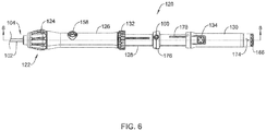
- FIG. 6 illustrates a top view of the handle assembly 120 of the delivery device 100.
- Figure 7 illustrates a bottom view of the handle assembly, approximately 180° from the view shown in Figure 6 .
- the handle assembly 120 may include one or more ports 158, 160, 162 for delivering fluids, such as, but not limited to, a contrast and/or flushing fluid to the cavity 142 of the device containment housing 108.
- the flush ports 158, 160, 162 may be in fluid communication with the lumens 150, 152, 154 of the outer, intermediate or inner tubular members 102, 110, 116, as desired.
- the flush port 158 may be in fluid communication with the lumen 150 of the outer tubular member 102
- the flush port 160 may be in fluid communication with the lumen 152 of the intermediate tubular member 110
- the flush port 162 may be in fluid communication with the lumen 154 of the inner tubular member 116.
- the handle assembly 120 may further include a tether lock 164.
- the tether lock 164 may be actuatable between a locked and an unlocked configuration to maintain the tether 112 in a desired orientation.
- the ends of the tether 112 may affixed to, secured to, or otherwise engage a tether cap 166 positioned at a proximal end of the third hub portion 130.
- the tether cap 166 may be removably secured to the third hub portion 130 to allow a clinician access to the ends of the tether 112. When the tether lock 164 is in the locked configuration, the tether cap 166 may not be removed from the third hub portion 130.
- the tether cap 166 may be removed and the ends of the tether 112 may be actuated.
- the tether 112 may be removed from the tether retention feature 36 of the IMD 10 by pulling on one of the ends until the opposite end has passed through the opening 38 such that the IMD 10 is free from the tether 112.
- the handle assembly 120 may also include visual markings, such as, but not limited to the markings illustrated at 170, 172, 174. These markings 170, 172, 174 may provide visual instructions or indications to the clinician.
- the marking shown at 170 may be positioned proximate the rotatable member 124 of the actuation mechanism 122 to indicate that the rotatable member 124 controls deflection of the outer tubular member 102 and/or to indicate which direction the distal section 106 will deflect when the rotatable member 124 of the actuation mechanism 122 is rotated in a given direction.
- the markings shown at 172 may provide an indication of whether the second locking mechanism 132 is in the unlocked and/or locked configuration.
- the markings shown at 174 may provide an indication of whether the tether lock 164 is in the unlocked and/or locked configuration.
- Figure 8 illustrates a cross-sectional view of the handle assembly 120 of the delivery device.
- the handle assembly 120 may include a first hub portion 126 attached to the proximal end section 104 of the outer tubular member 102, a second hub portion 128 attached to a proximal end section of the intermediate tubular member 110, and a third hub portion 130 attached to a proximal end section of the inner tubular member 116.
- Each of the first hub portion 126, the second hub portion 128, and the third hub portion 130 may be slidable and rotatable relative to each other such that the outer tubular member 102, intermediate tubular member 110, and inner tubular member 116 may be individually longitudinally actuated.
- the inner tubular member 116 may extend distally from a proximal end 117.
- the proximal end 117 of the inner tubular member 116 may be positioned within or adjacent to the tether lock 164.
- the tether lock 164 may include a port 162 which may be in fluid communication with a lumen 154 of the inner tubular member 116.
- the lumen 154 may extend from the proximal end 117 to the distal portion 118 for delivering fluids, such as, but not limited to, a contrast and/or flushing fluid to the cavity 142 of the device containment housing 108.
- the inner tubular member 116 may be coupled or affixed to the third hub portion 130 adjacent the proximal end 117 of the inner tubular member 116, although this is not required. In some cases, the inner tubular member 116 may be affixed to the third hub portion 130 at any longitudinal location desired. In some instances, a tether, such as tether 112, for securing the IMD 10 to the distal portion 118 of the inner tubular member 116 may be disposed within the lumen 154 and may exit the delivery device 100 through or adjacent to tether cap 166, although this is not required.
- the intermediate tubular member 110 may extend distally from a proximal end 111.
- the proximal end 111 of the intermediate tubular member 110 may be positioned within the second hub portion 128.
- the intermediate tubular member 110 may include a lumen 152 extending from the proximal end 111 to a distal end of the intermediate tubular member 110.
- the inner tubular member 116 may be slidably disposed within the lumen 152 of the intermediate tubular member 110.
- the intermediate tubular member 110 may be coupled or affixed to the second hub portion 128 adjacent the proximal end 111 of the intermediate tubular member 110, although this is not required.
- the intermediate tubular member 110 may be affixed to the second hub portion 128 at any longitudinal location desired.
- the outer tubular member 102 may extend distally from a proximal end 105.
- the proximal end 105 of the outer tubular member 102 may be positioned within the first hub portion 126.
- the outer tubular member 102 may include a lumen 150 extending from the proximal end 105 to a distal end 103 of the outer tubular member 102.
- the intermediate tubular member 110 may be longitudinally slidably disposed within the lumen 150 of the outer tubular member 102.
- the outer tubular member 102 may be coupled or affixed to the first hub portion 126 adjacent the proximal end 105 of the outer tubular member 102, although this is not required. In some cases, the outer tubular member 102 may be affixed to the first hub portion 126 at any longitudinal location desired.
- the first hub portion 126 may include a retaining ring 182 positioned adjacent to a proximal end of the first hub portion 126.
- the retaining ring 182 may be rotatable about a longitudinal axis of the handle assembly 120.
- the retaining ring 182 may include locking features configured to engage with other locking features of the locking mechanism 132. When the retaining ring 182 engages other features of the locking mechanism 132, longitudinal movement of the first hub portion 126 and the second hub portion 128 relative to one another may be prevented. Rotating the retaining ring 182 may disengage the retaining ring 182 from the other features of the locking mechanism 132.
- first hub portion 126 and the second hub portion 128 may allow for longitudinal movement of the first hub portion 126 and the second hub portion 128 relative to one another, as will be described in more detail below.
- second locking mechanism 132 is described as a rotating retaining ring 182
- other locking mechanisms capable of releasably securing first hub portion 126 and the second hub portion 128, and thus the outer tubular member 102 and the intermediate tubular member 110, may be used.
- the first locking mechanism 134 may include a depressible button 131.
- the depressible button 131 may include a first outwardly protruding portion 133 configured to engage a region of the third hub portion 130 and a second inwardly protruding portion 135 configured to engage a region of the second hub portion 128.
- the second protruding portion 135 may be disposed in and engage a groove or recess 178 formed in the second hub portion 128.
- the engagement of the first locking mechanism 134 may prevent or reduce relative movement of the second hub portion 128 and the third hub portion 130 when the first locking mechanism 134 is not actively actuated (e.g. depressed) by a clinician.
- a downward force 186 may be applied to the button 131.
- the force 186 may cause the first protruding portion 133 to lower and/or disengage from a surface of the third hub portion 130 and the second protruding portion 135 to raise and/or disengage from a surface of the second hub portion 128.
- This may allow the third hub portion 130 to be moved longitudinally (e.g., proximally and/or distally), as shown at 184, along a longitudinal axis of the handle assembly 120 relative to the second hub portion 128, as will be discussed in more detail below. Longitudinal actuation of the third hub portion 130 relative to the second hub portion 128 may result in a corresponding longitudinal actuation of the inner tubular member (and hence the IMD 10) relative to the intermediate tubular member 110 and the device containment housing 108.
- FIG. 8 illustrates the second protruding portion 135 disposed in the middle of the recess 178.
- the second protruding portion 135 may be positioned at the proximal end of the recess 178 to ensure the IMD 10 is fully disposed in the device containment housing 108.
- the first locking mechanism 134 is described as a depressible button 131, in some cases other locking mechanisms capable of releasably securing the second hub portion 128 and the third hub portion 130, and thus the intermediate tubular member 110 and the inner tubular member 116, may be used.
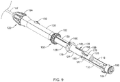
- Figure 9 illustrates a partial perspective view of the handle assembly 120 with portions of the third hub portion 130 removed to more clearly illustrate features of the second hub portion 128.
- a proximal portion 127 of the second hub portion 128 may include a groove or recess 178 formed therein.
- the groove 178 may extend from a proximal end 179 to a distal end 181.
- groove 178 may include a proximal portion 177 and a distal portion 183 which may be circumferentially offset from one another.
- a hard stop 180 may be provided at a region between the proximal end 179 and the distal end 181.
- the hard stop 180 may be a wall or other protrusion configured to engage the second protruding portion 135 of the first locking mechanism 134 such that in order to advance the second protruding portion 135 distally past the hard stop 180 from the proximal portion 177, the user rotates the third hub portion 130 to align the second protruding portion 135 with the distal portion 183 of the groove 178. This may allow the implantable device 10 to be incrementally deployed.
- the second protruding portion 135 may be disposed within the proximal portion 177 adjacent to the proximal end 179.
- the second protruding portion 135 may engage a surface of the second hub portion 128 to prevent and/or minimize relative movement of the second and third hub portions 128, 130 relative to one another.
- the groove 178 may also include an angled region 198 between the proximal portion 177 and the distal portion 183 positioned generally opposite the hard stop 180.
- the angled region 198 may guide the second protruding portion 135 from the distal portion183 of the groove 178 to the proximal portion 177 of the groove in a single fluid movement.
- the third hub portion 130 may be proximally retracted from the distal end 181 to the proximal end 179 relative to the second hub portion 128 in a single proximal movement, if so desired, without prohibiting travel of the second protruding portion 135 from the distal portion 183 to the proximal portion 177.
- a distal portion 129 of the second hub portion 128 may include a groove or recess 188 configured to receive a mating feature disposed on the first hub portion 126. This may allow the first hub portion 126 to be proximally retracted over the second hub portion 128, as will be discussed in more detail below.
- the proximal and distal portions 127, 129 of the second hub portion 128 may be separated by a gripping region 176 configured to provide a region for the clinician to hold.
- the delivery device 100 may be introduced into the vasculature through the femoral vein through a previously introduced guide catheter. This is just an example.
- the delivery device 100 may be introduced through any desired location and with or without the use of a guide catheter as desired.
- the delivery device 100 may be advanced through the vasculature to the desired treatment location, which, in the case of a leadless cardiac pacing device, may be a chamber of the heart.
- the clinician may use the actuation mechanism 122 may to deflect the distal section 106 of the outer tubular member 102 in a desired manner to facilitate advancement of the delivery device 100.
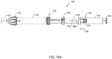
- the handle assembly 120 may be in a fully extended configuration, as shown in Figure 10A .
- the third hub portion 130 may be at its proximal-most location relative to the second hub portion 128 and the first hub portion 1 26 may be at its distal-most location relative to the second hub portion 128.
- the inner tubular member 116, intermediate tubular member 110, and the outer tubular member 102 may be oriented in the manner illustrated in Figure 5 .
- the delivery device 100 can be imaged using known techniques to ensure accurate placement of the IMD 10.
- the first stage of deploying the IMD 10 may enable activation of the fixation mechanism 24.
- the clinician may stabilize the first hub portion 126 relative to the patient and depress the button 131 of the first locking mechanism 134.
- the clinician may then slide the third hub portion 130 distally, as shown at 190, until the first locking mechanism 134 engages the hard stop 180 provided in the second hub portion 128 resulting in the handle assembly 120 configuration shown in Figure 10B .
- Distal actuation of the third hub portion 130 may also move the inner tubular member 116 distally by the same distance.
- the distal portion 118 may "push" against the proximal end 14 of the implantable device 10.
- the hooks 26 engage the heart tissue as shown in Figure 10C .
- the IMD 10 may be distally advanced out of the device containment housing 108 to deploy the hooks or tines 26 from the device containment housing 108 to engage the hooks or tines 26 in the heart tissue while the proximal portion of the IMD 10 remains within the device containment housing 108.
- the IMD 10 may be advanced distally in the range of 1 to 5 millimeters, although this is merely illustrative.
- the first locking mechanism 134 may prevent accidental or unintentional deployment of the IMD 10 as the button 131 must be actuated while advancing the third hub portion 130.
- the device containment housing 108 and the intermediate tubular member 110 may be desirable to advance the device containment housing 108 and the intermediate tubular member 110 without advancing the outer tubular member 102 (i.e., telescoping the intermediate tubular member 110). For example, this may facilitate advancement of the delivery device 100 within the heart or maintain the position of the device containment housing 108 once it is placed again the heart wall.
- the second locking mechanism 132 may be actuated to "unlock" the first hub portion 126 and the second hub portion 128.
- a rotating retaining ring 182 may be rotated, as shown at 194, to move the second locking mechanism 132 from a locked to an unlocked configuration.
- the clinician may distally advance 196 the second and third hub portions 128, 130 together to distally advance the device containment housing 108 as far as desired and/or needed.
- the actuation of the second and third hub portions 128, 130 may simultaneously move the intermediate tubular member 110 and the inner tubular member 116 as well. This may be done during advancement of the delivery device 100 through the vasculature, before initiating the first stage of deploying the IMD 10, and/or after the first stage of deploying the IMD 10 has been completed, as desired or needed.
- the tether 112 may be used to perform a tug test to determine if the IMD 10 is sufficiently engaged with the heart wall.
- the fixation of the IMD 10 e.g. how well the hooks 26 are secured to the heart tissue
- the fixation of the IMD 10 may be tested by gently tugging on the ends of the tether 112. If it is determined that the IMD 10 is sufficiently engaged with the heart wall, then the user may proceed to the second stage of deployment of the IMD 10 in which the remainder of the IMD 10 is expelled from the device containment housing 108.
- the user may use the tether to pull (retract) the IMD 10, including the tines or hooks 26, back into the device containment housing 108 to release the implantable device 10 from the heart wall.
- the IMD 10 may then be repositioned and the first stage of deployment repeated.
- the second stage of deploying the IMD 10 may proximally retract the device containment housing 108, and thus the intermediate tubular member 110, relative to the inner tubular member 116 to fully deploy the IMD 10.
- the intermediate tubular member 110, including the device containment housing 108, of the delivery device 100 can be proximally retracted.
- the clinician may first rotate the third hub portion 130, as shown at 192, such that the button 131 is aligned with the distal portion 183 of the groove 178.
- the clinician may then stabilize the third hub portion 130 relative to the patient and proximally retract the first and second hub portions 126, 128. It should be noted that while it is possible to distally actuate the third hub portion 130 at this point, this may cause additional and unnecessary forces to be applied to the heart wall. Further, such distal movement of the third hub portion 130 may move the inner tubular member 116 (and hence the implantable device 10) distally rather than proximally retracting the intermediate tubular member 110 and/or the outer tubular member 102. The first and second hub portions 126, 128 may be proximally retracted until the first locking mechanism 134 engages the distal end 181 of the groove 178, resulting in the handle assembly 120 configuration shown in Figure 10D . Such actuation of the first and second hub portions 126, 128 may fully deploy the implantable device 10 such that the IMD 10 is exterior of the device containment housing 108 and engaged with the heart wall, as shown in Figure 10E .
- the IMD 10 may still be affixed to the delivery device 100 through the tether 112. Once the clinician has verified the position of the IMD 10, the fixation of the IMD 10 and/or the electrical performance of the IMD 10, the tether 112 may be removed. In some instances, fixation of the IMD 10 (e.g. how well the hooks 26 are secured to the heart tissue) may be tested by gently tugging on the ends of the tether 112.
- the tether 112 may be removed by unlocking the tether lock 164, removing the tether cap 166, cutting the tether 112 at some location along its length, and pulling on one of the ends until the opposite end has passed through the opening 38 of the IMD 10 such that the IMD 10 is free from the tether 112.
- the tether 112 may be affixed to a portion of the tether cap 166 (e.g. creating a loop) such that the tether 112 must be cut to allow the IMD 10 to be freed from the tether 112.
- FIG. 12 provides a schematic illustration of a delivery and deployment device 200 which may, as will be appreciated, be considered as an example of the delivery device 100.
- the delivery and deployment device 200 includes a device containment housing 202 that is located at a distal end 204 of a shaft 206.
- a handle assembly 208 may be located at a proximal end 210 of the shaft 206.
- the device containment housing 202 may be considered as representing the device containment housing 108 discussed with respect to the previous Figures.
- the shaft 206 may be considered as representing the outer tubular member 102 discussed above and may include one or more inner tubular members (not visible in this schematic view).
- the handle assembly 208 may be considered as representing and/or including one or more of the distal hub portion 126, the intermediate hub portion 128 and the proximal hub portion 130.
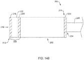
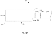
- the device containment housing 202 has a distal end 212 and a proximal end 214. In some cases, the distal end 212 of the device containment housing 202 may be open, and the device containment housing 202 may define a void 216 therein that may be configured to accommodate an implantable medical device (such as but not limited to the IMD 10).
- the device containment housing 202 includes a first position indicator 218 that is located at or near the distal end 212 of the device containment housing 202. In some cases, the device containment housing 202 includes a second position indicator 220 that is located proximally of the first position indicator 218. In some embodiments, a compressible region 222 may be located at least partially between the first position indicator 218 and the second position indicator 220. In some instances, the compressible region 222 may be entirely located between the first position indicator 218 and the second position indicator 220. In some cases, the compressible region 222 may not be entirely located between the first position indicator 218 and the second position indicator 220 and may, for example, extend proximally beyond the second position indicator 220.
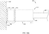
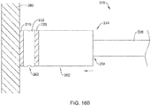
- the compressible region 222 may compress by an amount that is proportional or otherwise related to the applied force.
- a distance between the first position indicator 218 and the second position indicator 220 may change.
- the amount that the distance between the first position indicator 218 and the second position indicator 220 changes may be proportional or otherwise related to the applied force.
- the first position indicator 218 and the second position indicator 220 may be configured to be visible via an imaging process such as fluoroscopy, particularly as in some cases implantable devices such as the IMD 10 may be guided to the intended destination under fluoroscopy.
- the first position indicator 218 may be a first radiopaque marker band and the second position indicator 220 may be a second radiopaque marker band.
- the first position indicator 218 may be a first electrode and the second position indicator 220 may be a second electrode. In some cases, the first position indicator 218 and/or the second position indicator 220 may each independently be ring electrodes. It will be appreciated that as the distance between the first position indicator 218 and the second position indicator 220 changes, an impedance value between the first position indicator 218 and the second position indicator may change. Accordingly, the changing impedance value may be used to ascertain how much force has been applied to the distal end 212 of the device containment housing 202. In some cases, the device containment housing 202 may include a third electrode 224.
- the third electrode 224 is schematically illustrated as being located at the proximal end 214 of the device containment housing 202, it will be appreciated that in some cases the third electrode 224 may be located elsewhere on the device containment housing 202, be located on the shaft 206, or be absent. In some cases, when the a sufficient amount of force is applied, a first audible and/or tactile feedback may be provided to the user, and if too much force is applied, a second audible and/or tactile feedback may be provided to the user.
- the first position indicator 218 may not be a single electrode such as a ring electrode, but may instead be a plurality of electrodes.
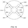
- Figure 13 is a schematic end view looking from the distal end and into the device containment housing 202.
- Figure 13 shows an implantable medical device (IMD) 230 disposed within the void 216 defined by the device containment housing 202.
- the IMD 230 may, for example, be considered as being representative of the IMD 10.
- the example IMD 230 includes a total of four anchoring talons 232, 234, 236 and 238, although in some cases the IMD 230 may have more than four anchoring talons or in some instances may have fewer than four anchoring talons, or may have a different fixation mechanism altogether.
- the device containment housing 202 may include a first electrode 240 that may be at least substantially aligned with the anchoring talon 232, a second electrode 242 that may be at least substantially aligned with the anchoring talon 234, a third electrode 244 that may be at least substantially aligned with the anchoring talon 236, and/or a fourth electrode 246 that may be at least substantially aligned with the anchoring talon 238.
- one or more of the electrodes 240, 242, 244, 246 may be used as the first position indicator 218, in combination with another electrode functioning as the second position indicator 220, to provide an indication of the force being applied to the distal end 212 of the device containment housing 202 as a result of the distal end 212 of the device containment housing 202 contacting tissue such as cardiac tissue.
- tissue such as cardiac tissue does not present a simple, planar surface. It may be useful to be able to determine which portion or portions of the distal end 212 of the device containment housing 202 may be in good tissue contact as this may provide an indication of how well one or more individual talons 232, 234, 236 and 238 may fixate within the tissue.
- the electrodes 240, 242, 244, 246 may individually be utilized, sometimes in combination with another electrode such as the electrode forming the second position indicator 220 or perhaps the third electrode 224, to determine if the aforementioned electrode 240, 242, 244, 246 is in contact with tissue, which may give an indication of whether the corresponding talon 232, 234, 236, 238 might be well-positioned to engage tissue when the IMD 230 is subsequently deployed. If not, a different location may be investigated, or the device containment housing 202 may be rotated before checking again. It is best to have all four talons 232, 234, 236, 238 properly engage tissue.
- Figures 14A-14C provide a closer view of the illustrative device containment housing 202.
- Figure 14A represents a starting point with respect to the first position indicator 218 and the second position indicator 220, such as may occur prior to the distal end 212 of the device containment housing 202 contacting tissue such as cardiac tissue.
- tissue such as cardiac tissue.
- the distance 252 is less than the distance 250 and the distance 252 is greater than zero.
- the distance 252 may, for example, correspond to a desired compression of the compressible region 222, thereby indicating an appropriate amount of force being applied by virtue of the distal end 212 of the device containment housing 202 contacting tissue such as cardiac tissue.
- Figure 14C illustrates what may happen if too much force has been applied.
- the second position indicator 220 has moved much closer to the first position indicator 218 and may actually be in contact with the first position indicator 218 and/or the compressible region 222 has reached its fully compressed state.
- the compressible region 222 may be designed such that when the second position indicator 220 is in the intermediate state shown in Figure 14B , an adequate yet safe force is being applied by the device containment housing to the contacting tissue.
- first position indicator 218 and the second position indicator 220 may not be disposed on the device containment housing 202, as shown in Figures 14A-C , but may instead be located on the shaft 206, at or near the distal end 204 of the shaft 206.
- Figures 15A-15C illustrate a changing distance between a first position indicator 318 and the second position indicator 320 when both are disposed on the shaft 206.
- Figure 15A represents a starting point with respect to the first position indicator 518 and the second position indicator 520, such as may occur prior to the distal end 212 of the device containment housing 202 contacting tissue such as cardiac tissue.
- FIG. 15B there is a distance 352 between the first position indicator 318 and the second position indicator 320. It will be appreciated that the distance 352 is less than the distance 350 and the distance 352 is greater than zero. In some cases, the distance 352 may, for example, correspond to a desired compression of the compressible region 322, thereby indicating an appropriate amount of force being applied by virtue of the distal end 212 of the device containment housing 202 contacting tissue such as cardiac tissue.
- Figure 15C illustrates what may happen if too much force has been applied. In Figure 15C , the second position indicator 320 has moved much closer to the first position indicator 318 and may actually be in contact with the first position indicator 318 and/or the compressible region 322 has reached its fully compressed state.
- Figure 16A illustrates the device containment housing 202 in position against tissue 360.
- the tissue 360 may be cardiac tissue such as a ventricular wall, but this is not required. This represents a starting point, much like that shown in Figure 14A , in which essentially no force has been applied to the device containment housing 202, as indicated by the distance 250 between the first position indicator 218 and the second position indicator 220.
- Figures 16B and 16C provide enlarged views of the device containment housing 202, showing several illustrative but non-limiting examples of how the compressible region 222 may compress during use.
- the compressible region 222 forms an accordion region 362 in which the side wall of the device containment housing 202 forms an undulating wave form.
- the compressible region 222 forms a bulged or billowed region 364 in which the side wall of the device containment housing 202 distends outwardly as a result of an applied force.
- the relative change in distance between the first position indicator 218 and the second position indicator 220 may provide an indication of how much force is being applied.
- the compressible region 222 may include a spring sometimes incorporated into a weave, may include a compressible material, and/or may otherwise be constructed to provide a predictable and appropriate compression force versus compression distance profile.
- the compressible region 222 may be considered a force sensor.
- the delivery and deployment device 200 may include one or more force sensors that may, for example, provide an indication of a force being applied to the IMD 10 during deployment of the IMD 10.
- one or more force sensors that provide an indication of forces (compressive or tensile) applied to the IMD 10 during or after deployment of the IMD 10 may be used in addition to the previously described first and second position indicators that indicate forces applied to the device containment housing 108.
- one or more force sensors that provide an indication of forces (compressive or tensile) applied to the IMD 10 during or after deployment of the IMD 10 may be used instead of measuring or otherwise indicating forces applied to the device containment housing 108.
- the IMD 10 may be implanted using an implantation structure lacking the device containment housing 108.
- the delivery and deployment device 200 may include one or more force sensors that may, for example, provide an indication of a tensile force being applied to the IMD 10 during a post-deployment tug test.
- Figures 17-19 are similar to Figure 5 but provide illustrative but non-limiting examples of where such force sensors may be disposed within or near the device containment housing 108.
- a force sensor 370 may be seen attached or otherwise disposed on the distal portion 118 of the inner tubular member 116 which, as discussed, may be used to engage and push the IMD 10 out of the device containment housing 108 during deployment of the IMD 10.
- Figure 18 is similar, but illustrates a force sensor 372 that is attached to or otherwise disposed on the inner tubular member 116.
- the force sensors 370 and 372 may be any desired type of force sensor that may provide a signal representative of the force being applied to the IMD 10.
- Figure 19 provides an illustrative but non-limiting example of a force sensor 374 that may be attached to, or form a portion of, the tether 112.
- the force sensor 374 may, for example, be a strain gauge and thus may provide an indication of the force applied to the IMD 10 via the tether 112 during a tug test after deployment, such as that illustrated in Figure 10E .
- the strain gauge may be a fiber optic or piezo type strain sensor.
- Figure 20 provides an example of a force sensor 376 that may be disposed within the device containment housing 108.
- the force sensor 376 may be a pressure sensor, and may provide an indication of whether fluid that may be pumped into the device containment housing 108 remains in the device containment housing, indicating a good contact between the tip 140 of the device containment housing 108 and the adjoining tissue, or if the fluid has leaked out, indicating poor contact.
- the force sensor 376 may be positioned elsewhere along a fluid path to the device containment housing 108 and could even be disposed within the handle assembly 120.
- force sensor 376 may be a strain sensor or the like attached to or incorporated into the device containment housing wall. Such strain sensor may sense the axial, compressive and/or bending strain in the wall of the device containment housing, which will be related to the force applied to the cardiac tissue via the device containment housing. In some cases, the strain sensor may be a fiber optic or piezo type sensor. It will be appreciated that while not illustrated, the force sensors 370, 372, 374, 376 may include additional structure for communicating force values to an outside display, for example.
- a delivery device may utilize two or more of the force sensors 370, 372, 374, 376 in combination.
- a delivery device may include the force sensor 370 or the force sensor 372 in combination with the force sensor 374.
- a delivery device may, for example, include the force sensor 370 or the force sensor 374 in combination with the force sensor 376.
- a delivery device may include the force sensor 374 and the force sensor 376.
- the materials that can be used for the various components of the delivery devices, such as delivery device 100 (and/or other delivery structures disclosed herein) and the various members disclosed herein may include those commonly associated with medical devices.
- delivery device 100 and the delivery and deployment device 200 and components thereof.
- this is not intended to limit the devices and methods described herein, as the discussion may be applied to other similar delivery systems and/or components of delivery systems or devices disclosed herein.
- the delivery device 100 and/or the deployment and delivery device 200, or components thereof, may be made from a metal, metal alloy, polymer (some examples of which are disclosed below), a metal-polymer composite, ceramics, combinations thereof, and the like, or other suitable material.
- suitable polymers may include polytetrafluoroethylene (PTFE), ethylene tetrafluoroethylene (ETFE), fluorinated ethylene propylene (FEP), polyoxymethylene (POM, for example, DELRIN® available from DuPont), polyether block ester, polyurethane (for example, Polyurethane 85A), polypropylene (PP), polyvinylchloride (PVC), polyether-ester (for example, ARNITEL® available from DSM Engineering Plastics), ether or ester based copolymers (for example, butylene/poly(alkylene ether) phthalate and/or other polyester elastomers such as HYTREL® available from DuPont), polyamide (for example, DURETHAN® available from Bayer or CRISTAMID® available from Elf Atochem), elastomeric polyamides, block polyamide/ethers, polyether block amide (PEBA, for example available under the trade name PEBAX®), ethylene vinyl acetate
- suitable metals and metal alloys include stainless steel, such as 304V, 304L, and 316LV stainless steel; mild steel; nickel-titanium alloy such as linear-elastic and/or super-elastic nitinol; other nickel alloys such as nickel-chromium-molybdenum alloys (e.g., UNS: N06625 such as INCONEL® 625, UNS: N06022 such as HASTELLOY® C-22®, UNS: N10276 such as HASTELLOY® C276®, other HASTELLOY® alloys, and the like), nickel-copper alloys (e.g., UNS: N04400 such as MONEL® 400, NICKELVAC® 400, NICORROS® 400, and the like), nickel-cobalt-chromium-molybdenum alloys (e.g., UNS: R30035 such as MP35-N® and the like), nickel-molybdenum alloys (e.g.,
- portions or all of the delivery device 100 and/or the deployment and delivery device 200, or components thereof may be doped with, made of, or otherwise include a radiopaque material.
- Radiopaque materials are understood to be materials capable of producing a relatively bright image on a fluoroscopy screen or another imaging technique during a medical procedure. This relatively bright image aids the user of the delivery device 100 in determining its location.
- Some examples of radiopaque materials can include, but are not limited to, gold, platinum, palladium, tantalum, tungsten alloy, polymer material loaded with a radiopaque filler, and the like. Additionally, other radiopaque marker bands and/or coils may also be incorporated into the design of the delivery device 100 and/or the deployment and delivery device 200, or components thereof, to achieve the same result.
Claims (9)
- Dispositif de pose et de déploiement (100, 200) configuré pour poser un dispositif médical implantable (IMD) (10, 230) au niveau d'une chambre du cœur d'un patient et pour déployer l'IMD (10, 230) à l'intérieur, le dispositif de pose et de déploiement (100, 200) comprenant :un assemblage de manche (120, 208) ;un arbre (206) qui s'étend de façon distale depuis l'assemblage de manche (120, 208), l'arbre (206) incluant une région distale ;un boîtier de contenance de dispositif (12, 108, 202) qui est couplé à la région distale de l'arbre (206) et qui s'étend de façon distale depuis celle-ci, le boîtier de contenance de dispositif (12, 108, 202) étant configuré de manière à ce qu'il loge l'IMD (10, 230) en son sein ;au moins un élément constitutif pris parmi l'arbre (206) et le boîtier de contenance de dispositif (12, 108, 202) incluant une région compressible (222. 322) qui est configurée de manière à ce qu'elle soit comprimée selon une ampleur de compression qui est rapportée à une force appliquée ;un premier indicateur de position (218, 318, 518) et un second indicateur de position (220, 320, 520), dans lequel au moins une partie de la région compressible (222. 322) est située entre le premier indicateur de position (218, 318, 518) et le second indicateur de position (220, 320, 520) ; et dans lequel :
une force qui est appliquée sur le boîtier de contenance de dispositif a pour effet que la région compressible est comprimée selon une ampleur de compression qui est rapportée à la force appliquée, ce qui génère une modification de la distance entre le premier indicateur de position (218, 318, 518) et le second indicateur de position (220, 320, 520), laquelle modification de distance constitue une indication de la force appliquée. - Dispositif de pose et de déploiement (100, 200) selon la revendication 1, dans lequel le boîtier de contenance de dispositif (12, 108, 202) inclut la région compressible (222. 322).
- Dispositif de pose et de déploiement (100, 200) selon l'une quelconque des revendications 1 et 2, dans lequel le premier indicateur de position (218, 318, 518) comprend une première bande de marqueur radio-opaque et le second indicateur de position (220, 320, 520) comprend une seconde bande de marqueur radio-opaque, et la modification de la distance entre le premier indicateur de position (218, 318, 518) et le second indicateur de position (220, 320, 520) est visible via une fluoroscopie.
- Dispositif de pose et de déploiement (100, 200) selon l'une quelconque des revendications 1 et 2, dans lequel le premier indicateur de position (218, 318, 518) comprend une première électrode (20) et le second indicateur de position (220, 320, 520) comprend une seconde électrode (22), et la modification de la distance entre la première électrode (20) et la seconde électrode (22) est indiquée via une modification de l'impédance entre la première électrode (20) et la seconde électrode (22).
- Dispositif de pose et de déploiement (100, 200) selon la revendication 4, dans lequel la première électrode (20) comprend une électrode en anneau.
- Dispositif de pose et de déploiement (100, 200) selon la revendication 4, dans lequel la première électrode (20) comprend une électrode d'une pluralité d'électrodes qui sont disposées radialement autour d'une extrémité distale (16) du boîtier de contenance de dispositif (12, 108, 202) et qui peuvent être alignées avec chacun d'une pluralité de talons de l'IMD (10, 230).
- Dispositif de pose et de déploiement (100, 200) selon la revendication 4, dans lequel la seconde électrode (22) comprend une électrode en anneau.
- Dispositif de pose et de déploiement (100, 200) selon l'une quelconque des revendications 1 à 7, comprenant en outre un capteur de force (370, 372, 374, 376) qui est agencé et configuré de manière à ce qu'il fournisse une indication d'une force qui est appliquée sur l'IMD (10, 230) pendant son implantation.
- Dispositif de pose et de déploiement (100, 200) selon l'une quelconque des revendications 1 à 8, comprenant en outre un capteur de force (370, 372, 374, 376) qui est agencé et configuré de manière à ce qu'il fournisse une indication d'une force qui est appliquée sur un IMD (10, 230) pendant un test de tirage après le déploiement de l'IMD (10, 230).
Applications Claiming Priority (2)
| Application Number | Priority Date | Filing Date | Title |
|---|---|---|---|
| US201662291330P | 2016-02-04 | 2016-02-04 | |
| PCT/US2017/016212 WO2017136548A1 (fr) | 2016-02-04 | 2017-02-02 | Système de pose avec capteur de force pour dispositif cardiaque sans fil |
Publications (2)
| Publication Number | Publication Date |
|---|---|
| EP3411113A1 EP3411113A1 (fr) | 2018-12-12 |
| EP3411113B1 true EP3411113B1 (fr) | 2019-11-27 |
Family
ID=58108728
Family Applications (1)
| Application Number | Title | Priority Date | Filing Date |
|---|---|---|---|
| EP17706916.8A Active EP3411113B1 (fr) | 2016-02-04 | 2017-02-02 | Système de pose avec capteur de force pour dispositif cardiaque sans fil |
Country Status (4)
| Country | Link |
|---|---|
| US (1) | US10350423B2 (fr) |
| EP (1) | EP3411113B1 (fr) |
| CN (1) | CN109069840B (fr) |
| WO (1) | WO2017136548A1 (fr) |
Families Citing this family (18)
| Publication number | Priority date | Publication date | Assignee | Title |
|---|---|---|---|---|
| US11198013B2 (en) | 2016-11-21 | 2021-12-14 | Cardiac Pacemakers, Inc. | Catheter and leadless cardiac devices including electrical pathway barrier |
| US10905465B2 (en) | 2016-11-21 | 2021-02-02 | Cardiac Pacemakers, Inc. | Delivery devices and wall apposition sensing |
| CN110167632B (zh) | 2016-12-27 | 2023-06-09 | 心脏起搏器股份公司 | 具有导电通路的无引线递送导管 |
| CN110114114B (zh) | 2016-12-27 | 2023-05-02 | 心脏起搏器股份公司 | 用于无引线心脏装置的递送装置和方法 |
| US10485981B2 (en) | 2016-12-27 | 2019-11-26 | Cardiac Pacemakers, Inc. | Fixation methods for leadless cardiac devices |
| US10806931B2 (en) | 2016-12-27 | 2020-10-20 | Cardiac Pacemakers, Inc. | Delivery devices and methods for leadless cardiac devices |
| WO2018140597A2 (fr) | 2017-01-26 | 2018-08-02 | Cardiac Pacemakers, Inc. | Dispositifs et procédés de pose pour dispositifs cardiaques sans fil |
| EP3592418B1 (fr) | 2017-03-10 | 2023-08-23 | Cardiac Pacemakers, Inc. | Fixation pour dispositifs cardiaques sans fil |
| US10737092B2 (en) | 2017-03-30 | 2020-08-11 | Cardiac Pacemakers, Inc. | Delivery devices and methods for leadless cardiac devices |
| US11577085B2 (en) | 2017-08-03 | 2023-02-14 | Cardiac Pacemakers, Inc. | Delivery devices and methods for leadless cardiac devices |
| US11197996B2 (en) * | 2018-03-28 | 2021-12-14 | Medtronic, Inc. | Delivery device for delivery of implantable or insertable medical devices |
| US10874850B2 (en) * | 2018-09-28 | 2020-12-29 | Medtronic, Inc. | Impedance-based verification for delivery of implantable medical devices |
| WO2020205397A1 (fr) | 2019-03-29 | 2020-10-08 | Cardiac Pacemakers, Inc. | Systèmes et procédés de traitement d'arythmies cardiaques |
| WO2020205401A1 (fr) | 2019-03-29 | 2020-10-08 | Cardiac Pacemakers, Inc. | Systèmes et procédés de traitement d'arythmies cardiaques |
| US11331475B2 (en) | 2019-05-07 | 2022-05-17 | Medtronic, Inc. | Tether assemblies for medical device delivery systems |
| US11571582B2 (en) | 2019-09-11 | 2023-02-07 | Cardiac Pacemakers, Inc. | Tools and systems for implanting and/or retrieving a leadless cardiac pacing device with helix fixation |
| WO2021050679A1 (fr) | 2019-09-11 | 2021-03-18 | Cardiac Pacemakers, Inc. | Outils et systèmes d'implantation et/ou de récupération d'un dispositif de stimulation cardiaque sans fil à fixation hélicoïdale |
| CN117339108B (zh) * | 2023-12-04 | 2024-02-13 | 山东瑞安泰医疗技术有限公司 | 一种可降低起搏阈值的无导线心脏起搏器系统 |
Family Cites Families (1080)
| Publication number | Priority date | Publication date | Assignee | Title |
|---|---|---|---|---|
| US2959056A (en) | 1958-02-10 | 1960-11-08 | Gulton Ind Inc | Catheter pressure gauge |
| US3943936A (en) | 1970-09-21 | 1976-03-16 | Rasor Associates, Inc. | Self powered pacers and stimulators |
| USRE30366E (en) | 1970-09-21 | 1980-08-12 | Rasor Associates, Inc. | Organ stimulator |
| US3835864A (en) | 1970-09-21 | 1974-09-17 | Rasor Ass Inc | Intra-cardiac stimulator |
| US4151513A (en) | 1975-03-06 | 1979-04-24 | Medtronic, Inc. | Apparatus for sensing and transmitting a pacemaker's stimulating pulse |
| US4256115A (en) | 1976-12-20 | 1981-03-17 | American Technology, Inc. | Leadless cardiac pacer |
| US4157720A (en) | 1977-09-16 | 1979-06-12 | Greatbatch W | Cardiac pacemaker |
| JPS5921495B2 (ja) | 1977-12-15 | 1984-05-21 | 株式会社豊田中央研究所 | 細管型圧力計 |
| DE2805681C2 (de) | 1978-02-10 | 1979-11-22 | Siemens Ag, 1000 Berlin Und 8000 Muenchen | Schaltungsanordnung zur Unterdrückung von Störsignalen in einem Nutzsignal |
| US4142530A (en) | 1978-03-06 | 1979-03-06 | Vitatron Medical B. V. | Epicardial lead |
| US4250884A (en) | 1978-11-06 | 1981-02-17 | Medtronic, Inc. | Apparatus for and method of programming the minimum energy threshold for pacing pulses to be applied to a patient's heart |
| US4476868A (en) | 1978-11-06 | 1984-10-16 | Medtronic, Inc. | Body stimulator output circuit |
| US4263919A (en) | 1979-10-12 | 1981-04-28 | Levin Kenneth M | Heartbeat detection and artifact discrimination method and apparatus |
| US4440173A (en) | 1979-11-08 | 1984-04-03 | Medtronic | Programmable body stimulation system |
| US4310000A (en) | 1980-01-23 | 1982-01-12 | Medtronic, Inc. | Implantable pulse generator having separate passive sensing reference electrode |
| US4312354A (en) | 1980-02-04 | 1982-01-26 | Arco Medical Products Company | Pacemaker with circuit for pulse width modulating stimulus pulses in accordance with programmed parameter control states |
| US4365639A (en) | 1980-02-07 | 1982-12-28 | Applied Cardiac Electrophysiology | Catheter, cardiac pacemaker and method of pacing |
| US4357946A (en) | 1980-03-24 | 1982-11-09 | Medtronic, Inc. | Epicardial pacing lead with stylet controlled helical fixation screw |
| US4323081A (en) | 1980-06-30 | 1982-04-06 | Medtronic, Inc. | Pacing lead |
| US4469091A (en) | 1980-08-28 | 1984-09-04 | Slanetz Jr Charles A | Tactile control device for a remote sensing device |
| US4556063A (en) | 1980-10-07 | 1985-12-03 | Medtronic, Inc. | Telemetry system for a medical device |
| US4630611A (en) | 1981-02-02 | 1986-12-23 | Medtronic, Inc. | Orthogonally-sensing lead |
| US4522208A (en) | 1981-04-16 | 1985-06-11 | Cardiofrance Compagnie Francaise D'electrocardiologie | Method for determining parameter values of an implanted programmable pacemaker |
| US4754753A (en) | 1981-05-12 | 1988-07-05 | Medtronic, Inc. | System for sensing electrical depolarization wave signals and their direction |
| US4793353A (en) | 1981-06-30 | 1988-12-27 | Borkan William N | Non-invasive multiprogrammable tissue stimulator and method |
| PL133646B1 (en) | 1981-10-22 | 1985-06-29 | Os Bad Rozwojowy Tech Medyc | Non-invasive method of measuring activation of hearth stimuli conducting system between successive stimulations |
| US4562841A (en) | 1982-08-05 | 1986-01-07 | Cardiac Pacemakers, Inc. | Programmable multi-mode cardiac pacemaker |
| US4593955A (en) | 1983-06-14 | 1986-06-10 | Robert Bosch Gmbh | Yaw-compensated vehicle anti-skid system |
| US4537200A (en) | 1983-07-07 | 1985-08-27 | The Board Of Trustees Of The Leland Stanford Junior University | ECG enhancement by adaptive cancellation of electrosurgical interference |
| US4635639A (en) | 1985-01-08 | 1987-01-13 | Physio-Control Corporation | Modular physiological instrument |
| US4712554A (en) | 1985-04-08 | 1987-12-15 | Baylor College Of Medicine | Electronic system to distinguish between sinus and nonsinus atrial depolarizations which do not stimulate ventricular depolarizations in response to nonsinus atrial depolarizations |
| US4729376A (en) | 1985-05-28 | 1988-03-08 | Cordis Corporation | Cardiac pacer and method providing means for periodically determining capture threshold and adjusting pulse output level accordingly |
| US4674508A (en) | 1985-05-28 | 1987-06-23 | Cordis Corporation | Low-power consumption cardiac pacer based on automatic verification of evoked contractions |
| DE3688070T2 (de) | 1985-12-11 | 1993-06-24 | Telectronics Nv | Apparat zur herzstimulation mit erfassung von hervorgerufenen herzpotentialen. |
| US4759366A (en) | 1986-03-19 | 1988-07-26 | Telectronics N.V. | Rate responsive pacing using the ventricular gradient |
| US4776338A (en) | 1986-06-16 | 1988-10-11 | Siemens Aktiengesellschaft | Cardiac pacer for pacing a human heart and pacing method |
| IT1214738B (it) | 1986-11-11 | 1990-01-18 | Sbm Soc Brevetti Medicina | Perfezionamento negli impianti di stimolazione cardiaca mediante pacemaker |
| US4887609A (en) | 1987-05-13 | 1989-12-19 | The Methodist Hospital System | Apparatus and method for filtering electrocardiograph signals |
| US4787389A (en) | 1987-07-16 | 1988-11-29 | Tnc Medical Devices Pte. Ltd. | Using an implantable antitachycardia defibrillator circuit |
| US4819662A (en) | 1987-10-26 | 1989-04-11 | Cardiac Pacemakers, Inc. | Cardiac electrode with drug delivery capabilities |
| US4886064A (en) | 1987-11-25 | 1989-12-12 | Siemens Aktiengesellschaft | Body activity controlled heart pacer |
| US5078134A (en) | 1988-04-25 | 1992-01-07 | Lifecor, Inc. | Portable device for sensing cardiac function and automatically delivering electrical therapy |
| DE3831809A1 (de) | 1988-09-19 | 1990-03-22 | Funke Hermann | Zur mindestens teilweisen implantation im lebenden koerper bestimmtes geraet |
| US4928688A (en) | 1989-01-23 | 1990-05-29 | Mieczyslaw Mirowski | Method and apparatus for treating hemodynamic disfunction |
| US5040534A (en) | 1989-01-25 | 1991-08-20 | Siemens-Pacesetter, Inc. | Microprocessor controlled rate-responsive pacemaker having automatic rate response threshold adjustment |
| US4989602A (en) | 1989-04-12 | 1991-02-05 | Siemens-Pacesetter, Inc. | Programmable automatic implantable cardioverter/defibrillator and pacemaker system |
| US4987897A (en) | 1989-09-18 | 1991-01-29 | Medtronic, Inc. | Body bus medical device communication system |
| US4967746A (en) | 1989-10-23 | 1990-11-06 | Intermedics, Inc. | Dual chamber pacemaker with adjustable blanking and V-A extension |
| JPH0659319B2 (ja) | 1989-11-17 | 1994-08-10 | 三洋電機株式会社 | ワイヤレス低周波治療器 |
| US5111812A (en) | 1990-01-23 | 1992-05-12 | Cardiac Pacemakers, Inc. | Defilbrillation electrode having smooth current distribution |
| US5058581A (en) | 1990-02-20 | 1991-10-22 | Siemens-Pacesetter, Inc. | Telemetry apparatus and method for implantable tissue stimulator |
| US5036849A (en) | 1990-04-04 | 1991-08-06 | Cardiac Pacemakers, Inc. | Variable rate cardiac pacer |
| US5284136A (en) | 1990-04-04 | 1994-02-08 | Cardiac Pacemakers, Inc. | Dual indifferent electrode pacemaker |
| US5133353A (en) | 1990-04-25 | 1992-07-28 | Cardiac Pacemakers, Inc. | Implantable intravenous cardiac stimulation system with pulse generator housing serving as optional additional electrode |
| US5203348A (en) | 1990-06-06 | 1993-04-20 | Cardiac Pacemakers, Inc. | Subcutaneous defibrillation electrodes |
| US5241961A (en) | 1990-07-13 | 1993-09-07 | Cook Pacemaker Corporation | Synchronous telemetry receiver and receiving method for an implantable medical device |
| US5113869A (en) | 1990-08-21 | 1992-05-19 | Telectronics Pacing Systems, Inc. | Implantable ambulatory electrocardiogram monitor |
| US5144950A (en) | 1990-08-30 | 1992-09-08 | Vitatron Medical B.V. | Rate controlled pacemaker system using ar interval for rate control |
| US5127401A (en) | 1990-11-09 | 1992-07-07 | Medtronic, Inc. | Method of and apparatus for multi-vector pacing artifact detection |
| US5117824A (en) | 1990-11-14 | 1992-06-02 | Medtronic, Inc. | Apparatus for monitoring electrical physiologic signals |
| US5170784A (en) | 1990-11-27 | 1992-12-15 | Ceon Ramon | Leadless magnetic cardiac pacemaker |
| US5179945A (en) | 1991-01-17 | 1993-01-19 | Cardiac Pacemakers, Inc. | Defibrillation/cardioversion system with multiple evaluation of heart condition prior to shock delivery |
| JPH05172154A (ja) | 1991-03-15 | 1993-07-09 | Yoshinori Miyake | 作業性と可撓性に優れた軸材の連結機構 |
| AU654552B2 (en) | 1991-04-05 | 1994-11-10 | Medtronic, Inc. | Subcutaneous multi-electrode sensing system |
| US5383915A (en) | 1991-04-10 | 1995-01-24 | Angeion Corporation | Wireless programmer/repeater system for an implanted medical device |
| US5674259A (en) | 1992-10-20 | 1997-10-07 | Gray; Noel Desmond | Multi-focal leadless apical cardiac pacemaker |
| US6144879A (en) | 1991-05-17 | 2000-11-07 | Gray; Noel Desmond | Heart pacemaker |
| US5954757A (en) | 1991-05-17 | 1999-09-21 | Gray; Noel Desmond | Heart pacemaker |
| US6044300A (en) | 1991-05-17 | 2000-03-28 | Gray; Noel Desmond | Heart pacemaker |
| US5243977A (en) | 1991-06-26 | 1993-09-14 | Trabucco Hector O | Pacemaker |
| US5259387A (en) | 1991-09-09 | 1993-11-09 | Quinton Instrument Company | ECG muscle artifact filter system |
| US5269326A (en) | 1991-10-24 | 1993-12-14 | Georgetown University | Method for transvenously accessing the pericardial space via the right auricle for medical procedures |
| WO1993008756A1 (fr) | 1991-11-08 | 1993-05-13 | Ep Technologies, Inc. | Systeme d'ablation a haute frequence a detection de puissance sensible a la phase |
| US5312439A (en) | 1991-12-12 | 1994-05-17 | Loeb Gerald E | Implantable device having an electrolytic storage electrode |
| US5193539A (en) | 1991-12-18 | 1993-03-16 | Alfred E. Mann Foundation For Scientific Research | Implantable microstimulator |
| US5193540A (en) | 1991-12-18 | 1993-03-16 | Alfred E. Mann Foundation For Scientific Research | Structure and method of manufacture of an implantable microstimulator |
| US5313953A (en) | 1992-01-14 | 1994-05-24 | Incontrol, Inc. | Implantable cardiac patient monitor |
| US5411525A (en) | 1992-01-30 | 1995-05-02 | Cardiac Pacemakers, Inc. | Dual capacitor biphasic defibrillator waveform generator employing selective connection of capacitors for each phase |
| EP0553864B1 (fr) | 1992-01-30 | 1999-10-27 | Cardiac Pacemakers, Inc. | Générateur de formes d'ondes pour la défibrillation pour la génération de formes d'ondes de longue durée |
| US5301677A (en) | 1992-02-06 | 1994-04-12 | Cardiac Pacemakers, Inc. | Arrhythmia detector using delta modulated turning point morphology of the ECG wave |
| US5305760A (en) | 1992-02-07 | 1994-04-26 | Interflo Medical Inc. | Method for rejecting electrical interference from physiological measurements |
| JPH05245215A (ja) | 1992-03-03 | 1993-09-24 | Terumo Corp | 心臓ペースメーカ |
| US5370667A (en) | 1992-04-03 | 1994-12-06 | Intermedics, Inc. | Device and method for automatically adjusting tachycardia recognition criteria based on detected parameter |
| US5342404A (en) | 1992-04-03 | 1994-08-30 | Intermedics, Inc. | Implantable medical interventional device |
| US5255679A (en) | 1992-06-02 | 1993-10-26 | Cardiac Pathways Corporation | Endocardial catheter for mapping and/or ablation with an expandable basket structure having means for providing selective reinforcement and pressure sensing mechanism for use therewith, and method |
| US5341807A (en) | 1992-06-30 | 1994-08-30 | American Cardiac Ablation Co., Inc. | Ablation catheter positioning system |
| US5300107A (en) | 1992-10-22 | 1994-04-05 | Medtronic, Inc. | Universal tined myocardial pacing lead |
| US5334222A (en) | 1992-11-03 | 1994-08-02 | Cardiac Pacemakers, Inc. | Cardiac stimulating apparatus and method for heart failure therapy |
| US5342408A (en) | 1993-01-07 | 1994-08-30 | Incontrol, Inc. | Telemetry system for an implantable cardiac device |
| US5318597A (en) | 1993-03-15 | 1994-06-07 | Cardiac Pacemakers, Inc. | Rate adaptive cardiac rhythm management device control algorithm using trans-thoracic ventilation |
| US5404877A (en) | 1993-06-04 | 1995-04-11 | Telectronics Pacing Systems, Inc. | Leadless implantable sensor assembly and a cardiac emergency warning alarm |
| US5350411A (en) | 1993-06-28 | 1994-09-27 | Medtronic, Inc. | Pacemaker telemetry system |
| SE9302357D0 (sv) * | 1993-07-07 | 1993-07-07 | Siemens-Elema Ab | Tryck- och hjaertroerelsesensor vid hjaertstimulatorer |
| US5468254A (en) | 1993-07-26 | 1995-11-21 | Cardiac Pacemakers, Inc. | Method and apparatus for defibrillation using a multiphasic truncated exponential waveform |
| WO1995005212A2 (fr) | 1993-08-11 | 1995-02-23 | Electro-Catheter Corporation | Electrode d'ablation amelioree |
| US5396887A (en) | 1993-09-23 | 1995-03-14 | Cardiac Pathways Corporation | Apparatus and method for detecting contact pressure |
| US5372606A (en) | 1993-10-07 | 1994-12-13 | Cardiac Pacemakers, Inc. | Method and apparatus for generating adaptive n-phasic defibrillation waveforms |
| US5376106A (en) | 1993-10-18 | 1994-12-27 | Cardiac Pacemakers, Inc. | Multi-sensor blending in a rate responsive cardiac pacemaker |
| WO1995010978A1 (fr) | 1993-10-19 | 1995-04-27 | Ep Technologies, Inc. | Dispositif d'ablation de tissus par electrodes segmentees |
| US5456691A (en) | 1993-11-12 | 1995-10-10 | Pacesetter, Inc. | Programming system having multiple program modules |
| US5411031A (en) | 1993-11-24 | 1995-05-02 | Incontrol, Inc. | Implantable cardiac patient monitor |
| US5447529A (en) | 1994-01-28 | 1995-09-05 | Philadelphia Heart Institute | Method of using endocardial impedance for determining electrode-tissue contact, appropriate sites for arrhythmia ablation and tissue heating during ablation |
| US6077236A (en) | 1994-06-07 | 2000-06-20 | Cunningham; David | Apparatus for monitoring cardiac contractility |
| US5466246A (en) | 1994-07-29 | 1995-11-14 | Pacesetter, Inc. | Telemetry receiver for implantable device, incorporating digital signal processing |
| US5522866A (en) | 1994-11-01 | 1996-06-04 | Intermedics, Inc. | Method and apparatus for improving the resolution of pulse position modulated communications between an implantable medical device and an external medical device |
| US5540727A (en) | 1994-11-15 | 1996-07-30 | Cardiac Pacemakers, Inc. | Method and apparatus to automatically optimize the pacing mode and pacing cycle parameters of a dual chamber pacemaker |
| US5545186A (en) | 1995-03-30 | 1996-08-13 | Medtronic, Inc. | Prioritized rule based method and apparatus for diagnosis and treatment of arrhythmias |
| WO1996034567A1 (fr) | 1995-05-02 | 1996-11-07 | Heart Rhythm Technologies, Inc. | Systeme permettant de commander l'energie appliquee a un patient en vue d'une ablation |
| JP4074661B2 (ja) | 1995-05-08 | 2008-04-09 | マサチューセッツ・インスティテュート・オブ・テクノロジー | 信号伝送媒体として人体を用いた非接触検知及び信号システム |
| US5791350A (en) | 1995-06-07 | 1998-08-11 | Morton; John Y. | Device and method for measuring force systems |
| US5827216A (en) | 1995-06-07 | 1998-10-27 | Cormedics Corp. | Method and apparatus for accessing the pericardial space |
| US5697925A (en) | 1995-06-09 | 1997-12-16 | Engineering & Research Associates, Inc. | Apparatus and method for thermal ablation |
| US6113592A (en) | 1995-06-09 | 2000-09-05 | Engineering & Research Associates, Inc. | Apparatus and method for controlling ablation depth |
| US5868737A (en) | 1995-06-09 | 1999-02-09 | Engineering Research & Associates, Inc. | Apparatus and method for determining ablation |
| US6322558B1 (en) | 1995-06-09 | 2001-11-27 | Engineering & Research Associates, Inc. | Apparatus and method for predicting ablation depth |
| US5752976A (en) | 1995-06-23 | 1998-05-19 | Medtronic, Inc. | World wide patient location and data telemetry system for implantable medical devices |
| US6083248A (en) | 1995-06-23 | 2000-07-04 | Medtronic, Inc. | World wide patient location and data telemetry system for implantable medical devices |
| US5842977A (en) | 1995-07-24 | 1998-12-01 | The Johns Hopkins University | Multi-channel pill with integrated optical interface |
| US5759199A (en) | 1995-08-02 | 1998-06-02 | Pacesetter, Inc. | System and method for ambulatory monitoring and programming of an implantable medical device |
| US5620466A (en) | 1995-08-14 | 1997-04-15 | Cardiac Pacemakers, Inc. | Digital AGC using separate gain control and threshold templating |
| US5662688A (en) | 1995-08-14 | 1997-09-02 | Cardiac Pacemakers, Inc. | Slow gain control |
| US5706823A (en) | 1995-08-18 | 1998-01-13 | Quinton Instrument Company | Electrophysiology filtering system |
| US5709215A (en) | 1995-09-06 | 1998-01-20 | Angeion Corporation | R-wave detection method for implantable cardioverter defibrillators |
| US5720770A (en) | 1995-10-06 | 1998-02-24 | Pacesetter, Inc. | Cardiac stimulation system with enhanced communication and control capability |
| US6076016A (en) | 1995-10-19 | 2000-06-13 | Feierbach; Gary F. | Galvanic transdermal conduction communication system and method |
| WO1997015125A1 (fr) | 1995-10-19 | 1997-04-24 | The University Of Melbourne | Liaison de donnees integrees et protocole associe |
| US5774501A (en) | 1995-10-24 | 1998-06-30 | Halpern, Deceased; Peter H. | High speed multilevel symbol telemetry system for cardiac pacemakers |
| US5571146A (en) | 1995-10-31 | 1996-11-05 | Pacesetter, Inc. | Technique for welding dissimilar metals |
| US5649968A (en) | 1995-11-14 | 1997-07-22 | Intermedics, Inc. | Accelerometer-based rate-adaptive cardiac pacing with second generation signal processing |
| US5836987A (en) | 1995-11-15 | 1998-11-17 | Cardiac Pacemakers, Inc. | Apparatus and method for optimizing cardiac performance by determining the optimal timing interval from an accelerometer signal |
| JPH09135906A (ja) | 1995-11-17 | 1997-05-27 | Tokai Rika Co Ltd | 体内挿入式医療器具用のセンサ |
| US5591214A (en) | 1995-11-20 | 1997-01-07 | Telectronics Pacing Systems, Inc. | Pacemaker with automatic blanking period function |
| JPH09149941A (ja) | 1995-12-01 | 1997-06-10 | Tokai Rika Co Ltd | 体内挿入用医療器具のセンサ |
| JPH09149940A (ja) | 1995-12-01 | 1997-06-10 | Tokai Rika Co Ltd | 体内挿入用医療器具のセンサ |
| US6915149B2 (en) | 1996-01-08 | 2005-07-05 | Biosense, Inc. | Method of pacing a heart using implantable device |
| DE69726599T2 (de) | 1996-01-08 | 2004-09-30 | Biosense Inc. | Elektromechanische herzvorrichtung |
| JP3737554B2 (ja) | 1996-01-09 | 2006-01-18 | 株式会社東海理化電機製作所 | センサ機能を備えたカテーテル |
| US5683432A (en) | 1996-01-11 | 1997-11-04 | Medtronic, Inc. | Adaptive, performance-optimizing communication system for communicating with an implanted medical device |
| US5935078A (en) | 1996-01-30 | 1999-08-10 | Telecom Medical, Inc. | Transdermal communication system and method |
| US5728154A (en) | 1996-02-29 | 1998-03-17 | Minnesota Mining And Manfacturing Company | Communication method for implantable medical device |
| US5733281A (en) | 1996-03-19 | 1998-03-31 | American Ablation Co., Inc. | Ultrasound and impedance feedback system for use with electrosurgical instruments |
| FR2746565B1 (fr) | 1996-03-22 | 1998-05-22 | Ela Medical Sa | Dispositif de reception de signaux emis par un appareil medical actif implante |
| US6016445A (en) | 1996-04-16 | 2000-01-18 | Cardiotronics | Method and apparatus for electrode and transthoracic impedance estimation |
| DE69702845T2 (de) | 1996-05-14 | 2000-12-21 | Medtronic Inc | Sich auf prioritätsregeln beziehendes gerät für diagnose und behandlung von herzarhythmie |
| US5899928A (en) | 1996-05-14 | 1999-05-04 | Pacesetter, Inc. | Descriptive transtelephonic pacing intervals for use by an emplantable pacemaker |
| FR2749175B1 (fr) | 1996-06-04 | 1998-08-14 | Ela Medical Sa | Dispositif de filtrage des signaux emis par un appareil medical, notamment un appareil medical actif implante |
| US5683426A (en) | 1996-08-29 | 1997-11-04 | Pacesetter, Inc. | Apparatus and method for detecting the progression of AV nodal block and atrial capture |
| US5792205A (en) | 1996-10-21 | 1998-08-11 | Intermedics, Inc. | Cardiac pacemaker with bidirectional communication |
| DE19646746C2 (de) | 1996-11-01 | 2003-09-18 | Nanotron Technologies Gmbh | Übertragungsverfahren zur drahtlosen Kommunikation mit einem implantierten medizinischen Gerät |
| US6019729A (en) | 1996-11-15 | 2000-02-01 | Kabushiki Kaisha Tokai-Rika-Denki-Seisakusho | Sensor mechanism-equipped catheter |
| US5792202A (en) | 1996-12-05 | 1998-08-11 | Medtronic, Inc. | System and method for rate encoding of pacing intervals for external transmission of data |
| US8183998B2 (en) | 1996-12-16 | 2012-05-22 | Ip Holdings, Inc. | System for seamless and secure networking of implantable medical devices, electronic patch devices and wearable devices |
| US5792195A (en) | 1996-12-16 | 1998-08-11 | Cardiac Pacemakers, Inc. | Acceleration sensed safe upper rate envelope for calculating the hemodynamic upper rate limit for a rate adaptive cardiac rhythm management device |
| US5814089A (en) | 1996-12-18 | 1998-09-29 | Medtronic, Inc. | Leadless multisite implantable stimulus and diagnostic system |
| US5999857A (en) | 1996-12-18 | 1999-12-07 | Medtronic, Inc. | Implantable device telemetry system and method |
| SI0901341T1 (en) | 1997-01-03 | 2005-04-30 | Biosense Webster, Inc. | Bend-responsive catheter |
| US6208894B1 (en) | 1997-02-26 | 2001-03-27 | Alfred E. Mann Foundation For Scientific Research And Advanced Bionics | System of implantable devices for monitoring and/or affecting body parameters |
| US6164284A (en) | 1997-02-26 | 2000-12-26 | Schulman; Joseph H. | System of implantable devices for monitoring and/or affecting body parameters |
| US6063078A (en) | 1997-03-12 | 2000-05-16 | Medtronic, Inc. | Method and apparatus for tissue ablation |
| EP1702648B1 (fr) | 1997-03-27 | 2015-03-18 | The Alfred E Mann Foundation for Scientific Research | Système comprenant des appareils implantables pour surveiller et modifier des paramètres physiologiques d'un patient |
| EP0971636B1 (fr) | 1997-04-01 | 2005-10-26 | Axel Muntermann | Dispositif de detection du contact du tissu avec un catheter, ainsi que des interactions avec le tissu lors de l'ablation par catheter |
| US6029085A (en) | 1997-04-09 | 2000-02-22 | Survivalink Corporation | Charging and safety control for automated external defibrillator and method |
| US5752977A (en) | 1997-04-15 | 1998-05-19 | Medtronic, Inc. | Efficient high data rate telemetry format for implanted medical device |
| US5855592A (en) | 1997-04-24 | 1999-01-05 | Ep Technologies, Inc. | Systems and methods for multi-site cardiac defibrillation using multiple electrode structures |
| US5944022A (en) | 1997-04-28 | 1999-08-31 | American Cardiac Ablation Co. Inc. | Catheter positioning system |
| US6050267A (en) | 1997-04-28 | 2000-04-18 | American Cardiac Ablation Co. Inc. | Catheter positioning system |
| CA2290629A1 (fr) | 1997-05-21 | 1998-11-26 | Victor M. Depinto | Systeme de detection du bruit d'un ecg |
| US5897586A (en) | 1997-08-15 | 1999-04-27 | Regents Of The University Of Minnesota | Implantable defibrillator lead |
| US5792203A (en) | 1997-08-18 | 1998-08-11 | Sulzer Intermedics Inc. | Universal programmable cardiac stimulation device |
| US5899876A (en) | 1997-08-27 | 1999-05-04 | Becton, Dickinson And Company | Multiple site drug delivery system |
| US5999848A (en) | 1997-09-12 | 1999-12-07 | Alfred E. Mann Foundation | Daisy chainable sensors and stimulators for implantation in living tissue |
| US5991660A (en) | 1997-09-18 | 1999-11-23 | The Regents Of The University Of Michigan | Cardiac pacing methods |
| US5836985A (en) | 1997-09-18 | 1998-11-17 | The Regents Of The University Of Michigan | Method for treating abnormal arial or ventricular activity |
| US5836990A (en) | 1997-09-19 | 1998-11-17 | Medtronic, Inc. | Method and apparatus for determining electrode/tissue contact |
| AU712738B2 (en) | 1997-09-24 | 1999-11-18 | Eclipse Surgical Technologies, Inc. | Steerable catheter |
| US6409674B1 (en) | 1998-09-24 | 2002-06-25 | Data Sciences International, Inc. | Implantable sensor with wireless communication |
| US20060064135A1 (en) | 1997-10-14 | 2006-03-23 | Transoma Medical, Inc. | Implantable pressure sensor with pacing capability |
| US5941906A (en) | 1997-10-15 | 1999-08-24 | Medtronic, Inc. | Implantable, modular tissue stimulator |
| US5991661A (en) | 1997-10-17 | 1999-11-23 | Pacesetter, Inc. | System and method for measuring cardiac activity |
| DE19747172C2 (de) | 1997-10-24 | 2000-04-13 | Pulsion Verwaltungs Gmbh & Co | Vorrichtung zur Feststellung eines Perikardergusses |
| US6211799B1 (en) | 1997-11-06 | 2001-04-03 | Massachusetts Institute Of Technology | Method and apparatus for transbody transmission of power and information |
| US5919214A (en) | 1997-11-12 | 1999-07-06 | Pacesetter, Inc. | Two-sided telemetry in implantable cardiac therapy devices |
| US20030036746A1 (en) | 2001-08-16 | 2003-02-20 | Avi Penner | Devices for intrabody delivery of molecules and systems and methods utilizing same |
| SE9800126D0 (sv) | 1998-01-20 | 1998-01-20 | Pacesetter Ab | Implantable medical device |
| US5944744A (en) | 1998-02-06 | 1999-08-31 | Sulzer Intermedics Inc. | Implantable cardiac stimulator with automatic electrogram profiling |
| US5978713A (en) | 1998-02-06 | 1999-11-02 | Intermedics Inc. | Implantable device with digital waveform telemetry |
| US5873894A (en) | 1998-02-17 | 1999-02-23 | Sulzer Intermedics Inc. | Diagnostic test protocol in an implantable medical device |
| US6141592A (en) | 1998-03-06 | 2000-10-31 | Intermedics Inc. | Data transmission using a varying electric field |
| US6144880A (en) | 1998-05-08 | 2000-11-07 | Cardiac Pacemakers, Inc. | Cardiac pacing using adjustable atrio-ventricular delays |
| US6307751B1 (en) | 1998-06-01 | 2001-10-23 | Wearlogic, Inc. | Flexible circuit assembly |
| US6026320A (en) | 1998-06-08 | 2000-02-15 | Cardiac Pacemakers, Inc. | Heart rate variability as an indicator of exercise capacity |
| US6704602B2 (en) | 1998-07-02 | 2004-03-09 | Medtronic, Inc. | Implanted medical device/external medical instrument communication utilizing surface electrodes |
| US6141588A (en) | 1998-07-24 | 2000-10-31 | Intermedics Inc. | Cardiac simulation system having multiple stimulators for anti-arrhythmia therapy |
| US6055454A (en) | 1998-07-27 | 2000-04-25 | Cardiac Pacemakers, Inc. | Cardiac pacemaker with automatic response optimization of a physiologic sensor based on a second sensor |
| US6434428B1 (en) | 1998-07-29 | 2002-08-13 | Pacesetter, Inc. | System and method for optimizing far-field R-wave sensing by switching electrode polarity during atrial capture verification |
| US7548787B2 (en) | 2005-08-03 | 2009-06-16 | Kamilo Feher | Medical diagnostic and communication system |
| US6256534B1 (en) | 1998-08-11 | 2001-07-03 | Angeion Corporation | Implantable defibrillator with countershock synchronized to P-wave |
| US6240316B1 (en) | 1998-08-14 | 2001-05-29 | Advanced Bionics Corporation | Implantable microstimulation system for treatment of sleep apnea |
| US6141584A (en) | 1998-09-30 | 2000-10-31 | Agilent Technologies, Inc. | Defibrillator with wireless communications |
| US6044298A (en) | 1998-10-13 | 2000-03-28 | Cardiac Pacemakers, Inc. | Optimization of pacing parameters based on measurement of integrated acoustic noise |
| US6073050A (en) | 1998-11-10 | 2000-06-06 | Advanced Bionics Corporation | Efficient integrated RF telemetry transmitter for use with implantable device |
| US6361780B1 (en) | 1998-11-12 | 2002-03-26 | Cardiac Pacemakers, Inc. | Microporous drug delivery system |
| US6645145B1 (en) | 1998-11-19 | 2003-11-11 | Siemens Medical Solutions Usa, Inc. | Diagnostic medical ultrasound systems and transducers utilizing micro-mechanical components |
| US6266558B1 (en) | 1998-12-01 | 2001-07-24 | Neurometrix, Inc. | Apparatus and method for nerve conduction measurements with automatic setting of stimulus intensity |
| US6507755B1 (en) | 1998-12-01 | 2003-01-14 | Neurometrix, Inc. | Apparatus and method for stimulating human tissue |
| US6210406B1 (en) | 1998-12-03 | 2001-04-03 | Cordis Webster, Inc. | Split tip electrode catheter and signal processing RF ablation system |
| US6201993B1 (en) | 1998-12-09 | 2001-03-13 | Medtronic, Inc. | Medical device telemetry receiver having improved noise discrimination |
| US6115636A (en) | 1998-12-22 | 2000-09-05 | Medtronic, Inc. | Telemetry for implantable devices using the body as an antenna |
| US6423057B1 (en) | 1999-01-25 | 2002-07-23 | The Arizona Board Of Regents On Behalf Of The University Of Arizona | Method and apparatus for monitoring and controlling tissue temperature and lesion formation in radio-frequency ablation procedures |
| US6113593A (en) | 1999-02-01 | 2000-09-05 | Tu; Lily Chen | Ablation apparatus having temperature and force sensing capabilities |
| US6266554B1 (en) | 1999-02-12 | 2001-07-24 | Cardiac Pacemakers, Inc. | System and method for classifying cardiac complexes |
| US6297943B1 (en) | 1999-03-19 | 2001-10-02 | Pacesetter, Inc. | Capacitor with thermosealed polymeric case for implantable medical device |
| US6128526A (en) | 1999-03-29 | 2000-10-03 | Medtronic, Inc. | Method for ischemia detection and apparatus for using same |
| US6167310A (en) | 1999-03-31 | 2000-12-26 | Medtronic, Inc. | Downlink telemetry system and method for implantable medical device |
| US6295473B1 (en) | 1999-04-16 | 2001-09-25 | Medtronic, Inc. | Digital delay line receiver for use with an implantable medical device |
| US6240317B1 (en) | 1999-04-30 | 2001-05-29 | Medtronic, Inc. | Telemetry system for implantable medical devices |
| US6285907B1 (en) | 1999-05-21 | 2001-09-04 | Cardiac Pacemakers, Inc. | System providing ventricular pacing and biventricular coordination |
| US6351669B1 (en) | 1999-05-21 | 2002-02-26 | Cardiac Pacemakers, Inc. | Cardiac rhythm management system promoting atrial pacing |
| US6266567B1 (en) | 1999-06-01 | 2001-07-24 | Ball Semiconductor, Inc. | Implantable epicardial electrode |
| US6270457B1 (en) | 1999-06-03 | 2001-08-07 | Cardiac Intelligence Corp. | System and method for automated collection and analysis of regularly retrieved patient information for remote patient care |
| US6312378B1 (en) | 1999-06-03 | 2001-11-06 | Cardiac Intelligence Corporation | System and method for automated collection and analysis of patient information retrieved from an implantable medical device for remote patient care |
| US6391024B1 (en) | 1999-06-17 | 2002-05-21 | Cardiac Pacemakers, Inc. | RF ablation apparatus and method having electrode/tissue contact assessment scheme and electrocardiogram filtering |
| DE19930241A1 (de) | 1999-06-25 | 2000-12-28 | Biotronik Mess & Therapieg | Verfahren zur Datenübertragung bei der Implantatsüberwachung |
| DE19930256A1 (de) | 1999-06-25 | 2000-12-28 | Biotronik Mess & Therapieg | Implantat mit Nah- und Fernfeldtelemetrie |
| DE19930262A1 (de) | 1999-06-25 | 2000-12-28 | Biotronik Mess & Therapieg | Sender für die Telemetrieeinrichtung eines Implantats |
| US6804558B2 (en) | 1999-07-07 | 2004-10-12 | Medtronic, Inc. | System and method of communicating between an implantable medical device and a remote computer system or health care provider |
| US7181505B2 (en) | 1999-07-07 | 2007-02-20 | Medtronic, Inc. | System and method for remote programming of an implantable medical device |
| US6298271B1 (en) | 1999-07-19 | 2001-10-02 | Medtronic, Inc. | Medical system having improved telemetry |
| GB2352401B (en) | 1999-07-20 | 2001-06-06 | Ajoy Inder Singh | Atheroma ablation |
| US6221011B1 (en) | 1999-07-26 | 2001-04-24 | Cardiac Intelligence Corporation | System and method for determining a reference baseline of individual patient status for use in an automated collection and analysis patient care system |
| US7288096B2 (en) | 2003-01-17 | 2007-10-30 | Origin Medsystems, Inc. | Apparatus for placement of cardiac defibrillator and pacer |
| US20030187461A1 (en) | 1999-08-10 | 2003-10-02 | Chin Albert K. | Releasable guide and method for endoscopic cardiac lead placement |
| US20030187460A1 (en) | 1999-08-10 | 2003-10-02 | Chin Albert K. | Methods and apparatus for endoscopic cardiac surgery |
| US7526342B2 (en) | 1999-08-10 | 2009-04-28 | Maquet Cardiovascular Llc | Apparatus for endoscopic cardiac mapping and lead placement |
| NO311746B1 (no) | 1999-08-27 | 2002-01-21 | Laerdal Medical As | System for å redusere signalforstyrrelser i EKG forårsaket av hjerte-lunge-redning |
| US6264653B1 (en) | 1999-09-24 | 2001-07-24 | C. R. Band, Inc. | System and method for gauging the amount of electrode-tissue contact using pulsed radio frequency energy |
| AU7840500A (en) | 1999-09-30 | 2001-04-30 | Uab Research Foundation | Implantable mechanical force sensor |
| US6272377B1 (en) | 1999-10-01 | 2001-08-07 | Cardiac Pacemakers, Inc. | Cardiac rhythm management system with arrhythmia prediction and prevention |
| US6273856B1 (en) | 1999-10-19 | 2001-08-14 | Cardiac Pacemakers, Inc. | Apparatus and methods for METS measurement by accelerometer and minute ventilation sensors |
| US6628985B2 (en) | 2000-12-18 | 2003-09-30 | Cardiac Pacemakers, Inc. | Data logging system for implantable medical device |
| US6993385B1 (en) | 1999-10-25 | 2006-01-31 | Impulse Dynamics N.V. | Cardiac contractility modulation device having anti-arrhythmic capabilities and a method of operating thereof |
| US6442433B1 (en) | 1999-10-26 | 2002-08-27 | Medtronic, Inc. | Apparatus and method for remote troubleshooting, maintenance and upgrade of implantable device systems |
| US6408208B1 (en) | 1999-10-28 | 2002-06-18 | Cardiac Pacemakers, Inc. | Fully automatic and physiologic rate-adaptive pacing |
| US6613062B1 (en) | 1999-10-29 | 2003-09-02 | Medtronic, Inc. | Method and apparatus for providing intra-pericardial access |
| US7758521B2 (en) | 1999-10-29 | 2010-07-20 | Medtronic, Inc. | Methods and systems for accessing the pericardial space |
| US6459929B1 (en) | 1999-11-04 | 2002-10-01 | Cardiac Pacemakers, Inc. | Implantable cardiac rhythm management device for assessing status of CHF patients |
| US6398728B1 (en) | 1999-11-16 | 2002-06-04 | Cardiac Intelligence Corporation | Automated collection and analysis patient care system and method for diagnosing and monitoring respiratory insufficiency and outcomes thereof |
| US6368284B1 (en) | 1999-11-16 | 2002-04-09 | Cardiac Intelligence Corporation | Automated collection and analysis patient care system and method for diagnosing and monitoring myocardial ischemia and outcomes thereof |
| US6440066B1 (en) | 1999-11-16 | 2002-08-27 | Cardiac Intelligence Corporation | Automated collection and analysis patient care system and method for ordering and prioritizing multiple health disorders to identify an index disorder |
| US6336903B1 (en) | 1999-11-16 | 2002-01-08 | Cardiac Intelligence Corp. | Automated collection and analysis patient care system and method for diagnosing and monitoring congestive heart failure and outcomes thereof |
| US6442426B1 (en) | 1999-12-01 | 2002-08-27 | Pacesetter, Inc. | Implantable ventricular cadioverter-defibrillator employing atrial pacing for preventing a trial fibrillation form ventricular cardioversion and defibrillation shocks |
| US7060031B2 (en) | 1999-12-17 | 2006-06-13 | Medtronic, Inc. | Method and apparatus for remotely programming implantable medical devices |
| US6497655B1 (en) | 1999-12-17 | 2002-12-24 | Medtronic, Inc. | Virtual remote monitor, alert, diagnostics and programming for implantable medical device systems |
| US6442432B2 (en) | 1999-12-21 | 2002-08-27 | Medtronic, Inc. | Instrumentation and software for remote monitoring and programming of implantable medical devices (IMDs) |
| US20020193846A1 (en) | 1999-12-21 | 2002-12-19 | Pool Nancy Perry | Instrumentation and software for remote monitoring and programming of implantable medical devices (IMDs) |
| US6480745B2 (en) | 1999-12-24 | 2002-11-12 | Medtronic, Inc. | Information network interrogation of an implanted device |
| US6471645B1 (en) | 1999-12-30 | 2002-10-29 | Medtronic, Inc. | Communications system for an implantable device and a drug dispenser |
| US8002700B2 (en) | 1999-12-30 | 2011-08-23 | Medtronic, Inc. | Communications system for an implantable medical device and a delivery device |
| US7483743B2 (en) | 2000-01-11 | 2009-01-27 | Cedars-Sinai Medical Center | System for detecting, diagnosing, and treating cardiovascular disease |
| US6813519B2 (en) | 2000-01-21 | 2004-11-02 | Medtronic Minimed, Inc. | Ambulatory medical apparatus and method using a robust communication protocol |
| US6400990B1 (en) | 2000-02-18 | 2002-06-04 | Pacesetter, Inc. | Patient activated telemetry control unit using bidirectional asymmetric dual-mode telemetry link to communicate with an implanted device |
| US20010034501A1 (en) | 2000-03-23 | 2001-10-25 | Tom Curtis P. | Pressure sensor for therapeutic delivery device and method |
| US6922592B2 (en) | 2000-04-04 | 2005-07-26 | Medtronic, Inc. | Implantable medical device controlled by a non-invasive physiological data measurement device |
| US6371922B1 (en) | 2000-04-07 | 2002-04-16 | Cardiac Pacemakers, Inc. | Method for measuring baroreflex sensitivity and therapy optimization in heart failure patients |
| US6400986B1 (en) | 2000-04-10 | 2002-06-04 | Cardiac Pacemakers, Inc. | Adaptive anti-tachycardia therapy apparatus and method |
| US6441747B1 (en) | 2000-04-18 | 2002-08-27 | Motorola, Inc. | Wireless system protocol for telemetry monitoring |
| US6561975B1 (en) | 2000-04-19 | 2003-05-13 | Medtronic, Inc. | Method and apparatus for communicating with medical device systems |
| US20050102003A1 (en) | 2000-05-03 | 2005-05-12 | Grabek James R. | Perficardial pacing lead placement device and method |
| DE60138880D1 (de) | 2000-05-03 | 2009-07-16 | Bard Inc C R | Vorrichtung zur mehrdimensionalen darstellung und ablation bei elektrophysiologischen prozeduren |
| US7206423B1 (en) | 2000-05-10 | 2007-04-17 | Board Of Trustees Of University Of Illinois | Intrabody communication for a hearing aid |
| US20080243217A1 (en) | 2000-05-30 | 2008-10-02 | Michael Peter Wildon | Cardiac stimulation apparatus |
| US7289852B2 (en) | 2000-06-16 | 2007-10-30 | Medtronic. Inc. | Implantable medical device configured for diagnostic emulation through serial communication |
| US6738670B1 (en) | 2000-06-19 | 2004-05-18 | Medtronic, Inc. | Implantable medical device telemetry processor |
| RU2165149C1 (ru) | 2000-07-03 | 2001-04-20 | Шапошников Валерий Геннадьевич | Система формования и упаковки изделий из сахарной ваты |
| US6569160B1 (en) | 2000-07-07 | 2003-05-27 | Biosense, Inc. | System and method for detecting electrode-tissue contact |
| US6546270B1 (en) | 2000-07-07 | 2003-04-08 | Biosense, Inc. | Multi-electrode catheter, system and method |
| US6424865B1 (en) | 2000-07-13 | 2002-07-23 | Cardiac Pacemakers, Inc. | Ventricular conduction delay trending system and method |
| EP1174076A3 (fr) | 2000-07-18 | 2002-10-16 | BIOTRONIK Mess- und Therapiegeräte GmbH & Co Ingenieurbüro Berlin | Appareil permettant d'effectuer automatiquement une action diagnostique et/ou thérapeutique dans les cavités corporelles |
| US20040167558A1 (en) | 2000-07-26 | 2004-08-26 | Igo Stephen R. | Method and apparatus for accessing the pericardial space |
| US6526311B2 (en) | 2000-08-11 | 2003-02-25 | Medtronic, Inc. | System and method for sensing and detecting far-field R-wave |
| US6519495B1 (en) | 2000-08-15 | 2003-02-11 | Cardiac Pacemakers, Inc. | Rate-adaptive therapy with sensor cross-checking |
| US6539253B2 (en) | 2000-08-26 | 2003-03-25 | Medtronic, Inc. | Implantable medical device incorporating integrated circuit notch filters |
| US6690959B2 (en) | 2000-09-01 | 2004-02-10 | Medtronic, Inc. | Skin-mounted electrodes with nano spikes |
| WO2002019906A2 (fr) | 2000-09-08 | 2002-03-14 | Nv Thermocore Medical Systems S.A. | Catheter |
| US6823214B1 (en) | 2000-09-08 | 2004-11-23 | Cardiac Pacemakers, Inc. | Self-calibrating rate-adaptive pacemaker |
| US6436059B1 (en) | 2000-09-12 | 2002-08-20 | Claudio I. Zanelli | Detection of imd contact and alignment based on changes in frequency response characteristics |
| US7092754B2 (en) | 2000-09-18 | 2006-08-15 | Cameron Health, Inc. | Monophasic waveform for anti-bradycardia pacing for a subcutaneous implantable cardioverter-defibrillator |
| US7194309B2 (en) | 2000-09-18 | 2007-03-20 | Cameron Health, Inc. | Packaging technology for non-transvenous cardioverter/defibrillator devices |
| US7120495B2 (en) | 2000-09-18 | 2006-10-10 | Cameron Health, Inc. | Flexible subcutaneous implantable cardioverter-defibrillator |
| US6950705B2 (en) | 2000-09-18 | 2005-09-27 | Cameron Health, Inc. | Canister designs for implantable cardioverter-defibrillators |
| US6754528B2 (en) | 2001-11-21 | 2004-06-22 | Cameraon Health, Inc. | Apparatus and method of arrhythmia detection in a subcutaneous implantable cardioverter/defibrillator |
| US6937907B2 (en) | 2000-09-18 | 2005-08-30 | Cameron Health, Inc. | Subcutaneous electrode for transthoracic conduction with low-profile installation appendage and method of doing same |
| US7090682B2 (en) | 2000-09-18 | 2006-08-15 | Cameron Health, Inc. | Method and apparatus for extraction of a subcutaneous electrode |
| US20020035379A1 (en) | 2000-09-18 | 2002-03-21 | Bardy Gust H. | Subcutaneous electrode for transthoracic conduction with improved installation characteristics |
| US7065407B2 (en) | 2000-09-18 | 2006-06-20 | Cameron Health, Inc. | Duckbill-shaped implantable cardioverter-defibrillator canister and method of use |
| US6988003B2 (en) | 2000-09-18 | 2006-01-17 | Cameron Health, Inc. | Implantable cardioverter-defibrillator having two spaced apart shocking electrodes on housing |
| US6778860B2 (en) | 2001-11-05 | 2004-08-17 | Cameron Health, Inc. | Switched capacitor defibrillation circuit |
| US6721597B1 (en) | 2000-09-18 | 2004-04-13 | Cameron Health, Inc. | Subcutaneous only implantable cardioverter defibrillator and optional pacer |
| US6952610B2 (en) | 2000-09-18 | 2005-10-04 | Cameron Health, Inc. | Current waveforms for anti-tachycardia pacing for a subcutaneous implantable cardioverter- defibrillator |
| US7069080B2 (en) | 2000-09-18 | 2006-06-27 | Cameron Health, Inc. | Active housing and subcutaneous electrode cardioversion/defibrillating system |
| US20020035378A1 (en) | 2000-09-18 | 2002-03-21 | Cameron Health, Inc. | Subcutaneous electrode for transthoracic conduction with highly maneuverable insertion tool |
| US7076296B2 (en) | 2000-09-18 | 2006-07-11 | Cameron Health, Inc. | Method of supplying energy to subcutaneous cardioverter-defibrillator and pacer |
| US6647292B1 (en) | 2000-09-18 | 2003-11-11 | Cameron Health | Unitary subcutaneous only implantable cardioverter-defibrillator and optional pacer |
| US6856835B2 (en) | 2000-09-18 | 2005-02-15 | Cameron Health, Inc. | Biphasic waveform for anti-tachycardia pacing for a subcutaneous implantable cardioverter-defibrillator |
| US7043299B2 (en) | 2000-09-18 | 2006-05-09 | Cameron Health, Inc. | Subcutaneous implantable cardioverter-defibrillator employing a telescoping lead |
| US7039465B2 (en) | 2000-09-18 | 2006-05-02 | Cameron Health, Inc. | Ceramics and/or other material insulated shell for active and non-active S-ICD can |
| US6788974B2 (en) | 2000-09-18 | 2004-09-07 | Cameron Health, Inc. | Radian curve shaped implantable cardioverter-defibrillator canister |
| US20020035377A1 (en) | 2000-09-18 | 2002-03-21 | Cameron Health, Inc. | Subcutaneous electrode for transthoracic conduction with insertion tool |
| US6866044B2 (en) | 2000-09-18 | 2005-03-15 | Cameron Health, Inc. | Method of insertion and implantation of implantable cardioverter-defibrillator canisters |
| US20020035381A1 (en) | 2000-09-18 | 2002-03-21 | Cameron Health, Inc. | Subcutaneous electrode with improved contact shape for transthoracic conduction |
| US6443891B1 (en) | 2000-09-20 | 2002-09-03 | Medtronic, Inc. | Telemetry modulation protocol system for medical devices |
| US6714806B2 (en) | 2000-09-20 | 2004-03-30 | Medtronic, Inc. | System and method for determining tissue contact of an implantable medical device within a body |
| US6498951B1 (en) | 2000-10-13 | 2002-12-24 | Medtronic, Inc. | Implantable medical device employing integral housing for a formable flat battery |
| US7024248B2 (en) | 2000-10-16 | 2006-04-04 | Remon Medical Technologies Ltd | Systems and methods for communicating with implantable devices |
| DE60140072D1 (de) | 2000-10-26 | 2009-11-12 | Meditronic Inc | Vorrichtung zur minimierung der wirkungen eines herzinsults |
| US6522915B1 (en) | 2000-10-26 | 2003-02-18 | Medtronic, Inc. | Surround shroud connector and electrode housings for a subcutaneous electrode array and leadless ECGS |
| US6512940B1 (en) | 2000-10-31 | 2003-01-28 | Medtronic, Inc. | Subcutaneous spiral electrode for sensing electrical signals of the heart |
| US6904315B2 (en) | 2000-12-14 | 2005-06-07 | Medtronic, Inc. | Atrial aware VVI: a method for atrial synchronous ventricular (VDD/R) pacing using the subcutaneous electrode array and a standard pacing lead |
| US6689117B2 (en) | 2000-12-18 | 2004-02-10 | Cardiac Pacemakers, Inc. | Drug delivery system for implantable medical device |
| US6553258B2 (en) | 2000-12-26 | 2003-04-22 | Cardiac Pacemakers, Inc. | System and method for managing refractory periods in a cardiac rhythm management device with biventricular sensing |
| US6512952B2 (en) | 2000-12-26 | 2003-01-28 | Cardiac Pacemakers, Inc. | Method and apparatus for maintaining synchronized pacing |
| US6574506B2 (en) | 2000-12-26 | 2003-06-03 | Cardiac Pacemakers, Inc. | System and method for timing synchronized pacing |
| US6438421B1 (en) | 2000-12-26 | 2002-08-20 | Cardiac Pacemakers, Inc. | Mode transition timing for synchronized pacing |
| US6584352B2 (en) | 2000-12-27 | 2003-06-24 | Medtronic, Inc. | Leadless fully automatic pacemaker follow-up |
| US6556871B2 (en) | 2001-01-04 | 2003-04-29 | Cardiac Pacemakers, Inc. | System and method for receiving telemetry data from an implantable medical device |
| US6786898B2 (en) | 2003-01-15 | 2004-09-07 | Medtronic, Inc. | Methods and tools for accessing an anatomic space |
| US7146225B2 (en) | 2002-10-30 | 2006-12-05 | Medtronic, Inc. | Methods and apparatus for accessing and stabilizing an area of the heart |
| US6445953B1 (en) | 2001-01-16 | 2002-09-03 | Kenergy, Inc. | Wireless cardiac pacing system with vascular electrode-stents |
| US6824521B2 (en) | 2001-01-22 | 2004-11-30 | Integrated Sensing Systems, Inc. | Sensing catheter system and method of fabrication |
| WO2002064032A2 (fr) | 2001-02-14 | 2002-08-22 | Siemens Medical Solutions Usa, Inc. | Réseau de zone de surveillance des patients |
| WO2002068015A2 (fr) | 2001-02-22 | 2002-09-06 | Insulet Corporation | Dispositif modulaire et procede de perfusion |
| US6666862B2 (en) | 2001-03-01 | 2003-12-23 | Cardiac Pacemakers, Inc. | Radio frequency ablation system and method linking energy delivery with fluid flow |
| US6990375B2 (en) | 2001-03-02 | 2006-01-24 | Cardiac Pacemakers, Inc. | Adjustment of the breakpoint of the rate response curve based on minute ventilation values |
| US6694189B2 (en) | 2001-03-07 | 2004-02-17 | Medtronic, Inc. | Rate adaptive pacemaker system with dual sensing component and method of using same |
| US6597951B2 (en) | 2001-03-16 | 2003-07-22 | Cardiac Pacemakers, Inc. | Automatic selection from multiple cardiac optimization protocols |
| US6584350B2 (en) | 2001-04-06 | 2003-06-24 | Cardiac Pacemakers, Inc. | Apparatus and method for R-wave detection with dual dynamic sensitivities |
| US6622046B2 (en) | 2001-05-07 | 2003-09-16 | Medtronic, Inc. | Subcutaneous sensing feedthrough/electrode assembly |
| US7305266B1 (en) | 2001-05-14 | 2007-12-04 | Pacesetter, Inc. | Cardiac stimulation devices and methods for measuring impedances associated with the heart |
| KR100606307B1 (ko) | 2001-05-23 | 2006-07-28 | 안태영 | 인체 이식 기구용 무접촉식 동력 전달 장치 |
| EP1392394A4 (fr) | 2001-06-04 | 2005-05-18 | Albert Einstein Healthcare Network | Appareil de stimulation cardiaque pourvu d'un filtre destine a filtrer les caillots sanguins et d'un pace maker auriculaire |
| US20030009204A1 (en) | 2001-07-06 | 2003-01-09 | Amundson Mark D. | Adapative telemetry system and method for an implantable medical device |
| WO2003007792A2 (fr) | 2001-07-16 | 2003-01-30 | Alto Development Corporation | Agrafe et procede de placement epicardique d'electrodes de stimulation cardiaque provisoires |
| US6648823B2 (en) | 2001-07-31 | 2003-11-18 | Medtronic, Inc. | Method and system of follow-up support for a medical device |
| US6746797B2 (en) | 2001-07-31 | 2004-06-08 | Delphi Technologies, Inc. | Battery pack having flexible circuit connector |
| US6721602B2 (en) | 2001-08-21 | 2004-04-13 | Medtronic, Inc. | Implantable medical device assembly and manufacturing method |
| US6937899B2 (en) | 2001-08-30 | 2005-08-30 | Medtronic, Inc. | Ischemia detection |
| US6718212B2 (en) | 2001-10-12 | 2004-04-06 | Medtronic, Inc. | Implantable medical electrical lead with light-activated adhesive fixation |
| WO2003033070A1 (fr) | 2001-10-16 | 2003-04-24 | Case Western Reserve University | Prothese neurale |
| US6763269B2 (en) | 2001-11-02 | 2004-07-13 | Pacesetter, Inc. | Frequency agile telemetry system for implantable medical device |
| US6810287B2 (en) | 2001-12-03 | 2004-10-26 | Cardiac Pacemakers, Inc. | Implantable cardiac disease management device with trigger-stored polysomnogram and phonocardiogram |
| US6978176B2 (en) | 2001-12-08 | 2005-12-20 | Lattouf Omar M | Treatment for patient with congestive heart failure |
| US6993393B2 (en) | 2001-12-19 | 2006-01-31 | Cardiac Pacemakers, Inc. | Telemetry duty cycle management system for an implantable medical device |
| DE10162508A1 (de) | 2001-12-19 | 2003-07-03 | Biotronik Mess & Therapieg | Epikardelektrodenleitung, Einführkatheter für eine solche und Elektrodenimplantationsbesteck |
| US6909916B2 (en) | 2001-12-20 | 2005-06-21 | Cardiac Pacemakers, Inc. | Cardiac rhythm management system with arrhythmia classification and electrode selection |
| US6963778B2 (en) | 2002-01-17 | 2005-11-08 | Cardiac Pacemakers, Inc. | Maximum pacing rate limiter implemented using the evoked response-T-wave interval |
| US6800986B2 (en) | 2002-01-23 | 2004-10-05 | Tdk Corporation | Piezoelectric sensor |
| US7211884B1 (en) | 2002-01-28 | 2007-05-01 | Pacesetter, Inc. | Implantable medical device construction using a flexible substrate |
| US8364278B2 (en) | 2002-01-29 | 2013-01-29 | Boston Scientific Neuromodulation Corporation | Lead assembly for implantable microstimulator |
| US6968226B2 (en) | 2002-01-30 | 2005-11-22 | Medtronic, Inc. | Method and system for terminating an atrial arrhythmia |
| US6985773B2 (en) | 2002-02-07 | 2006-01-10 | Cardiac Pacemakers, Inc. | Methods and apparatuses for implantable medical device telemetry power management |
| US20090088813A1 (en) | 2004-03-12 | 2009-04-02 | Brockway Brian P | Cardiac Rhythm Management Device |
| US8321036B2 (en) | 2002-02-15 | 2012-11-27 | Data Sciences International, Inc. | Cardiac rhythm management device |
| US7236821B2 (en) | 2002-02-19 | 2007-06-26 | Cardiac Pacemakers, Inc. | Chronically-implanted device for sensing and therapy |
| US7192427B2 (en) | 2002-02-19 | 2007-03-20 | Afx, Inc. | Apparatus and method for assessing transmurality of a tissue ablation |
| US6957107B2 (en) | 2002-03-13 | 2005-10-18 | Cardionet, Inc. | Method and apparatus for monitoring and communicating with an implanted medical device |
| US7270669B1 (en) | 2002-03-14 | 2007-09-18 | Medtronic, Inc. | Epicardial lead placement for bi-ventricular pacing using thoracoscopic approach |
| DE60336643D1 (de) | 2002-04-11 | 2011-05-19 | Medtronic Vascular Inc | Vorrichtungen für die transluminale oder transthorakale interstitielle Elektrodenplatzierung |
| US6777623B2 (en) | 2002-04-17 | 2004-08-17 | M. Daniel Ballard | System and method of tracking surgical sponges |
| AU2003245246B2 (en) | 2002-04-25 | 2009-01-08 | Covidien Lp | Surgical instruments including micro-electromechanical systems (MEMS) |
| US6892094B2 (en) | 2002-04-30 | 2005-05-10 | Medtronic, Inc. | Combined anti-tachycardia pacing (ATP) and high voltage therapy for treating ventricular arrhythmias |
| US7610104B2 (en) | 2002-05-10 | 2009-10-27 | Cerebral Vascular Applications, Inc. | Methods and apparatus for lead placement on a surface of the heart |
| US6931282B2 (en) | 2002-05-23 | 2005-08-16 | Cardiac Pacemakers, Inc. | Method to create pacemaker timing cycles |
| US6847844B2 (en) | 2002-06-06 | 2005-01-25 | University Of Pittsburgh Of The Commonwealth System Of Higher Education | Method of data communication with implanted device and associated apparatus |
| US7292890B2 (en) | 2002-06-20 | 2007-11-06 | Advanced Bionics Corporation | Vagus nerve stimulation via unidirectional propagation of action potentials |
| US6934585B1 (en) | 2002-06-21 | 2005-08-23 | Pacesetter, Inc. | System and method for far-field R-wave detection |
| US6945952B2 (en) | 2002-06-25 | 2005-09-20 | Theraject, Inc. | Solid solution perforator for drug delivery and other applications |
| US20040147973A1 (en) | 2002-06-27 | 2004-07-29 | Hauser Robert G. | Intra cardiac pacer and method |
| US7142912B2 (en) | 2002-07-12 | 2006-11-28 | Cardiac Pacemakers, Inc. | Method and apparatus for assessing and treating atrial fibrillation risk |
| TWI231109B (en) | 2002-07-18 | 2005-04-11 | Ntt Docomo Inc | Electric field communication system, electric field communication device and electrode allocation method |
| US6730079B2 (en) | 2002-07-22 | 2004-05-04 | Medtronic Vidamed, Inc. | Method for calculating impedance and apparatus utilizing same |
| WO2004011081A1 (fr) | 2002-07-25 | 2004-02-05 | Oscor Inc. | Sonde-electrode epicardiale vissable |
| AU2002323811A1 (en) | 2002-08-05 | 2004-02-23 | Japan As Represented By President Of National Cardiovascular Center | Subminiature integrated heart pace maker and dispersed heart pacing system |
| US7801596B2 (en) | 2002-09-20 | 2010-09-21 | Angel Medical Systems, Inc. | Physician's programmer for implantable devices having cardiac diagnostic and patient alerting capabilities |
| US7013178B2 (en) | 2002-09-25 | 2006-03-14 | Medtronic, Inc. | Implantable medical device communication system |
| US7139613B2 (en) | 2002-09-25 | 2006-11-21 | Medtronic, Inc. | Implantable medical device communication system with pulsed power biasing |
| US7209790B2 (en) | 2002-09-30 | 2007-04-24 | Medtronic, Inc. | Multi-mode programmer for medical device communication |
| US8249710B2 (en) | 2002-10-07 | 2012-08-21 | Medtronic, Inc. | Complex connector in component footprint of implantable medical device |
| US7001383B2 (en) | 2002-10-21 | 2006-02-21 | Biosense, Inc. | Real-time monitoring and mapping of ablation lesion formation in the heart |
| US7306593B2 (en) | 2002-10-21 | 2007-12-11 | Biosense, Inc. | Prediction and assessment of ablation of cardiac tissue |
| US7027871B2 (en) | 2002-10-31 | 2006-04-11 | Medtronic, Inc. | Aggregation of data from external data sources within an implantable medical device |
| US20040102830A1 (en) | 2002-11-22 | 2004-05-27 | Williams Terrell M. | System for coupling an implanatable medical device to an epicardial site |
| US7333853B2 (en) | 2002-11-26 | 2008-02-19 | Cardiac Pacemakers, Inc. | Implantable medical device having a controlled diagnostic function |
| US7529586B2 (en) | 2002-12-09 | 2009-05-05 | Medtronic, Inc. | Concavity of an implantable medical device |
| US7072703B2 (en) | 2002-12-31 | 2006-07-04 | Cardiac Pacemakers, Inc. | Medical device with force monitoring features and method therefor |
| US20040133242A1 (en) | 2003-01-02 | 2004-07-08 | Chapman Fred W. | Medical device communication |
| US7512448B2 (en) | 2003-01-10 | 2009-03-31 | Phonak Ag | Electrode placement for wireless intrabody communication between components of a hearing system |
| WO2004067081A2 (fr) | 2003-01-24 | 2004-08-12 | Proteus Biomedical Inc. | Procedes et dispositifs permettant d'ameliorer la regulation du rythme cardiaque |
| KR100873683B1 (ko) | 2003-01-25 | 2008-12-12 | 한국과학기술연구원 | 인체통신방법, 인체통신시스템 및 이에 사용되는 캡슐형 내시경 |
| US7149581B2 (en) | 2003-01-31 | 2006-12-12 | Medtronic, Inc. | Patient monitoring device with multi-antenna receiver |
| US7162307B2 (en) | 2003-02-11 | 2007-01-09 | Medtronic, Inc. | Channel occupancy in multi-channel medical device communication |
| US7269460B2 (en) | 2003-02-28 | 2007-09-11 | Medtronic, Inc. | Method and apparatus for evaluating and optimizing ventricular synchronization |
| US6885889B2 (en) | 2003-02-28 | 2005-04-26 | Medtronic, Inc. | Method and apparatus for optimizing cardiac resynchronization therapy based on left ventricular acceleration |
| US7610088B2 (en) | 2003-02-28 | 2009-10-27 | Medtronic, Inc. | Method and apparatus for assessing left ventricular function and optimizing cardiac pacing intervals based on left ventricular wall motion |
| US20040176830A1 (en) | 2003-03-06 | 2004-09-09 | Fang H. Kenith | Epicardial electrode |
| US6964661B2 (en) | 2003-04-02 | 2005-11-15 | Boston Scientific Scimed, Inc. | Endovenous ablation mechanism with feedback control |
| US7302294B2 (en) | 2003-04-11 | 2007-11-27 | Cardiac Pacemakers, Inc. | Subcutaneous cardiac sensing and stimulation system employing blood sensor |
| US20040220626A1 (en) | 2003-04-11 | 2004-11-04 | Wagner Darrell Orvin | Distributed subcutaneous defibrillation system |
| US7536224B2 (en) | 2003-04-30 | 2009-05-19 | Medtronic, Inc. | Method for elimination of ventricular pro-arrhythmic effect caused by atrial therapy |
| US7130684B2 (en) | 2003-04-30 | 2006-10-31 | Medtronic, Inc. | Method and apparatus for improving ventricular status using the force interval relationship |
| EP1617776B1 (fr) | 2003-05-01 | 2015-09-02 | Covidien AG | Systeme de programmation et de commande d'un generateur electrochirurgical |
| EP1620164B1 (fr) | 2003-05-06 | 2007-04-11 | Enpath Medical, Inc. | Introducteur de fil rotatif |
| US7130681B2 (en) | 2003-05-09 | 2006-10-31 | Medtronic, Inc. | Use of accelerometer signal to augment ventricular arrhythmia detection |
| DE10323016A1 (de) | 2003-05-15 | 2004-12-02 | Biotronik Meß- und Therapiegeräte GmbH & Co. Ingenieurbüro Berlin | Epicard-Elektrode |
| US7617007B2 (en) | 2003-06-04 | 2009-11-10 | Synecor Llc | Method and apparatus for retaining medical implants within body vessels |
| WO2005000398A2 (fr) | 2003-06-04 | 2005-01-06 | Synecor | Systeme et procedes electrophysiologiques intravasculaires |
| US7082336B2 (en) | 2003-06-04 | 2006-07-25 | Synecor, Llc | Implantable intravascular device for defibrillation and/or pacing |
| US8239045B2 (en) | 2003-06-04 | 2012-08-07 | Synecor Llc | Device and method for retaining a medical device within a vessel |
| US8214043B2 (en) | 2006-08-29 | 2012-07-03 | Matos Jeffrey A | Control of a defibrillator and/or pacemaker |
| US8565882B2 (en) | 2006-08-29 | 2013-10-22 | Jeffrey A. Matos | Control of a defibrillator and/or pacemaker |
| DE60314379T2 (de) | 2003-06-17 | 2008-06-26 | Raymond Moser | Implantierbare und wiederherausziehbare Sensorvorrichtung |
| US7006864B2 (en) | 2003-06-17 | 2006-02-28 | Ebr Systems, Inc. | Methods and systems for vibrational treatment of cardiac arrhythmias |
| US7133718B2 (en) | 2003-06-19 | 2006-11-07 | Medtronic, Inc. | Method and apparatus for temporarily varying a parameter in an implantable medical device |
| DE10335313B4 (de) | 2003-08-01 | 2015-01-22 | Thorsten Kern | Kraftsensor, Kraftsensoreinheit, langgestreckte Einrichtung und Verfahren zum Erfassen einer Kraft |
| US20050038322A1 (en) | 2003-08-11 | 2005-02-17 | Scimed Life Systems | Imaging endoscope |
| US7184830B2 (en) | 2003-08-18 | 2007-02-27 | Ebr Systems, Inc. | Methods and systems for treating arrhythmias using a combination of vibrational and electrical energy |
| US7591265B2 (en) | 2003-09-18 | 2009-09-22 | Cardiac Pacemakers, Inc. | Coordinated use of respiratory and cardiac therapies for sleep disordered breathing |
| US7289853B1 (en) | 2003-08-28 | 2007-10-30 | David Campbell | High frequency wireless pacemaker |
| US20050070962A1 (en) | 2003-09-30 | 2005-03-31 | Ebr Systems, Inc. | Methods and systems for treating heart failure with vibrational energy |
| US7280872B1 (en) | 2003-10-16 | 2007-10-09 | Transoma Medical, Inc. | Wireless communication with implantable medical device |
| DK1677872T3 (en) | 2003-10-31 | 2016-02-15 | Sunshine Heart Co Pty Ltd | synchronization Control System |
| US7003350B2 (en) | 2003-11-03 | 2006-02-21 | Kenergy, Inc. | Intravenous cardiac pacing system with wireless power supply |
| US7050849B2 (en) | 2003-11-06 | 2006-05-23 | Ebr Systems, Inc. | Vibrational therapy device used for resynchronization pacing in a treatment for heart failure |
| US20060009831A1 (en) * | 2003-11-07 | 2006-01-12 | Lilip Lau | Cardiac harness having leadless electrodes for pacing and sensing therapy |
| US7155295B2 (en) | 2003-11-07 | 2006-12-26 | Paracor Medical, Inc. | Cardiac harness for treating congestive heart failure and for defibrillating and/or pacing/sensing |
| US7158839B2 (en) | 2003-11-07 | 2007-01-02 | Paracor Medical, Inc. | Cardiac harness for treating heart disease |
| WO2005058415A2 (fr) | 2003-12-12 | 2005-06-30 | Synecor, Llc | Dispositif medical implantable possedant un exosquelette de pre-implantation |
| EP1711222A4 (fr) | 2003-12-19 | 2011-02-09 | Savacor Inc | Electrode numerique de gestion du rythme cardiaque |
| US20050149138A1 (en) | 2003-12-24 | 2005-07-07 | Xiaoyi Min | System and method for determining optimal pacing sites based on myocardial activation times |
| US7212871B1 (en) | 2003-12-24 | 2007-05-01 | Pacesetter, Inc. | Epicardial and myocardial leads for implanting in the heart by thoracotomy or port access surgeries with detachable electrode tip |
| US7819870B2 (en) | 2005-10-13 | 2010-10-26 | St. Jude Medical, Atrial Fibrillation Division, Inc. | Tissue contact and thermal assessment for brush electrodes |
| US7336994B2 (en) | 2004-01-16 | 2008-02-26 | Medtronic, Inc. | Control of atrial defibrillation therapy based on hemodynamic sensor feedback |
| WO2005070494A1 (fr) | 2004-01-22 | 2005-08-04 | Rehabtronics Inc. | Procede d'acheminement de courant electrique a des tissus corporels via des conducteurs passifs implantes |
| US7186214B2 (en) | 2004-02-12 | 2007-03-06 | Medtronic, Inc. | Instruments and methods for accessing an anatomic space |
| US20050203410A1 (en) | 2004-02-27 | 2005-09-15 | Ep Medsystems, Inc. | Methods and systems for ultrasound imaging of the heart from the pericardium |
| JP2005245215A (ja) | 2004-03-01 | 2005-09-15 | Fu Sheng Industrial Co Ltd | 釣竿用リールシートの製造方法 |
| US7406105B2 (en) | 2004-03-03 | 2008-07-29 | Alfred E. Mann Foundation For Scientific Research | System and method for sharing a common communication channel between multiple systems of implantable medical devices |
| US7738963B2 (en) | 2004-03-04 | 2010-06-15 | Advanced Neuromodulation Systems, Inc. | System and method for programming an implantable pulse generator |
| US7366572B2 (en) | 2004-03-16 | 2008-04-29 | Medtronic, Inc. | Controlling therapy based on sleep quality |
| US7881798B2 (en) | 2004-03-16 | 2011-02-01 | Medtronic Inc. | Controlling therapy based on sleep quality |
| US8938300B2 (en) | 2004-05-04 | 2015-01-20 | University Of Rochester | Leadless implantable intravascular electrophysiologic device for neurologic/cardiovascular sensing and stimulation |
| US20080294210A1 (en) | 2004-05-04 | 2008-11-27 | Spencer Rosero | Leadless Implantable Cardioverter Defibrillator |
| WO2005107863A2 (fr) | 2004-05-04 | 2005-11-17 | University Of Rochester | Matrice d'interface bio-electro-physiologique implantable |
| DE102004023190B3 (de) | 2004-05-11 | 2005-10-20 | Ppa Technologies Ag | Vorrichtung zur epikardialen Unterstützung und/oder Übernahme der Herztätigkeit |
| WO2005113061A1 (fr) | 2004-05-19 | 2005-12-01 | The Board Of Trustees, The Leland Stanford Junior University | Dispositifs et methodes de traitement de cardiopathies |
| US10863945B2 (en) | 2004-05-28 | 2020-12-15 | St. Jude Medical, Atrial Fibrillation Division, Inc. | Robotic surgical system with contact sensing feature |
| JP5186208B2 (ja) | 2004-05-28 | 2013-04-17 | ジェート、ジャン ドゥ | 確認装置および確認システム |
| US7289855B2 (en) | 2004-06-09 | 2007-10-30 | Medtronic, Inc. | Implantable medical device package antenna |
| US7765001B2 (en) | 2005-08-31 | 2010-07-27 | Ebr Systems, Inc. | Methods and systems for heart failure prevention and treatments using ultrasound and leadless implantable devices |
| US7519430B2 (en) | 2004-06-17 | 2009-04-14 | Cardiac Pacemakers, Inc. | Dynamic telemetry encoding for an implantable medical device |
| US7457669B2 (en) | 2004-06-17 | 2008-11-25 | Cardiac Pacemakers, Inc. | On-demand retransmission of data with an implantable medical device |
| US7630767B1 (en) | 2004-07-14 | 2009-12-08 | Pacesetter, Inc. | System and method for communicating information using encoded pacing pulses within an implantable medical system |
| US7743151B2 (en) | 2004-08-05 | 2010-06-22 | Cardiac Pacemakers, Inc. | System and method for providing digital data communications over a wireless intra-body network |
| US7539541B2 (en) | 2004-08-09 | 2009-05-26 | Cardiac Pacemakers, Inc. | Automatic power control for a radio frequency transceiver of an implantable device |
| US7406349B2 (en) | 2004-08-09 | 2008-07-29 | Cardiac Pacemakers, Inc. | Dynamic telemetry link selection for an implantable device |
| JP4350004B2 (ja) | 2004-08-25 | 2009-10-21 | 独立行政法人産業技術総合研究所 | 3次元抗力センサ |
| US20060042830A1 (en) | 2004-08-25 | 2006-03-02 | The Regents Of The University Of California | Flexible multi-level cable |
| US7236829B1 (en) | 2004-08-30 | 2007-06-26 | Pacesetter, Inc. | Implantable leadless cardiac device with flexible flaps for sensing |
| US7515969B2 (en) | 2004-08-31 | 2009-04-07 | Cardiac Pacemakers, Inc. | Sensor guided epicardial lead |
| WO2006029090A2 (fr) | 2004-09-02 | 2006-03-16 | Proteus Biomedical, Inc. | Methodes et appareil d'activation et de surveillance de tissus |
| US7386342B1 (en) | 2004-09-08 | 2008-06-10 | Pacesetter, Inc. | Subcutaneous cardiac stimulation device providing anti-tachycardia pacing therapy and method |
| US7277755B1 (en) | 2004-09-08 | 2007-10-02 | Pacesetter, Inc. | Subcutaneous cardiac stimulation device providing anti-tachycardia pacing therapy and method |
| US7493174B2 (en) | 2004-09-23 | 2009-02-17 | Medtronic, Inc. | Implantable medical lead |
| US7200437B1 (en) | 2004-10-13 | 2007-04-03 | Pacesetter, Inc. | Tissue contact for satellite cardiac pacemaker |
| US7647109B2 (en) | 2004-10-20 | 2010-01-12 | Boston Scientific Scimed, Inc. | Leadless cardiac stimulation systems |
| US7532933B2 (en) | 2004-10-20 | 2009-05-12 | Boston Scientific Scimed, Inc. | Leadless cardiac stimulation systems |
| EP1812104B1 (fr) | 2004-10-20 | 2012-11-21 | Boston Scientific Limited | Systemes de stimulation cardiaque sans fil |
| US8489189B2 (en) | 2004-10-29 | 2013-07-16 | Medtronic, Inc. | Expandable fixation mechanism |
| US8617152B2 (en) | 2004-11-15 | 2013-12-31 | Medtronic Ablation Frontiers Llc | Ablation system with feedback |
| US8262578B1 (en) | 2004-11-24 | 2012-09-11 | Pacesetter, Inc. | System and method for detecting physiologic states based on intracardiac electrogram signals while distinguishing cardiac rhythm types |
| US7433739B1 (en) | 2004-11-30 | 2008-10-07 | Pacesetter, Inc. | Passive fixation mechanism for epicardial sensing and stimulation lead placed through pericardial access |
| US7410497B2 (en) | 2004-12-14 | 2008-08-12 | Boston Scientific Scimed, Inc. | Stimulation of cell growth at implant surfaces |
| US8818504B2 (en) | 2004-12-16 | 2014-08-26 | Cardiac Pacemakers Inc | Leadless cardiac stimulation device employing distributed logic |
| US7384403B2 (en) | 2004-12-17 | 2008-06-10 | Depuy Products, Inc. | Wireless communication system for transmitting information from a medical device |
| US8112148B2 (en) | 2004-12-17 | 2012-02-07 | Medtronic, Inc. | System and method for monitoring cardiac signal activity in patients with nervous system disorders |
| US7606621B2 (en) | 2004-12-21 | 2009-10-20 | Ebr Systems, Inc. | Implantable transducer devices |
| WO2006069215A2 (fr) | 2004-12-21 | 2006-06-29 | Ebr Systems, Inc. | Systeme cardiaque sans fil pour la stimulation et le traitement de l'arythmie |
| US7558631B2 (en) | 2004-12-21 | 2009-07-07 | Ebr Systems, Inc. | Leadless tissue stimulation systems and methods |
| US8001975B2 (en) | 2004-12-29 | 2011-08-23 | Depuy Products, Inc. | Medical device communications network |
| US7496410B2 (en) | 2005-01-10 | 2009-02-24 | Cardiac Pacemakers, Inc. | Spring fixation mechanism for epicardial leads |
| US7289847B1 (en) | 2005-01-18 | 2007-10-30 | Pacesetter, Inc. | Implantable cardiac device and method of treating atrial fibrillation |
| US7226440B2 (en) | 2005-01-31 | 2007-06-05 | G & L Consulting, Llc | Method and device for accessing a pericardial space |
| US20060178586A1 (en) | 2005-02-07 | 2006-08-10 | Dobak John D Iii | Devices and methods for accelerometer-based characterization of cardiac function and identification of LV target pacing zones |
| US20060206151A1 (en) | 2005-02-16 | 2006-09-14 | Fei Lu | Heart rhythm management system |
| US8075498B2 (en) | 2005-03-04 | 2011-12-13 | Endosense Sa | Medical apparatus system having optical fiber load sensing capability |
| US8182433B2 (en) | 2005-03-04 | 2012-05-22 | Endosense Sa | Medical apparatus system having optical fiber load sensing capability |
| US7310556B2 (en) | 2005-03-24 | 2007-12-18 | Kenergy, Inc. | Implantable medical stimulation apparatus with intra-conductor capacitive energy storage |
| JP5027797B2 (ja) | 2005-03-31 | 2012-09-19 | プロテウス バイオメディカル インコーポレイテッド | 心臓再同期化のための多重電極ペーシングの自動最適化 |
| US7634313B1 (en) | 2005-04-11 | 2009-12-15 | Pacesetter, Inc. | Failsafe satellite pacemaker system |
| US7565195B1 (en) | 2005-04-11 | 2009-07-21 | Pacesetter, Inc. | Failsafe satellite pacemaker system |
| ITPD20050023U1 (it) | 2005-04-12 | 2006-10-13 | Tsem Spa | Impedenzimetro corporeo |
| US20060235289A1 (en) | 2005-04-19 | 2006-10-19 | Willem Wesselink | Pacemaker lead with motion sensor |
| WO2006116198A2 (fr) | 2005-04-21 | 2006-11-02 | Asthmatx, Inc. | Procedes et dispositifs de commande d'apport d'energie |
| DE102005020071A1 (de) | 2005-04-22 | 2006-10-26 | Biotronik Crm Patent Ag | Herzschrittmacher |
| US7640057B2 (en) | 2005-04-25 | 2009-12-29 | Cardiac Pacemakers, Inc. | Methods of providing neural markers for sensed autonomic nervous system activity |
| US7991467B2 (en) | 2005-04-26 | 2011-08-02 | Medtronic, Inc. | Remotely enabled pacemaker and implantable subcutaneous cardioverter/defibrillator system |
| US7664553B2 (en) | 2005-04-27 | 2010-02-16 | Cardiac Pacemakers, Inc. | System and method for enabling communications with implantable medical devices |
| US20060247672A1 (en) | 2005-04-27 | 2006-11-02 | Vidlund Robert M | Devices and methods for pericardial access |
| US8730031B2 (en) | 2005-04-28 | 2014-05-20 | Proteus Digital Health, Inc. | Communication system using an implantable device |
| US7881786B2 (en) | 2005-04-29 | 2011-02-01 | Medtronic, Inc. | Suppression of high rate pacing for reducing myocardial ischemic irritability |
| US20060259088A1 (en) | 2005-05-13 | 2006-11-16 | Pastore Joseph M | Method and apparatus for delivering pacing pulses using a coronary stent |
| US8391990B2 (en) | 2005-05-18 | 2013-03-05 | Cardiac Pacemakers, Inc. | Modular antitachyarrhythmia therapy system |
| US7272448B1 (en) | 2005-05-24 | 2007-09-18 | Pacesetter, Inc. | Medical lead for placement in the pericardial sac |
| US20070062546A1 (en) | 2005-06-02 | 2007-03-22 | Viswanathan Raju R | Electrophysiology catheter and system for gentle and firm wall contact |
| US8095123B2 (en) | 2005-06-13 | 2012-01-10 | Roche Diagnostics International Ag | Wireless communication system |
| EP1898999A4 (fr) | 2005-07-01 | 2011-10-19 | Proteus Biomedical Inc | Ensemble d'electrodes et de capteurs epicardique deployable |
| US7848787B2 (en) | 2005-07-08 | 2010-12-07 | Biosense Webster, Inc. | Relative impedance measurement |
| US7536218B2 (en) | 2005-07-15 | 2009-05-19 | Biosense Webster, Inc. | Hybrid magnetic-based and impedance-based position sensing |
| KR100738074B1 (ko) | 2005-07-16 | 2007-07-10 | 삼성전자주식회사 | 건강관리장치 및 방법 |
| EP3028645B1 (fr) | 2005-08-01 | 2019-09-18 | St. Jude Medical International Holding S.à r.l. | Système d'appareil médical ayant une capacité de détection de charge à fibre optique |
| US8634908B2 (en) | 2005-08-01 | 2014-01-21 | Ebr Systems, Inc. | Efficiently delivering acoustic stimulation energy to tissue |
| US7844348B2 (en) | 2005-08-09 | 2010-11-30 | Greatbatch Ltd. | Fiber optic assisted medical lead |
| US8027727B2 (en) | 2005-08-29 | 2011-09-27 | Cardiac Pacemakers, Inc. | Pacemaker RF telemetry repeater and method |
| US7801620B2 (en) | 2005-08-29 | 2010-09-21 | Cardiac Pacemakers, Inc. | RF telemetry link quality assessment system and method |
| US8547248B2 (en) | 2005-09-01 | 2013-10-01 | Proteus Digital Health, Inc. | Implantable zero-wire communications system |
| US8380320B2 (en) | 2005-09-12 | 2013-02-19 | Medtronic, Inc. | Implantable medical device communication system with macro and micro sampling intervals |
| US7702392B2 (en) | 2005-09-12 | 2010-04-20 | Ebr Systems, Inc. | Methods and apparatus for determining cardiac stimulation sites using hemodynamic data |
| US8065018B2 (en) | 2005-09-12 | 2011-11-22 | Medtronic, Inc. | System and method for unscheduled wireless communication with a medical device |
| US7890181B2 (en) | 2005-09-12 | 2011-02-15 | Medtronic, Inc. | System and method for unscheduled wireless communication with a medical device |
| US20070078502A1 (en) | 2005-10-05 | 2007-04-05 | Thermage, Inc. | Method and apparatus for estimating a local impedance factor |
| US8679109B2 (en) | 2005-10-13 | 2014-03-25 | St. Jude Medical, Atrial Fibrillation Division, Inc. | Dynamic contact assessment for electrode catheters |
| US8672936B2 (en) | 2005-10-13 | 2014-03-18 | St. Jude Medical, Atrial Fibrillation Division, Inc. | Systems and methods for assessing tissue contact |
| US9168383B2 (en) | 2005-10-14 | 2015-10-27 | Pacesetter, Inc. | Leadless cardiac pacemaker with conducted communication |
| EP2471450A1 (fr) | 2005-10-14 | 2012-07-04 | Nanostim, Inc. | Stimulateur cardiaque sans fil et système |
| KR100723307B1 (ko) | 2005-10-25 | 2007-05-30 | 한국전자통신연구원 | 통신 장치 |
| JP4926183B2 (ja) | 2005-10-27 | 2012-05-09 | セント・ジュード・メディカル・エイトリアル・フィブリレーション・ディヴィジョン・インコーポレーテッド | 組織接触検知システム |
| US8160704B2 (en) | 2005-11-02 | 2012-04-17 | Cardiac Pacemakers, Inc. | System and method for enabling relayed communications by implantable medical devices |
| US8233985B2 (en) | 2005-11-04 | 2012-07-31 | Kenergy, Inc. | MRI compatible implanted electronic medical device with power and data communication capability |
| US8696656B2 (en) | 2005-11-18 | 2014-04-15 | Medtronic Cryocath Lp | System and method for monitoring bioimpedance and respiration |
| US7842031B2 (en) | 2005-11-18 | 2010-11-30 | Medtronic Cryocath Lp | Bioimpedance measurement system and method |
| US7761164B2 (en) | 2005-11-30 | 2010-07-20 | Medtronic, Inc. | Communication system for medical devices |
| US9492226B2 (en) | 2005-12-06 | 2016-11-15 | St. Jude Medical, Atrial Fibrillation Division, Inc. | Graphical user interface for real-time RF lesion depth display |
| US10362959B2 (en) | 2005-12-06 | 2019-07-30 | St. Jude Medical, Atrial Fibrillation Division, Inc. | System and method for assessing the proximity of an electrode to tissue in a body |
| US8317783B2 (en) | 2005-12-06 | 2012-11-27 | St. Jude Medical, Atrial Fibrillation Division, Inc. | Assessment of electrode coupling for tissue ablation |
| WO2007070361A2 (fr) | 2005-12-06 | 2007-06-21 | St. Jude Medical, Atrial Fibrillation Division, Inc. | Évaluation de couplage d'électrode pour une ablation de tissu |
| US8603084B2 (en) | 2005-12-06 | 2013-12-10 | St. Jude Medical, Atrial Fibrillation Division, Inc. | System and method for assessing the formation of a lesion in tissue |
| US20090177111A1 (en) | 2006-12-06 | 2009-07-09 | Miller Stephan P | System and method for displaying contact between a catheter and tissue |
| US8403925B2 (en) | 2006-12-06 | 2013-03-26 | St. Jude Medical, Atrial Fibrillation Division, Inc. | System and method for assessing lesions in tissue |
| JP5162467B2 (ja) | 2005-12-06 | 2013-03-13 | セント・ジュード・メディカル・エイトリアル・フィブリレーション・ディヴィジョン・インコーポレーテッド | 組織切除のための電極結合の評価 |
| US8406866B2 (en) | 2005-12-06 | 2013-03-26 | St. Jude Medical, Atrial Fibrillation Division, Inc. | System and method for assessing coupling between an electrode and tissue |
| US9254163B2 (en) | 2005-12-06 | 2016-02-09 | St. Jude Medical, Atrial Fibrillation Division, Inc. | Assessment of electrode coupling for tissue ablation |
| US8449535B2 (en) | 2005-12-06 | 2013-05-28 | St. Jude Medical, Atrial Fibrillation Division, Inc. | System and method for assessing coupling between an electrode and tissue |
| US7848823B2 (en) | 2005-12-09 | 2010-12-07 | Boston Scientific Scimed, Inc. | Cardiac stimulation system |
| EP1968698B1 (fr) | 2005-12-12 | 2016-11-23 | Peters, Tor | Dispositif intracardiaque |
| US7844331B2 (en) | 2005-12-20 | 2010-11-30 | Cardiac Pacemakers, Inc. | Method and apparatus for controlling anti-tachyarrhythmia pacing using hemodynamic sensor |
| US8050774B2 (en) | 2005-12-22 | 2011-11-01 | Boston Scientific Scimed, Inc. | Electrode apparatus, systems and methods |
| US7826897B2 (en) | 2005-12-22 | 2010-11-02 | Cardiac Pacemakers, Inc. | Cardiac pacemaker with pacing rate monitoring |
| JP2009521276A (ja) | 2005-12-22 | 2009-06-04 | プロテウス バイオメディカル インコーポレイテッド | 植え込み型集積回路 |
| US20080004663A1 (en) | 2005-12-22 | 2008-01-03 | Medtronic Emergency Response Systems, Inc. | Defibrillator with implantable medical device detection |
| CA2634076A1 (fr) | 2005-12-23 | 2007-06-28 | Cathrx Ltd | Unite de retroaction de pression pour un catheter |
| US8102789B2 (en) | 2005-12-29 | 2012-01-24 | Medtronic, Inc. | System and method for synchronous wireless communication with a medical device |
| US20070156190A1 (en) | 2005-12-30 | 2007-07-05 | Can Cinbis | Subcutaneous ICD with motion artifact noise suppression |
| US7879029B2 (en) | 2005-12-30 | 2011-02-01 | Biosense Webster, Inc. | System and method for selectively energizing catheter electrodes |
| US8628518B2 (en) | 2005-12-30 | 2014-01-14 | Intuitive Surgical Operations, Inc. | Wireless force sensor on a distal portion of a surgical instrument and method |
| US20070161882A1 (en) | 2006-01-06 | 2007-07-12 | Carlo Pappone | Electrophysiology catheter and system for gentle and firm wall contact |
| US8301254B2 (en) | 2006-01-09 | 2012-10-30 | Greatbatch Ltd. | Cross-band communications in an implantable device |
| US8078278B2 (en) | 2006-01-10 | 2011-12-13 | Remon Medical Technologies Ltd. | Body attachable unit in wireless communication with implantable devices |
| EP1971399A1 (fr) | 2006-01-13 | 2008-09-24 | Universität Duisburg-Essen | Systeme de stimulation et en particulier regulateur de rythme cardiaque |
| CA2574935A1 (fr) | 2006-01-24 | 2007-07-24 | Sherwood Services Ag | Methode et systeme de commande de sortie d'un generateur radiofrequence d'electrochirurgie presentant un algorithme de flux de commandes base sur l'impedance |
| US8050759B2 (en) | 2006-01-31 | 2011-11-01 | Medtronic, Inc. | Subcutaneous ICD with separate cardiac rhythm sensor |
| US7976541B2 (en) | 2006-02-15 | 2011-07-12 | Boston Scientific Scimed, Inc. | Contact sensitive probes with indicators |
| US7662151B2 (en) | 2006-02-15 | 2010-02-16 | Boston Scientific Scimed, Inc. | Contact sensitive probes |
| US7509167B2 (en) | 2006-02-16 | 2009-03-24 | Cardiac Pacemakers, Inc. | MRI detector for implantable medical device |
| EP1986563B1 (fr) | 2006-02-22 | 2012-12-26 | Hansen Medical, Inc. | Système et appareil de mesure des forces distales sur un instrument de travail |
| US8630710B2 (en) | 2006-03-01 | 2014-01-14 | The Board Of Trustees Of The Leland Stanford Junior University | Implanted cardiac device for defibrillation |
| JP4878513B2 (ja) | 2006-03-27 | 2012-02-15 | 国立大学法人 名古屋工業大学 | 可撓性線状体の圧縮力計測装置および方法 |
| EP1839566A1 (fr) | 2006-03-29 | 2007-10-03 | F. Hoffmann-La Roche AG | Procédé et assemblage de surveillance d'un dispositif médical. |
| US7496409B2 (en) | 2006-03-29 | 2009-02-24 | Medtronic, Inc. | Implantable medical device system and method with signal quality monitoring and response |
| US7734333B2 (en) | 2006-03-29 | 2010-06-08 | Medtronic, Inc. | Method and apparatus for detecting arrhythmias in a medical device |
| US7991471B2 (en) | 2006-03-29 | 2011-08-02 | Medtronic, Inc. | Method and apparatus for detecting arrhythmias in a subcutaneous medical device |
| US7894894B2 (en) | 2006-03-29 | 2011-02-22 | Medtronic, Inc. | Method and apparatus for detecting arrhythmias in a subcutaneous medical device |
| US7941214B2 (en) | 2006-03-29 | 2011-05-10 | Medtronic, Inc. | Method and apparatus for detecting arrhythmias in a subcutaneous medical device |
| US8095205B2 (en) | 2006-03-31 | 2012-01-10 | Medtronic, Inc. | Method and apparatus for verifying a determined cardiac event in a medical device based on detected variation in hemodynamic status |
| US7742816B2 (en) | 2006-03-31 | 2010-06-22 | Medtronic, Inc. | Multichannel communication for implantable medical device applications |
| US7937161B2 (en) | 2006-03-31 | 2011-05-03 | Boston Scientific Scimed, Inc. | Cardiac stimulation electrodes, delivery devices, and implantation configurations |
| US7899555B2 (en) | 2006-04-11 | 2011-03-01 | Pacesetter, Inc. | Intrapericardial lead |
| DE102006018851A1 (de) | 2006-04-22 | 2007-10-25 | Biotronik Crm Patent Ag | Aktives medizinisches Geräteimplantat mit mindestens zwei diagnostischen und/oder therapeutischen Funktionen |
| US8244379B2 (en) | 2006-04-26 | 2012-08-14 | Medtronic, Inc. | Pericardium fixation concepts of epicardium pacing leads and tools |
| US7729783B2 (en) | 2006-04-26 | 2010-06-01 | Medtronic, Inc. | Apparatus and methods for vacuum- and mechanically-assisted fixation of medical electrical leads |
| FR2901146A1 (fr) | 2006-05-18 | 2007-11-23 | Ela Medical Soc Par Actions Si | Dispositif medical implantable actif de stimulation cardiaque, resynchronisation, cardioversion et/ou defibrillation, comportant des moyens de detection d'artefacts de bruit ventriculaire |
| US20070270688A1 (en) | 2006-05-19 | 2007-11-22 | Daniel Gelbart | Automatic atherectomy system |
| US20070276444A1 (en) | 2006-05-24 | 2007-11-29 | Daniel Gelbart | Self-powered leadless pacemaker |
| US7520858B2 (en) | 2006-06-05 | 2009-04-21 | Physical Logic Ag | Catheter with pressure sensor and guidance system |
| US8048063B2 (en) | 2006-06-09 | 2011-11-01 | Endosense Sa | Catheter having tri-axial force sensor |
| WO2007142562A1 (fr) | 2006-06-09 | 2007-12-13 | St Jude Medical Ab | SYSTÈME de télémesure médicale |
| US8567265B2 (en) | 2006-06-09 | 2013-10-29 | Endosense, SA | Triaxial fiber optic force sensing catheter |
| US7565196B2 (en) | 2006-06-15 | 2009-07-21 | Medtronic, Inc. | System and method for promoting intrinsic conduction through atrial timing |
| US7894910B2 (en) | 2006-06-20 | 2011-02-22 | Ebr Systems, Inc. | Systems and methods for implantable leadless cochlear stimulation |
| US20070293904A1 (en) | 2006-06-20 | 2007-12-20 | Daniel Gelbart | Self-powered resonant leadless pacemaker |
| US7751881B2 (en) | 2006-06-20 | 2010-07-06 | Ebr Systems, Inc. | Acoustically-powered wireless defibrillator |
| US7899542B2 (en) | 2006-06-20 | 2011-03-01 | Ebr Systems, Inc. | Systems and methods for implantable leadless spine stimulation |
| US7899541B2 (en) | 2006-06-20 | 2011-03-01 | Ebr Systems, Inc. | Systems and methods for implantable leadless gastrointestinal tissue stimulation |
| US7894904B2 (en) | 2006-06-20 | 2011-02-22 | Ebr Systems, Inc. | Systems and methods for implantable leadless brain stimulation |
| US7894907B2 (en) | 2006-06-20 | 2011-02-22 | Ebr Systems, Inc. | Systems and methods for implantable leadless nerve stimulation |
| US8078283B2 (en) | 2006-06-20 | 2011-12-13 | Ebr Systems, Inc. | Systems and methods for implantable leadless bone stimulation |
| EP2089096A4 (fr) | 2006-06-23 | 2010-09-29 | Amir Belson | Implantation trans sophagienne d'électrodes cardiaques et prescription de thérapies cardiaques |
| US7949404B2 (en) | 2006-06-26 | 2011-05-24 | Medtronic, Inc. | Communications network for distributed sensing and therapy in biomedical applications |
| US8504132B2 (en) | 2006-06-28 | 2013-08-06 | Paul Friedman | Methods and apparatus for assessing and improving electrode contact with cardiac tissue |
| DE102006030407A1 (de) | 2006-06-29 | 2008-01-03 | Werthschützky, Roland, Prof. Dr.-Ing. | Kraftsensor mit asymmetrischem Grundkörper zum Erfassen mindestens einer Kraftkomponente |
| US8682411B2 (en) | 2007-01-22 | 2014-03-25 | Cvdevices, Llc | Devices, systems and methods for epicardial cardiac monitoring system |
| US7877142B2 (en) | 2006-07-05 | 2011-01-25 | Micardia Corporation | Methods and systems for cardiac remodeling via resynchronization |
| DE102006031635A1 (de) | 2006-07-06 | 2008-01-17 | Werthschützky, Roland, Prof. Dr.-Ing. | Minaturisierbarer Kraftsensor zum Erfassen eines Kraftvektors |
| US20080027350A1 (en) | 2006-07-13 | 2008-01-31 | Advanced Cardiovascular Systems, Inc. | Methods and apparatus for localization, diagnosis, contact or activity detection of bio-electric tissue |
| US8290600B2 (en) | 2006-07-21 | 2012-10-16 | Boston Scientific Scimed, Inc. | Electrical stimulation of body tissue using interconnected electrode assemblies |
| US7840281B2 (en) | 2006-07-21 | 2010-11-23 | Boston Scientific Scimed, Inc. | Delivery of cardiac stimulation devices |
| US8034049B2 (en) | 2006-08-08 | 2011-10-11 | Covidien Ag | System and method for measuring initial tissue impedance |
| US8315708B2 (en) | 2006-08-31 | 2012-11-20 | Biotronik Crm Patent Ag | Patient device for bidirectional data communication with an implant |
| JP4878526B2 (ja) | 2006-09-05 | 2012-02-15 | 国立大学法人 名古屋工業大学 | 可撓性線状体の圧縮力計測装置 |
| US8036757B2 (en) | 2006-09-10 | 2011-10-11 | Seth Worley | Pacing lead and method for pacing in the pericardial space |
| WO2008034005A2 (fr) | 2006-09-13 | 2008-03-20 | Boston Scientific Scimed, Inc. | Stimulation cardiaque utilisant des ensembles électrodes sans fil |
| US8209013B2 (en) | 2006-09-14 | 2012-06-26 | Cardiac Pacemakers, Inc. | Therapeutic electrical stimulation that avoids undesirable activation |
| US8048069B2 (en) | 2006-09-29 | 2011-11-01 | Medtronic, Inc. | User interface for ablation therapy |
| US7925343B1 (en) | 2006-10-06 | 2011-04-12 | Pacesetter, Inc. | Subcutaneous implantable cardiac device system with low defibrillation thresholds and improved sensing |
| WO2008063195A1 (fr) | 2006-10-12 | 2008-05-29 | St. Jude Medical, Atrial Fibrillation Division, Inc. | Evaluation de couplage d'électrode pour ablation tissulaire |
| FR2906996B1 (fr) | 2006-10-13 | 2009-03-20 | Didier Chatel | Dispositif pour l'implantation d'un appareil de therapie ou de diagnostic dans ou sur un organe interne de mammifere |
| US7894915B1 (en) | 2006-10-27 | 2011-02-22 | Pacesetter, Inc. | Implantable medical device |
| US7899537B1 (en) | 2006-10-27 | 2011-03-01 | Pacesetter, Inc. | Pericardial cardioverter defibrillator |
| US7848822B2 (en) * | 2006-11-14 | 2010-12-07 | Cardiac Pacemakers, Inc. | Cardiac force sensor and methods of use |
| US7797059B1 (en) | 2006-11-15 | 2010-09-14 | Pacesetter, Inc. | System and method for lead implantation in a pericardial space |
| EP2083914A4 (fr) | 2006-11-16 | 2014-10-08 | St Jude Medical | Procédé et système médical permettant de déterminer une qualité de liaison d'une liaison de communication dans un tel système médical |
| US7835277B2 (en) | 2006-12-05 | 2010-11-16 | Samsung Electronics Co., Ltd. | Method and apparatus for managing a buffer in a communication system |
| WO2008097407A2 (fr) | 2006-12-18 | 2008-08-14 | Trillium Precision Surgical, Inc. | Systèmes, dispositifs, procédés et kits intraopératoires de cartographie et de dissection de tissus |
| US8406879B2 (en) | 2006-12-20 | 2013-03-26 | Cardiac Pacemakers, Inc. | Rate adaptive cardiac pacing systems and methods |
| US8382689B2 (en) | 2007-02-08 | 2013-02-26 | St. Jude Medical, Atrial Fibrillation Division, Inc. | Device and method for high intensity focused ultrasound ablation with acoustic lens |
| US7613512B2 (en) | 2006-12-22 | 2009-11-03 | Medtronic, Inc. | Gradually synchronized simultaneous atrial and ventricular pacing for cardiac rhythm discrimination |
| US7591816B2 (en) | 2006-12-28 | 2009-09-22 | St. Jude Medical, Atrial Fibrillation Division, Inc. | Irrigated ablation catheter having a pressure sensor to detect tissue contact |
| US7955326B2 (en) | 2006-12-29 | 2011-06-07 | St. Jude Medical, Atrial Fibrillation Division, Inc. | Pressure-sensitive conductive composite electrode and method for ablation |
| US8226648B2 (en) | 2007-12-31 | 2012-07-24 | St. Jude Medical, Atrial Fibrillation Division, Inc. | Pressure-sensitive flexible polymer bipolar electrode |
| US9579483B2 (en) | 2006-12-29 | 2017-02-28 | St. Jude Medical, Atrial Fibrillation Division, Inc. | Pressure-sensitive conductive composite contact sensor and method for contact sensing |
| US7883508B2 (en) | 2006-12-29 | 2011-02-08 | St. Jude Medical, Atrial Fibrillation Division, Inc. | Contact-sensitive pressure-sensitive conductive composite electrode and method for ablation |
| US10085798B2 (en) | 2006-12-29 | 2018-10-02 | St. Jude Medical, Atrial Fibrillation Division, Inc. | Ablation electrode with tactile sensor |
| US8460285B2 (en) | 2006-12-29 | 2013-06-11 | St. Jude Medical, Atrial Fibrillation Division, Inc. | Ablation catheter electrode having multiple thermal sensors and method of use |
| US8265745B2 (en) | 2006-12-29 | 2012-09-11 | St. Jude Medical, Atrial Fibillation Division, Inc. | Contact sensor and sheath exit sensor |
| US7792588B2 (en) | 2007-01-26 | 2010-09-07 | Medtronic, Inc. | Radio frequency transponder based implantable medical system |
| US7920928B1 (en) | 2007-01-31 | 2011-04-05 | Pacesetter, Inc. | Passive fixation for epicardial lead |
| WO2008094080A1 (fr) | 2007-01-31 | 2008-08-07 | St Jude Medical Ab | Procédé pour une segmentation dans un système de télémétrie médicale |
| US8523771B2 (en) | 2007-02-12 | 2013-09-03 | Cardiac Pacemakers, Inc. | Cardiovascular pressure annotations and logbook |
| AU2008217463B2 (en) | 2007-02-16 | 2013-01-17 | Sun Medical-Scientific (Shanghai) Co., Ltd. | Non-electrode-lead ultra-thin micro multifunctional heart rate adjusting device |
| US7946997B2 (en) | 2007-02-16 | 2011-05-24 | Radi Medical Systems Ab | Measurement system to measure a physiological condition in a body |
| WO2008107842A2 (fr) | 2007-03-07 | 2008-09-12 | Koninklijke Philips Electronics N.V. | Appareil médical doté d'un capteur pour détecter une force |
| US8046079B2 (en) | 2007-03-13 | 2011-10-25 | Cardiac Pacemakers, Inc. | Implantable medical device telemetry with hop-on-error frequency hopping |
| US8150521B2 (en) | 2007-03-15 | 2012-04-03 | Cvrx, Inc. | Methods and devices for controlling battery life in an implantable pulse generator |
| US9381366B2 (en) | 2007-03-16 | 2016-07-05 | Medtronic, Inc. | Methods and apparatus for improved IPG rate response using subcutaneous electrodes directly coupled to an implantable medical device (IMD) |
| US8738131B2 (en) | 2007-03-20 | 2014-05-27 | Medtronic, Inc. | Mechanical ventricular pacing capture detection for a post extrasystolic potentiation (PESP) pacing therapy using at least one lead-based accelerometer |
| US8187267B2 (en) | 2007-05-23 | 2012-05-29 | St. Jude Medical, Atrial Fibrillation Division, Inc. | Ablation catheter with flexible tip and methods of making the same |
| US8060212B1 (en) | 2007-04-17 | 2011-11-15 | Pacesetter, Inc. | External medical device configurations for communicating with implantable medical devices |
| US7742822B2 (en) | 2007-04-24 | 2010-06-22 | Medtronic, Inc. | Channel selection and mapping for medical device communication |
| US8000788B2 (en) | 2007-04-27 | 2011-08-16 | Medtronic, Inc. | Implantable medical device for treating neurological conditions including ECG sensing |
| JP5174891B2 (ja) | 2007-04-27 | 2013-04-03 | シーヴィ デヴァイシズ,エルエルシー | 心臓の心外膜表面にアクセスするための装置、システム、および方法 |
| US7787942B2 (en) | 2007-04-30 | 2010-08-31 | Medtronic, Inc. | Mechanical ventricular pacing non-capture detection for a refractory period stimulation (RPS) pacing therapy using at least one lead-based accelerometer |
| US9855410B2 (en) | 2007-05-01 | 2018-01-02 | St. Jude Medical, Atrial Fibrillation Division, Inc. | Optic-based contact sensing assembly and system |
| US7937135B2 (en) | 2007-05-01 | 2011-05-03 | Medtronic, Inc. | Method and apparatus for adjusting a sensing parameter |
| US7774049B2 (en) | 2007-05-01 | 2010-08-10 | Medtronic, Inc. | Method and apparatus for determining oversensing in a medical device |
| US8095206B2 (en) | 2007-05-01 | 2012-01-10 | Medtronic, Inc. | Method and apparatus for detecting arrhythmias in a medical device |
| US8577447B2 (en) | 2007-05-01 | 2013-11-05 | St. Jude Medical, Atrial Fibrillation Division, Inc. | Optic-based contact sensing assembly and system |
| US7894885B2 (en) | 2007-05-02 | 2011-02-22 | Biosense Webster, Inc. | Coherent signal rejection in ECG |
| US7930022B2 (en) | 2007-05-07 | 2011-04-19 | Cardiac Pacemakers, Inc. | System and method to determine hemodynamic tolerability |
| US8347738B2 (en) | 2007-05-09 | 2013-01-08 | The Board Of Trustees Of The Leland Stanford Junior University | Sensors and control for an interventional catheter |
| US8103359B2 (en) | 2007-05-17 | 2012-01-24 | Cardiac Pacemakers, Inc. | Systems and methods for fixating transvenously implanted medical devices |
| US7901360B1 (en) | 2007-05-17 | 2011-03-08 | Pacesetter, Inc. | Implantable sensor for measuring physiologic information |
| US8718773B2 (en) | 2007-05-23 | 2014-05-06 | Ebr Systems, Inc. | Optimizing energy transmission in a leadless tissue stimulation system |
| US7881810B1 (en) | 2007-05-24 | 2011-02-01 | Pacesetter, Inc. | Cardiac access methods and apparatus |
| US8157789B2 (en) | 2007-05-24 | 2012-04-17 | Endosense Sa | Touch sensing catheter |
| US8622935B1 (en) | 2007-05-25 | 2014-01-07 | Endosense Sa | Elongated surgical manipulator with body position and distal force sensing |
| US8934984B2 (en) | 2007-05-31 | 2015-01-13 | Cochlear Limited | Behind-the-ear (BTE) prosthetic device with antenna |
| US8160690B2 (en) | 2007-06-14 | 2012-04-17 | Hansen Medical, Inc. | System and method for determining electrode-tissue contact based on amplitude modulation of sensed signal |
| US20080312521A1 (en) | 2007-06-14 | 2008-12-18 | Solomon Edward G | System and method for determining electrode-tissue contact using phase difference |
| WO2008156981A2 (fr) | 2007-06-14 | 2008-12-24 | Cardiac Pacemakers, Inc. | Système de recharge acoustique à plusieurs éléments |
| WO2009006531A1 (fr) | 2007-07-03 | 2009-01-08 | Ebr Systems, Inc. | Minimisation de l'énergie de stimulation tissulaire en utilisant un micro-stimulateur |
| DE102007033993A1 (de) | 2007-07-19 | 2009-01-22 | Biotronik Crm Patent Ag | Anordnung und Verfahren für die Fernprogrammierung eines programmierbaren persönlichen Gerätes |
| US8340750B2 (en) | 2007-07-19 | 2012-12-25 | Medtronic, Inc. | Mechanical function marker channel for cardiac monitoring and therapy control |
| US20090025459A1 (en) | 2007-07-23 | 2009-01-29 | Cardiac Pacemakers, Inc. | Implantable viscosity monitoring device and method therefor |
| US7682316B2 (en) | 2007-07-23 | 2010-03-23 | Medtronic, Inc. | Implantable heart sound sensor with noise cancellation |
| US9108052B2 (en) | 2007-07-24 | 2015-08-18 | Asthmatx, Inc. | System and method for controlling power based on impedance detection, such as controlling power to tissue treatment devices |
| US8041424B2 (en) | 2007-07-31 | 2011-10-18 | Medtronic, Inc. | Cardiac resynchronization therapy for patients with right bundle branch block |
| DE102007037948A1 (de) | 2007-08-11 | 2009-02-12 | Biotronik Crm Patent Ag | Verfahren zur sicheren Umprogrammierung klinisch relevanter Parameter im Rahmen der Fernprogrammierung eines elektronischen Implantates |
| US8131379B2 (en) | 2007-08-27 | 2012-03-06 | St. Jude Medical Atrial Fibrillation Division, Inc. | Cardiac tissue elasticity sensing |
| US7894914B2 (en) | 2007-08-28 | 2011-02-22 | Cardiac Pacemakers, Inc. | Medical device electrodes including nanostructures |
| EP2069005A4 (fr) | 2007-08-31 | 2010-12-15 | Proteus Biomedical Inc | Communication autoréférentielle dans des dispositifs implantables |
| DE102007043090A1 (de) | 2007-09-10 | 2009-03-12 | Biotronik Crm Patent Ag | Fernprogrammierbares persönliches Gerät sowie Anordnung und Verfahren zum Fernprogrammieren eines persönlichen Gerätes |
| WO2009039400A1 (fr) | 2007-09-20 | 2009-03-26 | Nanostim, Inc. | Stimulateur cardiaque sans fil avec capacité de fixation secondaire |
| US8019419B1 (en) | 2007-09-25 | 2011-09-13 | Dorin Panescu | Methods and apparatus for leadless, battery-less, wireless stimulation of tissue |
| US20090082827A1 (en) | 2007-09-26 | 2009-03-26 | Cardiac Pacemakers, Inc. | Hinged anchors for wireless pacing electrodes |
| US7877136B1 (en) | 2007-09-28 | 2011-01-25 | Boston Scientific Neuromodulation Corporation | Enhancement of neural signal transmission through damaged neural tissue via hyperpolarizing electrical stimulation current |
| US8352038B2 (en) | 2007-10-01 | 2013-01-08 | Medtronic, Inc. | Medical device function configuration post-manufacturing |
| US8535308B2 (en) | 2007-10-08 | 2013-09-17 | Biosense Webster (Israel), Ltd. | High-sensitivity pressure-sensing probe |
| US8357152B2 (en) | 2007-10-08 | 2013-01-22 | Biosense Webster (Israel), Ltd. | Catheter with pressure sensing |
| DE102007051756A1 (de) | 2007-10-30 | 2009-05-07 | Biotronik Crm Patent Ag | Vorrichtung zur Bestimmung eines Nachsorgetermins für die Versorgung eines implantierbaren medizinischen Gerätes |
| WO2009062061A1 (fr) | 2007-11-09 | 2009-05-14 | University Of Virginia Patent Foundation | Système de cathéter de stimulation épicardiaque orientable placé via le processus sous-xiphoïde |
| EP2197377B1 (fr) | 2007-11-16 | 2017-11-01 | St. Jude Medical, Atrial Fibrillation Division, Inc. | Dispositif pour l'estimation des lésions en temps réel en cours d'ablation |
| US8229556B2 (en) | 2007-11-21 | 2012-07-24 | Cardiac Pacemakers, Inc. | Tachycardia hemodynamics detection based on cardiac mechanical sensor signal regularity |
| AU2008329620B2 (en) | 2007-11-27 | 2014-05-08 | Otsuka Pharmaceutical Co., Ltd. | Transbody communication systems employing communication channels |
| US7823467B2 (en) | 2007-12-07 | 2010-11-02 | University Of Washington | Tactile sensors |
| US7979136B2 (en) | 2007-12-07 | 2011-07-12 | Roche Diagnostics Operation, Inc | Method and system for multi-device communication |
| WO2009070837A1 (fr) | 2007-12-07 | 2009-06-11 | Cathrx Ltd | Ensemble de cathéter à retour de force |
| US8509910B2 (en) | 2007-12-14 | 2013-08-13 | Cardiac Pacemakers, Inc. | Telemetry during safety mode operation |
| JP5171535B2 (ja) | 2007-12-14 | 2013-03-27 | Ntn株式会社 | 荷重検出装置および荷重検出方法 |
| US8118809B2 (en) | 2007-12-21 | 2012-02-21 | St. Jude Medical, Atrial Fibrillation Division, Inc. | Flexible conductive polymer electrode and method for ablation |
| US8211102B2 (en) | 2007-12-21 | 2012-07-03 | St. Jude Medical, Atrial Fibrillation Division, Inc. | Contact sensing flexible conductive polymer electrode |
| US8500731B2 (en) | 2007-12-21 | 2013-08-06 | St. Jude Medical, Atrial Fibrillation Division, Inc. | Adjustable length flexible polymer electrode catheter and method for ablation |
| US7953493B2 (en) | 2007-12-27 | 2011-05-31 | Ebr Systems, Inc. | Optimizing size of implantable medical devices by isolating the power source |
| US8290578B2 (en) | 2007-12-28 | 2012-10-16 | St. Jude Medical, Atrial Fibrillation Division, Inc. | Method and apparatus for complex impedance compensation |
| US10660690B2 (en) | 2007-12-28 | 2020-05-26 | St. Jude Medical, Atrial Fibrillation Division, Inc. | System and method for measurement of an impedance using a catheter such as an ablation catheter |
| US9204927B2 (en) | 2009-05-13 | 2015-12-08 | St. Jude Medical, Atrial Fibrillation Division, Inc. | System and method for presenting information representative of lesion formation in tissue during an ablation procedure |
| US20090171414A1 (en) | 2007-12-30 | 2009-07-02 | Cardiac Pacemakers, Inc. | Interrogation of stored data in implantable devices |
| US7974702B1 (en) | 2008-01-10 | 2011-07-05 | Pacesetter, Inc. | Communication device, communication system and communication method for an implantable medical device |
| US20130172868A1 (en) | 2008-01-22 | 2013-07-04 | Bonfeld | Systems and methods using sensors that resonate at a frequency equal to a resonance frequency of an ablated tissue |
| US20130172869A1 (en) | 2008-01-22 | 2013-07-04 | Jesse Bonfeld | Systems and methods using sensors that resonate at a frequency equal to a resonance frequency of an ablated tissue |
| US8165694B2 (en) | 2008-01-29 | 2012-04-24 | Boston Scientific Neuromodulation Corporation | Thermal management of implantable medical devices |
| US8157848B2 (en) | 2008-02-01 | 2012-04-17 | Siemens Medical Solutions Usa, Inc. | System for characterizing patient tissue impedance for monitoring and treatment |
| WO2009099550A1 (fr) | 2008-02-07 | 2009-08-13 | Cardiac Pacemakers, Inc. | Électrostimulation tissulaire sans fil |
| WO2009102613A2 (fr) | 2008-02-11 | 2009-08-20 | Cardiac Pacemakers, Inc. | Procédés de surveillance d'état hémodynamique pour une discrimination de rythme à l'intérieur du cœur |
| US8649866B2 (en) | 2008-02-14 | 2014-02-11 | Cardiac Pacemakers, Inc. | Method and apparatus for phrenic stimulation detection |
| US8311632B2 (en) | 2008-02-25 | 2012-11-13 | Autonomic Technologies, Inc. | Devices, methods, and systems for harvesting energy in the body |
| US9032806B2 (en) | 2008-02-25 | 2015-05-19 | Atrial Systems, Llc | Force assessment device and method for lead extraction |
| CN102065948B (zh) | 2008-03-07 | 2013-12-25 | 卡梅伦保健公司 | 可植入的心脏刺激设备 |
| EP2262570A1 (fr) | 2008-03-12 | 2010-12-22 | Navotek Medical Ltd. | Systèmes d irm et de radiothérapie combinées et procédés d utilisation |
| US7941218B2 (en) | 2008-03-13 | 2011-05-10 | Medtronic, Inc. | Apparatus and methods of optimizing atrioventricular pacing delay intervals |
| CN101530649B (zh) | 2008-03-13 | 2014-04-16 | 深圳迈瑞生物医疗电子股份有限公司 | 具有统一化电极接口的除颤仪主机及除颤电极 |
| TWI368188B (en) | 2008-03-18 | 2012-07-11 | Univ Nat Taiwan | Intra-body biomedical communication system (ibc) and the method use of |
| WO2009120636A1 (fr) | 2008-03-25 | 2009-10-01 | Ebr Systems, Inc. | Connexion d’électrode temporaire pour des systèmes de stimulation sans fil |
| US8364276B2 (en) | 2008-03-25 | 2013-01-29 | Ebr Systems, Inc. | Operation and estimation of output voltage of wireless stimulators |
| US8588926B2 (en) | 2008-03-25 | 2013-11-19 | Ebr Systems, Inc. | Implantable wireless accoustic stimulators with high energy conversion efficiencies |
| EP2268352B1 (fr) | 2008-03-25 | 2013-07-31 | EBR Systems, Inc. | Stimulateurs acoustiques sans fil implantables ayant une efficacité élevée de conversion d'énergie |
| WO2009146214A1 (fr) | 2008-04-18 | 2009-12-03 | Corventis, Inc. | Procede et appareil permettant de mesurer l’impedance bioelectrique d’un tissu de patient |
| US8473056B2 (en) | 2008-04-25 | 2013-06-25 | Medtronic, Inc. | Assembly method for implantable medical device |
| US20090275999A1 (en) | 2008-04-30 | 2009-11-05 | Burnes John E | Extra-cardiac implantable device with fusion pacing capability |
| US20090275998A1 (en) | 2008-04-30 | 2009-11-05 | Medtronic, Inc. | Extra-cardiac implantable device with fusion pacing capability |
| US8298227B2 (en) | 2008-05-14 | 2012-10-30 | Endosense Sa | Temperature compensated strain sensing catheter |
| US8103346B2 (en) | 2008-05-22 | 2012-01-24 | Cardiac Pacemakers, Inc. | Regulatory compliant transmission of medical data employing a patient implantable medical device and a generic network access device |
| US8437832B2 (en) | 2008-06-06 | 2013-05-07 | Biosense Webster, Inc. | Catheter with bendable tip |
| US8206385B2 (en) | 2008-06-09 | 2012-06-26 | St. Jude Medical, Atrial Fibrillation Division, Inc. | Catheter assembly with front-loaded tip and multi-contact connector |
| US20100043462A1 (en) | 2008-06-10 | 2010-02-25 | Oxicool, Inc. | Air Conditioning System |
| US20100016911A1 (en) | 2008-07-16 | 2010-01-21 | Ebr Systems, Inc. | Local Lead To Improve Energy Efficiency In Implantable Wireless Acoustic Stimulators |
| DE102008040502A1 (de) | 2008-07-17 | 2010-01-21 | Biotronik Crm Patent Ag | Medizinisches Implantat mit mindestens zwei Datenkommunikationskanälen |
| US8554333B2 (en) | 2008-07-24 | 2013-10-08 | Pacesetter, Inc. | Adaptable communication sensitivity for an implantable medical device |
| JP2010029564A (ja) | 2008-07-30 | 2010-02-12 | Olympus Corp | 除細動電極、除細動装置および内視鏡装置 |
| US20100030061A1 (en) | 2008-07-31 | 2010-02-04 | Canfield Monte R | Navigation system for cardiac therapies using gating |
| US9089254B2 (en) | 2008-08-28 | 2015-07-28 | Biosense Webster, Inc. | Synchronization of medical devices via digital interface |
| US20100069733A1 (en) | 2008-09-05 | 2010-03-18 | Nathan Kastelein | Electrophysiology catheter with electrode loop |
| US9101734B2 (en) | 2008-09-09 | 2015-08-11 | Biosense Webster, Inc. | Force-sensing catheter with bonded center strut |
| CN104739502B (zh) | 2008-10-06 | 2018-01-19 | 维兰德·K·沙马 | 用于组织消融的方法和装置 |
| US8532777B2 (en) | 2008-10-31 | 2013-09-10 | Medtronic, Inc. | Implantable cardioverter defibrillator capacitor assembly with flex circuit |
| US20100114209A1 (en) | 2008-10-31 | 2010-05-06 | Medtronic, Inc. | Communication between implantable medical devices |
| US8083691B2 (en) | 2008-11-12 | 2011-12-27 | Hansen Medical, Inc. | Apparatus and method for sensing force |
| US20100125281A1 (en) | 2008-11-17 | 2010-05-20 | Northwestern University | Cardiac pacing lead and delivery sheath |
| EP2358429A4 (fr) | 2008-12-02 | 2013-05-29 | Proteus Digital Health Inc | Protocole de communication compatible avec un analyseur |
| US8285387B2 (en) | 2008-12-12 | 2012-10-09 | Microchips, Inc. | Wireless communication with a medical implant |
| TWI424832B (zh) | 2008-12-15 | 2014-02-01 | Proteus Digital Health Inc | 與身體有關的接收器及其方法 |
| US8388549B2 (en) | 2008-12-29 | 2013-03-05 | St. Jude Medical, Atrial Fibrillation Division, Inc. | Anatomical thermal sensing device and method |
| US20100168557A1 (en) | 2008-12-30 | 2010-07-01 | Deno D Curtis | Multi-electrode ablation sensing catheter and system |
| US8369921B2 (en) | 2008-12-31 | 2013-02-05 | St. Jude Medical, Atrial Fibrillation Division, Inc. | Accelerometer-based contact sensing assembly and system |
| US8864757B2 (en) | 2008-12-31 | 2014-10-21 | St. Jude Medical, Atrial Fibrillation Division, Inc. | System and method for measuring force and torque applied to a catheter electrode tip |
| US8333759B2 (en) | 2009-01-12 | 2012-12-18 | Covidien Lp | Energy delivery algorithm for medical devices |
| US8211100B2 (en) | 2009-01-12 | 2012-07-03 | Tyco Healthcare Group Lp | Energy delivery algorithm for medical devices based on maintaining a fixed position on a tissue electrical conductivity v. temperature curve |
| US8162932B2 (en) | 2009-01-12 | 2012-04-24 | Tyco Healthcare Group Lp | Energy delivery algorithm impedance trend adaptation |
| US8262652B2 (en) | 2009-01-12 | 2012-09-11 | Tyco Healthcare Group Lp | Imaginary impedance process monitoring and intelligent shut-off |
| US8167875B2 (en) | 2009-01-12 | 2012-05-01 | Tyco Healthcare Group Lp | Energy delivery algorithm for medical devices |
| US8152802B2 (en) | 2009-01-12 | 2012-04-10 | Tyco Healthcare Group Lp | Energy delivery algorithm filter pre-loading |
| JP5199487B2 (ja) | 2009-01-14 | 2013-05-15 | カーディアック ペースメイカーズ, インコーポレイテッド | 電場の適用による利尿およびナトリウム利尿の促進システム |
| US8527068B2 (en) | 2009-02-02 | 2013-09-03 | Nanostim, Inc. | Leadless cardiac pacemaker with secondary fixation capability |
| US8571678B2 (en) | 2009-02-03 | 2013-10-29 | Medtronic, Inc. | Adaptation of modulation parameters for communications between an implantable medical device and an external instrument |
| WO2010093676A1 (fr) | 2009-02-11 | 2010-08-19 | Cardiac Pacemakers, Inc. | Procédé et appareil de communication ultrasonore intracorporelle |
| US20100234906A1 (en) | 2009-03-16 | 2010-09-16 | Pacesetter, Inc. | System and method for controlling rate-adaptive pacing based on a cardiac force-frequency relation detected by an implantable medical device |
| US8805528B2 (en) | 2009-03-31 | 2014-08-12 | Medtronic, Inc. | Channel assessment and selection for wireless communication between medical devices |
| US8444549B2 (en) | 2009-04-16 | 2013-05-21 | Covidien Lp | Self-steering endoscopic device |
| WO2010122521A1 (fr) | 2009-04-23 | 2010-10-28 | Impulse Dynamics Nv | Connecteur de fil implantable |
| US8612002B2 (en) | 2009-12-23 | 2013-12-17 | Setpoint Medical Corporation | Neural stimulation devices and systems for treatment of chronic inflammation |
| JP5786108B2 (ja) | 2009-05-08 | 2015-09-30 | セント・ジュード・メディカル・ルクセンブルク・ホールディング・エスエーアールエル | カテーテルアブレーション治療において病変部サイズを制御するための方法および装置 |
| US8103338B2 (en) | 2009-05-08 | 2012-01-24 | Rhythmia Medical, Inc. | Impedance based anatomy generation |
| US8571647B2 (en) | 2009-05-08 | 2013-10-29 | Rhythmia Medical, Inc. | Impedance based anatomy generation |
| US8541131B2 (en) | 2009-05-29 | 2013-09-24 | Medtronic, Inc. | Elongate battery for implantable medical device |
| US8359098B2 (en) | 2009-05-29 | 2013-01-22 | Medtronic, Inc. | Implantable medical device with exposed generator |
| US8986214B2 (en) | 2009-05-29 | 2015-03-24 | Magnetecs Inc. | System and method for using tissue contact information in an automated mapping of cardiac chambers employing magnetically shaped fields |
| WO2010141742A1 (fr) | 2009-06-03 | 2010-12-09 | Sensortech Corporation | Capteurs de contact et procédés de fabrication correspondants |
| EP2440284B1 (fr) | 2009-06-09 | 2018-09-12 | Setpoint Medical Corporation | Manchon pour nerf muni d'une poche pour stimulateur sans fil |
| US8327715B2 (en) | 2009-07-02 | 2012-12-11 | Honeywell International Inc. | Force sensor apparatus |
| WO2011007294A1 (fr) | 2009-07-14 | 2011-01-20 | Koninklijke Philips Electronics N.V. | Dispositif de détection de contact pour détecter un contact physique entre le dispositif de détection de contact et un objet |
| WO2011127459A1 (fr) | 2010-04-09 | 2011-10-13 | Zoll Medical Corporation | Systèmes et procédés pour l'établissement d'une interface de communication avec de dispositifs ems |
| EP2467689B1 (fr) | 2009-08-21 | 2019-12-25 | St. Jude Medical, Cardiology Division, Inc. | Capteur flexibles et systèmes associés permettant d établir les forces exercées sur un objet tel qu un instrument chirurgical |
| US9326814B2 (en) | 2009-09-15 | 2016-05-03 | The Arizona Board Of Regents On Behalf Of The University Of Arizona | System and method for predicting lesion size shortly after onset of RF energy delivery |
| US20110077708A1 (en) | 2009-09-28 | 2011-03-31 | Alan Ostroff | MRI Compatible Leadless Cardiac Pacemaker |
| WO2011044248A2 (fr) | 2009-10-06 | 2011-04-14 | Cardiofocus, Inc. | Système et procédé d'analyse d'images d'ablation cardiaque |
| US20110092955A1 (en) | 2009-10-07 | 2011-04-21 | Purdy Phillip D | Pressure-Sensing Medical Devices, Systems and Methods, and Methods of Forming Medical Devices |
| US8417340B2 (en) | 2009-10-13 | 2013-04-09 | Empire Technology Development Llc | Implant with antenna array |
| US8038693B2 (en) | 2009-10-21 | 2011-10-18 | Tyco Healthcare Group Ip | Methods for ultrasonic tissue sensing and feedback |
| WO2011053196A1 (fr) | 2009-10-27 | 2011-05-05 | St. Jude Medical Ab | Communication d'économie d'énergie de dispositif médical implantable |
| US8744555B2 (en) | 2009-10-27 | 2014-06-03 | Cameron Health, Inc. | Adaptive waveform appraisal in an implantable cardiac system |
| WO2011069535A1 (fr) | 2009-12-08 | 2011-06-16 | St. Jude Medical Ab | Dispositif de stimulation cardiaque avec une impulsion de secours |
| US20130053730A1 (en) | 2009-10-30 | 2013-02-28 | National University Of Singapore | Miniature Sensor Tip for Medical Devices and Method of Forming the Same |
| US8454589B2 (en) | 2009-11-20 | 2013-06-04 | St. Jude Medical, Atrial Fibrillation Division, Inc. | System and method for assessing effective delivery of ablation therapy |
| US10624553B2 (en) | 2009-12-08 | 2020-04-21 | Biosense Webster (Israel), Ltd. | Probe data mapping using contact information |
| EP2445434B1 (fr) | 2009-12-11 | 2018-08-22 | St. Jude Medical Atrial Fibrillation Division, Inc. | Système permettant de déterminer la probabilité d'un barotraumatisme de l'endocarde dans un tissu lors d'une ablation |
| US9861438B2 (en) | 2009-12-11 | 2018-01-09 | Biosense Webster (Israel), Ltd. | Pre-formed curved ablation catheter |
| EP2512593A1 (fr) | 2009-12-17 | 2012-10-24 | Cardiac Pacemakers, Inc. | Stimulateur cardiaque doté d'une adaptation automatique de la fréquence de stimulation basée sur les entrées provenant d'un capteur d'activité et d'un capteur de la ventilation minute |
| US8374819B2 (en) | 2009-12-23 | 2013-02-12 | Biosense Webster (Israel), Ltd. | Actuator-based calibration system for a pressure-sensitive catheter |
| US20110152970A1 (en) | 2009-12-23 | 2011-06-23 | Medtronic Minimed, Inc. | Location-based ranking and switching of wireless channels in a body area network of medical devices |
| US8521462B2 (en) | 2009-12-23 | 2013-08-27 | Biosense Webster (Israel), Ltd. | Calibration system for a pressure-sensitive catheter |
| US8926604B2 (en) | 2009-12-23 | 2015-01-06 | Biosense Webster (Israel) Ltd. | Estimation and mapping of ablation volume |
| US8668686B2 (en) | 2009-12-23 | 2014-03-11 | Biosense Webster (Israel) Ltd. | Sensing contact of ablation catheter using differential temperature measurements |
| US8529476B2 (en) | 2009-12-28 | 2013-09-10 | Biosense Webster (Israel), Ltd. | Catheter with strain gauge sensor |
| US8945090B2 (en) | 2009-12-29 | 2015-02-03 | Cardiac Pacemakers, Inc. | Implantable radiopaque marking |
| US8983619B2 (en) | 2009-12-30 | 2015-03-17 | Medtronic, Inc. | Testing communication during implantation |
| US8391992B2 (en) | 2009-12-30 | 2013-03-05 | Cardiac Pacemakers, Inc. | Implantable medical device switching power supply including multiple modes |
| US20110160565A1 (en) | 2009-12-31 | 2011-06-30 | Stubbs Scott R | Detecting proximity to mri scanner |
| JP5686347B2 (ja) | 2010-01-19 | 2015-03-18 | 国立大学法人九州大学 | 双安定素子 |
| US8374670B2 (en) | 2010-01-22 | 2013-02-12 | Biosense Webster, Inc. | Catheter having a force sensing distal tip |
| US9186519B2 (en) | 2010-01-28 | 2015-11-17 | Medtronic, Inc. | Wireless communication with an implantable medical device |
| US8433409B2 (en) | 2010-01-29 | 2013-04-30 | Medtronic, Inc. | Implantable medical device battery |
| US8568404B2 (en) | 2010-02-19 | 2013-10-29 | Covidien Lp | Bipolar electrode probe for ablation monitoring |
| US8352028B2 (en) | 2010-03-26 | 2013-01-08 | Medtronic, Inc. | Intravascular medical device |
| US8565879B2 (en) | 2010-03-30 | 2013-10-22 | Cardiac Pacemakers, Inc. | Method and apparatus for pacing safety margin |
| WO2011127306A1 (fr) | 2010-04-07 | 2011-10-13 | Sensortech Corporation | Capteurs de contact, capteurs de force/pression et leurs procédés de fabrication |
| US8478431B2 (en) | 2010-04-13 | 2013-07-02 | Medtronic, Inc. | Slidable fixation device for securing a medical implant |
| US8532790B2 (en) | 2010-04-13 | 2013-09-10 | Medtronic, Inc. | Slidable fixation device for securing a medical implant |
| MY152833A (en) | 2010-04-28 | 2014-11-28 | Medtronic Inc | Hermetic wafer-to-wafer bonding with electrical interconnection |
| US20110270340A1 (en) | 2010-04-30 | 2011-11-03 | Medtronic Vascular,Inc. | Two-Stage Delivery Systems and Methods for Fixing a Leadless Implant to Tissue |
| US20110270339A1 (en) | 2010-04-30 | 2011-11-03 | Medtronic Vascular, Inc. | Two-Stage Delivery Systems and Methods for Fixing a Leadless Implant to Tissue |
| EP2566571A4 (fr) | 2010-05-05 | 2013-11-20 | Univ Winthrop Hospital | Système de stimulation redondante à stimulation avec dérivation et sans dérivation |
| CA2799206A1 (fr) | 2010-05-12 | 2011-11-17 | The Board Of Trustees Of The University Of Illinois | Dispositif et methode de mesure de la pression exercee sur une surface |
| US8798952B2 (en) | 2010-06-10 | 2014-08-05 | Biosense Webster (Israel) Ltd. | Weight-based calibration system for a pressure sensitive catheter |
| US8525340B2 (en) | 2010-06-11 | 2013-09-03 | Premitec, Inc. | Flexible electronic devices and related methods |
| EP2394695B1 (fr) | 2010-06-14 | 2012-09-26 | Sorin CRM SAS | Capsule intracardiaque autonome et son accessoire d'implantation |
| US20110313280A1 (en) | 2010-06-16 | 2011-12-22 | Assaf Govari | Optical contact sensing in medical probes |
| US8226580B2 (en) | 2010-06-30 | 2012-07-24 | Biosense Webster (Israel), Ltd. | Pressure sensing for a multi-arm catheter |
| US9610450B2 (en) | 2010-07-30 | 2017-04-04 | Medtronics, Inc. | Antenna for an implantable medical device |
| US8380276B2 (en) | 2010-08-16 | 2013-02-19 | Biosense Webster, Inc. | Catheter with thin film pressure sensing distal tip |
| US9289606B2 (en) | 2010-09-02 | 2016-03-22 | St. Jude Medical, Atrial Fibrillation Division, Inc. | System for electroporation therapy |
| US9669226B2 (en) | 2010-09-07 | 2017-06-06 | Empi, Inc. | Methods and systems for reducing interference in stimulation treatment |
| US8903473B2 (en) | 2010-09-15 | 2014-12-02 | Medtronic, Inc. | Radiopaque markers for implantable medical devices |
| US20120065500A1 (en) | 2010-09-15 | 2012-03-15 | Medtronic, Inc. | Radiopaque embedded into desiccant for implantable medical device |
| EP2433675B1 (fr) | 2010-09-24 | 2013-01-09 | Sorin CRM SAS | Dispositif médical implantable actif comprenant des moyens de communication sans fil via des impulsions électriques conduites par les tissus interstitiels du corps |
| US8731859B2 (en) | 2010-10-07 | 2014-05-20 | Biosense Webster (Israel) Ltd. | Calibration system for a force-sensing catheter |
| US8543205B2 (en) | 2010-10-12 | 2013-09-24 | Nanostim, Inc. | Temperature sensor for a leadless cardiac pacemaker |
| US9060692B2 (en) | 2010-10-12 | 2015-06-23 | Pacesetter, Inc. | Temperature sensor for a leadless cardiac pacemaker |
| EP2627406A1 (fr) | 2010-10-13 | 2013-08-21 | Nanostim, Inc. | Stimulateur cardiaque sans fil avec caractéristique anti-dévissage |
| US20120095539A1 (en) | 2010-10-13 | 2012-04-19 | Alexander Khairkhahan | Delivery Catheter Systems and Methods |
| EP2441491B1 (fr) | 2010-10-18 | 2013-01-09 | Sorin CRM SAS | Implant médical actif autonome, avec un circuit de réveil de l'alimentation sur réception d'impulsions transmises via les tissus interstitiels du corps |
| US20120095521A1 (en) | 2010-10-19 | 2012-04-19 | Medtronic, Inc. | Detection of heart rhythm using an accelerometer |
| US8495918B2 (en) | 2010-10-20 | 2013-07-30 | Medtronic Minimed, Inc. | Sensor assembly and medical device incorporating same |
| US8666505B2 (en) | 2010-10-26 | 2014-03-04 | Medtronic, Inc. | Wafer-scale package including power source |
| US9504820B2 (en) | 2010-10-29 | 2016-11-29 | Medtronic, Inc. | System and method for implantation of an implantable medical device |
| US20120109148A1 (en) | 2010-10-29 | 2012-05-03 | Medtronic, Inc. | System and method for retrieval of an implantable medical device |
| EP2633702B1 (fr) | 2010-10-29 | 2020-03-11 | Cochlear Limited | Dispositifs électroniques d'appariement ou d'association |
| US8676319B2 (en) | 2010-10-29 | 2014-03-18 | Medtronic, Inc. | Implantable medical device with compressible fixation member |
| US8825170B2 (en) | 2010-10-29 | 2014-09-02 | Medtronic, Inc. | Low-power system clock calibration based on a high-accuracy reference clock |
| US8979772B2 (en) | 2010-11-03 | 2015-03-17 | Biosense Webster (Israel), Ltd. | Zero-drift detection and correction in contact force measurements |
| US8532738B2 (en) | 2010-11-04 | 2013-09-10 | Biosense Webster (Israel), Ltd. | Visualization of catheter-tissue contact by map distortion |
| US20120123276A1 (en) | 2010-11-16 | 2012-05-17 | Assaf Govari | Catheter with optical contact sensing |
| EP2646111B1 (fr) | 2010-11-29 | 2018-10-24 | Heartsine Technologies Limited | Défibrillateur externe |
| US9532828B2 (en) | 2010-11-29 | 2017-01-03 | Medtronic Ablation Frontiers Llc | System and method for adaptive RF ablation |
| US20120303082A1 (en) | 2010-12-02 | 2012-11-29 | Yanting Dong | Adjusting Cardiac Pacing Response Sensing Intervals |
| US10307205B2 (en) | 2010-12-10 | 2019-06-04 | Biosense Webster (Israel) Ltd. | System and method for detection of metal disturbance based on orthogonal field components |
| US9044244B2 (en) | 2010-12-10 | 2015-06-02 | Biosense Webster (Israel), Ltd. | System and method for detection of metal disturbance based on mutual inductance measurement |
| US9211094B2 (en) | 2010-12-10 | 2015-12-15 | Biosense Webster (Israel), Ltd. | System and method for detection of metal disturbance based on contact force measurement |
| JP2014501136A (ja) | 2010-12-13 | 2014-01-20 | ナノスティム・インコーポレイテッド | デリバリーカテーテルシステム及び方法 |
| US9126032B2 (en) | 2010-12-13 | 2015-09-08 | Pacesetter, Inc. | Pacemaker retrieval systems and methods |
| US8316725B2 (en) | 2010-12-15 | 2012-11-27 | Honeywell International Inc. | Force sensor |
| US8814857B2 (en) | 2010-12-17 | 2014-08-26 | St. Jude Medical, Atrial Filbrillation Division, Inc. | Irrigated ablation electrode assemblies |
| JP2014501584A (ja) | 2010-12-20 | 2014-01-23 | ナノスティム・インコーポレイテッド | 放射状固定機構を有するリードレスペースメーカー |
| CN105662421B (zh) | 2010-12-27 | 2019-04-19 | 圣犹达医疗用品卢森堡控股有限公司 | 基于射频消融过程中测得接触力的心房壁电重联预测方法 |
| US9149327B2 (en) | 2010-12-27 | 2015-10-06 | St. Jude Medical Luxembourg Holding S.À.R.L. | Prediction of atrial wall electrical reconnection based on contact force measured during RF ablation |
| US10112045B2 (en) | 2010-12-29 | 2018-10-30 | Medtronic, Inc. | Implantable medical device fixation |
| US9572620B2 (en) | 2010-12-29 | 2017-02-21 | Kyungmoo Ryu | System and method for treating arrhythmias in the heart using information obtained from heart wall motion |
| US20120172891A1 (en) * | 2010-12-29 | 2012-07-05 | Medtronic, Inc. | Implantable medical device fixation testing |
| US9775982B2 (en) | 2010-12-29 | 2017-10-03 | Medtronic, Inc. | Implantable medical device fixation |
| US8386051B2 (en) | 2010-12-30 | 2013-02-26 | Medtronic, Inc. | Disabling an implantable medical device |
| US8452396B2 (en) | 2010-12-30 | 2013-05-28 | Medtronic, Inc. | Synchronization of electrical stimulation therapy to treat cardiac arrhythmias |
| WO2012103433A1 (fr) | 2011-01-28 | 2012-08-02 | Medtronic, Inc. | Dipôle de communication pour dispositif médical implantable |
| US8412352B2 (en) | 2011-01-28 | 2013-04-02 | Medtronic, Inc. | Communication dipole for implantable medical device |
| US8639335B2 (en) | 2011-01-28 | 2014-01-28 | Medtronic, Inc. | Disabling an implanted medical device with another medical device |
| EP2486953B1 (fr) | 2011-02-09 | 2016-06-01 | Sorin CRM SAS | Procédé de quantification de la désynchronisation entre les horloges de deux implants actifs de type HBC |
| US8983615B2 (en) | 2011-02-21 | 2015-03-17 | Boston Scientific Neuromodulation Corporation | System for communication with implantable medical devices using a bridge device |
| US8333103B2 (en) | 2011-03-30 | 2012-12-18 | Biosense Webster (Israel), Ltd. | Calibration of a force measuring system for large bend angles of a catheter |
| US8628473B2 (en) | 2011-04-13 | 2014-01-14 | St. Jude Medical, Inc. | Acoustic transducer for pulse-echo monitoring and control of thermally ablative lesioning in layered and nonlayered tissues, catheter contact monitoring, tissue thickness measurement and pre-pop warning |
| US10561368B2 (en) | 2011-04-14 | 2020-02-18 | St. Jude Medical International Holding S.À R.L. | Compact force sensor for catheters |
| US8545408B2 (en) | 2011-05-23 | 2013-10-01 | St. Jude Medical, Inc. | Combination catheter for forward and side lesioning with acoustic lesion feedback capability |
| US8777857B2 (en) | 2011-04-14 | 2014-07-15 | St. Jude Medical, Inc. | Single transducer with angular orientation for lesion feedback in ablation catheter |
| US10010716B2 (en) | 2011-04-28 | 2018-07-03 | Medtronic, Inc. | Implantable medical device with automatic sensing threshold adjustment in noisy environment |
| US9314205B2 (en) | 2011-04-28 | 2016-04-19 | Medtronic, Inc. | Measurement of cardiac cycle length and pressure metrics from pulmonary arterial pressure |
| US8827913B2 (en) | 2011-05-03 | 2014-09-09 | Medtronic, Inc. | Verification of pressure metrics |
| EP2520333B1 (fr) | 2011-05-04 | 2014-09-03 | Sorin CRM SAS | Dispositif de récupération d'énergie pour capsule intracorporelle autonome |
| US9339657B2 (en) | 2011-05-05 | 2016-05-17 | Medtronic, Inc. | Selectively enabling a passive recharge cycle for an implantable cardiac stimulation device |
| CA2834786A1 (fr) | 2011-05-06 | 2012-11-15 | Ndsu Research Foundation | Systeme auto-organisateur intelligent pour application de stimulation par electrode |
| US9592398B2 (en) * | 2011-05-12 | 2017-03-14 | Medtronic, Inc. | Leadless implantable medical device with osmotic pump |
| WO2012156914A2 (fr) * | 2011-05-15 | 2012-11-22 | By-Pass, Inc. | Cathéter à ballonnet microporeux, système d'administration et procédés de fabrication et d'utilisation |
| EP2529787B9 (fr) | 2011-05-31 | 2014-04-16 | St. Jude Medical AB | Système de stimulation d'un coeur de patient |
| US9849291B2 (en) | 2011-06-09 | 2017-12-26 | Cameron Health, Inc. | Antitachycardia pacing pulse from a subcutaneous defibrillator |
| EP2537555B1 (fr) | 2011-06-24 | 2013-05-01 | Sorin CRM SAS | Implant intracardiaque autonome de type leadless à élément de fixation désolidarisable |
| US20130012151A1 (en) | 2011-07-05 | 2013-01-10 | Hankins Mark S | Defibrillator with integrated telecommunications |
| US8989873B2 (en) | 2011-07-20 | 2015-03-24 | Medtronic, Inc. | Intravascular medical device with advancable electrode |
| US8478407B2 (en) | 2011-07-28 | 2013-07-02 | Medtronic, Inc. | Methods for promoting intrinsic activation in single chamber implantable cardiac pacing systems |
| US8626294B2 (en) | 2011-07-29 | 2014-01-07 | Medtronic, Inc. | Methods for setting cardiac pacing parameters in relatively high efficiency pacing systems |
| US8758365B2 (en) | 2011-08-03 | 2014-06-24 | Medtronic, Inc. | Implant system including guiding accessory and methods of use |
| US8504156B2 (en) | 2011-08-26 | 2013-08-06 | Medtronic, Inc. | Holding members for implantable cardiac stimulation devices |
| EP2564897A1 (fr) | 2011-08-31 | 2013-03-06 | St. Jude Medical AB | Système pour déterminer les paramètres de stimulation |
| US10201385B2 (en) | 2011-09-01 | 2019-02-12 | Biosense Webster (Israel) Ltd. | Catheter adapted for direct tissue contact |
| US8900228B2 (en) | 2011-09-01 | 2014-12-02 | Biosense Webster (Israel) Ltd. | Catheter adapted for direct tissue contact and pressure sensing |
| US8954160B2 (en) | 2011-09-02 | 2015-02-10 | Medtronic, Inc. | Detection of extracardiac stimulation by a cardiac rhythm management device |
| US9248300B2 (en) | 2011-09-09 | 2016-02-02 | Medtronic, Inc. | Controlling wireless communication in an implanted cardiac device |
| WO2013043804A1 (fr) | 2011-09-20 | 2013-03-28 | Corindus, Inc. | Appareil et procédé de mesure de la force d'un cathéter |
| US8945145B2 (en) | 2011-09-22 | 2015-02-03 | Medtronic, Inc. | Delivery system assemblies for implantable medical devices |
| US9101281B2 (en) | 2011-09-27 | 2015-08-11 | Medtronic, Inc. | IMD stability monitor |
| US20130085550A1 (en) | 2011-09-30 | 2013-04-04 | Greatbatch, Ltd. | Medical implant range extension bridge apparatus and method |
| US9668668B2 (en) | 2011-09-30 | 2017-06-06 | Medtronic, Inc. | Electrogram summary |
| US10791950B2 (en) | 2011-09-30 | 2020-10-06 | Biosense Webster (Israel) Ltd. | In-vivo calibration of contact force-sensing catheters using auto zero zones |
| US8939905B2 (en) | 2011-09-30 | 2015-01-27 | Medtronic, Inc. | Antenna structures for implantable medical devices |
| US8945146B2 (en) | 2011-10-24 | 2015-02-03 | Medtronic, Inc. | Delivery system assemblies and associated methods for implantable medical devices |
| US20130110008A1 (en) | 2011-10-28 | 2013-05-02 | Medtronic, Inc. | Communication between external devices and implantable medical devices |
| US8781605B2 (en) | 2011-10-31 | 2014-07-15 | Pacesetter, Inc. | Unitary dual-chamber leadless intra-cardiac medical device and method of implanting same |
| US9017341B2 (en) | 2011-10-31 | 2015-04-28 | Pacesetter, Inc. | Multi-piece dual-chamber leadless intra-cardiac medical device and method of implanting same |
| US8634912B2 (en) | 2011-11-04 | 2014-01-21 | Pacesetter, Inc. | Dual-chamber leadless intra-cardiac medical device with intra-cardiac extension |
| US8700181B2 (en) * | 2011-11-03 | 2014-04-15 | Pacesetter, Inc. | Single-chamber leadless intra-cardiac medical device with dual-chamber functionality and shaped stabilization intra-cardiac extension |
| US8798740B2 (en) | 2011-11-03 | 2014-08-05 | Pacesetter, Inc. | Single chamber leadless intra-cardiac medical device with dual-chamber functionality |
| US20130123872A1 (en) | 2011-11-03 | 2013-05-16 | Pacesetter, Inc. | Leadless implantable medical device with dual chamber sensing functionality |
| US8996109B2 (en) | 2012-01-17 | 2015-03-31 | Pacesetter, Inc. | Leadless intra-cardiac medical device with dual chamber sensing through electrical and/or mechanical sensing |
| US9265436B2 (en) | 2011-11-04 | 2016-02-23 | Pacesetter, Inc. | Leadless intra-cardiac medical device with built-in telemetry system |
| EP2773416B1 (fr) | 2011-11-04 | 2019-04-24 | Pacesetter, Inc. | Stimulateur cardiaque sans dérivation ayant une batterie intégrale et des soudures redondantes |
| US20130138006A1 (en) | 2011-11-04 | 2013-05-30 | Pacesetter, Inc. | Single chamber leadless intra-cardiac medical device having dual chamber sensing with signal discrimination |
| US8721587B2 (en) | 2011-11-17 | 2014-05-13 | Medtronic, Inc. | Delivery system assemblies and associated methods for implantable medical devices |
| US9216293B2 (en) | 2011-11-17 | 2015-12-22 | Medtronic, Inc. | Delivery system assemblies for implantable medical devices |
| WO2013080038A2 (fr) | 2011-11-28 | 2013-06-06 | Sirius Implantable Systems Ltd. | Communications de dispositif médical implantable |
| EP2599523B1 (fr) | 2011-11-30 | 2016-02-10 | St. Jude Medical AB | Stimulation sensible à l'activité |
| EP2602001A1 (fr) | 2011-12-08 | 2013-06-12 | BIOTRONIK SE & Co. KG | Implant médical et agencement médical |
| US8983603B2 (en) | 2011-12-12 | 2015-03-17 | Cardiac Pacemakers, Inc. | Methods and systems for identifying and using heart rate variability and heart rate variation |
| EP2610602A3 (fr) | 2011-12-29 | 2016-12-28 | Parker Hannifin Corporation | Capteur de pression en polymère électroactif |
| US9039700B2 (en) | 2011-12-29 | 2015-05-26 | St. Jude Medical, Atrial Fibrillation Division, Inc. | Irrigated ablation catheter with contact force sensing mechanism |
| WO2013098644A2 (fr) | 2011-12-30 | 2013-07-04 | Sirius Implantable Systems Ltd. | Fixation et boîtier pour dispositif médical implantable |
| US9687289B2 (en) | 2012-01-04 | 2017-06-27 | Biosense Webster (Israel) Ltd. | Contact assessment based on phase measurement |
| US20130196703A1 (en) | 2012-02-01 | 2013-08-01 | Medtronic, Inc. | System and communication hub for a plurality of medical devices and method therefore |
| EP2626680B1 (fr) | 2012-02-07 | 2015-10-07 | Sensoptic SA | Élément de détection de force optique et instrument de microchirurgie |
| EP2639845B1 (fr) | 2012-03-12 | 2014-11-19 | Sorin CRM SAS | Capsule intracorporelle autonome à récupération d'énergie piézoélectrique |
| FR2987747A1 (fr) | 2012-03-12 | 2013-09-13 | Sorin Crm Sas | Capsule intracorporelle autonome a double recuperation d'energie |
| US9050105B2 (en) | 2012-03-20 | 2015-06-09 | Biosense Webster (Israel) Ltd. | Catheter with multiple irrigated electrodes and a force sensor |
| US9833625B2 (en) | 2012-03-26 | 2017-12-05 | Medtronic, Inc. | Implantable medical device delivery with inner and outer sheaths |
| US10485435B2 (en) | 2012-03-26 | 2019-11-26 | Medtronic, Inc. | Pass-through implantable medical device delivery catheter with removeable distal tip |
| US9220906B2 (en) | 2012-03-26 | 2015-12-29 | Medtronic, Inc. | Tethered implantable medical device deployment |
| US9717421B2 (en) | 2012-03-26 | 2017-08-01 | Medtronic, Inc. | Implantable medical device delivery catheter with tether |
| US9339197B2 (en) | 2012-03-26 | 2016-05-17 | Medtronic, Inc. | Intravascular implantable medical device introduction |
| US20130253342A1 (en) | 2012-03-26 | 2013-09-26 | Medtronic, Inc. | Pass-through implantable medical device delivery catheter |
| US9084545B2 (en) | 2012-05-03 | 2015-07-21 | Physio-Control, Inc. | Filter mechanism for removing ECG artifact from mechanical chest compressions |
| US9788851B2 (en) | 2012-04-18 | 2017-10-17 | Ethicon Llc | Surgical instrument with tissue density sensing |
| WO2013162884A1 (fr) | 2012-04-26 | 2013-10-31 | Medtronic Ablation Frontiers Llc | Système pour détecter un contact de tissu pendant une ablation |
| US20130296840A1 (en) | 2012-05-01 | 2013-11-07 | Medtronic Ablation Frontiers Llc | Systems and methods for detecting tissue contact during ablation |
| EP2841898A1 (fr) | 2012-04-27 | 2015-03-04 | ETH Zurich | Dispositif capteur de force |
| WO2013165584A1 (fr) | 2012-05-04 | 2013-11-07 | St. Jude Medical, Atrial Fibrillation Division, Inc. | Système et procédé pour commander la distribution d'énergie d'ablation à un tissu |
| EP2662113B1 (fr) | 2012-05-08 | 2016-08-31 | BIOTRONIK SE & Co. KG | Stimulation cardiaque sans fil et/ou dispositif de contrôle |
| US20130303886A1 (en) | 2012-05-09 | 2013-11-14 | Doron Moshe Ludwin | Locating a catheter sheath end point |
| US20130324825A1 (en) | 2012-06-05 | 2013-12-05 | Alan Ostroff | Leadless Pacemaker with Multiple Electrodes |
| US9008777B2 (en) | 2012-06-21 | 2015-04-14 | Pacesetter, Inc. | Leadless intra-cardiac medical device with reduced number of feed-thrus |
| EP2879758B1 (fr) | 2012-08-01 | 2018-04-18 | Pacesetter, Inc. | Circuit de biostimulation avec cellule autonome |
| US20140039312A1 (en) | 2012-08-02 | 2014-02-06 | Cardiac Pacemakers, Inc. | Pacing-site selection for lead placement |
| US9183710B2 (en) | 2012-08-03 | 2015-11-10 | Novasentis, Inc. | Localized multimodal electromechanical polymer transducers |
| US9168004B2 (en) | 2012-08-20 | 2015-10-27 | Biosense Webster (Israel) Ltd. | Machine learning in determining catheter electrode contact |
| EP2890445B1 (fr) | 2012-08-21 | 2018-10-10 | Pacesetter, Inc. | Identification aux rayons x pour dispositif médical implantable actif |
| US9351648B2 (en) | 2012-08-24 | 2016-05-31 | Medtronic, Inc. | Implantable medical device electrode assembly |
| ES2842006T3 (es) | 2012-09-20 | 2021-07-12 | Vascomed Gmbh | Sensor de fuerza de fibra óptica, dispositivo de medición de fuerza y catéter |
| EP2900159A1 (fr) | 2012-09-26 | 2015-08-05 | Boston Scientific Scimed, Inc. | Systèmes et procédés de commande d'application d'énergie |
| US9616237B2 (en) | 2012-09-28 | 2017-04-11 | Ebr Systems, Inc. | Systems, devices, and methods for selectively locating implantable devices |
| US20140100627A1 (en) | 2012-10-08 | 2014-04-10 | Pacesetter, Inc. | Leadless intra-cardiac medical device with integrated l-c resonant circuit pressure sensor |
| US11096741B2 (en) | 2012-10-10 | 2021-08-24 | Biosense Webster (Israel) Ltd. | Ablation power control based on contact force |
| US20140107723A1 (en) | 2012-10-16 | 2014-04-17 | Pacesetter, Inc. | Single-chamber leadless intra-cardiac medical device with dual-chamber functionality |
| US8923963B2 (en) | 2012-10-31 | 2014-12-30 | Medtronic, Inc. | Leadless pacemaker system |
| US9808633B2 (en) | 2012-10-31 | 2017-11-07 | Medtronic, Inc. | Leadless pacemaker system |
| US9238145B2 (en) | 2012-11-27 | 2016-01-19 | Biotronik Se & Co. Kg | Leadless implantable device delivery apparatus |
| US9308365B2 (en) | 2012-11-27 | 2016-04-12 | Biotronik Se & Co. Kg | Detachable electrode and anchor |
| CN202933393U (zh) | 2012-11-30 | 2013-05-15 | 苏州景昱医疗器械有限公司 | 一种具有无线通信天线的植入式医疗设备及系统 |
| WO2014089545A1 (fr) | 2012-12-07 | 2014-06-12 | Purdue Research Foundation | Système et procédé de rétroaction pour évaluer la fixation et la stabilité de dérivations implantables |
| US8670842B1 (en) | 2012-12-14 | 2014-03-11 | Pacesetter, Inc. | Intra-cardiac implantable medical device |
| US20140169162A1 (en) | 2012-12-17 | 2014-06-19 | St. Jude Medical Ab | Method and system to manage real-time and non-real-time data transmission over a shared link with an imd |
| US8634919B1 (en) | 2012-12-20 | 2014-01-21 | Pacesetter, Inc. | Intracardiac implantable medical device for biatrial and/or left heart pacing and method of implanting same |
| US8805505B1 (en) | 2013-01-25 | 2014-08-12 | Medtronic, Inc. | Using telemetry downlink for real time clock calibration |
| US8744572B1 (en) | 2013-01-31 | 2014-06-03 | Medronic, Inc. | Systems and methods for leadless pacing and shock therapy |
| US9381365B2 (en) | 2013-02-07 | 2016-07-05 | Biotronik Se & Co. Kg | Implantable medical device, medical system and method for data communication |
| US9370663B2 (en) | 2013-02-07 | 2016-06-21 | Biotronik SE & Co., KG | Implantable medical device, medical system and method for data communication |
| EP2769750B1 (fr) | 2013-02-25 | 2020-01-22 | Sorin CRM SAS | Système pour effectuer la stimulation cardiaque sans fil |
| US9168372B2 (en) | 2013-03-07 | 2015-10-27 | Pacesetter, Inc. | Temporary leadless implantable medical device with indwelling retrieval mechanism |
| CN105163804A (zh) | 2013-03-07 | 2015-12-16 | 卓尔医疗公司 | 对于已变弱的除颤垫接触的检测 |
| US20140257444A1 (en) | 2013-03-08 | 2014-09-11 | Medtronic, Inc. | Radiopaque markers for implantable medical leads |
| US20140255298A1 (en) | 2013-03-08 | 2014-09-11 | Medtronic, Inc. | Radiopaque markers for implantable medical leads |
| US9694172B2 (en) | 2013-03-12 | 2017-07-04 | Cardiac Pacemakers, Inc. | Implantable medical devices with separate fixation mechanism |
| US9358387B2 (en) | 2013-04-09 | 2016-06-07 | Biotronik Se & Co Kg | Leadless pacemaker |
| US9592399B2 (en) | 2013-06-20 | 2017-03-14 | Cardiac Pacemakers, Inc. | Deployable multi-electrode leadless electrostimulator |
| US9687659B2 (en) | 2013-06-25 | 2017-06-27 | Biotronik Se & Co. Kg | Conductive intra-body communication for implantable medical devices |
| US9333342B2 (en) | 2013-07-22 | 2016-05-10 | Cardiac Pacemakers, Inc. | System and methods for chronic fixation of medical devices |
| US9155882B2 (en) | 2013-07-31 | 2015-10-13 | Medtronic, Inc. | Implantable medical devices including tine fixation component having hook segment |
| US20150051614A1 (en) | 2013-08-16 | 2015-02-19 | Cardiac Pacemakers, Inc. | Leadless cardiac pacing devices |
| WO2015023486A1 (fr) | 2013-08-16 | 2015-02-19 | Cardiac Pacemakers, Inc. | Dispositif d'administration et procédés destinés à des dispositifs cardiaques sans conducteur |
| US9492674B2 (en) | 2013-08-16 | 2016-11-15 | Cardiac Pacemakers, Inc. | Leadless cardiac pacemaker with delivery and/or retrieval features |
| JP6266779B2 (ja) | 2013-08-16 | 2018-01-24 | カーディアック ペースメイカーズ, インコーポレイテッド | リードレス心臓ペーシングデバイス及び同デバイスを含むシステム |
| US10842993B2 (en) | 2013-08-16 | 2020-11-24 | Cardiac Pacemakers, Inc. | Leadless cardiac pacing devices |
| US9393427B2 (en) | 2013-08-16 | 2016-07-19 | Cardiac Pacemakers, Inc. | Leadless cardiac pacemaker with delivery and/or retrieval features |
| US10722723B2 (en) | 2013-08-16 | 2020-07-28 | Cardiac Pacemakers, Inc. | Delivery devices and methods for leadless cardiac devices |
| EP3033145B1 (fr) | 2013-08-16 | 2021-09-22 | Cardiac Pacemakers, Inc. | Stimulateur cardiaque sans fil et dispositif de récupération |
| US9480850B2 (en) | 2013-08-16 | 2016-11-01 | Cardiac Pacemakers, Inc. | Leadless cardiac pacemaker and retrieval device |
| EP3036001B1 (fr) | 2013-08-20 | 2019-02-20 | Cardiac Pacemakers, Inc. | Ensemble de mécanisme de fixation pour dispositifs implantables |
| US9433368B2 (en) | 2013-08-23 | 2016-09-06 | Cardiac Pacemakers, Inc. | Leadless pacemaker with tripolar electrode |
| US20150057721A1 (en) | 2013-08-23 | 2015-02-26 | Cardiac Pacemakers, Inc. | Leadless pacemaker with improved conducted communication |
| US20150088155A1 (en) | 2013-09-23 | 2015-03-26 | Cardiac Pacemakers, Inc. | Mechanical configurations for a multi-site leadless pacemaker |
| US9526522B2 (en) | 2013-09-27 | 2016-12-27 | Medtronic, Inc. | Interventional medical systems, tools, and assemblies |
| EP2857065B1 (fr) | 2013-10-01 | 2016-05-04 | Sorin CRM SAS | Capsule intracorporelle autonome à récupération d'énergie avec conversion de fréquence |
| EP2674194A3 (fr) | 2013-10-08 | 2014-01-08 | BIOTRONIK SE & Co. KG | Défibrillateur automatique implantable avec des moyens pour fournir un train d'impulsions ou un choc |
| US8831747B1 (en) | 2013-11-19 | 2014-09-09 | Pacesetter, Inc. | Leadless neurostimulation device and method including the same |
| US9789319B2 (en) | 2013-11-21 | 2017-10-17 | Medtronic, Inc. | Systems and methods for leadless cardiac resynchronization therapy |
| US9713717B2 (en) | 2013-12-09 | 2017-07-25 | Boston Scientific Neuromodulation Corporation | Implantable stimulator device having components embedded in a circuit board |
| US9592393B2 (en) | 2013-12-20 | 2017-03-14 | Cardiac Pacemakers, Inc. | Leadless pacemaker with end-of-life protection |
| US10512424B2 (en) | 2013-12-23 | 2019-12-24 | Medtronic, Inc. | Method and apparatus for selecting activity response vector |
| CN106068141B (zh) | 2014-01-10 | 2019-05-14 | 心脏起搏器股份公司 | 用于检测心脏心律失常的系统和方法 |
| CN106163610B (zh) | 2014-01-10 | 2019-11-15 | 心脏起搏器股份公司 | 第一可植入医疗装置到另一个可植入医疗装置的疗法活动的通信 |
| ES2661718T3 (es) | 2014-01-10 | 2018-04-03 | Cardiac Pacemakers, Inc. | Métodos y sistemas para mejorar la comunicación entre dispositivos médicos |
| US10449361B2 (en) | 2014-01-10 | 2019-10-22 | Cardiac Pacemakers, Inc. | Systems and methods for treating cardiac arrhythmias |
| US9814887B2 (en) | 2014-02-06 | 2017-11-14 | Medtronic, Inc. | Selection of optimal accelerometer sensing axis for rate response in leadless pacemaker |
| WO2015120303A1 (fr) | 2014-02-06 | 2015-08-13 | Cardiac Pacemakers, Inc. | Batterie destinée à être utilisée avec des dispositifs médicaux |
| AU2015213583B2 (en) | 2014-02-10 | 2017-11-09 | Cardiac Pacemakers, Inc. | Multi-chamber leadless pacemaker system with inter-device communication |
| CN106132479B (zh) | 2014-02-10 | 2019-07-12 | 心脏起搏器股份公司 | 具有装置间通信的多室无引线起搏器系统 |
| US20150265841A1 (en) | 2014-03-20 | 2015-09-24 | Pacesetter, Inc. | Leadless spinal cord stimulation system and method including same |
| US9283382B2 (en) | 2014-04-01 | 2016-03-15 | Medtronic, Inc. | Interventional medical systems, tools, and associated methods |
| US9861815B2 (en) | 2014-04-01 | 2018-01-09 | Medtronic, Inc. | Interventional medical systems, tools, and subassemblies |
| US9808640B2 (en) | 2014-04-10 | 2017-11-07 | Medtronic, Inc. | Method and apparatus for discriminating tachycardia events in a medical device using two sensing vectors |
| EP3131624B1 (fr) | 2014-04-15 | 2023-10-18 | Cardiac Pacemakers, Inc. | Dispositif de stimulation avec stimulation autonome antitachycardie |
| US9352165B2 (en) | 2014-04-17 | 2016-05-31 | Medtronic, Inc. | Method and apparatus for verifying discriminating of tachycardia events in a medical device having dual sensing vectors |
| US9795312B2 (en) | 2014-04-24 | 2017-10-24 | Medtronic, Inc. | Method and apparatus for adjusting a blanking period for selecting a sensing vector configuration in a medical device |
| US9956422B2 (en) | 2014-04-24 | 2018-05-01 | Medtronic, Inc. | Therapy delivery methods and circuits for an implantable medical device |
| US10252067B2 (en) | 2014-04-24 | 2019-04-09 | Medtronic, Inc. | Method and apparatus for adjusting a blanking period during transitioning between operating states in a medical device |
| US10244957B2 (en) | 2014-04-24 | 2019-04-02 | Medtronic, Inc. | Method and apparatus for selecting a sensing vector configuration in a medical device |
| US10625087B2 (en) | 2014-04-24 | 2020-04-21 | Medtronic, Inc. | Therapy delivery methods and circuits for an implantable medical device |
| US10278601B2 (en) | 2014-04-24 | 2019-05-07 | Medtronic, Inc. | Method and apparatus for selecting a sensing vector configuration in a medical device |
| US10448855B2 (en) | 2014-04-25 | 2019-10-22 | Medtronic, Inc. | Implantable medical device (IMD) sensing modifications responsive to detected pacing pulses |
| US10154794B2 (en) | 2014-04-25 | 2018-12-18 | Medtronic, Inc. | Implantable cardioverter-defibrillator (ICD) tachyarrhythmia detection modifications responsive to detected pacing |
| US10226197B2 (en) | 2014-04-25 | 2019-03-12 | Medtronic, Inc. | Pace pulse detector for an implantable medical device |
| US20150306375A1 (en) | 2014-04-25 | 2015-10-29 | Medtronic, Inc. | Implantable extravascular electrical stimulation lead having improved sensing and pacing capability |
| US9981121B2 (en) | 2014-04-28 | 2018-05-29 | Medtronic, Inc. | Implantable medical devices, systems and components thereof |
| WO2015168153A1 (fr) * | 2014-04-29 | 2015-11-05 | Cardiac Pacemakers, Inc. | Dispositifs sans fil de stimulation cardiaque comprenant une vérification de la mise en prise des tissus |
| US9492671B2 (en) | 2014-05-06 | 2016-11-15 | Medtronic, Inc. | Acoustically triggered therapy delivery |
| US9833624B2 (en) | 2014-05-15 | 2017-12-05 | Pacesetter, Inc. | System and method for rate modulated cardiac therapy utilizing a temperature senor |
| FR3022790A1 (fr) | 2014-06-25 | 2016-01-01 | Sorin Crm Sas | Capsule implantable a fixation par vissage, notamment capsule autonome de stimulation cardiaque |
| US10674928B2 (en) | 2014-07-17 | 2020-06-09 | Medtronic, Inc. | Leadless pacing system including sensing extension |
| US9168380B1 (en) | 2014-07-24 | 2015-10-27 | Medtronic, Inc. | System and method for triggered pacing |
| US9399140B2 (en) | 2014-07-25 | 2016-07-26 | Medtronic, Inc. | Atrial contraction detection by a ventricular leadless pacing device for atrio-synchronous ventricular pacing |
| US9808631B2 (en) | 2014-08-06 | 2017-11-07 | Cardiac Pacemakers, Inc. | Communication between a plurality of medical devices using time delays between communication pulses to distinguish between symbols |
| WO2016033197A2 (fr) | 2014-08-28 | 2016-03-03 | Cardiac Pacemakers, Inc. | Dispositif médical avec période de suppression déclenchée |
| US9694186B2 (en) | 2014-09-08 | 2017-07-04 | Medtronic, Inc. | Dual chamber timing for leadless pacemakers using infrequent atrial signals and ventricular contractions |
| US9399139B2 (en) | 2014-09-08 | 2016-07-26 | Medtronic, Inc. | System and method for dual-chamber pacing |
| US9566012B2 (en) | 2014-10-27 | 2017-02-14 | Medtronic, Inc. | Method and apparatus for selection and use of virtual sensing vectors |
| US9457193B2 (en) | 2014-11-03 | 2016-10-04 | Paceseter, Inc. | Dual chamber leadless pacemaker programmer and method |
| US9561382B2 (en) | 2014-11-03 | 2017-02-07 | Pacesetter, Inc. | System and method for low power communication between implantable devices |
| US9522280B2 (en) | 2014-11-03 | 2016-12-20 | Pacesetter, Inc. | Leadless dual-chamber pacing system and method |
| US9623234B2 (en) | 2014-11-11 | 2017-04-18 | Medtronic, Inc. | Leadless pacing device implantation |
| US9492668B2 (en) | 2014-11-11 | 2016-11-15 | Medtronic, Inc. | Mode switching by a ventricular leadless pacing device |
| US9492669B2 (en) | 2014-11-11 | 2016-11-15 | Medtronic, Inc. | Mode switching by a ventricular leadless pacing device |
| US9289612B1 (en) | 2014-12-11 | 2016-03-22 | Medtronic Inc. | Coordination of ventricular pacing in a leadless pacing system |
| US9216285B1 (en) | 2014-12-18 | 2015-12-22 | Pacesetter, Inc. | Leadless implantable medical device having removable and fixed components |
| US9522276B2 (en) | 2015-01-22 | 2016-12-20 | Medtronic, Inc. | Accelerometer integrity alert |
| US9808632B2 (en) | 2015-01-23 | 2017-11-07 | Medtronic, Inc. | Implantable medical device with dual-use communication module |
| EP3056157B1 (fr) | 2015-01-23 | 2018-03-14 | BIOTRONIK SE & Co. KG | Un implant médical avec un élément de fixation rigide, proximal pour l'interaction avec un élément de connexion d'un cathéter |
| US9278229B1 (en) | 2015-01-23 | 2016-03-08 | Medtronic, Inc. | Anti-tachyarrhythmia shock detection |
| US9636511B2 (en) | 2015-01-23 | 2017-05-02 | Medtronic, Inc. | Tissue conduction communication (TCC) transmission |
| US9468392B2 (en) | 2015-02-06 | 2016-10-18 | Medtronic, Inc. | Determining paced cardiac depolarization waveform morphological templates |
| US9789317B2 (en) | 2015-02-26 | 2017-10-17 | Medtronic, Inc. | Pacing crosstalk detection |
| US9533163B2 (en) | 2015-02-27 | 2017-01-03 | Pacesetter, Inc. | Systems and methods for implantable medical device communication |
| US9855435B2 (en) | 2015-04-08 | 2018-01-02 | Pacesetter, Inc. | Systems and methods for leadless pacemaker electronics assemblies |
| US9687654B2 (en) | 2015-04-23 | 2017-06-27 | Medtronic, Inc. | System and method for dual-chamber pacing |
| US9526891B2 (en) | 2015-04-24 | 2016-12-27 | Medtronic, Inc. | Intracardiac medical device |
| US9427594B1 (en) | 2015-05-26 | 2016-08-30 | Pacesetter, Inc. | Method and system for tracking events of interest between leadless and subcutaneous implantable cardioverter devices |
| US10004906B2 (en) | 2015-07-16 | 2018-06-26 | Medtronic, Inc. | Confirming sensed atrial events for pacing during resynchronization therapy in a cardiac medical device and medical device system |
| US9808637B2 (en) | 2015-08-11 | 2017-11-07 | Medtronic, Inc. | Ventricular tachycardia detection algorithm using only cardiac event intervals |
| US9855430B2 (en) | 2015-10-29 | 2018-01-02 | Medtronic, Inc. | Far-field P-wave sensing in near real-time for timing delivery of pacng therapy in a cardiac medical device and medical device system |
| CN108883270B (zh) | 2016-03-31 | 2022-03-08 | 心脏起搏器股份公司 | 构造为用于提取的长期可植入医疗装置和用于提取长期植入的医疗装置的提取装置 |
| JP2019509847A (ja) | 2016-03-31 | 2019-04-11 | カーディアック ペースメイカーズ, インコーポレイテッド | 長期的に植え込まれた医療機器を抜去するように構成された抜去装置 |
| WO2017173275A1 (fr) | 2016-03-31 | 2017-10-05 | Cardiac Pacemakers, Inc. | Dispositif médical implantable à batterie rechargeable |
| US10286221B2 (en) | 2016-04-29 | 2019-05-14 | Medtronic, Inc. | Operation of an extracardiovascular implantable cardioverter defibrillator (ICD) during implantation of another medical device |
-
2017
- 2017-02-02 US US15/423,078 patent/US10350423B2/en active Active
- 2017-02-02 EP EP17706916.8A patent/EP3411113B1/fr active Active
- 2017-02-02 CN CN201780022061.XA patent/CN109069840B/zh active Active
- 2017-02-02 WO PCT/US2017/016212 patent/WO2017136548A1/fr active Application Filing
Non-Patent Citations (1)
| Title |
|---|
| None * |
Also Published As
| Publication number | Publication date |
|---|---|
| WO2017136548A1 (fr) | 2017-08-10 |
| US10350423B2 (en) | 2019-07-16 |
| EP3411113A1 (fr) | 2018-12-12 |
| CN109069840A (zh) | 2018-12-21 |
| CN109069840B (zh) | 2022-03-15 |
| US20170224997A1 (en) | 2017-08-10 |
Similar Documents
| Publication | Publication Date | Title |
|---|---|---|
| EP3411113B1 (fr) | Système de pose avec capteur de force pour dispositif cardiaque sans fil | |
| US11389649B2 (en) | Delivery devices and methods for leadless cardiac devices | |
| EP3377174B1 (fr) | Systèmes de pose pour dispositifs cardiaques sans sonde | |
| EP3532159B1 (fr) | Système de pose de dispositif médical implantable avec capteur intégré | |
| US10737092B2 (en) | Delivery devices and methods for leadless cardiac devices | |
| US20210016083A1 (en) | Delivery devices and methods for leadless cardiac devices | |
| US11577085B2 (en) | Delivery devices and methods for leadless cardiac devices | |
| EP3209225B1 (fr) | Dispositifs de pose de dispositifs cardiaques sans sonde | |
| EP3562545B1 (fr) | Dispositifs et procédés de pose de dispositifs cardiaques sans fil | |
| EP3562547B1 (fr) | Cathéter d'administration sans fil avec chemin conducteur |
Legal Events
| Date | Code | Title | Description |
|---|---|---|---|
| STAA | Information on the status of an ep patent application or granted ep patent |
Free format text: STATUS: UNKNOWN |
|
| STAA | Information on the status of an ep patent application or granted ep patent |
Free format text: STATUS: THE INTERNATIONAL PUBLICATION HAS BEEN MADE |
|
| PUAI | Public reference made under article 153(3) epc to a published international application that has entered the european phase |
Free format text: ORIGINAL CODE: 0009012 |
|
| STAA | Information on the status of an ep patent application or granted ep patent |
Free format text: STATUS: REQUEST FOR EXAMINATION WAS MADE |
|
| 17P | Request for examination filed |
Effective date: 20180824 |
|
| AK | Designated contracting states |
Kind code of ref document: A1 Designated state(s): AL AT BE BG CH CY CZ DE DK EE ES FI FR GB GR HR HU IE IS IT LI LT LU LV MC MK MT NL NO PL PT RO RS SE SI SK SM TR |
|
| AX | Request for extension of the european patent |
Extension state: BA ME |
|
| DAV | Request for validation of the european patent (deleted) | ||
| DAX | Request for extension of the european patent (deleted) | ||
| GRAP | Despatch of communication of intention to grant a patent |
Free format text: ORIGINAL CODE: EPIDOSNIGR1 |
|
| INTG | Intention to grant announced |
Effective date: 20190617 |
|
| GRAS | Grant fee paid |
Free format text: ORIGINAL CODE: EPIDOSNIGR3 |
|
| STAA | Information on the status of an ep patent application or granted ep patent |
Free format text: STATUS: GRANT OF PATENT IS INTENDED |
|
| GRAA | (expected) grant |
Free format text: ORIGINAL CODE: 0009210 |
|
| STAA | Information on the status of an ep patent application or granted ep patent |
Free format text: STATUS: THE PATENT HAS BEEN GRANTED |
|
| AK | Designated contracting states |
Kind code of ref document: B1 Designated state(s): AL AT BE BG CH CY CZ DE DK EE ES FI FR GB GR HR HU IE IS IT LI LT LU LV MC MK MT NL NO PL PT RO RS SE SI SK SM TR |
|
| REG | Reference to a national code |
Ref country code: GB Ref legal event code: FG4D |
|
| REG | Reference to a national code |
Ref country code: CH Ref legal event code: EP |
|
| REG | Reference to a national code |
Ref country code: AT Ref legal event code: REF Ref document number: 1206030 Country of ref document: AT Kind code of ref document: T Effective date: 20191215 |
|
| REG | Reference to a national code |
Ref country code: DE Ref legal event code: R096 Ref document number: 602017009136 Country of ref document: DE |
|
| REG | Reference to a national code |
Ref country code: IE Ref legal event code: FG4D |
|
| REG | Reference to a national code |
Ref country code: NL Ref legal event code: FP |
|
| REG | Reference to a national code |
Ref country code: LT Ref legal event code: MG4D |
|
| PG25 | Lapsed in a contracting state [announced via postgrant information from national office to epo] |
Ref country code: LT Free format text: LAPSE BECAUSE OF FAILURE TO SUBMIT A TRANSLATION OF THE DESCRIPTION OR TO PAY THE FEE WITHIN THE PRESCRIBED TIME-LIMIT Effective date: 20191127 Ref country code: GR Free format text: LAPSE BECAUSE OF FAILURE TO SUBMIT A TRANSLATION OF THE DESCRIPTION OR TO PAY THE FEE WITHIN THE PRESCRIBED TIME-LIMIT Effective date: 20200228 Ref country code: NO Free format text: LAPSE BECAUSE OF FAILURE TO SUBMIT A TRANSLATION OF THE DESCRIPTION OR TO PAY THE FEE WITHIN THE PRESCRIBED TIME-LIMIT Effective date: 20200227 Ref country code: LV Free format text: LAPSE BECAUSE OF FAILURE TO SUBMIT A TRANSLATION OF THE DESCRIPTION OR TO PAY THE FEE WITHIN THE PRESCRIBED TIME-LIMIT Effective date: 20191127 Ref country code: SE Free format text: LAPSE BECAUSE OF FAILURE TO SUBMIT A TRANSLATION OF THE DESCRIPTION OR TO PAY THE FEE WITHIN THE PRESCRIBED TIME-LIMIT Effective date: 20191127 Ref country code: BG Free format text: LAPSE BECAUSE OF FAILURE TO SUBMIT A TRANSLATION OF THE DESCRIPTION OR TO PAY THE FEE WITHIN THE PRESCRIBED TIME-LIMIT Effective date: 20200227 Ref country code: FI Free format text: LAPSE BECAUSE OF FAILURE TO SUBMIT A TRANSLATION OF THE DESCRIPTION OR TO PAY THE FEE WITHIN THE PRESCRIBED TIME-LIMIT Effective date: 20191127 |
|
| PG25 | Lapsed in a contracting state [announced via postgrant information from national office to epo] |
Ref country code: RS Free format text: LAPSE BECAUSE OF FAILURE TO SUBMIT A TRANSLATION OF THE DESCRIPTION OR TO PAY THE FEE WITHIN THE PRESCRIBED TIME-LIMIT Effective date: 20191127 Ref country code: IS Free format text: LAPSE BECAUSE OF FAILURE TO SUBMIT A TRANSLATION OF THE DESCRIPTION OR TO PAY THE FEE WITHIN THE PRESCRIBED TIME-LIMIT Effective date: 20200327 Ref country code: HR Free format text: LAPSE BECAUSE OF FAILURE TO SUBMIT A TRANSLATION OF THE DESCRIPTION OR TO PAY THE FEE WITHIN THE PRESCRIBED TIME-LIMIT Effective date: 20191127 |
|
| PG25 | Lapsed in a contracting state [announced via postgrant information from national office to epo] |
Ref country code: AL Free format text: LAPSE BECAUSE OF FAILURE TO SUBMIT A TRANSLATION OF THE DESCRIPTION OR TO PAY THE FEE WITHIN THE PRESCRIBED TIME-LIMIT Effective date: 20191127 |
|
| PG25 | Lapsed in a contracting state [announced via postgrant information from national office to epo] |
Ref country code: PT Free format text: LAPSE BECAUSE OF FAILURE TO SUBMIT A TRANSLATION OF THE DESCRIPTION OR TO PAY THE FEE WITHIN THE PRESCRIBED TIME-LIMIT Effective date: 20200419 Ref country code: ES Free format text: LAPSE BECAUSE OF FAILURE TO SUBMIT A TRANSLATION OF THE DESCRIPTION OR TO PAY THE FEE WITHIN THE PRESCRIBED TIME-LIMIT Effective date: 20191127 Ref country code: DK Free format text: LAPSE BECAUSE OF FAILURE TO SUBMIT A TRANSLATION OF THE DESCRIPTION OR TO PAY THE FEE WITHIN THE PRESCRIBED TIME-LIMIT Effective date: 20191127 Ref country code: CZ Free format text: LAPSE BECAUSE OF FAILURE TO SUBMIT A TRANSLATION OF THE DESCRIPTION OR TO PAY THE FEE WITHIN THE PRESCRIBED TIME-LIMIT Effective date: 20191127 Ref country code: EE Free format text: LAPSE BECAUSE OF FAILURE TO SUBMIT A TRANSLATION OF THE DESCRIPTION OR TO PAY THE FEE WITHIN THE PRESCRIBED TIME-LIMIT Effective date: 20191127 Ref country code: RO Free format text: LAPSE BECAUSE OF FAILURE TO SUBMIT A TRANSLATION OF THE DESCRIPTION OR TO PAY THE FEE WITHIN THE PRESCRIBED TIME-LIMIT Effective date: 20191127 |
|
| REG | Reference to a national code |
Ref country code: DE Ref legal event code: R097 Ref document number: 602017009136 Country of ref document: DE |
|
| PG25 | Lapsed in a contracting state [announced via postgrant information from national office to epo] |
Ref country code: SM Free format text: LAPSE BECAUSE OF FAILURE TO SUBMIT A TRANSLATION OF THE DESCRIPTION OR TO PAY THE FEE WITHIN THE PRESCRIBED TIME-LIMIT Effective date: 20191127 Ref country code: SK Free format text: LAPSE BECAUSE OF FAILURE TO SUBMIT A TRANSLATION OF THE DESCRIPTION OR TO PAY THE FEE WITHIN THE PRESCRIBED TIME-LIMIT Effective date: 20191127 |
|
| REG | Reference to a national code |
Ref country code: AT Ref legal event code: MK05 Ref document number: 1206030 Country of ref document: AT Kind code of ref document: T Effective date: 20191127 |
|
| REG | Reference to a national code |
Ref country code: CH Ref legal event code: PL |
|
| PLBE | No opposition filed within time limit |
Free format text: ORIGINAL CODE: 0009261 |
|
| STAA | Information on the status of an ep patent application or granted ep patent |
Free format text: STATUS: NO OPPOSITION FILED WITHIN TIME LIMIT |
|
| REG | Reference to a national code |
Ref country code: BE Ref legal event code: MM Effective date: 20200229 |
|
| PG25 | Lapsed in a contracting state [announced via postgrant information from national office to epo] |
Ref country code: MC Free format text: LAPSE BECAUSE OF FAILURE TO SUBMIT A TRANSLATION OF THE DESCRIPTION OR TO PAY THE FEE WITHIN THE PRESCRIBED TIME-LIMIT Effective date: 20191127 Ref country code: LU Free format text: LAPSE BECAUSE OF NON-PAYMENT OF DUE FEES Effective date: 20200202 |
|
| 26N | No opposition filed |
Effective date: 20200828 |
|
| PG25 | Lapsed in a contracting state [announced via postgrant information from national office to epo] |
Ref country code: SI Free format text: LAPSE BECAUSE OF FAILURE TO SUBMIT A TRANSLATION OF THE DESCRIPTION OR TO PAY THE FEE WITHIN THE PRESCRIBED TIME-LIMIT Effective date: 20191127 Ref country code: CH Free format text: LAPSE BECAUSE OF NON-PAYMENT OF DUE FEES Effective date: 20200229 Ref country code: PL Free format text: LAPSE BECAUSE OF FAILURE TO SUBMIT A TRANSLATION OF THE DESCRIPTION OR TO PAY THE FEE WITHIN THE PRESCRIBED TIME-LIMIT Effective date: 20191127 Ref country code: LI Free format text: LAPSE BECAUSE OF NON-PAYMENT OF DUE FEES Effective date: 20200229 Ref country code: AT Free format text: LAPSE BECAUSE OF FAILURE TO SUBMIT A TRANSLATION OF THE DESCRIPTION OR TO PAY THE FEE WITHIN THE PRESCRIBED TIME-LIMIT Effective date: 20191127 |
|
| PG25 | Lapsed in a contracting state [announced via postgrant information from national office to epo] |
Ref country code: IE Free format text: LAPSE BECAUSE OF NON-PAYMENT OF DUE FEES Effective date: 20200202 |
|
| PG25 | Lapsed in a contracting state [announced via postgrant information from national office to epo] |
Ref country code: BE Free format text: LAPSE BECAUSE OF NON-PAYMENT OF DUE FEES Effective date: 20200229 |
|
| PG25 | Lapsed in a contracting state [announced via postgrant information from national office to epo] |
Ref country code: TR Free format text: LAPSE BECAUSE OF FAILURE TO SUBMIT A TRANSLATION OF THE DESCRIPTION OR TO PAY THE FEE WITHIN THE PRESCRIBED TIME-LIMIT Effective date: 20191127 Ref country code: MT Free format text: LAPSE BECAUSE OF FAILURE TO SUBMIT A TRANSLATION OF THE DESCRIPTION OR TO PAY THE FEE WITHIN THE PRESCRIBED TIME-LIMIT Effective date: 20191127 Ref country code: CY Free format text: LAPSE BECAUSE OF FAILURE TO SUBMIT A TRANSLATION OF THE DESCRIPTION OR TO PAY THE FEE WITHIN THE PRESCRIBED TIME-LIMIT Effective date: 20191127 |
|
| PG25 | Lapsed in a contracting state [announced via postgrant information from national office to epo] |
Ref country code: MK Free format text: LAPSE BECAUSE OF FAILURE TO SUBMIT A TRANSLATION OF THE DESCRIPTION OR TO PAY THE FEE WITHIN THE PRESCRIBED TIME-LIMIT Effective date: 20191127 |
|
| GRAP | Despatch of communication of intention to grant a patent |
Free format text: ORIGINAL CODE: EPIDOSNIGR1 |
|
| PGFP | Annual fee paid to national office [announced via postgrant information from national office to epo] |
Ref country code: FR Payment date: 20230119 Year of fee payment: 7 |
|
| PGFP | Annual fee paid to national office [announced via postgrant information from national office to epo] |
Ref country code: IT Payment date: 20230120 Year of fee payment: 7 Ref country code: GB Payment date: 20230121 Year of fee payment: 7 Ref country code: DE Payment date: 20230119 Year of fee payment: 7 |
|
| PGFP | Annual fee paid to national office [announced via postgrant information from national office to epo] |
Ref country code: NL Payment date: 20230119 Year of fee payment: 7 |
|
| PGFP | Annual fee paid to national office [announced via postgrant information from national office to epo] |
Ref country code: NL Payment date: 20240123 Year of fee payment: 8 |