EP3410188B1 - Bildgebungsvorrichtung mit bajonetfassung und zubehör mit bajonetfassung - Google Patents
Bildgebungsvorrichtung mit bajonetfassung und zubehör mit bajonetfassung Download PDFInfo
- Publication number
- EP3410188B1 EP3410188B1 EP18175011.8A EP18175011A EP3410188B1 EP 3410188 B1 EP3410188 B1 EP 3410188B1 EP 18175011 A EP18175011 A EP 18175011A EP 3410188 B1 EP3410188 B1 EP 3410188B1
- Authority
- EP
- European Patent Office
- Prior art keywords
- mount
- lens
- camera
- contact
- imaging apparatus
- Prior art date
- Legal status (The legal status is an assumption and is not a legal conclusion. Google has not performed a legal analysis and makes no representation as to the accuracy of the status listed.)
- Active
Links
- 238000003384 imaging method Methods 0.000 title claims description 109
- 230000003287 optical effect Effects 0.000 claims description 83
- 230000006854 communication Effects 0.000 claims description 53
- 238000004891 communication Methods 0.000 claims description 53
- 238000010168 coupling process Methods 0.000 claims description 18
- 238000005859 coupling reaction Methods 0.000 claims description 15
- 230000008878 coupling Effects 0.000 claims description 12
- 210000000078 claw Anatomy 0.000 description 334
- 238000010586 diagram Methods 0.000 description 64
- 238000006243 chemical reaction Methods 0.000 description 63
- 230000007246 mechanism Effects 0.000 description 22
- 230000004048 modification Effects 0.000 description 10
- 238000012986 modification Methods 0.000 description 10
- 238000012545 processing Methods 0.000 description 5
- 230000004907 flux Effects 0.000 description 3
- 230000006870 function Effects 0.000 description 3
- 230000002452 interceptive effect Effects 0.000 description 3
- 238000000034 method Methods 0.000 description 3
- 230000007704 transition Effects 0.000 description 3
- 102100024741 Dynein light chain 2, cytoplasmic Human genes 0.000 description 2
- 101000908706 Homo sapiens Dynein light chain 2, cytoplasmic Proteins 0.000 description 2
- 101000647991 Homo sapiens StAR-related lipid transfer protein 13 Proteins 0.000 description 2
- 230000007175 bidirectional communication Effects 0.000 description 2
- 235000008331 Pinus X rigitaeda Nutrition 0.000 description 1
- 235000011613 Pinus brutia Nutrition 0.000 description 1
- 241000018646 Pinus brutia Species 0.000 description 1
- 238000009825 accumulation Methods 0.000 description 1
- 230000004075 alteration Effects 0.000 description 1
- 230000009286 beneficial effect Effects 0.000 description 1
- 230000008859 change Effects 0.000 description 1
- 230000000295 complement effect Effects 0.000 description 1
- 238000004590 computer program Methods 0.000 description 1
- 238000001514 detection method Methods 0.000 description 1
- 238000006073 displacement reaction Methods 0.000 description 1
- 230000000694 effects Effects 0.000 description 1
- 238000005516 engineering process Methods 0.000 description 1
- 230000014509 gene expression Effects 0.000 description 1
- 230000007257 malfunction Effects 0.000 description 1
- 238000005259 measurement Methods 0.000 description 1
- 239000007769 metal material Substances 0.000 description 1
- 229910044991 metal oxide Inorganic materials 0.000 description 1
- 150000004706 metal oxides Chemical class 0.000 description 1
- 230000011514 reflex Effects 0.000 description 1
- 230000000630 rising effect Effects 0.000 description 1
- 239000004065 semiconductor Substances 0.000 description 1
Images


Classifications
-
- G—PHYSICS
- G03—PHOTOGRAPHY; CINEMATOGRAPHY; ANALOGOUS TECHNIQUES USING WAVES OTHER THAN OPTICAL WAVES; ELECTROGRAPHY; HOLOGRAPHY
- G03B—APPARATUS OR ARRANGEMENTS FOR TAKING PHOTOGRAPHS OR FOR PROJECTING OR VIEWING THEM; APPARATUS OR ARRANGEMENTS EMPLOYING ANALOGOUS TECHNIQUES USING WAVES OTHER THAN OPTICAL WAVES; ACCESSORIES THEREFOR
- G03B17/00—Details of cameras or camera bodies; Accessories therefor
- G03B17/56—Accessories
- G03B17/565—Optical accessories, e.g. converters for close-up photography, tele-convertors, wide-angle convertors
-
- H—ELECTRICITY
- H04—ELECTRIC COMMUNICATION TECHNIQUE
- H04N—PICTORIAL COMMUNICATION, e.g. TELEVISION
- H04N23/00—Cameras or camera modules comprising electronic image sensors; Control thereof
- H04N23/50—Constructional details
-
- G—PHYSICS
- G03—PHOTOGRAPHY; CINEMATOGRAPHY; ANALOGOUS TECHNIQUES USING WAVES OTHER THAN OPTICAL WAVES; ELECTROGRAPHY; HOLOGRAPHY
- G03B—APPARATUS OR ARRANGEMENTS FOR TAKING PHOTOGRAPHS OR FOR PROJECTING OR VIEWING THEM; APPARATUS OR ARRANGEMENTS EMPLOYING ANALOGOUS TECHNIQUES USING WAVES OTHER THAN OPTICAL WAVES; ACCESSORIES THEREFOR
- G03B17/00—Details of cameras or camera bodies; Accessories therefor
- G03B17/02—Bodies
- G03B17/04—Bodies collapsible, foldable or extensible, e.g. book type
-
- G—PHYSICS
- G03—PHOTOGRAPHY; CINEMATOGRAPHY; ANALOGOUS TECHNIQUES USING WAVES OTHER THAN OPTICAL WAVES; ELECTROGRAPHY; HOLOGRAPHY
- G03B—APPARATUS OR ARRANGEMENTS FOR TAKING PHOTOGRAPHS OR FOR PROJECTING OR VIEWING THEM; APPARATUS OR ARRANGEMENTS EMPLOYING ANALOGOUS TECHNIQUES USING WAVES OTHER THAN OPTICAL WAVES; ACCESSORIES THEREFOR
- G03B17/00—Details of cameras or camera bodies; Accessories therefor
- G03B17/02—Bodies
- G03B17/12—Bodies with means for supporting objectives, supplementary lenses, filters, masks, or turrets
- G03B17/14—Bodies with means for supporting objectives, supplementary lenses, filters, masks, or turrets interchangeably
-
- G—PHYSICS
- G03—PHOTOGRAPHY; CINEMATOGRAPHY; ANALOGOUS TECHNIQUES USING WAVES OTHER THAN OPTICAL WAVES; ELECTROGRAPHY; HOLOGRAPHY
- G03B—APPARATUS OR ARRANGEMENTS FOR TAKING PHOTOGRAPHS OR FOR PROJECTING OR VIEWING THEM; APPARATUS OR ARRANGEMENTS EMPLOYING ANALOGOUS TECHNIQUES USING WAVES OTHER THAN OPTICAL WAVES; ACCESSORIES THEREFOR
- G03B17/00—Details of cameras or camera bodies; Accessories therefor
- G03B17/18—Signals indicating condition of a camera member or suitability of light
-
- G—PHYSICS
- G03—PHOTOGRAPHY; CINEMATOGRAPHY; ANALOGOUS TECHNIQUES USING WAVES OTHER THAN OPTICAL WAVES; ELECTROGRAPHY; HOLOGRAPHY
- G03B—APPARATUS OR ARRANGEMENTS FOR TAKING PHOTOGRAPHS OR FOR PROJECTING OR VIEWING THEM; APPARATUS OR ARRANGEMENTS EMPLOYING ANALOGOUS TECHNIQUES USING WAVES OTHER THAN OPTICAL WAVES; ACCESSORIES THEREFOR
- G03B17/00—Details of cameras or camera bodies; Accessories therefor
- G03B17/56—Accessories
- G03B17/566—Accessory clips, holders, shoes to attach accessories to camera
-
- G—PHYSICS
- G03—PHOTOGRAPHY; CINEMATOGRAPHY; ANALOGOUS TECHNIQUES USING WAVES OTHER THAN OPTICAL WAVES; ELECTROGRAPHY; HOLOGRAPHY
- G03B—APPARATUS OR ARRANGEMENTS FOR TAKING PHOTOGRAPHS OR FOR PROJECTING OR VIEWING THEM; APPARATUS OR ARRANGEMENTS EMPLOYING ANALOGOUS TECHNIQUES USING WAVES OTHER THAN OPTICAL WAVES; ACCESSORIES THEREFOR
- G03B19/00—Cameras
- G03B19/02—Still-picture cameras
- G03B19/12—Reflex cameras with single objective and a movable reflector or a partly-transmitting mirror
-
- H—ELECTRICITY
- H01—ELECTRIC ELEMENTS
- H01R—ELECTRICALLY-CONDUCTIVE CONNECTIONS; STRUCTURAL ASSOCIATIONS OF A PLURALITY OF MUTUALLY-INSULATED ELECTRICAL CONNECTING ELEMENTS; COUPLING DEVICES; CURRENT COLLECTORS
- H01R13/00—Details of coupling devices of the kinds covered by groups H01R12/70 or H01R24/00 - H01R33/00
- H01R13/02—Contact members
- H01R13/22—Contacts for co-operating by abutting
- H01R13/24—Contacts for co-operating by abutting resilient; resiliently-mounted
- H01R13/2464—Contacts for co-operating by abutting resilient; resiliently-mounted characterized by the contact point
- H01R13/2471—Contacts for co-operating by abutting resilient; resiliently-mounted characterized by the contact point pin shaped
-
- H—ELECTRICITY
- H04—ELECTRIC COMMUNICATION TECHNIQUE
- H04N—PICTORIAL COMMUNICATION, e.g. TELEVISION
- H04N23/00—Cameras or camera modules comprising electronic image sensors; Control thereof
- H04N23/50—Constructional details
- H04N23/55—Optical parts specially adapted for electronic image sensors; Mounting thereof
-
- G—PHYSICS
- G03—PHOTOGRAPHY; CINEMATOGRAPHY; ANALOGOUS TECHNIQUES USING WAVES OTHER THAN OPTICAL WAVES; ELECTROGRAPHY; HOLOGRAPHY
- G03B—APPARATUS OR ARRANGEMENTS FOR TAKING PHOTOGRAPHS OR FOR PROJECTING OR VIEWING THEM; APPARATUS OR ARRANGEMENTS EMPLOYING ANALOGOUS TECHNIQUES USING WAVES OTHER THAN OPTICAL WAVES; ACCESSORIES THEREFOR
- G03B2206/00—Systems for exchange of information between different pieces of apparatus, e.g. for exchanging trimming information, for photo finishing
Definitions
- the present invention relates to an imaging apparatus and an accessory.
- accessories such as interchangeable lenses and so forth (camera accessories) are known to be able, when mounted to an imaging apparatus such as a digital camera (hereinafter, referred to as a "camera") or the like, to receive a supply of power from the camera and to enable communication of commands, data, and so forth between the accessory and the camera.
- an imaging apparatus such as a digital camera (hereinafter, referred to as a "camera") or the like
- a digital camera hereinafter, referred to as a "camera”
- multiple contacts capable of electric connection, by coming into contact, are provided on both the camera and a mounting portion of the accessory, in order to enable the supply of power and the communication.
- Combinations that correspond to each other are decided beforehand for cameras and accessories employing a mounting system such as described above.
- corresponding accessories e.g., interchangeable lenses, etc.
- corresponding accessories differ depending on the length of the flange focal distance of the camera.
- Imaging apparatuses and accessories in combinations with different flange focal distances from each other as described above generally include a so-called single-lens reflex device having a mirror mechanism at the front of an imaging device, and a so-called mirrorless device that does not have a mirror mechanism.
- a mirrorless device does not have to have a mirror mechanism, so the flange focal distance can be reduced, and the size of the imaging apparatus can be reduced accordingly.
- the trend is for the number of contacts electrically connecting the imaging apparatus and accessory to increase, due in part to the high functionality of the imaging apparatus and accessory and the increase in the amount of data in communication.
- JP 2014 21348 A proposes a technology for an imaging apparatus that does not have a mirror mechanism, where multiple contact pins provided to the camera side are not disposed on a center line of a camera-side mount.
- US 2006/216023 A1 and US 6 351 612 B1 disclose an imaging apparatus as specified in the preamble of claim 1 and an accessory as specified in the preamble of claim 9.
- the present invention in its first aspect provides an imaging apparatus as specified in claims 1 to 8.
- the present invention in its second aspect provides an accessory as specified in claims 9 to 16.
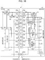
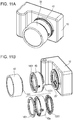
- Figs. 1A and 1B are block diagrams of a camera accessory and imaging apparatus according to an embodiment of the present invention.
- Fig. 1A is a diagram exemplarily describing a camera system including a first lens unit (hereinafter referred to as first lens) 100, serving as an accessory according to the embodiment of the present invention, and a camera body 10 serving as a first imaging apparatus to which the first lens 100 can be directly detachably attached.
- Fig. 1B is a diagram describing the configuration of a mount portion 1 formed by the mounts in both the first lens 100 and the camera body 10. That is in Figs. 1A and 1B , the mounts provided on the first lens 100 and the mounts provided on the camera body 10 are collectively referred to as the mount portion 1. The mounts provided to the first lens 100 and camera body 10 will be described later.
- the camera body 10 has a charge-accumulation type solid-state imaging device (hereinafter referred to simply as sensor) 11, such as a complementary metal-oxide semiconductor (CMOS) sensor or the like, that performs photoelectric conversion of an optical image of a subject guided by a photography lens group 101 provided on the inner side of the first lens 100, and outputs electric signals.
- the camera body 10 also has an A/D conversion unit 12 that converts analog electric signals output from the imaging sensor 11 into digital signals, and an image processing unit 13 that generates image signals by performing various types of image processing on the digital signals.
- the image signals (still image and moving image) generated at the image processing unit 13 can be displayed on a display unit 14, and recorded in a recording medium 15.
- the camera body 10 also has memory 16.
- This memory 16 serves as a buffer for performing processing on image signals, and also stores operation programs (computer programs) that a later-described camera control unit 18 uses.
- the camera body 10 also has a camera operating input unit 17 including a power source switch for turning the power source on/off, a photography switch (release switch) for starting recording of image signals, and selection/settings switches for performing various types of menu settings, and so forth.
- the camera body 10 also has the camera control unit 18 including a microprocessor central processing unit (CPU) serving as a computer) that centrally controls the operations of the camera body 10 and first lens 100.
- the camera control unit 18 performs various types of settings based on signals input from the camera operating input unit 17, for example, and controls communication with a lens control unit 103 provided to the first lens 100 via the mount portion 1.
- the first lens 100 has the photography lens group 101 that is an optical member having multiple lens groups such as a zoom lens, shift lens, focus lens, and so forth, and light amount adjustment members such as a diaphragm and so forth.
- the first lens 100 has actuators for moving or operating optical members such as the multiple lens groups and diaphragm and so forth, and also has a lens drive unit 102 that drives the actuators.
- the first lens 100 also has the lens control unit 103 including a microprocessor (logical CPU (LCPU)) for lenses, that centrally controls operations of the first lens 100.
- the lens control unit 103 controls the lens drive unit 102 by communicating with the camera control unit 18 via the mount portion 1, for example.
- LCPU logical CPU
- the mount portion 1 including a camera mount face A provided on the camera body 10 side, and an accessory mount face B provided on the first lens 100 side, will be described with reference to Fig. 1B .
- the camera mount and accessory mount include a locking mechanism, a mount holding mechanism, and multiple electric terminals. The mounts will be described in detail later.
- the mount portion 1 has multiple terminals that are capable of electrically connecting the camera body 10 and the first lens 100 to each other, as illustrated in Fig. 1B .
- the multiple terminals are, at the camera mount face A, exposed to the outside of the camera body 10 as multiple camera-side contact pins provided to a contact holding member 203.
- the multiple terminals also are, at the accessory mount face B, exposed to the outside of the camera accessory (e.g., first lens 100) as multiple accessory-side contact faces provided to a contact face holding member 303.
- the contact pins and the contact faces of the camera body 10 side and the camera accessory (e.g., first lens 100) side are electrically connected among mutually corresponding contacts, in a state where the camera accessory is mounted to the camera body 10.
- a camera power source unit 19 generates communication control power source (VDD) as power source to be supplied to a mounted camera accessory via a VDD terminal, and power source to be supplied to a first communication I/F unit 21a via a power source switching unit 20.
- the camera power source unit 19 also generates driving power source (VBAT) as power source to be supplied to the mounted camera accessory via a VBAT terminal.
- VDD communication control power source
- VBAT driving power source
- the camera power source unit 19 generates a 3.3 V power source as a power source to be supplied to the camera control unit 18, first communication I/F unit 21a, and a second/third communication I/F unit 21b.
- the camera power source unit 19 also generates 3.0 V power source as a power source to be supplied to the first communication I/F unit 21a and second/third communication I/F unit 21b via the power source switching unit 20.
- the power source switching unit 20 is connected to the camera power source unit 19.
- the power source switching unit 20 supplies only one or the other of the VDD and 3.0 V power source, generated at the camera power source unit 19, to the first communication I/F unit 21a as power source Vs for communication interface. Switching of power source voltage is executed following instructions from the camera control unit 18.
- a lens power source 104 generates a 3.0 V power source, as a power source voltage for supply to the lens control unit 103 and a lens-side I/F unit 106, based on VDD supplied from the camera body 10 side.
- driving power source VBAT
- a drive circuit unit 105 at the first lens 100 side via a VBAT terminal from the above-described camera power source unit 19.
- the power source voltage for the lens control unit 103 and lens-side I/F unit 106 is the same (3.0 V) in the present embodiment, a configuration may be made where the voltage level that the lens control unit 103 exhibits is 3.3 V. In this case, there is the need to supply power source of a voltage level of 3.0 V and 3.3 V to the lens-side I/F unit 106, so the lens power source 104 generates power sources of 3.0 V and 3.3 V.
- VDD terminals 203a and 303a are terminals that supply communication control power source (VDD) as communication power primarily used for communication control, to the camera accessory (e.g., the first lens 100) from the camera body 10.
- VDD communication control power source
- the camera accessory e.g., the first lens 100
- the voltage of power source supplied to the first lens 100 is 5.0 V
- the voltage of supplied power source will change depending on the type of accessory mounted to the camera body 10.
- VBAT terminals 203b and 303b are terminals that supply driving voltage source (VBAT) that is driving power used for operating the mechanical driving units of the actuators used for driving the diaphragm and focus lens, from the camera side to the camera accessory side.
- the VBAT terminals 203b and 303b are terminals used to supply power source other than the above-described communication power.
- the voltage of the power source serving as driving power supplied to the first lens 100 is 4.25 V.
- the VDD terminals 203a and 303a and VBAT terminals 203b and 303b described above are power source terminals for supplying power source from the camera body 10 to the camera accessory, for example.
- DGND terminals 203m and 303m are grounding terminals GND terminals) corresponding to the communication control power source VDD.
- grounding in the present embodiment means to set the voltage level of the grounding terminals to generally the same level as the negative pole side of the power source such as a battery or the like.
- PGND terminals 203d and 303d are grounding terminals for connecting the camera body 10, and a mechanical drive system including motors (actuators) and the like provided to a camera accessory (e.g., the first lens 100), to ground level. That is to say, the PGND terminals 203d and 303d are grounding terminals (GND terminals) corresponding to the driving power source VBAT.
- the DGND terminals 203m and 303m and PGND terminals 203d and 303d described above are grounding terminals for grounding various types of power source systems in the camera body 10 and accessory to the ground level.
- MIF terminals 203e and 303e are terminals for detecting that the camera accessory (e.g., the first lens 100) has been mounted to the camera body 10.
- the MIF terminals 203e and 303e detect that the first lens 100 has been mounted to the camera body 10.
- the camera control unit 18 detects that the camera accessory has been mounted to or detached from the camera body 10, by detecting the voltage level that the MIF terminals 203e and 303e indicated. Based on this detection, the camera control unit 18 starts supply of power source to power source terminals after having detected mounting of the camera accessory, for example, and effects control to start communication between the camera body 10 and camera accessory.
- TYPE terminals 203c and 303c are terminals for distinguishing the type of camera accessory (e.g., the first lens 100) mounted to the camera body 10.
- the camera control unit 18 detects the value of voltage of signals indicated by the TYPE terminals 203c and 303c, and distinguishes the type of camera accessory mounted to the camera body 10 based on this value.
- the first lens 100 is pull-down connected to the DGND terminal at a predetermined resistance value. This resistance value differs depending on the type of the camera accessory.
- the multiple communication terminals provided to the mount portion 1 are divided into multiple communication systems (groups), and each communication system is capable of performing communication independently.
- LCLK terminals 203h and 303h, DCL terminals 203f and 303f, and DLC terminals 203g and 303g are a first communication system that performs first communication.
- DLC2 terminals 203i and 303i are a second communication system that performs second communication, which is independent from the first communication.
- CS terminals 203k and 303k, and DCA terminals 203j and 303j are a third communication system that performs third communication, which is independent from the first and second communication.
- the camera control unit 18 and lens control unit 103 can perform communication independently with the first through third, via the above-described multiple communication terminals.
- LCLK terminals 203h and 303h are terminals of the first communication system, and are terminals for communication clock signals output from the camera body 10 to the camera accessory (e.g., the first lens 100), and terminals for the camera body 10 to monitor the busy state of the accessory.
- DCL terminals 203f and 303f are terminals of the first communication system, and are communication data terminals for performing bidirectional communication between the camera body 10 and the camera accessory (e.g., the first lens 100).
- DLC terminals 203g and 303g are terminals of the first communication system, and are terminals for communication data output from the camera accessory (e.g., the first lens 100) to the camera body 10.
- CMOS output type has switch output of voltage at both H (High) and L (Low).
- open type has switch output at only the L side.
- open type in the present embodiment means the so-called open drain type, this may be the open collector type.
- DLC2 terminals 203i and 303i are terminals of the second communication system, and are terminals for communication data output from the camera accessory (e.g., the first lens 100) to the camera body 10.
- DCA terminals 203j and 303j are terminals of the third communication system, and are terminals for communication data for performing bidirectional communication between the camera body 10 and the camera accessory (e.g., the first lens 100).
- CS terminals 203k and 303k are terminals of the third communication system, and are signals terminals for communication requests between the camera body 10 and camera accessory (e.g., the first lens 100). Note that in the present embodiment, in a case where the first lens 100 is mounted to the camera body 10, the communication voltage at the corresponding terminals in the first through third communication systems is 3.0 V.
- the configuration of the camera mount 201 and the lens mount (accessory mount) 301 according to the present embodiment will be described with reference to Figs. 2A through 3B .
- the mount provided to the imaging apparatus side will be referred to as camera mount
- the mount provided to the lens unit side will be referred to as lens mount.
- mounts on a later-described conversion adapter the side that is mounted to the imaging apparatus will be referred to as lens mount
- the side mounted to the lens unit will be referred to as camera mount.
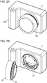
- Figs. 2A and 2B are external perspective views of the camera body 10 and first lens 100 according to the embodiment of the present invention.
- Fig. 2A illustrates a state in which the first lens 100 is mounted to the camera body 10
- Fig. 2B illustrates a state in which the first lens 100 has been removed from the camera body 10.
- the camera body 10 and first lens 100 have a ring-shaped camera mount 201 and ring-shaped lens mount 301, which each have contact faces which are parallel in a direction orthogonal to the optical axis and as such are arranged to cooperate with each other in use.
- the above-described optical axis is parallel to a center axis passing through the center of an aperture of the camera mount and lens mount.
- the center axis of the camera mount 201 and the center axis of the lens mount 301 are same as each of the optical axes of the camera mount 201 and lens mount 301, respectively.
- a configuration may be employed where this is realized by differing the center axis of the mount from the optical axis.
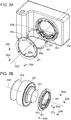
- Figs. 3A and 3B are disassembled perspective views of the camera body 10 and first lens 100 according to the embodiment of the present invention.
- Fig. 3A illustrates a disassembled perspective view of the camera body 10
- Fig. 3B illustrates a disassembled perspective view of the first lens 100.
- a first optical axis (first center axis) 3000 indicates a light flux passing through the center of the camera mount 201 of the camera body 10 as illustrated in Fig. 3A .
- an optical axis 3001 is an axis for describing a light flux representing an optical image of a subject that is guided by the first lens 100.
- a lock pin 202 is a first restricting member (lock member) for restricting (locking) the mounted state of the camera body 10 and camera accessory.
- the lock pin 202 is capable of advancing and retreating in a direction parallel to the first optical axis 3000. Specifically, when the first lens 100 is mounted to the camera body 10, the lock pin 202 enters a lock groove 301z that is a second restricting member provided to the lens mount 301, and locks the state of the first lens 100 being mounted to the camera body 10.
- the locking of the first lens 100 mounted to the camera body 10 can be disengaged by the user operating a lock disengaging member (omitted from illustration) connected to the lock pin 202, thereby retracting the lock pin 202 from the lock groove 301z. Note that even in a case of further rotating the first lens 100 and camera body 10 relative to each other in the mounting direction with the lock disengaging member operated, rotation beyond a lock abutting face 301y is restricted (see Fig. 7A ).
- the contact holding member 203 is holding means for holding later-described (see Figs. 8A and 8B ) multiple contact pins (electrical contact unit) 203a through 203k and 203m, provided on the camera body 10 side. Note that in the present embodiment, the contact pins and contact faces corresponding to the above-described terminals are denoted by the same part numerals as the terminals for the sake of description.
- a camera body member 204 is a camera housing that holds the members of the camera body 10. Specifically, the above-described camera mount 201 and contact holding member 203 are fastened to the camera body member 204 by camera mount fastening screws 205a through 205d and contact holding member fastening screws that are omitted from the illustration. Also, camera mount fastening screws 205a through 205d are positioned at positions where none of multiple leaf springs 206a, 206b, and 206c are positioned on the camera mount 201. Furthermore, camera mount fastening screws 205a through 205d are exposed at the contact faces of the camera mount 201 which is in contact with the contact face of the lens mount 301. Although the camera body member 204 holds an unshown imaging unit to which the aforementioned imaging sensor 11 is mounted, and a shutter unit that is omitted from illustration, description will be omitted.
- the lens mount biasing member 206 is a biasing means at the imaging apparatus side to pull lens claws 301d and 301e, which are multiple bayonet claws provided to the later-described lens mount 301, toward the camera mount 201 side.
- the lens mount biasing member 206 has multiple leaf springs 206a, 206b, and 206c, and the bayonet claws provided to the first lens 100 are biased in the optical axis direction by the leaf springs. Note that the lens mount biasing member 206 is held between the camera mount 201 and camera body member 204 in a space formed therebetween.
- a front lens 101a and rear lens 101b are optical members making up the photography lens group 101, as illustrated in Fig. 3B . While the photography lens group 101 has multiple lenses, only the front lens 101a disposed at the subject-side end and the rear lens 101b disposed at the camera body 10 side end are illustrated in the present embodiment to simplify description.
- a lens barrel 302 is a holding member that holds the photography lens group 101.
- the lens mount 301 is fastened to the lens barrel 302 by lens mount fastening screws 304a through 304d.
- a contact face holding member 303 is holding means for holding multiple contact faces (electrical contact units) 303a through 303k and 303m provided to a later-described (see Figs. 9A and 9B ) first lens 100 side.
- the contact face holding member 303 is fastened to the lens mount 301 by lens contact holding portion fastening screws 305a and 305b.
- the lens mount fastening screws 304a through 304d are exposed at the contact faces of the lens mount 301 which is in contact with the contact face of the camera mount 201. Configuration of Bayonet Claws at Camera Body 10 Side
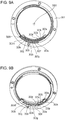
- Figs. 4A through 4C are diagrams exemplarily describing a case of viewing the camera mount 201 according to the embodiment of the present invention from the photographer side of the camera body 10 (rear face side of the camera body 10).
- Fig. 4A is a diagram illustrating angle ranges that camera mount claws (hereinafter referred to simply as camera claws) and camera mount recesses (hereinafter referred to simply as camera recesses) having the lock pin 202 as a reference occupy in the circumferential direction of the camera mount 201.
- the camera recesses of the camera mount 201 are notched portions between adjacent camera claws.
- Fig. 4B is a diagram illustrating angle ranges that multiple camera claws 201a through 201c occupy in the circumferential direction of the camera mount 201.
- Fig. 4C is a cross-sectional diagram taken along cross-section IVC-IVC in Fig. 4B .
- protrusions protruding from recesses in the inner radial direction at the camera mount side will be referred to as camera claws
- protrusions protruding from recesses in the outer diameter direction at the later-described lens mount (accessory mount) side will be referred to as lens mount claws.
- the side of the camera mount 201 as viewed from the side of the photographer (rear face of the camera body 10) of the camera body 10 will be referred to as rear face side, and the opposite side will be referred to as front face side (or camera accessory side).
- a first camera claw 201a, second camera claw 201b, and third camera claw 201c are provided in order, to the camera mount 201 in the circumferential direction (inner radial direction), as illustrated in Figs. 4A and 4B .
- the camera claw that is provided at a position farthest from the lock pin 202 is the first camera claw 201a.
- the second camera claw 201b and third camera claw 201c are then consecutively provided in order from the first camera claw 201a in a clockwise direction.
- recesses which are a first camera recess 201d, second camera recess 201e, and third camera recess 201f are provided in order, to the camera mount 201 in the circumferential direction (inner radial direction).
- the recess that is provided at a position nearest to the lock pin 202 is the second camera recess 201e.
- the third camera recess 201f and first camera recess 201d are then consecutively provided in order from the second camera recess 201e in a clockwise direction.
- a fitting member 201x that restricts movement of the camera accessory in a direction parallel to the optical axis when the camera accessory is mounted, is provided to the camera mount 201 side in the circumferential direction.
- the diameter of the fitting member 201x in a direction orthogonal to the optical axis at the camera mount 201 is the mount diameter.
- the camera claws of the camera body 10 are inserted into the lens mount recesses of the first lens 100, and the lens mount claws at the first lens 100 side are inserted into the camera recesses at the camera body 10 side.
- This state is a mounting start state (first state).
- accessory mount recesses will be referred to simply as accessory recesses, and accessory mount claws will be reference to simply as accessory claws.
- this is lens recesses and lens claws.
- the camera mount 201 and lens mount 301 are then rotated relative to each other from the mounting start state, whereby the camera claws and lens claws engage in the radial direction orthogonal to the optical axis, and transition to a state where the lens claws are biased by the above-described lens mount biasing member 206.
- this state relative positional relation between the camera body 10 and the first lens 100 transitions to a locked state where the lock pin 202 has fit into the lock groove 301z as described above.
- This state is a mounting complete state (second state). Note that in the mounting complete state, contact of corresponding terminals at the camera mount 201 and lens mount 301 is complete.
- the camera claws and accessory claws are so-called bayonet claws, and as described above, have shapes so that the first lens 100 can be mounted (can be coupled) to the camera body 10 by the so-called bayonet coupling method by engaging of the camera claws and accessory claws.
- the end portions are denoted with part numerals in order from the first camera claw 201a in the clockwise direction, when viewing the camera mount 201 from the rear face side, as described above.
- angles that the camera claws and camera recesses occupy in the circumferential direction of the camera mount 201 are stipulated as follows in the present embodiment.
- the angle ⁇ a 48°
- the angle ⁇ b 40°
- the angle ⁇ c 92°
- the angle is 57°
- the angle is 66°
- the angle is 57°.
- the angles in the clockwise direction where the camera claws are disposed in the circumferential direction of the camera mount 201 with the position of the lock pin 202 (referred to as reference position) as a reference are stipulated as follows.
- the first camera claw 201a is disposed between 169° to 217° with the reference position as a start point.
- the second camera claw 201b is disposed between 274° to 314° with the reference position as a start point.
- the third camera claw 201c is disposed between 20° to 112° with the reference position as a start point.
- the third camera claw 201c overlaps a first camera mount center line 3003 that extends in the vertical direction from the center axis parallel with the optical axis of the camera mount 201 in the radial direction of the camera mount 201.
- the first camera mount center line 3003 is a line that, in a normal position of the camera body 10 where the lock pin 202 is situated at the left side when viewing the camera mount 201 from the rear face side, extends in the gravitational direction and the opposite direction from the gravitational direction, from the center (optical axis) of the camera mount 201.
- the first camera mount center line 3003 is a vertical line that passes through the optical axis in a normal position of the camera.
- the first camera mount center line 3003 is a vertical line that passes though the center of the camera mount 201 and orthogonal to the center axis of the camera mount 201 when the camera body 10 is placed on a horizontal plane.
- a line that, in a vertical position of the camera body 10 where the lock pin 202 is situated at the top side when viewing the camera mount 201 from the front face side, extends in the gravitational direction and the opposite direction from the gravitational direction, from the center (optical axis) of the camera mount 201 is a second camera mount center line 3002. That is to say, the second camera mount center line 3002 is a horizontal line that passes through the optical axis when the camera body 10 is in the normal position. The second camera mount center line 3002 overlaps the lock pin 202 and first camera claw 201a in the radial direction of the camera mount 201. Note that the first camera mount center line 3003 and the second camera mount center line 3002 are generally orthogonal.
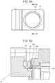
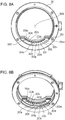
- Figs. 5A and 5B are diagrams exemplarily describing engagement of the camera body 10 and first lens 100 by camera claws at a normal position of the camera body 10 according to the embodiment of the present invention.
- Fig. 5A is a diagram viewing a state where the first lens 100 is mounted to the camera body 10 from the front face side.
- Fig. 5B is a partial cross-sectional view of the camera body 10 and first lens 100 taken along cross-section VB-VB in Fig. 5A . Note that in Figs. 5A and 5B , the camera body 10 is positioned in the above-described normal position, and, in this state, a camera grip 204a provided to the camera body member 204 is situated to the left side when viewing the camera body 10 from the front face side.
- Figs. 6A and 6B are diagrams exemplarily describing engagement of the camera body 10 and first lens 100 by bayonet claws at a vertical position of the camera body 10 according to the embodiment of the present invention.
- Fig. 6A is a diagram viewing a state where the first lens 100 is mounted to the camera body 10 from the front face side.
- Fig. 6B is a partial cross-sectional view of the camera body 10 and first lens 100 taken along cross-section VIB-VIB in Fig. 6A . Note that in Figs. 6A and 6B , the camera body 10 is positioned in the above-described vertical position, and the camera grip 204a in this state is situated to the top side when viewing the camera body 10 from the front face side.
- a gap occurs between the camera and interchangeable lens in a direction orthogonal to the optical axis, due to dimensional tolerance of the two, and looseness of the lens as to the camera increases due to this gap.
- the looseness of the lens is greater the farther away from positions where the bayonet claws engage each other in the circumferential direction of the lens.
- the looseness in the gravitational direction (bowing) of the interchangeable lens as to the camera is greater due to the weight of the interchangeable lens itself.
- the third camera claw 201c that has the widest angle of the camera-side bayonet claws overlaps the first camera mount center line 3003 in the radial direction of the camera mount, as illustrated in Fig. 5B .
- the first camera mount center line 3003 overlaps the position where the third camera claw 201c and a later-described third lens claw 301f are engaged.
- looseness (bowing) of the camera accessory such as the first lens 100 or the like mounted to the camera body 10 in the gravitational direction, can be suppressed in the normal position of which the frequency of usage is highest for operating the imaging apparatus, for example.
- the gap ⁇ 1 illustrated in Fig. 5B can be kept from becoming large, so looseness of the first lens 100 as to the camera body 10 in the direction indicated by the arrow in Fig. 5B can be suppressed.
- the first camera claw 201a overlaps the second camera mount center line 3002, as illustrated in Fig. 6B in the radial direction of the camera mount 201.
- the second camera mount center line 3002 overlaps the position where the first camera claw 201a and a later-described first lens claw 301d are engaged.
- looseness (bowing) of the camera accessory such as the first lens 100 or the like mounted to the camera body 10 in the gravitational direction, can be suppressed in the vertical position of the imaging apparatus as well, for example.
- the gap ⁇ 2 illustrated in Fig. 6B can be kept from becoming large, so looseness of the first lens 100 as to the camera body 10 in the direction indicated by the arrow in Fig. 6B can be suppressed.
- the angle of the third camera claw 201c in the circumferential direction of the camera mount 201, situated at the top side in a case where the camera body 10 is at the normal position, is greater than the sum of angles of the first claw 201a and second claw 201b situated at the lower side, as illustrated in Fig. 4B . More precisely, the total sum of angles in the circumferential direction of the camera claws provided to the camera mount 201 is greater at the upper side of the second camera mount center line as a reference as compared to the lower side.
- the layout of the camera claws and recesses is decided so as to satisfy the two following expressions. ⁇ c ⁇ ⁇ a + ⁇ b ⁇ a 1 + ⁇ c > ⁇ a 2 + ⁇ b
- the strength of camera claws at the upper side of the second camera mount center line 3002 (opposite side from the gravitational direction) that indicates the horizontal direction of the camera mount 201 can be made to be greater than the camera claws at the lower side (gravitational direction). Accordingly, in the normal position of the camera body 10 regarding which the frequency of usage is highest in a state where the first lens 100 is mounted, the camera body 10 according to the present embodiment can reduce looseness (bowing) of the first lens 100 as to the camera body 10 in the gravitational direction.
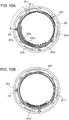
- FIGs. 7A and 7B are diagrams exemplarily describing a case of viewing the lens mount 301 according to the embodiment of the present invention from the rear face side in a state where the first lens 100 is mounted to the camera body 10 (side where the camera body 10 is attached).
- Fig. 7A exemplarily describes angles of the claws and recesses in the circumferential direction at the lens mount 301 side
- Fig. 7B is a cross-sectional view taken along cross-section VIIB-VIIB in Fig. 7A . Note that in the following description, the camera body 10 is positioned in the normal position in the state illustrated in Figs. 7A and 7B .
- a first lens claw 301d, second lens claw 301e, and third lens claw 301f are provided in order, to the lens mount 301 in the circumferential direction (inner radial direction), as illustrated in Figs. 7A .
- the lens claw that is provided at a position farthest from the lock groove 301z is the first lens claw 301d.
- the second lens claw 301e and third lens claw 301f are then consecutively provided in order from the first lens claw 301d in a clockwise direction.
- recesses which are a first lens recess 301a, second lens recess 301b, and third lens recess 301c are provided in order, to the lens mount 301 in the circumferential direction (inner radial direction).
- the recess that is provided at a position nearest to the lock groove 301z is the third lens recess 301c.
- the first lens recess 301a and second lens recess 301b are then consecutively provided in order from the third lens recess 301c in a clockwise direction.
- a fitting member 301x that restricts movement in a direction parallel to the optical axis of the imaging apparatus when mounted on the imaging apparatus, is provided to the lens mount 301 side in the circumferential direction.
- the diameter of the fitting member 301x in a direction orthogonal to the optical axis at the lens mount 301 side is the mount diameter.
- the end portions are denoted with part numerals in order from the first lens claw 301d in the clockwise direction, when viewing the lens mount 301 from the rear face side, as described above.
- the angles that the lens claws and lens recesses occupy in the circumferential direction of the lens mount 301 are stipulated as follows in the present embodiment.
- the angle ⁇ d 53°
- the angle ⁇ e 62°
- the angle ⁇ f 53°
- the angle is 52°
- the angle is 44°
- the angle is 96°.
- the angles where the lens claws are disposed in the circumferential direction of the lens mount 301 with the position of the lock groove 301z (referred to as reference position) as a reference in the clockwise direction are stipulated as follows.
- the first lens claw 301d is disposed between 159° to 212° with the reference position as a start point.
- the second lens claw 301e is disposed between 256° to 318° with the reference position as a start point.
- the third lens claw 301f is disposed between 54° to 107° with the reference position as a start point.
- the second lens claw 301e overlaps a first lens mount center line 3005 that extends in the vertical direction of the lens mount 301, in the radial direction of the lens mount 301.
- the third lens claw 301f overlaps the first lens mount center line 3005 in the radial direction of the lens mount 301.
- the first lens mount center line 3005 is a line that, in a normal position of the camera body 10 to which the first lens 100 has been mounted, extends in the gravitational direction and the opposite direction from the gravitational direction, from the center (optical axis) of the camera mount 301.
- the first lens mount center line 3005 is a vertical line that passes through a center of the lens mount 301 and is orthogonal to the center axis of the lens mount 301 when the camera body 10 to which the first lens 100 is attached is placed on a horizontal plane.
- This second lens mount center line 3006 overlaps the lock groove 301z and first lens claw 301d in the radial direction of the lens mount 301.
- the first lens mount center line 3005 and second lens mount center line 3006 are mutually orthogonal.
- the second lens claw 301e and third lens claw 301f overlap the first lens mount center line 3005 in the radial direction of the lens mount 301, as illustrated in Fig. 7A .
- the first lens mount center line 3005 overlaps two positions of engaging positions between lens claws and camera claws. In this case for example, in the normal position of the imaging apparatus 10 regarding which the frequency of usage is highest, looseness (bowing) of the first lens 100 mounted to the camera body 10 in the gravitational direction can be reduced.
- the first lens claw 301d overlaps the second lens mount center line 3006 in the radial direction of the lens mount 301, as illustrated in Fig. 7A .
- the second lens mount center line 3006 overlaps the position where the first lens claw 301d and the first camera claw 201a engage.
- looseness (bowing) of the first lens 100 mounted to the camera body 10 in the gravitational direction can be reduced.
- the second camera mount center line 3002 and second lens mount center line 3006 overlap a lock region where the lock pin 202 and lock groove 301z are fit, as described above.
- the engaging position of the first camera claw 201a and first lens claw 301d and the above-described lock region overlap the mount center lines extending in the gravitational direction and the opposite direction thereof.
- looseness (bowing) of the first lens 100 mounted to the camera body 10 in the gravitational direction can be suppressed even more effectively.
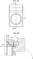
- Figs. 8A and 8B are external perspective views viewing a camera mount 201 according to the embodiment of the present invention from the front face side (subject side).
- Fig. 8A is an external view of the camera mount 201 from the optical axis direction
- Fig. 8B is an external perspective view of the camera mount 201 from above.
- the contact holding member 203, and contact pins 203a through 203k and 203m that are held by the contact holding member 203 are disposed following the circumferential direction of the camera mount 201 on the inner side of the camera mount 201, as illustrated in Fig. 8A .
- An array line on which the contact points are disposed is illustrated in Fig. 8A as an array line 3007.
- the contact pins 203a through 203k and 203m are movable pins that can advance and retreat (protrude and retract) in a direction parallel to the optical axis 3000, and are biased from behind toward the first lens 100 side by leaf springs (omitted from illustration).
- the contact pins 203a through 203k and 203m have the functions of the above-described respective terminals, and the part numerals by which the contact pins are denoted are the same as those of the terminals, to facilitate description.
- the contact pins 203a, 203b, 203c, and 203d are higher in the direction parallel to the optical axis 3000 (toward the front face) as compared to the other contact pins.
- a configuration may be employed where this is realized by differing the amount of protrusion of the contact pins from the contact holding member 203.
- the contact pins at the camera side and the contact face on the lens side slide over each other.
- contact pins other than the contact pin situated at the edge in the rotational direction to complete mounting of the interchangeable lens slide over one or another contact face provided to the lens side Accordingly, the more times the camera accessory is attached/detached to/from the camera, the more the contact pins and contact faces are worn.
- the contact height of the camera-side contact pins and the interchangeable-lens-side contact faces are differed in a direction parallel to the optical axis 3000, between an upper tier and a lower tier.
- the contact holding member 203 has a step (height level difference) in a direction parallel to the optical axis 3000, with the contact pins 203a through 203d being provided to the upper tier, and the contact pins 203e through 203k and 203m being provided to the lower tier.
- the contact face holding member 303 also is stepped in a direction parallel to the optical axis 3001, with the contact faces 303a through 303d provided to the lower tier, and the contact faces 303e through 303k and 303m provided to the upper tier.
- the upper tier of the contact holding member 203 at the camera mount 201 side is a tier protruding toward the front face side (subject side) of the first lens 100 when the first lens 100 is mounted to the camera body 10.
- the lower tier of the contact holding member 203 is a tier recessed toward the rear face side (imaging sensor 11 side) of the camera body 10.
- the upper tier of the contact face holding member 303 at the lens mount 301 side is a tier protruding toward the rear face side (imaging sensor 11 side) of the first lens 100 when the first lens 100 is mounted to the camera body 10.
- the lower tier of the contact face holding member 303 is a tier recessed to the front face side (subject side) of the camera body 10.
- the contact pins provided to the upper tier side of the contact holding member 203 and the contact faces provided to the lower tier side of the contact face holding member 303 are electrically in contact among corresponding terminals. Also, in a case where the lens mount 301 is mounted to the camera mount 201, the contact pins provided to the lower tier side of the contact holding member 203 and the contact faces provided to the upper tier side of the contact face holding member 303 are electrically in contact among corresponding terminals.
- the steps at the camera mount 201 side and lens mount 301 side have a mutually engageable shape, so when mounting the lens mount 301 to the camera mount face A, the contact pins at the camera side and contact faces at the lens side that are provided to different steps do not come into contact.
- the contact pins 203e through 203k and 203m do not come into contact with the contact faces 303a through 303d. Also, when relatively rotating the first lens 100 as to the camera body 10 from the mounting completed state to the mounting start state, the contact pins 203e through 203k and 203m do not come into contact with the contact faces 303a through 303d. That is to say, the number of times of sliding between contact pins and contact faces can be reduced at both the camera mount 201 side and lens mount 301 side.
- the contact pins at the camera body 10 side and the contact faces at the first lens 100 side are all in a non-contact state in the mounting start state of the first lens 100 as to the camera body 10, so short-circuiting among terminals before completion of mounting of the first lens 100 can be prevented.
- Figs. 9A and 9B are external perspective views of the lens mount 301 according to the embodiment of the present invention, as viewed from the side to which the camera mount 201 is mounted (rear face side).
- Fig. 9A is an external view of the lens mount 301 from the optical axis direction
- Fig. 9B is an external perspective view of the lens mount 301 from above.
- the contact face holding member 303, and contact faces 303a through 303k and 303m that are held by the contact face holding member 303 are disposed on the inner side of the lens mount 301, following the circumferential direction of the lens mount 301, as illustrated in Fig. 9A .
- An array line on which the contact points are disposed is illustrated in Fig. 9A as an array line 3008.
- the contact faces 303a through 303k and 303m have the functions of the above-described respective terminals, and the part numerals by which the contact faces are denoted are the same as those of the terminals, to facilitate description.
- the contact faces 303a, 303b, 303c, and 303d are lower in the direction parallel to the optical axis 3001 as compared to the other contact faces.
- the above-described configuration is realized by differing the amount of protrusion of the contact face holding member 303 in the optical axis direction in the present embodiment.
- the contact faces 303a through 303d do not come into contact with the contact pins 203e through 203k and 203m. Also, when relatively rotating the first lens 100 as to the camera body 10 from the mounting completed state to the mounting start state, the contact faces 303a through 303d do not come into contact with the contact pins 203e through 203k and 203m. That is to say, the number of times of sliding between contact pins and contact faces can be reduced at both the camera mount 201 side and lens mount 301 side.
- the contact face holding member 303 has a first guiding inclined face 303n and a second guiding inclined face 303p for drawing corresponding contact pins toward the rear face direction (imaging sensor 11 side) when mounting the first lens 100 to the camera body 10, as illustrated in Fig. 9B .
- the contact pressure of the contact pins provided to the camera body 10 side as to the contact face holding member 303 gradually changes, whereby deformation and wear of the contact pins provided to the camera body 10 can be reduced.
- Figs. 10A and 10B are diagrams exemplarily describing a contact state between terminals on the camera body 10 and first lens 100 according to the embodiment of the present invention.
- Fig. 10A is a diagram for describing the contact state of the terminals in the mounting start state where mounting of the first lens 100 to the camera body 10 has been started.
- Fig. 10B is a diagram for describing the contact state of the terminals in the mounting completed state where mounting of the first lens 100 to the camera body 10 has been completed. Note that in the state illustrated in Fig.
- the contact pins 203m and 203k at the camera mount 201 side in the optical axis direction overlap the contact faces 303a and 303b at the lens mount face B side.
- the height of the contact holding member 203 and the contact face holding member 303 in the direction parallel with the optical axis is made to differ for each region, as described above, none of the contact pins and contact faces come into contact in the state illustrated in Fig. 10A .
- the state illustrated in Fig. 10B is a state where the first lens 100 has been rotated by generally 60° as to the camera body 10 from the state illustrated in Fig. 10A toward the direction indicated by the arrow (see Fig. 10A ). That is to say, in the present embodiment, the relative rotational angle of the camera body 10 and first lens 100 from the mounting start state to the mounting completed state is generally 60°. Note that in the state illustrated in Fig. 10B , the lock pin 202 is in the state of fitting the lock groove 301z (locked).
- Rotating the first lens 100 by generally 60° as to the camera body 10 guides the first lens claw 301d into the rear face side (imaging sensor 11 side) of the first camera claw 201a and the two are engaged with each other in the optical axis direction.
- the second lens claw 301e is guided into the rear face side (imaging sensor 11 side) of the second camera claw 201b, and these are engaged with each other in the optical axis direction.
- the third lens claw 301f is guided into the rear face side (imaging sensor 11 side) of the third camera claw 201c, and these are engaged with each other in the optical axis direction.
- the positions of the lens claws provided to the first lens 100 are positioned by being biased toward the rear face side by the lens mount biasing member 206 provided to the camera mount 201 side, thereby coupling the camera body 10 and the first lens 100.
- the contact pins at the camera body 10 side are pressed toward the rear face side (imaging sensor 11 side) by the first guiding inclined face 303n and second guiding inclined face 303p.
- the contact pins of the camera body 10 come into contact with corresponding places on the contact faces 303a through 303k and 303m at the lens mount 301 side in a state of being pressed, and come into contact with the respectively corresponding contact faces in the mounting completed state.
- the contact pin 203m provided to the camera mount 201 side and the contact face 303e provided to the lens mount 301 start coming into contact first.
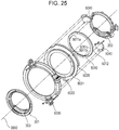
- Figs. 11A and 11B are diagrams describing the first conversion adapter 40 that is mountable to the camera body 10, and a second lens unit 50.
- Fig. 11A illustrates an external perspective view of the second lens unit 50 having been mounted to the camera body 10 via the first conversion adapter 40.
- Fig. 11B illustrates an external perspective view of a state where the camera body 10, first conversion adapter 40, and second lens unit 50 have each been detached.
- the second lens unit (hereinafter referred to as second lens) 50 has a lens mount 501 that is long in flange focal distance, but has the same mount diameter as the camera mount 201, as to the camera body 10. That is to say, the second lens 50 has the same mount diameter as the above-described first lens 100, but unlike the first lens 100, is a camera accessory that is not compatible with direct mounting to the camera body 10.
- Figs. 12A and 12B are diagrams for describing the second conversion adapter 70 that is mountable to a camera body 60 and the first lens 100.
- Fig. 12A illustrates an external perspective view of a state where the first lens 100 is mounted to the camera body 60 via the second conversion adapter 70
- Fig. 12B illustrates an external perspective view where the camera body 60, second conversion adapter 70, and first lens 100 have each been detached.
- the camera body 10 and camera body 60, and the first lens 100 and second lens 50 have the same mount diameter, it is difficult for a user to judge which imaging apparatuses and which lens units have flange focal distances that are compatible for direct mounting.
- lens units that are compatible can be directly mounted to a certain imaging apparatus, so that imaging apparatuses and lens units that have mutually incompatible flange focal distances are not erroneously directly mounted.
- a conversion adapter needs to be interposed between the two to adjust the flange focal distance.
- the focal point may not be accurately formed, as described above.
- the one side and other side of the conversion adapter preferably have configurations to restrict imaging apparatuses and camera accessories that are directly mountable.
- a conversion adapter is preferable where one end side is only mountable to this imaging apparatus, and the other end side is only mountable to this lens unit. Also, in a case of mounting a lens unit having a short flange focal distance to an imaging apparatus having a long flange focal distance, a conversion adapter is preferable where one end side is only mountable to this imaging apparatus, and the other end side is only mountable to this lens unit.
- the first conversion adapter 40 has the lens mount 1301 attached to an adapter barrel 40a by fastening screws (omitted from illustration), at one end side in the optical axis direction.
- This lens mount 1301 is an accessory mount that is detachable from the camera mount 201 provided to the camera body 10 described above.
- a camera mount 1401 is attached to the adapter barrel 40a by fastening screws (omitted from illustration), at the other end side of the first conversion adapter 40 in the optical axis direction.
- This camera mount 1401 is a camera mount that is detachable from the lens mount 501 of the second lens 50. Note that the camera mount 1401 of the first conversion adapter 40 is attached so that the imaging plane of the imaging sensor 11 of the will be situated at a position corresponding to the flange focal distance of the second lens 50.
- the second conversion adapter 70 has the lens mount 1501 attached to an adapter barrel 70a by fastening screws (omitted from illustration), at one end side in the optical axis direction.
- This lens mount 1501 is an accessory mount that is detachable from the camera mount 401 provided to the camera body 60.
- the camera mount 1201 is attached to the adapter barrel 70a by fastening screws (omitted from illustration), at the other end side of the second conversion adapter 70 in the optical axis direction.
- This camera mount 1201 is a camera mount that is detachable from the lens mount 301 of the first lens 100, as described above.
- first optical member 701a and a second optical member 701b are provided to the second conversion adapter 70, between the adapter barrel 70a and the lens mount 1501 in the optical axis direction.
- the first optical member 701a and second optical member 701b enable the second conversion adapter 70 to extend length of the flange focal distance of the first lens 100 in accordance with the imaging plane of the imaging sensor disposed in the camera body 60. While the optical members have been illustrated as two lenses for the sake of convenience, this is not restrictive. Configuration of First Conversion Adapter 40
- Figs. 13A through 13C are diagrams for exemplarily describing displacement angles of bayonet claws in the camera mount 1401 provided on one end of the first conversion adapter 40.
- Fig. 13A is a diagram illustrating angle ranges that camera claws and camera recesses occupy in the circumferential direction of the camera mount 1401 with the lock pin 1401z as a reference, as viewed from the rear face side (camera body 10 side).
- Fig. 13A is a diagram illustrating angle ranges that camera claws and camera recesses occupy in the circumferential direction of the camera mount 1401 with the lock pin 1401z as a reference, as viewed from the rear face side (camera body 10 side).
- FIG. 13B is a diagram illustrating angle ranges that multiple camera claws 1401a through 1401c occupy in the circumferential direction of the camera mount 1401, as viewed from the rear face side (camera body 10 side).
- Fig. 13C is a cross-sectional diagram taken along cross-section XIIIB-XIIIB in Fig. 13B .
- the first conversion adapter 40 is a mount adapter used for mounting the second lens unit 50 that has a long flange focal distance to the camera body 10 that has a short flange focal distance. Accordingly, it is preferable for the first conversion adapter 40 to be configured such that the camera body 60 that has a long flange focal distance cannot be directly mounted to the lens mount 1301, and the first lens 100 that has a short flange focal distance cannot be directly mounted to the camera mount 1401. According to this configuration, the positional relation of claws and recesses can be satisfied so that the lens mount 1301 provided to one end (first end) of the first conversion adapter 40 and the camera mount 1401 provided to the other end (second end) cannot each be directly mounted.
- a first camera claw 1401a, second camera claw 1401b, and third camera claw 1401c are provided in order, to the camera mount 1401 in the circumferential direction (inner radial direction).
- the camera claw that is provided at a position farthest from the lock pin 1401z is the first camera claw 1401a.
- the second camera claw 1401b and third camera claw 1401c are then consecutively provided in order from the first camera claw 1401a in a clockwise direction.
- recesses which are a first camera recess 1401d, second camera recess 1401e, and third camera recess 1401f are provided in order, to the camera mount 1401 in the circumferential direction (inner radial direction).
- the recess that is provided at a position nearest to the lock pin 1401z is the second camera recess 1401e.
- the third camera recess 1401f and first camera recess 1401d are then consecutively provided in order from the second camera recess 1401e in a clockwise direction.
- a fitting member 1401x that restricts movement of the camera accessory in a direction parallel to the optical axis when the camera accessory is mounted, is provided to the camera mount 1401 side.
- the diameter of the fitting member 1401x in a direction orthogonal to the optical axis at the camera mount 1401 side is the mount diameter.
- the way of bayonet coupling of the first conversion adapter 40 and second lens 50 is the generally the same as the way of bayonet coupling of the camera body 10 and first lens 100 described above, so description will be omitted.
- the end portions are denoted with part numerals in order from the first camera claw 1401a in the clockwise direction, when viewing the camera mount 1401 from the rear face side, as described above.
- the angles that the camera claws and camera recesses occupy in the circumferential direction of the camera mount 1401 (angle ranges) in the first conversion adapter 40 according to the present embodiment are stipulated as follows.
- the angle ⁇ 1 56°
- the angle ⁇ 2 62°
- the angle ⁇ 3 62°
- the angle is 57°
- the angle is 66°
- the angle is 57°. That is to say the camera mount 1401 has different angles for the camera claws with respect to the above-described camera mount 201 of the camera body 10, but the angles of the camera recesses are the same.
- the angles where the camera claws are disposed on the circumferential direction of the camera mount 1401 with the position of the lock pin 402 (referred to as reference position) as a reference are stipulated as follows.
- the first camera claw 1401a is disposed between 159° to 215° with the reference position as a start point.
- the second camera claw 1401b is disposed between 272° to 334° with the reference position as a start point.
- the third camera claw 1401c is disposed between 40° to 102° with the reference position as a start point.
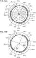
- Figs. 14A and 14B are diagrams exemplarily describing angles of disposing the bayonet claws on the lens mount 1301 provided to the other end of the first conversion adapter 40.
- Fig. 14A is a diagram illustrating angle ranges that lens claws and lens recesses occupy in the circumferential direction of the lens mount 1301 with the lock groove 1301z as a reference, as viewed from the rear face side.
- Fig. 14B is a diagram illustrating angle ranges that multiple lens recesses 1301a through 1301c occupy in the circumferential direction of the lens mount 1301, as viewed from the rear face side.
- the angles (angle ranges) that the lens recesses occupy in the circumferential direction of the lens mount 1301 are, represented by ⁇ 4 as the angle of the first lens recess 1301a and ⁇ 5 as the angle of the second lens recess 1301b, as illustrated in Fig. 14B .
- ⁇ 4 as the angle of the first lens recess 1301a
- ⁇ 5 as the angle of the second lens recess 1301b
- the angles of the claws and recesses in the circumferential direction, on the lens mount 1301 and camera mount 1401 provided to the first conversion adapter 40, will be compared.
- the angle ⁇ 5 of the second lens recess 1301b having the smallest angle is 44°
- the angle ⁇ 1 of first camera claw 1401a having the smallest angle is 56°. That is to say, the claw having the smallest angle at the camera mount 1401 side is larger than the recess having the smallest angle at the lens mount 1301 side ( ⁇ 5 ⁇ ⁇ 1).
- FIGs. 15A and 15B are diagrams exemplarily describing a mounting method of a predetermined imaging apparatus 1000 and a predetermined lens unit 2000 having claws and recesses that interfere with each other.
- Fig. 15A is a diagram exemplarily describing a frontal view of partway through mounting a predetermined lens unit to a predetermined imaging apparatus that have claws and recesses that interfere with each other.
- Fig. 15B is a cross-sectional view taken along cross-section XVB-XVB in Fig. 15A .
- a camera claw is inserted into a lens recess, and from this state, the lens mount and camera mount are rotated relatively to each other, as illustrated in Figs. 15A and 15B .
- this interference with each other is resolved during the relative rotation of the lens mount and camera mount, and transition can be made to a state where the camera claw is inserted into this lens recess.
- the lens unit can be mounted to the camera body.
- the claws and recesses on the lens mount 1301 side and camera mount 1401 side are disposed such that the angle of a predetermined lens recess adjacent to a reference lens claw is smaller than the angle of two camera claws adjacent to a reference camera recess.
- the angles ⁇ 4 and ⁇ 5 of the first lens recess 1301a and second lens recess 1301b adjacent to the first lens claw 1301d are smaller than the angles ⁇ 1 and ⁇ 2 of the first camera claw 1401a and second camera claw 1401b adjacent to the first camera recess 1401d.
- ⁇ 4 (52°) is smaller than ⁇ 1 (56°)
- ⁇ 5 (44°) is smaller than ⁇ 2 (62°) ( ⁇ 4 ⁇ ⁇ 1, ⁇ 5 ⁇ ⁇ 2). Accordingly, even if an attempt is made to insert the first lens claw 1301d into the first camera recess 1401d, the second lens claw 1301e interferes with the second camera claw 1401b in a sure manner, as well does the third lens claw 1301f with the first camera claw 1401a, as illustrated in Figs. 16A and 16B .
- Figs. 16A and 16B are diagrams exemplarily describing the way in which claws interfere with each other when attempting to mount the lens mount 1301 side to the camera mount 1401 side according to the embodiment of the present invention.
- Fig. 16A illustrates the way in which the third lens claw 1301f and the first camera claw 1401a interfere
- Fig. 16B illustrates the way in which the second lens claw 1301e and the second camera claw 1401b interfere.
- incompatible lens units and imaging apparatuses, and the mount portions of conversion adapters are configured so that two claws of each other out of the claws that an incompatible lens unit and imaging apparatus have interfere with each other in the present embodiment. According to this configuration, the risk of an incompatible lens unit being erroneously mounted to an imaging apparatus, or an incompatible lens unit and imaging apparatus being erroneously mounted to mount units provided to both ends of a conversion adapter, can be reduced.
- the present embodiment further takes a configuration where the angles of at least two adjacent lens recesses are smaller than the angles of all camera claws.
- the angles ⁇ 4 and ⁇ 5 of the first lens recess 1301a and second lens recess 1301b in the circumferential direction are smaller than the angles ⁇ 1 through ⁇ 3 of the first through third camera claws 1401a through 1401c in the circumferential direction.
- the relation between the claws and recesses at the lens mount 1301 side and the camera mount 1401 side according to the present embodiment satisfy ⁇ 4 ⁇ ⁇ 1, ⁇ 4 ⁇ ⁇ 2, ⁇ 4 ⁇ ⁇ 3, ⁇ 5 ⁇ ⁇ 1, ⁇ 5 ⁇ ⁇ 2, and ⁇ 5 ⁇ ⁇ 3.
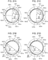
- Figs. 17A through 17D is a diagram exemplarily describing a case of attempting to insert incompatible claws into recesses at the lens mount 1301 side and camera mount 1401 side according to the embodiment of the present invention.
- Fig. 17A illustrates the way in which the third lens claw 1301f and third camera claw 1401c interfere in a case of attempting to insert the first lens claw 1301d into the third camera recess 1401f.
- Fig. 17B illustrates the way in which second lens claw 1301e and first camera claw 1401a interfere in a case of attempting to insert the first lens claw 1301d into the third camera recess 1401f.
- Fig. 17A illustrates the way in which the third lens claw 1301f and third camera claw 1401c interfere in a case of attempting to insert the first lens claw 1301d into the third camera recess 1401f.
- Fig. 17B illustrates the way in which second lens claw 1301e and first camera claw 1401a interfere in a case of attempting
- FIG. 17C illustrates the way in which the third lens claw 1301f and second camera claw 1401b interfere in a case of attempting to insert the first lens claw 1301d into the second camera recess 1401e.
- Fig. 17D illustrates the way in which the second lens claw 1301e and third camera claw 1401c interfere in a case of attempting to insert the first lens claw 1301d into the second camera recess 1401e.
- the lens claws and camera claws interfere in at least two places in the present embodiment, regardless of the relative rotational angle of the lens mount 1301 and camera mount 1401. According to this configuration, erroneous mounting of a lens unit and conversion adapter having the lens mount 301 or the lens mount 1301 to an imaging apparatus and conversion adapter having the camera mount 401 or the camera mount 1401 can be prevented even more effectively.
- the second conversion adapter 70 is a mount adapter used for mounting the first lens 100 that has a short flange focal distance to the camera body 60 that has a long flange focal distance.
- the lens mount 1501 is provided at one end (third end) side of the second conversion adapter 70, and the camera mount 1201 is provided at the other end (fourth end).
- the camera mount 1201 of the second conversion adapter 70 has the same configuration as the camera mount 201 of the camera body 10 that is the first imaging apparatus described above.
- the lens mount 1501 of the second conversion adapter 70 has the same configuration as the lens mount 501 of the second lens 50 described above.
- the second conversion adapter 70 prefferably be configured such that the camera body 10 that has a short flange focal distance cannot be directly mounted to the lens mount 1501, and the second lens 50 that has a long flange focal distance cannot be directly mounted to the camera mount 1201.
- This configuration can be realized by satisfying the positional relation of claws and recesses so that the lens mount 1501 provided to one end (third end) of the second conversion adapter 70 and the camera mount 1201 provided to the other end (fourth end) cannot each be directly mounted.
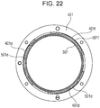
- Figs. 18A and 18B are diagrams exemplarily describing angles of disposing bayonet claws in the camera mount 1201 provided on one end of the second conversion adapter 70.
- Fig. 18A is a diagram illustrating angle ranges that camera claws and camera recesses occupy in the circumferential direction of the camera mount 1201 with the lock pin 1202 as a reference, as viewed from the rear face side.
- Fig. 18B is a diagram illustrating angle ranges that, regarding multiple camera claws 1201a through 1201c, the claws occupy in the circumferential direction of the camera mount 1201, as viewed from the rear face side. Note that the angles of disposing the claws and recesses on the camera mount 1201 of the second conversion adapter 70 are the same as the camera mount 201 of the camera body 10 described earlier, so description will be omitted.
- the angle from the sixth end 1201c2 of the third camera claw 1201c to the third end 1201b1 of the second camera claw 1201b, in the circumferential direction of the camera mount 1201 including the first camera claw 1201a, is ⁇ 6 (162°).
- the angle from the second end 1201a2 of the first camera claw 1201a to the fifth end 1201c1 of the third camera claw 1201c, in the circumferential direction of the camera mount 1201 including the second camera claw 1201b, is ⁇ 7 (163°).
- the angle from the fourth end 1201b2 of the second camera claw 1201b to the first end 1201a1 of the first camera claw 1201a, in the circumferential direction of the camera mount 1201 including the third camera claw 1201c, is ⁇ 8 (215°).
- Figs. 19A through 19C are diagrams exemplarily describing angle so disposing bayonet claws in a lens mount 1501 provided on the other end of the second conversion adapter 70.
- Fig. 19A is a diagram illustrating angle ranges that lens claws and lens recesses occupy in the circumferential direction of the lens mount 1501 with the lock groove 1501z as a reference, as viewed from the rear face side.
- Fig. 19B is a diagram illustrating angle ranges where recesses are provided regarding the multiple lens recesses 1501a through 1501c in the circumferential direction of the lens mount 1501, as viewed from the rear face side.
- Fig. 19C is a cross-sectional diagram taken along cross-section XIXC-XIXC in Fig. 19B .
- a first lens claw 1501d, second lens claw 1501e, and third lens claw 1501f, are provided in order, to the camera mount 1501 in the circumferential direction (inner radial direction). Note that in a case of viewing the lens mount 1501 from the rear face side as illustrated in Fig. 19A , the lens claw that is provided at a position farthest from the lock groove 1501z is the first lens claw 1501d. The second lens claw 1501e and third lens claw 1501f are then consecutively provided in order from the first lens claw 1501d in a clockwise direction.
- recesses which are a first lens recess 1501a, second lens recess 1501b, and third lens recess 1501c are provided in order, to the lens mount 1501 in the circumferential direction (inner radial direction). Note that in a case of viewing the lens mount 1501 from the rear face side as illustrated in Fig. 19A , the recess that is provided at a position nearest to the lock groove 1501z is the third lens recess 1501c. The first lens recess 1501a and second lens recess 1501b are then consecutively provided in order from the third lens recess 1501c in a clockwise direction.
- the end portions are denoted with part numerals in order from the first lens claw 1501d in the clockwise direction, when viewing the lens mount 1501 from the rear face side, as described above.
- the angles that the lens claws and lens recesses occupy in the circumferential direction of the lens mount 1501 are stipulated as follows.
- the angle of the first lens claw 1501d is 53°
- the angle of the second lens claw 1501e is 62°
- the angle of the third lens claw 1501f is 53°. That is to say, the angles of the lens claws on the lens mount 1501 side are the same as the angles of the lens claws on the lens mount 1301 side described earlier.
- the angles of the lens recesses at the lens mount 1501 side differ from the angles of the lens recesses at the lens mount 1301 side described above. Specifically, the angle of the first lens recess 1501a is 60°, the angle of the second lens recess 1501b is 66°, and the angle of the third lens recess 1501c is 66°.
- the angles in the clockwise direction where the lens claws are disposed on the circumferential direction of the lens mount 1501 with the position of the lock groove 1501z (referred to as reference position) as a reference are stipulated as follows.
- the first lens claw 1501d is disposed between 157° to 210° with the reference position as a start point.
- the second lens claw 1501e is disposed between 276° to 338° with the reference position as a start point.
- the third lens claw 1501f is disposed between 44° to 97° with the reference position as a start point.
- a fitting member 1501x that restricts movement of the imaging apparatus in a direction parallel to the optical axis when mounted to the imaging apparatus is provided to the lens mount 1501 side.
- the diameter of the fitting member 1501x in a direction orthogonal to the optical axis at the camera mount 1501 side is the mount diameter.
- the mount diameters of the camera mounts and lens mounts described above are generally the same length.
- the angle from the fifth end 1501f1 of the third lens claw 1501f to the second end 1501d2 of the first lens claw 1501d, in the circumferential direction of the lens mount 1501 including the first lens recess 1501a, is ⁇ 9 (166°).
- the angle from the first end 1501d1 of the first lens claw 1501d to the fourth end 1501e2 of the second lens claw 1501e, in the circumferential direction of the lens mount 1501 including the second lens recess 1501b, is ⁇ 10 (181°).
- the angle from the third end 1501e1 of the second lens claw 1501e to the sixth end 1501f2 of the third lens claw 1501f, in the circumferential direction of the lens mount 1501 including the third lens recess 1501c, is ⁇ 11 (181°).
- angles of the claws and recesses in the circumferential direction will be compared between the camera mount 1201 and lens mount 1501 provided to the second conversion adapter 70.
- the angle (92°) of the third camera claw at the camera mount 1201 side is larger than the angles (66°) of the second and third lens recesses 1501b and 1501c that are the largest angle of the lens recesses at the lens mount 1501 side. That is to say, the angle of at least one camera claw at the camera mount 1201 side is larger than the angle of the lens recess having the largest angle at the lens mount 1501 side.
- the claws at the camera mount 1201 side and recesses at the lens mount 1501 side at least one or more camera claw and lens recess interfere with each other. Accordingly, even if an attempt is made to mount the lens unit to the camera body so that the optical axis at the camera mount 1201 side and lens mount 1501 side are generally parallel to each other, the claws and recesses interfere, so the lens unit cannot be mounted to the camera body.
- claws of the camera mount side can be inserted into recesses of the lens mount side, in the same way as the description of the first conversion adapter made above.
- the lens mount and camera mount are rotated relative to each other, and the lens unit can be mounted to the camera body.
- Figs. 20A and 20B are diagrams exemplarily describing the way in which claws interfere with each other, when attempting to mount a reference claw at the lens mount 1501 side to a reference recess at the camera mount 1201 side according to the embodiment of the present invention.
- Fig. 20A illustrates the way in which the third lens claw 1501f and the third camera claw 1201c interfere
- Fig. 20B illustrates the way in which the second lens claw 1501e and the third camera claw 1201c interfere.
- the third camera claw 1201c interferes with the second and third lens claws 1501e and 1501f.
- the total sum of the angles of one reference lens claw, another lens claw adjacent thereto in the clockwise direction, and a lens recess situated between these lens claws is taken as a third angle.
- the total sum of the angles of one reference camera recess, another camera recess adjacent thereto in the clockwise direction, and a camera claw portion situated therebetween is taken as a second angle.
- the total sum of the angles of one reference lens claw, another lens claw adjacent thereto in the counterclockwise direction, and a lens recess situated between these lens claws is taken as a first angle.
- the total sum of the angles of one reference camera recess, another camera recess adjacent thereto in the counterclockwise direction, and a camera claw portion situated therebetween, is taken as a fourth angle.
- the claws and recesses at the camera mount 1201 side and lens mount 1501 side are disposed in the circumferential direction so as to satisfy ⁇ 6 ⁇ ⁇ 9, ⁇ 6 ⁇ ⁇ 10, ⁇ 6 ⁇ ⁇ 11, ⁇ 7 ⁇ ⁇ 9, ⁇ 7 ⁇ ⁇ 10, and ⁇ 7 ⁇ ⁇ 11.
- the total sum of the angles of two claws other than the reference claw described above, and a lens recess situated therebetween, is taken as a fifth angle.
- Figs. 21A through 21D are diagrams exemplarily describing the way in which claws interfere with each other, when attempting to mount a claw other than the reference claw at the lens mount 1501 side to a reference recess at the camera mount 1201 side according to the embodiment of the present invention.
- Fig. 21A illustrates the way in which the first lens claw 1501d and the third camera claw 1201c interfere in a case of attempting to insert the second lens claw 1501e into the first camera recess 1201d.
- Fig. 21B illustrates the way in which the third lens claw 1501c and the third camera claw 1201c interfere in a case of attempting to insert the second lens claw 1501e into the first camera recess 1201d.
- Fig. 21A illustrates the way in which the first lens claw 1501d and the third camera claw 1201c interfere in a case of attempting to insert the second lens claw 1501e into the first camera recess 1201d.
- Fig. 21A illustrates the way in which the first
- FIG. 21C illustrates the way in which the second lens claw 1501e and the third camera claw 1201c interfere in a case of attempting to insert the third lens claw 1501f into the first camera recess 1201d.
- Fig. 21D illustrates the way in which the first lens claw 1501d and the third camera claw 1201c interfere in a case of attempting to insert the third lens claw 1501f into the first camera recess 1201d.
- Figs. 21A through 21D at least two lens claws and one camera claw interfere, regardless of the relative rotation angle of the lens mount 1501 and camera mount 1201 according to the present embodiment. According to this configuration, erroneous mounting of a lens unit and conversion adapter having the lens mount 501 or the lens mount 1501 to an imaging apparatus and conversion adapter having the camera mount 201 or the camera mount 1201 can be prevented even more effectively.
- Fig. 22 is a diagram exemplarily describing a state in which claws provided to the camera mount 401 side and lens mount 501 side according to the embodiment of the present invention are engaged.
- the first lens claw 1501d can be inserted into the first camera recess 1401d, as illustrated in Fig. 22 .
- Fig. 22 illustrates a state in which the camera mount 401 of the camera body 60 is engaging the lens mount 501 of the second lens 50.
- the first lens claw 501d can be inserted into the first camera recess 401d, as illustrated in Fig. 22 .
- the second lens claw 501e can be inserted into the second camera recess 401e.
- the third lens claw 501f can be inserted into the third camera recess 401f.
- the camera mount 401 side and the lens mount 501 side are a combination compatible with being directly mounted to each other.
- the camera mount 201 side and the lens mount 301 side are a combination compatible to being directly mounted to each other, as illustrated in Fig. 10A .
- the camera mount 401 (1401) corresponding to an imaging apparatus that has a long flange focal distance (e.g., the camera body 60), and the lens mount 501 (1501) corresponding to a lens unit that has a long flange focal distance (e.g., the second lens 50) can be directly mounted to each other.
- the camera mount 201 (1201) corresponding to an imaging apparatus having a short flange focal distance (e.g., the camera body 10) and the lens mount 501 (1501) corresponding to a lens unit that has a long flange focal distance (e.g., the second lens 50) cannot be directly mounted to each other.
- the camera mount 201 (1201) corresponding to an imaging apparatus that has a short flange focal distance (e.g., the camera body 10) and the lens mount 301 (1301) corresponding to a lens unit that has a short flange focal distance (e.g., the first lens 100) can be directly mounted to each other.
- the camera mount 401 (1401) corresponding to an imaging apparatus that has a long flange focal distance (e.g., the camera body 60) and the lens mount 301 (1301) corresponding to a lens unit that has a short flange focal distance (e.g., the first lens 100) cannot be directly mounted to each other.
- an imaging apparatus and camera accessory employing the configuration of the above-described embodiment can prevent erroneous mounting of an imaging apparatus and camera accessory that have generally the same mount diameter but are not mutually compatible.
- Fig. 23 is a diagram describing a frontal view of the camera body 10 according to an embodiment of the present invention.
- a total of twelve contact pins, i.e. multiple contact pins 203e through 203k and 203m, are held in the contact holding member 203 as electric terminals corresponding to multiple contact faces provided on the first lens 100 described above, for example, as illustrated in Fig. 23 .
- the contact pin 203f that is a DCL terminal is disposed at a position overlapping the first camera mount center line 3003 of the camera mount 201, in the normal position of the camera body 10, as illustrated in Fig. 23 .
- the first camera mount center line 3003 is a vertical center line that extends from the center (optical axis) of the camera mount 201 in the gravitational direction and the opposite direction from the gravitational direction, in the normal position of the camera body 10.
- This first camera mount center line 3003 also overlaps a camera accessory attachment index 201g in the radial direction of the camera mount 201, besides the contact pin 203f.
- the contact pin 203f is disposed directly beneath the attachment index 201g and the optical axis 3000 of the camera mount 201.
- the contact pin 203f is disposed at the farthest position from an imaging region (aperture) 600 of the camera body 10, or from the second lens mount center line 3002.
- the distance from the second lens mount center line 3002 to the contact pin 203f will be referred to as "distance a", as illustrated in Fig. 23 .
- a contact pin can be disposed on the first camera mount center line 3003 by employing the above-described configuration, so the contact pin 203f situated directly below the optical axis can be used as a reference for measuring positions of other contact pins, when working on the contact holding member 203 and so forth. Accordingly, the working precision and measurement precision of the contact pins on the contact holding member 203 can be improved.
- employing the above configuration enables the user to confirm the position of the first camera mount center line 3003 and the optical axis 3000, by confirming a line between the contact pin 203f and the attachment index 201g.
- the position of the first camera mount center line 3003 and the optical axis 3000 can be confirmed without providing an index indicating the position of the optical axis or the like on the camera mount 201.
- the contact pins are formed of a metal material, so in a case where the distance from the contact pins to the aperture is short, light rays reflected by the contact pins (inner reflection) may affect photography of the subject, and an image having an unnatural brightness may be obtained.
- a method is conceivable where the distance between the contact pins is shortened, and the distances from the optical axis to the contact pins in a direction parallel to the optical axis is increased overall.
- the distance between the contact pins is short, which increases the risk of contact pins sliding over contact faces when mounting the camera accessory, and of short-circuiting of contact pins due to adhesion of foreign matter to the contact pins, and so forth. Accordingly, an appropriate distance needs to be provided among the contact pins.
- the contact pin 203f situated at the generally middle portion of the camera mount 201 in the circumferential direction is disposed at the farthest position from the aperture 600 in the present embodiment.
- the contact pin 203f is situated at the farthest position from the second lens mount center line 3002, out of the multiple contact pins that the camera mount 201 has.
- the camera body 10 is configured so that the distances from the aperture 600 (or second lens mount center line 3002) to the contact pin 203a and contact pin 203m that are on the ends of the multiple contact pins on the camera mount 201 are generally the same. Note that in the present embodiment, the distances from the first camera mount center line 3003 and the contact pin 203f to the contact pin 203a and contact pin 203m are also generally the same.
- the camera body 10 is configured such that a predetermined contact pin is disposed on the first camera mount center line 3003, and distance between the pins is adjusted so that that the distances from the contact pins on the ends to the aperture are the same.
- Fig. 24 is a partially enlarged view of the camera mount 201 according to the embodiment of the present invention.
- contact pins 203a and 203b VDD terminal and VBAT terminal
- contact pins 203g and 203h DLC terminal and LCLK terminal
- An angle ⁇ formed between the contact pin 203a and contact pin 203b is formed to be greater than an angle ⁇ formed between the contact pin 203g and contact pin 203h, in the circumferential direction of the camera mount 201.
- the pitch (distance) between each of the contact pins situated to the left side from the contact pin 203f in Fig. 24 is the same as or greater than the pitch between each of the contact pins situated to the right side from the contact pin 203f in Fig. 24 .
- the pitch between the contact pins in one of the regions is greater than the pitch between the contact pins in the other of the regions.
- the contact pins used for electric power supply are situated on the region to the left side of the first camera mount center line 3003 in Fig. 24 , which is the aforementioned one of the regions.
- the contact pins used for communication are situated on the region to the right side of the first camera mount center line 3003 in Fig. 24 , which is the aforementioned other of the regions.
- the pitch between contact pins is the distance between the centers of contact pins in the circumferential direction of the camera mount 201 in the present embodiment, this is not restrictive.
- the distance between conducting portions of the contact pins, or the distance between contact points when the contact pins are electrically connected to corresponding contact faces on the accessory mount side may be used as the pitch of contact pins.
- the contact pin 203a which corresponds to the VDD terminal is a contact pin that comes into contact with one of the contact faces on the lens mount 301 side last, when mounting the first lens 100 to the camera body 10, for example.
- the contact pin 203m which corresponds to the DGND terminal is a contact pin that comes into contact with one of the contact faces on the lens mount 301 side first, when mounting the first lens 100 to the camera body 10, for example.
- the second guiding inclined face 303p that the lens mount 301 of the camera accessory corresponding to the camera mount 201 has is situated to the left side from the contact pin 203f in Fig. 24 , in a state where the camera accessory is mounted. That is to say, the region of the camera mount 201 side corresponding to the second guiding inclined face 303p is on the left side of the contact pin in Fig. 24 , and is disposed on the side with fewer contact pins with the first camera mount center line 3003 as a reference. According to this configuration, the angle between contact pins can be made greater at the side corresponding to the guiding inclined face for terminals, with the first camera mount center line 3003 as a reference.
- the number of terminals (contact pins and contact faces) provided to the camera body 10 and first lens 100 is twelve, this is not restrictive.
- the above-described configuration is applicable as long as the number of terminals is an even number of four or greater.
- the roles of terminals situated on both ends of the mount in the circumferential direction, with the first mount center line as a reference, may be different from those of the above-described terminal 203a and terminal 203m.
- using the same pitch between all terminals and disposing one terminal overlapping the first camera mount center line 3003 enables the multiple terminals to be uniformly distributed in the right and left regions with the first camera mount center line 3003 as a reference.
- the above-described configuration has been described using the camera mount 201 provided to the camera body 10 as a reference, the above-described configuration is the same at the side of the lens mount (accessory mount) 301, provided on the first lens 100 for example, as well. That is to say, in a case where the lens mount 301 has an even number of contact faces, the contact face 303f situated at the generally middle portion in the circumferential direction of the of the lens mount 301 overlaps the first lens mount center line 3005 in the radial direction of the mount.
- the contact face 303a and contact face 303m situated on both ends of the lens mount 301 in the circumferential direction have generally the same distance to the aperture 600 (or second lens mount center line 3006) in a state where the camera mount 201 is mounted to the lens mount 301.
- the pitch between contact faces included in one of the regions where there are the contact faces used for electric power supply is a greater pitch than the pitch between contact faces included in the other of the regions where there are the contact faces used for communication.
- the contact pin 203a is the last terminal to come into contact with one of the contact faces at the accessory mount side
- the contact pin 203m is the first terminal to come into contact with one of the contact faces at the accessory mount side
- this relation is inverted at the accessory side. That is to say, the contact face 303a is the first terminal to come into contact with one of the contact pins at the camera mount side
- the contact face 303m is the last terminal to come into contact with one of the contact pins at the camera mount side.
- an interchangeable lens and an intermediate accessory such as a conversion adapter and an extension adapter (extension-tube)
- an interchangeable lens and an intermediate accessory such as a conversion adapter and an extension adapter (extension-tube)
- an extension adapter extension-tube
- Any sort of camera accessory may be employed as long as it is a device that has an accessory mount capable of directly connecting (coupling) to a camera mount provided to the above-described imaging apparatuses.
- both of the camera mount and accessory mount corresponding to each other have a pair of electric terminals through which electric connection is established in a mutually mounted state
- this is not restrictive.
- a configuration may be made having electric terminals that do not correspond to each other.
- a configuration may be made where a terminal that the camera body 10 does not have is provided to a camera accessory mountable to the camera body 10.
- each mount has three claws in the circumferential direction
- the number of claws is not restricted to three, as long as the conditions of the above-described embodiment are satisfied.
- a configuration may be made where each of the three claws provided to the mounts in the above-described embodiment is further divided. That is to say, a configuration may be made where one claw is one claw group made up of multiple claws. A case where a groove is provided to one claw falls under this, for example. In this case, the ranges of angles of claw groups disposed in the circumferential direction of the mounts is the same as those in the embodiment described above.
- the mount diameter of each mount is the inner diameter of a fitting portion provided to each mount, in a direction orthogonal to the optical axis, this is not restrictive.
- an inner diameter of which the radius is the distance from the center (optical axis) of each mount to multiple terminals may be used as the mount diameter, or an inner diameter of which the radius is the distance from the center (optical axis) of each mount to a claw or recess may be used as the mount diameter.
- Fig. 25 is a disassembled perspective view of a mount mechanism 5000 according to a modification of the present invention.
- Figs. 26A through 26C are diagrams for exemplarily describing a non-coupled state of the mount mechanism 5000 according to the modification of the present invention.
- Figs. 27A through 27C are diagrams for exemplarily describing a coupled state of the mount mechanism 5000 according to the modification of the present invention.
- the lens mount that is capable of bayonet-coupling to a movable mount portion 5010 of the mount mechanism 5000 is also illustrated, for the same of description. Members that are the same as in the above-described embodiment are denoted by the same reference numerals, and description thereof will be omitted.
- the mount mechanism 5000 has, in order from the side to which the lens mount is attached, an operation portion 5030, a fixed mount portion 5020, the movable mount portion 5010, and the contact holding member 203, centered on the optical axis 3000.
- the operation portion 5030 is ring-shaped operating means capable of rotating on a center axis, and is fixed to the movable mount portion 5010 by screws, by arm portions 5040.
- the operation portion 5030 and movable mount portion 5010 are fixed at two positions, using two arm portions 5040 disposed in an orthogonal direction as to the center axis. According to this configuration, by the operation portion 5030 being rotationally operated, the movable mount portion 5010 also rotates integrally with the center axis as the center.
- movable mount claws 5011a, 5011b, and 5011c are each capable of bayonet-coupling with bayonet claws 301a through 301c provided to the lens mount.
- a screw portion 5012 is also provided to the movable mount portion 5010 that has been threaded around the center axis, and the screwed state as to a later-described screw portion 5022 of the fixed mount portion 5020 changes in accordance with the rotation of the movable mount portion 5010 around the center axis.
- the fixed mount portion 5020 has a camera mount face 5021 that comes into contact with the mount face of the lens mount 301, and the screw portion 5022 with which the screw portion 5012 of the above-described movable mount portion 5010 is screwed. Unlike the above-described movable mount portion 5010, the fixed mount portion 5020 does not rotate on the center axis in accordance with rotation operations of the operation portion 5030.
- the bayonet coupling method of the mount mechanism 5000 according to the present modification will be described with reference to Figs. 26A through 27C .
- the bayonet claws provided to the lens mount are in a state of being capable to engage the movable mount claws 5011a through 5011c of the movable mount portion 5010, in a state of being passed through an opening portion of the operation portion 5030 and an opening portion of the fixed mount portion 5020.
- the state illustrated in Figs. 26A through 26C is a state where the operation portion 5030 is situated at an unlocked position.
- Fig. 26C is a cross-sectional diagram taken along cross-section XXVIC-XXVIC in Fig. 26B .
- Figs. 27A through 27C exemplify the mount mechanism 5000 in a state where the operation portion 5030 has been rotationally operated from this state.
- Figs. 27A through 27C The state illustrated in Figs. 27A through 27C is a state where the operation portion 5030 is situated in a locked position. In this state, the claws of each of the lens mount and movable mount portion 5010 overlap each other, and thereby are engaged in the center axis direction. In this state, the screwing state of the screw portion 5022 of the fixed mount portion 5020 and the screw portion 5012 of the movable mount portion 5010 changes in accordance with rotational operation of the operation portion 5030, and the movable mount portion 5010 moves toward the imaging device side in the center axis direction.
- Fig. 27C is a cross-sectional diagram taken along cross-section XXVIIC-XXVIIC in Fig. 27B . As illustrated in Figs.
- the movable mount portion 5010 moves away from the fixed mount portion 5020 in a center axis direction of the mount in accordance with a non-locked state of the mount mechanism 5000 changing to a locked state of the mount mechanism 5000.
- each of the movable mount claws 5011a through 5011c in a state of being engaged with the bayonet claws at the lens mount side moves toward the imaging apparatus side.
- the mount mechanism 5000 can move the movable mount portion in the center axis direction as to the fixed mount portion, by rotating the movable mount portion that has claws capable of engaging lens-mount-side claws on the center axis. According to this configuration, the mount mechanism 5000 according to the present embodiment can reduce occurrence of gaps (looseness) that occurs between the lens mount and camera-side mount in a coupled state.
Landscapes
- Physics & Mathematics (AREA)
- General Physics & Mathematics (AREA)
- Engineering & Computer Science (AREA)
- Multimedia (AREA)
- Signal Processing (AREA)
- Structure And Mechanism Of Cameras (AREA)
- Camera Bodies And Camera Details Or Accessories (AREA)
- Accessories Of Cameras (AREA)
Claims (16)
- Bildgebungsvorrichtung (10) mit:einer zweiten Befestigung (201), die zum Bajonettkoppeln mit einer ersten Befestigung (301) auf einem Zubehör (100) eingerichtet ist,wobei die zweite Befestigung (201) auf einer Anordnungslinie (3007), die der Umfangsrichtung der zweiten Befestigung (201) folgt, eine Vielzahl von Kontaktstiften (203a-203k, 203m) angeordnet hat und in einem Fall, dass die zweite Befestigung (201) mit der ersten Befestigung (301) bajonettgekoppelt wird, zur elektrischen Verbindung mit einer Vielzahl von Kontaktflächen (303a-303k, 303m), die auf der ersten Befestigung (301) vorgesehen ist, eingerichtet ist, wobei die Anzahl der Vielzahl von Kontaktstiften (203a-203k, 203m) eine gerade Zahl ist, die vier oder mehr beträgt,wobei in einer Normalstellung der Bildgebungsvorrichtung (10), in der sich ein Verriegelungsstift (202) der Bildgebungsvorrichtung (10) auf der rechten Seite befindet, wenn die Bildgebungsvorrichtung (10) vonseiten der zweiten Befestigung (201) betrachtet wird, an die die erste Befestigung (301) gekoppelt wird, eine Linie, die sich von einer Mittelachse der zweiten Befestigung (201) in der Gravitationsrichtung und einer Gegenrichtung zur Gravitationsrichtung erstreckt, als eine erste Befestigungsmittellinie (3003) genommen wird und eine Linie, die senkrecht zu der Mittelachse und der ersten Befestigungsmittellinie (3003) ist, als eine zweite Befestigungsmittellinie (3002) genommen wird,dadurch gekennzeichnet, dasswenn die Bildgebungsvorrichtung (10) aus einer Richtung parallel zur Mittelachse der zweiten Befestigung (201) betrachtet wird,die Vielzahl von Kontaktstiften (203a-203k, 203m) einen ersten Kontaktstift (203f) umfasst, der in der Radialrichtung der zweiten Befestigung (201) die erste Befestigungsmittellinie (3003) überlappt, unddie Vielzahl von Kontaktstiften (203-203k, 203m) einen zweiten Kontaktstift (203a) und einen dritten Kontaktstift (203m) umfasst, die im Wesentlichen den gleichen Abstand zur zweiten Befestigungsmittellinie (3002) haben, wobeider zweite Kontaktstift (203a) ein Kontaktstift ist, der sich an einem Ende auf einer Seite der Vielzahl von Kontaktstiften (203a-203k, 203m) befindet, die auf der Anordnungslinie (3007) angeordnet sind, undder dritte Kontaktstift (203m) ein Kontaktstift ist, der sich an einem Ende auf einer anderen Seite der Vielzahl von Kontaktstiften (203a-203k, 203m) befindet, die auf der Anordnungslinie (3007) angeordnet sind.
- Bildgebungsvorrichtung (10) nach Anspruch 1,
wobei die Bildgebungsvorrichtung (10) an einer hinteren Flächenseite der zweiten Befestigung (201) eine rechteckige Blende (600) hat, durch die ein optisches Bild eines Gegenstands auf dem Weg zu einer in der Bildgebungsvorrichtung (10) vorgesehenen Bildgebungseinrichtung (11) tritt,
und wobei der erste Kontaktstift (203f) unter der Vielzahl von Kontaktstiften (203a-203k, 203m) am weitesten von der Blende (600) entfernt ist. - Bildgebungsvorrichtung (10) nach Anspruch 2,
wobei der zweite Kontaktstift (203a) und der dritte Kontaktstift (203m) im Wesentlichem im gleichen Abstand zur Blende (600) positioniert sind. - Bildgebungsvorrichtung (10) nach einem der Ansprüche 1 bis 3,
wobei der zweite Kontaktstift (203m) und der dritte Kontaktstift (203m) im Wesentlichen den gleichen Abstand zur ersten Befestigungsmittellinie (3003) haben. - Bildgebungsvorrichtung (10) nach einem der Ansprüche 1 bis 4,
wobei bei der Vielzahl von Kontaktstiften (203a-203k, 203m) der Abstand zwischen nebeneinanderliegenden Kontaktstiften, die auf einer Seite der ersten Befestigungsmittellinie (3003) gelegen sind, größer als der Abstand zwischen nebeneinanderliegenden Kontaktstiften ist, die auf der anderen Seite der ersten Befestigungsmittellinie (3003) gelegen sind. - Bildgebungsvorrichtung (10) nach einem der Ansprüche 1 bis 5,
wobei ein Winkel (θα), der zwischen einer Linie, die sich von der Mittelachse der zweiten Befestigung (201) zum zweiten Kontaktstift (203a) erstreckt, und einer Linie ausgebildet ist, die sich von der Mittelachse der zweiten Befestigung (201) zu einem Kontaktstift erstreckt, der in der Umfangsrichtung der zweiten Befestigung (201) neben dem zweiten Kontaktstift (203a) liegt, größer als ein Winkel (θβ) ist, der zwischen einer Linie, die sich von der Mittelachse der zweiten Befestigung (201) zum dritten Kontaktstift (203m) erstreckt, und einer Linie ausgebildet ist, die sich von der Mittelachse der zweiten Befestigung (201) zu einem Kontaktstift erstreckt, der neben dem dritten Kontaktstift (203m) liegt. - Bildgebungsvorrichtung (10) nach einem der Ansprüche 1 bis 6,
wobei der erste Kontaktstift (203f) ein Anschluss ist, der zur Kommunikation zwischen der Bildgebungsvorrichtung (10) und dem Zubehör (100) eingerichtet ist,
wobei der zweite Kontaktstift (203a) ein Anschluss ist, der zur elektrischen Stromversorgung von der Bildgebungsvorrichtung (10) zum Zubehör (100) eingerichtet ist,
und wobei der dritte Stift (203m) ein Erdungsanschluss ist, der dem zweiten Kontaktstift (203a) entspricht. - Bildgebungsvorrichtung (10) nach einem der Ansprüche 1 bis 7,
wobei der zweite Kontaktstift (203a) ein Kontaktstift ist, der so eingerichtet ist, dass er in einer relativen Drehungsrichtung zum Bajonettkoppeln der zweiten Befestigung (201) und ersten Befestigung (301) als Letztes mit einer Vielzahl von Kontaktflächen (303a-303k, 303m) in Kontakt kommt, die aufseiten der ersten Befestigung (301) vorgesehen ist,
und wobei der dritte Kontaktstift (203m) ein Kontaktstift ist, der so eingerichtet ist, dass er in einer relativen Drehungsrichtung zum Bajonettkoppeln der zweiten Befestigung (201) und ersten Befestigung (301) als Erstes mit einer Vielzahl von Kontaktflächen (303a-303k, 303m) in Kontakt kommt, die aufseiten der ersten Befestigung (301) vorgesehen ist. - Zubehör (100) mit:einer zweiten Befestigung (301), die zum Bajonettkoppeln mit einer ersten Befestigung (201) auf einer Bildgebungsvorrichtung (10) eingerichtet ist,wobei die zweite Befestigung (301) auf einer Anordnungslinie (3008), die der Umfangsrichtung der zweiten Befestigung (301) folgt, eine Vielzahl von Kontaktflächen (303a-303k, 303m) angeordnet hat und in einem Fall, dass die zweite Befestigung (301) mit der ersten Befestigung (201) bajonettgekoppelt wird, zur elektrischen Verbindung mit einer Vielzahl von Kontaktstiften (203a-203k, 203m) eingerichtet ist, die auf der ersten Befestigung (201) vorgesehen ist, wobei die Anzahl der Vielzahl von Kontaktflächen (303a-303k, 303m) eine gerade Zahl ist, die vier oder mehr beträgt,wobei in einer Normalstellung der Bildgebungsvorrichtung (10), in der sich in einem Zustand, in dem sie mit dem Zubehör (100) bajonettgekoppelt ist, ein Verriegelungsstift (202) der ersten Befestigung (201) auf der rechten Seite befindet, wenn die Bildgebungsvorrichtung (10) vonseiten der ersten Befestigung (201) betrachtet wird, an die die zweite Befestigung (301) gekoppelt ist, eine Linie, die sich von einer Mittelachse der ersten Befestigung (201) in der Gravitationsrichtung und einer Gegenrichtung zur Gravitationsrichtung erstreckt, als eine erste Befestigungsmittellinie (3005) genommen wird und eine Linie, die senkrecht zu der Mittelachse und der ersten Befestigungsmittellinie (3005) ist, als eine zweite Befestigungsmittellinie (3006) genommen wird,dadurch gekennzeichnet, dasswenn das Zubehör (100) aus einer Richtung parallel zur Mittelachse der zweiten Befestigung (301) betrachtet wird,die Vielzahl von Kontaktflächen (303a-303k, 303m) eine erste Kontaktfläche (303f) umfasst, die in einem Zustand, in dem die zweite Befestigung (301) an die erste Befestigung (201) gekoppelt ist, die erste Befestigungsmittellinie (3005) überlappt, unddie Vielzahl von Kontaktflächen (303a-303k, 303m) eine zweite Kontaktfläche (303a) und eine dritte Kontaktfläche (303m) umfasst, die im Wesentlichen den gleichen Abstand zur zweiten Befestigungsmittellinie (3006) haben, wobeidie zweite Kontaktfläche (303a) eine Kontaktfläche ist, die sich an einem Ende auf einer Seite der Vielzahl von Kontaktflächen (303a-303k, 303m) befindet, die auf der Anordnungslinie (3008) angeordnet sind, unddie dritte Kontaktfläche (303m) eine Kontaktfläche ist, die an einem Ende auf einer anderen Seite der Vielzahl von Kontaktflächen (303a-303k, 303m) gelegen ist, die auf der Anordnungslinie (3008) angeordnet sind.
- Zubehör (100) nach Anspruch 9,
wobei die erste Kontaktfläche (303f) unter der Vielzahl von Kontaktflächen (303a-303k, 303m) in einem Zustand, in dem die zweite Befestigung (301) an die erste Befestigung (201) gekoppelt ist, am weitesten von einer rechteckigen Blende (600) entfernt ist, die auf der Bildgebungsvorrichtung (10) vorgesehen ist. - Zubehör (100) nach Anspruch 10,
wobei die zweite Kontaktfläche (303a) und die dritte Kontaktfläche (303m) in einem Zustand, in dem die zweite Befestigung (301) an die erste Befestigung (201) gekoppelt ist, im Wesentlichen im gleichen Abstand zur Blende (600) positioniert sind. - Zubehör (100) nach einem der Ansprüche 9 bis 11,
wobei die zweite Kontaktfläche (303a) und die dritte Kontaktfläche (303m) in einem Zustand, in dem die zweite Befestigung (301) an die erste Befestigung (201) gekoppelt ist, im Wesentlichen den gleichen Abstand zur ersten Befestigungsmittellinie (3005) haben. - Zubehör (100) nach einem der Ansprüche 9 bis 12,
wobei bei der Vielzahl von Kontaktflächen (303a-303k, 303m) in einem Zustand, in dem die zweite Befestigung (301) an die erste Befestigung (201) gekoppelt ist, der Abstand zwischen nebeneinanderliegenden Kontaktflächen, die auf einer Seite der ersten Befestigungsmittellinie (3005) gelegen sind, größer als ein Abstand zwischen nebeneinanderliegenden Kontaktflächen ist, die auf der anderen Seite der ersten Befestigungsmittellinie (3005) gelegen sind. - Zubehör (100) nach einem der Ansprüche 9 bis 13,
wobei ein Winkel, der zwischen einer Linie, die sich von der Mittelachse der ersten Befestigung (301) zur zweiten Kontaktfläche (303a) erstreckt, und einer Linie ausgebildet ist, die sich von der Mittelachse der ersten Befestigung (301) zu einer Kontaktfläche erstreckt, die in der Umfangsrichtung der zweiten Befestigung (301) neben der zweiten Kontaktfläche (303a) liegt, größer als ein Winkel ist, der zwischen einer Linie, die sich von der Mittelache der ersten Befestigung (301) zur dritten Kontaktfläche (303m) erstreckt, und einer Linie ausgebildet ist, die sich von der Mittelachse der ersten Befestigung (301) zu einer Kontaktfläche erstreckt, die neben der dritten Kontaktfläche (303m) liegt. - Zubehör (100) nach einem der Ansprüche 9 bis 14,
wobei die erste Kontaktfläche (303f) ein Anschluss ist, der zur Kommunikation zwischen dem Zubehör (100) und der Bildgebungsvorrichtung (10) eingerichtet ist, und die zweite Kontaktfläche (303a) ein Anschluss ist, der zur elektrischen Stromversorgung von der Bildgebungsvorrichtung (10) zum Zubehör (100) eingerichtet ist, und
wobei die dritte Kontaktfläche (303m) ein Erdungsanschluss ist, der der zweiten Kontaktfläche (303a) entspricht. - Zubehör (100) nach einem der Ansprüche 9 bis 15,
wobei die zweite Kontaktfläche (303a) eine Kontaktfläche ist, die so eingerichtet ist, dass sie in einer relativen Drehungsrichtung zum Bajonettkoppeln der ersten Befestigung (201) und zweiten Befestigung (301) als Erstes mit einem von einer Vielzahl von Kontaktstiften (203a-203k, 203m) in Kontakt kommt, die aufseiten der ersten Befestigung (201) vorgesehen ist, und
wobei die dritte Kontaktfläche (303m) eine Kontaktfläche ist, die so eingerichtet ist, dass sie in einer relativen Drehungsrichtung zum Bajonettkoppeln der ersten Befestigung (201) und zweiten Befestigung (301) als Letztes mit einem von einer Vielzahl von Kontaktstiften (203a-203k, 203m) in Kontakt kommt, die auf der ersten Befestigung (201) vorgesehen ist.
Applications Claiming Priority (1)
| Application Number | Priority Date | Filing Date | Title |
|---|---|---|---|
| JP2017108278 | 2017-05-31 |
Publications (2)
| Publication Number | Publication Date |
|---|---|
| EP3410188A1 EP3410188A1 (de) | 2018-12-05 |
| EP3410188B1 true EP3410188B1 (de) | 2021-07-07 |
Family
ID=62554969
Family Applications (1)
| Application Number | Title | Priority Date | Filing Date |
|---|---|---|---|
| EP18175011.8A Active EP3410188B1 (de) | 2017-05-31 | 2018-05-30 | Bildgebungsvorrichtung mit bajonetfassung und zubehör mit bajonetfassung |
Country Status (4)
| Country | Link |
|---|---|
| US (1) | US10591808B2 (de) |
| EP (1) | EP3410188B1 (de) |
| JP (1) | JP6743090B2 (de) |
| CN (2) | CN108989616B (de) |
Families Citing this family (4)
| Publication number | Priority date | Publication date | Assignee | Title |
|---|---|---|---|---|
| SG10201804096XA (en) | 2017-05-31 | 2018-12-28 | Canon Kk | Adapter device, imaging apparatus, and accessory |
| JP7309730B2 (ja) | 2018-08-29 | 2023-07-18 | キヤノン株式会社 | アダプタ装置、マウント装置およびアクセサリ |
| WO2020044501A1 (ja) * | 2018-08-30 | 2020-03-05 | キヤノン株式会社 | アクセサリ及びこれを装着可能な撮像装置、カメラシステム |
| CN112887456B (zh) * | 2018-11-06 | 2023-03-14 | Oppo广东移动通信有限公司 | 成像模组、摄像头组件及电子装置 |
Family Cites Families (85)
| Publication number | Priority date | Publication date | Assignee | Title |
|---|---|---|---|---|
| US4448509A (en) | 1981-10-26 | 1984-05-15 | Canon Kabushiki Kaisha | Interchangeable lens barrel with signal transfer contacts |
| US4464034A (en) | 1981-11-13 | 1984-08-07 | Nippon Kogaku K.K. | Device for electrically connecting lens and camera |
| US4437752A (en) | 1981-11-28 | 1984-03-20 | Canon Kabushiki Kaisha | Safety device for camera and accessory |
| US4565434A (en) | 1982-02-15 | 1986-01-21 | Canon Kabushiki Kaisha | Signal transferring device for photographic instrument or accessory |
| JPS59161133U (ja) | 1983-04-14 | 1984-10-29 | 株式会社 飯山コシナ | カメラ用レンズマウント |
| JPH0623821B2 (ja) | 1983-09-02 | 1994-03-30 | ミノルタカメラ株式会社 | バヨネットマウント装置とこの装置を用いる光学機器 |
| JP2530814B2 (ja) | 1986-01-31 | 1996-09-04 | 株式会社ニコン | 交換レンズ鏡筒のマウント構造 |
| GB2187856B (en) | 1986-02-17 | 1990-10-03 | Canon Kk | Mount device |
| JPS62195633A (ja) | 1986-02-24 | 1987-08-28 | Canon Inc | 光学付属品 |
| GB2199668B (en) | 1986-12-27 | 1991-05-22 | Canon Kk | Connector for a camera |
| US4924249A (en) | 1986-12-27 | 1990-05-08 | Canon Kabushiki Kaisha | Power supply device for camera |
| JPS63172257A (ja) | 1987-01-12 | 1988-07-15 | Canon Inc | 光学付属機器の電気回路接続用コネクタ |
| JP2681924B2 (ja) | 1987-05-13 | 1997-11-26 | 株式会社ニコン | 防水カメラ及び防水カメラ用交換レンズ |
| US4922283A (en) | 1988-02-12 | 1990-05-01 | Canon Kabushiki Kaisha | Optical instrument |
| JPH0734093B2 (ja) | 1988-10-13 | 1995-04-12 | キヤノン株式会社 | カメラシステム |
| US5079578A (en) * | 1988-10-13 | 1992-01-07 | Canon Kabushiki Kaisha | Camera system |
| US5177520A (en) | 1988-12-05 | 1993-01-05 | Canon Kabushiki Kaisha | Optical apparatus |
| EP0372459B1 (de) * | 1988-12-05 | 1995-05-03 | Canon Kabushiki Kaisha | Optisches Gerät |
| JP2864384B2 (ja) | 1989-07-10 | 1999-03-03 | 株式会社ニコン | カメラとその交換レンズのマウント機構 |
| JPH0424736U (de) | 1990-06-21 | 1992-02-27 | ||
| JPH0595721A (ja) | 1991-10-07 | 1993-04-20 | Yanmar Agricult Equip Co Ltd | コンバインにおける刈取搬送装置 |
| JPH0647943U (ja) | 1992-01-08 | 1994-06-28 | 株式会社シグマ | カメラマウント装置 |
| JPH0937119A (ja) | 1995-07-20 | 1997-02-07 | Canon Inc | ビデオカメラシステム及び光学付属品 |
| US5734935A (en) | 1995-10-13 | 1998-03-31 | Nikon Corporation | Camera system and intermediate adapter |
| US6089761A (en) | 1996-01-31 | 2000-07-18 | Canon Kabushiki Kaisha | Camera system |
| JPH09211645A (ja) | 1996-01-31 | 1997-08-15 | Minolta Co Ltd | レンズ交換式カメラのバヨネットマウント装置 |
| JP3511229B2 (ja) | 1998-07-31 | 2004-03-29 | 京セラ株式会社 | カメラ付属品の取付検出装置 |
| JP3793365B2 (ja) * | 1999-04-12 | 2006-07-05 | ペンタックス株式会社 | カメラボディ |
| JP2004301939A (ja) | 2003-03-28 | 2004-10-28 | Sony Corp | カメラシステム、カメラ及び交換レンズ |
| CN100428048C (zh) | 2003-04-08 | 2008-10-22 | 奥林巴斯株式会社 | 镜头更换式照相机系统 |
| JP4477313B2 (ja) * | 2003-04-08 | 2010-06-09 | オリンパス株式会社 | レンズ交換式カメラシステム |
| JP2004341265A (ja) | 2003-05-16 | 2004-12-02 | Fuji Photo Optical Co Ltd | カメラ |
| JP3870183B2 (ja) | 2003-08-01 | 2007-01-17 | キヤノン株式会社 | 中間アダプタおよびカメラシステム |
| JP3513512B1 (ja) | 2003-08-01 | 2004-03-31 | キヤノン株式会社 | 交換レンズ、交換レンズシステムおよびカメラシステム |
| US7567290B2 (en) | 2004-03-29 | 2009-07-28 | Fujifilm Corporation | Camera system, camera body, imaging lens unit, and interchangeable lens camera |
| JP4284620B2 (ja) | 2004-12-27 | 2009-06-24 | ソニー株式会社 | 情報処理装置および方法、並びにプログラム |
| US7519291B2 (en) | 2005-03-24 | 2009-04-14 | Fujifilm Corporation | Digital camera, lens unit, and camera system having the same |
| JP5085023B2 (ja) | 2005-08-26 | 2012-11-28 | オリンパスイメージング株式会社 | デジタルカメラの中間アダプタ |
| JP2007101656A (ja) * | 2005-09-30 | 2007-04-19 | Fujifilm Corp | 電子機器システムおよび電子機器 |
| JP2008015017A (ja) | 2006-07-03 | 2008-01-24 | Fujifilm Corp | レンズ交換式カメラ |
| JP2008015016A (ja) | 2006-07-03 | 2008-01-24 | Fujifilm Corp | マウントキャップ |
| JP2008015267A (ja) | 2006-07-06 | 2008-01-24 | Fujifilm Corp | バヨネットマウント機構及びカメラシステム |
| JP2008197372A (ja) | 2007-02-13 | 2008-08-28 | Fujifilm Corp | カメラ及びその組立方法 |
| WO2008099605A1 (ja) | 2007-02-15 | 2008-08-21 | Panasonic Corporation | 撮像装置およびカメラ本体 |
| US7874747B2 (en) * | 2008-04-28 | 2011-01-25 | Panasonic Corporation | Intermediate adapter, camera body and imaging system |
| JP5407219B2 (ja) | 2008-08-25 | 2014-02-05 | 株式会社ニコン | カメラシステム及びカメラ |
| KR101617792B1 (ko) | 2008-12-31 | 2016-05-18 | 삼성전자주식회사 | 렌즈 탈착식 카메라 |
| JP2010271418A (ja) | 2009-05-19 | 2010-12-02 | Nikon Corp | 光学ユニット、カメラボディ、カメラボディと光学ユニットとの結合構造およびカメラ |
| JP5100722B2 (ja) | 2009-09-02 | 2012-12-19 | キヤノン株式会社 | 変換アダプタ装置及び交換レンズシステム |
| JP2011175191A (ja) | 2010-02-25 | 2011-09-08 | Nikon Corp | カメラ本体およびレンズ鏡筒 |
| JP5041081B2 (ja) | 2010-09-06 | 2012-10-03 | 株式会社ニコン | カメラ用アクセサリ、アクセサリ側マウント、カメラボディおよびボディ側マウント |
| CN202102219U (zh) | 2010-09-09 | 2012-01-04 | 株式会社尼康 | 可换透镜、相机主体及电子设备 |
| US8682152B2 (en) | 2010-11-10 | 2014-03-25 | Panasonic Corporation | Camera body, interchangeable lens, and intermediate lens |
| JP5541142B2 (ja) | 2010-12-20 | 2014-07-09 | 株式会社ニコン | カメラ用アクセサリ、アクセサリ側マウント、カメラボディおよびボディ側マウント |
| JP5445479B2 (ja) | 2011-01-28 | 2014-03-19 | 株式会社ニコン | カメラ用アクセサリ、アクセサリ側マウント、カメラボディおよびボディ側マウント |
| JP5810661B2 (ja) | 2011-06-17 | 2015-11-11 | リコーイメージング株式会社 | カメラボディ |
| JPWO2013038973A1 (ja) | 2011-09-12 | 2015-03-26 | 株式会社ニコン | カメラ用アクセサリ |
| US8714844B2 (en) | 2011-09-20 | 2014-05-06 | Nikon Corporation | Intermediate adapter, camera accessory, and exchangeable lens |
| US8693863B2 (en) | 2011-09-20 | 2014-04-08 | Nikon Corporation | Exchangeable lens |
| JP2013092556A (ja) | 2011-10-24 | 2013-05-16 | Sony Corp | アクセサリー及び撮像装置 |
| EP2648043B1 (de) | 2012-04-04 | 2019-06-12 | Canon Kabushiki Kaisha | Kamera und Kamerazubehör |
| JP5955136B2 (ja) | 2012-07-05 | 2016-07-20 | キヤノン株式会社 | カメラアクセサリおよびカメラ |
| RU2556296C2 (ru) | 2012-04-04 | 2015-07-10 | Кэнон Кабусики Кайся | Аксессуар для камеры и камера |
| JP5645889B2 (ja) | 2012-07-20 | 2014-12-24 | キヤノン株式会社 | カメラアクセサリおよびカメラ |
| JP5980559B2 (ja) | 2012-05-07 | 2016-08-31 | オリンパス株式会社 | カメラ |
| JP5344655B2 (ja) | 2012-09-27 | 2013-11-20 | キヤノン株式会社 | 変換アダプタ装置及び交換レンズシステム |
| JP2016518866A (ja) | 2013-03-15 | 2016-06-30 | ズーマ デンタル, エルエルシー | イメージングシステム及び方法 |
| JP5820956B2 (ja) | 2013-03-21 | 2015-11-24 | 富士フイルム株式会社 | カメラ・ボディおよびマウント・アダプタならびにそれらの動作制御方法 |
| CN105308501B (zh) * | 2013-06-21 | 2018-01-16 | 富士胶片株式会社 | 电接点装置、透镜单元、摄像装置 |
| JP5541430B1 (ja) | 2013-08-19 | 2014-07-09 | ソニー株式会社 | 撮像ユニット、装着装置 |
| JP2015099350A (ja) * | 2013-10-15 | 2015-05-28 | パナソニックIpマネジメント株式会社 | カメラボディ |
| CN203773216U (zh) | 2014-04-21 | 2014-08-13 | 中国科学院光电技术研究所光学元件厂 | 一种相机连接器 |
| JP6427944B2 (ja) | 2014-05-08 | 2018-11-28 | ソニー株式会社 | 撮像装置 |
| US9568808B2 (en) * | 2014-08-07 | 2017-02-14 | Houdinix Llc | Low-profile lens mount |
| JP2016080721A (ja) * | 2014-10-09 | 2016-05-16 | オリンパス株式会社 | 取付用アダプタ |
| JP6138104B2 (ja) | 2014-11-05 | 2017-05-31 | キヤノン株式会社 | カメラアクセサリおよびカメラ |
| JP6533390B2 (ja) | 2015-01-12 | 2019-06-19 | 日本電産トーソク株式会社 | 内面検査装置 |
| WO2017038272A1 (ja) | 2015-09-03 | 2017-03-09 | ソニー株式会社 | 撮像装置とカメラグリップおよび撮像システム |
| WO2017047229A1 (ja) | 2015-09-17 | 2017-03-23 | 富士フイルム株式会社 | レンズ装置、カメラシステム及び収差補正ユニット |
| WO2018051908A1 (ja) | 2016-09-16 | 2018-03-22 | 富士フイルム株式会社 | レンズユニット、カメラシステム及びレンズマウント |
| JP6529683B2 (ja) | 2016-09-27 | 2019-06-12 | 富士フイルム株式会社 | カメラシステム及びカメラボディ |
| EP3637184B1 (de) | 2017-05-31 | 2021-12-15 | Canon Kabushiki Kaisha | Zubehör, bildaufnahmevorrichtung auf der der montierbar ist, und kamerasystem |
| EP3690545B1 (de) | 2017-05-31 | 2021-09-08 | Canon Kabushiki Kaisha | Linsefassung, linsenvorrichtung, zubehör, bildaufnahmevorrichtung und kamerasystem |
| JP6455577B1 (ja) * | 2017-10-26 | 2019-01-23 | 株式会社ニコン | アクセサリ |
| US10895710B2 (en) | 2017-10-26 | 2021-01-19 | Nikon Corporation | Accessory |
-
2018
- 2018-05-30 JP JP2018103894A patent/JP6743090B2/ja active Active
- 2018-05-30 EP EP18175011.8A patent/EP3410188B1/de active Active
- 2018-05-30 US US15/992,664 patent/US10591808B2/en active Active
- 2018-05-30 CN CN201810537899.9A patent/CN108989616B/zh active Active
- 2018-05-30 CN CN201820821214.9U patent/CN208401979U/zh active Active
Non-Patent Citations (1)
| Title |
|---|
| None * |
Also Published As
| Publication number | Publication date |
|---|---|
| CN108989616A (zh) | 2018-12-11 |
| JP2018205739A (ja) | 2018-12-27 |
| JP6743090B2 (ja) | 2020-08-19 |
| US20180348606A1 (en) | 2018-12-06 |
| US10591808B2 (en) | 2020-03-17 |
| CN208401979U (zh) | 2019-01-18 |
| CN108989616B (zh) | 2021-01-22 |
| EP3410188A1 (de) | 2018-12-05 |
Similar Documents
| Publication | Publication Date | Title |
|---|---|---|
| EP3410194B1 (de) | Bildgebungsvorrichtung und zubehör | |
| EP3410196B1 (de) | Bildgebungsvorrichtung und zubehör | |
| EP3410188B1 (de) | Bildgebungsvorrichtung mit bajonetfassung und zubehör mit bajonetfassung | |
| EP3671338B1 (de) | Adaptervorrichtung, bildgebungsvorrichtung und zubehör | |
| US11698573B2 (en) | Adapter device, mount apparatus, and accessory |
Legal Events
| Date | Code | Title | Description |
|---|---|---|---|
| PUAI | Public reference made under article 153(3) epc to a published international application that has entered the european phase |
Free format text: ORIGINAL CODE: 0009012 |
|
| STAA | Information on the status of an ep patent application or granted ep patent |
Free format text: STATUS: THE APPLICATION HAS BEEN PUBLISHED |
|
| AK | Designated contracting states |
Kind code of ref document: A1 Designated state(s): AL AT BE BG CH CY CZ DE DK EE ES FI FR GB GR HR HU IE IS IT LI LT LU LV MC MK MT NL NO PL PT RO RS SE SI SK SM TR |
|
| AX | Request for extension of the european patent |
Extension state: BA ME |
|
| STAA | Information on the status of an ep patent application or granted ep patent |
Free format text: STATUS: REQUEST FOR EXAMINATION WAS MADE |
|
| 17P | Request for examination filed |
Effective date: 20190605 |
|
| RBV | Designated contracting states (corrected) |
Designated state(s): AL AT BE BG CH CY CZ DE DK EE ES FI FR GB GR HR HU IE IS IT LI LT LU LV MC MK MT NL NO PL PT RO RS SE SI SK SM TR |
|
| GRAP | Despatch of communication of intention to grant a patent |
Free format text: ORIGINAL CODE: EPIDOSNIGR1 |
|
| STAA | Information on the status of an ep patent application or granted ep patent |
Free format text: STATUS: GRANT OF PATENT IS INTENDED |
|
| RIC1 | Information provided on ipc code assigned before grant |
Ipc: G03B 17/56 20060101ALI20200707BHEP Ipc: G03B 17/14 20060101AFI20200707BHEP |
|
| INTG | Intention to grant announced |
Effective date: 20200723 |
|
| GRAJ | Information related to disapproval of communication of intention to grant by the applicant or resumption of examination proceedings by the epo deleted |
Free format text: ORIGINAL CODE: EPIDOSDIGR1 |
|
| STAA | Information on the status of an ep patent application or granted ep patent |
Free format text: STATUS: REQUEST FOR EXAMINATION WAS MADE |
|
| INTC | Intention to grant announced (deleted) | ||
| GRAP | Despatch of communication of intention to grant a patent |
Free format text: ORIGINAL CODE: EPIDOSNIGR1 |
|
| STAA | Information on the status of an ep patent application or granted ep patent |
Free format text: STATUS: GRANT OF PATENT IS INTENDED |
|
| INTG | Intention to grant announced |
Effective date: 20210121 |
|
| GRAS | Grant fee paid |
Free format text: ORIGINAL CODE: EPIDOSNIGR3 |
|
| GRAA | (expected) grant |
Free format text: ORIGINAL CODE: 0009210 |
|
| STAA | Information on the status of an ep patent application or granted ep patent |
Free format text: STATUS: THE PATENT HAS BEEN GRANTED |
|
| AK | Designated contracting states |
Kind code of ref document: B1 Designated state(s): AL AT BE BG CH CY CZ DE DK EE ES FI FR GB GR HR HU IE IS IT LI LT LU LV MC MK MT NL NO PL PT RO RS SE SI SK SM TR |
|
| REG | Reference to a national code |
Ref country code: GB Ref legal event code: FG4D |
|
| REG | Reference to a national code |
Ref country code: AT Ref legal event code: REF Ref document number: 1409165 Country of ref document: AT Kind code of ref document: T Effective date: 20210715 |
|
| REG | Reference to a national code |
Ref country code: DE Ref legal event code: R096 Ref document number: 602018019578 Country of ref document: DE |
|
| REG | Reference to a national code |
Ref country code: IE Ref legal event code: FG4D |
|
| REG | Reference to a national code |
Ref country code: LT Ref legal event code: MG9D |
|
| REG | Reference to a national code |
Ref country code: NL Ref legal event code: MP Effective date: 20210707 |
|
| REG | Reference to a national code |
Ref country code: AT Ref legal event code: MK05 Ref document number: 1409165 Country of ref document: AT Kind code of ref document: T Effective date: 20210707 |
|
| PG25 | Lapsed in a contracting state [announced via postgrant information from national office to epo] |
Ref country code: RS Free format text: LAPSE BECAUSE OF FAILURE TO SUBMIT A TRANSLATION OF THE DESCRIPTION OR TO PAY THE FEE WITHIN THE PRESCRIBED TIME-LIMIT Effective date: 20210707 Ref country code: SE Free format text: LAPSE BECAUSE OF FAILURE TO SUBMIT A TRANSLATION OF THE DESCRIPTION OR TO PAY THE FEE WITHIN THE PRESCRIBED TIME-LIMIT Effective date: 20210707 Ref country code: HR Free format text: LAPSE BECAUSE OF FAILURE TO SUBMIT A TRANSLATION OF THE DESCRIPTION OR TO PAY THE FEE WITHIN THE PRESCRIBED TIME-LIMIT Effective date: 20210707 Ref country code: ES Free format text: LAPSE BECAUSE OF FAILURE TO SUBMIT A TRANSLATION OF THE DESCRIPTION OR TO PAY THE FEE WITHIN THE PRESCRIBED TIME-LIMIT Effective date: 20210707 Ref country code: FI Free format text: LAPSE BECAUSE OF FAILURE TO SUBMIT A TRANSLATION OF THE DESCRIPTION OR TO PAY THE FEE WITHIN THE PRESCRIBED TIME-LIMIT Effective date: 20210707 Ref country code: PT Free format text: LAPSE BECAUSE OF FAILURE TO SUBMIT A TRANSLATION OF THE DESCRIPTION OR TO PAY THE FEE WITHIN THE PRESCRIBED TIME-LIMIT Effective date: 20211108 Ref country code: NL Free format text: LAPSE BECAUSE OF FAILURE TO SUBMIT A TRANSLATION OF THE DESCRIPTION OR TO PAY THE FEE WITHIN THE PRESCRIBED TIME-LIMIT Effective date: 20210707 Ref country code: NO Free format text: LAPSE BECAUSE OF FAILURE TO SUBMIT A TRANSLATION OF THE DESCRIPTION OR TO PAY THE FEE WITHIN THE PRESCRIBED TIME-LIMIT Effective date: 20211007 Ref country code: LT Free format text: LAPSE BECAUSE OF FAILURE TO SUBMIT A TRANSLATION OF THE DESCRIPTION OR TO PAY THE FEE WITHIN THE PRESCRIBED TIME-LIMIT Effective date: 20210707 Ref country code: BG Free format text: LAPSE BECAUSE OF FAILURE TO SUBMIT A TRANSLATION OF THE DESCRIPTION OR TO PAY THE FEE WITHIN THE PRESCRIBED TIME-LIMIT Effective date: 20211007 Ref country code: AT Free format text: LAPSE BECAUSE OF FAILURE TO SUBMIT A TRANSLATION OF THE DESCRIPTION OR TO PAY THE FEE WITHIN THE PRESCRIBED TIME-LIMIT Effective date: 20210707 |
|
| PG25 | Lapsed in a contracting state [announced via postgrant information from national office to epo] |
Ref country code: PL Free format text: LAPSE BECAUSE OF FAILURE TO SUBMIT A TRANSLATION OF THE DESCRIPTION OR TO PAY THE FEE WITHIN THE PRESCRIBED TIME-LIMIT Effective date: 20210707 Ref country code: LV Free format text: LAPSE BECAUSE OF FAILURE TO SUBMIT A TRANSLATION OF THE DESCRIPTION OR TO PAY THE FEE WITHIN THE PRESCRIBED TIME-LIMIT Effective date: 20210707 Ref country code: GR Free format text: LAPSE BECAUSE OF FAILURE TO SUBMIT A TRANSLATION OF THE DESCRIPTION OR TO PAY THE FEE WITHIN THE PRESCRIBED TIME-LIMIT Effective date: 20211008 |
|
| REG | Reference to a national code |
Ref country code: DE Ref legal event code: R097 Ref document number: 602018019578 Country of ref document: DE |
|
| PG25 | Lapsed in a contracting state [announced via postgrant information from national office to epo] |
Ref country code: DK Free format text: LAPSE BECAUSE OF FAILURE TO SUBMIT A TRANSLATION OF THE DESCRIPTION OR TO PAY THE FEE WITHIN THE PRESCRIBED TIME-LIMIT Effective date: 20210707 |
|
| PLBE | No opposition filed within time limit |
Free format text: ORIGINAL CODE: 0009261 |
|
| STAA | Information on the status of an ep patent application or granted ep patent |
Free format text: STATUS: NO OPPOSITION FILED WITHIN TIME LIMIT |
|
| PG25 | Lapsed in a contracting state [announced via postgrant information from national office to epo] |
Ref country code: SM Free format text: LAPSE BECAUSE OF FAILURE TO SUBMIT A TRANSLATION OF THE DESCRIPTION OR TO PAY THE FEE WITHIN THE PRESCRIBED TIME-LIMIT Effective date: 20210707 Ref country code: SK Free format text: LAPSE BECAUSE OF FAILURE TO SUBMIT A TRANSLATION OF THE DESCRIPTION OR TO PAY THE FEE WITHIN THE PRESCRIBED TIME-LIMIT Effective date: 20210707 Ref country code: RO Free format text: LAPSE BECAUSE OF FAILURE TO SUBMIT A TRANSLATION OF THE DESCRIPTION OR TO PAY THE FEE WITHIN THE PRESCRIBED TIME-LIMIT Effective date: 20210707 Ref country code: EE Free format text: LAPSE BECAUSE OF FAILURE TO SUBMIT A TRANSLATION OF THE DESCRIPTION OR TO PAY THE FEE WITHIN THE PRESCRIBED TIME-LIMIT Effective date: 20210707 Ref country code: CZ Free format text: LAPSE BECAUSE OF FAILURE TO SUBMIT A TRANSLATION OF THE DESCRIPTION OR TO PAY THE FEE WITHIN THE PRESCRIBED TIME-LIMIT Effective date: 20210707 Ref country code: AL Free format text: LAPSE BECAUSE OF FAILURE TO SUBMIT A TRANSLATION OF THE DESCRIPTION OR TO PAY THE FEE WITHIN THE PRESCRIBED TIME-LIMIT Effective date: 20210707 |
|
| 26N | No opposition filed |
Effective date: 20220408 |
|
| PG25 | Lapsed in a contracting state [announced via postgrant information from national office to epo] |
Ref country code: IT Free format text: LAPSE BECAUSE OF FAILURE TO SUBMIT A TRANSLATION OF THE DESCRIPTION OR TO PAY THE FEE WITHIN THE PRESCRIBED TIME-LIMIT Effective date: 20210707 |
|
| REG | Reference to a national code |
Ref country code: CH Ref legal event code: PL |
|
| REG | Reference to a national code |
Ref country code: BE Ref legal event code: MM Effective date: 20220531 |
|
| GBPC | Gb: european patent ceased through non-payment of renewal fee |
Effective date: 20220530 |
|
| PG25 | Lapsed in a contracting state [announced via postgrant information from national office to epo] |
Ref country code: MC Free format text: LAPSE BECAUSE OF FAILURE TO SUBMIT A TRANSLATION OF THE DESCRIPTION OR TO PAY THE FEE WITHIN THE PRESCRIBED TIME-LIMIT Effective date: 20210707 Ref country code: LU Free format text: LAPSE BECAUSE OF NON-PAYMENT OF DUE FEES Effective date: 20220530 Ref country code: LI Free format text: LAPSE BECAUSE OF NON-PAYMENT OF DUE FEES Effective date: 20220531 Ref country code: CH Free format text: LAPSE BECAUSE OF NON-PAYMENT OF DUE FEES Effective date: 20220531 |
|
| PG25 | Lapsed in a contracting state [announced via postgrant information from national office to epo] |
Ref country code: IE Free format text: LAPSE BECAUSE OF NON-PAYMENT OF DUE FEES Effective date: 20220530 Ref country code: FR Free format text: LAPSE BECAUSE OF NON-PAYMENT OF DUE FEES Effective date: 20220531 |
|
| PG25 | Lapsed in a contracting state [announced via postgrant information from national office to epo] |
Ref country code: GB Free format text: LAPSE BECAUSE OF NON-PAYMENT OF DUE FEES Effective date: 20220530 Ref country code: BE Free format text: LAPSE BECAUSE OF NON-PAYMENT OF DUE FEES Effective date: 20220531 |
|
| PGFP | Annual fee paid to national office [announced via postgrant information from national office to epo] |
Ref country code: DE Payment date: 20230419 Year of fee payment: 6 |
|
| PG25 | Lapsed in a contracting state [announced via postgrant information from national office to epo] |
Ref country code: HU Free format text: LAPSE BECAUSE OF FAILURE TO SUBMIT A TRANSLATION OF THE DESCRIPTION OR TO PAY THE FEE WITHIN THE PRESCRIBED TIME-LIMIT; INVALID AB INITIO Effective date: 20180530 |
|
| PG25 | Lapsed in a contracting state [announced via postgrant information from national office to epo] |
Ref country code: MK Free format text: LAPSE BECAUSE OF FAILURE TO SUBMIT A TRANSLATION OF THE DESCRIPTION OR TO PAY THE FEE WITHIN THE PRESCRIBED TIME-LIMIT Effective date: 20210707 Ref country code: CY Free format text: LAPSE BECAUSE OF FAILURE TO SUBMIT A TRANSLATION OF THE DESCRIPTION OR TO PAY THE FEE WITHIN THE PRESCRIBED TIME-LIMIT Effective date: 20210707 |