EP3409818B1 - Schneidvorrichtung für einen vlieswickler und verfahren dazu - Google Patents
Schneidvorrichtung für einen vlieswickler und verfahren dazu Download PDFInfo
- Publication number
- EP3409818B1 EP3409818B1 EP18171167.2A EP18171167A EP3409818B1 EP 3409818 B1 EP3409818 B1 EP 3409818B1 EP 18171167 A EP18171167 A EP 18171167A EP 3409818 B1 EP3409818 B1 EP 3409818B1
- Authority
- EP
- European Patent Office
- Prior art keywords
- web
- section
- severing
- cutting
- winding shaft
- Prior art date
- Legal status (The legal status is an assumption and is not a legal conclusion. Google has not performed a legal analysis and makes no representation as to the accuracy of the status listed.)
- Active
Links
Images


Classifications
-
- D—TEXTILES; PAPER
- D01—NATURAL OR MAN-MADE THREADS OR FIBRES; SPINNING
- D01G—PRELIMINARY TREATMENT OF FIBRES, e.g. FOR SPINNING
- D01G27/00—Lap- or sliver-winding devices, e.g. for products of cotton scutchers, jute cards, or worsted gill boxes
-
- B—PERFORMING OPERATIONS; TRANSPORTING
- B65—CONVEYING; PACKING; STORING; HANDLING THIN OR FILAMENTARY MATERIAL
- B65H—HANDLING THIN OR FILAMENTARY MATERIAL, e.g. SHEETS, WEBS, CABLES
- B65H19/00—Changing the web roll
- B65H19/22—Changing the web roll in winding mechanisms or in connection with winding operations
- B65H19/26—Cutting-off the web running to the wound web roll
-
- B—PERFORMING OPERATIONS; TRANSPORTING
- B65—CONVEYING; PACKING; STORING; HANDLING THIN OR FILAMENTARY MATERIAL
- B65H—HANDLING THIN OR FILAMENTARY MATERIAL, e.g. SHEETS, WEBS, CABLES
- B65H19/00—Changing the web roll
- B65H19/22—Changing the web roll in winding mechanisms or in connection with winding operations
- B65H19/28—Attaching the leading end of the web to the replacement web-roll core or spindle
-
- D—TEXTILES; PAPER
- D01—NATURAL OR MAN-MADE THREADS OR FIBRES; SPINNING
- D01G—PRELIMINARY TREATMENT OF FIBRES, e.g. FOR SPINNING
- D01G21/00—Combinations of machines, apparatus, or processes, e.g. for continuous processing
-
- D—TEXTILES; PAPER
- D06—TREATMENT OF TEXTILES OR THE LIKE; LAUNDERING; FLEXIBLE MATERIALS NOT OTHERWISE PROVIDED FOR
- D06H—MARKING, INSPECTING, SEAMING OR SEVERING TEXTILE MATERIALS
- D06H7/00—Apparatus or processes for cutting, or otherwise severing, specially adapted for the cutting, or otherwise severing, of textile materials
-
- B—PERFORMING OPERATIONS; TRANSPORTING
- B65—CONVEYING; PACKING; STORING; HANDLING THIN OR FILAMENTARY MATERIAL
- B65H—HANDLING THIN OR FILAMENTARY MATERIAL, e.g. SHEETS, WEBS, CABLES
- B65H2301/00—Handling processes for sheets or webs
- B65H2301/40—Type of handling process
- B65H2301/41—Winding, unwinding
- B65H2301/414—Winding
- B65H2301/41419—Starting winding process
- B65H2301/41425—Starting winding process involving blowing means, e.g. air blast
-
- B—PERFORMING OPERATIONS; TRANSPORTING
- B65—CONVEYING; PACKING; STORING; HANDLING THIN OR FILAMENTARY MATERIAL
- B65H—HANDLING THIN OR FILAMENTARY MATERIAL, e.g. SHEETS, WEBS, CABLES
- B65H2701/00—Handled material; Storage means
- B65H2701/10—Handled articles or webs
- B65H2701/17—Nature of material
- B65H2701/177—Fibrous or compressible material
Definitions
- the invention relates to a cutting device for a web winder, a web winder equipped therewith and a method for the web winder provided with such a device.
- Fleece winder per se are known. They serve to wind a fleece coming out of a card, for example, onto a winding shaft. For this purpose, empty winding shafts are placed in a magazine of the fleece winder and gradually brought into a waiting position. The waiting position serves, on the one hand, to separate the winding shaft from the other winding shafts and, on the other hand, to set it in rotation from the beginning of the actual winding process.
- the fleece In order to end the winding of a winding shaft and to initiate the winding of a subsequent, empty winding shaft, the fleece must be separated. For this purpose, it is known to move a knife rotating transversely to the axis of rotation of a contact roller of the fleece winder along the axis of rotation of that very contact roller. This has several disadvantages. On the one hand, such a separation process tends to tear the fleece at certain points, so that it is unusable for further use after winding. On the other hand, the contact roller continues to rotate when the fleece is cut. This leads to a cutting pattern that includes an acute angle with respect to the direction of transport of the fleece, which increases the problem of unusable areas of the fleece. To address this problem, fold-out knives have been developed. However, there is the problem with both separation variants that the cut off Fleece does not get safely onto the empty winding shaft to be rewound, where it adheres to an adhesive surface, which is implemented, for example, by means of an adhesive layer.
- retractable cutting devices for the web of material can be used in the winding machine for the documents WO 96/06791 A1 , JP 2014 198632 A , WO 95/15901 A1 and EP 0 698 571 A2 already known.
- the object of the invention is therefore to create a device for a fleece winder which at least reduces the aforementioned disadvantages.
- a device which is designed to be integrated into a fleece winder in such a way that the fleece winder is able to separate a fleece at a predetermined position while it is being wound onto a first winding shaft and a partial fleece resulting from the separation, whose has the free end in the transport direction of the fleece to be conveyed against a second winding shaft arranged opposite to the transport direction.
- the device is able to actively convey the free end of the fleece in the direction of the empty winding shaft.
- the partial fleece is preferably conveyed by means of at least one blower nozzle of the device.
- the blower nozzle is connected to a compressed air connection and, when the fleece is separated, is arranged in such a way that compressed air coming from the compressed air connection emerges from the blower nozzle, essentially in the direction of the second winding shaft and against a predetermined area of the partial fleece in such a way that the partial fleece against the second winding shaft is blown.
- the separation is implemented by means of a cutting device of the device, which has a holding section. This is designed to be rotatably arranged on the web winder along a contact surface of a contact roller of the web winder in a direction of rotation of the contact roller.
- the cutting device further comprises a separating section with a cutting section which extends at least over a width of the fleece to be separated.
- the cutting section is fixed in relation to an axis of rotation of the contact roller or can be driven in an oscillating manner by means of a drive of the cutting device.
- the cutting device also comprises an actuating section. This is set up to accommodate the separating section in a first state in the holding section in such a way that the cutting device is prevented from coming into contact with the fleece.
- the cutting device therefore hardly poses a risk of injury to an operator.
- the actuating section is also set up, in a second state, to move the separating section essentially along a plane of rotation defined by means of the axis of rotation of the device, so that the cutting section is pushed against a side of the fleece facing the contact roller in such a way that the fleece is separated by means of the cutting section.
- I. E. only at the time of cutting is the cutting section brought into the second state corresponding to a cutting or cutting position. Moving along the plane of rotation enables the cutting device (or its knife section) to sever the fleece essentially parallel and not at an angle to the axis of rotation, which helps reduce the unusable material.
- the separating section preferably also has a second section. This extends essentially parallel to the cutting section.
- the cutting section has a contour that is designed in the second state to hold the fleece in the transport direction in relation to the holding section and / or to cut it due to its shape.
- a further step is necessary, for example by moving the cutting section away from the axis of rotation.
- holding is either not necessary or is done by the cutting section itself when the fleece is severed.
- the separating section is arranged in the holding section so as to be rotatable or movable.
- the actuating section is therefore designed to rotate or drive the separating section back and forth between the first and second states. This is a movement that is easy to automate, in particular since no other movements, for example along the axis of rotation of the contact roller, are required.
- the actuating section has a pneumatic cylinder. It is an inexpensive and easy to integrate drive means.
- the device according to the invention preferably also has a sensor system. This is set up to detect the presence of at least one of the states of the separating section. This ensures that the blower nozzle is only activated when the cutting device is in the second state. It is therefore possible to operate the device according to the invention in a more controllable manner and, moreover, can be integrated very well into the operation of the fleece winder. Apart from that, no blown air and therefore no operating energy are wasted.
- the sensor system preferably has at least one sensor which is set up to be coupled to a control circuit of the fleece winder via a connecting section of the device.
- the connecting section comprises a pivot bearing and a fixed bearing.
- the fixed bearing has a connection which is accessible from the outside in relation to the fleece winder to connect a first sensor line. It also has an internal sensor line.
- the pivot bearing is designed to be stationary with respect to the holding section and rotatably mounted with respect to the fleece winder. It also has a second sensor line. This is designed to be coupled to the first sensor line for data transmission at one end in every rotational position and to be coupled for data transmission to the sensor at the other end. This makes it possible to bring the sensor directly into the vicinity of the cutting device in order to detect its current state. From the outside only the control of the web winder has to be connected.
- the at least one sensor is preferably formed by means of an electronically and / or pneumatically acting sensor.
- the sensor lines are accordingly of an electronic and / or pneumatic type.
- the electronic variant has the advantage of being able to process the sensor signal directly by means of the controller.
- a pneumatic sensor has the advantage of being able to transmit the signal using simple and inexpensive channels in the rotary and fixed bearing. Outside the arrangement there is also a signal converter that converts the pneumatic signal into a processable electrical signal.
- a fleece winder has one of the aforementioned devices and a drive.
- the drive is designed to bring the device from a waiting position into an operating position. After reaching the operating position, the drive is able to engage the first winding shaft Winding up the fleece by the fleece winder also having a rotatably driven contact roller.
- the fleece winder has a pressure element which is set up to press the first winding shaft against the contact roller. It is also set up to wind the fleece to be wound around a partial circumference of the contact roller due to the rotation of the first winding roll caused by friction between the contact roller and the rotation of the first winding roll on the first winding roll.
- the web winder is set up to use the device to separate the web and to convey the partial web in the direction of the second winding roll. A reliable change of the fleece from one winding shaft to the other can thus be achieved, and this with simple and inexpensive means.
- a method according to the invention for operating the aforementioned fleece winder has, according to the invention, a step of winding an incoming fleece around the first winding roll.
- the method has a step of detecting the presence of a separation state in which the fleece is to be separated. If this state of separation is detected, the method has a step of separating the fleece and, when the fleece has been separated or immediately after it has been separated, conveying the partial fleece in the direction of the second winding shaft.
- the invention therefore offers a very simple method for changing the fleece from one winding shaft to another.
- the device of the fleece winder is provided with at least one blowing nozzle, the partial fleece is transported or conveyed by applying compressed air to the at least one blowing nozzle. This is also very easy and inexpensive to implement.
- the method during or immediately after the conveying of the partial fleece, furthermore has a step of moving the separating section into the first state.
- the step of separating the fleece then comprises moving the separating section into the second state. This increases security and is also easy to implement.
- Each of the aforementioned methods can furthermore have a step of detecting the presence of an activation state in which the device is to be activated. If the activation state is present, the method further comprises a step of rotating the holding section into a separation position such that the fleece is guided around a surface of the holding section facing away from the contact roller. In addition, it is provided within the scope of the method that the holding section is rotated during or immediately after the conveying of the partial fleece out of the separating position, so that the fleece can freely move past the holding section.
- the step of separating the fleece can comprise a translatory back and forth movement of the cutting section along the axis of rotation of the holding section. This makes the separation of the fleece safer.
- Figure 1 shows a fleece winder 1 according to an embodiment of the invention.
- the constituents that are not essential to the invention are not explained further.
- the fleece winder 1 essentially comprises two frame walls 7, which are combined via unmarked connectors to form a frame which receives or holds all other functional elements of the fleece winder 1.
- the frame walls 7 have a magazine 2 in which there are unmarked winding shafts (here: two).
- the fleece winder 1 comprises a recess on each frame wall 7 which defines a waiting position 3 for a winding shaft. Since the winding shafts are held on both sides by a respective frame wall 7, a waiting position 3 is thus implemented by means of the two frame walls 7.
- the winding shaft arranged therein is set in rotation by means of a turning section 12.
- the turning section 12 makes contact with the area of the winding shaft which is used to receive fleece.
- a transport section 9 is provided.
- the fleece winder 1 has a start-up position 4 which is located in a kink area between the frame wall 7 and a contact roller 8.
- the contact roller 8 leads the incoming fleece to the winding shaft to be wound in a known manner.
- a separating section 20 is provided, which comprises a cutting section not further designated here.
- the fleece winder 1 has a winding position 5, which is implemented by means of a section between the frame wall 7 and the contact roller 8 arranged here on the left. In this position 5, the corresponding winding shaft, which has already picked up fleece in the winding-on position 4, is finally wound.
- a locking and movement section 10 is used to transport a respective winding shaft from the waiting position 3 via the initial winding position 4 to the winding position 5.
- the fleece is separated by means of the separating section 20, and the wound winding shaft is moved into an ejection position 6 of the fleece winder 1 by means of a winding and push-out section 11.
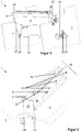
- FIG. 2 shows the fleece winder 1 in greater detail.
- Two housing parts 21, 30 thereby form a housing which is arranged rotatably about an axis at both ends by means of pivoting parts 22 arranged here at both ends, which axis coincides with the axis of rotation of the contact roller 8.
- a respective drive unit is preferably arranged on both frame walls 7 on their outer sides.
- this includes an electric motor 26 which is rotationally connected to a drive wheel 24 by means of a gear 27.
- Each drive wheel 24 is rotationally connected to an associated pivoting part 22 via a belt 23.
- the drive wheels 24 of both drive units are preferably rotationally connected to one another via a connecting shaft 25.
- only one motor 26 could be sufficient to drive both drive wheels 24.
- the drive units are preferably attached to the associated frame wall 7 by means of a respective fastening part 28.
- the assembly 21, 22, 30 only rotates in one direction, namely clockwise according to FIG Figure 2 .
- Figure 3 shows the fleece winder 1 within the framework of the separating section 20, enlarged in the cutout.
- the housing part 30 has on the front side here preferably a plurality of through openings 31. Furthermore, the entire housing 21, 22, 30 has an opening on the side pointing upwards here, which in the example shown is formed by means of a recess 32 in the housing part 30.
- blow nozzles 51 are provided, only one of which is visible here. These are arranged in such a way that they can allow air to pass through the respective opening 31 to the outside with respect to the housing 21, 22, 30.
- Figure 4 shows the separating section 20 with the housing partially open.
- the housing part 30 is missing as an example.
- the cutting elements 46 of a cutting cut 40 are arranged on a shaft 42, the axis of rotation of which coincides with the axis of rotation of the contact roller 8, not shown here.
- Figure 4 shows the cutting section 40 in the folded-in position, in which it is not possible for the cutting elements 46 to separate a fleece by means of their cutting edges 41.
- the cutting elements 46 are located in the interior of the housing 21, 22, 30.
- a blow section 50 is accommodated in the housing 21, 22, 30. This comprises several blowing elements 51, which make it possible to let air out here towards the front.
- the blowing elements 51 are preferably arranged in a rotationally fixed manner on a shaft 52.
- the shaft 52 is advantageously adjustable on the housing 21, 22, 30 and is rotatably supported here on the pivot part 22.
- the shaft 22 is mounted on at least one bearing section 14 which is attached in the housing 21, 22, 30 in order to prevent the shaft 22 from bending.
- the pivoting part 22 is preferably fastened to the output gear 29 and also forms a one-sided limit on the left side for the belt 23 looped around the output gear 29.
- the pivoting part 22 can also be designed in one piece with the output gear 29.
- the shaft 42 with the cutting elements 46 non-rotatably arranged thereon also comprises a pivot lever 44, which in turn is non-rotatably arranged on the shaft 42. Furthermore, a fastening element 45 is shown on the right-hand side which rotatably accommodates the shaft 42 on the pivot part 22.
- FIG. 13 shows the internal structure of the partition portion 20 from the one in FIG Figure 4 opposite, left end. Both housing parts 21, 30 are missing here.
- the shaft 42 is preferably only rotatably received by the fastening element 45, specifically via a pivot bearing 48.
- the shaft 42 can of course also be supported by means of the pivoting part 22, not shown here.
- the cutting elements 46 are fastened to the shaft 42 by means of fastening elements 47.
- a free end of the pivot lever 44 is connected via a pivot bearing 49 to a free end of a piston, not designated, of a pneumatic cylinder 43. It is thus possible for the pneumatic cylinder 43 to pivot the pivot lever 44 counterclockwise here by retracting its piston and thus pivot the cutting elements 46 upwards in the same direction around the axis of rotation 42. Thus, the cutting edge 41 of the respective cutting element 46 according to FIG. 2 protrudes from the recess 32 upward out of the housing 21, 22, 30. This makes it possible to separate a fleece arranged above it.
- the blower element 51 is attached by way of example by means of fastening elements 57 to a fastening part 55, which in turn is arranged non-rotatably on the shaft 52 via fastening elements 56.
- an adjusting screw 13 is shown here floating freely. Actually, it is screwed into the pivoting part 22 (not shown here) and with its end facing the shaft 52 it clamps in the pivoting part 22.
- the pivot part 22 has a continuous opening so that the screw 13 is accessible from the outside with a screwing tool. It is thus possible to lock the shaft 52 in any rotational position.
- the blower elements 51 attached to the shaft 52 can thus be aligned in their position with respect to their nozzles 53.
- air introduced into the respective blower element 51 via a connection 54 is blown out via the blower nozzles 53 in a direction which includes an acute angle to the folded-in position of the cutting elements 46 shown here.
- This enables the fleece arranged below the respective cutting edge 41 to be moved in the direction of the winding shaft to be wound.
- FIG. 11 shows a method for operating the fleece winder 1.
- a subsequent step S2 checks whether there is a winding shaft change, that is to say whether or not a fleece is to be separated.
- step S2 If this is not the case (no branch after step S2), a jump is made back to step S2.
- step S2 the separation of the fleece is initiated in a step S10.
- step S3 the separated partial fleece intended for the new winding shaft is conveyed in a step S3 by means of the blow section 50 in the direction of the new winding shaft.
- step S10 dashed line
- step S3 dashed line
- step S2 a jump back to step S2 is made.
- Figure 7 shows the process of separating the fleece in step S10 in greater detail.
- a first step S11 the separating section 20 is rotated into the separating position by means of rotation, specifically by means of the motor 26.
- the separating section 20 is advantageously moved out of the separating position (i.e. pivoted or rotated) so that the fleece winder 1 or the new winding shaft is or are not hindered in the course of the winding process.
- step S10 The process in step S10 is then ended.
- the cutting elements 46 In addition or as an alternative to the folding mechanism for the cutting elements 46, provision can also be made for the cutting elements 46 to be operated in an oscillating manner.
- a link guide is the solution. In this setting, the cutting elements 46 are oscillated in and out of the housing 21, 22, 30 and / or transversely to this direction of movement.
- a conventional, rotating cutting knife can also be provided, which moves along the axis of rotation of the contact roller 8 and thereby rotates about an axis which runs perpendicular to the axis of rotation of the contact roller 8 and is arranged so that the plane of rotation of the cutting knife is parallel to the travel of the cutting knife.
- steps S11 and S14 can be omitted.
- the preceding explanations can also have a sensor system which is set up to detect when the separating section 20 is in the separating mode, that is to say when the fleece is currently being separated.
- the sensor system can have a pneumatic sensor. This enables the coupling to an evaluation circuit arranged externally in relation to the separating section, even if this means signal transmission from a stationary part (for example the frame wall 7) and a movable part (for example the housing 21, 22, 30).
- this is preferably connected to a signal converter outside the separating section 20, which converts the sensor signal of the pneumatic sensor into an electrical signal and is coupled to a corresponding control circuit. This makes it possible to continue to use electrical control circuits.
- the tips of the cutting edges 41 can be replaced by any other contour or combined with one that enables the nonwoven to be separated.
- pneumatic drive pneumatic cylinder 43
- electric motor drive can also be provided.
- the belt 23 can of course be replaced by any other traction means such as a chain.
- the invention creates a simple but safe device for separating fleece, which can be easily integrated into fleece winder and also enables a very simple operating method.
Landscapes
- Engineering & Computer Science (AREA)
- Textile Engineering (AREA)
- Replacement Of Web Rolls (AREA)
Priority Applications (1)
| Application Number | Priority Date | Filing Date | Title |
|---|---|---|---|
| PL18171167T PL3409818T3 (pl) | 2017-05-24 | 2018-05-08 | Urządzenie tnące dla nawijarki do włókniny i odnośny sposób |
Applications Claiming Priority (1)
| Application Number | Priority Date | Filing Date | Title |
|---|---|---|---|
| DE102017111365.7A DE102017111365B4 (de) | 2017-05-24 | 2017-05-24 | Schneidvorrichtung für einen Vlieswickler und Verfahren dazu |
Publications (2)
| Publication Number | Publication Date |
|---|---|
| EP3409818A1 EP3409818A1 (de) | 2018-12-05 |
| EP3409818B1 true EP3409818B1 (de) | 2021-07-07 |
Family
ID=62142968
Family Applications (1)
| Application Number | Title | Priority Date | Filing Date |
|---|---|---|---|
| EP18171167.2A Active EP3409818B1 (de) | 2017-05-24 | 2018-05-08 | Schneidvorrichtung für einen vlieswickler und verfahren dazu |
Country Status (4)
| Country | Link |
|---|---|
| EP (1) | EP3409818B1 (pl) |
| CN (1) | CN108928661B (pl) |
| DE (1) | DE102017111365B4 (pl) |
| PL (1) | PL3409818T3 (pl) |
Families Citing this family (2)
| Publication number | Priority date | Publication date | Assignee | Title |
|---|---|---|---|---|
| CN117163715B (zh) * | 2023-09-26 | 2025-12-26 | 泉州立成机械有限公司 | 一种自动卷布机及其卷布方法 |
| CN119240391B (zh) * | 2024-12-04 | 2025-04-04 | 浙江佑威新材料股份有限公司 | 膜卷恒力自动收卷装置 |
Citations (2)
| Publication number | Priority date | Publication date | Assignee | Title |
|---|---|---|---|---|
| WO1995015901A1 (en) * | 1993-12-08 | 1995-06-15 | Beloit Technologies, Inc. | Method and apparatus for effecting a set change in a paper winder |
| EP0698571A2 (de) * | 1994-08-17 | 1996-02-28 | Klaus Reinhold | Schneid- und Transportwalze für Materialbahnen |
Family Cites Families (18)
| Publication number | Priority date | Publication date | Assignee | Title |
|---|---|---|---|---|
| DE1057922B (de) | 1956-01-19 | 1959-05-21 | Spinnerei Karl Marx Veb | Trenn- und Anlegevorrichtung fuer Vlieswickler |
| DE1574426B1 (de) * | 1967-12-22 | 1972-01-20 | Reifenhaeuser Kg | Wickelmaschine zum Aufwickeln von kontinuierlich erzeugten Warenbahnen |
| US3610545A (en) * | 1969-01-17 | 1971-10-05 | Reifenhauser Kg Maschinenfabri | Apparatus for winding continuously produced layer material on elongated core |
| JPS61130164A (ja) * | 1984-11-30 | 1986-06-18 | Mitsubishi Heavy Ind Ltd | フイルム等帯状物の自動切断巻取装置 |
| EP0237903B1 (en) * | 1986-03-17 | 1989-10-25 | Mitsubishi Jukogyo Kabushiki Kaisha | Automatic cutting and winding apparatus for a web-like material such as a film |
| US5464166A (en) * | 1994-08-26 | 1995-11-07 | E. I. Du Pont De Nemours And Company | Method and apparatus for automatic roll transfer |
| IT1289169B1 (it) * | 1997-01-10 | 1998-09-29 | Italconverting Srl | Macchina e metodo per la produzione di rotoli o logs di materiali in foglio |
| EP0957054A1 (de) * | 1998-03-16 | 1999-11-17 | Voith Sulzer Papiertechnik Patent GmbH | Wickelmaschine und Verfahren zum Aufwickeln einer Materialbahn |
| DE50209251D1 (de) * | 2002-10-25 | 2007-02-22 | Reifenhaeuser Masch | Wickeleinrichtung sowie Verfahren zur Durchführung eines Wickelhülsenwechsels in einer Wickeleinrichtung |
| WO2007096918A1 (en) * | 2006-02-27 | 2007-08-30 | A. Celli Nonwovens S.P.A. | Machine for the production of reels with a cutting system set upstream of the winding member |
| CN201254407Y (zh) * | 2008-08-22 | 2009-06-10 | 晟弘制机工业有限公司 | 复卷机 |
| CN201525975U (zh) * | 2009-09-21 | 2010-07-14 | 邵阳纺织机械有限责任公司 | 适用于非织造布分切机的电气控制装置 |
| IT1401881B1 (it) * | 2010-09-28 | 2013-08-28 | Perini Fabio Spa | Macchina ribobinatrice e metodo per la produzione di rotoli di materiale nastriforme |
| EP2838825B1 (en) * | 2012-04-18 | 2018-08-01 | Jesco Holding ApS | Winding apparatus for winding a web into a roll |
| CN202542537U (zh) * | 2012-04-25 | 2012-11-21 | 深圳市嘉拓自动化技术有限公司 | 一种自动换卷放卷机 |
| JP5976043B2 (ja) * | 2014-06-12 | 2016-08-23 | 株式会社豊岡製作所 | ウエブ切断装置 |
| CN205709043U (zh) * | 2016-01-21 | 2016-11-23 | 佛山市宝索机械制造有限公司 | 复卷机的断纸机构 |
| CN205616305U (zh) * | 2016-04-20 | 2016-10-05 | 常州市展明薄膜科技有限公司 | 离型膜自动切割装置 |
-
2017
- 2017-05-24 DE DE102017111365.7A patent/DE102017111365B4/de active Active
-
2018
- 2018-05-08 PL PL18171167T patent/PL3409818T3/pl unknown
- 2018-05-08 EP EP18171167.2A patent/EP3409818B1/de active Active
- 2018-05-21 CN CN201810491250.8A patent/CN108928661B/zh active Active
Patent Citations (2)
| Publication number | Priority date | Publication date | Assignee | Title |
|---|---|---|---|---|
| WO1995015901A1 (en) * | 1993-12-08 | 1995-06-15 | Beloit Technologies, Inc. | Method and apparatus for effecting a set change in a paper winder |
| EP0698571A2 (de) * | 1994-08-17 | 1996-02-28 | Klaus Reinhold | Schneid- und Transportwalze für Materialbahnen |
Also Published As
| Publication number | Publication date |
|---|---|
| DE102017111365A1 (de) | 2018-11-29 |
| CN108928661B (zh) | 2020-10-02 |
| CN108928661A (zh) | 2018-12-04 |
| EP3409818A1 (de) | 2018-12-05 |
| PL3409818T3 (pl) | 2021-10-25 |
| DE102017111365B4 (de) | 2021-08-12 |
Similar Documents
| Publication | Publication Date | Title |
|---|---|---|
| EP3603948B1 (de) | Anlage zur herstellung von wellpappe | |
| DE4213712C2 (de) | Kontaktwabenwickelmaschine zum rechts- und linksdrehenden Aufwickeln einer bahnförmigen Kunststoffolie | |
| EP3406770B1 (de) | Schneidvorrichtung für einen vlieswickler | |
| EP3409818B1 (de) | Schneidvorrichtung für einen vlieswickler und verfahren dazu | |
| DE2600522A1 (de) | Wickelmaschine | |
| DE19857507A1 (de) | Falzapparat für Rotationsdruckmaschinen | |
| EP0931748B1 (de) | Punkturloser Falzapparat für Rotationsdruckmaschinen | |
| DE3914178C2 (pl) | ||
| DE2911268C2 (de) | Vorrichtung zum ununterbrochenen Abwickeln von Warenbahnen | |
| EP0581102B1 (de) | Einrichtung zum Übernehmen von Blattmaterial und zum Übergeben des Blattmaterials an eine Entnahmestation | |
| DE10058458B4 (de) | Vorrichtung zum Verbinden zweier Materialbahnen | |
| EP0693377B1 (de) | Vorrichtung zum Quertrennen einer Papierbahn | |
| EP0618160A2 (de) | Papierrolle, Papierrollenauspackstation und Verfahren zum Auspacken einer Papierrolle | |
| DE102008041564B3 (de) | Rollenwechsler mit einer Vorrichtung zum kontrollierten Auffangen und Aufwickeln einer Restfahne einer abgelaufenen Materialrolle beim fliegenden Rollenwechsel | |
| DE10331755C5 (de) | Schutzeinrichtung am Ausleger | |
| AT522407B1 (de) | Ausgabevorrichtung zur Ausgabe eines bahnförmigen Flächenproduktes | |
| EP1657198B1 (de) | Verfahren und Vorrichtung zum Kappen und/oder Zuführen eines Stranges in eine Weiterverarbeitungsstufe sowie Strangverarbeitungssystem | |
| EP0734988A2 (de) | Verfahren und Einrichtung zum Bewegen von Punkturnadeln | |
| EP1732833B1 (de) | Verfahren und vorrichtungen zum kappen und/oder zuführen eines stranges in eine weiterverarbeitungsstufe | |
| WO2002102594A1 (de) | Verfahren und einrichtung zum einziehen einer materialbahn | |
| EP1726548B1 (de) | Verfahren und eine Vorrichtung zum Regeln einer Bahnspannung einer laufenden Bahn in einer bahnverarbeitenden Vorrichtung | |
| DE10058437B4 (de) | Vorrichtungen zum Verbinden zweier Materialbahnen | |
| EP3261967B1 (de) | Vorrichtung und verfahren zum handhaben eines aufgehaspelten fadenstrangs | |
| DE10058436B4 (de) | Vorrichtungen zum Verbinden zweier Materialbahnen | |
| EP1683752A1 (de) | Vorrichtung zum Querschneiden einer Materialbahn in einzelne Materialabschnitte |
Legal Events
| Date | Code | Title | Description |
|---|---|---|---|
| PUAI | Public reference made under article 153(3) epc to a published international application that has entered the european phase |
Free format text: ORIGINAL CODE: 0009012 |
|
| STAA | Information on the status of an ep patent application or granted ep patent |
Free format text: STATUS: REQUEST FOR EXAMINATION WAS MADE |
|
| 17P | Request for examination filed |
Effective date: 20180508 |
|
| AK | Designated contracting states |
Kind code of ref document: A1 Designated state(s): AL AT BE BG CH CY CZ DE DK EE ES FI FR GB GR HR HU IE IS IT LI LT LU LV MC MK MT NL NO PL PT RO RS SE SI SK SM TR |
|
| AX | Request for extension of the european patent |
Extension state: BA ME |
|
| STAA | Information on the status of an ep patent application or granted ep patent |
Free format text: STATUS: EXAMINATION IS IN PROGRESS |
|
| 17Q | First examination report despatched |
Effective date: 20190123 |
|
| RBV | Designated contracting states (corrected) |
Designated state(s): AL AT BE BG CH CY CZ DE DK EE ES FI FR GB GR HR HU IE IS IT LI LT LU LV MC MK MT NL NO PL PT RO RS SE SI SK SM TR |
|
| RIC1 | Information provided on ipc code assigned before grant |
Ipc: B65H 19/28 20060101ALI20200615BHEP Ipc: B65H 19/26 20060101ALI20200615BHEP Ipc: D01G 27/00 20060101AFI20200615BHEP |
|
| GRAP | Despatch of communication of intention to grant a patent |
Free format text: ORIGINAL CODE: EPIDOSNIGR1 |
|
| STAA | Information on the status of an ep patent application or granted ep patent |
Free format text: STATUS: GRANT OF PATENT IS INTENDED |
|
| INTG | Intention to grant announced |
Effective date: 20210225 |
|
| GRAS | Grant fee paid |
Free format text: ORIGINAL CODE: EPIDOSNIGR3 |
|
| GRAA | (expected) grant |
Free format text: ORIGINAL CODE: 0009210 |
|
| STAA | Information on the status of an ep patent application or granted ep patent |
Free format text: STATUS: THE PATENT HAS BEEN GRANTED |
|
| AK | Designated contracting states |
Kind code of ref document: B1 Designated state(s): AL AT BE BG CH CY CZ DE DK EE ES FI FR GB GR HR HU IE IS IT LI LT LU LV MC MK MT NL NO PL PT RO RS SE SI SK SM TR |
|
| REG | Reference to a national code |
Ref country code: GB Ref legal event code: FG4D Free format text: NOT ENGLISH |
|
| REG | Reference to a national code |
Ref country code: AT Ref legal event code: REF Ref document number: 1408697 Country of ref document: AT Kind code of ref document: T Effective date: 20210715 |
|
| REG | Reference to a national code |
Ref country code: DE Ref legal event code: R096 Ref document number: 502018005974 Country of ref document: DE |
|
| REG | Reference to a national code |
Ref country code: IE Ref legal event code: FG4D Free format text: LANGUAGE OF EP DOCUMENT: GERMAN |
|
| REG | Reference to a national code |
Ref country code: LT Ref legal event code: MG9D |
|
| REG | Reference to a national code |
Ref country code: NL Ref legal event code: MP Effective date: 20210707 |
|
| PG25 | Lapsed in a contracting state [announced via postgrant information from national office to epo] |
Ref country code: SE Free format text: LAPSE BECAUSE OF FAILURE TO SUBMIT A TRANSLATION OF THE DESCRIPTION OR TO PAY THE FEE WITHIN THE PRESCRIBED TIME-LIMIT Effective date: 20210707 Ref country code: RS Free format text: LAPSE BECAUSE OF FAILURE TO SUBMIT A TRANSLATION OF THE DESCRIPTION OR TO PAY THE FEE WITHIN THE PRESCRIBED TIME-LIMIT Effective date: 20210707 Ref country code: HR Free format text: LAPSE BECAUSE OF FAILURE TO SUBMIT A TRANSLATION OF THE DESCRIPTION OR TO PAY THE FEE WITHIN THE PRESCRIBED TIME-LIMIT Effective date: 20210707 Ref country code: ES Free format text: LAPSE BECAUSE OF FAILURE TO SUBMIT A TRANSLATION OF THE DESCRIPTION OR TO PAY THE FEE WITHIN THE PRESCRIBED TIME-LIMIT Effective date: 20210707 Ref country code: FI Free format text: LAPSE BECAUSE OF FAILURE TO SUBMIT A TRANSLATION OF THE DESCRIPTION OR TO PAY THE FEE WITHIN THE PRESCRIBED TIME-LIMIT Effective date: 20210707 Ref country code: NL Free format text: LAPSE BECAUSE OF FAILURE TO SUBMIT A TRANSLATION OF THE DESCRIPTION OR TO PAY THE FEE WITHIN THE PRESCRIBED TIME-LIMIT Effective date: 20210707 Ref country code: NO Free format text: LAPSE BECAUSE OF FAILURE TO SUBMIT A TRANSLATION OF THE DESCRIPTION OR TO PAY THE FEE WITHIN THE PRESCRIBED TIME-LIMIT Effective date: 20211007 Ref country code: PT Free format text: LAPSE BECAUSE OF FAILURE TO SUBMIT A TRANSLATION OF THE DESCRIPTION OR TO PAY THE FEE WITHIN THE PRESCRIBED TIME-LIMIT Effective date: 20211108 Ref country code: LT Free format text: LAPSE BECAUSE OF FAILURE TO SUBMIT A TRANSLATION OF THE DESCRIPTION OR TO PAY THE FEE WITHIN THE PRESCRIBED TIME-LIMIT Effective date: 20210707 Ref country code: BG Free format text: LAPSE BECAUSE OF FAILURE TO SUBMIT A TRANSLATION OF THE DESCRIPTION OR TO PAY THE FEE WITHIN THE PRESCRIBED TIME-LIMIT Effective date: 20211007 |
|
| PG25 | Lapsed in a contracting state [announced via postgrant information from national office to epo] |
Ref country code: LV Free format text: LAPSE BECAUSE OF FAILURE TO SUBMIT A TRANSLATION OF THE DESCRIPTION OR TO PAY THE FEE WITHIN THE PRESCRIBED TIME-LIMIT Effective date: 20210707 Ref country code: GR Free format text: LAPSE BECAUSE OF FAILURE TO SUBMIT A TRANSLATION OF THE DESCRIPTION OR TO PAY THE FEE WITHIN THE PRESCRIBED TIME-LIMIT Effective date: 20211008 |
|
| REG | Reference to a national code |
Ref country code: LU Ref legal event code: PD Owner name: TRUETZSCHLER GROUP SE; DE Free format text: FORMER OWNER: TRUETZSCHLER GMBH & CO. KG Effective date: 20220309 |
|
| REG | Reference to a national code |
Ref country code: DE Ref legal event code: R097 Ref document number: 502018005974 Country of ref document: DE |
|
| PG25 | Lapsed in a contracting state [announced via postgrant information from national office to epo] |
Ref country code: DK Free format text: LAPSE BECAUSE OF FAILURE TO SUBMIT A TRANSLATION OF THE DESCRIPTION OR TO PAY THE FEE WITHIN THE PRESCRIBED TIME-LIMIT Effective date: 20210707 |
|
| PLBE | No opposition filed within time limit |
Free format text: ORIGINAL CODE: 0009261 |
|
| STAA | Information on the status of an ep patent application or granted ep patent |
Free format text: STATUS: NO OPPOSITION FILED WITHIN TIME LIMIT |
|
| PG25 | Lapsed in a contracting state [announced via postgrant information from national office to epo] |
Ref country code: SM Free format text: LAPSE BECAUSE OF FAILURE TO SUBMIT A TRANSLATION OF THE DESCRIPTION OR TO PAY THE FEE WITHIN THE PRESCRIBED TIME-LIMIT Effective date: 20210707 Ref country code: SK Free format text: LAPSE BECAUSE OF FAILURE TO SUBMIT A TRANSLATION OF THE DESCRIPTION OR TO PAY THE FEE WITHIN THE PRESCRIBED TIME-LIMIT Effective date: 20210707 Ref country code: RO Free format text: LAPSE BECAUSE OF FAILURE TO SUBMIT A TRANSLATION OF THE DESCRIPTION OR TO PAY THE FEE WITHIN THE PRESCRIBED TIME-LIMIT Effective date: 20210707 Ref country code: EE Free format text: LAPSE BECAUSE OF FAILURE TO SUBMIT A TRANSLATION OF THE DESCRIPTION OR TO PAY THE FEE WITHIN THE PRESCRIBED TIME-LIMIT Effective date: 20210707 Ref country code: CZ Free format text: LAPSE BECAUSE OF FAILURE TO SUBMIT A TRANSLATION OF THE DESCRIPTION OR TO PAY THE FEE WITHIN THE PRESCRIBED TIME-LIMIT Effective date: 20210707 Ref country code: AL Free format text: LAPSE BECAUSE OF FAILURE TO SUBMIT A TRANSLATION OF THE DESCRIPTION OR TO PAY THE FEE WITHIN THE PRESCRIBED TIME-LIMIT Effective date: 20210707 |
|
| 26N | No opposition filed |
Effective date: 20220408 |
|
| REG | Reference to a national code |
Ref country code: DE Ref legal event code: R081 Ref document number: 502018005974 Country of ref document: DE Owner name: TRUETZSCHLER GROUP SE, DE Free format text: FORMER OWNER: TRUETZSCHLER GMBH & CO KOMMANDITGESELLSCHAFT, 41199 MOENCHENGLADBACH, DE |
|
| REG | Reference to a national code |
Ref country code: CH Ref legal event code: PL |
|
| REG | Reference to a national code |
Ref country code: BE Ref legal event code: MM Effective date: 20220531 |
|
| GBPC | Gb: european patent ceased through non-payment of renewal fee |
Effective date: 20220508 |
|
| PG25 | Lapsed in a contracting state [announced via postgrant information from national office to epo] |
Ref country code: MC Free format text: LAPSE BECAUSE OF FAILURE TO SUBMIT A TRANSLATION OF THE DESCRIPTION OR TO PAY THE FEE WITHIN THE PRESCRIBED TIME-LIMIT Effective date: 20210707 Ref country code: LI Free format text: LAPSE BECAUSE OF NON-PAYMENT OF DUE FEES Effective date: 20220531 Ref country code: CH Free format text: LAPSE BECAUSE OF NON-PAYMENT OF DUE FEES Effective date: 20220531 |
|
| PG25 | Lapsed in a contracting state [announced via postgrant information from national office to epo] |
Ref country code: IE Free format text: LAPSE BECAUSE OF NON-PAYMENT OF DUE FEES Effective date: 20220508 |
|
| PG25 | Lapsed in a contracting state [announced via postgrant information from national office to epo] |
Ref country code: GB Free format text: LAPSE BECAUSE OF NON-PAYMENT OF DUE FEES Effective date: 20220508 Ref country code: BE Free format text: LAPSE BECAUSE OF NON-PAYMENT OF DUE FEES Effective date: 20220531 |
|
| P01 | Opt-out of the competence of the unified patent court (upc) registered |
Effective date: 20230622 |
|
| PG25 | Lapsed in a contracting state [announced via postgrant information from national office to epo] |
Ref country code: HU Free format text: LAPSE BECAUSE OF FAILURE TO SUBMIT A TRANSLATION OF THE DESCRIPTION OR TO PAY THE FEE WITHIN THE PRESCRIBED TIME-LIMIT; INVALID AB INITIO Effective date: 20180508 |
|
| PG25 | Lapsed in a contracting state [announced via postgrant information from national office to epo] |
Ref country code: MK Free format text: LAPSE BECAUSE OF FAILURE TO SUBMIT A TRANSLATION OF THE DESCRIPTION OR TO PAY THE FEE WITHIN THE PRESCRIBED TIME-LIMIT Effective date: 20210707 Ref country code: CY Free format text: LAPSE BECAUSE OF FAILURE TO SUBMIT A TRANSLATION OF THE DESCRIPTION OR TO PAY THE FEE WITHIN THE PRESCRIBED TIME-LIMIT Effective date: 20210707 |
|
| REG | Reference to a national code |
Ref country code: AT Ref legal event code: MM01 Ref document number: 1408697 Country of ref document: AT Kind code of ref document: T Effective date: 20230508 |
|
| PG25 | Lapsed in a contracting state [announced via postgrant information from national office to epo] |
Ref country code: AT Free format text: LAPSE BECAUSE OF NON-PAYMENT OF DUE FEES Effective date: 20230508 |
|
| PG25 | Lapsed in a contracting state [announced via postgrant information from national office to epo] |
Ref country code: AT Free format text: LAPSE BECAUSE OF NON-PAYMENT OF DUE FEES Effective date: 20230508 |
|
| PG25 | Lapsed in a contracting state [announced via postgrant information from national office to epo] |
Ref country code: MT Free format text: LAPSE BECAUSE OF FAILURE TO SUBMIT A TRANSLATION OF THE DESCRIPTION OR TO PAY THE FEE WITHIN THE PRESCRIBED TIME-LIMIT Effective date: 20210707 |
|
| PGFP | Annual fee paid to national office [announced via postgrant information from national office to epo] |
Ref country code: DE Payment date: 20250521 Year of fee payment: 8 Ref country code: PL Payment date: 20250425 Year of fee payment: 8 |
|
| PGFP | Annual fee paid to national office [announced via postgrant information from national office to epo] |
Ref country code: LU Payment date: 20250521 Year of fee payment: 8 Ref country code: IT Payment date: 20250527 Year of fee payment: 8 |
|
| PGFP | Annual fee paid to national office [announced via postgrant information from national office to epo] |
Ref country code: FR Payment date: 20250528 Year of fee payment: 8 |
|
| PG25 | Lapsed in a contracting state [announced via postgrant information from national office to epo] |
Ref country code: TR Free format text: LAPSE BECAUSE OF FAILURE TO SUBMIT A TRANSLATION OF THE DESCRIPTION OR TO PAY THE FEE WITHIN THE PRESCRIBED TIME-LIMIT Effective date: 20210707 |
|
| PGFP | Annual fee paid to national office [announced via postgrant information from national office to epo] |
Ref country code: AT Payment date: 20260410 Year of fee payment: 5 |