EP3409818B1 - Schneidvorrichtung für einen vlieswickler und verfahren dazu - Google Patents
Schneidvorrichtung für einen vlieswickler und verfahren dazu Download PDFInfo
- Publication number
- EP3409818B1 EP3409818B1 EP18171167.2A EP18171167A EP3409818B1 EP 3409818 B1 EP3409818 B1 EP 3409818B1 EP 18171167 A EP18171167 A EP 18171167A EP 3409818 B1 EP3409818 B1 EP 3409818B1
- Authority
- EP
- European Patent Office
- Prior art keywords
- web
- section
- severing
- cutting
- winding shaft
- Prior art date
- Legal status (The legal status is an assumption and is not a legal conclusion. Google has not performed a legal analysis and makes no representation as to the accuracy of the status listed.)
- Active
Links
- 238000000034 method Methods 0.000 title claims description 27
- 239000004745 nonwoven fabric Substances 0.000 title 1
- 238000004804 winding Methods 0.000 claims description 76
- 230000003213 activating effect Effects 0.000 claims 2
- 238000000926 separation method Methods 0.000 description 12
- 230000008569 process Effects 0.000 description 8
- 208000027418 Wounds and injury Diseases 0.000 description 7
- 238000007664 blowing Methods 0.000 description 5
- 230000008901 benefit Effects 0.000 description 3
- 230000005540 biological transmission Effects 0.000 description 3
- 230000008859 change Effects 0.000 description 3
- 239000000463 material Substances 0.000 description 3
- 230000004913 activation Effects 0.000 description 2
- 230000001154 acute effect Effects 0.000 description 2
- 239000000853 adhesive Substances 0.000 description 1
- 230000001070 adhesive effect Effects 0.000 description 1
- 239000012790 adhesive layer Substances 0.000 description 1
- 238000005452 bending Methods 0.000 description 1
- 239000000470 constituent Substances 0.000 description 1
- 238000010276 construction Methods 0.000 description 1
- 230000008878 coupling Effects 0.000 description 1
- 238000010168 coupling process Methods 0.000 description 1
- 238000005859 coupling reaction Methods 0.000 description 1
- 230000006378 damage Effects 0.000 description 1
- 238000011161 development Methods 0.000 description 1
- 230000018109 developmental process Effects 0.000 description 1
- 238000011156 evaluation Methods 0.000 description 1
- 238000007667 floating Methods 0.000 description 1
- 208000014674 injury Diseases 0.000 description 1
- 230000007246 mechanism Effects 0.000 description 1
- 238000011017 operating method Methods 0.000 description 1
- 238000005192 partition Methods 0.000 description 1
- 230000008054 signal transmission Effects 0.000 description 1
- 238000012546 transfer Methods 0.000 description 1
Images


Classifications
-
- D—TEXTILES; PAPER
- D01—NATURAL OR MAN-MADE THREADS OR FIBRES; SPINNING
- D01G—PRELIMINARY TREATMENT OF FIBRES, e.g. FOR SPINNING
- D01G27/00—Lap- or sliver-winding devices, e.g. for products of cotton scutchers, jute cards, or worsted gill boxes
-
- B—PERFORMING OPERATIONS; TRANSPORTING
- B65—CONVEYING; PACKING; STORING; HANDLING THIN OR FILAMENTARY MATERIAL
- B65H—HANDLING THIN OR FILAMENTARY MATERIAL, e.g. SHEETS, WEBS, CABLES
- B65H19/00—Changing the web roll
- B65H19/22—Changing the web roll in winding mechanisms or in connection with winding operations
- B65H19/26—Cutting-off the web running to the wound web roll
-
- B—PERFORMING OPERATIONS; TRANSPORTING
- B65—CONVEYING; PACKING; STORING; HANDLING THIN OR FILAMENTARY MATERIAL
- B65H—HANDLING THIN OR FILAMENTARY MATERIAL, e.g. SHEETS, WEBS, CABLES
- B65H19/00—Changing the web roll
- B65H19/22—Changing the web roll in winding mechanisms or in connection with winding operations
- B65H19/28—Attaching the leading end of the web to the replacement web-roll core or spindle
-
- D—TEXTILES; PAPER
- D01—NATURAL OR MAN-MADE THREADS OR FIBRES; SPINNING
- D01G—PRELIMINARY TREATMENT OF FIBRES, e.g. FOR SPINNING
- D01G21/00—Combinations of machines, apparatus, or processes, e.g. for continuous processing
-
- D—TEXTILES; PAPER
- D06—TREATMENT OF TEXTILES OR THE LIKE; LAUNDERING; FLEXIBLE MATERIALS NOT OTHERWISE PROVIDED FOR
- D06H—MARKING, INSPECTING, SEAMING OR SEVERING TEXTILE MATERIALS
- D06H7/00—Apparatus or processes for cutting, or otherwise severing, specially adapted for the cutting, or otherwise severing, of textile materials
-
- B—PERFORMING OPERATIONS; TRANSPORTING
- B65—CONVEYING; PACKING; STORING; HANDLING THIN OR FILAMENTARY MATERIAL
- B65H—HANDLING THIN OR FILAMENTARY MATERIAL, e.g. SHEETS, WEBS, CABLES
- B65H2301/00—Handling processes for sheets or webs
- B65H2301/40—Type of handling process
- B65H2301/41—Winding, unwinding
- B65H2301/414—Winding
- B65H2301/41419—Starting winding process
- B65H2301/41425—Starting winding process involving blowing means, e.g. air blast
-
- B—PERFORMING OPERATIONS; TRANSPORTING
- B65—CONVEYING; PACKING; STORING; HANDLING THIN OR FILAMENTARY MATERIAL
- B65H—HANDLING THIN OR FILAMENTARY MATERIAL, e.g. SHEETS, WEBS, CABLES
- B65H2701/00—Handled material; Storage means
- B65H2701/10—Handled articles or webs
- B65H2701/17—Nature of material
- B65H2701/177—Fibrous or compressible material
Definitions
- the invention relates to a cutting device for a web winder, a web winder equipped therewith and a method for the web winder provided with such a device.
- Fleece winder per se are known. They serve to wind a fleece coming out of a card, for example, onto a winding shaft. For this purpose, empty winding shafts are placed in a magazine of the fleece winder and gradually brought into a waiting position. The waiting position serves, on the one hand, to separate the winding shaft from the other winding shafts and, on the other hand, to set it in rotation from the beginning of the actual winding process.
- the fleece In order to end the winding of a winding shaft and to initiate the winding of a subsequent, empty winding shaft, the fleece must be separated. For this purpose, it is known to move a knife rotating transversely to the axis of rotation of a contact roller of the fleece winder along the axis of rotation of that very contact roller. This has several disadvantages. On the one hand, such a separation process tends to tear the fleece at certain points, so that it is unusable for further use after winding. On the other hand, the contact roller continues to rotate when the fleece is cut. This leads to a cutting pattern that includes an acute angle with respect to the direction of transport of the fleece, which increases the problem of unusable areas of the fleece. To address this problem, fold-out knives have been developed. However, there is the problem with both separation variants that the cut off Fleece does not get safely onto the empty winding shaft to be rewound, where it adheres to an adhesive surface, which is implemented, for example, by means of an adhesive layer.
- retractable cutting devices for the web of material can be used in the winding machine for the documents WO 96/06791 A1 , JP 2014 198632 A , WO 95/15901 A1 and EP 0 698 571 A2 already known.
- the object of the invention is therefore to create a device for a fleece winder which at least reduces the aforementioned disadvantages.
- a device which is designed to be integrated into a fleece winder in such a way that the fleece winder is able to separate a fleece at a predetermined position while it is being wound onto a first winding shaft and a partial fleece resulting from the separation, whose has the free end in the transport direction of the fleece to be conveyed against a second winding shaft arranged opposite to the transport direction.
- the device is able to actively convey the free end of the fleece in the direction of the empty winding shaft.
- the partial fleece is preferably conveyed by means of at least one blower nozzle of the device.
- the blower nozzle is connected to a compressed air connection and, when the fleece is separated, is arranged in such a way that compressed air coming from the compressed air connection emerges from the blower nozzle, essentially in the direction of the second winding shaft and against a predetermined area of the partial fleece in such a way that the partial fleece against the second winding shaft is blown.
- the separation is implemented by means of a cutting device of the device, which has a holding section. This is designed to be rotatably arranged on the web winder along a contact surface of a contact roller of the web winder in a direction of rotation of the contact roller.
- the cutting device further comprises a separating section with a cutting section which extends at least over a width of the fleece to be separated.
- the cutting section is fixed in relation to an axis of rotation of the contact roller or can be driven in an oscillating manner by means of a drive of the cutting device.
- the cutting device also comprises an actuating section. This is set up to accommodate the separating section in a first state in the holding section in such a way that the cutting device is prevented from coming into contact with the fleece.
- the cutting device therefore hardly poses a risk of injury to an operator.
- the actuating section is also set up, in a second state, to move the separating section essentially along a plane of rotation defined by means of the axis of rotation of the device, so that the cutting section is pushed against a side of the fleece facing the contact roller in such a way that the fleece is separated by means of the cutting section.
- I. E. only at the time of cutting is the cutting section brought into the second state corresponding to a cutting or cutting position. Moving along the plane of rotation enables the cutting device (or its knife section) to sever the fleece essentially parallel and not at an angle to the axis of rotation, which helps reduce the unusable material.
- the separating section preferably also has a second section. This extends essentially parallel to the cutting section.
- the cutting section has a contour that is designed in the second state to hold the fleece in the transport direction in relation to the holding section and / or to cut it due to its shape.
- a further step is necessary, for example by moving the cutting section away from the axis of rotation.
- holding is either not necessary or is done by the cutting section itself when the fleece is severed.
- the separating section is arranged in the holding section so as to be rotatable or movable.
- the actuating section is therefore designed to rotate or drive the separating section back and forth between the first and second states. This is a movement that is easy to automate, in particular since no other movements, for example along the axis of rotation of the contact roller, are required.
- the actuating section has a pneumatic cylinder. It is an inexpensive and easy to integrate drive means.
- the device according to the invention preferably also has a sensor system. This is set up to detect the presence of at least one of the states of the separating section. This ensures that the blower nozzle is only activated when the cutting device is in the second state. It is therefore possible to operate the device according to the invention in a more controllable manner and, moreover, can be integrated very well into the operation of the fleece winder. Apart from that, no blown air and therefore no operating energy are wasted.
- the sensor system preferably has at least one sensor which is set up to be coupled to a control circuit of the fleece winder via a connecting section of the device.
- the connecting section comprises a pivot bearing and a fixed bearing.
- the fixed bearing has a connection which is accessible from the outside in relation to the fleece winder to connect a first sensor line. It also has an internal sensor line.
- the pivot bearing is designed to be stationary with respect to the holding section and rotatably mounted with respect to the fleece winder. It also has a second sensor line. This is designed to be coupled to the first sensor line for data transmission at one end in every rotational position and to be coupled for data transmission to the sensor at the other end. This makes it possible to bring the sensor directly into the vicinity of the cutting device in order to detect its current state. From the outside only the control of the web winder has to be connected.
- the at least one sensor is preferably formed by means of an electronically and / or pneumatically acting sensor.
- the sensor lines are accordingly of an electronic and / or pneumatic type.
- the electronic variant has the advantage of being able to process the sensor signal directly by means of the controller.
- a pneumatic sensor has the advantage of being able to transmit the signal using simple and inexpensive channels in the rotary and fixed bearing. Outside the arrangement there is also a signal converter that converts the pneumatic signal into a processable electrical signal.
- a fleece winder has one of the aforementioned devices and a drive.
- the drive is designed to bring the device from a waiting position into an operating position. After reaching the operating position, the drive is able to engage the first winding shaft Winding up the fleece by the fleece winder also having a rotatably driven contact roller.
- the fleece winder has a pressure element which is set up to press the first winding shaft against the contact roller. It is also set up to wind the fleece to be wound around a partial circumference of the contact roller due to the rotation of the first winding roll caused by friction between the contact roller and the rotation of the first winding roll on the first winding roll.
- the web winder is set up to use the device to separate the web and to convey the partial web in the direction of the second winding roll. A reliable change of the fleece from one winding shaft to the other can thus be achieved, and this with simple and inexpensive means.
- a method according to the invention for operating the aforementioned fleece winder has, according to the invention, a step of winding an incoming fleece around the first winding roll.
- the method has a step of detecting the presence of a separation state in which the fleece is to be separated. If this state of separation is detected, the method has a step of separating the fleece and, when the fleece has been separated or immediately after it has been separated, conveying the partial fleece in the direction of the second winding shaft.
- the invention therefore offers a very simple method for changing the fleece from one winding shaft to another.
- the device of the fleece winder is provided with at least one blowing nozzle, the partial fleece is transported or conveyed by applying compressed air to the at least one blowing nozzle. This is also very easy and inexpensive to implement.
- the method during or immediately after the conveying of the partial fleece, furthermore has a step of moving the separating section into the first state.
- the step of separating the fleece then comprises moving the separating section into the second state. This increases security and is also easy to implement.
- Each of the aforementioned methods can furthermore have a step of detecting the presence of an activation state in which the device is to be activated. If the activation state is present, the method further comprises a step of rotating the holding section into a separation position such that the fleece is guided around a surface of the holding section facing away from the contact roller. In addition, it is provided within the scope of the method that the holding section is rotated during or immediately after the conveying of the partial fleece out of the separating position, so that the fleece can freely move past the holding section.
- the step of separating the fleece can comprise a translatory back and forth movement of the cutting section along the axis of rotation of the holding section. This makes the separation of the fleece safer.
- Figure 1 shows a fleece winder 1 according to an embodiment of the invention.
- the constituents that are not essential to the invention are not explained further.
- the fleece winder 1 essentially comprises two frame walls 7, which are combined via unmarked connectors to form a frame which receives or holds all other functional elements of the fleece winder 1.
- the frame walls 7 have a magazine 2 in which there are unmarked winding shafts (here: two).
- the fleece winder 1 comprises a recess on each frame wall 7 which defines a waiting position 3 for a winding shaft. Since the winding shafts are held on both sides by a respective frame wall 7, a waiting position 3 is thus implemented by means of the two frame walls 7.
- the winding shaft arranged therein is set in rotation by means of a turning section 12.
- the turning section 12 makes contact with the area of the winding shaft which is used to receive fleece.
- a transport section 9 is provided.
- the fleece winder 1 has a start-up position 4 which is located in a kink area between the frame wall 7 and a contact roller 8.
- the contact roller 8 leads the incoming fleece to the winding shaft to be wound in a known manner.
- a separating section 20 is provided, which comprises a cutting section not further designated here.
- the fleece winder 1 has a winding position 5, which is implemented by means of a section between the frame wall 7 and the contact roller 8 arranged here on the left. In this position 5, the corresponding winding shaft, which has already picked up fleece in the winding-on position 4, is finally wound.
- a locking and movement section 10 is used to transport a respective winding shaft from the waiting position 3 via the initial winding position 4 to the winding position 5.
- the fleece is separated by means of the separating section 20, and the wound winding shaft is moved into an ejection position 6 of the fleece winder 1 by means of a winding and push-out section 11.
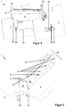
- FIG. 2 shows the fleece winder 1 in greater detail.
- Two housing parts 21, 30 thereby form a housing which is arranged rotatably about an axis at both ends by means of pivoting parts 22 arranged here at both ends, which axis coincides with the axis of rotation of the contact roller 8.
- a respective drive unit is preferably arranged on both frame walls 7 on their outer sides.
- this includes an electric motor 26 which is rotationally connected to a drive wheel 24 by means of a gear 27.
- Each drive wheel 24 is rotationally connected to an associated pivoting part 22 via a belt 23.
- the drive wheels 24 of both drive units are preferably rotationally connected to one another via a connecting shaft 25.
- only one motor 26 could be sufficient to drive both drive wheels 24.
- the drive units are preferably attached to the associated frame wall 7 by means of a respective fastening part 28.
- the assembly 21, 22, 30 only rotates in one direction, namely clockwise according to FIG Figure 2 .
- Figure 3 shows the fleece winder 1 within the framework of the separating section 20, enlarged in the cutout.
- the housing part 30 has on the front side here preferably a plurality of through openings 31. Furthermore, the entire housing 21, 22, 30 has an opening on the side pointing upwards here, which in the example shown is formed by means of a recess 32 in the housing part 30.
- blow nozzles 51 are provided, only one of which is visible here. These are arranged in such a way that they can allow air to pass through the respective opening 31 to the outside with respect to the housing 21, 22, 30.
- Figure 4 shows the separating section 20 with the housing partially open.
- the housing part 30 is missing as an example.
- the cutting elements 46 of a cutting cut 40 are arranged on a shaft 42, the axis of rotation of which coincides with the axis of rotation of the contact roller 8, not shown here.
- Figure 4 shows the cutting section 40 in the folded-in position, in which it is not possible for the cutting elements 46 to separate a fleece by means of their cutting edges 41.
- the cutting elements 46 are located in the interior of the housing 21, 22, 30.
- a blow section 50 is accommodated in the housing 21, 22, 30. This comprises several blowing elements 51, which make it possible to let air out here towards the front.
- the blowing elements 51 are preferably arranged in a rotationally fixed manner on a shaft 52.
- the shaft 52 is advantageously adjustable on the housing 21, 22, 30 and is rotatably supported here on the pivot part 22.
- the shaft 22 is mounted on at least one bearing section 14 which is attached in the housing 21, 22, 30 in order to prevent the shaft 22 from bending.
- the pivoting part 22 is preferably fastened to the output gear 29 and also forms a one-sided limit on the left side for the belt 23 looped around the output gear 29.
- the pivoting part 22 can also be designed in one piece with the output gear 29.
- the shaft 42 with the cutting elements 46 non-rotatably arranged thereon also comprises a pivot lever 44, which in turn is non-rotatably arranged on the shaft 42. Furthermore, a fastening element 45 is shown on the right-hand side which rotatably accommodates the shaft 42 on the pivot part 22.
- FIG. 13 shows the internal structure of the partition portion 20 from the one in FIG Figure 4 opposite, left end. Both housing parts 21, 30 are missing here.
- the shaft 42 is preferably only rotatably received by the fastening element 45, specifically via a pivot bearing 48.
- the shaft 42 can of course also be supported by means of the pivoting part 22, not shown here.
- the cutting elements 46 are fastened to the shaft 42 by means of fastening elements 47.
- a free end of the pivot lever 44 is connected via a pivot bearing 49 to a free end of a piston, not designated, of a pneumatic cylinder 43. It is thus possible for the pneumatic cylinder 43 to pivot the pivot lever 44 counterclockwise here by retracting its piston and thus pivot the cutting elements 46 upwards in the same direction around the axis of rotation 42. Thus, the cutting edge 41 of the respective cutting element 46 according to FIG. 2 protrudes from the recess 32 upward out of the housing 21, 22, 30. This makes it possible to separate a fleece arranged above it.
- the blower element 51 is attached by way of example by means of fastening elements 57 to a fastening part 55, which in turn is arranged non-rotatably on the shaft 52 via fastening elements 56.
- an adjusting screw 13 is shown here floating freely. Actually, it is screwed into the pivoting part 22 (not shown here) and with its end facing the shaft 52 it clamps in the pivoting part 22.
- the pivot part 22 has a continuous opening so that the screw 13 is accessible from the outside with a screwing tool. It is thus possible to lock the shaft 52 in any rotational position.
- the blower elements 51 attached to the shaft 52 can thus be aligned in their position with respect to their nozzles 53.
- air introduced into the respective blower element 51 via a connection 54 is blown out via the blower nozzles 53 in a direction which includes an acute angle to the folded-in position of the cutting elements 46 shown here.
- This enables the fleece arranged below the respective cutting edge 41 to be moved in the direction of the winding shaft to be wound.
- FIG. 11 shows a method for operating the fleece winder 1.
- a subsequent step S2 checks whether there is a winding shaft change, that is to say whether or not a fleece is to be separated.
- step S2 If this is not the case (no branch after step S2), a jump is made back to step S2.
- step S2 the separation of the fleece is initiated in a step S10.
- step S3 the separated partial fleece intended for the new winding shaft is conveyed in a step S3 by means of the blow section 50 in the direction of the new winding shaft.
- step S10 dashed line
- step S3 dashed line
- step S2 a jump back to step S2 is made.
- Figure 7 shows the process of separating the fleece in step S10 in greater detail.
- a first step S11 the separating section 20 is rotated into the separating position by means of rotation, specifically by means of the motor 26.
- the separating section 20 is advantageously moved out of the separating position (i.e. pivoted or rotated) so that the fleece winder 1 or the new winding shaft is or are not hindered in the course of the winding process.
- step S10 The process in step S10 is then ended.
- the cutting elements 46 In addition or as an alternative to the folding mechanism for the cutting elements 46, provision can also be made for the cutting elements 46 to be operated in an oscillating manner.
- a link guide is the solution. In this setting, the cutting elements 46 are oscillated in and out of the housing 21, 22, 30 and / or transversely to this direction of movement.
- a conventional, rotating cutting knife can also be provided, which moves along the axis of rotation of the contact roller 8 and thereby rotates about an axis which runs perpendicular to the axis of rotation of the contact roller 8 and is arranged so that the plane of rotation of the cutting knife is parallel to the travel of the cutting knife.
- steps S11 and S14 can be omitted.
- the preceding explanations can also have a sensor system which is set up to detect when the separating section 20 is in the separating mode, that is to say when the fleece is currently being separated.
- the sensor system can have a pneumatic sensor. This enables the coupling to an evaluation circuit arranged externally in relation to the separating section, even if this means signal transmission from a stationary part (for example the frame wall 7) and a movable part (for example the housing 21, 22, 30).
- this is preferably connected to a signal converter outside the separating section 20, which converts the sensor signal of the pneumatic sensor into an electrical signal and is coupled to a corresponding control circuit. This makes it possible to continue to use electrical control circuits.
- the tips of the cutting edges 41 can be replaced by any other contour or combined with one that enables the nonwoven to be separated.
- pneumatic drive pneumatic cylinder 43
- electric motor drive can also be provided.
- the belt 23 can of course be replaced by any other traction means such as a chain.
- the invention creates a simple but safe device for separating fleece, which can be easily integrated into fleece winder and also enables a very simple operating method.
Landscapes
- Engineering & Computer Science (AREA)
- Textile Engineering (AREA)
- Replacement Of Web Rolls (AREA)
Description
- Die Erfindung betrifft eine Schneidvorrichtung für einen Vlieswickler, einen damit ausgestatteten Vlieswickler und ein Verfahren für den mit solch einer Vorrichtung versehenen Vlieswickler.
- Vlieswickler an sich sind bekannt. Sie dienen dazu, ein beispielsweise aus einer Karde herauskommendes Vlies auf eine Wickelwelle aufzuwickeln. Dazu werden leere Wickelwellen in einem Magazin des Vlieswicklers eingelegt und nach und nach zunächst in eine Warteposition gebracht. Die Warteposition dient dazu, zum einen die Wickelwelle von den anderen Wickelwellen zu separieren und sie zum anderen von dem Beginn des eigentlichen Wickelvorgangs in Rotation zu versetzen.
- Um das Bewickeln einer Wickelwelle zu beenden und das Bewickeln einer nachfolgenden, leeren Wickelwelle einzuleiten, muss das Vlies getrennt werden. Dazu ist bekannt, ein quer zur Rotationsachse einer Kontaktwalze des Vlieswicklers rotierendes Messer entlang der Rotationsachse ebenjener Kontaktwalze zu verfahren. Dies hat mehrere Nachteile. Zum einen neigt solch ein Trennvorgang dazu, das Vlies an bestimmten Stellen zu zerreißen, sodass es für die weitere Verwendung nach dem Bewickeln unbrauchbar ist. Zum anderen dreht die Kontaktwalze beim Zerschneiden des Vlieses weiter. Dies führt zu einem Schneidbild, das in Bezug auf die Transportrichtung des Vlieses einen spitzen Winkel einschließt, was die Problematik der unbrauchbaren Bereiche des Vlieses erhöht. Um diesem Problem zu begegnen, wurden herausklappbare Messer entwickelt. Allerdings besteht bei beiden Trennvarianten das Problem, dass das abgeschnittene Vlies nicht sicher auf die leere, neu zu bewickelnde Wickelwelle gelangt, wo es auf einer adhäsiven Fläche, die beispielsweise mittels einer Klebeschicht realisiert ist, anhaftet.
- Bekannten Wickler für Warenbahnen, aufweisend einer Trennvorrichtung, der genannten Art werden in den Druckschriften
DE 1 5 74 426 B ,EP 0 853 060 A1 ,WO 2013/156036 A1 undEP 0 957 054 A1 beschrieben. - Ferner sind herausfahrbare Schneidevorrichtungen für Warenbahn in Wickelmaschine einsetzbar von den Dokumenten
WO 96/06791 A1 JP 2014 198632 A WO 95/15901 A1 EP 0 698 571 A2 bereits bekannt. - Aufgabe der Erfindung ist es daher, eine Vorrichtung für einen Vlieswickler zu schaffen, die die vorgenannten Nachteile zumindest verringert.
- Diese Aufgabe wird durch den Gegenstand der Ansprüche 1, 7 und 8 gelöst. Vorteilhafte Weiterbildungen sind in den Unteransprüchen angegeben.
- Erfindungsgemäß ist eine Vorrichtung vorgesehen, die gestaltet ist, derart in einen Vlieswickler integriert zu werden, dass der Vlieswickler in der Lage ist, ein Vlies an einer vorbestimmten Position während des Aufwickelns auf eine erste Wickelwelle zu trennen und ein aufgrund des Trennens entstandenes Teilvlies, dessen freies Ende in Transportrichtung des Vlieses weist, gegen eine entgegen der Transportrichtung angeordnete, zweite Wickelwelle zu befördern. D. h. die Vorrichtung ist in der Lage, das freie Ende des Vlieses aktiv in Richtung leere Wickelwelle zu befördern.
- Die Beförderung des Teilvlieses ist vorzugsweise mittels zumindest einer Blasdüse der Vorrichtung realisiert. Die Blasdüse ist mit einem Druckluftanschluss verbunden und beim Trennen des Vlieses so angeordnet, dass vom Druckluftanschluss herkommende Druckluft aus der Blasdüse heraustritt, und zwar im Wesentlichen in Richtung der zweiten Wickelwelle und derart gegen einen vorbestimmten Bereich des Teilvlieses, dass das Teilvlies gegen die zweite Wickelwelle geblasen wird. Dies ist konstruktiv eine besonders einfache Lösung, da dieser Teil des Vlieses nicht mechanisch angegriffen wird und somit auch keine anderen Probleme beispielsweise aufgrund von Reibung hervorgerufen werden können.
- Bei beiden Vorrichtungen wird das Trennen mittels einer Schneidvorrichtung der Vorrichtung realisiert, die einen Halteabschnitt aufweist. Dieser ist gestaltet, an dem Vlieswickler entlang einer Kontaktfläche einer Kontaktwalze des Vlieswicklers in eine Drehrichtung der Kontaktwalze drehbar angeordnet zu werden. Die Schneidvorrichtung umfasst ferner einen Trennabschnitt mit einem Schneidabschnitt, der sich zumindest über eine Breite des zu trennenden Vlieses erstreckt. Der Schneidabschnitt ist dabei in Bezug auf eine Rotationsachse der Kontaktwalze ortsfest oder mittels eines Antriebs der Schneidvorrichtung oszillierend antreibbar angeordnet. Die Schneidvorrichtung umfasst zudem einen Betätigungsabschnitt. Dieser ist eingerichtet, den Trennabschnitt in einem ersten Zustand so im Halteabschnitt unterzubringen, dass die Schneidvorrichtung daran gehindert ist, mit dem Vlies in Kontakt zu gelangen. Von der Schneidvorrichtung geht mithin kaum eine Verletzungsgefahr für einen Bediener aus. Der Betätigungsabschnitt ist ferner eingerichtet, in einem zweiten Zustand den Trennabschnitt im Wesentlichen entlang einer mittels der Rotationsachse der Vorrichtung definierten Rotationsebene zu bewegen, sodass der Schneidabschnitt derart gegen eine der Kontaktwalze zugewandte Seite des Vlieses gedrängt wird, dass das Vlies mittels des Schneidabschnitts getrennt wird. D. h. erst zum Zeitpunkt des Trennens wird der Schneidabschnitt in den einer Schneid- bzw. Trennposition entsprechenden zweiten Zustand gebracht. Das Bewegen entlang der Rotationsebene ermöglicht, die Schneidvorrichtung (bzw. deren Messerabschnitt) das Vlies im Wesentlichen parallel und nicht etwa schräg zur Rotationsachse zu zertrennen, was das unbrauchbare Material reduzieren hilft.
- Der Trennabschnitt weist vorzugsweise zudem einen zweiten Abschnitt auf. Dieser erstreckt sich im Wesentlichen parallel zum Schneidabschnitt. Der Schneidabschnitt weist eine Kontur auf, die gestaltet ist, im zweiten Zustand das Vlies in Transportrichtung in Bezug auf den Halteabschnitt festzuhalten und/oder aufgrund seiner Formgestaltung zu zerschneiden. Im ersten Fall ist ein weiterer Schritt beispielsweise mittels Bewegens des Schneidabschnitts von der Rotationsachse weg notwendig. Im zweiten Fall ist ein Festhalten entweder nicht notwendig oder wird beim Zertrennen des Vlieses vom Schneidabschnitt selbst erledigt.
- Der Trennabschnitt ist erfindungsgemäß im Halteabschnitt drehbar oder herausfahrbar angeordnet. Der Betätigungsabschnitt ist mithin gestaltet, den Trennabschnitt zwischen dem ersten und zweiten Zustand hin- und her zu rotieren bzw. zu fahren. Dies ist eine einfach zu automatisierende Bewegung, insbesondere da keine anderen Bewegungen beispielsweise entlang der Rotationsachse der Kontaktwalze erforderlich sind.
- Der Betätigungsabschnitt weist einen Pneumatikzylinder auf. Es ist ein kostengünstiges und einfach zu integrierendes Antriebsmittel.
- Ist ein Halteabschnitt vorhanden, weist die erfindungsgemäße Vorrichtung vorzugsweise ferner eine Sensorik auf. Diese ist eingerichtet, das Vorliegen zumindest eines der Zustände des Trennabschnitts zu detektieren. Damit kann gewährleistet werden, das die Blasdüse erst aktiviert wird, wenn sich die Schneidvorrichtung im zweiten Zustand befindet. Es ist mithin ein besser kontrollierbarer Betrieb der erfindungsgemäßen Vorrichtung möglich und zudem sehr gut in den Betrieb des Vlieswicklers integrierbar. Abgesehen davon werden keine Blasluft und mithin auch keine Betriebsenergie verschwendet.
- Die Sensorik weist vorzugsweise zumindest einen Sensor auf, der eingerichtet ist, über einen Verbindungsabschnitt der Vorrichtung mit einer Steuerschaltung des Vlieswicklers gekoppelt zu werden. Der Verbindungsabschnitt umfasst dabei ein Drehlager und ein Festlager. Das Festlager weist einen Anschluss auf, der von außen in Bezug auf den Vlieswickler zugänglich ist, eine erste Sensorleitung anzuschließen. Zudem weist er eine inwendige Sensorleitung auf. Das Drehlager ist in Bezug auf den Halteabschnitt ortsfest und in Bezug auf den Vlieswickler drehbar gelagert anordbar gestaltet. Er weist zudem eine zweite Sensorleitung auf. Diese ist gestaltet, einerends in jeder Rotationsstellung mit der ersten Sensorleitung datenübertragend gekoppelt zu sein und anderenends mit dem Sensor datenübertragend gekoppelt zu sein. Dadurch ist es möglich, den Sensor direkt in die Nähe der Schneidvorrichtung zu bringen, um dessen aktuellen Zustand zu detektieren. Von außen muss nur noch die Steuerung des Vlieswicklers angeschlossen werden.
- Der zumindest eine Sensor ist dabei vorzugsweise mittels eines elektronisch und/oder pneumatisch wirkenden Sensor gebildet. Die Sensorleitungen sind dementsprechend elektronischer und/oder pneumatischer Art. Die elektronische Variante hat den Vorteil, das Sensorsignal direkt mittels der Steuerung verarbeiten zu können. Ein pneumatischer Sensor hat den Vorteil, das Signal mittels einfacher und kostengünstiger Kanäle im Dreh- und Festlager übermitteln zu können. Außerhalb der Anordnung befindet sich noch ein Signalwandler, der das pneumatische Signal in ein verarbeitbares, elektrisches Signal umwandelt.
- Ein erfindungsgemäßer Vlieswickler weist eine der vorgenannten Vorrichtungen und einen Antrieb auf. Der Antrieb ist gestaltet, die Vorrichtung aus einer Warteposition in eine Betriebsposition zu bringen. Nach Erreichen der Betriebsposition ist der Antrieb in der Lage, auf die erste Wickelwelle ein Vlies aufzuwickeln, indem der Vlieswickler ferner eine drehbar angetriebene Kontaktwalze aufweist. Ferner weist der Vlieswickler ein Druckelement auf, das eingerichtet ist, die erste Wickelwelle gegen die Kontaktwalze zu drücken. Er ist zudem eingerichtet, das aufzuwickelnde Vlies um einen Teilumfang der Kontaktwalze herum geführt aufgrund der mittels Reibung zwischen der Kontaktwalze und dem auf der ersten Wickelrolle hervorgerufenen Rotation der ersten Wickelrolle auf der ersten Wickelrolle aufzuwickeln. Zudem ist der Vlieswickler eingerichtet, mittels der Vorrichtung, das Vlies zu trennen und das Teilvlies in Richtung zweiter Wickelrolle zu befördern. Damit ist ein sicherer Wechsel des Vlieses von einer Wickelwelle auf die andere realisierbar, und dies mit einfachen und kostengünstigen Mitteln.
- Ein erfindungsgemäßes Verfahren zum Betreiben des vorgenannten Vlieswicklers weist erfindungsgemäß einen Schritt des Wickeln eines ankommenden Vlieses um die erste Wickelrolle auf. Zudem weist das Verfahren einen Schritt des Detektierens des Vorliegens eines Trennzustands auf, in dem das Vlies zu trennen ist. Ist dieser Trennzustand detektiert, weist das Verfahren einen Schritt des Trennens des Vlieses und, bei oder unmittelbar nach erfolgtem Trennen des Vlieses, des Beförderns des Teilvlieses in Richtung zweite Wickelwelle auf. Mithin bietet die Erfindung ein sehr einfaches Verfahren zum Wechsel des Vlieses von einer Wickelwelle auf eine andere.
- Ist die Vorrichtung des Vlieswicklers mit zumindest einer Blasdüse versehen, erfolgt das Transportieren bzw. Befördern des Teilvlieses, indem Druckluft in die zumindest eine Blasdüse gegeben wird. Auch dies ist sehr einfach und kostengünstig zu realisieren.
- Erfindungsgemäß weist das Verfahren, bei oder unmittelbar nach dem Befördern des Teilvlieses, ferner einen Schritt des Bewegens des Trennabschnitts in den ersten Zustand auf. Der Schritt des Trennens des Vlieses umfasst dann ein Bewegen des Trennabschnitts in den zweiten Zustand. Dies erhöht die Sicherheit und ist ebenfalls einfach zu realisieren.
- Jedes der vorgenannten Verfahren kann ferner einen Schritt des Detektierens des Vorliegens eines Aktivierungszustands aufweisen, in dem die Vorrichtung zu aktivieren ist. Liegt der Aktivierungszustand vor, umfasst das Verfahren ferner einen Schritt eines Rotierens des Halteabschnitts in eine Trennposition derart, dass das Vlies um eine der Kontaktwalze abgewandte Fläche des Halteabschnitts herum geführt wird. Zudem ist im Rahmen des Verfahrens vorgesehen, dass, der Halteabschnitt bei oder unmittelbar nach dem Befördern des Teilvlieses aus der Trennposition heraus rotiert wird, sodass das Vlies am Halteabschnitt frei vorbei bewegbar ist.
- Bei den zwei zuletzt angegebenen Varianten kann der Schritt des Trennens des Vlieses ein translatorisches Hin- und Herbewegen des Schneidabschnitts entlang der Rotationsachse des Halteabschnitts umfassen. Dies macht das Zertrennen des Vlieses sicherer.
- Weitere Merkmale und Vorteile der Erfindung ergeben sich aus der nachfolgenden Beschreibung bevorzugter Ausführungsformen. Es zeigen:
- Figur 1
- einen Vlieswickler gemäß einer Ausführungsform der Erfindung,
- Figur 2
- den Vlieswickler von
Figur 1 in größerem Detail, - Figur 3
- den Vlieswickler von
Figur 1 im Rahmen seines Trennabschnitts vergrößert im Ausschnitt, - Figur 4
- den Vlieswickler von
Figur 1 im Rahmen seines Trennabschnitts mit teilweise geöffnetem Gehäuse - Figur 5
- den Trennabschnitt von
Figur 3 ohne Gehäuse, - Figur 6
- ein Verfahren zum Betreiben des Vlieswicklers von
Figur 1 und - Figur 7
- den Prozess des Vliestrennens von
Figur 6 in größerem Detail. -
Figur 1 zeigt einen Vlieswickler 1 gemäß einer Ausführungsform der Erfindung. Die für die Erfindung unwesentlichen Bestandteile sind nicht weiter erläutert. - Der Vlieswickler 1 umfasst im Wesentlichen zwei Gestellwände 7, die über nicht bezeichnete Verbinder zu einem Gestell zusammengefasst sind, das alle anderen Funktionselemente des Vlieswicklers 1 aufnimmt bzw. hält.
- Die Gestellwände 7 weisen in einem rechten Bereich ein Magazin 2 auf, in dem sich nicht bezeichnete Wickelwellen (hier: zwei) befinden.
- Weiterhin umfasst der Vlieswickler 1 an jeder Gestellwand 7 eine Ausnehmung, die eine Warteposition 3 für eine Wickelwelle definiert. Da die Wickelwellen beidseitig von einer jeweiligen Gestellwand 7 gehalten werden, wird somit eine Warteposition 3 mittels der beiden Gestellwände 7 realisiert.
- In der Warteposition 3 wird die darin angeordnete Wickelwelle mittels eines Andrehabschnitts 12 in Rotation versetzt. Der Andrehabschnitt 12 kontaktiert dabei den Bereich der Wickelwelle, der der Aufnahme von Vlies dient. D. h. nicht die gesamte Wickelwelle wird in Rotation versetzt sondern nur der hier mittig angeordnete somit Wickelabschnitt der Wickelwelle, der umfangsseitig die eigentliche Wickelfläche bildet.
- Um eine Wickelwelle vom Magazin 2 in die Warteposition 3 zu überführen, ist ein Transportabschnitt 9 vorgesehen.
- Ferner weist der Vlieswickler 1 eine Anwickelposition 4 auf, die sich in einem Knickbereich zwischen Gestellwand 7 und einer Kontaktwalze 8 befindet. Die Kontaktwalze 8 führt in bekannter Weise das hereinkommende Vlies an die zu bewickelnde Wickelwelle heran.
- Zum automatischen Wechseln des Vlieses von einer Wickelwelle auf die nächste ist ein Trennabschnitt 20 vorgesehen, der einen hier nicht weiter bezeichneten Schneidabschnitt umfasst.
- Ferner weist der Vlieswickler 1 eine Wickelposition 5 auf, die mittels eines hier links angeordneten Abschnitts zwischen Gestellwand 7 und Kontaktwalze 8 realisiert ist. In dieser Position 5 wird die entsprechende Wickelwelle, die bereits Vlies in der Anwickelposition 4 aufgenommen hat, endgültig bewickelt.
- Zum Transportieren einer jeweiligen Wickelwelle von der Warteposition 3 über die Anwickelposition 4 zur Wickelposition 5 wird ein Verriegelungs- und Bewegungsabschnitt 10 genutzt.
- Nach dem Bewickeln der jeweiligen Wickelwelle wird das Vlies mittels des Trennabschnitts 20 getrennt, und die bewickelte Wickelwelle wird mittels eines Wickel- und Ausschubabschnitts 11 in eine Ausschubposition 6 des Vlieswicklers 1 bewegt.
-
Figur 2 zeigt den Vlieswickler 1 in größerem Detail. Zwei Gehäuseteile 21, 30 bilden dabei ein Gehäuse, das beiderends mittels hier beiderends angeordneter Schwenkteile 22 um eine Achse rotierbar angeordnet ist, die mit der Rotationsachse der Kontaktwalze 8 übereinstimmt. - Um die Drehbewegung der Anordnung 21, 22, 30 zu bewerkstelligen, ist vorzugsweise an beiden Gestellwänden 7 an deren Außenseiten eine jeweilige Antriebseinheit angeordnet. Diese umfasst im gezeigten Beispiel einen Elektromotor 26, der mittels eines Getriebes 27 mit einem Antriebsrad 24 rotationsverbunden ist. Jedes Antriebsrad 24 ist über einen Riemen 23 mit einem zugeordneten Schwenkteil 22 rotationsverbunden.
- Vorzugsweise die Antriebsräder 24 beider Antriebseinheiten sind über eine Verbindungswelle 25 miteinander rotationsverbunden. Somit könnte auch nur ein Motor 26 ausreichend sein, beide Antriebsräder 24 anzutreiben.
- Die Antriebseinheiten sind vorzugsweise vermittels eines jeweiligen Befestigungsteils 28 an der zugehörigen Gestellwand 7 angebracht.
- Im Allgemeinen dreht die Anordnung 21, 22, 30 nur in eine Richtung, und zwar im Uhrzeigersinn gemäß
Figur 2 . -
Figur 3 zeigt den Vlieswickler 1 im Rahmen des Trennabschnitts 20 vergrößert im Ausschnitt. Das Gehäuseteil 30 weist an der hier vorderen Seite vorzugsweise mehrere Durchgangsöffnungen 31 auf. Ferner weist das gesamte Gehäuse 21, 22, 30 an der hier nach oben weisenden Seite eine Öffnung auf, die im gezeigten Beispiel mittels einer Aussparung 32 im Gehäuseteil 30 gebildet ist. - Damit ist es möglich, Schneidelemente 46 durch das Gehäuse 21, 22, 30 hier nach oben durch die Aussparung 32 hindurch nach außen hervorstehend hindurch treten zu lassen.
- Ferner sind Blasdüsen 51 vorgesehen, von denen hier nur eine sichtbar ist. Diese sind so angeordnet, dass sie Luft durch die jeweilige Öffnung 31 hindurch nach außen in Bezug auf das Gehäuse 21, 22, 30 hindurchtreten lassen können.
- Ferner sind ein Abtriebsrad 29 mit darum angeordneten Riemen 23 sowie das Schwenkteil 22 erkennbar.
-
Figur 4 zeigt den Trennabschnitt 20 mit teilweise geöffnetem Gehäuse. Es fehlt exemplarisch das Gehäuseteil 30. - Wie zu erkennen, sind die Schneidelemente 46 eines Schneidschnitts 40 auf einer Welle 42 angeordnet, deren Rotationsachse mit der Rotationsachse der hier nicht dargestellten Kontaktwalze 8 übereinstimmt.
-
Figur 4 zeigt den Schneidabschnitt 40 in Einklappposition, in der es den Schneidelementen 46 nicht möglich ist, mittels ihrer Schneiden 41 ein Vlies zu trennen. Die Schneidelemente 46 befinden sich im Inneren des Gehäuses 21, 22, 30. - Im Gehäuse 21, 22, 30 ist ein Blasabschnitt 50 untergebracht. Dieser umfasst mehrere Blaselemente 51, die es ermöglichen, Luft hier nach vorne herauslassen. Vorzugsweise sind die Blaselemente 51 auf einer Welle 52 drehfest angeordnet. Die Welle 52 ist vorteilhafterweise einstellbar am Gehäuse 21, 22, 30 und hier am Schwenkteil 22 drehbar gelagert aufgenommen sind. Zudem ist die Welle 22 an zumindest einem Lagerabschnitt 14 gelagert, der im Gehäuse 21, 22, 30 angebracht ist, um eine Durchbiegung der Welle 22 zu verhindern.
- Das Schwenkteil 22 ist vorzugsweise am Abtriebsrad 29 befestigt und bildet zudem linksseitig eine einseitige Begrenzung für den um das Abtriebsrad 29 geschlungen Riemen 23. Das Schwenkteil 22 kann auch einstückig mit dem Abtriebsrad 29 ausgebildet sein.
- Die Welle 42 mit den daran drehfest angeordneten Schneidelementen 46 umfasst ferner einen Schwenkhebel 44, der wiederum drehfest auf der Welle 42 angeordnet ist. Ferner ist rechtsseitig ein Befestigungselement 45 dargestellt, das die Welle 42 drehbar am Schwenkteil 22 aufnimmt.
-
Figur 5 zeigt den inneren Aufbau des Trennabschnitts 20 von dem inFigur 4 gegenüberliegenden, linken Ende her. Hier fehlen beide Gehäuseteile 21, 30. - Die Welle 42 ist vorzugsweise nur von dem Befestigungselement 45 drehbar aufgenommen, und zwar über ein Drehlager 48. Alternativ kann die Welle 42 selbstverständlich auch mittels des hier nicht abgebildeten Schwenkteils 22 gelagert sein.
- Die Schneidelemente 46 sind mittels Befestigungselementen 47 an der Welle 42 befestigt.
- Ein freies Ende des Schwenkhebels 44 ist über ein Drehlager 49 mit einem freien Ende eines nicht bezeichneten Kolbens eines Pneumatikzylinders 43 verbunden. Damit ist es dem Pneumatikzylinders 43 möglich, hier mittels Einziehens seines Kolbens den Schwenkhebel 44 hier entgegen dem Uhrzeigersinn zu verschwenken und damit die Schneidelemente 46 in dieselbe Richtung um die Rotationsachse 42 herum nach oben zu verschwenken. Damit ragt die Schneide 41 des jeweiligen Schneidelements 46 gemäß Figur 2 aus der Aussparung 32 nach oben aus dem Gehäuse 21, 22, 30 heraus. Dies ermöglicht, ein darüber angeordnetes Vlies zu trennen.
- Das Blaselement 51 ist exemplarisch mittels Befestigungselementen 57 an einem Befestigungsteil 55 angebracht, das seinerseits über Befestigungselemente 56 drehfest auf der Welle 52 angeordnet ist.
- Ferner ist eine Stellschraube 13 hier frei schwebend dargestellt. Eigentlich ist sie im hier nicht dargestellten Schwenkteil 22 eingeschraubt und klemmt mit ihrer der Welle 52 zugewandten Ende diese im Schwenkteil 22 fest. Dazu weist das Schwenkteil 22 eine durchgehende Öffnung auf, sodass die Schraube 13 mit einem Schraubwerkzeug von außen her zugänglich ist. Damit ist es möglich, die Welle 52 in jeder Rotationsposition zu arretieren. Damit können die an der Welle 52 befestigten Blaselemente 51 in ihrer Position hinsichtlich ihrer Düsen 53 ausgerichtet werden.
- Im gezeigten Beispiel wird über einen Anschluss 54 in das jeweilige Blaselement 51 eingeleitete Luft über die Blasdüsen 53 in eine Richtung ausgeblasen, die zu hier gezeigten Einklappposition der Schneidelemente 46 einen spitzen Winkel einschließt. Dies ermöglicht, dass unterhalb der jeweiligen Schneide 41 angeordnete Vlies in Richtung zu bewickelnder Wickelwelle zu bewegen.
-
Figur 6 zeigt ein Verfahren zum Betreiben des Vlieswicklers 1. - Nach dem Beginn in einem Schritt S1 wird in einem nachfolgenden Schritt S2 geprüft, ob ein Wickelwellenwechsel vorliegt, ein Vlies also zu trennen ist oder nicht.
- Ist dies nicht der Fall (Nein-Zweig nach Schritt S2), wird zu Schritt S2 zurückgesprungen.
- Andernfalls (Ja-Zweig nach Schritt S2), wird das Trennen des Vlieses in einem Schritt S10 eingeleitet. Parallel dazu (Strichpunktlinie) oder danach (durchgezogene Linie) wird das abgetrennte, für die neue Wickelwelle vorgesehene Teilvlies in einem Schritt S3 mittels des Blasabschnitts 50 in Richtung neuer Wickelwelle befördert.
- Unmittelbar nach dem Prozess in Schritt S10 (gestrichelte Linie) oder nach Schritt S3 (Strichpunktlinie) wird der Schneidabschnitt 40 bzw. deren Schneidelemente 46 in einem Schritt S4 wieder eingeklappt.
- Danach wird zu Schritt S2 zurückgesprungen.
- Der Schritt des endgültigen Bewickelns der jeweiligen Wickelwelle ist der Übersichtlichkeit wegen weggelassen. Es ist aber klar, dass dieser Schritt zwischen den Schritten S1 und S2 vorzusehen ist.
-
Figur 7 zeigt den Prozess des Vliestrennens in Schritt S10 in größerem Detail. - In einem ersten Schritt S11 wird der Trennabschnitt 20 mittels Rotierens in Trennposition rotiert, und zwar mittels des Motors 26.
- Unmittelbar danach (durchgezogene Linie) oder parallel dazu (Strichpunktlinie) wird der Schneidabschnitt 40 bzw. deren Schneidelemente 46 in einem Schritt S12 ausgeklappt. Am Ende dieses Schritts stehen die Schneiden 41 aus dem Gehäuse 21, 22, 30 hervor.
- Danach erfolgt in einem nachfolgenden Schritt S13 das eigentliche Vliestrennen.
- Danach wird der Trennabschnitt 20 vorteilhafterweise in einem letzten Schritt S14 dieses Prozesses aus der Trennposition heraus bewegt (d. h. verschwenkt bzw. rotiert), sodass der Vlieswickler 1 bzw. die neue Wickelwelle im Rahmen des Wicklungsprozesses nicht behindert ist bzw. sind.
- Daraufhin ist der Prozess in Schritt S10 beendet.
- Die Erfindung ist nicht auf die vorhergehenden Ausführungen beschränkt.
- Zusätzlich oder alternativ zum Klappmechanismus für die Schneidelemente 46 kann auch vorgesehen sein, die Schneidelemente 46 oszillierend zu betreiben. Als Lösung bietet sich eine Kulissenführung an. In dieser Kulisse werden die Schneidelemente 46 in Richtung aus dem Gehäuse 21, 22, 30 hinein und heraus und/oder quer zu dieser Bewegungsrichtung oszilliert.
- Alternativ zu den vorgenannten Lösungen kann auch ein herkömmliches, rotierendes Schneidmesser vorgesehen sein, das entlang der Rotationsachse der Kontaktwalze 8 verfährt und dabei um eine Achse rotiert, die senkrecht zur Rotationsachse der Kontaktwalze 8 verläuft und so angeordnet ist, dass die Rotationsebene des Schneidmessers parallel zum Verfahrweg des Schneidmessers liegt. In dem Fall könnten die Schritte S11 und S14 entfallen.
- Die vorhergehenden Ausführungen können zudem über eine Sensorik verfügen, die eingerichtet ist zu erfassen, wenn sich der Trennabschnitt 20 im Trennmodus befindet, wenn also das Vlies aktuell getrennt wird. Die Sensorik kann im Fall eines pneumatischen Antriebs der Schneidelemente 46 bzw. des Schneidmessers einen pneumatischen Sensor aufweisen. Dieser ermöglicht auf einfache Weise die Kopplung mit einer extern in Bezug auf den Trennabschnitt angeordneten Auswerteschaltung, auch wenn dies eine Signalübertragung von einem feststehenden Teil (beispielsweise der Gestellwand 7) und einem bewegbaren Teil (beispielsweise des Gehäuses 21, 22, 30) bedeutet.
- Im Fall eines pneumatischen Sensors ist dieser außerhalb des Trennabschnitts 20 vorzugsweise mit einem Signalwandler verbunden, der das Sensorsignal des pneumatischen Sensors in ein elektrisches Signal umwandelt und mit einer korrespondierenden Steuerschaltung gekoppelt ist. Damit ist es möglich, weiterhin elektrische Steuerschaltungen verwenden zu können.
- Die Spitzen der Schneiden 41 können durch jedwede andere Kontur ersetzt oder mit solch einer kombiniert sein, die ein Trennen von Vlies ermöglicht.
- Selbstverständlich kann anstelle eines pneumatischen Antriebs (Pneumatikzylinder 43) auch ein elektromotorischer Antrieb vorgesehen sein.
- Der Riemen 23 kann selbstredend durch jedes andere Zugmittel wie eine Kette ersetzt sein.
- Im Ergebnis schafft die Erfindung eine einfache aber sichere Vorrichtung zum Vliestrennen, die einfach in Vlieswickler zu integrieren ist und zudem ein sehr einfaches Betriebsverfahren ermöglicht.
-
- 1
- Vlieswickler
- 2
- Magazin
- 3
- Warteposition
- 4
- Anwickelposition
- 5
- Wickelposition
- 6
- Ausschubposition
- 7
- Gestellwand
- 8
- Kontaktwalze
- 9
- Transportabschnitt
- 10
- Verriegelungs- und Bewegungsabschnitt
- 11
- Wickel- und Ausschubabschnitt
- 12
- Andrehabschnitt
- 13
- Stellschraube
- 14
- Lagerabschnitt
- 20
- Trennabschnitt
- 21
- Gehäuseteil
- 22
- Schwenkteil
- 23
- Riemen
- 24
- Antriebsrad
- 25
- Welle
- 26
- Motor
- 27
- Getriebe
- 28
- Befestigungsteil
- 29
- Abtriebsrad
- 30
- Gehäuseteil
- 31
- Öffnung
- 32
- Aussparung
- 40
- Schneidabschnitt
- 41
- Schneide
- 42
- Welle
- 43
- Pneumatikzylinder
- 44
- Schwenkhebel
- 45
- Befestigungselement
- 46
- Schneidelement
- 47
- Befestigungselement
- 48,49
- Drehlager
- 50
- Blasabschnitt
- 51
- Blaselement
- 52
- Welle
- 53
- Düse
- 54
- Anschluss
- 55
- Befestigungsteil
- 56,57
- Befestigungselement
- Si; i ∈ N
- Schritt
Claims (12)
- Vorrichtung,• gestaltet, derart in einen Vlieswickler (1) integriert zu werden, dass der Vlieswickler (1) in der Lage ist,- ein Vlies an einer vorbestimmten Position während des Aufwickelns auf eine erste Wickelwelle zu trennen und- ein aufgrund des Trennens entstandenes Teilvlies, dessen freies Ende in Transportrichtung des Vlieses weist, gegen eine entgegen der Transportrichtung angeordnete, zweite Wickelwelle zu befördern,• wobei das Trennen realisiert ist mittels einer Schneidvorrichtung (20, 40) der Vorrichtung, aufweisend- einen Halteabschnitt (21, 22, 23), gestaltet, an dem Vlieswickler (1) entlang einer Kontaktfläche einer Kontaktwalze (8) des Vlieswicklers (1) in eine Drehrichtung der Kontaktwalze (8) drehbar angeordnet zu werden,- einen Trennabschnitt (20) mit einem Schneidabschnitt (40), wobei der Schneidabschnitt (40)• sich zumindest über eine Breite des zu trennenden Vlieses erstreckt,• in Bezug auf eine Rotationsachse der Kontaktwalze (8)∘ ortsfest oder∘ mittels eines Antriebs (23 - 27) der Schneidvorrichtung (20, 40) oszillierend antreibbar angeordnet ist,• im Halteabschnitt (21, 22, 23) drehbar oder herausfahrbar angeordnet ist, sowie- einen Betätigungsabschnitt (43),• eingerichtet, den Trennabschnitt (20)∘ in einem ersten Zustand so im Halteabschnitt (21, 22, 23) unterzubringen, dass der Schneidabschnitt (40) daran gehindert ist, mit dem Vlies in Kontakt zu gelangen, und∘ in einem zweiten Zustand den Trennabschnitt (20) im Wesentlichen quer zu einer mittels der Rotationsachse der Vorrichtung definierten Rotationsebene der Vorrichtung zu bewegen, sodass der Schneidabschnitt (40) derart gegen eine der Kontaktwalze (8) zugewandte Seite des Vlieses gedrängt wird, dass das Vlies mittels des Schneidabschnitts (40) getrennt wird,• gestaltet, den Schneidabschnitt (40) zwischen dem ersten und zweiten Zustand hin- und her zu rotieren bzw. zu fahren , sowie• aufweisend als Antriebsmittel einen Pneumatikzylinder (43).
- Vorrichtung gemäß Anspruch 1, indem die Beförderung des Teilvlieses realisiert mittels zumindest einer Blasdüse (51) der Vorrichtung, die• mit einem Druckluftanschluss (54) verbunden ist und• beim Trennen des Vlieses so angeordnet ist, dass vom Druckluftanschluss (54) herkommende Druckluft aus der Blasdüse (51) heraustritt- im Wesentlichen in Richtung der zweiten Wickelwelle und- derart gegen einen vorbestimmten Bereich des Teilvlieses, dass das Teilvlies gegen die zweite Wickelwelle geblasen wird.
- Vorrichtung gemäß einem der vorhergehenden Ansprüche, wobei der Trennabschnitt (20) ferner einen zweiten Abschnitt aufweist, der• sich im Wesentlichen parallel zur Schneidvorrichtung (20, 40) erstreckt,• eine Kontur aufweist, die gestaltet ist, im zweiten Zustand- das Vlies in Transportrichtung in Bezug auf den Halteabschnitt (21, 22, 23) festzuhalten und/oder- aufgrund seiner Formgestaltung zu zerschneiden.
- Vorrichtung gemäß einem der vorhergehenden Ansprüche, ferner aufweisend eine Sensorik, eingerichtet, das Vorliegen zumindest eines der Zustände des Schneidabschnitts (40) zu detektieren.
- Vorrichtung gemäß Anspruch 4, wobei• die Sensorik zumindest einen Sensor aufweist, eingerichtet, über einen Verbindungsabschnitt der Vorrichtung mit einer Steuerschaltung des Vlieswicklers (1) gekoppelt zu werden, und• der Verbindungsabschnitt ein Drehlager und ein Festlager umfasst,• das Festlager, das- einen Anschluss aufweist, der von außen in Bezug auf den Vlieswickler (1) zugänglich ist, eine erste Sensorleitung anzuschließen, und- eine inwendige Sensorleitung aufweist, und• das Drehlager, das- in Bezug auf den Halteabschnitt (21, 22, 23) ortsfest angeordnet ist,- in Bezug auf den Vlieswickler (1) drehbar gelagert anordbar gestaltet ist und- eine zweite Sensorleitung aufweist, gestaltet,• einerends in jeder Rotationsstellung mit der ersten Sensorleitung datenübertragend gekoppelt zu sein und• anderenends mit dem Sensor datenübertragend gekoppelt zu sein.
- Vorrichtung gemäß Anspruch 5, wobei• der zumindest eine Sensor mittels eines elektronisch und/oder pneumatisch wirkenden Sensor gebildet ist und• die Sensorleitungen dementsprechend elektronischer und/oder pneumatischer Art sind.
- Vlieswickler (1),• aufweisend- eine Vorrichtung gemäß einem der vorhergehenden Ansprüche,- einen Antrieb (23 - 27), gestaltet, die Vorrichtung aus einer Warteposition in eine Betriebsposition zu bringen und• eingerichtet,- auf die erste Wickelwelle ein Vlies aufzuwickeln, indem der Vlieswickler (1) ferner aufweist• eine drehbar angetriebene Kontaktwalze (8),• ein Druckelement, eingerichtet, die erste Wickelwelle gegen die Kontaktwalze (8) zu drücken,- das aufzuwickelnde Vlies um einen Teilumfang der Kontaktwalze (8) herum geführt aufgrund der mittels Reibung zwischen der Kontaktwalze (8) und dem auf der ersten Wickelwelle hervorgerufenen Rotation der ersten Wickelwelle auf der ersten Wickelwelle aufzuwickeln, sowie- mittels der Vorrichtung,• das Vlies zu trennen und• das Teilvlies in Richtung zweiter Wickelwelle zu befördern.
- Verfahren zum Betreiben eines Vlieswicklers (1) gemäß Anspruch 7, aufweisend die Schritte• Wickeln eines ankommenden Vlieses um die erste Wickelwelle,• Detektieren (S2) des Vorliegens eines Trennzustands, in dem das Vlies zu trennen ist,• bei detektiertem Vorliegen des Trennzustands,- Trennen (S10) des Vlieses und- bei oder unmittelbar nach erfolgtem Trennen des Vlieses, Befördern (S3) des Teilvlieses in Richtung zweite Wickelwelle.
- Verfahren gemäß Anspruch 8, wobei• die Vorrichtung gemäß Anspruch 2 ausgebildet ist und• das Befördern (S3) des Teilvlieses erfolgt, indem Druckluft in die zumindest eine Blasdüse (51) gegeben wird.
- Verfahren gemäß Anspruch 8 oder 9, wobei• das Verfahren ferner aufweist, bei oder unmittelbar nach dem Befördern (S3) des Teilvlieses, einen Schritt (S4) des Bewegens des Schneidabschnitts (40) in den ersten Zustand, und• der Schritt (S10) des Trennens des Vlieses ein Bewegen (S12) des Schneidabschnitts (40) in den zweiten Zustand umfasst.
- Verfahren gemäß einem der Ansprüche 8 bis 10, ferner aufweisend• einen Schritt (S2) des Detektierens des Vorliegens eines Aktivierungszustands, in dem die Vorrichtung zu aktivieren ist,• bei detektiertem Vorliegen des Aktivierungszustands, Rotieren (S11) des Halteabschnitts (21, 22, 23) in eine Trennposition derart, dass das Vlies um eine der Kontaktwalze (8) abgewandte Fläche des Halteabschnitts (21, 22, 23) herum geführt wird, und• bei oder unmittelbar nach dem Befördern (S3) des Teilvlieses Rotieren (S14) des Halteabschnitts (21, 22, 23) aus der Trennposition heraus, sodass das Vlies am Halteabschnitt (21, 22, 23) frei vorbei bewegbar ist.
- Verfahren gemäß Anspruch 10 oder 11, wobei der Schritt (S10) des Trennens des Vlieses ein translatorisches Hin- und Herbewegen des Schneidabschnitts (40) entlang der Rotationsachse des Halteabschnitts (21, 22, 23) umfasst.
Priority Applications (1)
| Application Number | Priority Date | Filing Date | Title |
|---|---|---|---|
| PL18171167T PL3409818T3 (pl) | 2017-05-24 | 2018-05-08 | Urządzenie tnące dla nawijarki do włókniny i odnośny sposób |
Applications Claiming Priority (1)
| Application Number | Priority Date | Filing Date | Title |
|---|---|---|---|
| DE102017111365.7A DE102017111365B4 (de) | 2017-05-24 | 2017-05-24 | Schneidvorrichtung für einen Vlieswickler und Verfahren dazu |
Publications (2)
| Publication Number | Publication Date |
|---|---|
| EP3409818A1 EP3409818A1 (de) | 2018-12-05 |
| EP3409818B1 true EP3409818B1 (de) | 2021-07-07 |
Family
ID=62142968
Family Applications (1)
| Application Number | Title | Priority Date | Filing Date |
|---|---|---|---|
| EP18171167.2A Active EP3409818B1 (de) | 2017-05-24 | 2018-05-08 | Schneidvorrichtung für einen vlieswickler und verfahren dazu |
Country Status (4)
| Country | Link |
|---|---|
| EP (1) | EP3409818B1 (de) |
| CN (1) | CN108928661B (de) |
| DE (1) | DE102017111365B4 (de) |
| PL (1) | PL3409818T3 (de) |
Citations (2)
| Publication number | Priority date | Publication date | Assignee | Title |
|---|---|---|---|---|
| WO1995015901A1 (en) * | 1993-12-08 | 1995-06-15 | Beloit Technologies, Inc. | Method and apparatus for effecting a set change in a paper winder |
| EP0698571A2 (de) * | 1994-08-17 | 1996-02-28 | Klaus Reinhold | Schneid- und Transportwalze für Materialbahnen |
Family Cites Families (18)
| Publication number | Priority date | Publication date | Assignee | Title |
|---|---|---|---|---|
| DE1057922B (de) | 1956-01-19 | 1959-05-21 | Spinnerei Karl Marx Veb | Trenn- und Anlegevorrichtung fuer Vlieswickler |
| DE1574426B1 (de) * | 1967-12-22 | 1972-01-20 | Reifenhaeuser Kg | Wickelmaschine zum Aufwickeln von kontinuierlich erzeugten Warenbahnen |
| US3610545A (en) * | 1969-01-17 | 1971-10-05 | Reifenhauser Kg Maschinenfabri | Apparatus for winding continuously produced layer material on elongated core |
| JPS61130164A (ja) * | 1984-11-30 | 1986-06-18 | Mitsubishi Heavy Ind Ltd | フイルム等帯状物の自動切断巻取装置 |
| EP0237903B1 (de) * | 1986-03-17 | 1989-10-25 | Mitsubishi Jukogyo Kabushiki Kaisha | Automatischer Trenn- und Wickelapparat für bandförmiges Material, wie zum Beispiel Film |
| US5464166A (en) * | 1994-08-26 | 1995-11-07 | E. I. Du Pont De Nemours And Company | Method and apparatus for automatic roll transfer |
| IT1289169B1 (it) * | 1997-01-10 | 1998-09-29 | Italconverting Srl | Macchina e metodo per la produzione di rotoli o logs di materiali in foglio |
| EP0957054A1 (de) * | 1998-03-16 | 1999-11-17 | Voith Sulzer Papiertechnik Patent GmbH | Wickelmaschine und Verfahren zum Aufwickeln einer Materialbahn |
| DE50209251D1 (de) * | 2002-10-25 | 2007-02-22 | Reifenhaeuser Masch | Wickeleinrichtung sowie Verfahren zur Durchführung eines Wickelhülsenwechsels in einer Wickeleinrichtung |
| WO2007096918A1 (en) * | 2006-02-27 | 2007-08-30 | A. Celli Nonwovens S.P.A. | Machine for the production of reels with a cutting system set upstream of the winding member |
| CN201254407Y (zh) * | 2008-08-22 | 2009-06-10 | 晟弘制机工业有限公司 | 复卷机 |
| CN201525975U (zh) * | 2009-09-21 | 2010-07-14 | 邵阳纺织机械有限责任公司 | 适用于非织造布分切机的电气控制装置 |
| IT1401881B1 (it) * | 2010-09-28 | 2013-08-28 | Perini Fabio Spa | Macchina ribobinatrice e metodo per la produzione di rotoli di materiale nastriforme |
| US9555993B2 (en) * | 2012-04-18 | 2017-01-31 | Jesco Holding A/S | Winding apparatus for winding a web into a roll |
| CN202542537U (zh) * | 2012-04-25 | 2012-11-21 | 深圳市嘉拓自动化技术有限公司 | 一种自动换卷放卷机 |
| JP5976043B2 (ja) * | 2014-06-12 | 2016-08-23 | 株式会社豊岡製作所 | ウエブ切断装置 |
| CN205709043U (zh) * | 2016-01-21 | 2016-11-23 | 佛山市宝索机械制造有限公司 | 复卷机的断纸机构 |
| CN205616305U (zh) * | 2016-04-20 | 2016-10-05 | 常州市展明薄膜科技有限公司 | 离型膜自动切割装置 |
-
2017
- 2017-05-24 DE DE102017111365.7A patent/DE102017111365B4/de active Active
-
2018
- 2018-05-08 PL PL18171167T patent/PL3409818T3/pl unknown
- 2018-05-08 EP EP18171167.2A patent/EP3409818B1/de active Active
- 2018-05-21 CN CN201810491250.8A patent/CN108928661B/zh active Active
Patent Citations (2)
| Publication number | Priority date | Publication date | Assignee | Title |
|---|---|---|---|---|
| WO1995015901A1 (en) * | 1993-12-08 | 1995-06-15 | Beloit Technologies, Inc. | Method and apparatus for effecting a set change in a paper winder |
| EP0698571A2 (de) * | 1994-08-17 | 1996-02-28 | Klaus Reinhold | Schneid- und Transportwalze für Materialbahnen |
Also Published As
| Publication number | Publication date |
|---|---|
| CN108928661B (zh) | 2020-10-02 |
| EP3409818A1 (de) | 2018-12-05 |
| PL3409818T3 (pl) | 2021-10-25 |
| DE102017111365A1 (de) | 2018-11-29 |
| CN108928661A (zh) | 2018-12-04 |
| DE102017111365B4 (de) | 2021-08-12 |
Similar Documents
| Publication | Publication Date | Title |
|---|---|---|
| DE10116973A1 (de) | Wickeleinrichtung sowie Verfahren zur Durchführung eines Wickelwellenwechsels in einer Wickeleinrichtung | |
| EP3603948B1 (de) | Anlage zur herstellung von wellpappe | |
| EP3406770B1 (de) | Schneidvorrichtung für einen vlieswickler | |
| DE4213712C2 (de) | Kontaktwabenwickelmaschine zum rechts- und linksdrehenden Aufwickeln einer bahnförmigen Kunststoffolie | |
| EP1190821B1 (de) | Schwenkbare Einzelmesser sowie Verfahren zum Schneiden mit solchen Messern | |
| EP0931748B1 (de) | Punkturloser Falzapparat für Rotationsdruckmaschinen | |
| EP3409818B1 (de) | Schneidvorrichtung für einen vlieswickler und verfahren dazu | |
| DE2911268C2 (de) | Vorrichtung zum ununterbrochenen Abwickeln von Warenbahnen | |
| EP1657198B1 (de) | Verfahren und Vorrichtung zum Kappen und/oder Zuführen eines Stranges in eine Weiterverarbeitungsstufe sowie Strangverarbeitungssystem | |
| EP0581102B1 (de) | Einrichtung zum Übernehmen von Blattmaterial und zum Übergeben des Blattmaterials an eine Entnahmestation | |
| EP0693377B1 (de) | Vorrichtung zum Quertrennen einer Papierbahn | |
| DE10058458B4 (de) | Vorrichtung zum Verbinden zweier Materialbahnen | |
| EP1683752A1 (de) | Vorrichtung zum Querschneiden einer Materialbahn in einzelne Materialabschnitte | |
| EP0618160A2 (de) | Papierrolle, Papierrollenauspackstation und Verfahren zum Auspacken einer Papierrolle | |
| AT522407B1 (de) | Ausgabevorrichtung zur Ausgabe eines bahnförmigen Flächenproduktes | |
| EP1732833B1 (de) | Verfahren und vorrichtungen zum kappen und/oder zuführen eines stranges in eine weiterverarbeitungsstufe | |
| DE10331755C5 (de) | Schutzeinrichtung am Ausleger | |
| DE102008041564B3 (de) | Rollenwechsler mit einer Vorrichtung zum kontrollierten Auffangen und Aufwickeln einer Restfahne einer abgelaufenen Materialrolle beim fliegenden Rollenwechsel | |
| EP1726548B1 (de) | Verfahren und eine Vorrichtung zum Regeln einer Bahnspannung einer laufenden Bahn in einer bahnverarbeitenden Vorrichtung | |
| EP0734988A2 (de) | Verfahren und Einrichtung zum Bewegen von Punkturnadeln | |
| EP3261967B1 (de) | Vorrichtung und verfahren zum handhaben eines aufgehaspelten fadenstrangs | |
| WO2002102594A1 (de) | Verfahren und einrichtung zum einziehen einer materialbahn | |
| DE10058437B4 (de) | Vorrichtungen zum Verbinden zweier Materialbahnen | |
| DE10058436B4 (de) | Vorrichtungen zum Verbinden zweier Materialbahnen | |
| EP1468949B1 (de) | Abreisseinrichtung für Materialbahnen |
Legal Events
| Date | Code | Title | Description |
|---|---|---|---|
| PUAI | Public reference made under article 153(3) epc to a published international application that has entered the european phase |
Free format text: ORIGINAL CODE: 0009012 |
|
| STAA | Information on the status of an ep patent application or granted ep patent |
Free format text: STATUS: REQUEST FOR EXAMINATION WAS MADE |
|
| 17P | Request for examination filed |
Effective date: 20180508 |
|
| AK | Designated contracting states |
Kind code of ref document: A1 Designated state(s): AL AT BE BG CH CY CZ DE DK EE ES FI FR GB GR HR HU IE IS IT LI LT LU LV MC MK MT NL NO PL PT RO RS SE SI SK SM TR |
|
| AX | Request for extension of the european patent |
Extension state: BA ME |
|
| STAA | Information on the status of an ep patent application or granted ep patent |
Free format text: STATUS: EXAMINATION IS IN PROGRESS |
|
| 17Q | First examination report despatched |
Effective date: 20190123 |
|
| RBV | Designated contracting states (corrected) |
Designated state(s): AL AT BE BG CH CY CZ DE DK EE ES FI FR GB GR HR HU IE IS IT LI LT LU LV MC MK MT NL NO PL PT RO RS SE SI SK SM TR |
|
| STAA | Information on the status of an ep patent application or granted ep patent |
Free format text: STATUS: EXAMINATION IS IN PROGRESS |
|
| RIC1 | Information provided on ipc code assigned before grant |
Ipc: B65H 19/28 20060101ALI20200615BHEP Ipc: B65H 19/26 20060101ALI20200615BHEP Ipc: D01G 27/00 20060101AFI20200615BHEP |
|
| GRAP | Despatch of communication of intention to grant a patent |
Free format text: ORIGINAL CODE: EPIDOSNIGR1 |
|
| STAA | Information on the status of an ep patent application or granted ep patent |
Free format text: STATUS: GRANT OF PATENT IS INTENDED |
|
| INTG | Intention to grant announced |
Effective date: 20210225 |
|
| GRAS | Grant fee paid |
Free format text: ORIGINAL CODE: EPIDOSNIGR3 |
|
| GRAA | (expected) grant |
Free format text: ORIGINAL CODE: 0009210 |
|
| STAA | Information on the status of an ep patent application or granted ep patent |
Free format text: STATUS: THE PATENT HAS BEEN GRANTED |
|
| AK | Designated contracting states |
Kind code of ref document: B1 Designated state(s): AL AT BE BG CH CY CZ DE DK EE ES FI FR GB GR HR HU IE IS IT LI LT LU LV MC MK MT NL NO PL PT RO RS SE SI SK SM TR |
|
| REG | Reference to a national code |
Ref country code: GB Ref legal event code: FG4D Free format text: NOT ENGLISH |
|
| REG | Reference to a national code |
Ref country code: AT Ref legal event code: REF Ref document number: 1408697 Country of ref document: AT Kind code of ref document: T Effective date: 20210715 |
|
| REG | Reference to a national code |
Ref country code: DE Ref legal event code: R096 Ref document number: 502018005974 Country of ref document: DE |
|
| REG | Reference to a national code |
Ref country code: IE Ref legal event code: FG4D Free format text: LANGUAGE OF EP DOCUMENT: GERMAN |
|
| REG | Reference to a national code |
Ref country code: LT Ref legal event code: MG9D |
|
| REG | Reference to a national code |
Ref country code: NL Ref legal event code: MP Effective date: 20210707 |
|
| PG25 | Lapsed in a contracting state [announced via postgrant information from national office to epo] |
Ref country code: SE Free format text: LAPSE BECAUSE OF FAILURE TO SUBMIT A TRANSLATION OF THE DESCRIPTION OR TO PAY THE FEE WITHIN THE PRESCRIBED TIME-LIMIT Effective date: 20210707 Ref country code: RS Free format text: LAPSE BECAUSE OF FAILURE TO SUBMIT A TRANSLATION OF THE DESCRIPTION OR TO PAY THE FEE WITHIN THE PRESCRIBED TIME-LIMIT Effective date: 20210707 Ref country code: HR Free format text: LAPSE BECAUSE OF FAILURE TO SUBMIT A TRANSLATION OF THE DESCRIPTION OR TO PAY THE FEE WITHIN THE PRESCRIBED TIME-LIMIT Effective date: 20210707 Ref country code: ES Free format text: LAPSE BECAUSE OF FAILURE TO SUBMIT A TRANSLATION OF THE DESCRIPTION OR TO PAY THE FEE WITHIN THE PRESCRIBED TIME-LIMIT Effective date: 20210707 Ref country code: FI Free format text: LAPSE BECAUSE OF FAILURE TO SUBMIT A TRANSLATION OF THE DESCRIPTION OR TO PAY THE FEE WITHIN THE PRESCRIBED TIME-LIMIT Effective date: 20210707 Ref country code: NL Free format text: LAPSE BECAUSE OF FAILURE TO SUBMIT A TRANSLATION OF THE DESCRIPTION OR TO PAY THE FEE WITHIN THE PRESCRIBED TIME-LIMIT Effective date: 20210707 Ref country code: NO Free format text: LAPSE BECAUSE OF FAILURE TO SUBMIT A TRANSLATION OF THE DESCRIPTION OR TO PAY THE FEE WITHIN THE PRESCRIBED TIME-LIMIT Effective date: 20211007 Ref country code: PT Free format text: LAPSE BECAUSE OF FAILURE TO SUBMIT A TRANSLATION OF THE DESCRIPTION OR TO PAY THE FEE WITHIN THE PRESCRIBED TIME-LIMIT Effective date: 20211108 Ref country code: LT Free format text: LAPSE BECAUSE OF FAILURE TO SUBMIT A TRANSLATION OF THE DESCRIPTION OR TO PAY THE FEE WITHIN THE PRESCRIBED TIME-LIMIT Effective date: 20210707 Ref country code: BG Free format text: LAPSE BECAUSE OF FAILURE TO SUBMIT A TRANSLATION OF THE DESCRIPTION OR TO PAY THE FEE WITHIN THE PRESCRIBED TIME-LIMIT Effective date: 20211007 |
|
| PG25 | Lapsed in a contracting state [announced via postgrant information from national office to epo] |
Ref country code: LV Free format text: LAPSE BECAUSE OF FAILURE TO SUBMIT A TRANSLATION OF THE DESCRIPTION OR TO PAY THE FEE WITHIN THE PRESCRIBED TIME-LIMIT Effective date: 20210707 Ref country code: GR Free format text: LAPSE BECAUSE OF FAILURE TO SUBMIT A TRANSLATION OF THE DESCRIPTION OR TO PAY THE FEE WITHIN THE PRESCRIBED TIME-LIMIT Effective date: 20211008 |
|
| REG | Reference to a national code |
Ref country code: LU Ref legal event code: PD Owner name: TRUETZSCHLER GROUP SE; DE Free format text: FORMER OWNER: TRUETZSCHLER GMBH & CO. KG Effective date: 20220309 |
|
| REG | Reference to a national code |
Ref country code: DE Ref legal event code: R097 Ref document number: 502018005974 Country of ref document: DE |
|
| PG25 | Lapsed in a contracting state [announced via postgrant information from national office to epo] |
Ref country code: DK Free format text: LAPSE BECAUSE OF FAILURE TO SUBMIT A TRANSLATION OF THE DESCRIPTION OR TO PAY THE FEE WITHIN THE PRESCRIBED TIME-LIMIT Effective date: 20210707 |
|
| PLBE | No opposition filed within time limit |
Free format text: ORIGINAL CODE: 0009261 |
|
| STAA | Information on the status of an ep patent application or granted ep patent |
Free format text: STATUS: NO OPPOSITION FILED WITHIN TIME LIMIT |
|
| PG25 | Lapsed in a contracting state [announced via postgrant information from national office to epo] |
Ref country code: SM Free format text: LAPSE BECAUSE OF FAILURE TO SUBMIT A TRANSLATION OF THE DESCRIPTION OR TO PAY THE FEE WITHIN THE PRESCRIBED TIME-LIMIT Effective date: 20210707 Ref country code: SK Free format text: LAPSE BECAUSE OF FAILURE TO SUBMIT A TRANSLATION OF THE DESCRIPTION OR TO PAY THE FEE WITHIN THE PRESCRIBED TIME-LIMIT Effective date: 20210707 Ref country code: RO Free format text: LAPSE BECAUSE OF FAILURE TO SUBMIT A TRANSLATION OF THE DESCRIPTION OR TO PAY THE FEE WITHIN THE PRESCRIBED TIME-LIMIT Effective date: 20210707 Ref country code: EE Free format text: LAPSE BECAUSE OF FAILURE TO SUBMIT A TRANSLATION OF THE DESCRIPTION OR TO PAY THE FEE WITHIN THE PRESCRIBED TIME-LIMIT Effective date: 20210707 Ref country code: CZ Free format text: LAPSE BECAUSE OF FAILURE TO SUBMIT A TRANSLATION OF THE DESCRIPTION OR TO PAY THE FEE WITHIN THE PRESCRIBED TIME-LIMIT Effective date: 20210707 Ref country code: AL Free format text: LAPSE BECAUSE OF FAILURE TO SUBMIT A TRANSLATION OF THE DESCRIPTION OR TO PAY THE FEE WITHIN THE PRESCRIBED TIME-LIMIT Effective date: 20210707 |
|
| 26N | No opposition filed |
Effective date: 20220408 |
|
| REG | Reference to a national code |
Ref country code: DE Ref legal event code: R081 Ref document number: 502018005974 Country of ref document: DE Owner name: TRUETZSCHLER GROUP SE, DE Free format text: FORMER OWNER: TRUETZSCHLER GMBH & CO KOMMANDITGESELLSCHAFT, 41199 MOENCHENGLADBACH, DE |
|
| REG | Reference to a national code |
Ref country code: CH Ref legal event code: PL |
|
| REG | Reference to a national code |
Ref country code: BE Ref legal event code: MM Effective date: 20220531 |
|
| GBPC | Gb: european patent ceased through non-payment of renewal fee |
Effective date: 20220508 |
|
| PG25 | Lapsed in a contracting state [announced via postgrant information from national office to epo] |
Ref country code: MC Free format text: LAPSE BECAUSE OF FAILURE TO SUBMIT A TRANSLATION OF THE DESCRIPTION OR TO PAY THE FEE WITHIN THE PRESCRIBED TIME-LIMIT Effective date: 20210707 Ref country code: LI Free format text: LAPSE BECAUSE OF NON-PAYMENT OF DUE FEES Effective date: 20220531 Ref country code: CH Free format text: LAPSE BECAUSE OF NON-PAYMENT OF DUE FEES Effective date: 20220531 |
|
| PG25 | Lapsed in a contracting state [announced via postgrant information from national office to epo] |
Ref country code: IE Free format text: LAPSE BECAUSE OF NON-PAYMENT OF DUE FEES Effective date: 20220508 |
|
| PG25 | Lapsed in a contracting state [announced via postgrant information from national office to epo] |
Ref country code: GB Free format text: LAPSE BECAUSE OF NON-PAYMENT OF DUE FEES Effective date: 20220508 Ref country code: BE Free format text: LAPSE BECAUSE OF NON-PAYMENT OF DUE FEES Effective date: 20220531 |
|
| PGFP | Annual fee paid to national office [announced via postgrant information from national office to epo] |
Ref country code: IT Payment date: 20230526 Year of fee payment: 6 |
|
| P01 | Opt-out of the competence of the unified patent court (upc) registered |
Effective date: 20230622 |
|
| PG25 | Lapsed in a contracting state [announced via postgrant information from national office to epo] |
Ref country code: HU Free format text: LAPSE BECAUSE OF FAILURE TO SUBMIT A TRANSLATION OF THE DESCRIPTION OR TO PAY THE FEE WITHIN THE PRESCRIBED TIME-LIMIT; INVALID AB INITIO Effective date: 20180508 |
|
| PG25 | Lapsed in a contracting state [announced via postgrant information from national office to epo] |
Ref country code: MK Free format text: LAPSE BECAUSE OF FAILURE TO SUBMIT A TRANSLATION OF THE DESCRIPTION OR TO PAY THE FEE WITHIN THE PRESCRIBED TIME-LIMIT Effective date: 20210707 Ref country code: CY Free format text: LAPSE BECAUSE OF FAILURE TO SUBMIT A TRANSLATION OF THE DESCRIPTION OR TO PAY THE FEE WITHIN THE PRESCRIBED TIME-LIMIT Effective date: 20210707 |
|
| PGFP | Annual fee paid to national office [announced via postgrant information from national office to epo] |
Ref country code: LU Payment date: 20240522 Year of fee payment: 7 |
|
| PGFP | Annual fee paid to national office [announced via postgrant information from national office to epo] |
Ref country code: DE Payment date: 20240521 Year of fee payment: 7 |
|
| REG | Reference to a national code |
Ref country code: AT Ref legal event code: MM01 Ref document number: 1408697 Country of ref document: AT Kind code of ref document: T Effective date: 20230508 |
|
| PG25 | Lapsed in a contracting state [announced via postgrant information from national office to epo] |
Ref country code: AT Free format text: LAPSE BECAUSE OF NON-PAYMENT OF DUE FEES Effective date: 20230508 |
|
| PG25 | Lapsed in a contracting state [announced via postgrant information from national office to epo] |
Ref country code: AT Free format text: LAPSE BECAUSE OF NON-PAYMENT OF DUE FEES Effective date: 20230508 |
|
| PGFP | Annual fee paid to national office [announced via postgrant information from national office to epo] |
Ref country code: FR Payment date: 20240528 Year of fee payment: 7 |
|
| PGFP | Annual fee paid to national office [announced via postgrant information from national office to epo] |
Ref country code: PL Payment date: 20240426 Year of fee payment: 7 |