EP3408424B1 - Dispositif pour la stabilisation hydrodynamique d'une bande métallique en défilement continu - Google Patents
Dispositif pour la stabilisation hydrodynamique d'une bande métallique en défilement continu Download PDFInfo
- Publication number
- EP3408424B1 EP3408424B1 EP17700271.4A EP17700271A EP3408424B1 EP 3408424 B1 EP3408424 B1 EP 3408424B1 EP 17700271 A EP17700271 A EP 17700271A EP 3408424 B1 EP3408424 B1 EP 3408424B1
- Authority
- EP
- European Patent Office
- Prior art keywords
- strip
- pads
- installation according
- liquid metal
- coating
- Prior art date
- Legal status (The legal status is an assumption and is not a legal conclusion. Google has not performed a legal analysis and makes no representation as to the accuracy of the status listed.)
- Active
Links
Images


Classifications
-
- B—PERFORMING OPERATIONS; TRANSPORTING
- B05—SPRAYING OR ATOMISING IN GENERAL; APPLYING FLUENT MATERIALS TO SURFACES, IN GENERAL
- B05C—APPARATUS FOR APPLYING FLUENT MATERIALS TO SURFACES, IN GENERAL
- B05C1/00—Apparatus in which liquid or other fluent material is applied to the surface of the work by contact with a member carrying the liquid or other fluent material, e.g. a porous member loaded with a liquid to be applied as a coating
- B05C1/04—Apparatus in which liquid or other fluent material is applied to the surface of the work by contact with a member carrying the liquid or other fluent material, e.g. a porous member loaded with a liquid to be applied as a coating for applying liquid or other fluent material to work of indefinite length
-
- C—CHEMISTRY; METALLURGY
- C23—COATING METALLIC MATERIAL; COATING MATERIAL WITH METALLIC MATERIAL; CHEMICAL SURFACE TREATMENT; DIFFUSION TREATMENT OF METALLIC MATERIAL; COATING BY VACUUM EVAPORATION, BY SPUTTERING, BY ION IMPLANTATION OR BY CHEMICAL VAPOUR DEPOSITION, IN GENERAL; INHIBITING CORROSION OF METALLIC MATERIAL OR INCRUSTATION IN GENERAL
- C23C—COATING METALLIC MATERIAL; COATING MATERIAL WITH METALLIC MATERIAL; SURFACE TREATMENT OF METALLIC MATERIAL BY DIFFUSION INTO THE SURFACE, BY CHEMICAL CONVERSION OR SUBSTITUTION; COATING BY VACUUM EVAPORATION, BY SPUTTERING, BY ION IMPLANTATION OR BY CHEMICAL VAPOUR DEPOSITION, IN GENERAL
- C23C2/00—Hot-dipping or immersion processes for applying the coating material in the molten state without affecting the shape; Apparatus therefor
- C23C2/14—Removing excess of molten coatings; Controlling or regulating the coating thickness
- C23C2/22—Removing excess of molten coatings; Controlling or regulating the coating thickness by rubbing, e.g. using knives, e.g. rubbing solids
-
- B—PERFORMING OPERATIONS; TRANSPORTING
- B05—SPRAYING OR ATOMISING IN GENERAL; APPLYING FLUENT MATERIALS TO SURFACES, IN GENERAL
- B05C—APPARATUS FOR APPLYING FLUENT MATERIALS TO SURFACES, IN GENERAL
- B05C1/00—Apparatus in which liquid or other fluent material is applied to the surface of the work by contact with a member carrying the liquid or other fluent material, e.g. a porous member loaded with a liquid to be applied as a coating
- B05C1/04—Apparatus in which liquid or other fluent material is applied to the surface of the work by contact with a member carrying the liquid or other fluent material, e.g. a porous member loaded with a liquid to be applied as a coating for applying liquid or other fluent material to work of indefinite length
- B05C1/06—Apparatus in which liquid or other fluent material is applied to the surface of the work by contact with a member carrying the liquid or other fluent material, e.g. a porous member loaded with a liquid to be applied as a coating for applying liquid or other fluent material to work of indefinite length by rubbing contact, e.g. by brushes, by pads
-
- B—PERFORMING OPERATIONS; TRANSPORTING
- B05—SPRAYING OR ATOMISING IN GENERAL; APPLYING FLUENT MATERIALS TO SURFACES, IN GENERAL
- B05C—APPARATUS FOR APPLYING FLUENT MATERIALS TO SURFACES, IN GENERAL
- B05C11/00—Component parts, details or accessories not specifically provided for in groups B05C1/00 - B05C9/00
- B05C11/02—Apparatus for spreading or distributing liquids or other fluent materials already applied to a surface ; Controlling means therefor; Control of the thickness of a coating by spreading or distributing liquids or other fluent materials already applied to the coated surface
- B05C11/06—Apparatus for spreading or distributing liquids or other fluent materials already applied to a surface ; Controlling means therefor; Control of the thickness of a coating by spreading or distributing liquids or other fluent materials already applied to the coated surface with a blast of gas or vapour
-
- C—CHEMISTRY; METALLURGY
- C23—COATING METALLIC MATERIAL; COATING MATERIAL WITH METALLIC MATERIAL; CHEMICAL SURFACE TREATMENT; DIFFUSION TREATMENT OF METALLIC MATERIAL; COATING BY VACUUM EVAPORATION, BY SPUTTERING, BY ION IMPLANTATION OR BY CHEMICAL VAPOUR DEPOSITION, IN GENERAL; INHIBITING CORROSION OF METALLIC MATERIAL OR INCRUSTATION IN GENERAL
- C23C—COATING METALLIC MATERIAL; COATING MATERIAL WITH METALLIC MATERIAL; SURFACE TREATMENT OF METALLIC MATERIAL BY DIFFUSION INTO THE SURFACE, BY CHEMICAL CONVERSION OR SUBSTITUTION; COATING BY VACUUM EVAPORATION, BY SPUTTERING, BY ION IMPLANTATION OR BY CHEMICAL VAPOUR DEPOSITION, IN GENERAL
- C23C2/00—Hot-dipping or immersion processes for applying the coating material in the molten state without affecting the shape; Apparatus therefor
-
- C—CHEMISTRY; METALLURGY
- C23—COATING METALLIC MATERIAL; COATING MATERIAL WITH METALLIC MATERIAL; CHEMICAL SURFACE TREATMENT; DIFFUSION TREATMENT OF METALLIC MATERIAL; COATING BY VACUUM EVAPORATION, BY SPUTTERING, BY ION IMPLANTATION OR BY CHEMICAL VAPOUR DEPOSITION, IN GENERAL; INHIBITING CORROSION OF METALLIC MATERIAL OR INCRUSTATION IN GENERAL
- C23C—COATING METALLIC MATERIAL; COATING MATERIAL WITH METALLIC MATERIAL; SURFACE TREATMENT OF METALLIC MATERIAL BY DIFFUSION INTO THE SURFACE, BY CHEMICAL CONVERSION OR SUBSTITUTION; COATING BY VACUUM EVAPORATION, BY SPUTTERING, BY ION IMPLANTATION OR BY CHEMICAL VAPOUR DEPOSITION, IN GENERAL
- C23C2/00—Hot-dipping or immersion processes for applying the coating material in the molten state without affecting the shape; Apparatus therefor
- C23C2/003—Apparatus
-
- C—CHEMISTRY; METALLURGY
- C23—COATING METALLIC MATERIAL; COATING MATERIAL WITH METALLIC MATERIAL; CHEMICAL SURFACE TREATMENT; DIFFUSION TREATMENT OF METALLIC MATERIAL; COATING BY VACUUM EVAPORATION, BY SPUTTERING, BY ION IMPLANTATION OR BY CHEMICAL VAPOUR DEPOSITION, IN GENERAL; INHIBITING CORROSION OF METALLIC MATERIAL OR INCRUSTATION IN GENERAL
- C23C—COATING METALLIC MATERIAL; COATING MATERIAL WITH METALLIC MATERIAL; SURFACE TREATMENT OF METALLIC MATERIAL BY DIFFUSION INTO THE SURFACE, BY CHEMICAL CONVERSION OR SUBSTITUTION; COATING BY VACUUM EVAPORATION, BY SPUTTERING, BY ION IMPLANTATION OR BY CHEMICAL VAPOUR DEPOSITION, IN GENERAL
- C23C2/00—Hot-dipping or immersion processes for applying the coating material in the molten state without affecting the shape; Apparatus therefor
- C23C2/003—Apparatus
- C23C2/0034—Details related to elements immersed in bath
- C23C2/00342—Moving elements, e.g. pumps or mixers
-
- C—CHEMISTRY; METALLURGY
- C23—COATING METALLIC MATERIAL; COATING MATERIAL WITH METALLIC MATERIAL; CHEMICAL SURFACE TREATMENT; DIFFUSION TREATMENT OF METALLIC MATERIAL; COATING BY VACUUM EVAPORATION, BY SPUTTERING, BY ION IMPLANTATION OR BY CHEMICAL VAPOUR DEPOSITION, IN GENERAL; INHIBITING CORROSION OF METALLIC MATERIAL OR INCRUSTATION IN GENERAL
- C23C—COATING METALLIC MATERIAL; COATING MATERIAL WITH METALLIC MATERIAL; SURFACE TREATMENT OF METALLIC MATERIAL BY DIFFUSION INTO THE SURFACE, BY CHEMICAL CONVERSION OR SUBSTITUTION; COATING BY VACUUM EVAPORATION, BY SPUTTERING, BY ION IMPLANTATION OR BY CHEMICAL VAPOUR DEPOSITION, IN GENERAL
- C23C2/00—Hot-dipping or immersion processes for applying the coating material in the molten state without affecting the shape; Apparatus therefor
- C23C2/003—Apparatus
- C23C2/0034—Details related to elements immersed in bath
- C23C2/00342—Moving elements, e.g. pumps or mixers
- C23C2/00344—Means for moving substrates, e.g. immersed rollers or immersed bearings
-
- C—CHEMISTRY; METALLURGY
- C23—COATING METALLIC MATERIAL; COATING MATERIAL WITH METALLIC MATERIAL; CHEMICAL SURFACE TREATMENT; DIFFUSION TREATMENT OF METALLIC MATERIAL; COATING BY VACUUM EVAPORATION, BY SPUTTERING, BY ION IMPLANTATION OR BY CHEMICAL VAPOUR DEPOSITION, IN GENERAL; INHIBITING CORROSION OF METALLIC MATERIAL OR INCRUSTATION IN GENERAL
- C23C—COATING METALLIC MATERIAL; COATING MATERIAL WITH METALLIC MATERIAL; SURFACE TREATMENT OF METALLIC MATERIAL BY DIFFUSION INTO THE SURFACE, BY CHEMICAL CONVERSION OR SUBSTITUTION; COATING BY VACUUM EVAPORATION, BY SPUTTERING, BY ION IMPLANTATION OR BY CHEMICAL VAPOUR DEPOSITION, IN GENERAL
- C23C2/00—Hot-dipping or immersion processes for applying the coating material in the molten state without affecting the shape; Apparatus therefor
- C23C2/04—Hot-dipping or immersion processes for applying the coating material in the molten state without affecting the shape; Apparatus therefor characterised by the coating material
- C23C2/06—Zinc or cadmium or alloys based thereon
-
- C—CHEMISTRY; METALLURGY
- C23—COATING METALLIC MATERIAL; COATING MATERIAL WITH METALLIC MATERIAL; CHEMICAL SURFACE TREATMENT; DIFFUSION TREATMENT OF METALLIC MATERIAL; COATING BY VACUUM EVAPORATION, BY SPUTTERING, BY ION IMPLANTATION OR BY CHEMICAL VAPOUR DEPOSITION, IN GENERAL; INHIBITING CORROSION OF METALLIC MATERIAL OR INCRUSTATION IN GENERAL
- C23C—COATING METALLIC MATERIAL; COATING MATERIAL WITH METALLIC MATERIAL; SURFACE TREATMENT OF METALLIC MATERIAL BY DIFFUSION INTO THE SURFACE, BY CHEMICAL CONVERSION OR SUBSTITUTION; COATING BY VACUUM EVAPORATION, BY SPUTTERING, BY ION IMPLANTATION OR BY CHEMICAL VAPOUR DEPOSITION, IN GENERAL
- C23C2/00—Hot-dipping or immersion processes for applying the coating material in the molten state without affecting the shape; Apparatus therefor
- C23C2/14—Removing excess of molten coatings; Controlling or regulating the coating thickness
- C23C2/16—Removing excess of molten coatings; Controlling or regulating the coating thickness using fluids under pressure, e.g. air knives
- C23C2/18—Removing excess of molten coatings from elongated material
- C23C2/20—Strips; Plates
-
- C—CHEMISTRY; METALLURGY
- C23—COATING METALLIC MATERIAL; COATING MATERIAL WITH METALLIC MATERIAL; CHEMICAL SURFACE TREATMENT; DIFFUSION TREATMENT OF METALLIC MATERIAL; COATING BY VACUUM EVAPORATION, BY SPUTTERING, BY ION IMPLANTATION OR BY CHEMICAL VAPOUR DEPOSITION, IN GENERAL; INHIBITING CORROSION OF METALLIC MATERIAL OR INCRUSTATION IN GENERAL
- C23C—COATING METALLIC MATERIAL; COATING MATERIAL WITH METALLIC MATERIAL; SURFACE TREATMENT OF METALLIC MATERIAL BY DIFFUSION INTO THE SURFACE, BY CHEMICAL CONVERSION OR SUBSTITUTION; COATING BY VACUUM EVAPORATION, BY SPUTTERING, BY ION IMPLANTATION OR BY CHEMICAL VAPOUR DEPOSITION, IN GENERAL
- C23C2/00—Hot-dipping or immersion processes for applying the coating material in the molten state without affecting the shape; Apparatus therefor
- C23C2/34—Hot-dipping or immersion processes for applying the coating material in the molten state without affecting the shape; Apparatus therefor characterised by the shape of the material to be treated
- C23C2/36—Elongated material
- C23C2/40—Plates; Strips
-
- C—CHEMISTRY; METALLURGY
- C23—COATING METALLIC MATERIAL; COATING MATERIAL WITH METALLIC MATERIAL; CHEMICAL SURFACE TREATMENT; DIFFUSION TREATMENT OF METALLIC MATERIAL; COATING BY VACUUM EVAPORATION, BY SPUTTERING, BY ION IMPLANTATION OR BY CHEMICAL VAPOUR DEPOSITION, IN GENERAL; INHIBITING CORROSION OF METALLIC MATERIAL OR INCRUSTATION IN GENERAL
- C23C—COATING METALLIC MATERIAL; COATING MATERIAL WITH METALLIC MATERIAL; SURFACE TREATMENT OF METALLIC MATERIAL BY DIFFUSION INTO THE SURFACE, BY CHEMICAL CONVERSION OR SUBSTITUTION; COATING BY VACUUM EVAPORATION, BY SPUTTERING, BY ION IMPLANTATION OR BY CHEMICAL VAPOUR DEPOSITION, IN GENERAL
- C23C2/00—Hot-dipping or immersion processes for applying the coating material in the molten state without affecting the shape; Apparatus therefor
- C23C2/50—Controlling or regulating the coating processes
- C23C2/51—Computer-controlled implementation
-
- C—CHEMISTRY; METALLURGY
- C23—COATING METALLIC MATERIAL; COATING MATERIAL WITH METALLIC MATERIAL; CHEMICAL SURFACE TREATMENT; DIFFUSION TREATMENT OF METALLIC MATERIAL; COATING BY VACUUM EVAPORATION, BY SPUTTERING, BY ION IMPLANTATION OR BY CHEMICAL VAPOUR DEPOSITION, IN GENERAL; INHIBITING CORROSION OF METALLIC MATERIAL OR INCRUSTATION IN GENERAL
- C23C—COATING METALLIC MATERIAL; COATING MATERIAL WITH METALLIC MATERIAL; SURFACE TREATMENT OF METALLIC MATERIAL BY DIFFUSION INTO THE SURFACE, BY CHEMICAL CONVERSION OR SUBSTITUTION; COATING BY VACUUM EVAPORATION, BY SPUTTERING, BY ION IMPLANTATION OR BY CHEMICAL VAPOUR DEPOSITION, IN GENERAL
- C23C2/00—Hot-dipping or immersion processes for applying the coating material in the molten state without affecting the shape; Apparatus therefor
- C23C2/50—Controlling or regulating the coating processes
- C23C2/52—Controlling or regulating the coating processes with means for measuring or sensing
-
- B—PERFORMING OPERATIONS; TRANSPORTING
- B05—SPRAYING OR ATOMISING IN GENERAL; APPLYING FLUENT MATERIALS TO SURFACES, IN GENERAL
- B05C—APPARATUS FOR APPLYING FLUENT MATERIALS TO SURFACES, IN GENERAL
- B05C11/00—Component parts, details or accessories not specifically provided for in groups B05C1/00 - B05C9/00
- B05C11/02—Apparatus for spreading or distributing liquids or other fluent materials already applied to a surface ; Controlling means therefor; Control of the thickness of a coating by spreading or distributing liquids or other fluent materials already applied to the coated surface
- B05C11/04—Apparatus for spreading or distributing liquids or other fluent materials already applied to a surface ; Controlling means therefor; Control of the thickness of a coating by spreading or distributing liquids or other fluent materials already applied to the coated surface with blades
Definitions
- the present invention relates to a hydrodynamic dissipative device making it possible to stabilize a continuously moving metal strip passing through wipers at the end of a dip coating operation.
- the invention relates more particularly to the field of hot dip galvanizing of a continuously moving steel strip.
- the hydrodynamic stabilization of the strip is carried out at the outlet of the liquid metal bath, in the vicinity of the wringing device.
- dip coating constitutes a method which is both simple and effective for depositing a coating on the surface of an object.
- the object to be coated is immersed in a bath comprising the product which it is desired to deposit on said object.
- the object is then removed from the bath with removal of the excess liquid and the coating is made solid, for example by drying, solidification, polymerization, etc.
- the coated part After passing through the liquid metal bath, the coated part undergoes the spinning operation.
- This operation is one of the most important in the dip coating process because it allows control of the final coating thickness.
- the spin must be homogeneous over the entire surface of the product, that is to say the width for a strip and the circumference for a wire, and over the entire length of the product to be coated.
- this operation must strictly limit the deposit to the target value, which is usually expressed either in terms of the thickness deposited - typically from 3 to 50 ⁇ m - or by weight of the layer deposited per unit of surface - typically in gr / m 2 .
- spinning is generally carried out by means of blades or gas jets, linear in the case of bands and circular in the case of wires, coming from slots and most often directed perpendicular to the surface to be treated.
- the gas blades act as "pneumatic scrapers” and have the advantage of operating without mechanical contact and therefore without the risk of scratching the object being treated.
- Such blades are called “gas extractors” or “spin knives”.
- the pressurized gas used is either air or a neutral gas such as nitrogen in the most delicate applications such as the treatment of steel strips intended for the manufacture of visible parts for the bodywork of automobiles. .
- the final thickness of the coating depends in particular on the speed of travel of the strip, the distance between the strip and the wiping knives and, finally, the action exerted by the jet of compressed gas on the strip.
- the document JP 56 153 136 A proposes to have at least one pair of stabilizers or pneumatic shock absorbers at positions such that the vibrating length between the bottom roller and the upper roller is reduced, which are fixed points for the strip.
- the document JP 56 084452 A proposes using a pneumatic stabilizer in which part of the injected fluid flows along the strip in the opposite direction to that from the wipers.
- the document JP 2005298908 A suggests avoiding splashing by combining an air cushion with a scraper, where the gas mixes with the liquid to pass under the scraper.
- the electromagnetic methods are based on the following principle. Conductors in which a high frequency current flows are installed on both sides of the steel strip. They induce eddy currents in the phase opposition currents. The interaction between the inductive currents and the induced eddy currents generates a magnetic pressure tending to stabilize the steel strip. Another solution is to use electromagnets. However, methods of this type involve additional control because of the magnetic attraction force, which tends to make the strip unstable. Furthermore, it is known that the high frequency currents used cause a rise in temperature in the band, which is contrary to what is sought in this stage of the process.
- the object of the present invention is to propose a solution to the problem of stabilization of a metal strip in continuous movement which makes it possible to overcome the drawbacks of the prior art.
- the present invention aims to stabilize and / or dampen the vibrations of the strip at the outlet of a bath of liquid metal by means of hydrodynamic means which make it possible to dissipate the vibration energy generated in the strip by the installation. .
- the invention also aims to avoid, as suggested in the prior art, the use of additional gas jets in the immediate vicinity of the wipers which would be liable to affect the appearance of the final product.
- the object of the invention is also to remove the tape, and more generally to improve the flatness of the tape very close to the place where the final thickness of the coating is produced, that is to say at wringers right, as well as guaranteeing a uniform coating thickness in the plane of the strip.
- the invention also pursues the aim of providing a solution to the problem of splashing encountered at high scrolling speed.
- the present invention relates to a dip coating installation of a continuously moving metal strip, comprising a bath of liquid metal coating from which the strip emerges in vertical strand, a bottom roller, a stripper roller and if necessary a stabilizing roller, all immersed in the liquid metal bath, wiping knives placed at the outlet of the bath and injecting a gas under pressure to remove the excess coating not yet solidified, creating a wiping wave having a return flow of downwardly directed liquid metal, as well as a dissipative hydrodynamic stabilization device placed between the spin knives and the last submerged roller, comprising a plurality of hydrodynamic pads intended for loading on at least one side of the metal strip and pivotally mounted around joints for self-alignment thereof, further extending transversely across the width of the strip, and positioned so that in use, the return flow of liquid metal from the wiping wave flows at least partially over the back of the skids, that is to say on the face of those -this not facing the metal strip in continuous movement.
- the installation of the invention will find a preferred application in the context of an industrial process of hot-dip continuous coating of a metal strip having a running speed preferably between 0.5 and> 3 m / s (30 and > 180 m / min), more preferably up to 10 m / s (600 m / min).
- the metal strip will preferably consist of steel, aluminum, zinc, copper or one of their alloys.
- the thickness of the metal strip will preferably be between 0.15 and 5 mm.
- the molten coating metal will preferably comprise zinc, aluminum, tin, magnesium, silicon or an alloy of at least two of these elements.
- the thickness of the metallic coating layer obtained after spinning will preferably be between 3 and 50 ⁇ m.
- the pressurized gas injected by the gas extractors will preferably be air, nitrogen or carbon dioxide.
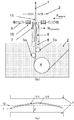
- the figure 1 shows a vertical sectional view of the hydrodynamic stabilization device of a metal strip according to the present invention.
- the figure 2 shows a top view of the strip between the spin knives, schematically showing the distance Z between the knives and the ideal reference plane of the strip, the bending defect ⁇ z) c and the displacement ⁇ z) v corresponding to the vibrations.
- the figure 3 represents respectively a sectional view of the spin wave showing schematically the phenomenon of splashing, on the one hand and of the spin wave in the presence of the end of the hydrodynamic pad, on the other hand.
- the figure 4 shows an elevational view of three preferred embodiments of the present invention, relating to the channels present on the back of each pad on the one hand and relating to the interface between contiguous pads on the other hand.
- the figure 5 shows a plan view of two preferred embodiments of the present invention, showing the relative arrangement of the pads on either side of the strip, according to its lack of camber relative to a reference plane.
- the figure 1 shows schematically a preferred embodiment of the hydrodynamic stabilization device of the invention arranged in front of the steel strip 1 driven in a continuous upward movement (that is to say in vertical strand), after passage by the bottom roller 4, by the descaling roller 5a and possibly by the stabilizing roller 5b of the bath of liquid zinc 2 and before its passage to the right of the spinning knives 3.
- the device of the invention is essentially in the form of at least one, but generally several, hydrodynamic pads 6 self-aligned (or self-aligning), pivotally mounted around a joint 7.
- the term "pads” means devices rigid planes such as plates. They can either be placed outside the bath 2, or have a partially submerged part 8, or even be completely submerged.
- the loading of the pads 6 aims to balance the hydrodynamic lift generated within the film of liquid metal at the strip-pad interface but also to flatten the strip 1 at its exit from the bath 2.
- fully emerged or completely submerged pads 6 advantageously make it possible to avoid trapping the foam found on the surface of the bath mainly at the start of the line, while fully emerged pads promote stabilization as close as possible to the wipers. .
- partially or completely submerged pads 6 make it possible to promote the preheating and the temperature maintenance of the pad by heat conduction via direct contact with the bath. This also makes it possible to take advantage of the speed profile in the vicinity of the strip, just before it leaves the bath and thus significantly improve the hydrodynamic lift (Rhydrodyn.), The thicknesses at the interface and therefore the operating safety vis- against a risk of contact between the pads and the strip.
- the camber defects ⁇ z) c and the displacements ⁇ z) v due to the vibrations will correspond to variations in coating thickness.
- the strip is closer to a spinning knife than the reference plane 12 which is by definition equidistant Z from the spinning knives, the final coating thickness will be smaller, and vice versa.
- the camber leads to a continuous variation in thickness over the strip width.
- the vibrations in rigid or "string” mode lead to an alternation of variations in thickness in the direction of travel, while the vibrations of higher order (“twisting" or “flapping") lead to variations affecting the longitudinal direction as much than the transverse direction.
- the device presented here therefore aims to overcome these different variations in order to obtain a flat and stable strip at right angles to the spinning knives and consequently to guarantee a uniform coating thickness in the two directions of the plane of the strip. .
- each pad 6 takes place on at least one side of the strip 1, and extend transversely essentially over the entire width of the strip 1. Also for the reason explained above, the back of each pad 6 advantageously has at least a channel or grooves 17 allowing the channeling of the return flow outside the supports of the joints.
- the pads 6 are optionally separated by a certain distance in the transverse direction and are essentially parallel to each other. Otherwise, they can possibly be in contact via a ceramic felt 18 or can be nested thanks to an added baffle 19 at their adjacent sides opposing the flow. ascending, which limits the risk of having an excess coating there, after spinning.
- the pads 6 are staggered on either side of the strip 1 shown with its lack of camber relative to the reference plane 12.
- an industrial programmable controller (PLC) can be added to the device for better control of the result, advantageously allowing a measurement of the camber, an analysis of the fault and a closed-loop correction of the forces (Fi).
- the pads 6 face each other on the strip 1.
- a PLC closed-loop measurement, analysis and correction system can be advantageously considered.
- the invention makes it possible, at least under certain operational conditions, to do without the stripper roller 5a and the stabilizing roller 5b, which is all the more advantageous since these generate additional vibrations following the wear of their bearings. submerged, that they also generate mattes and that their maintenance as well as their replacement require line shutdowns impacting plant productivity.
- the spring-shock absorber assembly 10 could simply be replaced by the “compressed air-internal friction” assembly of the jack.
- ⁇ b> ⁇ u> List of reference symbols ⁇ /u> ⁇ /b> 1
- Steel strip 9 Pneumatic jack 2
- Liquid zinc bath 10 Spring / shock absorber 3
- Spinning knives 11 Spin wave 4
- Bottom roll 12 Reference plane 5a
- Stripper roller 13 Upward flow 5b Stabilizing roller 14
- Hydrodynamic pads 15 Droplets (splashing) 7 Skate joint 16 Tapered shoe end 8 Submerged skate part 17 Channel (groove) 18 Ceramic felt 21 Industrial programmable controller (PLC) 19 Nested skates (chicane) 20
- PLC Industrial programmable controller
Landscapes
- Chemical & Material Sciences (AREA)
- Engineering & Computer Science (AREA)
- Chemical Kinetics & Catalysis (AREA)
- Materials Engineering (AREA)
- Mechanical Engineering (AREA)
- Metallurgy (AREA)
- Organic Chemistry (AREA)
- Computer Hardware Design (AREA)
- Coating With Molten Metal (AREA)
- Coating Apparatus (AREA)
- Application Of Or Painting With Fluid Materials (AREA)
- Drying Of Solid Materials (AREA)
Description
- La présente invention se rapporte à un dispositif hydrodynamique dissipatif permettant de stabiliser une bande métallique en défilement continu passant dans des essoreurs à l'issue d'une opération de revêtement au trempé.
- L'invention concerne plus particulièrement le domaine de la galvanisation au trempé à chaud d'une bande d'acier en mouvement continu. La stabilisation hydrodynamique de la bande est effectuée à la sortie du bain de métal liquide, dans le voisinage du dispositif d'essorage.
- On connaît la technique dite de "revêtement au trempé", qui constitue une méthode à la fois simple et efficace pour déposer un revêtement à la surface d'un objet. Selon cette technique, après une éventuelle préparation de la surface, on immerge l'objet à revêtir dans un bain comprenant le produit que l'on veut déposer sur ledit objet. L'objet est ensuite extrait du bain avec enlèvement de l'excès de liquide et le revêtement est rendu solide, par exemple par séchage, solidification, polymérisation, etc.
- L'une des applications les plus répandues de cette technique est le revêtement de pièces en acier telles que bandes ou fils au moyen d'un métal tel que le zinc qui lui servira ensuite de protection contre la corrosion.
- Après passage dans le bain de métal liquide, la pièce revêtue subit l'opération d'essorage. Cette opération est l'une des plus importantes dans le procédé de revêtement au trempé car elle permet la maîtrise de l'épaisseur finale de revêtement. D'une part, l'essorage doit être homogène sur toute la surface du produit, c'est-à-dire la largeur pour une bande et la circonférence pour un fil, et sur toute la longueur du produit à revêtir. En même temps, cette opération doit limiter strictement le dépôt à la valeur visée, que l'on exprime d'habitude soit en termes d'épaisseur déposée - typiquement de 3 à 50 µm -, soit en poids de la couche déposée par unité de surface - typiquement en gr/m2.
- Actuellement, l'essorage est généralement réalisé au moyen de lames ou jets de gaz, linéaires dans le cas des bandes et circulaires dans le cas de fils, issus de fentes et dirigés le plus souvent perpendiculairement à la surface à traiter. Les lames de gaz agissent comme des "racleurs pneumatiques" et présentent l'avantage de fonctionner sans contact mécanique et donc sans risque de griffer l'objet traité. De telles lames sont appelées "essoreurs à gaz" ou encore "couteaux d'essorage". Le gaz sous pression mis en oeuvre est soit de l'air, soit un gaz neutre tel que l'azote dans les applications les plus délicates comme le traitement des bandes d'acier destinées à la fabrication de pièces visibles pour la carrosserie d'automobiles.
- L'épaisseur finale du revêtement dépend notamment de la vitesse de défilement de la bande, de la distance entre la bande et les couteaux d'essorage et, enfin, de l'action exercée par le jet de gaz comprimé sur la bande.
- Or, il est connu que lors du passage de la bande sur le rouleau de fond, celle-ci prend la forme d'une tuile. Cette déformation plastique doit être corrigée à l'aide d'un second rouleau, dit décambreur, qui imprime à la bande une déformation plastique inverse. Accessoirement, un troisième rouleau, dit stabilisateur, permet de fixer la ligne de passe indépendamment du décambrage. Cependant, un mauvais contrôle de l'imbrication des rouleaux amène une déformation résiduelle et donc une planéité dégradée.
- D'autres phénomènes peuvent également altérer la planéité de la bande. Il peut s'agir d'une hétérogénéité de qualité de l'acier de base, de conditions de laminage dégradées ou encore de conditions de chauffage, de maintien en température et de refroidissement inhomogènes lors du cycle de recuit de la bande, avant son entrée dans le bain de métal liquide.
- En outre, certaines caractéristiques de l'installation tels que la présence de dispositifs de refroidissement avant le rouleau supérieur, l'excentricité de certains rouleaux, l'usure des roulements ou celle des paliers des rouleaux immergés, etc., induisent des vibrations de la bande passant dans les essoreurs.
- Au final, ces défauts de planéité et ces vibrations provoquent des variations d'épaisseur du revêtement qui affectent la qualité du produit et imposent une surconsommation de zinc pour garantir une épaisseur minimale de revêtement au client.
- D'autre part, pour une épaisseur de revêtement donnée, il est nécessaire d'augmenter la pression d'essorage lorsque la vitesse de bande augmente. Or il est connu que le déplacement de la bande ne peut dépasser une vitesse critique au-delà de laquelle le phénomène d'éclaboussures (ou « splashing », en anglais) apparaît : des gouttelettes sont arrachées à la vague d'essorage et projetées à la surface du bain et sur l'équipement. Il s'ensuit une dégradation importante de la qualité du produit ainsi qu'une augmentation considérable du volume d'écume à la surface du bain.
- Pour pallier ces problèmes, des constructeurs ont proposé de recourir à des dispositifs pneumatiques ou électromagnétiques de décambrage et de stabilisation de la bande ou d'autres dispositifs encore permettant d'éviter le splashing. On a également proposé de monter des rouleaux immergés sur paliers ou roulements en matériau céramique.
- Le document
JP 56 153136 A - Le document
JP 56 084452 A - Le document
JP 2005298908 A - L'objectif étant de stabiliser la bande dans les essoreurs, il est nécessaire que ce type de stabilisateur se situe dans leur voisinage, impliquant de souffler un gaz sous pression sur un revêtement d'épaisseur définitive mais non encore solidifié, ce qui risque d'affecter l'aspect du produit final. De plus, ces dispositifs ne garantissent pas la planéité de la bande au droit des essoreurs.
- Encore d'autres dispositifs de stabilisation hydrodynamique ont été proposés, comme dans le document
WO 03/054244 A1 EP 1 586 672 A1 décrit quant à lui un dispositif d'essorage mécanique n'ayant pas recours à une pompe, comprenant des lames d'essorage statiques utilisées conjointement avec un dispositif de stabilisation pneumatique placé en amont (application de pression) ou en aval (réduction de pression) de ces lames, de manière à générer un écoulement bi-phasique gaz/liquide entre ces lames et la bande. - Par ailleurs, on connaît également un certain nombre de méthodes de contrôle ou suppression des vibrations affectant une bande métallique en défilement continu basées sur la mise en oeuvre de moyens électromagnétiques (voir par exemple les documents
JP 10 298728 A JP 5 001362 A JP 9 143652 A JP 10 87755 A JP 8 010847 A - Les méthodes électromagnétiques sont basées sur le principe suivant. Des conducteurs dans lesquels circule un courant de fréquence élevée sont installés des deux côtés de la bande d'acier. Ils induisent dans la bande des courants en opposition de phase, les courants de Foucault. L'interaction entre les courants inducteurs et les courants de Foucault induits génère une pression magnétique tendant à stabiliser la bande d'acier. Une autre solution consiste à utiliser des électroaimants. Cependant, les méthodes de ce type impliquent un contrôle supplémentaire à cause de la force d'attraction magnétique, qui tend à rendre la bande instable. Par ailleurs, il est connu que les courants de haute fréquence mis en oeuvre provoquent une élévation de température dans la bande, ce qui est contraire à ce que l'on recherche dans cette étape du procédé.
- L'enseignement de ces diverses techniques ne permet pas de s'affranchir totalement des vibrations ou du manque de planéité de la bande, qui, même amoindris, subsistent généralement au droit des couteaux d'essorage. C'est donc à cet endroit qu'il convient d'agir mais sans altérer la formation du revêtement.
- La présente invention a pour but de proposer une solution au problème de stabilisation d'une bande métallique en défilement continu qui permette de s'affranchir des inconvénients de l'état de la technique.
- En particulier, la présente invention vise à stabiliser et/ou amortir les vibrations de la bande à la sortie d'un bain de métal liquide grâce à des moyens hydrodynamiques qui permettent de dissiper l'énergie de vibration générée dans la bande par l'installation.
- De plus, l'invention a encore pour but d'éviter, comme suggéré dans l'art antérieur, la mise en oeuvre de jets de gaz supplémentaires à proximité immédiate des essoreurs qui seraient susceptibles d'affecter l'aspect du produit final.
- L'invention a également pour but de décambrer la bande, et de manière plus générale d'améliorer la planéité de la bande à proximité même de l'endroit où l'épaisseur finale du revêtement est réalisée, c'est-à-dire au droit des essoreurs, ainsi que de garantir une épaisseur de revêtement uniforme dans la plan de la bande.
- Enfin, l'invention poursuit également le but d'apporter une solution au problème de splashing rencontré à haute vitesse de défilement.
- La présente invention se rapporte à une installation de revêtement au trempé d'une bande métallique en défilement continu, comprenant un bain de métal liquide de revêtement duquel la bande ressort en brin vertical, un rouleau de fond, un rouleau décambreur et le cas échéant un rouleau stabilisateur, tous immergés dans le bain de métal liquide, des couteaux d'essorage placés en sortie de bain et injectant un gaz sous pression pour enlever le surplus de revêtement non encore solidifié, créant une vague d'essorage présentant un flux de retour de métal liquide dirigé vers le bas, ainsi qu'un dispositif dissipatif de stabilisation hydrodynamique placé entre les couteaux d'essorage et le dernier rouleau immergé, comprenant une pluralité de patins hydrodynamiques destinés à une mise en charge sur au moins un côté de la bande métallique et montés pivotants autour d'articulations pour un autoalignement de ceux-ci, s'étendant en outre transversalement sur la largeur de la bande, et positionnés de sorte qu'en utilisation, le flux de retour de métal liquide de la vague d'essorage s'écoule au moins partiellement sur le dos des patins, c'est-à-dire sur la face de ceux-ci n'étant pas en vis-à-vis de la bande métallique en défilement continu.
- Selon des modes d'exécution préférés de l'invention, l'installation comporte en outre au moins une des caractéristiques suivantes, ou encore une combinaison appropriée de plusieurs de celles-ci :
- le dos de chaque patin est de nature non mouillante pour le métal liquide ou est pourvu d'un revêtement non mouillant ;
- au dos de chaque patin, se trouvent en outre, un chenal ou des rainures canalisant l'écoulement du flux de retour ;
- l'extrémité distale des patins par rapport au bain de métal liquide se trouve dans la zone d'essorage, est effilée et peut assurer un pré-essorage du revêtement en limitant le risque de splashing ;
- les articulations sont disposées de manière à ce que les extrémités distales effilées des patins soient quasi-stationnaires ;
- les patins sont soit complètement émergés, soit partiellement ou totalement immergés dans le métal liquide ;
- l'installation comprend des moyens extérieurs pour préchauffer les patins ;
- les patins situés du même côté de la bande sont essentiellement parallèles entre eux et séparés par un intervalle dans la direction transversale au défilement de la bande ;
- les patins situés du même côté de la bande sont en contact latéral via un feutre céramique placé dans cet intervalle ;
- les patins situés du même côté de la bande sont en contact latéral imbriqué via un chicanage ;
- l'installation comprend un vérin pneumatique pour la mise en charge indépendante de chaque patin ;
- le vérin pneumatique est assisté par un ensemble ressort-amortisseur ;
- les patins sont disposés de chaque côté de la bande en se faisant essentiellement face deux à deux ;
- les patins sont disposés de chaque côté de la bande et en quinconce ;
- les patins sont contrôlés en groupe ou individuellement par un automate programmable industriel qui assure au moins une mesure de la cambrure de la bande, une analyse du défaut et une correction en boucle fermée des forces appliquées sur les patins.
- L'installation de l'invention trouvera une application préférée dans le cadre d'un procédé industriel de revêtement au trempé à chaud en continu d'une bande métallique ayant une vitesse de défilement comprise préférentiellement entre 0.5 et >3 m/s (30 et >180 m/min), de préférence encore jusqu'à 10 m/s (600 m/min). Dans le cadre de ce procédé, la bande métallique sera constituée de préférence d'acier, d'aluminium, de zinc, de cuivre ou de l'un de leurs alliages. L'épaisseur de la bande métallique sera comprise préférentiellement entre 0,15 et 5 mm. Le métal fondu de revêtement comprendra de préférence du zinc, de l'aluminium, de l'étain, du magnésium, du silicium ou un alliage d'au moins deux de ces éléments. L'épaisseur de la couche métallique de revêtement obtenue après essorage sera de préférence comprise entre 3 et 50 µm. Le gaz sous pression injecté par les essoreurs à gaz sera de préférence de l'air, de l'azote ou du dioxyde de carbone.
- La
figure 1 représente une vue en coupe verticale du dispositif de stabilisation hydrodynamique d'une bande métallique selon la présente invention. - La
figure 2 représente une vue de dessus de la bande entre les couteaux d'essorage, montrant schématiquement la distance Z entre les couteaux et le plan idéal de référence de la bande, le défaut de cambrage Δz)c et le déplacement Δz)v correspondant aux vibrations. - La
figure 3 représente respectivement une vue en coupe de la vague d'essorage montrant schématiquement le phénomène de splashing, d'une part et de la vague d'essorage en présence de l'extrémité du patin hydrodynamique, d'autre part. - La
figure 4 représente une vue en élévation de trois modalités préférées d'exécution de la présente invention, relative aux chenaux présents au dos de chaque patin d'une part et relatives à l'interface entre patins jointifs d'autre part. - La
figure 5 représente une vue en plan de deux modalités préférées d'exécution de la présente invention, montrant la disposition relative des patins de part et d'autre de la bande, selon son défaut de cambrure par rapport à un plan de référence. - Pour fixer les idées, la
figure 1 représente schématiquement une forme d'exécution préférée du dispositif de stabilisation hydrodynamique de l'invention disposé en face de la bande d'acier 1 animée d'un mouvement continu vers le haut (c'est-à-dire en brin vertical), après passage par le rouleau de fond 4, par le rouleau décambreur 5a et éventuellement par le rouleau stabilisateur 5b du bain de zinc liquide 2 et avant son passage au droit des couteaux d'essorage 3. - Le dispositif de l'invention se présente essentiellement sous la forme d'au moins un, mais généralement plusieurs, patins hydrodynamiques 6 auto-alignés (ou auto-alignants), montés pivotants autour d'une articulation 7. On entend par patins des dispositifs plans rigides tels que des plaques. Ils peuvent soit être disposés en dehors du bain 2, soit avoir une partie partiellement immergée 8, soit encore être totalement immergés. La mise en charge des patins 6 vise à équilibrer la portance hydrodynamique générée au sein du film de métal liquide à l'interface bande-patin mais aussi à aplanir la bande 1 à sa sortie du bain 2.
- Plus précisément, des patins 6 complètement émergés ou complètement immergés permettent avantageusement d'éviter de piéger de l'écume se trouvant à la surface du bain principalement au démarrage de la ligne, tandis que des patins complètement émergés favorisent une stabilisation au plus près des essoreurs. Mais aussi, des patins 6 partiellement ou complètement immergés permettent de favoriser la préchauffe et le maintien en température du patin par conduction de chaleur via un contact direct avec le bain. Cela permet également de profiter du profil de vitesse au voisinage de la bande, juste avant qu'elle ne quitte le bain et ainsi améliorer significativement la portance hydrodynamique (Rhydrodyn.), les épaisseurs à l'interface et donc la sécurité de fonctionnement vis-à-vis d'un risque de contact entre les patins et la bande.
- Sur la
figure 2 , on voit qu'aux défauts de cambrure Δz)c et aux déplacements Δz)v dus aux vibrations vont correspondre des variations d'épaisseur de revêtement. Là où la bande est plus proche d'un couteau d'essorage que le plan de référence 12 qui se trouve par définition à égale distance Z des couteaux d'essorage, l'épaisseur finale de revêtement sera plus faible, et inversement. Plus particulièrement, la cambrure conduit à une variation continue d'épaisseur sur la largeur de bande. Les vibrations en mode rigide ou « string » conduisent à une alternance de variations d'épaisseur dans la direction de défilement, tandis que les vibrations d'ordre supérieur (« twisting » ou « flapping ») conduisent à des variations affectant autant la direction longitudinale que la direction transversale. Le dispositif présenté ici vise donc à s'affranchir de ces différentes variations en vue d'obtenir une bande plane et stable au droit des couteaux d'essorage et par suite de garantir une épaisseur de revêtement uniforme dans les deux directions du plan de la bande. - Sur la
figure 3 , on peut voir schématiquement le phénomène de splashing survenant au-delà d'une vitesse critique de défilement de la bande : pour une épaisseur finale donnée, lorsque la vitesse de bande augmente, le flux ascendant 13 et le flux de retour 14 viennent gonfler l'épaisseur de la vague d'essorage 11. Pour garder une épaisseur finale de revêtement constante, il est nécessaire d'augmenter la pression d'essorage et donc le gradient de pression et le cisaillement de la surface du film fluide dans la zone d'essorage 20. Au-delà d'une valeur critique du couple vitesse-épaisseur, le taux de cisaillement conduit à la projection de gouttelettes 15 de métal liquide (éclaboussures ou splashing). La présente invention se propose donc de limiter l'épaisseur de la vague d'essorage 11 en plaçant l'extrémité du patin 6, qui sera de préférence effilée, au sein de la zone d'essorage 20. L'efficacité en sera d'autant meilleure que le dos du patin 6, c'est-à-dire sa face opposée à la bande, est rendu non-mouillant, par nature ou par dépôt d'un revêtement adéquat. En effet, une partie du flux de retour va s'écouler au dos des patins 6 et il convient d'éviter que le métal liquide finisse par se figer à cet endroit. - Pour des bandes à revêtir allant généralement jusqu'à 2 mètres de large, il est nécessaire de disposer côte à côte plusieurs patins si l'on veut couvrir toute la largeur de la bande. Sur la
figure 4 , les patins 6 prennent place sur au moins un côté de la bande 1, et s'étendent transversalement essentiellement sur toute la largeur de la bande 1. Egalement pour la raison explicitée ci-dessus, le dos de chaque patin 6 présente avantageusement au moins un chenal ou des rainures 17 permettant la canalisation du flux de retour en dehors des appuis des articulations. Les patins 6 sont éventuellement séparés par une certaine distance dans la direction transversale et sont essentiellement parallèles entre eux. Dans le cas contraire, ils peuvent éventuellement être en contact via un feutre céramique 18 ou peuvent être imbriqués grâce à un chicanage rapporté 19 au niveau de leurs côtés adjacents s'opposant au flux ascendant, ce qui limite le risque d'avoir une surépaisseur de revêtement à cet endroit, après essorage. - Dans une première modalité représentée sur la
figure 5 (A) , les patins 6 sont placés en quinconce de part et d'autre de la bande 1 représentée avec son défaut de cambrure par rapport au plan de référence 12. Chaque patin 6 peut être soumis à une même force via son vérin d'appui ou à une force particulière (Fi) (i = 1, 2, 3, ..., N). Toujours selon l'invention, un automate programmable industriel (PLC) peut être ajouté au dispositif pour un meilleur contrôle du résultat en permettant avantageusement une mesure de la cambrure, une analyse du défaut et une correction en boucle fermée des forces (Fi). - Dans la seconde modalité d'exécution représentée sur la
figure 5 (B) , les patins 6 se font face de part et d'autre de la bande 1. Chaque paire de patins peut être soumise à une même force via son vérin d'appui ou à un différentiel de force (Fi)1 - (Fi)2 (i = 1, 2, ..., N). Ici aussi, le recours à un système de mesure, d'analyse et de correction en boucle fermée PLC peut être envisagé avantageusement. - L'invention permet, au moins dans certaines conditions opérationnelles, de se passer du rouleau décambreur 5a et du rouleau stabilisateur 5b, ce qui est d'autant plus avantageux que ceux-ci sont générateurs de vibrations supplémentaires suite à l'usure de leurs paliers immergés, qu'ils sont également générateurs de mattes et que leur entretien comme leur remplacement nécessitent des arrêts de ligne impactant la productivité de l'usine.
- D'autres modes de réalisation préférés de l'invention peuvent encore être envisagés, différant ici par la nature de l'amortissement réalisé. Par exemple, l'ensemble ressort-amortisseur 10 pourrait être simplement remplacé par l'ensemble « air comprimé-frottements internes » du vérin.
Liste des symboles de référence 1 Bande d'acier 9 Vérin pneumatique 2 Bain de zinc liquide 10 Ressort/amortisseur 3 Couteaux d'essorage 11 Vague d'essorage 4 Rouleau de fond 12 Plan de référence 5a Rouleau décambreur 13 Flux ascendant 5b Rouleau stabilisateur 14 Flux de retour 6 Patins hydrodynamiques 15 Gouttelettes (splashing) 7 Articulation de patin 16 Extrémité effilée de patin 8 Partie de patin immergée 17 Chenal (rainure) 18 Feutre céramique 21 Automate programmable industriel (PLC) 19 Patins imbriqués (chicane) 20 Zone d'essorage
Claims (15)
- Installation de revêtement au trempé d'une bande métallique (1) en défilement continu, comprenant un bain de métal liquide de revêtement (2) duquel la bande (1) ressort en brin vertical, un rouleau de fond (4), un rouleau décambreur (5a) et le cas échéant un rouleau stabilisateur (5b), immergés dans le bain de métal liquide (2), des couteaux d'essorage (3) placés en sortie de bain (2) et injectant un gaz sous pression pour enlever le surplus de revêtement non encore solidifié, créant une vague d'essorage (11) présentant un flux de retour (14) de métal liquide dirigé vers le bas, ainsi qu'un dispositif dissipatif de stabilisation hydrodynamique placé entre les couteaux d'essorage (3) et le dernier rouleau immergé (5a ou 5b), comprenant une pluralité de patins hydrodynamiques (6) destinés à une mise en charge sur au moins un côté de la bande métallique (1) et montés pivotants autour d'articulations (7) pour un autoalignement de ceux-ci, s'étendant en outre transversalement sur la largeur de la bande (1), et positionnés de sorte qu'en utilisation, le flux de retour de métal liquide (14) de la vague d'essorage (11) s'écoule au moins partiellement sur le dos des patins (6).
- Installation selon la revendication 1, caractérisée en ce que le dos de chaque patin (6) est de nature non mouillante pour le métal liquide ou est pourvu d'un revêtement non mouillant.
- Installation selon la revendication 1, caractérisée en ce qu'au dos de chaque patin (6), se trouvent en outre, un chenal ou des rainures (17) canalisant l'écoulement du flux de retour (14).
- Installation selon la revendication 1, caractérisée en ce que l'extrémité distale (16) des patins (6) par rapport au bain de métal liquide (2) se trouve dans la zone d'essorage (20), est effilée et peut assurer un pré-essorage du revêtement.
- Installation selon la revendication 4, caractérisée en ce que les articulations (7) sont disposées de manière à ce que les extrémités distales effilées (16) des patins (6) soient quasi-stationnaires.
- Installation selon la revendication 1, caractérisée en ce que les patins (6) ont une partie (8) partiellement immergée dans le bain de métal liquide (2).
- Installation selon la revendication 1, caractérisé en ce qu'elle comprend des moyens extérieurs pour préchauffer les patins (6).
- Installation selon la revendication 1, caractérisée en ce que les patins (6) situés du même côté de la bande sont essentiellement parallèles entre eux et séparés par un intervalle dans la direction transversale au défilement de la bande (1).
- Installation selon la revendication 8, caractérisée en ce que les patins (6) situés du même côté de la bande sont en contact latéral via un feutre céramique (18) placé dans cet intervalle.
- Installation selon la revendication 8, caractérisée en ce que les patins (6) situés du même côté de la bande sont en contact latéral imbriqué via un chicanage (19).
- Installation selon la revendication 1, caractérisée en ce qu'elle comprend un vérin pneumatique (9) pour la mise en charge indépendante de chaque patin (6).
- Installation selon la revendication 11, caractérisée en ce que le vérin pneumatique (9) est assisté par un ensemble ressort-amortisseur (10).
- Installation selon la revendication 1, caractérisée en ce que les patins (6) sont disposés de chaque côté de la bande (1) en se faisant essentiellement face deux à deux.
- Installation selon la revendication 1, caractérisée en ce que les patins (6) sont disposés de chaque côté de la bande (1) et en quinconce.
- Installation selon la revendication 13 ou 14, caractérisée en ce que les patins sont contrôlés en groupe ou individuellement par un automate programmable industriel (20) qui assure au moins une mesure de la cambrure de la bande (1), une analyse du défaut et une correction en boucle fermée des forces appliquées sur les patins (6).
Priority Applications (1)
| Application Number | Priority Date | Filing Date | Title |
|---|---|---|---|
| PL17700271T PL3408424T3 (pl) | 2016-01-29 | 2017-01-10 | Urządzenie do stabilizacji hydrodynamicznej taśmy metalowej przesuwającej się w sposób ciągły |
Applications Claiming Priority (2)
| Application Number | Priority Date | Filing Date | Title |
|---|---|---|---|
| BE2016/5073A BE1023837B1 (fr) | 2016-01-29 | 2016-01-29 | Dispositif pour la stabilisation hydrodynamique d'une bande metallique en defilement continu |
| PCT/EP2017/050379 WO2017129391A1 (fr) | 2016-01-29 | 2017-01-10 | Dispositif pour la stabilisation hydrodynamique d'une bande métallique en défilement continu |
Publications (2)
| Publication Number | Publication Date |
|---|---|
| EP3408424A1 EP3408424A1 (fr) | 2018-12-05 |
| EP3408424B1 true EP3408424B1 (fr) | 2020-03-18 |
Family
ID=57794282
Family Applications (1)
| Application Number | Title | Priority Date | Filing Date |
|---|---|---|---|
| EP17700271.4A Active EP3408424B1 (fr) | 2016-01-29 | 2017-01-10 | Dispositif pour la stabilisation hydrodynamique d'une bande métallique en défilement continu |
Country Status (14)
| Country | Link |
|---|---|
| US (1) | US10550459B2 (fr) |
| EP (1) | EP3408424B1 (fr) |
| JP (1) | JP6869248B2 (fr) |
| KR (1) | KR20180103992A (fr) |
| CN (1) | CN109072395B (fr) |
| BE (1) | BE1023837B1 (fr) |
| BR (1) | BR112018015424B1 (fr) |
| CA (1) | CA3011266C (fr) |
| ES (1) | ES2790198T3 (fr) |
| PL (1) | PL3408424T3 (fr) |
| RU (1) | RU2715933C2 (fr) |
| UA (1) | UA122708C2 (fr) |
| WO (1) | WO2017129391A1 (fr) |
| ZA (1) | ZA201804419B (fr) |
Families Citing this family (4)
| Publication number | Priority date | Publication date | Assignee | Title |
|---|---|---|---|---|
| EP4549610A1 (fr) * | 2023-11-03 | 2025-05-07 | Tata Steel IJmuiden B.V. | Appareil de revêtement par immersion à chaud, dispositif et procédé d'essuyage d'une bande métallique revêtue |
| WO2025132891A1 (fr) * | 2023-12-21 | 2025-06-26 | Tata Steel Ijmuiden B.V. | Dispositif de revêtement par immersion à chaud et procédé de revêtement d'une bande métallique dans un dispositif de revêtement par immersion à chaud |
| EP4624621A1 (fr) | 2024-03-25 | 2025-10-01 | Tata Steel IJmuiden B.V. | Dispositif de revêtement par immersion à chaud avec des moyens de stabilisation du substrat et procédé de revêtement utilisant un dispositif de revêtement par immersion à chaud |
| CN120738582B (zh) * | 2025-08-28 | 2026-01-06 | 宝鸡新钛程金属复合材料有限公司 | 一种钛钼镍复合板的镀锌加工设备 |
Family Cites Families (37)
| Publication number | Priority date | Publication date | Assignee | Title |
|---|---|---|---|---|
| US2093857A (en) * | 1934-10-04 | 1937-09-21 | Keystone Steel & Wire Co | Method and apparatus for hot galvanizing iron or steel articles |
| US2398034A (en) * | 1943-05-11 | 1946-04-09 | American Rolling Mill Co | Treatment means and method for hot coated strip |
| US2435766A (en) * | 1944-04-11 | 1948-02-10 | Western Electric Co | Wiper for use in metal plating apparatus |
| US2413216A (en) * | 1944-04-14 | 1946-12-24 | Surface Combustion Corp | Continuous strip wiping apparatus |
| US2914419A (en) * | 1953-08-03 | 1959-11-24 | Armco Steel Corp | Method and apparatus for continuously coating a metal strand-like article with molten metal |
| US2817312A (en) * | 1955-04-11 | 1957-12-24 | Thor H Westby | Hot dip coating apparatus |
| GB1131951A (en) * | 1965-06-08 | 1968-10-30 | Hitachi Ltd | Method of and apparatus for continuous hot dip metal coating |
| GB1373998A (en) * | 1971-01-27 | 1974-11-13 | Inventing Ab | Method and a device for applying a coating composition to a web |
| JPS5229832A (en) * | 1975-09-02 | 1977-03-07 | Nippon Steel Corp | Method and apparatus for the coating and wiping of liquid substance |
| JPS5256025A (en) * | 1975-11-04 | 1977-05-09 | Hitachi Ltd | Strippsupporting device in molten plating apparatus |
| JPS5591967A (en) * | 1978-12-30 | 1980-07-11 | Nippon Steel Corp | One-side hot dipping method for steel strip |
| JPS55100971A (en) * | 1979-01-25 | 1980-08-01 | Nisshin Steel Co Ltd | Hot galvanizer for steel strip |
| JPS5911662B2 (ja) | 1979-12-14 | 1984-03-16 | 新日本製鐵株式会社 | ストリツプの振動防止方法 |
| NZ192668A (en) * | 1980-01-22 | 1984-12-14 | N Z Wire Ind Ltd | Apparatus for wiping wire or strip emerging vertically from molten metal bath |
| JPS56153136A (en) | 1980-04-30 | 1981-11-27 | Nippon Steel Corp | Noncontact type vibration damping method for strip |
| ES534131A0 (es) * | 1984-02-23 | 1985-11-01 | Australian Wire Ind Pty | Metodo y aparato para limpiar por frotamiento un alambre o fleje |
| JP2570924B2 (ja) | 1991-06-25 | 1997-01-16 | 日本鋼管株式会社 | 連続通板する鋼板の振動および板反り防止方法 |
| JP3233781B2 (ja) | 1994-06-28 | 2001-11-26 | 三菱重工業株式会社 | ストリップの形状矯正装置 |
| JP3222739B2 (ja) | 1995-11-16 | 2001-10-29 | 川崎製鉄株式会社 | 溶融金属めっきラインにおける金属ストリップの振動防止方法およびその装置 |
| JP3625961B2 (ja) | 1996-09-19 | 2005-03-02 | 三菱化学株式会社 | グラフト共重合樹脂の製造方法 |
| CA2225537C (fr) * | 1996-12-27 | 2001-05-15 | Mitsubishi Heavy Industries, Ltd. | Dispositif et methode de revetement metallique a chaud |
| JPH10298728A (ja) | 1997-04-23 | 1998-11-10 | Nkk Corp | 鋼板の振動・形状制御方法 |
| KR20000039450A (ko) * | 1998-12-14 | 2000-07-05 | 이구택 | 직류전자석을 이용한 강판 진동방지장치를구비한 용융아연 도금설비 |
| DE10160949A1 (de) | 2001-12-12 | 2003-06-26 | Sms Demag Ag | System und Verfahren zum Beschichten der Oberfläche eines Metallbandes |
| JP2005171336A (ja) * | 2003-12-12 | 2005-06-30 | Mitsubishi-Hitachi Metals Machinery Inc | 溶融金属めっき方法及び設備 |
| JP4451194B2 (ja) | 2004-04-13 | 2010-04-14 | 三菱日立製鉄機械株式会社 | 液体ワイピング装置 |
| JP5493260B2 (ja) * | 2007-10-09 | 2014-05-14 | Jfeスチール株式会社 | 溶融金属めっき鋼帯製造装置及び溶融金属めっき鋼帯の製造方法 |
| ITMI20081207A1 (it) * | 2008-06-30 | 2010-01-01 | Danieli Off Mecc | Dispositivo elettromagnetico per il rivestimento mediante immersione continua a caldo di prodotti metallici piani e relativo processo di rivestimento |
| CA2675004A1 (fr) * | 2008-08-08 | 2010-02-08 | David E. Green | Bois renforce pour surmonter le defaut de resistance interlaminaire au cisaillement et procede de fabrication |
| WO2010130884A1 (fr) * | 2009-05-14 | 2010-11-18 | Arcelormittal Investigacion Y Desarrollo Sl | Procédé de fabrication d'une bande métallique revêtue présentant un aspect amélioré |
| KR20120025850A (ko) * | 2010-09-08 | 2012-03-16 | 동부제철 주식회사 | 용융도금공정에서의 강판의 진동 제어 장치 및 방법 |
| EP2691553A1 (fr) * | 2011-03-30 | 2014-02-05 | Tata Steel Nederland Technology B.V. | Appareil permettant de recouvrir un matériau en bande mobile avec un matériau de revêtement métallique |
| ITMI20111544A1 (it) * | 2011-08-24 | 2013-02-25 | Danieli Off Mecc | Impianto per il rivestimento mediante immersione continua a caldo di prodotti metallici piani e relativo processo di rivestimento |
| KR101531461B1 (ko) * | 2012-05-10 | 2015-06-24 | 신닛테츠스미킨 카부시키카이샤 | 강판 형상 제어 방법 및 강판 형상 제어 장치 |
| DE102012106106A1 (de) * | 2012-07-06 | 2014-09-18 | Thyssenkrupp Steel Europe Ag | Verfahren und Vorrichtung zur Vermeidung von durch Zinkstaub verursachten Oberflächenfehlern in einer kontinuierlichen Bandverzinkung |
| JP6303581B2 (ja) * | 2014-02-19 | 2018-04-04 | 新日鐵住金株式会社 | ワイピング装置 |
| KR101847567B1 (ko) * | 2015-12-24 | 2018-04-10 | 주식회사 포스코 | 미세하고 균일한 도금 조직을 갖는 도금 강판 |
-
2016
- 2016-01-29 BE BE2016/5073A patent/BE1023837B1/fr not_active IP Right Cessation
-
2017
- 2017-01-10 JP JP2018537862A patent/JP6869248B2/ja not_active Expired - Fee Related
- 2017-01-10 UA UAA201808717A patent/UA122708C2/uk unknown
- 2017-01-10 KR KR1020187023426A patent/KR20180103992A/ko not_active Withdrawn
- 2017-01-10 BR BR112018015424-5A patent/BR112018015424B1/pt not_active IP Right Cessation
- 2017-01-10 ES ES17700271T patent/ES2790198T3/es active Active
- 2017-01-10 CA CA3011266A patent/CA3011266C/fr active Active
- 2017-01-10 EP EP17700271.4A patent/EP3408424B1/fr active Active
- 2017-01-10 WO PCT/EP2017/050379 patent/WO2017129391A1/fr not_active Ceased
- 2017-01-10 US US16/072,927 patent/US10550459B2/en active Active
- 2017-01-10 RU RU2018128792A patent/RU2715933C2/ru active
- 2017-01-10 CN CN201780008581.5A patent/CN109072395B/zh not_active Expired - Fee Related
- 2017-01-10 PL PL17700271T patent/PL3408424T3/pl unknown
-
2018
- 2018-07-02 ZA ZA2018/04419A patent/ZA201804419B/en unknown
Non-Patent Citations (1)
| Title |
|---|
| None * |
Also Published As
| Publication number | Publication date |
|---|---|
| BE1023837A1 (fr) | 2017-08-08 |
| BR112018015424B1 (pt) | 2022-04-12 |
| UA122708C2 (uk) | 2020-12-28 |
| KR20180103992A (ko) | 2018-09-19 |
| BE1023837B1 (fr) | 2017-08-09 |
| JP2019504926A (ja) | 2019-02-21 |
| RU2715933C2 (ru) | 2020-03-04 |
| RU2018128792A (ru) | 2020-03-03 |
| EP3408424A1 (fr) | 2018-12-05 |
| JP6869248B2 (ja) | 2021-05-12 |
| BR112018015424A2 (pt) | 2018-12-18 |
| PL3408424T3 (pl) | 2020-08-10 |
| CA3011266C (fr) | 2023-05-02 |
| ZA201804419B (en) | 2019-05-29 |
| RU2018128792A3 (fr) | 2020-03-03 |
| CN109072395B (zh) | 2021-02-26 |
| WO2017129391A1 (fr) | 2017-08-03 |
| US10550459B2 (en) | 2020-02-04 |
| US20190032188A1 (en) | 2019-01-31 |
| CN109072395A (zh) | 2018-12-21 |
| ES2790198T3 (es) | 2020-10-27 |
| CA3011266A1 (fr) | 2017-08-03 |
Similar Documents
| Publication | Publication Date | Title |
|---|---|---|
| CA3011266C (fr) | Dispositif pour la stabilisation hydrodynamique d'une bande metallique en defilement continu | |
| EP0023472B1 (fr) | Procédé de revêtement en continu d'un substrat métallique sur une partie au moins d'au moins l'une de ses faces et dispositif pour la mise en oeuvre de ce procédé | |
| EP0298852B1 (fr) | Procédé et installation de planage d'une bande métallique | |
| FR2532869A1 (fr) | Procede de revetement en continu d'une bande d'aluminium | |
| CN101796209A (zh) | 热镀金属钢带的制造装置 | |
| EP2279278B1 (fr) | Système et méthode adaptés au guidage d'un dispositif d'essorage d'un produit de galvanisation | |
| EP2132353A1 (fr) | Procede et installation de depot en continu d'un revetement sur un support en bande | |
| EP2276867B1 (fr) | Dispositif et une méthode de positionnement de deux déflecteurs associés à un essorage d'un produit de galvanisation | |
| KR100838737B1 (ko) | 용융아연도금장치의 싱크롤과 스테빌라이징롤용 저어널베어링 보호장치 | |
| EP0131483B1 (fr) | Procédé et dispositif pour la fabrication de feuilles de matière plastique de bonne qualité optique, par coulée | |
| BE1018202A3 (fr) | Dispositif pour l'essorage hydrodynamique d'une bande metallique en defilement contunu. | |
| BE1032289B1 (fr) | Procédé de galvanisation de fils en défilement continu et système de filière d'essuyage | |
| EP1728888B1 (fr) | Dispositif pour la stabilisation pneumatique d'une bande métallique en défilement continu | |
| FR2745513A1 (fr) | Procede et dispositif de nettoyage de fil de cuivre de forme plate | |
| EP0140026A2 (fr) | Dispositif de refroidissement de produits métalliques laminés | |
| FR2807070A1 (fr) | Procede et dispositif pour realiser un revetement metallique sur un objet sortant d'un bain de metal fondu | |
| EP1412095B1 (fr) | Procede et dispositif de revetement en continu d'une bande par un film fluide d'epaisseur predeterminee en polymere reticulable exempt de solvant ou de diluant | |
| WO1996038599A1 (fr) | Procede et dispositif pour revetir une bande metallique d'un metal ou d'un alliage a plus bas point de fusion ou de liquide que celui du materiau constituant la bande | |
| FR2485569A1 (fr) | Appareil de metallisation par immersion a chaud d'une face d'une bande | |
| BE543242A (fr) | ||
| BE699500A (fr) | ||
| BE895935A (fr) | Perfectionnements aux procedes de revetement de produits metalliques | |
| FR2563238A1 (fr) | Dispositif de realisation d'un revetement tres mince sur une face d'une bande galvanisee | |
| BE521224A (fr) |
Legal Events
| Date | Code | Title | Description |
|---|---|---|---|
| STAA | Information on the status of an ep patent application or granted ep patent |
Free format text: STATUS: UNKNOWN |
|
| STAA | Information on the status of an ep patent application or granted ep patent |
Free format text: STATUS: THE INTERNATIONAL PUBLICATION HAS BEEN MADE |
|
| PUAI | Public reference made under article 153(3) epc to a published international application that has entered the european phase |
Free format text: ORIGINAL CODE: 0009012 |
|
| STAA | Information on the status of an ep patent application or granted ep patent |
Free format text: STATUS: REQUEST FOR EXAMINATION WAS MADE |
|
| 17P | Request for examination filed |
Effective date: 20180626 |
|
| AK | Designated contracting states |
Kind code of ref document: A1 Designated state(s): AL AT BE BG CH CY CZ DE DK EE ES FI FR GB GR HR HU IE IS IT LI LT LU LV MC MK MT NL NO PL PT RO RS SE SI SK SM TR |
|
| AX | Request for extension of the european patent |
Extension state: BA ME |
|
| DAV | Request for validation of the european patent (deleted) | ||
| DAX | Request for extension of the european patent (deleted) | ||
| GRAP | Despatch of communication of intention to grant a patent |
Free format text: ORIGINAL CODE: EPIDOSNIGR1 |
|
| STAA | Information on the status of an ep patent application or granted ep patent |
Free format text: STATUS: GRANT OF PATENT IS INTENDED |
|
| INTG | Intention to grant announced |
Effective date: 20190604 |
|
| GRAJ | Information related to disapproval of communication of intention to grant by the applicant or resumption of examination proceedings by the epo deleted |
Free format text: ORIGINAL CODE: EPIDOSDIGR1 |
|
| STAA | Information on the status of an ep patent application or granted ep patent |
Free format text: STATUS: REQUEST FOR EXAMINATION WAS MADE |
|
| INTC | Intention to grant announced (deleted) | ||
| GRAP | Despatch of communication of intention to grant a patent |
Free format text: ORIGINAL CODE: EPIDOSNIGR1 |
|
| STAA | Information on the status of an ep patent application or granted ep patent |
Free format text: STATUS: GRANT OF PATENT IS INTENDED |
|
| INTG | Intention to grant announced |
Effective date: 20191010 |
|
| GRAS | Grant fee paid |
Free format text: ORIGINAL CODE: EPIDOSNIGR3 |
|
| GRAA | (expected) grant |
Free format text: ORIGINAL CODE: 0009210 |
|
| STAA | Information on the status of an ep patent application or granted ep patent |
Free format text: STATUS: THE PATENT HAS BEEN GRANTED |
|
| AK | Designated contracting states |
Kind code of ref document: B1 Designated state(s): AL AT BE BG CH CY CZ DE DK EE ES FI FR GB GR HR HU IE IS IT LI LT LU LV MC MK MT NL NO PL PT RO RS SE SI SK SM TR |
|
| REG | Reference to a national code |
Ref country code: GB Ref legal event code: FG4D Free format text: NOT ENGLISH |
|
| REG | Reference to a national code |
Ref country code: AT Ref legal event code: REF Ref document number: 1245989 Country of ref document: AT Kind code of ref document: T Effective date: 20200415 Ref country code: IE Ref legal event code: FG4D Free format text: LANGUAGE OF EP DOCUMENT: FRENCH |
|
| REG | Reference to a national code |
Ref country code: DE Ref legal event code: R096 Ref document number: 602017013240 Country of ref document: DE |
|
| REG | Reference to a national code |
Ref country code: NL Ref legal event code: FP |
|
| PG25 | Lapsed in a contracting state [announced via postgrant information from national office to epo] |
Ref country code: NO Free format text: LAPSE BECAUSE OF FAILURE TO SUBMIT A TRANSLATION OF THE DESCRIPTION OR TO PAY THE FEE WITHIN THE PRESCRIBED TIME-LIMIT Effective date: 20200618 Ref country code: RS Free format text: LAPSE BECAUSE OF FAILURE TO SUBMIT A TRANSLATION OF THE DESCRIPTION OR TO PAY THE FEE WITHIN THE PRESCRIBED TIME-LIMIT Effective date: 20200318 Ref country code: FI Free format text: LAPSE BECAUSE OF FAILURE TO SUBMIT A TRANSLATION OF THE DESCRIPTION OR TO PAY THE FEE WITHIN THE PRESCRIBED TIME-LIMIT Effective date: 20200318 |
|
| PG25 | Lapsed in a contracting state [announced via postgrant information from national office to epo] |
Ref country code: SE Free format text: LAPSE BECAUSE OF FAILURE TO SUBMIT A TRANSLATION OF THE DESCRIPTION OR TO PAY THE FEE WITHIN THE PRESCRIBED TIME-LIMIT Effective date: 20200318 Ref country code: LV Free format text: LAPSE BECAUSE OF FAILURE TO SUBMIT A TRANSLATION OF THE DESCRIPTION OR TO PAY THE FEE WITHIN THE PRESCRIBED TIME-LIMIT Effective date: 20200318 Ref country code: HR Free format text: LAPSE BECAUSE OF FAILURE TO SUBMIT A TRANSLATION OF THE DESCRIPTION OR TO PAY THE FEE WITHIN THE PRESCRIBED TIME-LIMIT Effective date: 20200318 Ref country code: BG Free format text: LAPSE BECAUSE OF FAILURE TO SUBMIT A TRANSLATION OF THE DESCRIPTION OR TO PAY THE FEE WITHIN THE PRESCRIBED TIME-LIMIT Effective date: 20200618 Ref country code: GR Free format text: LAPSE BECAUSE OF FAILURE TO SUBMIT A TRANSLATION OF THE DESCRIPTION OR TO PAY THE FEE WITHIN THE PRESCRIBED TIME-LIMIT Effective date: 20200619 |
|
| REG | Reference to a national code |
Ref country code: LT Ref legal event code: MG4D |
|
| REG | Reference to a national code |
Ref country code: ES Ref legal event code: FG2A Ref document number: 2790198 Country of ref document: ES Kind code of ref document: T3 Effective date: 20201027 |
|
| PG25 | Lapsed in a contracting state [announced via postgrant information from national office to epo] |
Ref country code: IS Free format text: LAPSE BECAUSE OF FAILURE TO SUBMIT A TRANSLATION OF THE DESCRIPTION OR TO PAY THE FEE WITHIN THE PRESCRIBED TIME-LIMIT Effective date: 20200718 Ref country code: CZ Free format text: LAPSE BECAUSE OF FAILURE TO SUBMIT A TRANSLATION OF THE DESCRIPTION OR TO PAY THE FEE WITHIN THE PRESCRIBED TIME-LIMIT Effective date: 20200318 Ref country code: EE Free format text: LAPSE BECAUSE OF FAILURE TO SUBMIT A TRANSLATION OF THE DESCRIPTION OR TO PAY THE FEE WITHIN THE PRESCRIBED TIME-LIMIT Effective date: 20200318 Ref country code: SM Free format text: LAPSE BECAUSE OF FAILURE TO SUBMIT A TRANSLATION OF THE DESCRIPTION OR TO PAY THE FEE WITHIN THE PRESCRIBED TIME-LIMIT Effective date: 20200318 Ref country code: PT Free format text: LAPSE BECAUSE OF FAILURE TO SUBMIT A TRANSLATION OF THE DESCRIPTION OR TO PAY THE FEE WITHIN THE PRESCRIBED TIME-LIMIT Effective date: 20200812 Ref country code: RO Free format text: LAPSE BECAUSE OF FAILURE TO SUBMIT A TRANSLATION OF THE DESCRIPTION OR TO PAY THE FEE WITHIN THE PRESCRIBED TIME-LIMIT Effective date: 20200318 Ref country code: LT Free format text: LAPSE BECAUSE OF FAILURE TO SUBMIT A TRANSLATION OF THE DESCRIPTION OR TO PAY THE FEE WITHIN THE PRESCRIBED TIME-LIMIT Effective date: 20200318 Ref country code: SK Free format text: LAPSE BECAUSE OF FAILURE TO SUBMIT A TRANSLATION OF THE DESCRIPTION OR TO PAY THE FEE WITHIN THE PRESCRIBED TIME-LIMIT Effective date: 20200318 |
|
| REG | Reference to a national code |
Ref country code: AT Ref legal event code: UEP Ref document number: 1245989 Country of ref document: AT Kind code of ref document: T Effective date: 20200318 |
|
| REG | Reference to a national code |
Ref country code: DE Ref legal event code: R097 Ref document number: 602017013240 Country of ref document: DE |
|
| PLBE | No opposition filed within time limit |
Free format text: ORIGINAL CODE: 0009261 |
|
| STAA | Information on the status of an ep patent application or granted ep patent |
Free format text: STATUS: NO OPPOSITION FILED WITHIN TIME LIMIT |
|
| PG25 | Lapsed in a contracting state [announced via postgrant information from national office to epo] |
Ref country code: IT Free format text: LAPSE BECAUSE OF FAILURE TO SUBMIT A TRANSLATION OF THE DESCRIPTION OR TO PAY THE FEE WITHIN THE PRESCRIBED TIME-LIMIT Effective date: 20200318 Ref country code: DK Free format text: LAPSE BECAUSE OF FAILURE TO SUBMIT A TRANSLATION OF THE DESCRIPTION OR TO PAY THE FEE WITHIN THE PRESCRIBED TIME-LIMIT Effective date: 20200318 |
|
| 26N | No opposition filed |
Effective date: 20201221 |
|
| PG25 | Lapsed in a contracting state [announced via postgrant information from national office to epo] |
Ref country code: SI Free format text: LAPSE BECAUSE OF FAILURE TO SUBMIT A TRANSLATION OF THE DESCRIPTION OR TO PAY THE FEE WITHIN THE PRESCRIBED TIME-LIMIT Effective date: 20200318 |
|
| PG25 | Lapsed in a contracting state [announced via postgrant information from national office to epo] |
Ref country code: MC Free format text: LAPSE BECAUSE OF FAILURE TO SUBMIT A TRANSLATION OF THE DESCRIPTION OR TO PAY THE FEE WITHIN THE PRESCRIBED TIME-LIMIT Effective date: 20200318 |
|
| REG | Reference to a national code |
Ref country code: CH Ref legal event code: PL |
|
| GBPC | Gb: european patent ceased through non-payment of renewal fee |
Effective date: 20210110 |
|
| PG25 | Lapsed in a contracting state [announced via postgrant information from national office to epo] |
Ref country code: LU Free format text: LAPSE BECAUSE OF NON-PAYMENT OF DUE FEES Effective date: 20210110 |
|
| PG25 | Lapsed in a contracting state [announced via postgrant information from national office to epo] |
Ref country code: CH Free format text: LAPSE BECAUSE OF NON-PAYMENT OF DUE FEES Effective date: 20210131 Ref country code: LI Free format text: LAPSE BECAUSE OF NON-PAYMENT OF DUE FEES Effective date: 20210131 Ref country code: GB Free format text: LAPSE BECAUSE OF NON-PAYMENT OF DUE FEES Effective date: 20210110 |
|
| PG25 | Lapsed in a contracting state [announced via postgrant information from national office to epo] |
Ref country code: IE Free format text: LAPSE BECAUSE OF NON-PAYMENT OF DUE FEES Effective date: 20210110 |
|
| P01 | Opt-out of the competence of the unified patent court (upc) registered |
Effective date: 20230413 |
|
| PG25 | Lapsed in a contracting state [announced via postgrant information from national office to epo] |
Ref country code: CY Free format text: LAPSE BECAUSE OF FAILURE TO SUBMIT A TRANSLATION OF THE DESCRIPTION OR TO PAY THE FEE WITHIN THE PRESCRIBED TIME-LIMIT Effective date: 20200318 |
|
| PG25 | Lapsed in a contracting state [announced via postgrant information from national office to epo] |
Ref country code: HU Free format text: LAPSE BECAUSE OF FAILURE TO SUBMIT A TRANSLATION OF THE DESCRIPTION OR TO PAY THE FEE WITHIN THE PRESCRIBED TIME-LIMIT; INVALID AB INITIO Effective date: 20170110 |
|
| PGFP | Annual fee paid to national office [announced via postgrant information from national office to epo] |
Ref country code: NL Payment date: 20231219 Year of fee payment: 8 Ref country code: FR Payment date: 20231219 Year of fee payment: 8 |
|
| PGFP | Annual fee paid to national office [announced via postgrant information from national office to epo] |
Ref country code: PL Payment date: 20231221 Year of fee payment: 8 Ref country code: BE Payment date: 20231219 Year of fee payment: 8 |
|
| PGFP | Annual fee paid to national office [announced via postgrant information from national office to epo] |
Ref country code: ES Payment date: 20240202 Year of fee payment: 8 |
|
| PGFP | Annual fee paid to national office [announced via postgrant information from national office to epo] |
Ref country code: AT Payment date: 20231222 Year of fee payment: 8 |
|
| PG25 | Lapsed in a contracting state [announced via postgrant information from national office to epo] |
Ref country code: MK Free format text: LAPSE BECAUSE OF FAILURE TO SUBMIT A TRANSLATION OF THE DESCRIPTION OR TO PAY THE FEE WITHIN THE PRESCRIBED TIME-LIMIT Effective date: 20200318 |
|
| PGFP | Annual fee paid to national office [announced via postgrant information from national office to epo] |
Ref country code: DE Payment date: 20231219 Year of fee payment: 8 |
|
| PG25 | Lapsed in a contracting state [announced via postgrant information from national office to epo] |
Ref country code: MT Free format text: LAPSE BECAUSE OF FAILURE TO SUBMIT A TRANSLATION OF THE DESCRIPTION OR TO PAY THE FEE WITHIN THE PRESCRIBED TIME-LIMIT Effective date: 20200318 |
|
| REG | Reference to a national code |
Ref country code: DE Ref legal event code: R119 Ref document number: 602017013240 Country of ref document: DE |
|
| REG | Reference to a national code |
Ref country code: NL Ref legal event code: MM Effective date: 20250201 |
|
| REG | Reference to a national code |
Ref country code: AT Ref legal event code: MM01 Ref document number: 1245989 Country of ref document: AT Kind code of ref document: T Effective date: 20250110 |
|
| PG25 | Lapsed in a contracting state [announced via postgrant information from national office to epo] |
Ref country code: DE Free format text: LAPSE BECAUSE OF NON-PAYMENT OF DUE FEES Effective date: 20250801 |
|
| PG25 | Lapsed in a contracting state [announced via postgrant information from national office to epo] |
Ref country code: NL Free format text: LAPSE BECAUSE OF NON-PAYMENT OF DUE FEES Effective date: 20250201 |
|
| PG25 | Lapsed in a contracting state [announced via postgrant information from national office to epo] |
Ref country code: BE Free format text: LAPSE BECAUSE OF NON-PAYMENT OF DUE FEES Effective date: 20250131 |
|
| PG25 | Lapsed in a contracting state [announced via postgrant information from national office to epo] |
Ref country code: AT Free format text: LAPSE BECAUSE OF NON-PAYMENT OF DUE FEES Effective date: 20250110 Ref country code: FR Free format text: LAPSE BECAUSE OF NON-PAYMENT OF DUE FEES Effective date: 20250131 |
|
| REG | Reference to a national code |
Ref country code: BE Ref legal event code: MM Effective date: 20250131 |
|
| PG25 | Lapsed in a contracting state [announced via postgrant information from national office to epo] |
Ref country code: TR Free format text: LAPSE BECAUSE OF FAILURE TO SUBMIT A TRANSLATION OF THE DESCRIPTION OR TO PAY THE FEE WITHIN THE PRESCRIBED TIME-LIMIT Effective date: 20200318 |
|
| REG | Reference to a national code |
Ref country code: ES Ref legal event code: FD2A Effective date: 20260227 |
|
| PG25 | Lapsed in a contracting state [announced via postgrant information from national office to epo] |
Ref country code: ES Free format text: LAPSE BECAUSE OF NON-PAYMENT OF DUE FEES Effective date: 20250111 |