EP3403828B1 - Workpiece transfer and printing - Google Patents
Workpiece transfer and printing Download PDFInfo
- Publication number
- EP3403828B1 EP3403828B1 EP18000455.8A EP18000455A EP3403828B1 EP 3403828 B1 EP3403828 B1 EP 3403828B1 EP 18000455 A EP18000455 A EP 18000455A EP 3403828 B1 EP3403828 B1 EP 3403828B1
- Authority
- EP
- European Patent Office
- Prior art keywords
- platen
- printing
- workpiece
- rotary table
- production line
- Prior art date
- Legal status (The legal status is an assumption and is not a legal conclusion. Google has not performed a legal analysis and makes no representation as to the accuracy of the status listed.)
- Active
Links
Images


Classifications
-
- H—ELECTRICITY
- H05—ELECTRIC TECHNIQUES NOT OTHERWISE PROVIDED FOR
- H05K—PRINTED CIRCUITS; CASINGS OR CONSTRUCTIONAL DETAILS OF ELECTRIC APPARATUS; MANUFACTURE OF ASSEMBLAGES OF ELECTRICAL COMPONENTS
- H05K3/00—Apparatus or processes for manufacturing printed circuits
- H05K3/10—Apparatus or processes for manufacturing printed circuits in which conductive material is applied to the insulating support in such a manner as to form the desired conductive pattern
- H05K3/12—Apparatus or processes for manufacturing printed circuits in which conductive material is applied to the insulating support in such a manner as to form the desired conductive pattern using thick film techniques, e.g. printing techniques to apply the conductive material or similar techniques for applying conductive paste or ink patterns
- H05K3/1216—Apparatus or processes for manufacturing printed circuits in which conductive material is applied to the insulating support in such a manner as to form the desired conductive pattern using thick film techniques, e.g. printing techniques to apply the conductive material or similar techniques for applying conductive paste or ink patterns by screen printing or stencil printing
-
- H—ELECTRICITY
- H10—SEMICONDUCTOR DEVICES; ELECTRIC SOLID-STATE DEVICES NOT OTHERWISE PROVIDED FOR
- H10P—GENERIC PROCESSES OR APPARATUS FOR THE MANUFACTURE OR TREATMENT OF DEVICES COVERED BY CLASS H10
- H10P72/00—Handling or holding of wafers, substrates or devices during manufacture or treatment thereof
- H10P72/30—Handling or holding of wafers, substrates or devices during manufacture or treatment thereof for conveying, e.g. between different workstations
- H10P72/32—Handling or holding of wafers, substrates or devices during manufacture or treatment thereof for conveying, e.g. between different workstations between different workstations
-
- B—PERFORMING OPERATIONS; TRANSPORTING
- B41—PRINTING; LINING MACHINES; TYPEWRITERS; STAMPS
- B41F—PRINTING MACHINES OR PRESSES
- B41F15/00—Screen printers
- B41F15/08—Machines
- B41F15/0881—Machines for printing on polyhedral articles
-
- B—PERFORMING OPERATIONS; TRANSPORTING
- B41—PRINTING; LINING MACHINES; TYPEWRITERS; STAMPS
- B41F—PRINTING MACHINES OR PRESSES
- B41F15/00—Screen printers
- B41F15/14—Details
- B41F15/16—Printing tables
- B41F15/18—Supports for workpieces
- B41F15/20—Supports for workpieces with suction-operated elements
-
- B—PERFORMING OPERATIONS; TRANSPORTING
- B41—PRINTING; LINING MACHINES; TYPEWRITERS; STAMPS
- B41F—PRINTING MACHINES OR PRESSES
- B41F15/00—Screen printers
- B41F15/14—Details
- B41F15/16—Printing tables
- B41F15/18—Supports for workpieces
- B41F15/26—Supports for workpieces for articles with flat surfaces
-
- H—ELECTRICITY
- H05—ELECTRIC TECHNIQUES NOT OTHERWISE PROVIDED FOR
- H05K—PRINTED CIRCUITS; CASINGS OR CONSTRUCTIONAL DETAILS OF ELECTRIC APPARATUS; MANUFACTURE OF ASSEMBLAGES OF ELECTRICAL COMPONENTS
- H05K3/00—Apparatus or processes for manufacturing printed circuits
- H05K3/0085—Apparatus for treatments of printed circuits with liquids not provided for in groups H05K3/02 - H05K3/46; conveyors and holding means therefor
-
- H—ELECTRICITY
- H10—SEMICONDUCTOR DEVICES; ELECTRIC SOLID-STATE DEVICES NOT OTHERWISE PROVIDED FOR
- H10P—GENERIC PROCESSES OR APPARATUS FOR THE MANUFACTURE OR TREATMENT OF DEVICES COVERED BY CLASS H10
- H10P72/00—Handling or holding of wafers, substrates or devices during manufacture or treatment thereof
- H10P72/30—Handling or holding of wafers, substrates or devices during manufacture or treatment thereof for conveying, e.g. between different workstations
- H10P72/32—Handling or holding of wafers, substrates or devices during manufacture or treatment thereof for conveying, e.g. between different workstations between different workstations
- H10P72/3202—Mechanical details, e.g. rollers or belts
-
- H—ELECTRICITY
- H10—SEMICONDUCTOR DEVICES; ELECTRIC SOLID-STATE DEVICES NOT OTHERWISE PROVIDED FOR
- H10P—GENERIC PROCESSES OR APPARATUS FOR THE MANUFACTURE OR TREATMENT OF DEVICES COVERED BY CLASS H10
- H10P72/00—Handling or holding of wafers, substrates or devices during manufacture or treatment thereof
- H10P72/30—Handling or holding of wafers, substrates or devices during manufacture or treatment thereof for conveying, e.g. between different workstations
- H10P72/32—Handling or holding of wafers, substrates or devices during manufacture or treatment thereof for conveying, e.g. between different workstations between different workstations
- H10P72/3208—Changing the direction of the conveying path
-
- H—ELECTRICITY
- H10—SEMICONDUCTOR DEVICES; ELECTRIC SOLID-STATE DEVICES NOT OTHERWISE PROVIDED FOR
- H10P—GENERIC PROCESSES OR APPARATUS FOR THE MANUFACTURE OR TREATMENT OF DEVICES COVERED BY CLASS H10
- H10P72/00—Handling or holding of wafers, substrates or devices during manufacture or treatment thereof
- H10P72/30—Handling or holding of wafers, substrates or devices during manufacture or treatment thereof for conveying, e.g. between different workstations
- H10P72/32—Handling or holding of wafers, substrates or devices during manufacture or treatment thereof for conveying, e.g. between different workstations between different workstations
- H10P72/3222—Loading to or unloading from a conveyor
-
- H—ELECTRICITY
- H10—SEMICONDUCTOR DEVICES; ELECTRIC SOLID-STATE DEVICES NOT OTHERWISE PROVIDED FOR
- H10P—GENERIC PROCESSES OR APPARATUS FOR THE MANUFACTURE OR TREATMENT OF DEVICES COVERED BY CLASS H10
- H10P72/00—Handling or holding of wafers, substrates or devices during manufacture or treatment thereof
- H10P72/70—Handling or holding of wafers, substrates or devices during manufacture or treatment thereof for supporting or gripping
- H10P72/76—Handling or holding of wafers, substrates or devices during manufacture or treatment thereof for supporting or gripping using mechanical means, e.g. clamps or pinches
- H10P72/7604—Handling or holding of wafers, substrates or devices during manufacture or treatment thereof for supporting or gripping using mechanical means, e.g. clamps or pinches the wafers being placed on a susceptor, stage or support
-
- B—PERFORMING OPERATIONS; TRANSPORTING
- B41—PRINTING; LINING MACHINES; TYPEWRITERS; STAMPS
- B41P—INDEXING SCHEME RELATING TO PRINTING, LINING MACHINES, TYPEWRITERS, AND TO STAMPS
- B41P2215/00—Screen printing machines
- B41P2215/50—Screen printing machines for particular purposes
-
- H—ELECTRICITY
- H05—ELECTRIC TECHNIQUES NOT OTHERWISE PROVIDED FOR
- H05K—PRINTED CIRCUITS; CASINGS OR CONSTRUCTIONAL DETAILS OF ELECTRIC APPARATUS; MANUFACTURE OF ASSEMBLAGES OF ELECTRICAL COMPONENTS
- H05K2203/00—Indexing scheme relating to apparatus or processes for manufacturing printed circuits covered by H05K3/00
- H05K2203/01—Tools for processing; Objects used during processing
- H05K2203/0104—Tools for processing; Objects used during processing for patterning or coating
- H05K2203/0139—Blade or squeegee, e.g. for screen printing or filling of holes
-
- H—ELECTRICITY
- H05—ELECTRIC TECHNIQUES NOT OTHERWISE PROVIDED FOR
- H05K—PRINTED CIRCUITS; CASINGS OR CONSTRUCTIONAL DETAILS OF ELECTRIC APPARATUS; MANUFACTURE OF ASSEMBLAGES OF ELECTRICAL COMPONENTS
- H05K2203/00—Indexing scheme relating to apparatus or processes for manufacturing printed circuits covered by H05K3/00
- H05K2203/01—Tools for processing; Objects used during processing
- H05K2203/0195—Tool for a process not provided for in H05K3/00, e.g. tool for handling objects using suction, for deforming objects, for applying local pressure
-
- H—ELECTRICITY
- H05—ELECTRIC TECHNIQUES NOT OTHERWISE PROVIDED FOR
- H05K—PRINTED CIRCUITS; CASINGS OR CONSTRUCTIONAL DETAILS OF ELECTRIC APPARATUS; MANUFACTURE OF ASSEMBLAGES OF ELECTRICAL COMPONENTS
- H05K2203/00—Indexing scheme relating to apparatus or processes for manufacturing printed circuits covered by H05K3/00
- H05K2203/16—Inspection; Monitoring; Aligning
- H05K2203/166—Alignment or registration; Control of registration
Definitions
- This invention relates to a transfer apparatus for conveying workpieces between a production line and a printing unit, printing apparatuses for printing workpieces, a printing assembly and a method for printing workpieces.
- Workpieces such as semiconductor wafers or substrates are typically printed with conductive paste to form, for example, printed circuit boards (PCBs) or solar cells by a printing assembly.
- PCBs printed circuit boards
- the workpieces are conveyed on one or two production lines, such as conveyor belts, to a printing unit or station, and from there back to the production line or lines for conveyance to other equipment. Inspection of the workpieces, for example using optical inspection equipment, may be conducted at various points along the production lines of the assembly, and such inspection may be used for example to check the alignment of the workpieces both going to and leaving the printing station.
- a key market trend is for dual-lane lines which are operated from a single side.
- the main benefit of this is that fewer operators are needed to run the line, and a reduction in overall cost is achieved when compared to two independent lines.
- the line footprint is also reduced by using the dual-lane architecture, thus allowing a greater wafer output per square metre of factory floor space.
- a transfer apparatus showing the precharacterising features of claim 1 is known from JP 2002 225221A .
- the present invention has as its primary object an appreciable increase in the number of wafers produced per day, as compared with the throughput which is currently achievable.
- this aim is achieved by the use of an improved rotary table workpiece transfer apparatus.
- the present workpiece transfer apparatus provides for a compact "T-stub" configuration, which is very compact when compared to known feed systems.
- the configuration works well with a dual-lane (i.e. two parallel production lines) configuration, thus permitting single-sided operation.
- the production lines may be placed closely together and accessible by an operator.
- the present transfer apparatus provides for a simplified belt component transfer system as opposed to conventional rotary table arrangements.
- the present transfer apparatus allows a printed workpiece, such as a wafer, to return to its alignment position thus allowing the same inspection system to check the printed wafer. This makes it possible to employ closely-coupled closed loop print alignment and quality checking. These operations can be available at every print step at no extra increase in line length. No additional module is needed for inspection purposes.
- the present transfer apparatus is more efficient than a standard rotary table, having less mass and less inertia.
- the present transfer apparatus can operate at high speeds, achieving its move in about 300 ms, with a repeatability of ⁇ 1 ⁇ m.
- the present transfer apparatus can provide an optimised cycle time with resulting daily improvement in printed workpiece output.
- a transfer apparatus for conveying workpieces between a production line and a printing unit, comprising:
- one of said first and second platens may rotate relative to the other of said first and second platens, while the other of said first and second platens does not rotate.
- the second platen In the first movement operation the second platen may rotate relative to the rotary table with the first platen being stationary with respect to the rotary table, and in the second movement operation the first platen may rotate relative to the rotary table with the second platen being stationary with respect to the rotary table.
- the table may comprise first and second platen drive devices for respectively rotating the first and second platens about their respective platen rotation axes.
- the first and second platen drive devices may be operable to selectively rotate respective first and second platens about their respective platen rotation axes by an angle ⁇ .
- the first and seconds platens may be positioned at approximately 180° to each other about the axis of table rotation.
- the transfer apparatus may further comprise a first feed conveyor positioned proximate the loading position for transporting workpieces from the production line to a platen at the loading position and a second feed conveyor positioned proximate the loading position for transporting workpieces from a platen at the loading position to the production line.
- This transfer apparatus may further comprise respective drive actuators to sequentially move each feed conveyor to effect relative movement of each feed conveyor away from or towards the rotary table during each of the first and second movement operations.
- a printing apparatus for printing workpieces comprising an input for receiving workpieces from a production line, a transfer apparatus according to the first aspect, a printing unit, and an output for outputting printed workpieces to the production line.
- a printing assembly comprising the printing apparatus of the second aspect, and a production line, the printing apparatus coupled with said production line.
- the printing assembly may comprise a second production line and a second printing apparatus in accordance with the second aspect coupled therewith, the first and second production lines arranged in parallel, with said first and second printing apparatuses located between the first and second production lines.
- a second workpiece, supported on the second platen may be printed using the printing unit, and in step d) the second workpiece may be unloaded from the second platen to the production line and a third workpiece loaded to the second platen from the production line.
- step b) the first workpiece may be loaded onto the first platen by driving the belt in a first direction, and in step f) the first workpiece may be unloaded from the first platen by driving the belt in a second direction opposite to the first direction.
- a transfer apparatus includes two independent platens fixed at each end of a rotary table formed as a transfer arm. Each platen can rotate relative to the arm allowing the platen to change its orientation between loading to unloading operations, thus allowing a loading conveyor provided on the platen, such as a paper conveyor, to be reciprocated with each workpiece load / unload operation.
- a loading conveyor provided on the platen, such as a paper conveyor
- the ability to rotate platens enables each platen to be used as a "theta stage" to allow a wafer to be aligned and orientated for printing to any angle. In some cases this helps optimise print quality, using a technique known as vector printing.
- input and output production line conveyors may move in the vertical direction (conventionally referred to as the "Z direction"), e.g. lifted, to allow the platens to clear them during rotation of the table.
- Z direction vertical direction
- This configuration allows for a compact design making dual-lane and single-sided operation practical.
- the terms X, Y, Z and ⁇ are used in their conventional way in this art: the Z-axis refers to the axis normal to the plane of the workpiece being printed, which will generally be in the vertical direction.
- the X-Y plane is co-planar with the plane of the workpiece, and hence normal to the Z-axis.
- ⁇ refers to the angle of rotation of the workpiece about the Z-axis.
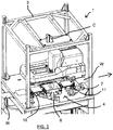
- FIG. 1 A perspective view of a single-lane printing apparatus in accordance with a first embodiment of the present invention is schematically shown in FIG. 1 .
- the printing apparatus 1 comprises a support platform 2 mounted within a frame 3, with the support platform 2 supporting the major components described below.
- a plurality of workpieces W are shown in a single-lane production line, although for clarity conveyor belts which would form the production line are omitted from FIG. 1 .
- workpieces W are conveyed to the printing apparatus 1 from the left side, are printed by the apparatus, and then are conveyed out to the right, following the direction of the arrow shown.
- each workpiece W After being conveyed into the printing apparatus 1, each workpiece W is sequentially conveyed to a loading position or zone L, ready for transport to a printing position or zone P by transfer apparatus 4, as will be described in detail below.
- a printing unit 5 is provided within the printing apparatus 1, supported by the support platform 2, for printing onto a respective workpiece W when in the printing position P.
- the printing unit 5 shown here is of a standard type known in the art, which during a printing operation causes conductive paste to be dispensed, "flooded" onto a printing screen and then applied to a workpiece W using a print head with a squeegee (not shown) which is aligned by print head alignment actuators under the control of a print head X,Y, ⁇ alignment control means (not shown) and driven by print head actuators to move across the upper surface of a printing screen (not shown) in a printing direction.
- the conductive paste is forced through an image of apertures in the screen and onto a workpiece W located underneath the screen, forming a printing pattern corresponding to the screen image.
- the workpiece W may be returned to the loading position L by the transfer apparatus 4, for onward conveyance along the production line.
- An optical inspection apparatus including an optical camera C, which is known in the art per se, is provided on the frame 3 above the loading position L, communicatively connected with the print head X,Y, ⁇ alignment control means. The inspection apparatus is thereby able to inspect the alignment of workpieces W at the loading position L both before and after printing. In particular, the inspection apparatus is able to determine the rotational alignment of a workpiece W at the loading position L. This feature will be discussed in further detail below.
- the inspection apparatus may also be configured to inspect the print quality of the printed workpiece.
- upwardly-directed cameras UC1, UC2 are provided below the printing position P to illuminate and inspect fiducials on the printing screen in use. The use of such cameras is known per se, and their location may be selected as appropriate.
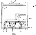
- FIG. 2 schematically shows a side view of the printing apparatus of FIG. 1
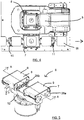
- FIG. 3 shows a perspective view of the printing unit 5 and transfer apparatus 4
- FIG. 4 shows a view of the same from above.
- the transfer apparatus 4 includes a rotary table 6 which supports a first rotatable platen 7 shown at the loading position L and a second rotatable platen 8 located at the printing position P.
- Each platen 7, 8 comprises a belt 9 for supporting a workpiece W thereupon.
- the belt 9 is formed as a paper roll.
- the belt 9 is drivable to move a workpiece W thereon, both to transport the workpiece to and from the production line, as will be described in more detail below, and also to provide for lateral alignment of the workpiece on the respective platen 7, 8.
- a first feed conveyor 10 is positioned proximate the loading position L which receives workpieces W from the upstream production line at an input thereof, for transporting the workpieces to the platen 7 currently at the loading position L.
- a second feed conveyor 11 is positioned proximate the loading position L, for transporting workpieces W from the platen 7 currently at the loading position L to the downstream production line at an output thereof. This means that in this embodiment, the loading position L is located in-line between the input and the output.
- the printing apparatus 1 further comprises means for effecting relative vertical movement between the rotary table 6 and each feed conveyor 10, 11.
- the first and second feed conveyors 10, 11 are movable in the vertical direction (conventionally denoted the "Z" direction), as will be described further below.
- the printing apparatus is configured to form a "T-stub" arrangement with the production line, i.e. the input and output directions of workpieces are co-linear, and workpieces are taken out of the line for printing before being returned to it.
- This arrangement is particularly compact, and easily administered by operators.
- FIG. 5 schematically shows a perspective view of the rotary table 6 in isolation, with a side view thereof schematically shown in FIG. 6 and a sectional view thereof, taken along the line A-A, schematically shown in FIG. 7 .
- the rotary table 6 takes the form of an arm 12, with the first and second rotatable platens 7, 8 fixed respectively in spatially separated locations at opposite ends of the arm 12.
- a hollow central hub 15 mounted for rotation, via supporting bearings 20 with respect to a stationary support 24.
- An arm motor 13 is located within stationary support 24, underneath the hub 15, for producing rotary motion of the arm 12 about a vertical table rotation axis 16 orthogonal to the length of the arm 12 (which axis may be referred to as the "sun axis").
- This rotary motion is controlled using an arm encoder having an arm encoder ring 14 mounted about the hub 15, with electrical power for the arm encoder being supplied via wires 25 passing up through hub 15.
- the arm motor 13 may be located in an offset location, and transmission means such as gearing and / or drive belts or chains provided to effect rotation of the arm about the vertical table rotation axis 16.
- Each platen 7, 8 takes the general form of an inverted container, having a flat upper surface 22a, 22b and opposing dependent sidewalls 27a, 27c for the first platen 7 and 27b, 27d for the second platen 8.
- Each platen is supported on a respective stem 19a, 19b rotatably mounted at ends of the arm 12. Bearings 26a, 26b located at the upper and lower ends of respective stems 19a, 19b allow for the rotation of the stems 19a, 19b, and hence platen 7, 8, with respect to the arm 12.
- Each platen 7, 8 has a respective independent platen motor 17a, 17b drivingly connected to respective stem 19a, 19b and a platen encoder 18a, 18b mounted on the stem 19a, 19b for producing and controlling rotary motion of the respective stem 19a, 19b, and hence platen 7, 8, about a respective vertical axis 21a, 21b ("platen rotation axis" or “moon axis") parallel to the table rotation axis 16, so that each platen 7, 8 is independently rotatable relative to the rotary table 6.
- Electrical power for the platen motors and encoders 17a, b, 18a, b is provided by electrical wires 25 which are fed through hub 15.
- each platen 7, 8 includes means to feed a workpiece W on and off the platen via a belt 9 in the form of a reciprocating paper roll, though other materials and arrangements can be used, including endless belts.
- a first depending sidewall 27a, 27b of each platen 7, 8 supports a respective paper belt motor 28a, 28b, while an opposing depending sidewall 27c, 27d supports a respective paper roller 29a, 29b.
- Actuation of the paper belt motors 28a, 28b is controlled by an internal control chip (not shown) in communication with respective paper belt encoders (not shown) located proximate the paper belt motors. Power for the paper belt motors is supplied via wires 25.
- Each platen 7, 8 is provided with a controllable vacuum source provided via a vacuum feed tube 23 opening in communication with the belt 9, passing through hub 15 and supplying vacuum via a remote source (not shown) connected at its distal end.
- the paper belts 9 are porous, such that the applied vacuum may selectively constrain a workpiece W to the belt 9 to prevent slippage.
- the arm motor 13 is operable to cause the arm 12 to reciprocate through approximately 180° between two fixed stops (not shown). In other embodiments, the arm motor 13 may be operable instead to continue to rotate the arm 12 a full 360° or alternatively to provide a continuous range of rotation.
- the reciprocal arrangement is preferred, since the provision of fixed stops allows for accurate and repeatable positioning of the arm 12.
- a 360° or greater range of motion on the other hand would require the use of moving stops, which are more complex to implement, and furthermore may involve tangling of wires within the central hub of the arm unless a complex rotary joint is employed.
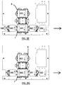
- FIG. 8A schematically shows a side view of the transfer apparatus 4 with the feed conveyors 10, 11 in a lowered state.
- Feed conveyors 10, 11 are similarly constructed, each having an axially extending support tower 46, which supports a looped continuous conveyor belt 47 mounted on rollers 48 at each end thereof.
- Each conveyor belt 47 is driven by a respective driving means 49, operable to rotate at least one roller 48 and hence the supported belt 47.
- the upper surface of each conveyor belt 47 is configured for supporting a workpiece W thereon.
- a vacuum source (not shown) may be connected to each belt 47, to constrain a supported workpiece W thereto to prevent slippage.
- each support tower 46 is axially extendable, i.e.
- FIG. 8A the towers are shown in their retracted or lowered state, in which state the upper surfaces of conveyor belts 47 are substantially co-planar with the upper surface of platen 7, so that workpieces W may be transferred between platen 7 and the conveyor belts 47 safely, without excessive bending strain being applied thereto.
- each conveyor belt 47 has its inner end in close proximity to platen 7, which again is advantageous to avoid unwanted application of bending strain to the workpiece W.
- this close proximity also means that rotation of the rotary table 6 while the feed conveyors 10, 11 are in this state would cause the platen 7 and the feed conveyors 10, 11 to collide.
- FIG. 8B schematically shows a side view similar to that of FIG. 8A , but with the feed conveyors in a raised state, due to suitable actuation of the linear drive means.
- the support towers 46 are extended, such that the lower surface of conveyor belts 47 are at a higher vertical level than the upper surface of platen 7.
- the rotary table 6 may rotate freely, without impacting the feed conveyors 10, 11.
- the operation of the printing apparatus 1, including the controlled actuation of arm and platen drive means, conveyor belt and platen belt driving, vacuum actuation and release, the printing operation and inspection are all controlled by a control means (not shown), such as a remotely-located processing means, preferably a computer with dedicated control software installed.
- a control means such as a remotely-located processing means, preferably a computer with dedicated control software installed.
- each workpiece W is shown with an arrow thereon, which arrow will remain fixed in orientation with respect to that workpiece.
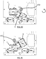
- FIG. 9A schematically shows from above the printing apparatus 1 at a representative point in the printing procedure.
- First platen 7 is positioned at the loading position L, while second platen 8 is positioned at printing position P.
- a first workpiece W1 has been loaded onto first platen 7 from feed conveyor 10, in turn from the upstream production line.
- a second workpiece W2 is supported on second platen 8, at the printing position P, which workpiece W2 has just been printed.
- a third workpiece W3 is located on feed conveyor 10, having been received from the upstream production line.
- a fourth workpiece W4 is located on feed conveyor 11, for subsequent transfer to the downstream production line.
- the feed conveyors 10, 11 are in their lowered state, since loading of workpiece W1 onto first platen 7 and unloading of workpiece W4 from first platen 7 has only just occurred.
- camera C is used to capture an image of W1.
- This image provides alignment information for W1, which is sent to the print head X,Y, ⁇ alignment control means, causing the print head alignment actuators to start moving to the latest alignment position so that the incoming workpiece and screen print image will be aligned and ready to print (in practice this alignment movement is completed during the following arm rotation).
- feed conveyors 10, 11 are raised up to their raised state.
- FIG. 9B the commencement of a first movement operation is shown from above, in which the rotary table 6 is caused to move in a clockwise rotational direction as shown, following completion of the printing of workpiece W2.
- platen 7 may safely travel from loading position L, towards printing position P, underneath input feed conveyor 10 since it is in its raised state.
- First platen 7, and workpiece W1 supported thereon may remain at a fixed angle with respect to the arm 12 during this movement.
- the first platen 7 may be rotated, during this arm rotation, as required e.g. for vector printing or error correction of the workpiece W1, by selective actuation of first platen motor 17, using first platen encoder 19, under the control of the control means.
- second platen 8 With printed workpiece W2 supported thereon, moves from printing position P towards loading position L.
- the second platen 8 rotates relative both to arm 12 and first platen 7, this rotation being effected by the second platen motor 18, and controlled using second platen encoder 20.
- its absolute orientation, or rotational position relative to support platform 2 remains substantially unchanged. In this way the printed workpiece W2 is rotated around the platen axis by 180°, with the required driving direction of the belt 9 when loading and unloading the next workpiece reversed accordingly.
- the flood stroke takes place, in which the printing screen is flooded with conductive paste.
- upwardly-looking camera UC2 may illuminate and inspect fiducials of the printing screen.
- the feed conveyors 10, 11 are lowered as soon as second platen 8 passes to the loading position L.
- FIG. 9C which shows from above the arrangement at the end of the first movement operation, second platen 8 with printed workpiece W2 thereon has arrived at the loading position L, while first platen 7 with workpiece W1 thereon has arrived at the printing position P.
- Printing of W1 commences when the correct orientation of workpiece W1 has been obtained, which as set out above will, barring a fault, have been completed during the first movement operation.
- workpiece W4 is conveyed to the downstream production line
- printed workpiece W2 is unloaded from second platen 8 to second feed conveyor 11
- workpiece W3 is loaded onto second platen 8 from first feed conveyor 10, through driving of the second platen belt 9 and feed conveyors 10, 11.
- the unloading of the printed workpiece W2 and loading the next workpiece W3 happen concurrently.
- the belt 9 of the second platen 8 is rotated a set distance, for example by approximately the dimension of two workpieces, in a first direction.
- a further workpiece W5 is conveyed onto first feed conveyor 10 from the production line.
- workpiece W3 is in the field of view of the optical inspection system.
- the trailing edge of the workpiece W3 is determined as it leaves the feed conveyor 10, at which time most of the workpiece W3 is on the second platen 8 and under vacuum control required to prevent any slippage due to its motion profile.
- a landed position of less than about 1mm out of position may be achieved using this technique. The closer the landed position is to the actual alignment position, the better the accuracy of the final print and the better the cycle time.
- the workpiece W3 stopped in the desired position its alignment is captured optically by the inspection system, either by identifying the edges of the workpiece W3 or by identifying alignment points previously marked on the front surface of the workpiece. In alternative embodiments it is also possible to use a previously-printed workpiece as the alignment target.
- the input and output feed conveyors 10, 11 are again raised and the print head alignment actuators move to the latest alignment position so that the incoming workpiece and screen print image will be aligned and ready to print.
- FIGs. 9D and 9E schematically show, from above, the printing apparatus 1 at two successive instances after commencement of this second movement operation, in which in FIG. 9D the second platen 8 is passing underneath output feed conveyor 11, while in FIG. 9E the second platen 8 has cleared output feed conveyor 11 but first platen 7 is passing underneath raised input feed conveyor 10.
- Second platen 8, and workpiece W3 supported thereon may remain at a fixed angle with respect to the arm 12 during this movement.
- the second platen 8 may be rotated, during this arm rotation, as required e.g. for vector printing or error correction of the workpiece W3, by selective actuation of second platen motor 18, using second platen encoder 20, under the control of the control means.
- first platen 7, with printed workpiece W1 supported thereon moves from printing position P towards loading position L.
- the first platen 7 rotates relative both to arm 12 and second platen 8, this rotation being effected by the first platen motor 17, and controlled using first platen encoder 19.
- its absolute orientation, or rotational position relative to support platform 2 remains substantially unchanged. In this way the printed workpiece W1 is rotated around the platen axis by 180°, with the required driving direction of the first platen's belt 9 when loading and unloading the next workpiece reversed accordingly.
- the flood stroke takes place, in which the printing screen is flooded with conductive paste.
- upwardly-looking camera UC1 may illuminate and inspect fiducials of the printing screen.
- the feed conveyors 10, 11 are lowered as soon as first platen 7 passes to the loading position L.
- FIG. 9F which shows from above the arrangement at the end of the second movement operation, first platen 7 with printed workpiece W1 thereon has arrived at the loading position L, while second platen 8 with workpiece W3 thereon has arrived at the printing position P.
- Printing of W3 commences when the correct orientation of workpiece W3 has been obtained, which as set out above will, barring a fault, have been completed during the second movement operation.
- workpiece W2 is conveyed to the downstream production line, printed workpiece W1 is unloaded from first platen 7 to second feed conveyor 11, and workpiece W5 is loaded onto first platen 7 from first feed conveyor 10, through driving of the first platen belt 9 and feed conveyors 10, 11.
- the unloading of the printed workpiece W1 and loading the next workpiece W5 happen concurrently.
- the belt 9 of the first platen 7 is rotated a set distance, for example by approximately the dimension of two workpieces, in a first direction.
- FIG. 9G schematically shows from above the arrangement following this parallel printing and loading / unloading step.
- FIG. 9G is therefore analogous to FIG. 9A , and thereafter the above-described steps are repeatedly cyclically.
- FIGs. 9A and 9G show that while the platens 7, 8 have returned to their original locations, they are both rotated by 180°. This means that consecutive loading / unloading steps for each platen involves driving the associated belt in different directions. Therefore it is not necessary to use an endless belt, and a much simpler reciprocating belt arrangement may be used instead.
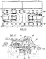
- FIG. 10 schematically shows a second embodiment of the present invention from above.
- a dual-lane printing arrangement is configured, using two separate printing apparatuses 30, 31.
- Each printing apparatus 30, 31 is substantially similar to the printing apparatus 1 of FIG. 1 , and need not be described in detail.
- the arrangement shown provides for two separate production lanes 32, 33, with each lane feeding workpieces from left to right as shown.
- the printing apparatuses 30, 31 are arranged in a face-to face configuration, i.e. so that their respective support platforms and frames are adjacent but one apparatus 31 is rotated 180° relative to the other apparatus 30.
- each printing apparatus 30, 31 is arranged to print workpieces provided by different respective production lanes 32, 33, with apparatus 30 arranged to print workpieces from production lane 32, and apparatus 31 arranged to print workpieces from production lane 33.
- the compact "T-stub" arrangement of FIG. 4 is retained, with each stub associated with a respective production lane. It will be noted that the workpieces of production lane 32 will arrive at their respective printing apparatus and thus be printed before their counterparts on production lane 33, however the cycle time is unaffected by this discrepancy.
- the "T-stub" arrangement ensures that the distance between production lanes 32, 33 is relatively short, leading to a compact arrangement which is easily administered by operators.
- FIG. 11 schematically shows a perspective view of a printing apparatus in accordance with a third embodiment of the present invention, using an offset production lane.
- the transfer apparatus and printing unit are largely unchanged from the first embodiment, however the workpiece production line feed is now in an offset arrangement, such that the workpiece input direction and workpiece output direction are no longer co-linear.
- the input feed conveyor 40 used here is substantially L-shaped, comprising an input feed first belt 41 arranged parallel to the upstream production line for co-operation therewith, and an input feed second belt 42 arranged orthogonally to the production line, which receives workpieces from input feed first belt 41 and loads workpieces to the loading position.
- the output feed conveyor 43 used here is also substantially L-shaped, comprising an output feed first belt 44 arranged orthogonally to the production line, which unloads workpieces from the loading position L', and an output feed second belt 45 arranged parallel to the downstream production line for receiving workpieces from belt 44 and feeding them to the downstream production line.
- This arrangement is not as compact as the previously-described "T-stub" arrangements, but may be preferred in certain locations.
- FIG. 12 schematically shows a perspective view of a transfer apparatus 51, using endless belts.
- FIG. 13 meanwhile shows a side view of this transfer apparatus.
- This apparatus has many similarities with that of the first embodiment shown in FIGs. 1 to 9 , such as the use of a two-platen rotary table to move workpieces between a loading position and printing position, together with the use of vertically-movable feed conveyors and therefore in particular retains the compact "T-stub" configuration of that embodiment.
- no means are provided to enable either platen to rotate relative either to the arm or the other platen.
- transfer apparatus 51 includes a rotary table in the form of an arm 52.
- a platen 53a, 53b is mounted at each end of arm 52, each platen 53a, 53b being incapable of rotation with respect to the arm 52.
- Each platen 53a, 53b is provided with a respective endless or continuous paper belt 54a, 54b.
- Each belt 54a, 54b is mounted on respective rollers 55a, 56a, 55b, 56b located at the ends of the platens.
- a first roller 55a, 55b of each platen 53a, 53b has a circumferentially-toothed end 57a, 57b.
- Respective belt drive actuators 58a, 58b, mounted on arm 52, are operative to rotatably drive output gears 59a (not visible in FIG. 12 ), 59b, which mesh with the toothed ends 57a, 57b to cause them to rotate as required.
- a control chip (not shown) is provided within the transfer apparatus 51 to effect control of these actuators 58a, 58b.
- Each belt is porous, such that a vacuum can be applied to a workpiece (not shown) located on the top of the platen, to prevent unwanted movement thereof.
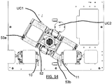
- FIG. 14 schematically shows a plan view of the transfer apparatus of FIG. 12 , during a loading operation. It should be noted that the operation has many similarities with that of the first embodiment, and like reference numerals are retained where possible.
- first and second feed conveyors 10, 11 are again provided adjacent to a loading position, and these feed conveyors are moveable in the vertical direction to enable the arm 52 and platens 53a, 53b to pass underneath during transfer of workpieces between the loading and printing positions.
- Upwardly-directed cameras UC1, UC2 are located proximate a printing position.
- FIG. 14 clarifies that since neither platen 53a, 53b can rotate relative to the arm 52, each workpiece must be loaded onto a platen, and unloaded off the platen in the same direction, i.e. left to right as shown. This in turn means that the belt 54a, 54b of each platen 53a, 53b must be driveable in the same direction for both loading and unloading operations, and hence the use of continuous belts is preferred.
- the rotary table may rotate in either direction during either of the first and second movement operations.
Landscapes
- Engineering & Computer Science (AREA)
- Mechanical Engineering (AREA)
- Manufacturing & Machinery (AREA)
- Microelectronics & Electronic Packaging (AREA)
- Screen Printers (AREA)
- Handling Of Sheets (AREA)
- Container, Conveyance, Adherence, Positioning, Of Wafer (AREA)
- Specific Conveyance Elements (AREA)
Priority Applications (1)
| Application Number | Priority Date | Filing Date | Title |
|---|---|---|---|
| PL18000455T PL3403828T3 (pl) | 2017-05-16 | 2018-05-14 | Przemieszczanie i drukowanie przedmiotu obrabianego |
Applications Claiming Priority (1)
| Application Number | Priority Date | Filing Date | Title |
|---|---|---|---|
| GB1707878.3A GB2562503A (en) | 2017-05-16 | 2017-05-16 | Workpiece transfer and printing |
Publications (2)
| Publication Number | Publication Date |
|---|---|
| EP3403828A1 EP3403828A1 (en) | 2018-11-21 |
| EP3403828B1 true EP3403828B1 (en) | 2021-12-15 |
Family
ID=59201441
Family Applications (1)
| Application Number | Title | Priority Date | Filing Date |
|---|---|---|---|
| EP18000455.8A Active EP3403828B1 (en) | 2017-05-16 | 2018-05-14 | Workpiece transfer and printing |
Country Status (9)
| Country | Link |
|---|---|
| US (1) | US10986736B2 (pl) |
| EP (1) | EP3403828B1 (pl) |
| JP (1) | JP6626923B2 (pl) |
| KR (1) | KR102082107B1 (pl) |
| CN (1) | CN108878334B (pl) |
| GB (1) | GB2562503A (pl) |
| PL (1) | PL3403828T3 (pl) |
| SG (1) | SG10201802873QA (pl) |
| TW (1) | TWI702151B (pl) |
Cited By (2)
| Publication number | Priority date | Publication date | Assignee | Title |
|---|---|---|---|---|
| CN116353192A (zh) * | 2023-03-20 | 2023-06-30 | 杭州余杭獐山钢瓶有限公司 | 一种钢瓶自动印刷机 |
| WO2024211422A1 (en) * | 2023-04-03 | 2024-10-10 | Sonix, Inc. | Multi-holder inspection system using moveable support structure |
Families Citing this family (15)
| Publication number | Priority date | Publication date | Assignee | Title |
|---|---|---|---|---|
| CN107458088B (zh) * | 2017-08-16 | 2024-06-14 | 深圳市深龙杰科技有限公司 | 一种双工位全自动产品图文打印机 |
| GB2580347A (en) * | 2019-01-03 | 2020-07-22 | Asm Assembly Systems Singapore Pte Ltd | Alignment of singulated workpieces |
| CN111516384A (zh) * | 2019-02-01 | 2020-08-11 | 湖南华庆科技有限公司 | 一种光学膜片生产设备及方法 |
| HUE065483T2 (hu) * | 2019-04-18 | 2024-05-28 | Exentis Knowledge Gmbh | Berendezés és eljárás háromdimenziós szitanyomó munkadarabok elõállítására |
| ES2988515T3 (es) | 2019-04-18 | 2024-11-20 | Exentis Knowledge Gmbh | Procedimiento para la fabricación de piezas de trabajo de serigrafía tridimensionales |
| PT3725523T (pt) | 2019-04-18 | 2024-05-02 | Exentis Knowledge Gmbh | Dispositivo e método para a produção de peças serigrafadas tridimensionais |
| CN110047786B (zh) * | 2019-04-26 | 2024-07-05 | 无锡奥特维科技股份有限公司 | 导电胶涂覆装置及叠片组件生产装置 |
| CN110060946B (zh) * | 2019-04-26 | 2024-08-02 | 无锡奥特维科技股份有限公司 | 双工位导电胶涂覆装置及叠片组件生产装置 |
| CN110867404A (zh) * | 2019-09-30 | 2020-03-06 | 正信光电科技股份有限公司 | 光伏组件生产用零部件输送带 |
| KR102253792B1 (ko) * | 2019-12-27 | 2021-05-20 | 주식회사 엘에이티 | 듀얼 스테이지 유닛 및 이를 포함하는 웨이퍼 로딩/언로딩 장치, 그리고 이를 이용한 웨이퍼 로딩/언로딩 방법 |
| CN112848652A (zh) * | 2021-01-02 | 2021-05-28 | 蔡宗新 | 一种陶瓷高精度自动印花设备及其工艺 |
| DE102021205984A1 (de) * | 2021-06-11 | 2022-12-15 | Ekra Automatisierungssysteme Gmbh | Druckvorrichtung und Verfahren zum Bedrucken von Substraten |
| US12275232B1 (en) * | 2022-03-08 | 2025-04-15 | Applied Materials Italia S.R.L. | Method of dispensing paste for a printer using a paste dispensing apparatus and paste dispensing apparatus for dispensing paste for a printer |
| CN115042510B (zh) * | 2022-07-25 | 2023-08-08 | 丰县通亚电子科技有限公司 | 一种电动车塑件生产用热转印机 |
| KR102723660B1 (ko) * | 2022-08-29 | 2024-10-29 | 조성천 | 태양광패널 프린팅장치 |
Family Cites Families (25)
| Publication number | Priority date | Publication date | Assignee | Title |
|---|---|---|---|---|
| US4386864A (en) * | 1980-11-04 | 1983-06-07 | Wang Laboratories, Inc. | Selective paper insertion and feeding means for individual sheet printing apparatus |
| US4974508A (en) * | 1989-03-08 | 1990-12-04 | Andersen Edward A | Screen printing apparatus |
| JP2560146B2 (ja) * | 1990-11-30 | 1996-12-04 | 株式会社新興製作所 | プラテン位置決め装置 |
| US5592877A (en) * | 1995-10-25 | 1997-01-14 | Elexon Ltd. | Screen printing apparatus with data storage |
| JPH1110832A (ja) * | 1997-06-23 | 1999-01-19 | Ibiden Co Ltd | 自動作業装置 |
| US6732855B1 (en) * | 2000-09-08 | 2004-05-11 | Motorola, Inc. | Conveying element and conveyor means for conveying wafer receptacles, and method |
| JP2002225221A (ja) * | 2001-02-02 | 2002-08-14 | Matsushita Electric Ind Co Ltd | スクリーン印刷機及びスクリーン印刷方法 |
| TWI348450B (en) * | 2003-11-13 | 2011-09-11 | Applied Materials Inc | Break-away positioning conveyor mount for accommodating conveyor belt bends |
| JP5023904B2 (ja) * | 2007-09-11 | 2012-09-12 | パナソニック株式会社 | スクリーン印刷装置 |
| ITUD20070198A1 (it) * | 2007-10-24 | 2009-04-25 | Baccini S P A | Dispositivo di posizionamento per posizionare una o piu' piastre di circuiti elettronici, in un'unita' di deposizione del metallo, e relativo procedimento |
| US8215473B2 (en) * | 2008-05-21 | 2012-07-10 | Applied Materials, Inc. | Next generation screen printing system |
| US20090308860A1 (en) * | 2008-06-11 | 2009-12-17 | Applied Materials, Inc. | Short thermal profile oven useful for screen printing |
| JP5511273B2 (ja) * | 2008-09-12 | 2014-06-04 | 株式会社日立国際電気 | 基板処理装置及び基板処理方法 |
| JP4545230B1 (ja) * | 2010-01-26 | 2010-09-15 | 智雄 松下 | パターン形成装置 |
| KR101144769B1 (ko) * | 2010-04-08 | 2012-05-11 | (유)에스엔티 | 스크린 프린팅 시스템 |
| US9032872B2 (en) | 2010-07-23 | 2015-05-19 | Plastipak Packaging, Inc. | Rotary system and method for printing containers |
| IT1402241B1 (it) * | 2010-09-13 | 2013-08-28 | Applied Materials Inc | Unita' per il trasporto di un supporto di stampa in un impianto per la deposizione di tracce di stampa su tale supporto di stampa, e relativo procedimento per il trasporto |
| US9757963B2 (en) * | 2010-11-01 | 2017-09-12 | Scodix Ltd. | System and method for transporting substrates |
| JP5597595B2 (ja) * | 2011-05-31 | 2014-10-01 | ヤマハ発動機株式会社 | スクリーン印刷装置 |
| JP6124249B2 (ja) * | 2012-08-16 | 2017-05-10 | Jukiオートメーションシステムズ株式会社 | スクリーン印刷装置、印刷物の製造方法及び基板の製造方法 |
| US9315012B2 (en) * | 2013-10-22 | 2016-04-19 | M&R Printing Equipment, Inc. | Screen printing pallet assembly and method of using pallet assembly in a screen printing operation |
| EP2918410A1 (en) * | 2014-03-10 | 2015-09-16 | Applied Materials Italia S.R.L. | Rotary table and solar cell processing system |
| KR101605077B1 (ko) * | 2014-03-10 | 2016-04-04 | (주)예스티 | 웨이퍼 상에 칩을 정밀하게 본딩하기 위한 장치 |
| JP2017064743A (ja) * | 2015-09-29 | 2017-04-06 | 株式会社ディスコ | レーザー加工装置 |
| CN105835522B (zh) | 2016-05-26 | 2018-08-24 | 东莞市展迅机械科技有限公司 | 一种旋转式快速印刷机 |
-
2017
- 2017-05-16 GB GB1707878.3A patent/GB2562503A/en not_active Withdrawn
-
2018
- 2018-03-30 US US15/941,083 patent/US10986736B2/en active Active
- 2018-03-31 TW TW107111423A patent/TWI702151B/zh active
- 2018-04-05 SG SG10201802873QA patent/SG10201802873QA/en unknown
- 2018-04-27 KR KR1020180048938A patent/KR102082107B1/ko not_active Expired - Fee Related
- 2018-05-14 CN CN201810455869.3A patent/CN108878334B/zh active Active
- 2018-05-14 PL PL18000455T patent/PL3403828T3/pl unknown
- 2018-05-14 EP EP18000455.8A patent/EP3403828B1/en active Active
- 2018-05-15 JP JP2018093605A patent/JP6626923B2/ja active Active
Non-Patent Citations (1)
| Title |
|---|
| None * |
Cited By (3)
| Publication number | Priority date | Publication date | Assignee | Title |
|---|---|---|---|---|
| CN116353192A (zh) * | 2023-03-20 | 2023-06-30 | 杭州余杭獐山钢瓶有限公司 | 一种钢瓶自动印刷机 |
| CN116353192B (zh) * | 2023-03-20 | 2023-11-21 | 杭州余杭獐山钢瓶有限公司 | 一种钢瓶自动印刷机 |
| WO2024211422A1 (en) * | 2023-04-03 | 2024-10-10 | Sonix, Inc. | Multi-holder inspection system using moveable support structure |
Also Published As
| Publication number | Publication date |
|---|---|
| CN108878334B (zh) | 2023-05-09 |
| CN108878334A (zh) | 2018-11-23 |
| JP2018195821A (ja) | 2018-12-06 |
| JP6626923B2 (ja) | 2019-12-25 |
| GB201707878D0 (en) | 2017-06-28 |
| KR20180125883A (ko) | 2018-11-26 |
| GB2562503A (en) | 2018-11-21 |
| PL3403828T3 (pl) | 2022-04-19 |
| US20180338378A1 (en) | 2018-11-22 |
| TW201900428A (zh) | 2019-01-01 |
| EP3403828A1 (en) | 2018-11-21 |
| US10986736B2 (en) | 2021-04-20 |
| HK1257251A1 (zh) | 2019-10-18 |
| SG10201802873QA (en) | 2018-12-28 |
| KR102082107B1 (ko) | 2020-02-28 |
| TWI702151B (zh) | 2020-08-21 |
Similar Documents
| Publication | Publication Date | Title |
|---|---|---|
| EP3403828B1 (en) | Workpiece transfer and printing | |
| EP2185362B1 (en) | Workpiece processing system and method | |
| US8215473B2 (en) | Next generation screen printing system | |
| CN103619595B (zh) | 网版印刷装置 | |
| US9484234B2 (en) | Processing station for planar substrates and method for processing planar substrates | |
| KR20080048814A (ko) | 웨이퍼이송장치 | |
| CN112693245B (zh) | 电池片印刷方法 | |
| CN113561630A (zh) | 一种用于太阳能电池的印刷装置 | |
| JP3879679B2 (ja) | 電子部品搭載装置および電子部品搭載方法 | |
| JP5530170B2 (ja) | スクリーン印刷装置 | |
| CN103619594A (zh) | 网版印刷装置 | |
| KR101300853B1 (ko) | 기판 반송 시스템, 기판 반송 장치 및 기판 처리 장치 | |
| JP2009135554A (ja) | 部品実装装置 | |
| HK1257251B (en) | Workpiece transfer and printing | |
| JP2002127064A (ja) | 電子部品用自動ハンドリング装置 | |
| JP5536438B2 (ja) | スクリーン印刷装置 | |
| TW201835986A (zh) | 印刷設備 | |
| JP2001313492A (ja) | 部品実装システム | |
| KR101902844B1 (ko) | 스크린인쇄법을 이용한 피스톤 도막 형성시스템 | |
| EP4295416A1 (en) | Transportation system for transporting two or more substrates, printing apparatus for printing on two or more substrates, and methods for performing same | |
| JP2007227617A (ja) | 表面実装機および実装ライン | |
| JP6843115B2 (ja) | はんだ印刷機 | |
| CN113696618A (zh) | 印制设备 | |
| JPH03297160A (ja) | 姿勢矯正装置 | |
| HK1143964B (en) | Workpiece processing system and method |
Legal Events
| Date | Code | Title | Description |
|---|---|---|---|
| PUAI | Public reference made under article 153(3) epc to a published international application that has entered the european phase |
Free format text: ORIGINAL CODE: 0009012 |
|
| STAA | Information on the status of an ep patent application or granted ep patent |
Free format text: STATUS: THE APPLICATION HAS BEEN PUBLISHED |
|
| AK | Designated contracting states |
Kind code of ref document: A1 Designated state(s): AL AT BE BG CH CY CZ DE DK EE ES FI FR GB GR HR HU IE IS IT LI LT LU LV MC MK MT NL NO PL PT RO RS SE SI SK SM TR |
|
| AX | Request for extension of the european patent |
Extension state: BA ME |
|
| STAA | Information on the status of an ep patent application or granted ep patent |
Free format text: STATUS: REQUEST FOR EXAMINATION WAS MADE |
|
| 17P | Request for examination filed |
Effective date: 20190515 |
|
| RBV | Designated contracting states (corrected) |
Designated state(s): AL AT BE BG CH CY CZ DE DK EE ES FI FR GB GR HR HU IE IS IT LI LT LU LV MC MK MT NL NO PL PT RO RS SE SI SK SM TR |
|
| STAA | Information on the status of an ep patent application or granted ep patent |
Free format text: STATUS: EXAMINATION IS IN PROGRESS |
|
| 17Q | First examination report despatched |
Effective date: 20201020 |
|
| GRAP | Despatch of communication of intention to grant a patent |
Free format text: ORIGINAL CODE: EPIDOSNIGR1 |
|
| STAA | Information on the status of an ep patent application or granted ep patent |
Free format text: STATUS: GRANT OF PATENT IS INTENDED |
|
| INTG | Intention to grant announced |
Effective date: 20210705 |
|
| GRAS | Grant fee paid |
Free format text: ORIGINAL CODE: EPIDOSNIGR3 |
|
| GRAA | (expected) grant |
Free format text: ORIGINAL CODE: 0009210 |
|
| STAA | Information on the status of an ep patent application or granted ep patent |
Free format text: STATUS: THE PATENT HAS BEEN GRANTED |
|
| AK | Designated contracting states |
Kind code of ref document: B1 Designated state(s): AL AT BE BG CH CY CZ DE DK EE ES FI FR GB GR HR HU IE IS IT LI LT LU LV MC MK MT NL NO PL PT RO RS SE SI SK SM TR |
|
| REG | Reference to a national code |
Ref country code: GB Ref legal event code: FG4D Ref country code: CH Ref legal event code: EP |
|
| REG | Reference to a national code |
Ref country code: DE Ref legal event code: R096 Ref document number: 602018028063 Country of ref document: DE |
|
| REG | Reference to a national code |
Ref country code: IE Ref legal event code: FG4D |
|
| REG | Reference to a national code |
Ref country code: AT Ref legal event code: REF Ref document number: 1455201 Country of ref document: AT Kind code of ref document: T Effective date: 20220115 |
|
| REG | Reference to a national code |
Ref country code: NL Ref legal event code: FP |
|
| REG | Reference to a national code |
Ref country code: LT Ref legal event code: MG9D |
|
| PG25 | Lapsed in a contracting state [announced via postgrant information from national office to epo] |
Ref country code: RS Free format text: LAPSE BECAUSE OF FAILURE TO SUBMIT A TRANSLATION OF THE DESCRIPTION OR TO PAY THE FEE WITHIN THE PRESCRIBED TIME-LIMIT Effective date: 20211215 Ref country code: LT Free format text: LAPSE BECAUSE OF FAILURE TO SUBMIT A TRANSLATION OF THE DESCRIPTION OR TO PAY THE FEE WITHIN THE PRESCRIBED TIME-LIMIT Effective date: 20211215 Ref country code: FI Free format text: LAPSE BECAUSE OF FAILURE TO SUBMIT A TRANSLATION OF THE DESCRIPTION OR TO PAY THE FEE WITHIN THE PRESCRIBED TIME-LIMIT Effective date: 20211215 Ref country code: BG Free format text: LAPSE BECAUSE OF FAILURE TO SUBMIT A TRANSLATION OF THE DESCRIPTION OR TO PAY THE FEE WITHIN THE PRESCRIBED TIME-LIMIT Effective date: 20220315 |
|
| PG25 | Lapsed in a contracting state [announced via postgrant information from national office to epo] |
Ref country code: SE Free format text: LAPSE BECAUSE OF FAILURE TO SUBMIT A TRANSLATION OF THE DESCRIPTION OR TO PAY THE FEE WITHIN THE PRESCRIBED TIME-LIMIT Effective date: 20211215 Ref country code: NO Free format text: LAPSE BECAUSE OF FAILURE TO SUBMIT A TRANSLATION OF THE DESCRIPTION OR TO PAY THE FEE WITHIN THE PRESCRIBED TIME-LIMIT Effective date: 20220315 Ref country code: LV Free format text: LAPSE BECAUSE OF FAILURE TO SUBMIT A TRANSLATION OF THE DESCRIPTION OR TO PAY THE FEE WITHIN THE PRESCRIBED TIME-LIMIT Effective date: 20211215 Ref country code: HR Free format text: LAPSE BECAUSE OF FAILURE TO SUBMIT A TRANSLATION OF THE DESCRIPTION OR TO PAY THE FEE WITHIN THE PRESCRIBED TIME-LIMIT Effective date: 20211215 Ref country code: GR Free format text: LAPSE BECAUSE OF FAILURE TO SUBMIT A TRANSLATION OF THE DESCRIPTION OR TO PAY THE FEE WITHIN THE PRESCRIBED TIME-LIMIT Effective date: 20220316 |
|
| PG25 | Lapsed in a contracting state [announced via postgrant information from national office to epo] |
Ref country code: SM Free format text: LAPSE BECAUSE OF FAILURE TO SUBMIT A TRANSLATION OF THE DESCRIPTION OR TO PAY THE FEE WITHIN THE PRESCRIBED TIME-LIMIT Effective date: 20211215 Ref country code: SK Free format text: LAPSE BECAUSE OF FAILURE TO SUBMIT A TRANSLATION OF THE DESCRIPTION OR TO PAY THE FEE WITHIN THE PRESCRIBED TIME-LIMIT Effective date: 20211215 Ref country code: RO Free format text: LAPSE BECAUSE OF FAILURE TO SUBMIT A TRANSLATION OF THE DESCRIPTION OR TO PAY THE FEE WITHIN THE PRESCRIBED TIME-LIMIT Effective date: 20211215 Ref country code: PT Free format text: LAPSE BECAUSE OF FAILURE TO SUBMIT A TRANSLATION OF THE DESCRIPTION OR TO PAY THE FEE WITHIN THE PRESCRIBED TIME-LIMIT Effective date: 20220418 Ref country code: ES Free format text: LAPSE BECAUSE OF FAILURE TO SUBMIT A TRANSLATION OF THE DESCRIPTION OR TO PAY THE FEE WITHIN THE PRESCRIBED TIME-LIMIT Effective date: 20211215 Ref country code: EE Free format text: LAPSE BECAUSE OF FAILURE TO SUBMIT A TRANSLATION OF THE DESCRIPTION OR TO PAY THE FEE WITHIN THE PRESCRIBED TIME-LIMIT Effective date: 20211215 |
|
| REG | Reference to a national code |
Ref country code: DE Ref legal event code: R097 Ref document number: 602018028063 Country of ref document: DE |
|
| PG25 | Lapsed in a contracting state [announced via postgrant information from national office to epo] |
Ref country code: IS Free format text: LAPSE BECAUSE OF FAILURE TO SUBMIT A TRANSLATION OF THE DESCRIPTION OR TO PAY THE FEE WITHIN THE PRESCRIBED TIME-LIMIT Effective date: 20220415 |
|
| PLBE | No opposition filed within time limit |
Free format text: ORIGINAL CODE: 0009261 |
|
| STAA | Information on the status of an ep patent application or granted ep patent |
Free format text: STATUS: NO OPPOSITION FILED WITHIN TIME LIMIT |
|
| PG25 | Lapsed in a contracting state [announced via postgrant information from national office to epo] |
Ref country code: DK Free format text: LAPSE BECAUSE OF FAILURE TO SUBMIT A TRANSLATION OF THE DESCRIPTION OR TO PAY THE FEE WITHIN THE PRESCRIBED TIME-LIMIT Effective date: 20211215 Ref country code: AL Free format text: LAPSE BECAUSE OF FAILURE TO SUBMIT A TRANSLATION OF THE DESCRIPTION OR TO PAY THE FEE WITHIN THE PRESCRIBED TIME-LIMIT Effective date: 20211215 |
|
| 26N | No opposition filed |
Effective date: 20220916 |
|
| PG25 | Lapsed in a contracting state [announced via postgrant information from national office to epo] |
Ref country code: SI Free format text: LAPSE BECAUSE OF FAILURE TO SUBMIT A TRANSLATION OF THE DESCRIPTION OR TO PAY THE FEE WITHIN THE PRESCRIBED TIME-LIMIT Effective date: 20211215 |
|
| REG | Reference to a national code |
Ref country code: BE Ref legal event code: MM Effective date: 20220531 |
|
| PG25 | Lapsed in a contracting state [announced via postgrant information from national office to epo] |
Ref country code: MC Free format text: LAPSE BECAUSE OF FAILURE TO SUBMIT A TRANSLATION OF THE DESCRIPTION OR TO PAY THE FEE WITHIN THE PRESCRIBED TIME-LIMIT Effective date: 20211215 Ref country code: LU Free format text: LAPSE BECAUSE OF NON-PAYMENT OF DUE FEES Effective date: 20220514 |
|
| REG | Reference to a national code |
Ref country code: NL Ref legal event code: HC Owner name: ASMPT SMT SINGAPORE PTE. LTD.; SG Free format text: DETAILS ASSIGNMENT: CHANGE OF OWNER(S), CHANGE OF OWNER(S) NAME; FORMER OWNER NAME: ASM ASSEMBLY SYSTEMS SINGAPORE PTE. LTD. Effective date: 20230130 |
|
| REG | Reference to a national code |
Ref country code: DE Ref legal event code: R081 Ref document number: 602018028063 Country of ref document: DE Owner name: ASMPT SMT SINGAPORE PTE. LTD., SG Free format text: FORMER OWNER: ASM ASSEMBLY SYSTEMS SINGAPORE PTE. LTD., SINGAPUR, SG |
|
| PG25 | Lapsed in a contracting state [announced via postgrant information from national office to epo] |
Ref country code: IE Free format text: LAPSE BECAUSE OF NON-PAYMENT OF DUE FEES Effective date: 20220514 |
|
| PG25 | Lapsed in a contracting state [announced via postgrant information from national office to epo] |
Ref country code: BE Free format text: LAPSE BECAUSE OF NON-PAYMENT OF DUE FEES Effective date: 20220531 |
|
| P01 | Opt-out of the competence of the unified patent court (upc) registered |
Effective date: 20230530 |
|
| REG | Reference to a national code |
Ref country code: AT Ref legal event code: UEP Ref document number: 1455201 Country of ref document: AT Kind code of ref document: T Effective date: 20211215 Ref country code: AT Ref legal event code: HC Ref document number: 1455201 Country of ref document: AT Kind code of ref document: T Owner name: ASMPT SMT SINGAPORE PTE. LTD, SG Effective date: 20231023 |
|
| PG25 | Lapsed in a contracting state [announced via postgrant information from national office to epo] |
Ref country code: HU Free format text: LAPSE BECAUSE OF FAILURE TO SUBMIT A TRANSLATION OF THE DESCRIPTION OR TO PAY THE FEE WITHIN THE PRESCRIBED TIME-LIMIT; INVALID AB INITIO Effective date: 20180514 |
|
| PG25 | Lapsed in a contracting state [announced via postgrant information from national office to epo] |
Ref country code: MK Free format text: LAPSE BECAUSE OF FAILURE TO SUBMIT A TRANSLATION OF THE DESCRIPTION OR TO PAY THE FEE WITHIN THE PRESCRIBED TIME-LIMIT Effective date: 20211215 Ref country code: CY Free format text: LAPSE BECAUSE OF FAILURE TO SUBMIT A TRANSLATION OF THE DESCRIPTION OR TO PAY THE FEE WITHIN THE PRESCRIBED TIME-LIMIT Effective date: 20211215 |
|
| PG25 | Lapsed in a contracting state [announced via postgrant information from national office to epo] |
Ref country code: MT Free format text: LAPSE BECAUSE OF FAILURE TO SUBMIT A TRANSLATION OF THE DESCRIPTION OR TO PAY THE FEE WITHIN THE PRESCRIBED TIME-LIMIT Effective date: 20211215 |
|
| PGFP | Annual fee paid to national office [announced via postgrant information from national office to epo] |
Ref country code: NL Payment date: 20250521 Year of fee payment: 8 |
|
| PGFP | Annual fee paid to national office [announced via postgrant information from national office to epo] |
Ref country code: PL Payment date: 20250506 Year of fee payment: 8 Ref country code: DE Payment date: 20250521 Year of fee payment: 8 |
|
| PGFP | Annual fee paid to national office [announced via postgrant information from national office to epo] |
Ref country code: GB Payment date: 20250527 Year of fee payment: 8 |
|
| PGFP | Annual fee paid to national office [announced via postgrant information from national office to epo] |
Ref country code: IT Payment date: 20250527 Year of fee payment: 8 |
|
| PGFP | Annual fee paid to national office [announced via postgrant information from national office to epo] |
Ref country code: FR Payment date: 20250528 Year of fee payment: 8 |
|
| PGFP | Annual fee paid to national office [announced via postgrant information from national office to epo] |
Ref country code: CH Payment date: 20250601 Year of fee payment: 8 |
|
| PGFP | Annual fee paid to national office [announced via postgrant information from national office to epo] |
Ref country code: AT Payment date: 20250522 Year of fee payment: 8 |
|
| PGFP | Annual fee paid to national office [announced via postgrant information from national office to epo] |
Ref country code: CZ Payment date: 20250506 Year of fee payment: 8 |
|
| PG25 | Lapsed in a contracting state [announced via postgrant information from national office to epo] |
Ref country code: TR Free format text: LAPSE BECAUSE OF FAILURE TO SUBMIT A TRANSLATION OF THE DESCRIPTION OR TO PAY THE FEE WITHIN THE PRESCRIBED TIME-LIMIT Effective date: 20211215 |