EP3401153A1 - Elektrisches nutzfahrzeug - Google Patents
Elektrisches nutzfahrzeug Download PDFInfo
- Publication number
- EP3401153A1 EP3401153A1 EP17205991.7A EP17205991A EP3401153A1 EP 3401153 A1 EP3401153 A1 EP 3401153A1 EP 17205991 A EP17205991 A EP 17205991A EP 3401153 A1 EP3401153 A1 EP 3401153A1
- Authority
- EP
- European Patent Office
- Prior art keywords
- motor
- electric power
- electric
- electric motor
- regenerative
- Prior art date
- Legal status (The legal status is an assumption and is not a legal conclusion. Google has not performed a legal analysis and makes no representation as to the accuracy of the status listed.)
- Granted
Links
- 230000001172 regenerating effect Effects 0.000 claims abstract description 109
- 238000001514 detection method Methods 0.000 claims abstract description 41
- 230000004907 flux Effects 0.000 claims abstract description 6
- 238000007599 discharging Methods 0.000 claims abstract description 5
- 244000025254 Cannabis sativa Species 0.000 description 17
- 238000010586 diagram Methods 0.000 description 5
- 230000010365 information processing Effects 0.000 description 5
- 239000003990 capacitor Substances 0.000 description 3
- 230000007246 mechanism Effects 0.000 description 3
- 238000000034 method Methods 0.000 description 3
- 230000004044 response Effects 0.000 description 3
- 230000005540 biological transmission Effects 0.000 description 2
- 238000010276 construction Methods 0.000 description 2
- 230000003213 activating effect Effects 0.000 description 1
- 230000008859 change Effects 0.000 description 1
- 230000001419 dependent effect Effects 0.000 description 1
- 230000000694 effects Effects 0.000 description 1
- 230000004048 modification Effects 0.000 description 1
- 238000012986 modification Methods 0.000 description 1
- 238000010248 power generation Methods 0.000 description 1
- 230000002265 prevention Effects 0.000 description 1
- 230000008569 process Effects 0.000 description 1
Images


Classifications
-
- B—PERFORMING OPERATIONS; TRANSPORTING
- B60—VEHICLES IN GENERAL
- B60L—PROPULSION OF ELECTRICALLY-PROPELLED VEHICLES; SUPPLYING ELECTRIC POWER FOR AUXILIARY EQUIPMENT OF ELECTRICALLY-PROPELLED VEHICLES; ELECTRODYNAMIC BRAKE SYSTEMS FOR VEHICLES IN GENERAL; MAGNETIC SUSPENSION OR LEVITATION FOR VEHICLES; MONITORING OPERATING VARIABLES OF ELECTRICALLY-PROPELLED VEHICLES; ELECTRIC SAFETY DEVICES FOR ELECTRICALLY-PROPELLED VEHICLES
- B60L58/00—Methods or circuit arrangements for monitoring or controlling batteries or fuel cells, specially adapted for electric vehicles
- B60L58/10—Methods or circuit arrangements for monitoring or controlling batteries or fuel cells, specially adapted for electric vehicles for monitoring or controlling batteries
- B60L58/12—Methods or circuit arrangements for monitoring or controlling batteries or fuel cells, specially adapted for electric vehicles for monitoring or controlling batteries responding to state of charge [SoC]
- B60L58/15—Preventing overcharging
-
- A—HUMAN NECESSITIES
- A01—AGRICULTURE; FORESTRY; ANIMAL HUSBANDRY; HUNTING; TRAPPING; FISHING
- A01D—HARVESTING; MOWING
- A01D34/00—Mowers; Mowing apparatus of harvesters
- A01D34/006—Control or measuring arrangements
-
- A—HUMAN NECESSITIES
- A01—AGRICULTURE; FORESTRY; ANIMAL HUSBANDRY; HUNTING; TRAPPING; FISHING
- A01D—HARVESTING; MOWING
- A01D34/00—Mowers; Mowing apparatus of harvesters
- A01D34/01—Mowers; Mowing apparatus of harvesters characterised by features relating to the type of cutting apparatus
- A01D34/412—Mowers; Mowing apparatus of harvesters characterised by features relating to the type of cutting apparatus having rotating cutters
- A01D34/63—Mowers; Mowing apparatus of harvesters characterised by features relating to the type of cutting apparatus having rotating cutters having cutters rotating about a vertical axis
- A01D34/64—Mowers; Mowing apparatus of harvesters characterised by features relating to the type of cutting apparatus having rotating cutters having cutters rotating about a vertical axis mounted on a vehicle, e.g. a tractor, or drawn by an animal or a vehicle
- A01D34/66—Mowers; Mowing apparatus of harvesters characterised by features relating to the type of cutting apparatus having rotating cutters having cutters rotating about a vertical axis mounted on a vehicle, e.g. a tractor, or drawn by an animal or a vehicle with two or more cutters
-
- A—HUMAN NECESSITIES
- A01—AGRICULTURE; FORESTRY; ANIMAL HUSBANDRY; HUNTING; TRAPPING; FISHING
- A01D—HARVESTING; MOWING
- A01D34/00—Mowers; Mowing apparatus of harvesters
- A01D34/01—Mowers; Mowing apparatus of harvesters characterised by features relating to the type of cutting apparatus
- A01D34/412—Mowers; Mowing apparatus of harvesters characterised by features relating to the type of cutting apparatus having rotating cutters
- A01D34/63—Mowers; Mowing apparatus of harvesters characterised by features relating to the type of cutting apparatus having rotating cutters having cutters rotating about a vertical axis
- A01D34/76—Driving mechanisms for the cutters
- A01D34/78—Driving mechanisms for the cutters electric
-
- A—HUMAN NECESSITIES
- A01—AGRICULTURE; FORESTRY; ANIMAL HUSBANDRY; HUNTING; TRAPPING; FISHING
- A01D—HARVESTING; MOWING
- A01D69/00—Driving mechanisms or parts thereof for harvesters or mowers
- A01D69/02—Driving mechanisms or parts thereof for harvesters or mowers electric
-
- B—PERFORMING OPERATIONS; TRANSPORTING
- B60—VEHICLES IN GENERAL
- B60L—PROPULSION OF ELECTRICALLY-PROPELLED VEHICLES; SUPPLYING ELECTRIC POWER FOR AUXILIARY EQUIPMENT OF ELECTRICALLY-PROPELLED VEHICLES; ELECTRODYNAMIC BRAKE SYSTEMS FOR VEHICLES IN GENERAL; MAGNETIC SUSPENSION OR LEVITATION FOR VEHICLES; MONITORING OPERATING VARIABLES OF ELECTRICALLY-PROPELLED VEHICLES; ELECTRIC SAFETY DEVICES FOR ELECTRICALLY-PROPELLED VEHICLES
- B60L1/00—Supplying electric power to auxiliary equipment of vehicles
- B60L1/003—Supplying electric power to auxiliary equipment of vehicles to auxiliary motors, e.g. for pumps, compressors
-
- B—PERFORMING OPERATIONS; TRANSPORTING
- B60—VEHICLES IN GENERAL
- B60L—PROPULSION OF ELECTRICALLY-PROPELLED VEHICLES; SUPPLYING ELECTRIC POWER FOR AUXILIARY EQUIPMENT OF ELECTRICALLY-PROPELLED VEHICLES; ELECTRODYNAMIC BRAKE SYSTEMS FOR VEHICLES IN GENERAL; MAGNETIC SUSPENSION OR LEVITATION FOR VEHICLES; MONITORING OPERATING VARIABLES OF ELECTRICALLY-PROPELLED VEHICLES; ELECTRIC SAFETY DEVICES FOR ELECTRICALLY-PROPELLED VEHICLES
- B60L15/00—Methods, circuits, or devices for controlling the traction-motor speed of electrically-propelled vehicles
- B60L15/02—Methods, circuits, or devices for controlling the traction-motor speed of electrically-propelled vehicles characterised by the form of the current used in the control circuit
- B60L15/025—Methods, circuits, or devices for controlling the traction-motor speed of electrically-propelled vehicles characterised by the form of the current used in the control circuit using field orientation; Vector control; Direct Torque Control [DTC]
-
- B—PERFORMING OPERATIONS; TRANSPORTING
- B60—VEHICLES IN GENERAL
- B60L—PROPULSION OF ELECTRICALLY-PROPELLED VEHICLES; SUPPLYING ELECTRIC POWER FOR AUXILIARY EQUIPMENT OF ELECTRICALLY-PROPELLED VEHICLES; ELECTRODYNAMIC BRAKE SYSTEMS FOR VEHICLES IN GENERAL; MAGNETIC SUSPENSION OR LEVITATION FOR VEHICLES; MONITORING OPERATING VARIABLES OF ELECTRICALLY-PROPELLED VEHICLES; ELECTRIC SAFETY DEVICES FOR ELECTRICALLY-PROPELLED VEHICLES
- B60L58/00—Methods or circuit arrangements for monitoring or controlling batteries or fuel cells, specially adapted for electric vehicles
- B60L58/10—Methods or circuit arrangements for monitoring or controlling batteries or fuel cells, specially adapted for electric vehicles for monitoring or controlling batteries
- B60L58/12—Methods or circuit arrangements for monitoring or controlling batteries or fuel cells, specially adapted for electric vehicles for monitoring or controlling batteries responding to state of charge [SoC]
-
- B—PERFORMING OPERATIONS; TRANSPORTING
- B60—VEHICLES IN GENERAL
- B60L—PROPULSION OF ELECTRICALLY-PROPELLED VEHICLES; SUPPLYING ELECTRIC POWER FOR AUXILIARY EQUIPMENT OF ELECTRICALLY-PROPELLED VEHICLES; ELECTRODYNAMIC BRAKE SYSTEMS FOR VEHICLES IN GENERAL; MAGNETIC SUSPENSION OR LEVITATION FOR VEHICLES; MONITORING OPERATING VARIABLES OF ELECTRICALLY-PROPELLED VEHICLES; ELECTRIC SAFETY DEVICES FOR ELECTRICALLY-PROPELLED VEHICLES
- B60L7/00—Electrodynamic brake systems for vehicles in general
- B60L7/003—Dynamic electric braking by short circuiting the motor
-
- B—PERFORMING OPERATIONS; TRANSPORTING
- B60—VEHICLES IN GENERAL
- B60L—PROPULSION OF ELECTRICALLY-PROPELLED VEHICLES; SUPPLYING ELECTRIC POWER FOR AUXILIARY EQUIPMENT OF ELECTRICALLY-PROPELLED VEHICLES; ELECTRODYNAMIC BRAKE SYSTEMS FOR VEHICLES IN GENERAL; MAGNETIC SUSPENSION OR LEVITATION FOR VEHICLES; MONITORING OPERATING VARIABLES OF ELECTRICALLY-PROPELLED VEHICLES; ELECTRIC SAFETY DEVICES FOR ELECTRICALLY-PROPELLED VEHICLES
- B60L7/00—Electrodynamic brake systems for vehicles in general
- B60L7/10—Dynamic electric regenerative braking
-
- B—PERFORMING OPERATIONS; TRANSPORTING
- B60—VEHICLES IN GENERAL
- B60L—PROPULSION OF ELECTRICALLY-PROPELLED VEHICLES; SUPPLYING ELECTRIC POWER FOR AUXILIARY EQUIPMENT OF ELECTRICALLY-PROPELLED VEHICLES; ELECTRODYNAMIC BRAKE SYSTEMS FOR VEHICLES IN GENERAL; MAGNETIC SUSPENSION OR LEVITATION FOR VEHICLES; MONITORING OPERATING VARIABLES OF ELECTRICALLY-PROPELLED VEHICLES; ELECTRIC SAFETY DEVICES FOR ELECTRICALLY-PROPELLED VEHICLES
- B60L7/00—Electrodynamic brake systems for vehicles in general
- B60L7/22—Dynamic electric resistor braking, combined with dynamic electric regenerative braking
-
- B—PERFORMING OPERATIONS; TRANSPORTING
- B62—LAND VEHICLES FOR TRAVELLING OTHERWISE THAN ON RAILS
- B62D—MOTOR VEHICLES; TRAILERS
- B62D11/00—Steering non-deflectable wheels; Steering endless tracks or the like
- B62D11/02—Steering non-deflectable wheels; Steering endless tracks or the like by differentially driving ground-engaging elements on opposite vehicle sides
- B62D11/04—Steering non-deflectable wheels; Steering endless tracks or the like by differentially driving ground-engaging elements on opposite vehicle sides by means of separate power sources
-
- A—HUMAN NECESSITIES
- A01—AGRICULTURE; FORESTRY; ANIMAL HUSBANDRY; HUNTING; TRAPPING; FISHING
- A01D—HARVESTING; MOWING
- A01D2101/00—Lawn-mowers
-
- B—PERFORMING OPERATIONS; TRANSPORTING
- B60—VEHICLES IN GENERAL
- B60L—PROPULSION OF ELECTRICALLY-PROPELLED VEHICLES; SUPPLYING ELECTRIC POWER FOR AUXILIARY EQUIPMENT OF ELECTRICALLY-PROPELLED VEHICLES; ELECTRODYNAMIC BRAKE SYSTEMS FOR VEHICLES IN GENERAL; MAGNETIC SUSPENSION OR LEVITATION FOR VEHICLES; MONITORING OPERATING VARIABLES OF ELECTRICALLY-PROPELLED VEHICLES; ELECTRIC SAFETY DEVICES FOR ELECTRICALLY-PROPELLED VEHICLES
- B60L2200/00—Type of vehicles
- B60L2200/40—Working vehicles
-
- B—PERFORMING OPERATIONS; TRANSPORTING
- B60—VEHICLES IN GENERAL
- B60L—PROPULSION OF ELECTRICALLY-PROPELLED VEHICLES; SUPPLYING ELECTRIC POWER FOR AUXILIARY EQUIPMENT OF ELECTRICALLY-PROPELLED VEHICLES; ELECTRODYNAMIC BRAKE SYSTEMS FOR VEHICLES IN GENERAL; MAGNETIC SUSPENSION OR LEVITATION FOR VEHICLES; MONITORING OPERATING VARIABLES OF ELECTRICALLY-PROPELLED VEHICLES; ELECTRIC SAFETY DEVICES FOR ELECTRICALLY-PROPELLED VEHICLES
- B60L7/00—Electrodynamic brake systems for vehicles in general
- B60L7/10—Dynamic electric regenerative braking
- B60L7/16—Dynamic electric regenerative braking for vehicles comprising converters between the power source and the motor
-
- Y—GENERAL TAGGING OF NEW TECHNOLOGICAL DEVELOPMENTS; GENERAL TAGGING OF CROSS-SECTIONAL TECHNOLOGIES SPANNING OVER SEVERAL SECTIONS OF THE IPC; TECHNICAL SUBJECTS COVERED BY FORMER USPC CROSS-REFERENCE ART COLLECTIONS [XRACs] AND DIGESTS
- Y02—TECHNOLOGIES OR APPLICATIONS FOR MITIGATION OR ADAPTATION AGAINST CLIMATE CHANGE
- Y02T—CLIMATE CHANGE MITIGATION TECHNOLOGIES RELATED TO TRANSPORTATION
- Y02T10/00—Road transport of goods or passengers
- Y02T10/60—Other road transportation technologies with climate change mitigation effect
- Y02T10/64—Electric machine technologies in electromobility
-
- Y—GENERAL TAGGING OF NEW TECHNOLOGICAL DEVELOPMENTS; GENERAL TAGGING OF CROSS-SECTIONAL TECHNOLOGIES SPANNING OVER SEVERAL SECTIONS OF THE IPC; TECHNICAL SUBJECTS COVERED BY FORMER USPC CROSS-REFERENCE ART COLLECTIONS [XRACs] AND DIGESTS
- Y02—TECHNOLOGIES OR APPLICATIONS FOR MITIGATION OR ADAPTATION AGAINST CLIMATE CHANGE
- Y02T—CLIMATE CHANGE MITIGATION TECHNOLOGIES RELATED TO TRANSPORTATION
- Y02T10/00—Road transport of goods or passengers
- Y02T10/60—Other road transportation technologies with climate change mitigation effect
- Y02T10/70—Energy storage systems for electromobility, e.g. batteries
Definitions
- the present invention relates to an electric work vehicle.
- the present invention relates to an electric work vehicle that includes a motor control unit that adjusts electric power from a battery by controlling an inverter and supplies the electric power to an electric motor unit, and a charge control section that controls charging and discharging of the battery.
- regenerative electric power is collected as charging power of the battery.
- the rate of charge of the battery may exceed an appropriate charge/discharge region to cause an overcharge, compromising the battery performance.
- JP 2001-128315 A proposes providing an over-current prevention device that is a capacitor such that the capacitor can absorb regenerative electric power if it is unnecessary to charge the battery with regenerative electric power.
- an over-current prevention device that is a capacitor such that the capacitor can absorb regenerative electric power if it is unnecessary to charge the battery with regenerative electric power.
- JP 2013-212006 A discloses an electric work machine that includes: a travel electric motor that drives drive wheels; a mower electric motor that drives rotor blades; and a control unit that has a discharge mode for supplying regenerative electric power to the mower electric motor according to the charge state of the battery.
- a discharge mode for supplying regenerative electric power to the mower electric motor according to the charge state of the battery.
- power for running the mower electric motor in one direction and power for running the mower electric motor in the other direction are alternately supplied to the mower electric motor.
- this configuration it is possible to consume regenerative electric power without causing the rotor blades to substantially rotate.
- this configuration requires the power transmission mechanism of the rotor blades to be capable of transmitting both forward rotational power and reverse rotational power, which may cause a problem in that the rotor blades move slightly.
- An electric work vehicle comprising:
- a non-rotation current instruction is provided to the inverter, the non-rotation current instruction being an instruction for the inverter to supply, to an electric motor that is not the regenerative electric power source and is not in operation, an electric current that generates a magnetic flux that does not cause the motor to rotate (for example, a current instruction that sets a q-axis current component of electric current supplied to the motor that is not in operation to zero).
- An electric work vehicle obtained by motorizing agricultural equipment such as a grass mower or construction equipment such as a backhoe includes a travel electric motor that drives drive wheels and a work electric motor that drives a work implement.
- the electric work vehicle at the time of work traveling in which the electric work vehicle travels while working on a grass field or farmland, the regenerative electric power generated in the travel electric motor can be consumed by the work electric motor.
- the work electric motor is inactivated, and thus the regenerative electric power generated in the travel electric motor cannot be consumed by rotation of the work electric motor.
- the motor control unit when the rate of charge is in the margin region, and when regenerative electric power is generated in the travel electric motor and the work electric motor is in operation, supplies the regenerative electric power to the work electric motor via the inverter.
- the regenerative electric power may be supplied directly to the work electric motor via the inverter, or may be supplied to the work electric motor indirectly by bypassing the battery.
- the present invention encompasses the two configurations.
- the motor control unit supplies the regenerative electric power to the work electric motor via the inverter, and provides the non-rotation current instruction to the inverter.
- the work implement is configured as a mower unit
- the travel electric motor includes a left wheel motor that drives a left rear wheel and a right wheel motor that drives a right rear wheel, which are independently driven and controlled
- the work electric motor includes a mower motor that drives blades of the mower unit.
- regenerative electric power may be generated in the left wheel motor and the right rear wheel.
- the rate of charge of the battery in the electric grass mowing machine is in the margin region, in order to avoid the regenerative electric power being charged into the battery, the regenerative electric power is consumed by the mower motor.
- the mower motor uses the regenerative electric power instead of the electric power from the battery, and thus effective use of energy is achieved.
- the mower motor should be left unoperated, and thus by providing the non-rotation current instruction to the inverter when supplying the regenerative electric power to the mower motor, the regenerative electric power can be consumed by the mower motor without causing the mower motor to rotate.
- a motorized backhoe or the like is often used so as to perform a pivoting operation while the motorized backhoe is not in travel operation.
- the regenerative electric power generated in the work electric motor during the pivoting operation while the electric work machine is stationary cannot be consumed by rotation of the travel electric motor.
- the motor control unit when the rate of charge is in the margin region, and when regenerative electric power is generated in the work electric motor and the travel electric motor is in operation, the motor control unit provides an regenerative electric power consumption instruction to the inverter, the regenerative electric power consumption instruction being an instruction for supplying the regenerative electric power to the travel electric motor.
- the regenerative electric power may be supplied directly to the travel electric motor via the inverter, or may be supplied to the travel electric motor indirectly by bypassing the battery.
- the present invention encompasses the two configurations.
- the motor control unit supplies the regenerative electric power to the travel electric motor via the inverter, and provides the non-rotation current instruction to the inverter.
- Fig. 1 is a perspective view showing an overview of an electric grass mowing machine that is an example of an electric work vehicle
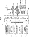
- Fig. 2 is a schematic diagram showing an electric system and a power system.
- the electric grass mowing machine includes: a vehicle body 15 that is supported by a caster wheel unit 3 including front wheels and a drive wheel unit 2 including rear wheels (drive wheels); a battery 20 that is disposed in the rear portion of the vehicle body 15; a driver's seat 11 that is disposed in front of the battery 20; a rollover protection frame 12 that is provided upright on the back side of the driver's seat 11; and a mower unit 13 that is provided in a space below the vehicle body 15 and between the caster wheel unit 3 and the drive wheel unit 2, and is suspended from the vehicle body 15 so as to be capable of moving up and down via a lifting link mechanism.
- Power is supplied to the drive wheel unit 2 and the mower unit 13 via an inverter 4 that performs operation under control of a control unit 5 (
- a floor plate is provided to function as a foot placement surface for the driver; and a brake pedal 14 protrudes upward through the floor plate.
- a left steering lever 1a and a right steering lever 1b are disposed to be pivotable about a horizontal pivot axis extending in a transverse direction of the vehicle body.
- an operation panel 18 including a switch button or a switch lever for the electric control system.
- a mower switch (not shown) for activating the mower unit 13 is disposed in the vicinity of the operation panel 18.
- the left steering lever 1a, the right steering lever 1b, the brake pedal 14 and the mower switch are operated by the driver.
- a left rear wheel 2a and a right rear wheel 2b are driven by a left wheel motor 21 and a right wheel motor 22, respectively, each to form a travel electric motor acting as a driving source.
- the left wheel motor 21 and the right wheel motor 22 are shown like in-wheel motors, but they are not necessarily in-wheel motors.
- the power from the battery 20 is independently adjusted by a left wheel electric power supply section 41 and a right wheel electric power supply section 42 that are included in the inverter 4, and then supplied to the left wheel motor 21 and the right wheel motor 22 that constitutes the travel electric motor.
- the rotational speed and/or the torque of the left wheel motor 21 and the right wheel motor 22 vary according to the power supplied from the left wheel electric power supply section 41 and the right wheel electric power supply section 42, respectively.
- the left rear wheel 2a and the right rear wheel 2b can have different rotational speeds (circumferential speeds/volocities) and thus difference in speed between the right and left rear wheels, whereby the electric grass mowing machine can change its direction of movement.
- the supply power that is outputted from the left wheel electric power supply section 41 and the right wheel electric power supply section 42 is proportional to a target rotational speed (target speed) calculated by the control unit 5, but if the actual rotational speed (actual speed) falls below the target rotational speed (target speed) due to traveling loads, the supply power is changed so as to increase the motor output torque.
- the mower unit 13 (an example of a work implement) includes three rotor blades 131a, 131b, 131c.
- the rotor blades 131a, 131b, 131c are respectively driven by mower motors 130a, 130b, 130c that constitute a work electric motor 130 acting as a driving source.
- the mower motors 130a, 130b, 130c are rotationally driven by the power supplied from a mower electric power supply section 43 included in the inverter 4.
- the left wheel motor 21, the right wheel motor 22 and the mower motors 130a, 130b, 130c are provided to constitute an electric motor unit that uses the battery 20 as a power source.
- control unit 5 is connected to a regenerative electric power detection device 6, a wheel state detection device 7, a steering state detection device 8, a battery state detection device 9 and a mower state detection device 10 that are input devices thereto; and the control unit 5 is also connected to the inverter 4 that is an output device therefrom.
- the regenerative electric power detection device 6 is configured to detect the generation of regenerative electric power in the electric motor unit.
- the regenerative electric power detection device 6 includes two regenerative electric power detection devices so as to individually detect the generation of regenerative electric power in the left wheel motor 21 and the right wheel motor 22.
- the regenerative electric power detection device 6 is configured to detect the generation of regenerative electric power by checking the flow of electric current flowing through the inverter 4.
- the wheel state detection device 7 includes sensors that detect information regarding the wheels such as a left rear wheel rotation detection sensor 70a that detects the rotational speed of the left rear wheel 2a, and a right rear wheel rotation detection sensor 70b that detects the rotational speed of the right rear wheel 2b.
- the steering state detection device 8 detects the operation state of a steering unit 1.
- the steering state detection device 8 includes various sensors that detect information regarding steering, including a left steering angle detection sensor 80a that detects the pivoting angle of the left steering lever 1a; a right steering angle detection sensor 80b that detects the pivoting angle of the right steering lever 1b; a brake detection sensor 80c that detects the operating angle of the brake pedal 14; and a mower sensor 80d that detects the operation of the mower switch.
- the battery state detection device 9 detects information regarding the charge state of the battery 20 such as the remaining capacity of the battery 20.
- the battery state detection device 9 includes a temperature sensor 90a that detects the temperature of the battery 20; a voltage sensor 90b that detects voltage; a current sensor 90c that detects electric current; and a charge rate calculation section 90d that calculates the rate of charge based on the electric current, voltage, temperature and the like of the battery 20.
- the mower state detection device 10 detects the operation state or the like of the mower unit 13.
- the mower state detection device 10 includes rotation sensors 100a, 100b, 100c that respectively detect the rotational speeds of the mower motors 130a, 130b, 130c.
- a motor control unit 50 including a travel control section 51 and a mower control section 52; a charge control section 53; and a sensor information processing section 54.
- the travel control section 51, the mower control section 52, the charge control section 53 and the sensor information processing section 54 are substantially constructed through execution of a program, but may be at least partially constructed by hardware where necessary.
- the sensor information processing section 54 processes sensor signals inputted from the regenerative electric power detection device 6, the wheel state detection device 7, the steering state detection device 8, the battery state detection device 9 and the mower state detection device 10; and converts the sensor signals into information that can be used in the control unit 5.
- the travel control section 51 functions to calculate the amount of control (for example, the amount of power supplied) with respect to the left wheel motor 21 and the right wheel motor 22 based on the amount of operation of the steering unit 1.
- the travel control section 51 determines the rotational speed (torque) of the left rear wheel 2a, and thus the rotational speed (torque) of the left wheel motor 21, based on the detection value of the left steering angle detection sensor 80a that detects the amount of operation of the left steering lever 1a performed by the driver.
- the travel control section 51 determines the rotational speed (torque) of the right rear wheel 2b, and thus the rotational speed (torque) of the right wheel motor 22, based on the detection value of the right steering angle detection sensor 80b that detects the amount of operation of the right steering lever 1b performed by the driver. Furthermore, the amount of power based on the rotational speeds (torques) is calculated. For the calculation, a table and a function that represent the relationship between the operating position and the rotational speed are used.
- the travel control section 51 transmits inverter control signals to the left wheel electric power supply section 41 and the right wheel electric power supply section 42 of the inverter 4 such that the amount of power determined is provided to the left wheel motor 21 and the right wheel motor 22. Furthermore, the travel control section 51 stops supply of power to the left/right wheel motors 21, 22 based on the detection of an operation of the brake pedal 14, and thereby regenerative braking by the left/right wheel motors 21, 22 is realized.
- the mower control section 52 controls supply of power to the mower motors 130a, 130b, 130c.
- the mower control section 52 supplies power to the mower motors 130a, 130b, 130c via the mower electric power supply section 43 in response to the mower switch (not shown) being turned on by the driver; and stops the supply of power to the mower motors 130a, 130b, 130c in response to the mower switch being turned off.
- the charge control section 53 controls charging power to the battery 20 and discharging power from the battery 20.
- the power discharged from the battery 20 is mainly supplied via the inverter 4 to the left/right wheel motors 21, 22 and the mower motors 130a, 130b, 130c.
- the battery 20 can be charged by using not only the power from a commercial power supply that is not shown in the diagram, but also the regenerative electric power generated through regenerative braking by the left/right wheel motors 21, 22.
- the charge control section 53 manages the rate of charge of the battery 20 by using four separate regions: an overdischarge (undercharge) region where the rate of charge is lowest, a charge/discharge region, a regenerative electric power margin region and an overcharge region. If the battery is not charged before the rate of charge falls in the overdischarge region, an unexpected motor stoppage or the like occurs. If, on the other hand, the rate of charge reaches the overcharge region, it causes damage to the battery 20, and it is therefore necessary to avoid charging (also called overcharging) that causes the rate of charge to reach the overcharge region. In order to reliably avoid the rate of charge reaching the overcharge region, the regenerative electric power margin region is provided between the charge/discharge region and the overcharge region.
- the motor control unit 50 is configured to supply the regenerative electric power to a motor that is not in operation among the plurality of motors, and provide a non-rotation current instruction to the inverter 4, the non-rotation current instruction being an instruction for generating a magnetic flux that does not cause the motor to rotate by using vector control.
- the motor control unit 50 uses vector control to perform drive control of the left/right wheel motors 21, 22 via the left/right wheel electric power supply sections 41, 42, as well as drive control of the mower motors 130a, 130b, 130c via the mower electric power supply section 43. Furthermore, the motor control unit 50 can generate a non-rotation current instruction for setting a q-axis current (component) to zero, and provides the generated non-rotation current instruction to the inverter 4. As a result of axis current (torque current component) flowing through the motor being set to zero, the motor torque falls to zero, and thus the motor does not rotate while consuming power. Accordingly, in order to avoid overcharge of the battery 20, it is possible to consume the regenerative electric power at a motor that is not in operation, without causing the motor to rotate.
- the generated regenerative electric power can be consumed by driving the mower motors 130a, 130b, 130c, rather than by charging the battery 20. Accordingly, when the rate of charge is in the regenerative electric power margin region, the regenerative electric power generated in the left/right wheel motors 21, 22 can be consumed by the mower motors 130a, 130b, 130c. At this time, if the mower motors 130a, 130b, 130c are performing rotation operation, the mower motors 130a, 130b, 130c are kept performing the rotation operation by using the regenerative electric power instead of the power from the battery 20.
- the mower motors 130a, 130b, 130c cannot perform rotation operation. For this reason, at the time when the regenerative electric power is supplied to the mower motors 130a, 130b, 130c, a regenerative electric power consumption instruction is outputted from the sensor information processing section 54, and a non-rotation current instruction for setting the q-axis current component of the electric current supplied to the mower motors 130a, 130b, 130c to zero is provided to the inverter 4. In this way, the regenerative electric power can be consumed by the mower motors 130a, 130b, 130c, without causing the mower motors to rotate.
- the regenerative electric power generated in the left/right wheel motors 21, 22 is consumed by the mower motors 130a, 130b, 130c. Conversely, the regenerative electric power generated in the mower motors 130a, 130b, 130c may be consumed by the left/right wheel motors 21, 22.
- the motor control unit 50 provides a regenerative electric power consumption instruction to the inverter 4, the regenerative electric power consumption instruction being an instruction for supplying the regenerative electric power to the travel electric motor (the left/right wheel motors 21, 22).
- the motor control unit 50 supplies the regenerative electric power to the travel electric motor (the left/right wheel motors 21, 22) via the inverter 4, and provides a non-rotation current instruction to the inverter 4.
- the inverter 4 (the left wheel electric power supply section 41, the right wheel electric power supply section 42 and the mower electric power supply section 43) is controlled such that the q-axis current component of the electric current supplied to the other electric motor falls to zero.
Landscapes
- Engineering & Computer Science (AREA)
- Power Engineering (AREA)
- Transportation (AREA)
- Mechanical Engineering (AREA)
- Life Sciences & Earth Sciences (AREA)
- Environmental Sciences (AREA)
- Sustainable Energy (AREA)
- Sustainable Development (AREA)
- Combustion & Propulsion (AREA)
- Chemical & Material Sciences (AREA)
- Harvester Elements (AREA)
- Control Of Multiple Motors (AREA)
- Inverter Devices (AREA)
- Charge And Discharge Circuits For Batteries Or The Like (AREA)
- Electric Propulsion And Braking For Vehicles (AREA)
Applications Claiming Priority (1)
| Application Number | Priority Date | Filing Date | Title |
|---|---|---|---|
| JP2017095337A JP7026452B2 (ja) | 2017-05-12 | 2017-05-12 | 電動作業車 |
Publications (2)
| Publication Number | Publication Date |
|---|---|
| EP3401153A1 true EP3401153A1 (de) | 2018-11-14 |
| EP3401153B1 EP3401153B1 (de) | 2022-05-04 |
Family
ID=60654736
Family Applications (1)
| Application Number | Title | Priority Date | Filing Date |
|---|---|---|---|
| EP17205991.7A Active EP3401153B1 (de) | 2017-05-12 | 2017-12-07 | Elektrisches nutzfahrzeug |
Country Status (3)
| Country | Link |
|---|---|
| US (1) | US10821854B2 (de) |
| EP (1) | EP3401153B1 (de) |
| JP (1) | JP7026452B2 (de) |
Cited By (1)
| Publication number | Priority date | Publication date | Assignee | Title |
|---|---|---|---|---|
| WO2020253821A1 (zh) * | 2019-06-21 | 2020-12-24 | 南京德朔实业有限公司 | 骑乘式割草机 |
Families Citing this family (5)
| Publication number | Priority date | Publication date | Assignee | Title |
|---|---|---|---|---|
| FR3039355B1 (fr) * | 2015-07-27 | 2017-07-14 | Pellenc Sa | Tondeuse electrique a lames multiples |
| JP7313109B2 (ja) * | 2017-04-24 | 2023-07-24 | 株式会社クボタ | 電動草刈機 |
| US11173780B2 (en) | 2018-01-04 | 2021-11-16 | Delta Systems, Inc. | Hybrid mower with electric blade control system |
| JP7193415B2 (ja) * | 2019-05-21 | 2022-12-20 | 株式会社クボタ | モーアユニット |
| JP7390998B2 (ja) * | 2020-09-16 | 2023-12-04 | 株式会社クボタ | 草刈装置 |
Citations (3)
| Publication number | Priority date | Publication date | Assignee | Title |
|---|---|---|---|---|
| JP2001128315A (ja) | 1999-10-25 | 2001-05-11 | Yamaha Motor Co Ltd | ハイブリッド駆動式移動装置 |
| US20130054070A1 (en) * | 2011-08-31 | 2013-02-28 | Kokusan Denki Co., Ltd. | Electric working vehicle |
| JP2013212006A (ja) | 2012-03-30 | 2013-10-10 | Kubota Corp | 乗用電動作業機 |
Family Cites Families (6)
| Publication number | Priority date | Publication date | Assignee | Title |
|---|---|---|---|---|
| US20120159916A1 (en) * | 2007-01-15 | 2012-06-28 | Kanzaki Kokyukoki Manufacturing Co., Ltd. | Control sysytem for motor-driven lawnmower vehicle |
| WO2010048561A2 (en) * | 2008-10-23 | 2010-04-29 | Hydro-Gear Limited Partnership | Control systems and methods for electric motors of utility vehicles |
| JP5652659B2 (ja) * | 2011-03-30 | 2015-01-14 | アイシン・エィ・ダブリュ株式会社 | 電動機制御装置 |
| JP5830449B2 (ja) * | 2012-08-30 | 2015-12-09 | 日立オートモティブシステムズ株式会社 | 電動車駆動システム |
| JP5942958B2 (ja) * | 2013-10-29 | 2016-06-29 | トヨタ自動車株式会社 | 電動車両 |
| CN107848423B (zh) * | 2015-07-29 | 2020-08-18 | 日产自动车株式会社 | 电动车辆的控制装置以及电动车辆的控制方法 |
-
2017
- 2017-05-12 JP JP2017095337A patent/JP7026452B2/ja active Active
- 2017-12-06 US US15/833,034 patent/US10821854B2/en active Active
- 2017-12-07 EP EP17205991.7A patent/EP3401153B1/de active Active
Patent Citations (3)
| Publication number | Priority date | Publication date | Assignee | Title |
|---|---|---|---|---|
| JP2001128315A (ja) | 1999-10-25 | 2001-05-11 | Yamaha Motor Co Ltd | ハイブリッド駆動式移動装置 |
| US20130054070A1 (en) * | 2011-08-31 | 2013-02-28 | Kokusan Denki Co., Ltd. | Electric working vehicle |
| JP2013212006A (ja) | 2012-03-30 | 2013-10-10 | Kubota Corp | 乗用電動作業機 |
Cited By (1)
| Publication number | Priority date | Publication date | Assignee | Title |
|---|---|---|---|---|
| WO2020253821A1 (zh) * | 2019-06-21 | 2020-12-24 | 南京德朔实业有限公司 | 骑乘式割草机 |
Also Published As
| Publication number | Publication date |
|---|---|
| JP2018191521A (ja) | 2018-12-06 |
| JP7026452B2 (ja) | 2022-02-28 |
| US10821854B2 (en) | 2020-11-03 |
| US20180326860A1 (en) | 2018-11-15 |
| EP3401153B1 (de) | 2022-05-04 |
Similar Documents
| Publication | Publication Date | Title |
|---|---|---|
| EP3401153B1 (de) | Elektrisches nutzfahrzeug | |
| US10293853B2 (en) | Vehicle having independently driven and controlled right and left drive wheels | |
| EP2110295B1 (de) | Elektrisches Bodenbearbeitungsfahrzeug | |
| US9825559B2 (en) | Motor control system and control system for electric motor-driven vehicle | |
| EP2749446B1 (de) | Regenerative Bremssteuerungsvorrichtung | |
| JP4513612B2 (ja) | 車両のトルク配分制御装置 | |
| US20180264928A1 (en) | Work Vehicle | |
| JP7266427B2 (ja) | 作業車両 | |
| JP5847632B2 (ja) | 乗用電動作業機 | |
| JP5912624B2 (ja) | ハイブリッド車両の制御装置 | |
| JP7012610B2 (ja) | 電力制御装置 | |
| JP2004350475A (ja) | 作業車両の伝動装置 | |
| US9919697B2 (en) | Work vehicle | |
| JP2013126383A (ja) | 草刈機 | |
| JP6735698B2 (ja) | 作業車 | |
| WO2023145192A1 (ja) | 電動作業車 | |
| US20230309442A1 (en) | Electric work vehicle | |
| WO2023127363A1 (ja) | 電動作業車 | |
| JP7227387B2 (ja) | 作業機 | |
| JP2023152732A (ja) | 電動作業車両 | |
| JP2023097968A (ja) | 電動作業車 | |
| US10442425B2 (en) | Work vehicle | |
| JP2014231297A (ja) | ハイブリッド作業機械 | |
| JP2023110658A (ja) | 電動作業車 |
Legal Events
| Date | Code | Title | Description |
|---|---|---|---|
| PUAI | Public reference made under article 153(3) epc to a published international application that has entered the european phase |
Free format text: ORIGINAL CODE: 0009012 |
|
| STAA | Information on the status of an ep patent application or granted ep patent |
Free format text: STATUS: THE APPLICATION HAS BEEN PUBLISHED |
|
| AK | Designated contracting states |
Kind code of ref document: A1 Designated state(s): AL AT BE BG CH CY CZ DE DK EE ES FI FR GB GR HR HU IE IS IT LI LT LU LV MC MK MT NL NO PL PT RO RS SE SI SK SM TR |
|
| AX | Request for extension of the european patent |
Extension state: BA ME |
|
| STAA | Information on the status of an ep patent application or granted ep patent |
Free format text: STATUS: REQUEST FOR EXAMINATION WAS MADE |
|
| 17P | Request for examination filed |
Effective date: 20190513 |
|
| RBV | Designated contracting states (corrected) |
Designated state(s): AL AT BE BG CH CY CZ DE DK EE ES FI FR GB GR HR HU IE IS IT LI LT LU LV MC MK MT NL NO PL PT RO RS SE SI SK SM TR |
|
| STAA | Information on the status of an ep patent application or granted ep patent |
Free format text: STATUS: EXAMINATION IS IN PROGRESS |
|
| 17Q | First examination report despatched |
Effective date: 20191001 |
|
| RIC1 | Information provided on ipc code assigned before grant |
Ipc: B60L 15/02 20060101ALI20200316BHEP Ipc: B60L 7/00 20060101AFI20200316BHEP Ipc: B60L 58/12 20190101ALI20200316BHEP Ipc: B60L 7/22 20060101ALI20200316BHEP Ipc: B60L 7/10 20060101ALI20200316BHEP |
|
| STAA | Information on the status of an ep patent application or granted ep patent |
Free format text: STATUS: EXAMINATION IS IN PROGRESS |
|
| GRAP | Despatch of communication of intention to grant a patent |
Free format text: ORIGINAL CODE: EPIDOSNIGR1 |
|
| STAA | Information on the status of an ep patent application or granted ep patent |
Free format text: STATUS: GRANT OF PATENT IS INTENDED |
|
| INTG | Intention to grant announced |
Effective date: 20210929 |
|
| GRAJ | Information related to disapproval of communication of intention to grant by the applicant or resumption of examination proceedings by the epo deleted |
Free format text: ORIGINAL CODE: EPIDOSDIGR1 |
|
| STAA | Information on the status of an ep patent application or granted ep patent |
Free format text: STATUS: EXAMINATION IS IN PROGRESS |
|
| INTC | Intention to grant announced (deleted) | ||
| GRAS | Grant fee paid |
Free format text: ORIGINAL CODE: EPIDOSNIGR3 |
|
| STAA | Information on the status of an ep patent application or granted ep patent |
Free format text: STATUS: GRANT OF PATENT IS INTENDED |
|
| GRAP | Despatch of communication of intention to grant a patent |
Free format text: ORIGINAL CODE: EPIDOSNIGR1 |
|
| GRAA | (expected) grant |
Free format text: ORIGINAL CODE: 0009210 |
|
| STAA | Information on the status of an ep patent application or granted ep patent |
Free format text: STATUS: THE PATENT HAS BEEN GRANTED |
|
| INTG | Intention to grant announced |
Effective date: 20220314 |
|
| AK | Designated contracting states |
Kind code of ref document: B1 Designated state(s): AL AT BE BG CH CY CZ DE DK EE ES FI FR GB GR HR HU IE IS IT LI LT LU LV MC MK MT NL NO PL PT RO RS SE SI SK SM TR |
|
| REG | Reference to a national code |
Ref country code: GB Ref legal event code: FG4D |
|
| REG | Reference to a national code |
Ref country code: CH Ref legal event code: EP |
|
| REG | Reference to a national code |
Ref country code: AT Ref legal event code: REF Ref document number: 1488699 Country of ref document: AT Kind code of ref document: T Effective date: 20220515 |
|
| REG | Reference to a national code |
Ref country code: DE Ref legal event code: R096 Ref document number: 602017056838 Country of ref document: DE |
|
| REG | Reference to a national code |
Ref country code: IE Ref legal event code: FG4D |
|
| REG | Reference to a national code |
Ref country code: LT Ref legal event code: MG9D |
|
| REG | Reference to a national code |
Ref country code: NL Ref legal event code: MP Effective date: 20220504 |
|
| REG | Reference to a national code |
Ref country code: AT Ref legal event code: MK05 Ref document number: 1488699 Country of ref document: AT Kind code of ref document: T Effective date: 20220504 |
|
| PG25 | Lapsed in a contracting state [announced via postgrant information from national office to epo] |
Ref country code: SE Free format text: LAPSE BECAUSE OF FAILURE TO SUBMIT A TRANSLATION OF THE DESCRIPTION OR TO PAY THE FEE WITHIN THE PRESCRIBED TIME-LIMIT Effective date: 20220504 Ref country code: PT Free format text: LAPSE BECAUSE OF FAILURE TO SUBMIT A TRANSLATION OF THE DESCRIPTION OR TO PAY THE FEE WITHIN THE PRESCRIBED TIME-LIMIT Effective date: 20220905 Ref country code: NO Free format text: LAPSE BECAUSE OF FAILURE TO SUBMIT A TRANSLATION OF THE DESCRIPTION OR TO PAY THE FEE WITHIN THE PRESCRIBED TIME-LIMIT Effective date: 20220804 Ref country code: NL Free format text: LAPSE BECAUSE OF FAILURE TO SUBMIT A TRANSLATION OF THE DESCRIPTION OR TO PAY THE FEE WITHIN THE PRESCRIBED TIME-LIMIT Effective date: 20220504 Ref country code: LT Free format text: LAPSE BECAUSE OF FAILURE TO SUBMIT A TRANSLATION OF THE DESCRIPTION OR TO PAY THE FEE WITHIN THE PRESCRIBED TIME-LIMIT Effective date: 20220504 Ref country code: HR Free format text: LAPSE BECAUSE OF FAILURE TO SUBMIT A TRANSLATION OF THE DESCRIPTION OR TO PAY THE FEE WITHIN THE PRESCRIBED TIME-LIMIT Effective date: 20220504 Ref country code: GR Free format text: LAPSE BECAUSE OF FAILURE TO SUBMIT A TRANSLATION OF THE DESCRIPTION OR TO PAY THE FEE WITHIN THE PRESCRIBED TIME-LIMIT Effective date: 20220805 Ref country code: FI Free format text: LAPSE BECAUSE OF FAILURE TO SUBMIT A TRANSLATION OF THE DESCRIPTION OR TO PAY THE FEE WITHIN THE PRESCRIBED TIME-LIMIT Effective date: 20220504 Ref country code: ES Free format text: LAPSE BECAUSE OF FAILURE TO SUBMIT A TRANSLATION OF THE DESCRIPTION OR TO PAY THE FEE WITHIN THE PRESCRIBED TIME-LIMIT Effective date: 20220504 Ref country code: BG Free format text: LAPSE BECAUSE OF FAILURE TO SUBMIT A TRANSLATION OF THE DESCRIPTION OR TO PAY THE FEE WITHIN THE PRESCRIBED TIME-LIMIT Effective date: 20220804 Ref country code: AT Free format text: LAPSE BECAUSE OF FAILURE TO SUBMIT A TRANSLATION OF THE DESCRIPTION OR TO PAY THE FEE WITHIN THE PRESCRIBED TIME-LIMIT Effective date: 20220504 |
|
| PG25 | Lapsed in a contracting state [announced via postgrant information from national office to epo] |
Ref country code: RS Free format text: LAPSE BECAUSE OF FAILURE TO SUBMIT A TRANSLATION OF THE DESCRIPTION OR TO PAY THE FEE WITHIN THE PRESCRIBED TIME-LIMIT Effective date: 20220504 Ref country code: PL Free format text: LAPSE BECAUSE OF FAILURE TO SUBMIT A TRANSLATION OF THE DESCRIPTION OR TO PAY THE FEE WITHIN THE PRESCRIBED TIME-LIMIT Effective date: 20220504 Ref country code: LV Free format text: LAPSE BECAUSE OF FAILURE TO SUBMIT A TRANSLATION OF THE DESCRIPTION OR TO PAY THE FEE WITHIN THE PRESCRIBED TIME-LIMIT Effective date: 20220504 Ref country code: IS Free format text: LAPSE BECAUSE OF FAILURE TO SUBMIT A TRANSLATION OF THE DESCRIPTION OR TO PAY THE FEE WITHIN THE PRESCRIBED TIME-LIMIT Effective date: 20220904 |
|
| PG25 | Lapsed in a contracting state [announced via postgrant information from national office to epo] |
Ref country code: SM Free format text: LAPSE BECAUSE OF FAILURE TO SUBMIT A TRANSLATION OF THE DESCRIPTION OR TO PAY THE FEE WITHIN THE PRESCRIBED TIME-LIMIT Effective date: 20220504 Ref country code: SK Free format text: LAPSE BECAUSE OF FAILURE TO SUBMIT A TRANSLATION OF THE DESCRIPTION OR TO PAY THE FEE WITHIN THE PRESCRIBED TIME-LIMIT Effective date: 20220504 Ref country code: RO Free format text: LAPSE BECAUSE OF FAILURE TO SUBMIT A TRANSLATION OF THE DESCRIPTION OR TO PAY THE FEE WITHIN THE PRESCRIBED TIME-LIMIT Effective date: 20220504 Ref country code: EE Free format text: LAPSE BECAUSE OF FAILURE TO SUBMIT A TRANSLATION OF THE DESCRIPTION OR TO PAY THE FEE WITHIN THE PRESCRIBED TIME-LIMIT Effective date: 20220504 Ref country code: DK Free format text: LAPSE BECAUSE OF FAILURE TO SUBMIT A TRANSLATION OF THE DESCRIPTION OR TO PAY THE FEE WITHIN THE PRESCRIBED TIME-LIMIT Effective date: 20220504 Ref country code: CZ Free format text: LAPSE BECAUSE OF FAILURE TO SUBMIT A TRANSLATION OF THE DESCRIPTION OR TO PAY THE FEE WITHIN THE PRESCRIBED TIME-LIMIT Effective date: 20220504 |
|
| REG | Reference to a national code |
Ref country code: DE Ref legal event code: R097 Ref document number: 602017056838 Country of ref document: DE |
|
| REG | Reference to a national code |
Ref country code: DE Ref legal event code: R082 Ref document number: 602017056838 Country of ref document: DE Representative=s name: CBDL PATENTANWAELTE GBR, DE |
|
| PLBE | No opposition filed within time limit |
Free format text: ORIGINAL CODE: 0009261 |
|
| STAA | Information on the status of an ep patent application or granted ep patent |
Free format text: STATUS: NO OPPOSITION FILED WITHIN TIME LIMIT |
|
| PG25 | Lapsed in a contracting state [announced via postgrant information from national office to epo] |
Ref country code: AL Free format text: LAPSE BECAUSE OF FAILURE TO SUBMIT A TRANSLATION OF THE DESCRIPTION OR TO PAY THE FEE WITHIN THE PRESCRIBED TIME-LIMIT Effective date: 20220504 |
|
| 26N | No opposition filed |
Effective date: 20230207 |
|
| PG25 | Lapsed in a contracting state [announced via postgrant information from national office to epo] |
Ref country code: SI Free format text: LAPSE BECAUSE OF FAILURE TO SUBMIT A TRANSLATION OF THE DESCRIPTION OR TO PAY THE FEE WITHIN THE PRESCRIBED TIME-LIMIT Effective date: 20220504 |
|
| REG | Reference to a national code |
Ref country code: CH Ref legal event code: PL |
|
| GBPC | Gb: european patent ceased through non-payment of renewal fee |
Effective date: 20221207 |
|
| REG | Reference to a national code |
Ref country code: BE Ref legal event code: MM Effective date: 20221231 |
|
| PG25 | Lapsed in a contracting state [announced via postgrant information from national office to epo] |
Ref country code: LU Free format text: LAPSE BECAUSE OF NON-PAYMENT OF DUE FEES Effective date: 20221207 |
|
| PG25 | Lapsed in a contracting state [announced via postgrant information from national office to epo] |
Ref country code: LI Free format text: LAPSE BECAUSE OF NON-PAYMENT OF DUE FEES Effective date: 20221231 Ref country code: IE Free format text: LAPSE BECAUSE OF NON-PAYMENT OF DUE FEES Effective date: 20221207 Ref country code: GB Free format text: LAPSE BECAUSE OF NON-PAYMENT OF DUE FEES Effective date: 20221207 Ref country code: CH Free format text: LAPSE BECAUSE OF NON-PAYMENT OF DUE FEES Effective date: 20221231 |
|
| PG25 | Lapsed in a contracting state [announced via postgrant information from national office to epo] |
Ref country code: BE Free format text: LAPSE BECAUSE OF NON-PAYMENT OF DUE FEES Effective date: 20221231 |
|
| PG25 | Lapsed in a contracting state [announced via postgrant information from national office to epo] |
Ref country code: IT Free format text: LAPSE BECAUSE OF FAILURE TO SUBMIT A TRANSLATION OF THE DESCRIPTION OR TO PAY THE FEE WITHIN THE PRESCRIBED TIME-LIMIT Effective date: 20220504 |
|
| PGFP | Annual fee paid to national office [announced via postgrant information from national office to epo] |
Ref country code: FR Payment date: 20231108 Year of fee payment: 7 Ref country code: DE Payment date: 20231031 Year of fee payment: 7 |
|
| PG25 | Lapsed in a contracting state [announced via postgrant information from national office to epo] |
Ref country code: HU Free format text: LAPSE BECAUSE OF FAILURE TO SUBMIT A TRANSLATION OF THE DESCRIPTION OR TO PAY THE FEE WITHIN THE PRESCRIBED TIME-LIMIT; INVALID AB INITIO Effective date: 20171207 |
|
| PG25 | Lapsed in a contracting state [announced via postgrant information from national office to epo] |
Ref country code: CY Free format text: LAPSE BECAUSE OF FAILURE TO SUBMIT A TRANSLATION OF THE DESCRIPTION OR TO PAY THE FEE WITHIN THE PRESCRIBED TIME-LIMIT Effective date: 20220504 |