EP3395473B1 - Verfahren zum giessen - Google Patents
Verfahren zum giessen Download PDFInfo
- Publication number
- EP3395473B1 EP3395473B1 EP17198230.9A EP17198230A EP3395473B1 EP 3395473 B1 EP3395473 B1 EP 3395473B1 EP 17198230 A EP17198230 A EP 17198230A EP 3395473 B1 EP3395473 B1 EP 3395473B1
- Authority
- EP
- European Patent Office
- Prior art keywords
- casting
- furnace
- pressure
- casting mold
- mold
- Prior art date
- Legal status (The legal status is an assumption and is not a legal conclusion. Google has not performed a legal analysis and makes no representation as to the accuracy of the status listed.)
- Active
Links
Images


Classifications
-
- B—PERFORMING OPERATIONS; TRANSPORTING
- B22—CASTING; POWDER METALLURGY
- B22D—CASTING OF METALS; CASTING OF OTHER SUBSTANCES BY THE SAME PROCESSES OR DEVICES
- B22D47/00—Casting plants
-
- B—PERFORMING OPERATIONS; TRANSPORTING
- B22—CASTING; POWDER METALLURGY
- B22D—CASTING OF METALS; CASTING OF OTHER SUBSTANCES BY THE SAME PROCESSES OR DEVICES
- B22D18/00—Pressure casting; Vacuum casting
- B22D18/04—Low pressure casting, i.e. making use of pressures up to a few bars to fill the mould
-
- B—PERFORMING OPERATIONS; TRANSPORTING
- B22—CASTING; POWDER METALLURGY
- B22D—CASTING OF METALS; CASTING OF OTHER SUBSTANCES BY THE SAME PROCESSES OR DEVICES
- B22D17/00—Pressure die casting or injection die casting, i.e. casting in which the metal is forced into a mould under high pressure
- B22D17/20—Accessories: Details
- B22D17/30—Accessories for supplying molten metal, e.g. in rations
-
- B—PERFORMING OPERATIONS; TRANSPORTING
- B22—CASTING; POWDER METALLURGY
- B22D—CASTING OF METALS; CASTING OF OTHER SUBSTANCES BY THE SAME PROCESSES OR DEVICES
- B22D18/00—Pressure casting; Vacuum casting
-
- B—PERFORMING OPERATIONS; TRANSPORTING
- B22—CASTING; POWDER METALLURGY
- B22D—CASTING OF METALS; CASTING OF OTHER SUBSTANCES BY THE SAME PROCESSES OR DEVICES
- B22D18/00—Pressure casting; Vacuum casting
- B22D18/06—Vacuum casting, i.e. making use of vacuum to fill the mould
-
- B—PERFORMING OPERATIONS; TRANSPORTING
- B22—CASTING; POWDER METALLURGY
- B22D—CASTING OF METALS; CASTING OF OTHER SUBSTANCES BY THE SAME PROCESSES OR DEVICES
- B22D18/00—Pressure casting; Vacuum casting
- B22D18/08—Controlling, supervising, e.g. for safety reasons
-
- B—PERFORMING OPERATIONS; TRANSPORTING
- B22—CASTING; POWDER METALLURGY
- B22D—CASTING OF METALS; CASTING OF OTHER SUBSTANCES BY THE SAME PROCESSES OR DEVICES
- B22D33/00—Equipment for handling moulds
-
- B—PERFORMING OPERATIONS; TRANSPORTING
- B62—LAND VEHICLES FOR TRAVELLING OTHERWISE THAN ON RAILS
- B62D—MOTOR VEHICLES; TRAILERS
- B62D21/00—Understructures, i.e. chassis frame on which a vehicle body may be mounted
Definitions
- the invention relates to a method for casting.
- Such systems with a casting device in particular for casting under a pressure generated by a gas phase, are used in foundry technology, in particular for the production of castings with high physical and mechanical parameters, in particular made of light metal alloys.
- a die-casting process is known in which, under the action of a pressure difference, a melt is conveyed from a furnace located in a hermetically sealed pantry through a pouring pipe into the cavity of a casting mold, the casting mold being arranged in another hermetically sealed equalizing chamber. In the compensation chamber, the casting solidifies at the temperature and pressure there. The finished casting is then removed from the casting mold and a new casting cycle can be carried out.
- the counter-pressure chill casting process known to the person skilled in the art also known as CPC (Counter Pressure Casting) casting process
- CPC Counter Pressure Casting
- pressurized gas is applied not only to the casting furnace, but also to the mold or casting mold.
- the actual casting process takes place both in the low-pressure casting process and in the counter-pressure die casting process with the aid of a riser pipe through which the melt is conveyed upwards into the die.
- the pressurization of the melt in the furnace for conveying the melt up into the mold is brought about in the counter-pressure mold casting process by a pressure difference in that the gas pressure in the mold is lowered somewhat. This creates an overpressure in the casting furnace that is sufficient for the melt to rise into the mold.
- the invention is therefore based on the object of providing a method for producing castings by casting under pressure, in particular by counter-pressure chill casting or in particular by low-pressure chill casting, in which the degree of automation and the control quality of the system and the method and thus productivity are increased can.
- the changeover times are to be shortened and labor-intensive steps are to be made easier in order to achieve an increase in productivity.
- pouring under pressure is understood to mean pouring under or at overpressure, normal pressure or underpressure, with one or more of these casting processes being advantageous depending on the application.
- These casting processes also include, for example, the tilting casting process, the floor casting process, the Side casting process or the top casting process, whereby one or more of these casting processes can also be advantageous here depending on the application.
- a system for casting under pressure in particular a counter-pressure chill casting system or in particular a low-pressure chill casting system, has at least one casting device consisting of a lower hermetically sealable chamber and an upper, preferably hermetically sealable chamber, which are separated from one another by an intermediate plate or mold mounting plate. If the hermetic sealability of the upper chamber is not important, the chamber can also virtually comprise just one frame, as can be the case in particular with a low-pressure chill casting system.
- the lower chamber has or is formed by a furnace with melt.
- a roughly horizontally divided casting mold is arranged, which consists of a lower casting mold half, which is arranged on the intermediate plate or the platen, and an upper casting mold half, which is arranged under an upper, vertically movable support structure, preferably another plate is, exists.
- the upper and / or the lower casting mold half can be formed from individual mold parts.
- the furnace with melt and the casting mold are connected to one another via at least one riser pipe, preferably mounted on the intermediate plate or the mold mounting plate.
- the upper casting mold half can be pivoted from the horizontal position into an approximately vertical position in such a way that the inner surface of the casting mold half can be treated, preferably by one person, in a work-saving and time-saving manner.
- the lower casting mold half can be pivoted from the horizontal position into an approximately vertical position, in such a way that the inner surface of the casting mold half can be treated, preferably by one person, in a way that makes work easier and saves time.
- the invention accordingly relates generally to a method of casting under pressure.
- the method according to the invention for casting under pressure can advantageously be a column casting installation.
- the system for casting under pressure is a vacuum casting system, in particular a vacuum casting system.
- the system for casting under pressure is a counter-pressure die casting system.
- the system for casting under pressure is a low-pressure chill casting system.
- the system for casting under pressure is a gravity die casting system.
- the system for casting under pressure is a tilting casting system.
- the system for casting under pressure is a head casting system.
- the system for casting under pressure is a floor casting system.
- the system for casting under pressure is a side casting system.
- the casting mold half can be pivoted about a horizontally running pivot axis which runs on that side of the casting device from which the inner surface of the casting mold half is to be treated, preferably by a person.
- the casting mold half is rotated by up to 135 °, preferably by up to 90 °; is particularly preferably pivotable by up to 85 ° from the horizontal position.
- the upper mold half can preferably be pivotable downwards.
- the lower mold half can preferably be pivotable upwards.
- Valves are provided, namely a large valve for the main filling of the pressure chamber with pressure medium and a small valve for more precise pressure adjustment within the pressure chamber.
- a precontrol for regulating each valve can be provided, which can be implemented as a characteristic map or as a mathematical model.
- the small valve is advantageously first opened to around 40 to 60%, preferably to around 45 to 55%, particularly preferably to around 50%, then the large valve is corrected by the preset flow rate using the control value from the pilot control of the small valve, and finally the pressure is precisely regulated with the small valve.
- two casting devices in particular two column casting devices or machines, are provided which are spaced apart are arranged side by side, with a manipulator for handling workpieces or tools of both casting devices being arranged between the casting devices.
- Suitable manipulators are known to the person skilled in the art.
- the arrangement according to the invention leads to an increased degree of automation and a measurable increase in productivity.
- a rail system can be provided on which at least one slide is arranged for fully automatic pick-up or removal and fully automatic delivery or transfer of a furnace, which oscillates between the at least one pouring device and a provision position located away from it, so that the slide has a furnace picks up at the readiness position and transfers it into the casting device which is not yet provided with a furnace, or that the carriage removes a furnace from the casting device and delivers it to a free point in the readiness position, in particular for reloading with melt.
- This refinement has the result that changeover times could be reduced from around 8 hours to surprisingly only 15 minutes.
- a rail system can be provided on which at least one slide for fully automatic picking up or removal and fully automatic delivery or transfer of a casting mold or casting mold half is arranged, which oscillates between the at least one casting device and a provision position located away from it, so that the slide has a Takes up the casting mold or casting mold half at the ready position and transfers it to the casting device which has not yet been provided with a casting mold or casting mold half, or that the carriage removes a casting mold or casting mold half from the casting device and transfers it to a free location in the ready position for further use, in particular for temporary storage or for exchange, give up. Changeover times are also significantly reduced here. The degree of automation is increased and the productivity of the system increased.
- the carriage can expediently be designed in such a way that several, preferably two, furnace positioning parts arranged next to one another are provided for fully automatic pick-up or removal and fully automatic delivery or transfer of the furnaces.
- a carriage with several oven positioning points several carriages, each with one oven positioning point, can be coupled to one another.
- a combination of at least one slide with several furnace positioning points and at least one slide with one furnace positioning point is also possible.
- the aim is to achieve the following: If there are several, preferably two, furnace positioning points in the slide, it is possible to save time on the way between a stand-by position and the casting device to take a furnace with melt in a furnace positioning point of the slide, and to empty another furnace from the casting device, in particular to empty it Take the furnace into a second, still free furnace positioning point of the carriage, then transfer the furnace provided with melt from the first furnace positioning point into the furnace-less casting device, in order to finally take the other, in particular empty furnace, which has already been included, with you on the way between the casting device and the ready position, thereby saving time this can be transferred to a free location in the readiness position for further use, in particular for reloading with melt.
- This refinement means that changeover times can be shortened even further.
- the slide can advantageously be designed in such a way that several, preferably two, mold positioning points arranged next to one another are provided for fully automatic picking up or removal and fully automatic delivery or transfer of the casting molds or casting mold halves.
- a carriage with several mold positioning points instead of a carriage with several mold positioning points, several carriages, each with a mold positioning point, can be coupled to one another.
- a combination of at least one slide with several mold positioning points and at least one slide with a mold positioning point is also possible.
- the aim is to achieve the following: If there are several, preferably two, mold positioning points in the slide, it is possible to save time on the way between a ready position and the casting device to take a new casting mold or casting mold half with you in an oven positioning point of the slide, and then to take an old casting mold from the casting device or Pick up the casting mold half in a second, still free mold positioning point of the slide, then transfer the new casting mold or casting mold half from the first mold positioning point into the casting device without a casting mold or casting mold half, in order to finally transfer the already used casting mold or casting mold half on the way between the casting device and the ready position to save time to take with you so that it can be transferred to a free position in the staging position for further use.
- This refinement means that retooling times can be shortened even further.
- the carriage has at least two levels, with a lower level for fully automatic pick-up or removal and fully automatic delivery or transfer of the furnace, and a lower level for fully automatic pick-up or removal and fully automatic delivery or transfer of the Mold or mold half is provided.
- both a retrofitting of the furnace and a retrofitting of the mold can be carried out in parallel.
- only one slide is advantageously required for both types of conversion.
- the plane can advantageously be displaceable in the horizontal and / or in the vertical direction.
- the rail system is sunk into the floor.
- the rail system is positioned on the floor.
- the intermediate plate or the platen has predetermined temperature control channels, preferably cooling channels, whereby these end in connections for temperature control lines arranged outside the casting device, in particular for cooling lines, which are arranged on the intermediate plate or the clamping plate, preferably in the edge area . This means that the temperature control lines do not hinder the conversion of the casting mold or the furnace.
- an additional cooling plate or a so-called cooling stone which according to the prior art was arranged between the intermediate plate or platen and the lower casting mold half or casting mold, can be dispensed with.
- the additional cooling plate had the purpose of guiding cooling media, in particular cooling water or cooling air, from the outside into the upper chamber and correspondingly to the casting mold.
- a further increase in productivity is achieved by increasing the service life of the intermediate plate or mold mounting plate provided with temperature control channels, in that the inner surfaces of the temperature control channels can be nickel-plated. This leads in particular to increased protection against corrosion.
- each temperature control line, in particular cooling line can be individually controllable, in particular time-controllable.
- the invention relates to a die-casting process, preferably a counter-pressure gravity die casting process and / or a low-pressure gravity die casting process, in particular using a system in which, under the action of a pressure difference, the melt is conveyed from a furnace in a hermetically sealed chamber through a riser pipe and the cavity a casting mold which is arranged in another, preferably hermetically sealed chamber, where the casting solidifies and whereupon it is removed from the casting mold, preferably by means of a manipulator, with the preparation for a new casting cycle following the removal of the casting upper casting mold half is pivoted from a horizontal position in such a way that the inner surface of the casting mold half is treated, preferably cleaned, smoothed and / or corrected, to make work easier and save time, preferably by one person.
- the invention generally relates to a die-casting process, in particular using a system in which, under the action of pressure, a melt is introduced into the cavity of a permanent casting mold, in which the casting solidifies and whereupon it is removed from the permanent casting mold, preferably at least with the participation of a manipulator, is removed, whereby after the removal of the casting the preparation for a new casting cycle follows in that at least one casting mold part, in particular a casting mold half, is pivoted after opening the permanent casting mold into a position in which the inner surface of this casting mold part, preferably by a person, makes work easier and treated, preferably cleaned, smoothed and / or corrected in a time-saving manner.
- the preparation for a new casting cycle follows by - in relation to other preparation steps - at the same time, before or after the lower casting mold half is pivoted from a horizontal position in such a way that the inner surface of the casting mold half, is preferably treated, preferably cleaned, smoothed and / or corrected by one person in a way that makes work easier and saves time.
- the preparation for a new casting cycle follows by - in relation to other preparation steps - at the same time, before or after the casting mold half around a horizontally running pivot axis, which runs on that side of the casting device from which is to be pivoted from the inner surface of the casting mold half, preferably by one person.
- the preparation for a new casting cycle follows by - in relation to other preparation steps - at the same time, before or after the casting mold half by up to 135 °, preferably by up to 90 °; is particularly preferably pivoted by up to 85 °.
- the pressure supply to the lower chamber or the lower pressure chamber or furnace interior and optionally the pressure supply to the upper chamber or the upper pressure chamber can expediently take place via pressure lines each with two valves connected in parallel, namely via a large valve for the main filling of the pressure chamber and via a small valve for precise pressure adjustment within the pressure chamber.
- the controls of the valves each work with a pilot control, which is implemented as a map or as a mathematical model, with the small valve first to about 40 to 60%, preferably to about 45 to 55%, particularly preferably to about 50%, to fill the pressure chambers. is opened, then the control value from the pilot control, corrected by the preset flow rate of the small valve, is applied to the large valve, and finally the pressure is precisely regulated with the small valve.
- the preparation for a new casting cycle follows by removing a furnace from the casting device at the same time, before or later by means of a slide that can be moved on a rail system, then to a Delivery position conveyed, and there at a free place a particular for reloading with melt, is delivered, and that immediately afterwards an already provided furnace provided with melt is picked up by the carriage, transported to the casting device and transferred to the casting device.
- a further development of the invention can provide that the slide has more than one, preferably two furnace positioning points, so that to change a furnace arranged in the casting device to a furnace filled with melt, the slide initially receives the furnace filled with melt in its first furnace positioning point, then moves to the casting device, there picks up one furnace in its second, still free furnace positioning point, then transfers the furnace provided with melt from the first furnace positioning point into the furnace-less casting device, in order to finally empty the one that has already been taken up
- the die-casting process is a side-casting process.
- the die casting process is a head casting process.
- the invention further relates to a method, preferably a counter-pressure chill casting process, for the production of components from the application area of chassis casting, namely wheel-guiding components, in particular links, trailing arms, wishbones, cast corners, cast nodes, frames, etc., of wheel-bearing components, in particular swivel bearings, wheel carriers, Steering knuckles, injection pump housings or the like.
- wheel-guiding components in particular links, trailing arms, wishbones, cast corners, cast nodes, frames, etc.
- wheel-bearing components in particular swivel bearings, wheel carriers, Steering knuckles, injection pump housings or the like.
- chassis parts preferably of wheel-guiding components, in particular links, trailing arms, wishbones, cast corners, cast nodes, frames or the like, or of highly stressed safety components, preferably rims, engine components, in particular
- engine blocks intake manifolds or crankcases, pressure-tight components, injection pump housings or the like.
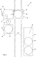
- the counter-pressure chill casting system 10 shown schematically comprises two casting devices 12 arranged at a distance from one another. Such a casting device is shown schematically in FIG Fig. 1 shown.
- the casting device 12 has a lower hermetically sealable chamber 14 and an upper hermetically sealable chamber 16, which are separated from one another by an intermediate plate or mold mounting plate 18.
- an approximately horizontally divided casting mold is arranged, which consists of a lower casting mold half 24, which is arranged on the intermediate plate or the mold mounting plate 18, and an upper casting mold half 26, which is located under an upper, vertically movable support structure 28, for example, another plate is arranged.
- This support structure 28 also has a type of hood 58 which, when the support structure 28 is moved vertically, is placed on the intermediate plate or the platen 18 to form the hermetically sealed upper chamber 16.
- Fig. 1 shows a casting device 12 in a state in which the casting mold is open and thus the hood 58 is lifted from the intermediate plate or the mold mounting plate 18.
- the furnace 20 or crucible 56 provided with melt 22 and the casting mold cavity formed by the two casting mold halves 24, 26 in the closed state are connected to one another via a riser 30 mounted on the intermediate plate or the mold mounting plate 18.
- the upper casting mold half 26 can now be pivoted from the horizontal position by, for example, approximately 85 ° downwards into an approximately vertical position, the inner surface of the casting mold half 26 becoming a die Fig. 1 viewer 32 would show.
- a person 32 who then stands in front of the casting device 12, preferably at approximately the level of the intermediate plate or the mold mounting plate 18, can then particularly easily treat the casting mold half 26, in particular clean, smooth and / or correct it.
- Fig. 1 bearing 60 and a pivot axis 36 are shown purely schematically, which are intended to illustrate the pivotability of the upper mold half 26.
- Suitable power cylinders, not shown here, are preferably provided for pivoting the upper casting mold half 26.
- a manipulator 38 for handling workpieces or tools or casting molds or casting mold halves of both casting devices 12 is arranged.
- a rail system 40 is provided, on which a slide 42 is arranged for the fully automatic pick-up or removal and the fully automatic delivery or transfer of a furnace 20.
- the carriage 42 oscillates between the casting devices 12 and a provision position 44 located at a distance therefrom.
- FIG. 2 shows how the carriage 42 stops in front of a casting device 12 in order to transfer a furnace 20 filled with melt from its furnace positioning point 62 into the casting device 12, which has not yet been provided with a furnace 20, the level 48 being moved into this casting device for this purpose. Previously, the carriage 42 picked up this furnace, leaving a free space 46 at the ready position 44.
- Fig. 3 if the slide points to the in Fig. 1 another furnace positioning point 62 shown.
- the carriage 42 first picks up the furnace filled with melt in a first furnace positioning point 62 from the ready position 44, then moves to the casting device 12 in order to pick up the empty furnace there in a second, still free furnace positioning point 62, then transfers the furnace provided with melt the first furnace positioning point 62 into the furnace-less pouring device 12 to pick up the empty furnace there in a second, still free furnace positioning point 62, then transfer the furnace provided with melt from the first furnace positioning point 62 into the furnace-less pouring device 12, in order to finally take the empty furnace that has already been taken to the ready position 44 so that it is in a free place 46 of the readiness position 44 can be transferred for refilling with melt.
- connections 52 which are preferably arranged in the edge area on the intermediate plate or the platen 18 and which are connected to the temperature control channels 52 in the intermediate plate or platen 18 and to the other side are connected to the temperature control lines 54, in particular cooling lines, arranged outside the casting device 12, these temperature control lines not standing in the way of the replacement of the casting mold or the casting mold halves 24, 26.
- an additional cooling plate or a so-called cooling stone required according to the prior art which according to the prior art is located between the intermediate plate or platen 18 and the lower casting mold half or casting mold 24 was ordered to be waived.
- the temperature control channels 50 preferably cooling channels, in the intermediate plate or mold mounting plate 18, on which the casting mold or the lower casting mold half 24 can be mounted directly, the temperature control of the casting mold 24 can be controlled much better.
- the additional cooling plate better use can be made of the upper chamber volume and the operational reliability of the casting device 12 can be improved, since fewer sealing points are incurred.
- the tightness of the cooling system is optimized overall.
Landscapes
- Engineering & Computer Science (AREA)
- Mechanical Engineering (AREA)
- Chemical & Material Sciences (AREA)
- Combustion & Propulsion (AREA)
- Transportation (AREA)
- Molds, Cores, And Manufacturing Methods Thereof (AREA)
- Fertilizers (AREA)
Description
- Die Erfindung betrifft ein Verfahren zum Gießen.
- Solche Anlagen mit einer Gießvorrichtung insbesondere zum Gießen unter einem durch eine Gasphase erzeugten Druck finden in der Gießereitechnik, insbesondere für die Herstellung von Gussstücken mit hohen physikalischen und mechanischen Kennwerten, insbesondere aus Leichtmetall-Legierungen, Anwendung.
- Aus der
DE 1178979 A ist ein Druckgießverfahren bekannt, bei dem unter der Einwirkung eines Druckunterschieds eine Schmelze aus einem in einer hermetisch abgedichteten Speisekammer befindlichen Ofen durch ein Gießrohr in den Hohlraum einer Gießform befördert wird, wobei die Gießform in einer anderen hermetisch abgedichteten Ausgleichskammer angeordnet ist. In der Ausgleichskammer erstarrt das Gussstück bei der dort vorliegenden Temperatur und bei dem dort vorliegenden Druck. Anschließend wird das fertige Gussstück aus der Gießform entnommen und ein neuer Gießzyklus kann durchgeführt werden. - Das dem Fachmann bekannte Gegendruck-Kokillengießverfahren, auch bekannt als CPC (Counter Pressure Casting)-Gießverfahren, ist eine Weiterentwicklung des so genannten Niederdruck-Gießverfahrens und aus diversen Druckschriften, beispielsweise der
EP 0 221 196 B1 , derEP 0 564 774 B1 oder derDE 34 22 121 A1 bekannt. - Im Gegensatz zum, dem Fachmann ebenfalls bekannten Niederdruck-Gießverfahren wird allerdings nicht nur der Gießofen, sondern auch die Kokille bzw. Gießform mit Druckgas beaufschlagt.
- Der eigentliche Gießvorgang erfolgt sowohl beim Niederdruck-Gießverfahren als auch beim Gegendruck-Kokillengießverfahren mit Hilfe eines Steigrohres, durch das die Schmelze nach oben in die Kokille gefördert wird.
- Die Druckbeaufschlagung der Schmelze im Ofen zum Hochfördern der Schmelze in die Kokille wird jedoch beim Gegendruck-Kokillengießverfahren durch eine Druckdifferenz herbeigeführt, indem der Gasdruck in der Kokille etwas abgesenkt wird. Dadurch entsteht ein Überdruck im Gießofen, der für das Hochsteigen der Schmelze in die Kokille ausreicht.
- Aus der
EP 1 733 823 A1 , derEP 0 398 168 A1 , derGB 1 471 882 A1 EP 0 253 692 A1 sind weitere Anlagen zum Gießen bzw. Gießverfahren bekannt. Nachteilig an den bekannten Anlagen ist, dass einige Arbeitsgänge, die nicht unmittelbar mit dem eigentlichen Gießvorgang verbunden sind, sehr arbeitsintensiv sind. Zudem sind die Umrüstzeiten, insbesondere zum Wechseln der Gießform oder zum Neubeschicken eines Ofens mit Schmelze, relativ lang. - Der Erfindung liegt daher die Aufgabe zugrunde, ein Verfahren zur Herstellung von Gussstücken durch Gießen unter Druck, insbesondere durch Gegendruck-Kokillengießen oder insbesondere durch Niederdruck-Kokillengießen bereitzustellen, bei denen der Automatisierungsgrad und die Regelungsqualität der Anlage sowie des Verfahrens und somit die Produktivität erhöht werden können. Zudem sollen die Umrüstzeiten verkürzt und arbeitsintensive Schritte erleichtert werden, um so eine Produktivitätssteigerung zu erreichen.
- Dabei wird unter dem Begriff "Gießen unter Druck" das Gießen unter bzw. bei Überdruck, Normaldruck oder Unterdruck verstanden, wobei je nach Anwendungsfall ein oder mehrere dieser Gießverfahren vorteilhaft sein können. Unter diese Gießverfahren fallen beispielsweise auch das Kippgießverfahren, das Bodengießverfahren, das Seitengießverfahren oder das Kopfgießverfahren, wobei auch hier je nach Anwendungsfall ein oder mehrere dieser Gießverfahren vorteilhaft sein können.
- Eine Anlage zum Gießen unter Druck, insbesondere eine Gegendruck-Kokillengießanlage oder insbesondere Niederdruck-Kokillengießanlage, weist wenigstens eine Gießvorrichtung aus einer unteren hermetisch abdichtbaren Kammer und einer oberen, vorzugsweise hermetisch abdichtbaren Kammer auf, die durch eine Zwischenplatte bzw. Formaufspannplatte voneinander getrennt sind. Kommt es auf die hermetische Abdichtbarkeit der oberen Kammer nicht an, kann die Kammer quasi auch nur ein Gestell umfassen, wie es insbesondere bei einer Niederdruck-Kokillengießanlage der Fall sein kann. Die untere Kammer weist einen Ofen mit Schmelze auf oder wird durch diesen gebildet. In der oberen Kammer ist eine in etwa horizontal geteilte Gießform angeordnet, die aus einer unteren Gießformhälfte, welche auf der Zwischenplatte bzw. der Formaufspannplatte angeordnet ist, und einer oberen Gießformhälfte, welche unter einer oberen, vertikal bewegbaren Tragkonstruktion, vorzugsweise einer weiteren Platte, angeordnet ist, besteht. Die obere und/oder die untere Gießformhälfte können aus einzelnen Formteilen gebildet sein. Der Ofen mit Schmelze und die Gießform sind über wenigstens ein, vorzugsweise an der Zwischenplatte bzw. der Formaufspannplatte montiertes Steigrohr miteinander verbunden.
- Weiters kann vorgesehen sein, dass die obere Gießformhälfte aus der horizontalen Position bis in eine etwa vertikale Position schwenkbar ist, derart, dass die Innenfläche der Gießformhälfte, vorzugsweise durch eine Person, arbeitserleichternd und zeitsparend behandelbar ist.
- Statt zwischen der unteren Gießformhälfte und der oberen Gießformhälfte herumzukriechen, um Reinigungsvorgänge, das Aufbringen von Schlichte oder Korrekturen an der Innenfläche der Gießformhälfte durchzuführen, kann die mit dieser Behandlung befasste Person diese Arbeiten mit einer ernormen Zeitersparnis durchführen, indem die Person diese Arbeiten vor der Gießvorrichtung stehend ausführt. Dies führt zu einer signifikanten Produktivitätssteigerung.
- Gleiches gilt, wenn die untere Gießformhälfte aus der horizontalen Position in eine etwa vertikale Position verschwenkbar ist, derart, dass die Innenfläche der Gießformhälfte, vorzugsweise durch eine Person, arbeitserleichternd und zeitsparend behandelbar ist.
- Die Erfindung betrifft entsprechend allgemein ein Verfahren zum Gießen unter Druck.
- Bei der erfindungsgemäßen Verfahren zum Gießen unter Druck kann es sich vorteilhaft um eine Säulengießanlage handeln.
- Für bestimmte Anwendungsfälle kann es von Vorteil sein, wenn es sich bei der Anlage zum Gießen unter Druck um eine Unterdruckgießanlage, insbesondere eine Vakuumgießanlage handelt.
- Für gewisse Anwendungsfälle kann es von Vorteil sein, wenn die Anlage zum Gießen unter Druck eine Gegendruck-Kokillengießanlage ist.
- Für andere Anwendungsfälle kann es von Vorteil sein, wenn die Anlage zum Gießen unter Druck eine Niederdruck-Kokillengießanlage.
- Für einige Anwendungsfälle kann es von Vorteil sein, wenn die Anlage zum Gießen unter Druck eine Schwerkraft-Kokillengießanlage ist.
- Für wieder andere Anwendungsfälle kann es von Vorteil sein, wenn die Anlage zum Gießen unter Druck eine Kippgießanlage ist.
- Für manche Anwendungsfälle kann es von Vorteil sein, wenn die Anlage zum Gießen unter Druck eine Kopfgießanlage ist.
- Für bestimmte Anwendungsfälle kann es von Vorteil sein, wenn die Anlage zum Gießen unter Druck eine Bodengießanlage ist.
- Für viele Anwendungsfälle kann es von Vorteil sein, wenn die Anlage zum Gießen unter Druck eine Seitengießanlage ist.
- Es kann zweckmäßig sein, wenn die Gießformhälfte um eine horizontal verlaufende Schwenkachse, welche auf derjenigen Seite der Gießvorrichtung verläuft, von der aus die Innenfläche der Gießformhälfte, vorzugsweise durch eine Person, behandelt werden soll, schwenkbar ist.
- Als besonders vorteilhaft kann es sein, wenn die Gießformhälfte um bis zu 135°, vorzugsweise um bis zu 90°; besonders bevorzugt um bis zu 85°, aus der horizontalen Position schwenkbar ist.
- Vorzugsweise kann die obere Gießformhälfte nach unten schwenkbar sein. Vorzugsweise kann die untere Gießformhälfte nach oben schwenkbar sein.
- Für die Druckversorgung der unteren Kammer bzw. des unteren Druckraums bzw. Ofeninnenraums und gegebenenfalls (beispielsweise im Falle einer Gegendruck-Kokillengießanlage) für die Druckversorgung der oberen Kammer bzw. des oberen Druckraums über entsprechende Druckleitungen kann es von Vorteil sein, wenn jeweils zwei parallel geschaltete Ventile vorgesehen sind, nämlich ein großes Ventil zur Hauptfüllung des Druckraums mit Druckmedium und ein kleines Ventil zur präziseren Druckeinstellung innerhalb der Druckraums.
- Zweckmäßigerweise kann jeweils eine Vorsteuerung zur Regelung jedes Ventils vorgesehen sein, welche als Kennfeld oder als mathematisches Modell realisierbar ist.
- Zur Füllung der Druckräume wird vorteilhaft zuerst das kleine Ventil auf etwa 40 bis 60 %, vorzugsweise auf etwa 45 bis 55%, besonders bevorzugt auf etwa 50% geöffnet, dann wird das große Ventil mit dem Stellwert aus der Vorsteuerung, korrigiert um den voreingestellten Durchfluss des kleinen Ventils, beaufschlagt, und schließlich wird mit dem kleinen Ventil der Druck präzise geregelt.
- Durch eine derart ausgebildete Druckversorgung kann eine höhere Produktivität erreicht und die Regelungsqualität deutlich verbessert werden.
- Es kann weiterhin vorteilhaft sein, wenn zwei Gießvorrichtungen, insbesondere zwei Säulengießvonichtungen bzw. -maschinen, vorgesehen sind, welche mit Abstand nebeneinander angeordnet sind, wobei zwischen den Gießvorrichtungen ein Manipulator zur Handhabung von Werkstücken oder Werkzeugen beider Gießvorrichtungen angeordnet ist. Geeignete Manipulatoren sind dem Fachmann bekannt. Die erfindungsgemäße Anordnung führt zu einem erhöhten Automatisierungsgrad und zu einer messbaren Produktivitätssteigerung.
- Zur Produktivitätssteigerung kann ein Schienensystem vorgesehen sein, auf dem wenigstens ein Schlitten zur vollautomatischen Aufnahme bzw. Entnahme und vollautomatischen Abgabe bzw. Überführung eines Ofens angeordnet ist, der zwischen der wenigstens einen Gießvorrichtung und einer entfernt davon liegenden Bereitstellungsposition pendelt, derart dass der Schlitten einen Ofen an der Bereitstellungsposition aufnimmt und diesen in die, noch nicht mit einem Ofen versehene Gießvonichtung überführt, oder dass der Schlitten einen Ofen aus der Gießvorrichtung entnimmt und diesen an eine freie Stelle der Bereitstellungsposition, insbesondere zur Neubeschickung mit Schmelze, abgibt. Diese Ausgestaltung führt dazu, dass Umrüstzeiten von etwa 8 Stunden auf überraschend nur 15 Minuten verkürzt werden konnten.
- Zweckmäßigerweise kann ein Schienensystem vorgesehen sein, auf dem wenigstens ein Schlitten zur vollautomatischen Aufnahme bzw. Entnahme und vollautomatischen Abgabe bzw. Überführung einer Gießform oder Gießformhälfte angeordnet ist, der zwischen der wenigstens einen Gießvorrichtung und einer entfernt davon liegenden Bereitstellungsposition pendelt, derart dass der Schlitten eine Gießform oder Gießformhälfte an der Bereitstellungsposition aufnimmt und diese in die, noch nicht mit einer Gießform oder Gießformhälfte versehene Gießvorrichtung überführt, oder dass der Schlitten eine Gießform oder Gießformhälfte aus der Gießvorrichtung entnimmt und diese an eine freie Stelle der Bereitstellungsposition zur weiteren Verwendung, insbesondere zur Zwischenlagerung oder zum Austausch, abgibt. Auch hier werden Umrüstzeiten wesentlich verkürzt. Der Automatisierungsgrad wird erhöht und die Produktivität der Anlage gesteigert.
- Zweckmäßigerweise kann der Schlitten so ausgebildet sein, dass mehrere, vorzugsweise zwei nebeneinander angeordnete Ofenpositioniersteilen zur vollautomatischen Aufnahme bzw. Entnahme und vollautomatischen Abgabe bzw. Überführung der Öfen vorgesehen sind. Anstelle eines Schlittens mit mehreren Ofenpositionierstellen können auch mehrere Schlitten mit jeweils einer Ofenpositionierstelle aneinandergekoppelt sein. Eine Kombination aus wenigstens einem Schlitten mit mehreren Ofenpositionierstellen und wenigstens einem Schlitten mit einer Ofenpositionierstelle ist auch möglich. Erreicht werden soll Folgendes: Bei Vorhandensein von mehreren, vorzugsweise von zwei Ofenpositionierstellen im Schlitten besteht die Möglichkeit, zeitsparend auf dem Weg zwischen einer Bereitstellungsposition und der Gießvorrichtung einen mit Schmelze versehenen Ofen in einer Ofenpositionierstelle des Schlittens mitzunehmen, aus der Gießvorrichtung einen anderen, insbesondere leeren Ofen in eine zweite, noch freie Ofenpositionierstelle des Schlittens aufzunehmen, anschließend den mit Schmelze versehenen Ofen aus der ersten Ofenpositionierstelle In die ofenlose Gießvorrichtung zu überführen, um schließlich den bereits aufgenommenen anderen, insbesondere leeren Ofen zeitsparend auf dem Weg zwischen Gießvorrichtung und Bereitstellungsposition mitzunehmen, damit dieser in eine freie Stelle der Bereitstellungsposition zur weiteren Verwendung, insbesondere zur Neubeschickung mit Schmelze überführt werden kann. Diese Ausgestaltung führt dazu, dass Umrüstzeiten noch weiter verkürzt werden können.
- Vorteilhaft kann der Schlitten so ausgebildet sein, dass mehrere, vorzugsweise zwei nebeneinander angeordnete Formpositionierstellen zur vollautomatischen Aufnahme bzw. Entnahme und vollautomatischen Abgabe bzw. Überführung der Gießformen oder Gießformhälften vorgesehen sind. Anstelle eines Schlittens mit mehreren Formpositionierstellen können auch mehrere Schlitten mit jeweils einer Formpositionierstelle aneinandergekoppelt sein. Eine Kombination aus wenigstens einem Schlitten mit mehreren Formpositionierstellen und wenigstens einem Schlitten mit einer Formpositionierstelle ist auch möglich. Erreicht werden soll Folgendes: Bei Vorhandensein von mehreren, vorzugsweise von zwei Formpositionierstellen im Schlitten besteht die Möglichkeit, zeitsparend auf dem Weg zwischen einer Bereitstellungsposition und der Gießvorrichtung eine neue Gießform oder Gießformhälfte in einer Ofenpositionierstelle des Schlittens mitzunehmen, aus der Gießvorrichtung dann eine ausgediente Gießform oder Gießformhälfte in eine zweite, noch freie Formpositionierstelle des Schlittens aufzunehmen, anschließend die neue Gießform oder Gießformhälfte aus der ersten Formpositionierstelle in die ohne Gießform oder Gießformhälfte versehene Gießvorrichtung zu überführen, um schließlich die bereits aufgenommene ausgediente Gießform oder Gießformhälfte zeitsparend auf dem Weg zwischen Gießvorrichtung und Bereitstellungsposition mitzunehmen, damit diese in eine freie Stelle der Bereitstellungsposition zur weiteren Verwendung überführt werden kann. Diese Ausgestaltung führt dazu, dass Umrüstzeiten noch weiter verkürzt werden können.
- Es kann von Vorteil sein, wenn der Schlitten wenigstens zwei Ebenen aufweist, wobei eine untere Ebene zur vollautomatischen Aufnahme bzw. Entnahme und vollautomatischen Abgabe bzw. Überführung des Ofens, und eine untere Ebene zur vollautomatischen Aufnahme bzw. Entnahme und vollautomatischen Abgabe bzw. Überführung der Gießform oder Gießformhätfte vorgesehen ist. Dadurch kann sowohl ein Umrüsten des Ofens als auch ein Umrüsten der Gießform parallel durchgeführt werden. Zudem ist für beide Umrüstarten vorteilhaft nur ein Schlitten erforderlich.
- Vorteilhaft kann die Ebene in horizontaler und/oder in vertikaler Richtung verfahrbar sein.
- Für bestimmte Anwendungsfälle kann es von Vorteil sein, wenn dass Schienensystem im Boden versenkt ist. Für bestimmte andere Anwendungsfälle kann es aber auch von Vorteil sein, wenn das Schienensystem auf dem Boden positioniert ist.
- Es kann vorteilhaft sein, wenn die Zwischenplatte bzw. die Formaufspannplatte vorgegebene Temperierkanäle, vorzugsweise Kühlkanäle, aufweist, wobei diese in, auf der Zwischenplatte bzw. der Aufspannplatte, vorzugsweise im Randbereich, angeordnete Anschlüsse für außerhalb der Gießvorrichtung angeordnete Temperierleitungen, insbesondere für Kühlleitungen, enden. Damit behindern die Temperierleitungen nicht das Umrüsten der Gießform oder des Ofens.
- Zudem kann so gegenüber dem Stand der Technik auf eine zusätzliche Kühlplatte bzw. einen so genannten Kühlstein, welche gemäß Stand der Technik zwischen Zwischenplatte bzw. Formaufspannplatte und der unteren Gießformhälfte bzw. Gießform angeordnet war, verzichtet werden. Die zusätzliche Kühlplatte hatte gemäß Stand der Technik den Zweck, kühlende Medien, insbesondere Kühlwasser oder Kühlluft, von außen in die obere Kammer und entsprechend zur Gießform zu führen. Durch Verlegung der Temperierkanäle, vorzugsweise Kühlkanäle, in die Zwischenplatte bzw. Formaufspannplatte, auf der die Gießform oder die untere Gießformhälfte direkt montiert ist, kann die Temperierung der Gießform besser gesteuert werden. Gleichzeitig kann durch Wegfall der zusätzlichen Kühlplatte das Kammervolumen besser ausgenutzt werden und die Betriebssicherheit der Gießvorrichtung verbessert werden, da weniger Dichtstellen anfallen. Die Dichtheit des Kühlsystems wird so optimiert.
- Eine weitere Produktivitätssteigerung wird durch eine Erhöhung der Lebensdauer der mit Temperierkanälen versehenen Zwischenplatte bzw. Formaufspannplatte erreicht, indem die Innenflächen der Temperierkanäle vernickelt sein können. Dies führt insbesondere zu einem erhöhten Korrosionsschutz.
- Es kann zweckmäßig sein, wenn jede Temperierleitung, insbesondere Kühlleitung, individuell steuerbar, insbesondere zeitsteuerbar, ist.
- Die Erfindung betrifft ein Druckgießverfahren, vorzugsweise ein Gegendruck-Kokillengießverfahren und/oder ein Niederdruck-Kokillengießverfahren, insbesondere unter Verwendung einer Anlage bei dem unter der Einwirkung eines Druckunterschieds die Schmelze aus einem in einer hermetisch abgedichteten Kammer befindlichen Ofen durch ein Steigrohr befördert wird und den Hohlraum einer Gießform ausfüllt, die in einer anderen vorzugsweise hermetisch abgedichteten Kammer angeordnet ist, wo das Gussstück erstarrt und worauf es aus der Gießform, vorzugsweise mittels eines Manipulators, entnommen wird, wobei nach der Entnahme des Gussstücks die Vorbereitung für einen neuen Gießzyklus folgt, indem die obere Gießformhälfte aus einer horizontalen Position derart verschwenkt wird, dass die Innenfläche der Gießformhälfte, vorzugsweise durch eine Person, arbeitserleichternd und zeitsparend behandelt, vorzugsweise gereinigt, geschlichtet und/oder korrigiert, wird.
- Die Erfindung betrifft entsprechend allgemein ein Druckgießverfahren, insbesondere unter Verwendung einer Anlage, bei dem unter der Einwirkung eines Druckes eine Schmelze in den Hohlraum einer Dauergießform eingebracht wird, in welcher das Gussstück erstarrt und worauf es aus der Dauergießform, vorzugsweise zumindest unter Beteiligung eines Manipulators, entnommen wird, wobei nach der Entnahme des Gussstücks die Vorbereitung für einen neuen Gießzyklus folgt, indem wenigstens ein Gießformteil, insbesondere eine Gießformhälfte, nach dem Öffnen der Dauergießform in eine Position geschwenkt wird, in welcher die Innenfläche dieses Gießformteils, vorzugsweise durch eine Person, arbeitserleichternd und zeitsparend behandelt, vorzugsweise gereinigt, geschlichtet und/oder korrigiert, wird.
- Es kann vorteilhaft sein, wenn nach der Entnahme des Gussstücks die Vorbereitung für einen neuen Gießzyklus folgt, indem - bezogen auf andere Vorbereitungsschritte - zur gleichen Zeit, vorher oder später die untere Gießformhälfte aus einer horizontalen Position derart verschwenkt wird, dass die Innenfläche der Gießformhälfte, vorzugsweise durch eine Person, arbeitserleichternd und zeitsparend behandelt, vorzugsweise gereinigt, geschlichtet und/oder korrigiert, wird.
- Es kann zweckmäßig sein, wenn nach der Entnahme des Gussstücks die Vorbereitung für einen neuen Gießzyklus folgt, indem - bezogen auf andere Vorbereitungsschritte - zur gleichen Zeit, vorher oder später die Gießformhälfte um eine horizontal verlaufende Schwenkachse, welche auf derjenigen Seite der Gießvorrichtung verläuft, von der aus die Innenfläche der Gießformhälfte, vorzugsweise durch eine Person, behandelt werden soll, verschwenkt wird.
- Es kann vorteilhaft sein, wenn nach der Entnahme des Gussstücks die Vorbereitung für einen neuen Gießzyklus folgt, indem - bezogen auf andere Vorbereitungsschritte - zur gleichen Zeit, vorher oder später die Gießformhälfte die Gießformhälfte um bis zu 135°, vorzugsweise um bis zu 90°; besonders bevorzugt um bis zu 85°, verschwenkt wird.
- Es kann von Vorteil sein, wenn nach der Entnahme des Gussstücks die Vorbereitung für einen neuen Gießzyklus folgt, indem - bezogen auf andere Vorbereitungsschritte - zur gleichen Zeit, vorher oder später die obere Gießformhälfte nach unten verschwenkt wird und/oder die untere Gießfonnhätfte nach oben verschwenkt wird.
- Zweckmäßigerweise kann die Druckversorgung der unteren Kammer bzw. des unteren Druckraums bzw. Ofeninnenraums und gegebenenfalls die Druckversorgung der oberen Kammer bzw. des oberen Druckraums über Druckleitungen mit jeweils zwei parallel geschalteten Ventilen erfolgen, nämlich über ein großes Ventil zur Hauptfüllung des Druckraumes und über ein kleines Ventil zur präzisen Druckeinstellung innerhalb der Druckraums. Die Regelungen der Ventile arbeiten jeweils mit einer Vorsteuerung, die als Kennfeld oder als mathematisches Modell realisiert wird, wobei zur Füllung der Druckräume zuerst das kleine Ventil auf etwa 40 bis 60 %, vorzugsweise auf etwa 45 bis 55%, besonders bevorzugt auf etwa 50% geöffnet wird, dann das große Ventil mit dem Stellwert aus der Vorsteuerung, korrigiert um den voreingestellten Durchfluss des kleinen Ventils, beaufschlagt wird, und schließlich mit dem kleinen Ventil der Druck präzise geregelt wird.
- Durch eine derart gesteuerte Druckversorgung kann eine höhere Produktivität erreicht und die Regelungsqualität deutlich verbessert werden.
- Es kann vorteilhaft sein, wenn nach der Entnahme des Gussstücks die Vorbereitung für einen neuen Gießzyklus folgt, indem - bezogen auf andere Vorbereitungsschritte - zur gleichen Zeit, vorher oder später mittels eines auf einem Schienensystem verfahrbaren Schlittens ein Ofen aus der Gießvorrichtung entnommen, dann zu einer Bereitstellungsposition befördert, und dort an einer freien Stelle einer insbesondere zur Neubeschickung mit Schmelze, abgegeben wird, und dass direkt anschließend ein bereits bereitgestellter, mit Schmelze versehener Ofen von dem Schlitten aufgenommen, zur Gießvorrichtung befördert und in die Gießvorrichtung überführt wird.
- Eine Weiterbildung der Erfindung kann vorsehen, dass der Schlitten mehr als eine, vorzugsweise zwei Ofenpositionierstellen aufweist, so dass zum Wechsel eines in der Gießvorrichtung angeordneten Ofens gegen ein mit Schmelze gefüllten Ofen, der Schlitten zunächst den mit Schmelze gefüllten Ofen in seiner ersten Ofenpositionierstelle aufnimmt, anschließend zur Gießvorrichtung fährt, dort den einen Ofen in seine zweite, noch freie Ofenpositionierstelle aufnimmt, anschließend den mit Schmelze versehenen Ofen aus der ersten Ofenpositionierstelle in die ofenlose Gießvorrichtung überführt, um schließlich den bereits aufgenommenen leeren Für einige Einsatzfälle kann es von Vorteil sein, wenn das Druckgießverfahren ein Seitengießverfahren ist.
- Für gewisse Einsatzfälle kann es von Vorteil sein, wenn das Druckgießverfahren ein Kopfgießverfahren ist.
- Die Erfindung betrifft weiterhin ein Verfahren vorzugsweise eines Gegendruck-Kokillengießverfahrens, zur Herstellung von Bauteilen aus dem Anwendungsbereich Fahrwerksguss, namentlich von radführenden Bauteilen, insbesondere Lenkern, Längslenkern, Querlenkern, Gussecken, Gussknoten, Rahmen usw., von radtragenden Bauteilen, insbesondere Schwenklagern, Radträgern, Achsschenkeln, von Einspritzpumpengehäusen oder dergleichen.
- Es kann vorteilhaft sein, ein Verfahren nach Anspruch 1 zur Herstellung von hoch belasteten Sicherheitsbauteilen, vorzugsweise von Felgen, von Motorkomponenten, insbesondere von Motorblöcken, Saugkrümmern oder Kurbelgehäusen, von druckdichten Bauteilen, von Einspritzpumpengehäusen oder dergleichen zu verwenden.
- Es kann auch zweckmäßig sein, ein Niederdruck-Kokillengießverfahren zur Herstellung von Fahrwerksteilen, vorzugsweise von radführenden Bauteilen, insbesondere Lenkern, Längslenkern, Querlenkern, Gussecken, Gussknoten, Rahmen oder dergleichen, oder von hoch belasteten Sicherheitsbauteilen, vorzugsweise von Felgen, von Motorkomponenten, insbesondere von Motorblöcken, Saugkrümmern oder Kurbelgehäusen, von druckdichten Bauteilen, von Einspritzpumpengehäusen oder dergleichen zu verwenden.
- Weitere Einzelheiten der Erfindung ergeben sich aus der nachfolgenden Beschreibung in Verbindung mit der Zeichnung. In dieser zeigen:
- Fig. 1
- schematisch in Seitenansicht eine erfindungsgemäße Gießvorrichtung,
- Fig. 2
- schematisch in Draufsicht eine erfindungsgemäße Anlage mit und
- Fig. 3
- schematische in Draufsicht eine zweite erfindungsgemäße Anlage.
- Werden in den
Fig. 1 bis 3 gleiche Bezugsziffern verwendet, so bezeichnen diese gleiche Teile bzw. Bereiche. - Die in
Fig. 2 schematisch dargestellte Gegendruck-Kokillengießanlage 10 umfasst zwei mit Abstand nebeneinander angeordnete Gießvorrichtungen 12. Eine solche Gießvorrichtung ist schematisch inFig. 1 dargestellt. - Die Gießvorrichtung 12 weist eine untere hermetisch abdichtbare Kammer 14 und eine obere hermetisch abdichtbare Kammer 16 auf, welche durch eine Zwischenplatte bzw. Formaufspannplatte 18 voneinander getrennt sind.
- In der unteren Kammer 14 ist ein Ofen 20 vorgesehen, der einen Tiegel 56 mit Schmelze 22 aufweist.
- In der oberen Kammer 16 ist eine in etwa horizontal geteilte Gießform angeordnet, wobei diese aus einer unteren Gießformhälfte 24, welche auf der Zwischenplatte bzw. der Formaufspannplatte 18 angeordnet ist, und einer oberen Gießformhälfte 26, welche unter einer oberen, vertikal bewegbaren Tragkonstruktion 28, beispielsweise einer weiteren Platte, angeordnet ist, besteht. Diese Tragkonstruktion 28 weist zudem eine Art Haube 58 auf, welche beim vertikalen Verfahren der Tragkonstruktion 28 nach unten auf die Zwischenplatte bzw. die Formaufspannplatte 18 zur Ausbildung der hermetisch abgedichteten oberen Kammer 16 aufsetzt.
-
Fig. 1 zeigt eine Gießvorrichtung 12 in einem Zustand, in dem die Gießform geöffnet und somit die Haube 58 von der Zwischenplatte bzw. der Formaufspannplatte 18 abgehoben ist. - Der mit Schmelze 22 versehene Ofen 20 bzw. Tiegel 56 und der durch die beiden Gießformhälften 24, 26 im geschlossenen Zustand ausgebildete Gießformhohlraum sind über ein, an der Zwischenplatte bzw. der Formaufspannplatte 18 montiertes Steigrohr 30 miteinander verbunden.
- Die obere Gießformhälfte 26 ist nun aus der horizontalen Position um beispielsweise etwa 85° nach unten in eine etwa vertikale Position schwenkbar, wobei die Innenfläche der Gießformhälfte 26 zu einer die
Fig. 1 betrachtenden Person 32 zeigen würde. Eine Person 32, die dann vor der Gießvorrichtung 12, vorzugsweise in etwa der Höhe der Zwischenplatte bzw. der Formaufspannplatte 18 steht, kann dann besonders einfach die Gießformhälfte 26 behandeln, insbesondere reinigen, schlichten und/oder korrigieren. - In
Fig. 1 sind rein schematisch Lager 60 und eine Schwenkachse 36 dargestellt, welche die Verschwenkbarkeit der oberen Gießformhälfte 26 verdeutlichen sollen. Vorzugsweise sind zum Verschwenken der oberen Gießformhälfte 26 geeignete hier nicht dargestellte Kraftzylinder vorgesehen. - Zwischen den in
Fig. 2 mit Abstand nebeneinander angeordneten zwei Gießvorrichtungen 12 ist ein Manipulator 38 zur Handhabung von Werkstücken oder Werkzeugen bzw. Gießformen oder Gießformhälften beider Gießvorrichtungen 12 angeordnet. - Auf der hinteren Seite der beiden Gießvorrichtungen 12 ist ein Schienensystem 40 vorgesehen, auf dem ein Schlitten 42 zur vollautomatischen Aufnahme bzw. Entnahme und vollautomatischen Abgabe bzw. Überführung eines Ofens 20 angeordnet ist.
- Der Schlitten 42 pendelt hierbei zwischen den Gießvorrichtungen 12 und einer entfernt davon liegenden Bereitstellungsposition 44.
- In den
Fig. 2 ist dargestellt, wie der Schlitten 42 vor einer Gießvorrichtung 12 hält, um einen mit Schmelze befüllten Ofen 20 aus seiner Ofenpositionierstelle 62 in die, noch nicht mit einem Ofen 20 versehene Gießvorrichtung 12 zu überführen, wobei hierzu die Ebene 48 in diese Gießvorrichtung verfahren wird. Zuvor hat der Schlitten 42 diesen Ofen unter Hinterlassen einer freien Stelle 46 an der Bereitstellungsposition 44 aufgenommen. - In
Fig. 3 weist der Schlitten gegenüber dem inFig. 1 dargestellten eine weitere Ofenpositionierstelle 62 auf. Dadurch ist ein zeitsparender Wechsel eines leeren in der Gießvorrichtung angeordneten Ofens gegen ein mit Schmelze gefüllten Ofen möglich. Der Schlitten 42 nimmt zunächst den mit Schmelze gefüllten Ofen in einer ersten Ofenpositionierstelle 62 aus der Bereitstellungsposition 44 auf, fährt anschließend zur Gießvorrichtung 12, um dort den leeren Ofen in eine zweite, noch freie Ofenpositionierstelle 62 aufzunehmen, überführt anschließend den mit Schmelze versehenen Ofen aus der ersten Ofenpositionierstelle 62 in die ofenlose Gießvorrichtung 12, um dort den leeren Ofen in eine zweite, noch freie Ofenpositionierstelle 62 aufzunehmen, überführt anschließend den mit Schmelze versehenen Ofen aus der ersten Ofenpositionierstelle 62 in die ofenlose Gießvorrichtung 12, um schließlich den bereits aufgenommenen leeren Ofen zur Bereitstellungsposition 44 mitzunehmen, damit dieser in eine freie Stelle 46 der Bereitstellungsposition 44 zur Neubeschickung mit Schmelze überführt werden kann. - Nicht nur eine Erleichterung für die Umrüstung der Gießvorrichtung 12 stellen auch die auf der Zwischenpfatte bzw. der Formaufspannplatte 18 vorzugsweise im Randbereich angeordneten Anschlüsse 52 dar, die auf der einen Seite mit den in der Zwischenplatte bzw. der Formaufspannplatte 18 vorgesehenen Temperierkanälen 52 und auf den anderen Seite mit den außerhalb der Gießvorrichtung 12 angeordnete Temperierteitungen 54, insbesondere Kühlleitungen, verbunden sind, wobei dem Austausch der Gießform bzw. der Gießformhälften 24, 26 diese Temperierteitungen nicht im Wege stehen.
- Vielmehr kann durch die in der Zwischenplatte bzw. der Formaufspannplatte 18 angeordneten Temperierkanäle 50 auf eine gemäß dem Stand der Technik erforderliche zusätzliche Kühlplatte bzw. einen so genannten Kühlstein, welche gemäß Stand der Technik zwischen Zwischenplatte bzw. Formaufspannplatte 18 und der unteren Gießformhälfte bzw. Gießform 24 angeordnet war, verzichtet werden. Durch Verlegung der Temperierkanäle 50, vorzugsweise Kühlkanäle, in die Zwischenplatte bzw. Formaufspannplatte 18, auf der die Gießform oder die untere Gießformhälfte 24 direkt montierbar ist, kann die Temperierung der Gießform 24 wesentlich besser gesteuert werden. Gleichzeitig kann durch Wegfall der zusätzlichen Kühlplatte das obere Kammervolumen besser ausgenutzt werden und die Betriebssicherheit der Gießvorrichtung 12 verbessert werden, da weniger Dichtstellen anfallen. Die Dichtheit des Kühlsystems wird insgesamt optimiert.
-
- 10
- Anlage
- 12
- Gießvorrichtung
- 14
- Kammer
- 16
- Kammer
- 18
- Zwischenplatte bzw. Formaufspannplatte
- 20
- Ofen
- 22
- Schmelze
- 24
- untere Gießformhälfte
- 26
- obere Gießformhälfte
- 28
- Tragkonstruktion
- 30
- Steigrohr
- 32
- Person
- 34
- Seite
- 36
- Schwenkachse
- 38
- Manipulator
- 40
- Schienensystem
- 42
- Schlitten
- 44
- Bereitstellungsposition
- 46
- freie Stelle
- 48
- untere Ebene
- 50
- Temperierkanäle
- 52
- Anschlussstelle
- 54
- Temperierleitungen
- 56
- Tiegel
- 58
- Haube
- 60
- Lager
- 62
- Ofenpositionierstelle
Claims (1)
- Druckgießverfahren, bei dem unter der Einwirkung eines Druckunterschieds eine Schmelze aus einem in einer hermetisch abgedichteten unteren Kammer bzw. eines unteren Druckraums bzw. eines Ofeninnenraums befindlichen Ofen durch ein Steigrohr befördert wird und den Hohlraum einer Gießform ausfüllt wo das Gussstück erstarrt und worauf es aus der Gießform entnommen wird, dadurch gekennzeichnet, dass die Druckversorgung der unteren Kammer bzw. des unteren Druckraums bzw. Ofeninnenraums über zwei parallel geschaltete Ventile erfolgt, nämlich über ein erstes Ventil zur Hauptfüllung des Druckraumes und über ein zweites Ventil zur präzisen Druckeinstellung innerhalb des Druckraums, wobei das erste Ventil größer ist als das zweite Ventil.
Applications Claiming Priority (4)
| Application Number | Priority Date | Filing Date | Title |
|---|---|---|---|
| DE102009032148 | 2009-07-07 | ||
| DE102010026293 | 2010-07-06 | ||
| PCT/DE2010/000780 WO2011003396A1 (de) | 2009-07-07 | 2010-07-07 | Anlage und verfahren zum giessen |
| EP10747149.2A EP2451598B1 (de) | 2009-07-07 | 2010-07-07 | Anlage zum giessen unter druck |
Related Parent Applications (2)
| Application Number | Title | Priority Date | Filing Date |
|---|---|---|---|
| EP10747149.2A Division EP2451598B1 (de) | 2009-07-07 | 2010-07-07 | Anlage zum giessen unter druck |
| EP10747149.2A Division-Into EP2451598B1 (de) | 2009-07-07 | 2010-07-07 | Anlage zum giessen unter druck |
Publications (2)
| Publication Number | Publication Date |
|---|---|
| EP3395473A1 EP3395473A1 (de) | 2018-10-31 |
| EP3395473B1 true EP3395473B1 (de) | 2021-03-31 |
Family
ID=42731980
Family Applications (2)
| Application Number | Title | Priority Date | Filing Date |
|---|---|---|---|
| EP17198230.9A Active EP3395473B1 (de) | 2009-07-07 | 2010-07-07 | Verfahren zum giessen |
| EP10747149.2A Active EP2451598B1 (de) | 2009-07-07 | 2010-07-07 | Anlage zum giessen unter druck |
Family Applications After (1)
| Application Number | Title | Priority Date | Filing Date |
|---|---|---|---|
| EP10747149.2A Active EP2451598B1 (de) | 2009-07-07 | 2010-07-07 | Anlage zum giessen unter druck |
Country Status (6)
| Country | Link |
|---|---|
| US (2) | US8783331B2 (de) |
| EP (2) | EP3395473B1 (de) |
| CN (1) | CN102470433B (de) |
| AT (1) | AT510663B1 (de) |
| DE (1) | DE102010026480A1 (de) |
| WO (1) | WO2011003396A1 (de) |
Families Citing this family (37)
| Publication number | Priority date | Publication date | Assignee | Title |
|---|---|---|---|---|
| CN102470433B (zh) | 2009-07-07 | 2016-02-24 | Ksm铸造集团有限公司 | 用于铸造的设备和方法 |
| US8919422B2 (en) | 2011-02-18 | 2014-12-30 | United Technologies Corporation | Die casting system and cell |
| CN102699312B (zh) * | 2012-07-12 | 2014-08-20 | 上海嘉朗实业有限公司 | 铝合金转向节的低压铸造工艺及模具 |
| DE102013108127A1 (de) | 2012-08-23 | 2014-02-27 | Ksm Castings Group Gmbh | Al-Gusslegierung |
| DE112014000689A5 (de) | 2013-02-06 | 2015-10-15 | Ksm Castings Group Gmbh | Al-Gusslegierung |
| DE102013112537A1 (de) | 2013-11-14 | 2015-05-21 | Xeo International Ltd. | Elektrisch betriebener Raucherartikel und Computerprogramm |
| DE102013224914A1 (de) | 2013-12-04 | 2015-06-11 | Volkswagen Aktiengesellschaft | Vorrichtung für das Gegendruck-Kokillengießen mit Schieber |
| DE102013224913A1 (de) | 2013-12-04 | 2015-06-11 | Volkswagen Aktiengesellschaft | Vorrichtung für das Gegendruck-Kokillengießen mit segmentierter Kokille |
| CN104028730A (zh) * | 2014-06-06 | 2014-09-10 | 河北威凯铸铝有限公司 | 一种汽车底盘铸造设备及用其生产汽车底盘的工艺 |
| CN104028731B (zh) * | 2014-07-01 | 2016-08-17 | 马鞍山方圆动力科技有限公司 | 一种真空吸铸加压凝固的铸铝装置及其方法 |
| AT517421B1 (de) | 2015-06-15 | 2019-08-15 | Fill Gmbh | Gießvorrichtung |
| DE202016100133U1 (de) * | 2016-01-13 | 2017-04-19 | Kurtz Gmbh | Vorrichtung zum Gießen |
| CN106001502A (zh) * | 2016-07-07 | 2016-10-12 | 上海华培动力科技有限公司 | 一种平顶式低压铸造机 |
| CN106424677A (zh) * | 2016-08-15 | 2017-02-22 | 武汉奋进智能机器有限公司 | 安全自动浇注系统 |
| EP3509954B1 (de) | 2016-09-09 | 2021-10-20 | The Procter & Gamble Company | System und verfahren zum gleichzeitigen befüllen von behältern mit flüssigen unterschiedlichen flüssigen zusammensetzungen |
| US11584628B2 (en) | 2016-09-09 | 2023-02-21 | The Procter & Gamble Company | System and method for independently routing vehicles and delivering containers and closures to unit operation systems |
| CA3035537C (en) | 2016-09-09 | 2021-07-20 | The Procter & Gamble Company | System and method for simultaneously filling containers of different shapes and/or sizes |
| JP6756910B2 (ja) | 2016-09-09 | 2020-09-16 | ザ プロクター アンド ギャンブル カンパニーThe Procter & Gamble Company | 最終製品を製造するための軌道システム |
| WO2018049123A2 (en) | 2016-09-09 | 2018-03-15 | The Procter & Gamble Company | System and method for independently routing container-loaded vehicles to create different finished products |
| WO2018049098A1 (en) | 2016-09-09 | 2018-03-15 | The Procter & Gamble Company | Vacuum holder and carrier with autonomous vacuum |
| EP3510457A1 (de) | 2016-09-09 | 2019-07-17 | The Procter and Gamble Company | Verfahren zur gleichzeitigen herstellung von verschiedenen produkten auf einer einzigen produktionslinie |
| JP6810253B2 (ja) | 2016-09-09 | 2021-01-06 | ザ プロクター アンド ギャンブル カンパニーThe Procter & Gamble Company | 要求に基づいて製品を生産するためのシステム及び方法 |
| AT519681B1 (de) | 2017-03-02 | 2021-02-15 | Fill Gmbh | Gießvorrichtung zum Gießen von Formteilen |
| AT520126B1 (de) * | 2017-07-13 | 2020-04-15 | Fill Gmbh | Gießvorrichtung zum Gießen unter Druck |
| AT520479B1 (de) | 2017-10-13 | 2020-04-15 | Fill Gmbh | Gießvorrichtung zum Gießen unter Druck |
| CN108262463B (zh) * | 2018-02-27 | 2020-01-17 | 青岛航大新材料技术有限公司 | 一种带有分体压力釜结构的差压铸造机 |
| EP3774552B1 (de) | 2018-04-10 | 2023-03-22 | The Procter & Gamble Company | Verfahren und vorrichtung zum flexiblen anordnen von paketen aus saugfähigen artikeln |
| CN108941508A (zh) * | 2018-07-31 | 2018-12-07 | 哈尔滨工业大学 | 一种大型船舶用反重力铸造机的下罐升降及锁紧机构 |
| DE102018119042A1 (de) * | 2018-08-06 | 2020-02-06 | Ksm Castings Group Gmbh | Gegendruck- oder Niederdruck-Gießmaschine, Verfahren zur Herstellung eines Querlenkers und Querlenker |
| CN110860669A (zh) * | 2019-12-03 | 2020-03-06 | 任彦成 | 一种铝制品压铸成型装置 |
| US11534967B2 (en) | 2019-12-12 | 2022-12-27 | Arcam Ab | Additive manufacturing apparatuses with powder distributors and methods of use |
| US12350739B2 (en) | 2019-12-12 | 2025-07-08 | Arcam Ab | Additive manufacturing apparatuses with separable process chamber housing portions and methods of use |
| CN111266524A (zh) * | 2020-03-10 | 2020-06-12 | 航天海鹰(哈尔滨)钛业有限公司 | 一种结构可变的熔模精密铸造方框浇道模具 |
| CN112719251B (zh) * | 2020-12-29 | 2025-01-07 | 盐城瑞德石化机械有限公司 | 一种用于加工大口径高压低扭矩闸阀的铸造设备 |
| JP2024059520A (ja) * | 2022-10-18 | 2024-05-01 | パンチ工業株式会社 | ダイカスト金型部品の製造方法 |
| JP2024059522A (ja) * | 2022-10-18 | 2024-05-01 | パンチ工業株式会社 | ダイカスト金型部品の製造方法 |
| CN117086288B (zh) * | 2023-10-13 | 2023-12-22 | 兴化市新光合金材料有限公司 | 一种铝合金管道低压铸造装置及其使用方法 |
Family Cites Families (29)
| Publication number | Priority date | Publication date | Assignee | Title |
|---|---|---|---|---|
| US2943368A (en) * | 1956-02-03 | 1960-07-05 | Renault | Semi-automatic machine for the centrifugal casting of cylinder liners |
| DE1178979B (de) | 1961-01-26 | 1964-10-01 | Balgarska Akademia Na Naukite | Verfahren zum Giessen von Metallen und anderen Stoffen unter Druck |
| GB1471882A (en) * | 1973-05-12 | 1977-04-27 | Dimo Ltd | Control systems for die casting |
| US4825772A (en) * | 1983-07-18 | 1989-05-02 | Amsted Industries Incorporated | Pouring tank and track transfer assembly |
| DE3422121A1 (de) | 1984-06-14 | 1985-12-19 | Institut po Metalosnanie i Technologia na Metalite, Sofia/Sofija | Fertigungslinie fuer die herstellung von gussstuecken, insbesondere durch gegendruckgiessen |
| JPS61235042A (ja) * | 1985-04-10 | 1986-10-20 | Mazda Motor Corp | シエル鋳型の造型装置 |
| ES8608970A1 (es) | 1985-10-08 | 1986-09-01 | Inst Po Metalloznanie I Tekno | Metodo y aparato para moldeado bajo presion |
| FR2599999B1 (fr) * | 1986-06-17 | 1989-09-15 | Renault | Dispositif regulateur de coulee, notamment en basse pression |
| US4825775A (en) | 1987-04-20 | 1989-05-02 | Amsted Industries Incorporated | Railcar truck bolster with preassembled friction shoes |
| US4791977A (en) * | 1987-05-07 | 1988-12-20 | Metal Casting Technology, Inc. | Countergravity metal casting apparatus and process |
| ES2038018T3 (es) * | 1989-05-19 | 1993-07-01 | Kwc Ag | Dispositivo de fundicion en coquilla de baja presion. |
| US4961455A (en) * | 1989-07-06 | 1990-10-09 | Hitchiner Manufacturing Co., Inc. | Countergravity casing apparatus and method with magnetically actuated valve to prevent molten metal run-out |
| US5230379A (en) * | 1992-01-15 | 1993-07-27 | Cmi-International, Inc. | Countergravity casting apparatus and method |
| JP2791529B2 (ja) | 1992-03-26 | 1998-08-27 | 日立金属株式会社 | 差圧鋳造方法及び差圧鋳造装置 |
| US5398750A (en) * | 1994-04-28 | 1995-03-21 | General Motors Corporation | Quiescent-flow metal pourer |
| US5601135A (en) * | 1996-01-30 | 1997-02-11 | Cmi International, Inc. | Mold loading in low-pressure casting |
| EP1270114B1 (de) * | 2001-06-18 | 2005-12-14 | Kwc Ag | Niederdruck-Kokillengiessanlage und Kokille dafür |
| FR2841164B1 (fr) | 2002-06-25 | 2004-07-30 | Pechiney Aluminium | Piece moulee en alliage d'alluminium a haute resistance au fluage |
| DE20218776U1 (de) * | 2002-12-03 | 2003-04-17 | BBG GmbH & Co. KG, 87719 Mindelheim | Formenträgersystem |
| JP4228779B2 (ja) * | 2003-05-23 | 2009-02-25 | トヨタ自動車株式会社 | 低圧鋳造機 |
| WO2005099932A1 (ja) * | 2004-04-08 | 2005-10-27 | Sintokogio, Ltd. | 上下金型を用いる金型鋳造装置及び下金型に関して上金型を移動させる装置 |
| DE102006062840B9 (de) | 2005-09-13 | 2013-05-16 | Ksm Castings Group Gmbh | Vorderachsträger, insbesondere für Kraftfahrzeuge |
| KR100736940B1 (ko) * | 2005-12-29 | 2007-07-10 | 주식회사 포스코건설 | 듀플렉스 진공조를 갖는 진공 탈가스 장치 |
| CN101855375A (zh) | 2007-11-08 | 2010-10-06 | Ksm铸造有限公司 | 铸造铝合金 |
| EP2222534B1 (de) | 2007-11-08 | 2015-02-25 | KSM Castings Group GmbH | Vorderachsträger für kraftfahrzeuge |
| DE202008017275U1 (de) * | 2007-11-08 | 2009-04-16 | Ksm Castings Gmbh | Vorderachsträger, insbesondere für Kraftfahrzeuge |
| WO2011003387A1 (de) | 2009-07-06 | 2011-01-13 | Ksm Castings Gmbh | Achsträger, insbesondere vorderachsträger für kraftfahrzeuge |
| CN102470433B (zh) | 2009-07-07 | 2016-02-24 | Ksm铸造集团有限公司 | 用于铸造的设备和方法 |
| DE102011115387A1 (de) | 2010-11-02 | 2012-05-03 | Ksm Castings Gmbh | Achsträger, insbesondere Vorderachsträger für Kraftfahrzeuge |
-
2010
- 2010-07-07 CN CN201080029898.5A patent/CN102470433B/zh not_active Expired - Fee Related
- 2010-07-07 EP EP17198230.9A patent/EP3395473B1/de active Active
- 2010-07-07 US US13/382,598 patent/US8783331B2/en not_active Expired - Fee Related
- 2010-07-07 EP EP10747149.2A patent/EP2451598B1/de active Active
- 2010-07-07 AT AT11502010A patent/AT510663B1/de not_active IP Right Cessation
- 2010-07-07 WO PCT/DE2010/000780 patent/WO2011003396A1/de not_active Ceased
- 2010-07-07 DE DE102010026480A patent/DE102010026480A1/de not_active Withdrawn
-
2014
- 2014-06-17 US US14/306,452 patent/US9415441B2/en not_active Expired - Fee Related
Non-Patent Citations (1)
| Title |
|---|
| None * |
Also Published As
| Publication number | Publication date |
|---|---|
| US8783331B2 (en) | 2014-07-22 |
| DE102010026480A1 (de) | 2011-03-17 |
| US9415441B2 (en) | 2016-08-16 |
| US20140294664A1 (en) | 2014-10-02 |
| AT510663A3 (de) | 2019-08-15 |
| EP2451598A1 (de) | 2012-05-16 |
| AT510663B1 (de) | 2019-11-15 |
| WO2011003396A1 (de) | 2011-01-13 |
| US20120119461A1 (en) | 2012-05-17 |
| AT510663A2 (de) | 2012-05-15 |
| CN102470433B (zh) | 2016-02-24 |
| CN102470433A (zh) | 2012-05-23 |
| EP2451598B1 (de) | 2019-09-04 |
| EP3395473A1 (de) | 2018-10-31 |
Similar Documents
| Publication | Publication Date | Title |
|---|---|---|
| EP3395473B1 (de) | Verfahren zum giessen | |
| EP3307458B1 (de) | Giessvorrichtung | |
| WO2010058003A1 (de) | VERFAHREN UND VORRICHTUNG ZUM GIEßEN EINES GUSSTEILS AUS EINER METALLSCHMELZE | |
| EP2606995B1 (de) | Gießvorrichtung zum Gießen von Zylinderkurbelgehäusen nach dem Niederdruckverfahren | |
| EP3294477B1 (de) | Verfahren zum giessen von metall, adaptereinheit und vorrichtung zum giessen von metall umfassend eine derartige adaptereinheit | |
| DE68910954T2 (de) | Elektronenstrahl kaltofen hoher kapazität. | |
| DE102007017690A1 (de) | Verfahren und Vorrichtung zur Herstellung eines Gussteils | |
| EP1072696A1 (de) | Vorrichtung zum Herstellen von gerichtet erstarrten Blöcken und Betriebsverfahren hierfür | |
| DE2428263A1 (de) | Giessvorrichtung | |
| DE3300701A1 (de) | Druckguss-verfahren und vorrichtung zu seiner durchfuehrung | |
| DE102004043444B3 (de) | Verfahren und Vorrichtung zum Gießen von Metallschmelze | |
| DE3873994T2 (de) | Verfahren und vorrichtung zum metallgiessen. | |
| DE19720057A1 (de) | Verfahren und Vorrichtung zum steigenden Gießen in Sand-Gießformen | |
| EP0535421A1 (de) | Verfahren und Vorrichtung zur Erzeugung von Bauteilen | |
| DE3123651A1 (de) | Verfahren und maschine fuer das abtrennen des giesssystems von gussstuecken | |
| EP3229992B1 (de) | Vorrichtung und verfahren zur herstellung von ingots | |
| DE10328654A1 (de) | Gießverfahren für metallische Bauteile | |
| DE60019877T2 (de) | Feingiessen unter Verwendung eines Giesstümpelreservoirs mit invertiertem Schmelzzuführungsanschnitt | |
| EP3694660B1 (de) | Giessvorrichtung zum giessen unter druck | |
| DE2721477C3 (de) | Anlage zum Gegendruckgießen | |
| DE19901705A1 (de) | Verfahren und Vorrichtung zum Gießen von Kolbenrohlingen aus Leichtmetall insbesondere für Verbrennungskraftmaschinen | |
| WO2018192619A1 (de) | TRENNSCHIEBERSYSTEM, GIEßANLAGE UND GIEßVERFAHREN | |
| DE19963216A1 (de) | Verfahren und Vorrichtung zum Gießen von Rohlingen aus Leichtmetall | |
| DE102019008164A1 (de) | Verfahren zum Herstellen eines Gussteils, insbesondere für ein Kraftfahrzeug, sowie Gießanlage | |
| DE2906766A1 (de) | Diskontinuierlich arbeitende metallstranggiessanlage |
Legal Events
| Date | Code | Title | Description |
|---|---|---|---|
| PUAI | Public reference made under article 153(3) epc to a published international application that has entered the european phase |
Free format text: ORIGINAL CODE: 0009012 |
|
| STAA | Information on the status of an ep patent application or granted ep patent |
Free format text: STATUS: THE APPLICATION HAS BEEN PUBLISHED |
|
| AC | Divisional application: reference to earlier application |
Ref document number: 2451598 Country of ref document: EP Kind code of ref document: P |
|
| AK | Designated contracting states |
Kind code of ref document: A1 Designated state(s): AL AT BE BG CH CY CZ DE DK EE ES FI FR GB GR HR HU IE IS IT LI LT LU LV MC MK MT NL NO PL PT RO SE SI SK SM TR |
|
| STAA | Information on the status of an ep patent application or granted ep patent |
Free format text: STATUS: REQUEST FOR EXAMINATION WAS MADE |
|
| 17P | Request for examination filed |
Effective date: 20190429 |
|
| RBV | Designated contracting states (corrected) |
Designated state(s): AL AT BE BG CH CY CZ DE DK EE ES FI FR GB GR HR HU IE IS IT LI LT LU LV MC MK MT NL NO PL PT RO SE SI SK SM TR |
|
| STAA | Information on the status of an ep patent application or granted ep patent |
Free format text: STATUS: EXAMINATION IS IN PROGRESS |
|
| 17Q | First examination report despatched |
Effective date: 20200214 |
|
| GRAP | Despatch of communication of intention to grant a patent |
Free format text: ORIGINAL CODE: EPIDOSNIGR1 |
|
| STAA | Information on the status of an ep patent application or granted ep patent |
Free format text: STATUS: GRANT OF PATENT IS INTENDED |
|
| INTG | Intention to grant announced |
Effective date: 20201026 |
|
| GRAS | Grant fee paid |
Free format text: ORIGINAL CODE: EPIDOSNIGR3 |
|
| GRAA | (expected) grant |
Free format text: ORIGINAL CODE: 0009210 |
|
| STAA | Information on the status of an ep patent application or granted ep patent |
Free format text: STATUS: THE PATENT HAS BEEN GRANTED |
|
| AC | Divisional application: reference to earlier application |
Ref document number: 2451598 Country of ref document: EP Kind code of ref document: P |
|
| AK | Designated contracting states |
Kind code of ref document: B1 Designated state(s): AL AT BE BG CH CY CZ DE DK EE ES FI FR GB GR HR HU IE IS IT LI LT LU LV MC MK MT NL NO PL PT RO SE SI SK SM TR |
|
| REG | Reference to a national code |
Ref country code: GB Ref legal event code: FG4D Free format text: NOT ENGLISH Ref country code: CH Ref legal event code: EP |
|
| REG | Reference to a national code |
Ref country code: AT Ref legal event code: REF Ref document number: 1376375 Country of ref document: AT Kind code of ref document: T Effective date: 20210415 |
|
| REG | Reference to a national code |
Ref country code: DE Ref legal event code: R096 Ref document number: 502010016884 Country of ref document: DE |
|
| REG | Reference to a national code |
Ref country code: IE Ref legal event code: FG4D Free format text: LANGUAGE OF EP DOCUMENT: GERMAN |
|
| REG | Reference to a national code |
Ref country code: LT Ref legal event code: MG9D |
|
| PG25 | Lapsed in a contracting state [announced via postgrant information from national office to epo] |
Ref country code: NO Free format text: LAPSE BECAUSE OF FAILURE TO SUBMIT A TRANSLATION OF THE DESCRIPTION OR TO PAY THE FEE WITHIN THE PRESCRIBED TIME-LIMIT Effective date: 20210630 Ref country code: FI Free format text: LAPSE BECAUSE OF FAILURE TO SUBMIT A TRANSLATION OF THE DESCRIPTION OR TO PAY THE FEE WITHIN THE PRESCRIBED TIME-LIMIT Effective date: 20210331 Ref country code: HR Free format text: LAPSE BECAUSE OF FAILURE TO SUBMIT A TRANSLATION OF THE DESCRIPTION OR TO PAY THE FEE WITHIN THE PRESCRIBED TIME-LIMIT Effective date: 20210331 Ref country code: BG Free format text: LAPSE BECAUSE OF FAILURE TO SUBMIT A TRANSLATION OF THE DESCRIPTION OR TO PAY THE FEE WITHIN THE PRESCRIBED TIME-LIMIT Effective date: 20210630 |
|
| PG25 | Lapsed in a contracting state [announced via postgrant information from national office to epo] |
Ref country code: SE Free format text: LAPSE BECAUSE OF FAILURE TO SUBMIT A TRANSLATION OF THE DESCRIPTION OR TO PAY THE FEE WITHIN THE PRESCRIBED TIME-LIMIT Effective date: 20210331 Ref country code: LV Free format text: LAPSE BECAUSE OF FAILURE TO SUBMIT A TRANSLATION OF THE DESCRIPTION OR TO PAY THE FEE WITHIN THE PRESCRIBED TIME-LIMIT Effective date: 20210331 |
|
| REG | Reference to a national code |
Ref country code: NL Ref legal event code: MP Effective date: 20210331 |
|
| PG25 | Lapsed in a contracting state [announced via postgrant information from national office to epo] |
Ref country code: SM Free format text: LAPSE BECAUSE OF FAILURE TO SUBMIT A TRANSLATION OF THE DESCRIPTION OR TO PAY THE FEE WITHIN THE PRESCRIBED TIME-LIMIT Effective date: 20210331 Ref country code: NL Free format text: LAPSE BECAUSE OF FAILURE TO SUBMIT A TRANSLATION OF THE DESCRIPTION OR TO PAY THE FEE WITHIN THE PRESCRIBED TIME-LIMIT Effective date: 20210331 Ref country code: EE Free format text: LAPSE BECAUSE OF FAILURE TO SUBMIT A TRANSLATION OF THE DESCRIPTION OR TO PAY THE FEE WITHIN THE PRESCRIBED TIME-LIMIT Effective date: 20210331 Ref country code: CZ Free format text: LAPSE BECAUSE OF FAILURE TO SUBMIT A TRANSLATION OF THE DESCRIPTION OR TO PAY THE FEE WITHIN THE PRESCRIBED TIME-LIMIT Effective date: 20210331 Ref country code: LT Free format text: LAPSE BECAUSE OF FAILURE TO SUBMIT A TRANSLATION OF THE DESCRIPTION OR TO PAY THE FEE WITHIN THE PRESCRIBED TIME-LIMIT Effective date: 20210331 |
|
| PG25 | Lapsed in a contracting state [announced via postgrant information from national office to epo] |
Ref country code: PL Free format text: LAPSE BECAUSE OF FAILURE TO SUBMIT A TRANSLATION OF THE DESCRIPTION OR TO PAY THE FEE WITHIN THE PRESCRIBED TIME-LIMIT Effective date: 20210331 Ref country code: PT Free format text: LAPSE BECAUSE OF FAILURE TO SUBMIT A TRANSLATION OF THE DESCRIPTION OR TO PAY THE FEE WITHIN THE PRESCRIBED TIME-LIMIT Effective date: 20210802 Ref country code: RO Free format text: LAPSE BECAUSE OF FAILURE TO SUBMIT A TRANSLATION OF THE DESCRIPTION OR TO PAY THE FEE WITHIN THE PRESCRIBED TIME-LIMIT Effective date: 20210331 Ref country code: SK Free format text: LAPSE BECAUSE OF FAILURE TO SUBMIT A TRANSLATION OF THE DESCRIPTION OR TO PAY THE FEE WITHIN THE PRESCRIBED TIME-LIMIT Effective date: 20210331 Ref country code: IS Free format text: LAPSE BECAUSE OF FAILURE TO SUBMIT A TRANSLATION OF THE DESCRIPTION OR TO PAY THE FEE WITHIN THE PRESCRIBED TIME-LIMIT Effective date: 20210731 |
|
| REG | Reference to a national code |
Ref country code: DE Ref legal event code: R097 Ref document number: 502010016884 Country of ref document: DE |
|
| PG25 | Lapsed in a contracting state [announced via postgrant information from national office to epo] |
Ref country code: AL Free format text: LAPSE BECAUSE OF FAILURE TO SUBMIT A TRANSLATION OF THE DESCRIPTION OR TO PAY THE FEE WITHIN THE PRESCRIBED TIME-LIMIT Effective date: 20210331 Ref country code: DK Free format text: LAPSE BECAUSE OF FAILURE TO SUBMIT A TRANSLATION OF THE DESCRIPTION OR TO PAY THE FEE WITHIN THE PRESCRIBED TIME-LIMIT Effective date: 20210331 Ref country code: ES Free format text: LAPSE BECAUSE OF FAILURE TO SUBMIT A TRANSLATION OF THE DESCRIPTION OR TO PAY THE FEE WITHIN THE PRESCRIBED TIME-LIMIT Effective date: 20210331 |
|
| PLBE | No opposition filed within time limit |
Free format text: ORIGINAL CODE: 0009261 |
|
| STAA | Information on the status of an ep patent application or granted ep patent |
Free format text: STATUS: NO OPPOSITION FILED WITHIN TIME LIMIT |
|
| REG | Reference to a national code |
Ref country code: CH Ref legal event code: PL |
|
| 26N | No opposition filed |
Effective date: 20220104 |
|
| GBPC | Gb: european patent ceased through non-payment of renewal fee |
Effective date: 20210707 |
|
| PG25 | Lapsed in a contracting state [announced via postgrant information from national office to epo] |
Ref country code: MC Free format text: LAPSE BECAUSE OF FAILURE TO SUBMIT A TRANSLATION OF THE DESCRIPTION OR TO PAY THE FEE WITHIN THE PRESCRIBED TIME-LIMIT Effective date: 20210331 |
|
| REG | Reference to a national code |
Ref country code: BE Ref legal event code: MM Effective date: 20210731 |
|
| PG25 | Lapsed in a contracting state [announced via postgrant information from national office to epo] |
Ref country code: LI Free format text: LAPSE BECAUSE OF NON-PAYMENT OF DUE FEES Effective date: 20210731 Ref country code: GB Free format text: LAPSE BECAUSE OF NON-PAYMENT OF DUE FEES Effective date: 20210707 Ref country code: CH Free format text: LAPSE BECAUSE OF NON-PAYMENT OF DUE FEES Effective date: 20210731 |
|
| PG25 | Lapsed in a contracting state [announced via postgrant information from national office to epo] |
Ref country code: IS Free format text: LAPSE BECAUSE OF FAILURE TO SUBMIT A TRANSLATION OF THE DESCRIPTION OR TO PAY THE FEE WITHIN THE PRESCRIBED TIME-LIMIT Effective date: 20210731 Ref country code: LU Free format text: LAPSE BECAUSE OF NON-PAYMENT OF DUE FEES Effective date: 20210707 Ref country code: FR Free format text: LAPSE BECAUSE OF NON-PAYMENT OF DUE FEES Effective date: 20210731 |
|
| PG25 | Lapsed in a contracting state [announced via postgrant information from national office to epo] |
Ref country code: IT Free format text: LAPSE BECAUSE OF FAILURE TO SUBMIT A TRANSLATION OF THE DESCRIPTION OR TO PAY THE FEE WITHIN THE PRESCRIBED TIME-LIMIT Effective date: 20210331 Ref country code: IE Free format text: LAPSE BECAUSE OF NON-PAYMENT OF DUE FEES Effective date: 20210707 Ref country code: BE Free format text: LAPSE BECAUSE OF NON-PAYMENT OF DUE FEES Effective date: 20210731 |
|
| REG | Reference to a national code |
Ref country code: AT Ref legal event code: MM01 Ref document number: 1376375 Country of ref document: AT Kind code of ref document: T Effective date: 20210707 |
|
| PG25 | Lapsed in a contracting state [announced via postgrant information from national office to epo] |
Ref country code: AT Free format text: LAPSE BECAUSE OF NON-PAYMENT OF DUE FEES Effective date: 20210707 |
|
| PG25 | Lapsed in a contracting state [announced via postgrant information from national office to epo] |
Ref country code: CY Free format text: LAPSE BECAUSE OF FAILURE TO SUBMIT A TRANSLATION OF THE DESCRIPTION OR TO PAY THE FEE WITHIN THE PRESCRIBED TIME-LIMIT Effective date: 20210331 |
|
| PG25 | Lapsed in a contracting state [announced via postgrant information from national office to epo] |
Ref country code: HU Free format text: LAPSE BECAUSE OF FAILURE TO SUBMIT A TRANSLATION OF THE DESCRIPTION OR TO PAY THE FEE WITHIN THE PRESCRIBED TIME-LIMIT; INVALID AB INITIO Effective date: 20100707 Ref country code: GR Free format text: LAPSE BECAUSE OF FAILURE TO SUBMIT A TRANSLATION OF THE DESCRIPTION OR TO PAY THE FEE WITHIN THE PRESCRIBED TIME-LIMIT Effective date: 20210331 |
|
| PG25 | Lapsed in a contracting state [announced via postgrant information from national office to epo] |
Ref country code: MK Free format text: LAPSE BECAUSE OF FAILURE TO SUBMIT A TRANSLATION OF THE DESCRIPTION OR TO PAY THE FEE WITHIN THE PRESCRIBED TIME-LIMIT Effective date: 20210331 |
|
| PG25 | Lapsed in a contracting state [announced via postgrant information from national office to epo] |
Ref country code: MT Free format text: LAPSE BECAUSE OF FAILURE TO SUBMIT A TRANSLATION OF THE DESCRIPTION OR TO PAY THE FEE WITHIN THE PRESCRIBED TIME-LIMIT Effective date: 20210331 |
|
| PGFP | Annual fee paid to national office [announced via postgrant information from national office to epo] |
Ref country code: DE Payment date: 20250724 Year of fee payment: 16 |