EP3391974B1 - Dispositif de distribution de fluide et procédé de distribution de fluide - Google Patents
Dispositif de distribution de fluide et procédé de distribution de fluide Download PDFInfo
- Publication number
- EP3391974B1 EP3391974B1 EP16875722.7A EP16875722A EP3391974B1 EP 3391974 B1 EP3391974 B1 EP 3391974B1 EP 16875722 A EP16875722 A EP 16875722A EP 3391974 B1 EP3391974 B1 EP 3391974B1
- Authority
- EP
- European Patent Office
- Prior art keywords
- discharge
- fluid
- head
- workpiece
- mask
- Prior art date
- Legal status (The legal status is an assumption and is not a legal conclusion. Google has not performed a legal analysis and makes no representation as to the accuracy of the status listed.)
- Active
Links
- 239000012530 fluid Substances 0.000 title claims description 200
- 238000007599 discharging Methods 0.000 title claims description 20
- 238000000034 method Methods 0.000 title claims description 16
- 229910000679 solder Inorganic materials 0.000 claims description 56
- XUIMIQQOPSSXEZ-UHFFFAOYSA-N Silicon Chemical compound [Si] XUIMIQQOPSSXEZ-UHFFFAOYSA-N 0.000 claims description 15
- 229910052710 silicon Inorganic materials 0.000 claims description 15
- 239000010703 silicon Substances 0.000 claims description 15
- 239000000126 substance Substances 0.000 claims description 12
- 239000000758 substrate Substances 0.000 description 7
- IJGRMHOSHXDMSA-UHFFFAOYSA-N Atomic nitrogen Chemical compound N#N IJGRMHOSHXDMSA-UHFFFAOYSA-N 0.000 description 4
- 238000004891 communication Methods 0.000 description 4
- 229910001873 dinitrogen Inorganic materials 0.000 description 4
- 238000010438 heat treatment Methods 0.000 description 4
- 239000002184 metal Substances 0.000 description 4
- 239000004065 semiconductor Substances 0.000 description 4
- 239000000853 adhesive Substances 0.000 description 3
- 238000013459 approach Methods 0.000 description 3
- 239000007788 liquid Substances 0.000 description 3
- 238000012545 processing Methods 0.000 description 3
- 238000007789 sealing Methods 0.000 description 3
- 239000004642 Polyimide Substances 0.000 description 2
- 230000008021 deposition Effects 0.000 description 2
- 239000002245 particle Substances 0.000 description 2
- 238000007747 plating Methods 0.000 description 2
- 229920001721 polyimide Polymers 0.000 description 2
- 238000005476 soldering Methods 0.000 description 2
- 239000000919 ceramic Substances 0.000 description 1
- 238000012937 correction Methods 0.000 description 1
- 238000010586 diagram Methods 0.000 description 1
- 230000000694 effects Effects 0.000 description 1
- 239000007789 gas Substances 0.000 description 1
- 238000003672 processing method Methods 0.000 description 1
- 238000010926 purge Methods 0.000 description 1
- 230000001105 regulatory effect Effects 0.000 description 1
Images


Classifications
-
- B—PERFORMING OPERATIONS; TRANSPORTING
- B05—SPRAYING OR ATOMISING IN GENERAL; APPLYING FLUENT MATERIALS TO SURFACES, IN GENERAL
- B05D—PROCESSES FOR APPLYING FLUENT MATERIALS TO SURFACES, IN GENERAL
- B05D1/00—Processes for applying liquids or other fluent materials
- B05D1/26—Processes for applying liquids or other fluent materials performed by applying the liquid or other fluent material from an outlet device in contact with, or almost in contact with, the surface
-
- B—PERFORMING OPERATIONS; TRANSPORTING
- B05—SPRAYING OR ATOMISING IN GENERAL; APPLYING FLUENT MATERIALS TO SURFACES, IN GENERAL
- B05C—APPARATUS FOR APPLYING FLUENT MATERIALS TO SURFACES, IN GENERAL
- B05C11/00—Component parts, details or accessories not specifically provided for in groups B05C1/00 - B05C9/00
- B05C11/10—Storage, supply or control of liquid or other fluent material; Recovery of excess liquid or other fluent material
-
- B—PERFORMING OPERATIONS; TRANSPORTING
- B05—SPRAYING OR ATOMISING IN GENERAL; APPLYING FLUENT MATERIALS TO SURFACES, IN GENERAL
- B05C—APPARATUS FOR APPLYING FLUENT MATERIALS TO SURFACES, IN GENERAL
- B05C13/00—Means for manipulating or holding work, e.g. for separate articles
- B05C13/02—Means for manipulating or holding work, e.g. for separate articles for particular articles
-
- B—PERFORMING OPERATIONS; TRANSPORTING
- B05—SPRAYING OR ATOMISING IN GENERAL; APPLYING FLUENT MATERIALS TO SURFACES, IN GENERAL
- B05C—APPARATUS FOR APPLYING FLUENT MATERIALS TO SURFACES, IN GENERAL
- B05C21/00—Accessories or implements for use in connection with applying liquids or other fluent materials to surfaces, not provided for in groups B05C1/00 - B05C19/00
-
- B—PERFORMING OPERATIONS; TRANSPORTING
- B05—SPRAYING OR ATOMISING IN GENERAL; APPLYING FLUENT MATERIALS TO SURFACES, IN GENERAL
- B05C—APPARATUS FOR APPLYING FLUENT MATERIALS TO SURFACES, IN GENERAL
- B05C5/00—Apparatus in which liquid or other fluent material is projected, poured or allowed to flow on to the surface of the work
- B05C5/001—Apparatus in which liquid or other fluent material is projected, poured or allowed to flow on to the surface of the work incorporating means for heating or cooling the liquid or other fluent material
-
- B—PERFORMING OPERATIONS; TRANSPORTING
- B05—SPRAYING OR ATOMISING IN GENERAL; APPLYING FLUENT MATERIALS TO SURFACES, IN GENERAL
- B05C—APPARATUS FOR APPLYING FLUENT MATERIALS TO SURFACES, IN GENERAL
- B05C5/00—Apparatus in which liquid or other fluent material is projected, poured or allowed to flow on to the surface of the work
- B05C5/02—Apparatus in which liquid or other fluent material is projected, poured or allowed to flow on to the surface of the work the liquid or other fluent material being discharged through an outlet orifice by pressure, e.g. from an outlet device in contact or almost in contact, with the work
-
- B—PERFORMING OPERATIONS; TRANSPORTING
- B05—SPRAYING OR ATOMISING IN GENERAL; APPLYING FLUENT MATERIALS TO SURFACES, IN GENERAL
- B05C—APPARATUS FOR APPLYING FLUENT MATERIALS TO SURFACES, IN GENERAL
- B05C9/00—Apparatus or plant for applying liquid or other fluent material to surfaces by means not covered by any preceding group, or in which the means of applying the liquid or other fluent material is not important
- B05C9/08—Apparatus or plant for applying liquid or other fluent material to surfaces by means not covered by any preceding group, or in which the means of applying the liquid or other fluent material is not important for applying liquid or other fluent material and performing an auxiliary operation
- B05C9/12—Apparatus or plant for applying liquid or other fluent material to surfaces by means not covered by any preceding group, or in which the means of applying the liquid or other fluent material is not important for applying liquid or other fluent material and performing an auxiliary operation the auxiliary operation being performed after the application
-
- B—PERFORMING OPERATIONS; TRANSPORTING
- B05—SPRAYING OR ATOMISING IN GENERAL; APPLYING FLUENT MATERIALS TO SURFACES, IN GENERAL
- B05C—APPARATUS FOR APPLYING FLUENT MATERIALS TO SURFACES, IN GENERAL
- B05C9/00—Apparatus or plant for applying liquid or other fluent material to surfaces by means not covered by any preceding group, or in which the means of applying the liquid or other fluent material is not important
- B05C9/08—Apparatus or plant for applying liquid or other fluent material to surfaces by means not covered by any preceding group, or in which the means of applying the liquid or other fluent material is not important for applying liquid or other fluent material and performing an auxiliary operation
- B05C9/14—Apparatus or plant for applying liquid or other fluent material to surfaces by means not covered by any preceding group, or in which the means of applying the liquid or other fluent material is not important for applying liquid or other fluent material and performing an auxiliary operation the auxiliary operation involving heating or cooling
-
- B—PERFORMING OPERATIONS; TRANSPORTING
- B05—SPRAYING OR ATOMISING IN GENERAL; APPLYING FLUENT MATERIALS TO SURFACES, IN GENERAL
- B05D—PROCESSES FOR APPLYING FLUENT MATERIALS TO SURFACES, IN GENERAL
- B05D3/00—Pretreatment of surfaces to which liquids or other fluent materials are to be applied; After-treatment of applied coatings, e.g. intermediate treating of an applied coating preparatory to subsequent applications of liquids or other fluent materials
- B05D3/12—Pretreatment of surfaces to which liquids or other fluent materials are to be applied; After-treatment of applied coatings, e.g. intermediate treating of an applied coating preparatory to subsequent applications of liquids or other fluent materials by mechanical means
-
- B—PERFORMING OPERATIONS; TRANSPORTING
- B05—SPRAYING OR ATOMISING IN GENERAL; APPLYING FLUENT MATERIALS TO SURFACES, IN GENERAL
- B05D—PROCESSES FOR APPLYING FLUENT MATERIALS TO SURFACES, IN GENERAL
- B05D7/00—Processes, other than flocking, specially adapted for applying liquids or other fluent materials to particular surfaces or for applying particular liquids or other fluent materials
-
- B—PERFORMING OPERATIONS; TRANSPORTING
- B23—MACHINE TOOLS; METAL-WORKING NOT OTHERWISE PROVIDED FOR
- B23K—SOLDERING OR UNSOLDERING; WELDING; CLADDING OR PLATING BY SOLDERING OR WELDING; CUTTING BY APPLYING HEAT LOCALLY, e.g. FLAME CUTTING; WORKING BY LASER BEAM
- B23K1/00—Soldering, e.g. brazing, or unsoldering
- B23K1/0008—Soldering, e.g. brazing, or unsoldering specially adapted for particular articles or work
- B23K1/0016—Brazing of electronic components
-
- B—PERFORMING OPERATIONS; TRANSPORTING
- B23—MACHINE TOOLS; METAL-WORKING NOT OTHERWISE PROVIDED FOR
- B23K—SOLDERING OR UNSOLDERING; WELDING; CLADDING OR PLATING BY SOLDERING OR WELDING; CUTTING BY APPLYING HEAT LOCALLY, e.g. FLAME CUTTING; WORKING BY LASER BEAM
- B23K1/00—Soldering, e.g. brazing, or unsoldering
- B23K1/20—Preliminary treatment of work or areas to be soldered, e.g. in respect of a galvanic coating
-
- B—PERFORMING OPERATIONS; TRANSPORTING
- B23—MACHINE TOOLS; METAL-WORKING NOT OTHERWISE PROVIDED FOR
- B23K—SOLDERING OR UNSOLDERING; WELDING; CLADDING OR PLATING BY SOLDERING OR WELDING; CUTTING BY APPLYING HEAT LOCALLY, e.g. FLAME CUTTING; WORKING BY LASER BEAM
- B23K3/00—Tools, devices, or special appurtenances for soldering, e.g. brazing, or unsoldering, not specially adapted for particular methods
- B23K3/06—Solder feeding devices; Solder melting pans
- B23K3/0607—Solder feeding devices
- B23K3/0623—Solder feeding devices for shaped solder piece feeding, e.g. preforms, bumps, balls, pellets, droplets
-
- B—PERFORMING OPERATIONS; TRANSPORTING
- B23—MACHINE TOOLS; METAL-WORKING NOT OTHERWISE PROVIDED FOR
- B23K—SOLDERING OR UNSOLDERING; WELDING; CLADDING OR PLATING BY SOLDERING OR WELDING; CUTTING BY APPLYING HEAT LOCALLY, e.g. FLAME CUTTING; WORKING BY LASER BEAM
- B23K3/00—Tools, devices, or special appurtenances for soldering, e.g. brazing, or unsoldering, not specially adapted for particular methods
- B23K3/06—Solder feeding devices; Solder melting pans
- B23K3/0607—Solder feeding devices
- B23K3/0638—Solder feeding devices for viscous material feeding, e.g. solder paste feeding
-
- H—ELECTRICITY
- H01—ELECTRIC ELEMENTS
- H01L—SEMICONDUCTOR DEVICES NOT COVERED BY CLASS H10
- H01L24/00—Arrangements for connecting or disconnecting semiconductor or solid-state bodies; Methods or apparatus related thereto
- H01L24/01—Means for bonding being attached to, or being formed on, the surface to be connected, e.g. chip-to-package, die-attach, "first-level" interconnects; Manufacturing methods related thereto
- H01L24/10—Bump connectors ; Manufacturing methods related thereto
- H01L24/11—Manufacturing methods
-
- H—ELECTRICITY
- H01—ELECTRIC ELEMENTS
- H01L—SEMICONDUCTOR DEVICES NOT COVERED BY CLASS H10
- H01L24/00—Arrangements for connecting or disconnecting semiconductor or solid-state bodies; Methods or apparatus related thereto
- H01L24/74—Apparatus for manufacturing arrangements for connecting or disconnecting semiconductor or solid-state bodies
- H01L24/741—Apparatus for manufacturing means for bonding, e.g. connectors
- H01L24/742—Apparatus for manufacturing bump connectors
-
- H—ELECTRICITY
- H05—ELECTRIC TECHNIQUES NOT OTHERWISE PROVIDED FOR
- H05K—PRINTED CIRCUITS; CASINGS OR CONSTRUCTIONAL DETAILS OF ELECTRIC APPARATUS; MANUFACTURE OF ASSEMBLAGES OF ELECTRICAL COMPONENTS
- H05K3/00—Apparatus or processes for manufacturing printed circuits
- H05K3/10—Apparatus or processes for manufacturing printed circuits in which conductive material is applied to the insulating support in such a manner as to form the desired conductive pattern
- H05K3/14—Apparatus or processes for manufacturing printed circuits in which conductive material is applied to the insulating support in such a manner as to form the desired conductive pattern using spraying techniques to apply the conductive material, e.g. vapour evaporation
- H05K3/143—Masks therefor
-
- H—ELECTRICITY
- H05—ELECTRIC TECHNIQUES NOT OTHERWISE PROVIDED FOR
- H05K—PRINTED CIRCUITS; CASINGS OR CONSTRUCTIONAL DETAILS OF ELECTRIC APPARATUS; MANUFACTURE OF ASSEMBLAGES OF ELECTRICAL COMPONENTS
- H05K3/00—Apparatus or processes for manufacturing printed circuits
- H05K3/22—Secondary treatment of printed circuits
- H05K3/28—Applying non-metallic protective coatings
-
- H—ELECTRICITY
- H05—ELECTRIC TECHNIQUES NOT OTHERWISE PROVIDED FOR
- H05K—PRINTED CIRCUITS; CASINGS OR CONSTRUCTIONAL DETAILS OF ELECTRIC APPARATUS; MANUFACTURE OF ASSEMBLAGES OF ELECTRICAL COMPONENTS
- H05K3/00—Apparatus or processes for manufacturing printed circuits
- H05K3/30—Assembling printed circuits with electric components, e.g. with resistor
- H05K3/32—Assembling printed circuits with electric components, e.g. with resistor electrically connecting electric components or wires to printed circuits
- H05K3/34—Assembling printed circuits with electric components, e.g. with resistor electrically connecting electric components or wires to printed circuits by soldering
- H05K3/3457—Solder materials or compositions; Methods of application thereof
- H05K3/3468—Applying molten solder
-
- B—PERFORMING OPERATIONS; TRANSPORTING
- B23—MACHINE TOOLS; METAL-WORKING NOT OTHERWISE PROVIDED FOR
- B23K—SOLDERING OR UNSOLDERING; WELDING; CLADDING OR PLATING BY SOLDERING OR WELDING; CUTTING BY APPLYING HEAT LOCALLY, e.g. FLAME CUTTING; WORKING BY LASER BEAM
- B23K1/00—Soldering, e.g. brazing, or unsoldering
- B23K1/018—Unsoldering; Removal of melted solder or other residues
-
- B—PERFORMING OPERATIONS; TRANSPORTING
- B23—MACHINE TOOLS; METAL-WORKING NOT OTHERWISE PROVIDED FOR
- B23K—SOLDERING OR UNSOLDERING; WELDING; CLADDING OR PLATING BY SOLDERING OR WELDING; CUTTING BY APPLYING HEAT LOCALLY, e.g. FLAME CUTTING; WORKING BY LASER BEAM
- B23K1/00—Soldering, e.g. brazing, or unsoldering
- B23K1/20—Preliminary treatment of work or areas to be soldered, e.g. in respect of a galvanic coating
- B23K1/206—Cleaning
-
- B—PERFORMING OPERATIONS; TRANSPORTING
- B23—MACHINE TOOLS; METAL-WORKING NOT OTHERWISE PROVIDED FOR
- B23K—SOLDERING OR UNSOLDERING; WELDING; CLADDING OR PLATING BY SOLDERING OR WELDING; CUTTING BY APPLYING HEAT LOCALLY, e.g. FLAME CUTTING; WORKING BY LASER BEAM
- B23K2101/00—Articles made by soldering, welding or cutting
- B23K2101/36—Electric or electronic devices
- B23K2101/40—Semiconductor devices
-
- B—PERFORMING OPERATIONS; TRANSPORTING
- B23—MACHINE TOOLS; METAL-WORKING NOT OTHERWISE PROVIDED FOR
- B23K—SOLDERING OR UNSOLDERING; WELDING; CLADDING OR PLATING BY SOLDERING OR WELDING; CUTTING BY APPLYING HEAT LOCALLY, e.g. FLAME CUTTING; WORKING BY LASER BEAM
- B23K2101/00—Articles made by soldering, welding or cutting
- B23K2101/36—Electric or electronic devices
- B23K2101/42—Printed circuits
-
- H—ELECTRICITY
- H01—ELECTRIC ELEMENTS
- H01L—SEMICONDUCTOR DEVICES NOT COVERED BY CLASS H10
- H01L2224/00—Indexing scheme for arrangements for connecting or disconnecting semiconductor or solid-state bodies and methods related thereto as covered by H01L24/00
- H01L2224/01—Means for bonding being attached to, or being formed on, the surface to be connected, e.g. chip-to-package, die-attach, "first-level" interconnects; Manufacturing methods related thereto
- H01L2224/10—Bump connectors; Manufacturing methods related thereto
- H01L2224/11—Manufacturing methods
- H01L2224/113—Manufacturing methods by local deposition of the material of the bump connector
- H01L2224/1131—Manufacturing methods by local deposition of the material of the bump connector in liquid form
- H01L2224/11312—Continuous flow, e.g. using a microsyringe, a pump, a nozzle or extrusion
-
- H—ELECTRICITY
- H01—ELECTRIC ELEMENTS
- H01L—SEMICONDUCTOR DEVICES NOT COVERED BY CLASS H10
- H01L2224/00—Indexing scheme for arrangements for connecting or disconnecting semiconductor or solid-state bodies and methods related thereto as covered by H01L24/00
- H01L2224/01—Means for bonding being attached to, or being formed on, the surface to be connected, e.g. chip-to-package, die-attach, "first-level" interconnects; Manufacturing methods related thereto
- H01L2224/10—Bump connectors; Manufacturing methods related thereto
- H01L2224/12—Structure, shape, material or disposition of the bump connectors prior to the connecting process
- H01L2224/13—Structure, shape, material or disposition of the bump connectors prior to the connecting process of an individual bump connector
- H01L2224/13001—Core members of the bump connector
- H01L2224/13099—Material
- H01L2224/131—Material with a principal constituent of the material being a metal or a metalloid, e.g. boron [B], silicon [Si], germanium [Ge], arsenic [As], antimony [Sb], tellurium [Te] and polonium [Po], and alloys thereof
-
- H—ELECTRICITY
- H01—ELECTRIC ELEMENTS
- H01L—SEMICONDUCTOR DEVICES NOT COVERED BY CLASS H10
- H01L24/00—Arrangements for connecting or disconnecting semiconductor or solid-state bodies; Methods or apparatus related thereto
- H01L24/01—Means for bonding being attached to, or being formed on, the surface to be connected, e.g. chip-to-package, die-attach, "first-level" interconnects; Manufacturing methods related thereto
- H01L24/10—Bump connectors ; Manufacturing methods related thereto
- H01L24/12—Structure, shape, material or disposition of the bump connectors prior to the connecting process
- H01L24/13—Structure, shape, material or disposition of the bump connectors prior to the connecting process of an individual bump connector
Definitions
- the present invention relates to a device which discharges fluid such as molten solder or an adhesive agent on a substrate or a workpiece of an electronic component such as a semiconductor.
- solder or an adhesive agent is used to mount an electronic component, such as a semiconductor, on a printed circuit board of electronic equipment or to assemble an electronic component, such as a semiconductor. Particularly, soldering cannot be performed on an electronic component made of ceramic or the like without performing any treatment.
- pads formed of a plating film are formed on a surface of an electronic component workpiece, and solder bumps (humps) are formed on the pads. Thereafter, soldering is performed using the bumps.
- solder paste is used as a method for forming solder bumps in many cases.
- a solder paste is applied on a plating film of a workpiece by a printer or a dispenser and, thereafter, the solder paste is subjected to reflow heating so as to melt the solder paste to form bumps.
- This method enables low cost.
- a so-called molten solder method has been attracting attention where molten solder is discharged so as to form solder bumps.
- a solder deposition device disclosed in PTL 1 described below is known as a device for realizing the molten solder method.
- a nozzle opening portion of a vessel which stores molten solder is caused to scan in the horizontal direction, thus efficiently suppling molten solder to a plurality of portions.
- a bump forming device is also known which includes a mechanism for lifting a nozzle head from a mask after the operation is finished and the nozzle head is cooled (for example, PTL 2 described below).
- US 2014 224860 discloses a fill head apparatus including at least one chamber for holding a fluid.
- the chamber has an outlet for expelling the fluid.
- a vacuum device has an inlet for a suction device adjacent to the fluid outlet.
- a plurality of flexible and resilient sealing devices contact a top surface of a workpiece. The sealing devices are positioned on opposing sides of the chamber outlet and on opposing sides of the vacuum device inlet, such that the sealing devices create at least a partial seal around a cavity defined by the workpiece and the cavity is beneath both the chamber outlet and the vacuum outlet.
- JP 2006 013228 discloses a substrate processing method for supplying chemical to a substrate, and for carrying out the chemical treatment of a treatment object region of the substrate. It comprises the steps of: arranging a chemical discharge/suction head, where a discharge port for discharging chemical and a suction port for sucking solution on the substrate are arranged on the lower face on the processing object region; continuously discharging chemical from the discharge port of the chemical discharge/suction head to the substrate; continuously sucking the solution on the substrate by the suction port at the time of discharging chemical; measuring the number of particles contained in the solution sucked by the suction part at the time of sucking chemical; and stopping the discharge of the chemical when the measured value of the number of particles contained in the solution sucked by the treatment object region is not more than a predetermined value.
- JP2014 157863 discloses a metal paste filling device including: a stage which allows a semiconductor wafer to be horizontally placed in a chamber that may be sealed; a long nozzle which is rotatably provided above the stage; a stage lifting mechanism for moving the stage in a vertical direction; a metal paste supply part for pressurizing a metal paste and supplying the metal paste to the nozzle; an exhaust device for exhausting air from the chamber and decompressing the chamber; a purge gas supply part for switching the chamber from the decompressing state to the atmospheric pressure state or the positive pressure state; and a controller which controls operations of each section of the device and a sequence of the entire device.
- the size of a discharge head is equal to the size of a workpiece such as a silicon wafer or a printed circuit board.
- the discharge head moves in a fixed direction.
- the present invention has been made to overcome at least a portion of the above-mentioned problem, and can be realized as the following aspects, for example.
- a method for discharging fluid for applying the fluid into a mask on an electronic component workpiece as defined in claim 1.
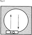
- the discharge head is reciprocated with respect to a workpiece as shown in Fig. 2 and hence, the deformation of the mask can be reduced.
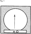
- the deformation of the mask is generated when the discharge head moves in the first direction.
- the discharge head is moved again in the second direction which is the direction opposite to the first direction and hence, the mask which is deformed once returns to an original state. Accordingly, the deformation of the mask can be reduced.
- solder bump forming device for forming a solder bump by applying molten solder into a mask on circular silicon wafer of an electronic component, as defined in claim 5.
- a fluid discharge device for applying fluid into a mask on an electronic component workpiece, as defined in claim 6.
- the suction port degasses and decompresses air in the mask on the workpiece before the fluid is discharged, so that a uniform amount of fluid can be stably discharged.
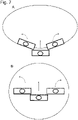
- Split head units may have a size which allows a pressure in the vertical direction applied by the head units to be uniform. To be more specific, it is preferable that the size of each head unit be set to 1/2 to 1/4 of the lateral length of a workpiece. Further, the number of the plurality of head units used in this application may be determined corresponding to the size of a workpiece. The number of head units is appropriately set to 2 to 4 in view of ease of handling. When the fluid is discharged to a workpiece having a circular shape such as a silicon wafer, it is optimal to use three head units. As in the case shown in Fig.
- the head units are horizontally moved in a forward and rearward direction, and angles of the head units disposed on the left and right sides are changed along a circumference of the workpiece.
- the head unit has a shorter length than the workpiece. Accordingly, there is no possibility that a pressure to be applied to a workpiece from the discharge heads is not always uniformly distributed so that an amount of discharge varies. Therefore, a uniform pressure can be applied to the workpiece. Further, the head units move in the horizontal direction above the workpiece in synchronism with each other and hence, there is no discharge leakage whereby the fluid of a stable amount of discharge can be discharged. Accordingly, it is possible to eliminate a large amount of correction which is conventionally required on applying the fluid into a fine mask for a workpiece and hence, productivity can be remarkably enhanced.
- a fluid discharge device for applying fluid on a circular workpiece of an electronic component, as defined in claim 10.
- the discharge heads are configured to move simultaneously in synchronism with each other. A processing time can be shortened.
- the discharge heads are configured to cover, in cooperation with each other, a region on the workpiece where the fluid is to be discharged substantially without causing overlapping.
- the fluid can be efficiently applied. Further, the fluid is not applied to the same portion a plurality of times. Accordingly, a variation in application amount can be suppressed.
- the range in which the fluid can be discharged in each of the discharge heads is set to 1/4 or more and 1/2 or less of a width of the region on the first stage where the workpiece is disposed.
- the advantageous effect of the fourth aspect can be acquired without making the configuration of the device excessively complicated.
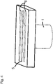
- Fig. 3 is a view showing details of the head unit 1 according to the present invention.
- the head unit 1 includes a fluid tank 2 which can store molten solder or the like, and a discharge head 3 which is formed on a lower end of the head unit 1.
- a heating means may be mounted at the fluid tank 2.
- a heater 4 may be wound around a side portion of the fluid tank 2.
- the discharge head 3 has a fluid discharge nozzle 5 and suction ports 6 which are formed at a lower end of the head.
- the suction ports 6 are formed in the discharge head 3 such that a suction step can be performed prior to a step performed by the fluid discharge nozzle 5 in the traveling direction.
- a heater 4 may also be mounted at a lower end of the discharge head 3.
- a circular shape, a slit shape or any other known shape may be adopted as the shape of a nozzle opening of the discharge head 3. Particularly, with the use of a slit shape as the shape of the nozzle opening, the fluid can be discharged to a plurality of discharge targets on a workpiece 7 simultaneously.
- a circular shape, a slit shape or any other known shape may be adopted also as the shape of the suction port 6 formed in the discharge head 3.
- air or the fluid which has already discharged in a mask 8 can be simultaneously removed with respect to a plurality of portions on the workpiece 7 such as a silicon wafer or a printed circuit board.
- the suction port 6 is formed in front of and behind the discharge head 3 as shown in Fig. 4 so that the deformation of the mask can be made uniform. Accordingly, the fluid can be stably discharged in a reciprocating manner.
- the fluid application device of the present invention is movable in the upward and downward direction (Y) as a whole such that the fluid application device approaches and separates from the electronic component workpiece 7 to which the fluid is to be applied.
- the fluid application device is movable also in the horizontal direction (X).
- the mask 8 which is made from polyimide or a resist is placed on an upper portion of the workpiece 7.
- the discharge head 3 descends to a position where the fluid discharge nozzle 5 comes into contact with the workpiece 7.
- the liquid discharge head 3 moves horizontally while maintaining a contact state between the fluid discharge nozzle 5 and the workpiece 7.
- the fluid discharge device 1 includes the heater 4 for maintaining the fluid in the tank 2 at a desired temperature.
- the heater 4 may be incorporated in a wall portion of the tank 2.
- the heater 4 is managed and controlled so as to heat to an appropriate temperature for maintaining a viscosity of the fluid 9 in the tank 2, such as molten solder, which viscosity is optimal for conditions for applying the fluid 9.
- the fluid discharge device 1 is connected to a pressure supply means 11, which allows fluid communication, through an extension pipeline 10 from the tank 2.
- the fluid discharge device 1 is connected to a reduced pressure supply means 13, which allows fluid communication, through a suction pipe extension pipeline 12 which continues from the suction port 6.
- the pressure supply means 11 includes a pressure generating source 14 which generates a nitrogen gas of a pressure of 0.06 to 0.1 MPa (not limited to such a value), for example.
- the pressure generating source 14 supplies a pressure into the tank 2 through a gate valve 15 and a three-way valve 16. Molten solder held in the tank 2 is injected from the opening of the fluid discharge nozzle 5 by a pressure from the pressure generating source 14.
- the reduced pressure supply means 13 includes a micro ejector 16 which is a reduced pressure generating device.
- the reduced pressure generating device 16 is connected to a pressure generating source 19, which generates a nitrogen gas of a pressure of 0.4 MPa (not limited to such a value), through a regulator 17 and a throttle valve 18, for example.
- the reduced pressure generating device 16 supplies a negative pressure to the suction port 6 through the suction pipe extension pipeline 12.
- the fluid discharge device includes a pressure sensor 20 and a controller 21.
- the pressure sensor 20 is connected to the three-way valve 18 disposed in the extension pipeline 17 in fluid communication with the inside of the tank 2, and the pressure sensor 20 monitors a pressure in the tank 2.
- a signal indicating a pressure in the tank 2 is transmitted to the controller 21 from the pressure sensor 20.
- the controller 21 operates the pressure generating source 14, the reduced pressure generating device 16, the regulator 17, the pressure generating source 19 and the respective valves according to the progress of the operating steps to supply a pressure into the tank 2.
- An appropriate value of pressure required to be supplied is determined based on a signal from the pressure sensor 20.
- a magnitude of positive pressure to be supplied into the tank 2 can be varied by adjusting a value of pressure generated by the pressure generating source 14, for example.
- a value of pressure may be varied by adjusting, with use of the controller 21, a regulating valve (not shown in the drawing) disposed in the pressure supply means 11.
- An appropriate value of pressure, which is required to be supplied into the tank 2, for causing fluid such as molten solder to be injected from the opening of the fluid discharge nozzle 5 or for holding the fluid in the tank 2 is influenced also by an amount (weight) of molten solder stored in the tank 2.
- the controller 21 may be configured to receive data relating to the amount of fluid in the tank 2.
- the controller 21 can calculate an appropriate value of pressure in the tank for injecting the fluid or for hold the fluid in the tank, from the data on the amount of fluid in the tank 2.
- the controller 21 can compare the appropriate value of pressure in the tank and an actual value of pressure in the tank, which the signal from the pressure sensor 20 indicates, to adjust the pressure generating source 14 and the respective valves such that an appropriate pressure in the tank is obtained.
- the fluid supply device 22 may be provided such that the fluid supply device 22 is connected to the tank 2.
- the fluid supply device 22 can automatically supply an additional fluid such that the amount of fluid in the tank 2 is always kept approximately constant. Any known method can be used so as to acquire the amount of fluid in the tank 2.
- the amount of molten solder in the tank 2 can be inferred from the number of products processed or the like.
- the controller 21 can control a pressure which is to be supplied into the tank 2 only based on a signal from the pressure sensor 20.
- the discharge head 3 of the first embodiment is fixed at a fixed position separated from the workpiece 7 at a distance. However, on discharging the fluid, the discharge head 3 moves in the upward and downward direction as well as in the horizontal direction so that the discharge head 3 descends to a position where the discharge head 3 comes into contact with a discharge portion of the mask 8 on the workpiece 7.
- a pressure supplied from the pressure generating source 14 is supplied into the tank 2 through the gate valve 15. The fluid 9 held in the tank 2 is injected from the opening of the discharge nozzle 5 by the pressure from the pressure generating source 14.
- the discharge heads 3 move such that the discharge heads 3 which are discharging the fluid 9 always horizontally move so that the side where the suction nozzle 5 is provided is located forward, and the discharge nozzle 5 discharges the fluid after a pressure of air in an opening portion of the mask 8 on the workpiece 7 is reduced. After discharging the fluid in one direction into the opening portion of the mask 8 on the workpiece 7 is finished, then, the return movement of the discharge head 3 is performed. With such operations, a reciprocating movement of the discharge head 3 is completed. According to the above-mentioned operations, the discharge head 3 discharges the fluid while performing a reciprocating operation with respect to the workpiece 7. Therefore, the deformation of the mask is not biased in one direction so that the deformation of the mask can be reduced.
- a fluid discharge device of the second embodiment The operation of a fluid discharge device of the second embodiment is described.
- Head units 1 in the second embodiment are fixed at fixed positions separated from a workpiece 7 at a distance. However, on discharging the fluid, the head units 1 move in the upward and downward direction as well as in the horizontal direction so that the discharge heads 3 descend to the position where the discharge heads 3 come into contact with discharge portions of a mask 8 on the workpiece 7.
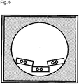
- Fig. 7A illustrates one example showing a state where the plurality of head units 1 descend on discharging the fluid to a silicon wafer.
- the fluid discharge device of the second embodiment includes three head units 1.
- the center head unit is disposed parallel to the traveling direction.
- the left and right head units are disposed along a workpiece having a circular shape, thus being disposed non-parallel to the traveling direction.
- the head units 1 When the head units 1 descend from an initial position, the head units 1 are held in a state where the left head unit is rotated clockwise by 10 to 60 degrees, the center head unit is parallel to the workpiece, and the right head unit is rotated counterclockwise by 10 to 60 degrees. Distal ends of the left and right head units on the center side of the workpiece are disposed forward, in the traveling direction, of the head unit 1 disposed at the center. When the heads move horizontally in the traveling direction, the left head unit turns counterclockwise, and the right head unit turns clockwise so that the left and right head units approach a state parallel to the traveling direction.
- Fig. 7B illustrates one example showing a state where the three head units 1 are in the vicinity of a center portion of a silicon wafer. All of the center, left and right head units 1 are parallel to the traveling direction. When three head units 1 move past the center portion of the silicon wafer, the left head unit turns counterclockwise, and the right head unit turns clockwise.
- Fig. 8C shows a state where the three head units 1 reach a final position. When the head units 1 are at the final position, the head units 1 are held in a state where the left head unit is rotated counterclockwise by 10 to 60 degrees, the center head unit is parallel to the workpiece, and the right head unit is rotated clockwise by 10 to 60 degrees.
- Fig. 8D shows a state where the three head units move to positions outside the silicon wafer to remove the mask. In such a position, in the same manner as the state shown in Fig. 8C , the center head unit is parallel to the traveling direction, and the left and right head units are disposed along the workpiece having a circular shape, thus being non-parallel to the traveling direction.
- the distal ends of the left and right head units on the center side of the workpiece are disposed forward, in the traveling direction, of the head unit disposed at the center.
- the left and right head units of the fluid discharge device of the present invention can turn above a workpiece toward an outer periphery of the workpiece by 10 to 60 degrees on moving from the initial position to the final position.
- the discharge heads 3 moves such that the discharge heads 3 which are discharging the fluid 9 horizontally move so that the side where the suction nozzle 5 is provided is located forward, and the discharge nozzle 5 discharges the fluid after a pressure of air in an opening portion of the mask 8 on the workpiece 7 is reduced.
- a pressure supplied from the pressure generating source 14 is supplied into the tank 2 through a gate valve 15.
- the fluid 9 held in the tank 2 is injected from the opening of the discharge nozzle 5 by a pressure from the pressure generating source 14.
- the discharge heads 3 move horizontally while being in contact with an upper surface of the mask 8 on the workpiece 7, and the application of the fluid within a determined range is completed. According to the above-mentioned operations in this embodiment, the fluid is discharged using the plurality of discharge heads 3 having a smaller size than the workpiece 7. Accordingly, it is possible to suppress variation in the amount of discharge so that the amount of discharge can be stabilized.
- Fig. 9 to 11 show specific example of movement paths of discharge heads 3a to 3c.
- Fig. 9 shows the initial position of the discharge heads 3a to 3c before scanning is performed.
- the first discharge head 3a is disposed outside the workpiece 7.
- the longitudinal direction of the first discharge head 3a is perpendicular to the traveling direction of the first discharge head 3a (the direction toward the upper side of the paper).
- the second discharge heads 3b, 3c are disposed so as to be in contact with an inner periphery of the workpiece 7 having a circular shape. In other words, the second discharge heads 3b, 3c are disposed forward of the first discharge head 3a in the traveling direction.
- the longitudinal directions of the second discharge heads 3b, 3c are inclined with respect to the traveling direction of the discharge heads 3a to 3c (the direction toward the upper side of the paper). Such an inclination may be set to an angle of 10 to 60 degrees with respect to the traveling direction, for example.
- the second discharge head 3b turns counterclockwise as the second discharge head 3b travels in the traveling direction, and the second discharge head 3c turns clockwise as the second discharge head 3c travels in the traveling direction.
- the operation where the second discharge heads 3b, 3c travel in the traveling direction while turning can be realized by a robot arm, for example.
- Fig. 10 shows the discharge heads 3a to 3c at the intermediate position during scanning.
- the first discharge head 3a moves in a straight line from the initial position shown in Fig. 9 to the center of the workpiece 7.
- a reference point RPa of the first discharge head 3a moves along a straight line L1.
- the second discharge heads 3b, 3c travel in the traveling direction from the initial position shown in Fig. 9 while turning so that the second discharge heads 3b, 3c are disposed at the same arrangement angle as the first discharge head 3a. That is, the longitudinal direction of the first discharge head 3a is parallel to the longitudinal directions of the second discharge heads 3b, 3c.
- reference points RPb, RPc of the second discharge heads 3b, 3c respectively move along the straight lines L1, L2.
- the reference points RPb, RPc are set at end portions of the discharge nozzles 5 on the first discharge head 3a side.
- Fig. 11 shows the final position of the discharge heads 3a to 3c after the scanning is finished.
- the first discharge head 3a moves to the position outside the workpiece 7 (the position outside the workpiece 7 on the side opposite to the initial position) from the intermediate position shown in Fig. 10 .
- the second discharge heads 3b, 3c travel in the traveling direction from the intermediate position shown in Fig. 10 while turning so that the second discharge heads 3b, 3c are inclined with respect to the traveling direction of the discharge heads 3a to 3c (the direction toward the upper side of the paper).
- the direction of this inclination is opposite to the direction of the inclination at the initial position.
- This inclination may be set to an angle of 10 to 60 degrees with respect to the traveling direction, for example.
- the discharge heads 3a to 3c move as described above so that the fluid 9 can be applied to approximately the whole region of the workpiece 7.
- the application of the fluid 9 for a center region A1 is covered by the first discharge head 3a.
- the application of the fluid 9 for a left region A2 is covered by the second discharge head 3b on the left side.
- the application of the fluid 9 for a right region A3 is covered by the second discharge head 3c on the right side.
- Fig. 3 is a schematic view showing a schematic configuration of a solder bump forming device which is one example of a fluid application device according to a third embodiment.
- the solder bump forming device is a device which applies fluid 9 (molten solder in this embodiment) on an electronic component workpiece 7 (for example, a silicon wafer, a printed circuit board or the like) to form solder bumps.
- the solder bump forming device includes a discharge head unit 1, a pressure supply means 11, a pressure generating source 14, a micro ejector 16, a pressure generating source 19, and a fluid supply device 22.
- the solder bump forming device also includes stages 30 to 32 (see Fig. 12 ). The details of such configurations are described later.
- Fig. 5 is a schematic view showing the discharge head unit 1 of the solder bump forming device.
- the discharge head unit 1 includes a fluid tank 2 which can store the fluid 9, and a discharge head 3 which is formed on a lower end of the discharge head unit 1.
- the discharge head unit 1 is configured such that the discharge head unit 1 can be moved in the horizontal direction above the workpiece 7 by any actuator (not shown in the drawing).
- the discharge head unit 1 slidingly moves on a mask 8 disposed on the workpiece 7.
- the mask 8 has a plurality of hole portions formed at portions where solder bumps are to be formed. These hole portions penetrate the mask 8 in the thickness direction of the mask 8 (vertical direction).
- the mask 8 may be made from polyimide or a resist, for example.
- the discharge head unit 1 is configured such that the discharge head unit 1 can be moved in the vertical direction, that is, can be moved so as to approach and separate from the workpiece 7.
- the fluid tank 2 may be connected to the fluid supply device 22.
- the fluid supply device 22 can automatically replenish the fluid 9 when the fluid 9 in the tank 2 is consumed, such that the amount of fluid stored in the fluid tank 2 is always kept approximately constant. With such a configuration, it is possible to suppress fluctuations in pressure in the tank which are caused by fluctuations in the amount of fluid stored in the fluid tank 2.
- the discharge head unit 1 includes a heater 4 for maintaining the fluid 9 in the tank 2 at a desired temperature.
- the heater 4 may be incorporated in a wall portion of the tank 2.
- the heater 4 is controlled so as to heat the fluid 9 to an appropriate temperature for maintaining a viscosity of the fluid 9 in the tank 2 which viscosity is optimal for conditions for applying the fluid 9.
- the discharge head 3 has a discharge nozzle 5 and a suction port 6.
- the discharge nozzle 5 penetrates the discharge head 3 in the vertical direction thus communicating with the fluid tank 2.
- the fluid tank 2 is connected to the pressure supply means 11 through an extension pipeline 10.
- the pressure supply means 11 includes a pressure generating source 14 which generates a nitrogen gas of a pressure of 0.06 to 0.1 MPa (not limited to such a value), for example.
- the pressure generating source 14 supplies a pressure to the discharge head unit 1 through a gate valve and a three-way valve. With the supply of such a pressure, the fluid 9 in the tank 2 is discharged from the discharge nozzle 5.
- the suction port 6 penetrates the discharge head 3 in the vertical direction thus communicating with the suction pipe extension pipeline 12.
- the suction pipe extension pipeline 12 is connected to a reduced pressure supply means 13.
- the reduced pressure supply means 13 includes a micro ejector 16 which is a reduced pressure generating device.
- the micro ejector 16 is connected to a pressure generating source 19, which generates a nitrogen gas of a pressure of 0.4 MPa (not limited to such a value), through a regulator and a throttle valve 18, for example.
- the reduced pressure supply means 13 supplies a negative pressure to the suction port 6 through the suction pipe extension pipeline 12.
- the suction port 6 is disposed forward of the discharge nozzle 5 in the traveling direction of the discharge head unit 1. Accordingly, the inside of the hole portions of the mask 8 can be degassed and decompressed through the suction port 6 before the fluid is discharged from the discharge nozzle 5. With such a configuration, a uniform amount of fluid can be stably discharged.
- a circular shape, a slit shape or any other known shape may be adopted as the shape of an opening of the discharge nozzle 5. Particularly, when a slit shape is adopted as the shape of the opening of the discharge nozzle 5, the fluid can be discharged into a plurality of hole portions of the mask 8 simultaneously.
- a circular shape, a slit shape or any other known shape may be adopted also as the shape of an opening of the suction port 6. When a slit shape is adopted as the shape of the opening of the suction port 6, air and the fluid which has already discharged can be sucked at a plurality of portions simultaneously.
- the discharge head unit 1 descends to a position where the discharge head 3 (that is, the opening portion positioned at the lower end of the discharge nozzle 5) comes into contact with the mask 8. Then, the discharge head 3 moves in the horizontal direction while maintaining a contact state between the discharge nozzle 5 and the mask 8. When the discharge head 3 moves horizontally, first, air in the hole portions of the mask 8 disposed on the workpiece 7 is sucked through the suction port 6 formed on the forward side of the discharge head 3 in the traveling direction.
- the discharge head 3 scans above the same hole portion a plurality of times, the fluid 9 previously discharged into the hole portion is also sucked at this stage of operation.
- a heater may be disposed at a lower portion of the discharge head 3. With such a configuration, the fluid 9 previously discharged into the hole portion is not solidified. Accordingly, the fluid can be reliably sucked.
- the discharge head 3 further moves horizontally, the fluid 9 is discharged from the opening of the discharge nozzle 5 into the hole portions of the mask 8 after the suction operation is performed by the suction port 6. With such operations, the fluid 9 is applied into the hole portions of the mask 8 on the workpiece 7.
- the discharge head 3 is raised so as to separate from the mask 8. The same step may be performed also in the case where the mask 8 is not used.
- Fig. 12 is a top plan view showing the arrangement of the discharge head units 1, the first stage 30 and the second stages 31, 32.
- the solder bump forming device of this embodiment includes three discharge heads 3a to 3c.
- the actual solder bump forming device also includes three discharge head units 1. However, the illustration of these discharge head units 1 is omitted in Fig. 12 .
- the illustration of the mask 8 is also omitted.
- the discharge head 3a is also referred to as "first discharge head 3a”
- the discharge heads 3b, 3c are also referred to as "second discharge heads 3b, 3c”.
- the solder bump forming device also includes a first stage 30 for supporting the workpiece 7, and second stages 31, 32 disposed outside the first stage 30.
- the first stage 30 has a circular shape slightly larger than the workpiece 7 having a circular shape.
- the first stage 30 may have any shape corresponding to the shape of the workpiece 7.
- the second stages 31, 32 are disposed so as to opposedly face both ends of the first stage 30 in the radial direction such that the second stages 31, 32 are in contact with an outer edge of the first stage 30.
- the second stages 31, 32 have a rectangular shape.
- the second stages 31, 32 may have any shape which extends to the outer edge of the first stage 30.
- the second stages 31, 32 may have a recessed shape having an arc which conforms to an arc shape of the outer edge of the first stage 30.
- Fig. 13 is a cross-sectional view showing the arrangement of the first stage 30 and the second stages 31, 32.
- the first stage 30 has a recessed portion for disposing the workpiece 7 at the center of the first stage 30.
- the recessed portion is formed to have a size at which an upper end of the recessed portion and an upper end of the mask 8 are flush with each other when the workpiece 7 and the mask 8 are disposed in the recessed portion.
- upper ends of the second stage 31 and 32 are disposed at the same height as the upper end of the recessed portion of the first stage 30 and the upper end of the mask 8.
- the first discharge head 3a is configured to move in the horizontal direction above the workpiece 7. To be more specific, the first discharge head 3a moves in a straight line while passing through the center of the workpiece 7 from an initial position disposed outside the first stage 30 (a position on the second stage 31) to a final position disposed outside the first stage 30 (a position on the second stage 32).
- the second discharge heads 3b, 3c are respectively disposed on both sides of the first discharge head 3a.
- the second discharge heads 3b, 3c move above the workpiece 7 in the same traveling direction as the first discharge head 3a while changing arrangement angles of the second discharge heads 3b, 3c.
- All of widths of the discharge heads 3a to 3c in the longitudinal direction are smaller than the width of the workpiece 7 (in other words, a region where the workpiece 7 is disposed).
- the discharge heads 3a to 3c apply the fluid 9 to the whole region of the workpiece 7 in cooperation with each other.
- the discharge heads 3a to 3c respectively apply the fluid 9 to different regions so that the fluid 9 is applied to the whole region of the workpiece 7.
- the width of each of the discharge heads 3a to 3c may be 1/4 or more and 1/2 or less of the width of the region where the workpiece 7 is disposed. With such a configuration, the fluid 9 can be uniformly applied without making the configuration of the device excessively complicated.
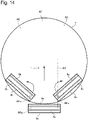
- Fig. 14 to 16 show specific examples of movement paths of the discharge heads 3a to 3c.
- Fig. 14 shows the initial position of the discharge heads 3a to 3c before scanning is performed.
- the first discharge head 3a is disposed on the second stage 31 (not shown in Fig. 14 ).
- the longitudinal direction of the first discharge head 3a is perpendicular to the traveling direction of the first discharge head 3a (the direction toward the upper side of the paper).
- the second discharge heads 3b, 3c are disposed so as to be in contact with an inner periphery of the workpiece 7 having a circular shape. In other words, the second discharge heads 3b, 3c are disposed forward of the first discharge head 3a in the traveling direction.
- the longitudinal directions of the second discharge heads 3b, 3c are inclined with respect to the traveling direction of the discharge heads 3a to 3c (the direction toward the upper side of the paper). Such an inclination may be set to an angle of 10 to 60 degrees with respect to the traveling direction, for example.
- the second discharge head 3b turns counterclockwise as the second discharge head 3b travels in the traveling direction.
- the second discharge head 3c turns clockwise as the second discharge head 3c travels in the traveling direction.
- the operation where the second discharge heads 3b, 3c travel in the traveling direction while turning can be realized by a robot arm, for example.
- Fig. 15 shows the discharge heads 3a to 3c at the intermediate position during scanning.
- the first discharge head 3a moves in a straight line from the initial position shown in Fig. 14 to the center of the workpiece 7.
- a reference point RPa of the first discharge head 3a moves along a straight line L1.
- the second discharge heads 3b, 3c travel in the traveling direction from the initial position shown in Fig. 14 while turning so that the second discharge heads 3b, 3c are disposed at the same arrangement angle as the first discharge head 3a. That is, the longitudinal direction of the first discharge head 3a is parallel to the longitudinal directions of the second discharge heads 3b, 3c.
- reference points RPb, RPc of the second discharge heads 3b, 3c respectively move along the straight lines L1, L2.
- the reference points RPb, RPc are set at end portions of the discharge nozzles 5 on the first discharge head 3a side.
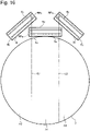
- Fig. 16 shows a final position of the discharge heads 3a to 3c after the scanning is finished.
- the first discharge head 3a moves from the intermediate position shown in Fig. 15 to the position on the second stage 32 (not shown in Fig. 16 ).
- the second discharge heads 3b, 3c travel in the traveling direction from the intermediate position shown in Fig. 15 while turning so that the second discharge heads 3b, 3c are inclined with respect to the traveling direction of the discharge heads 3a to 3c (the direction toward the upper side of the paper).
- the directions of the inclinations are opposite to the directions of the inclinations at the initial position.
- the inclinations may be set to an angle of 10 to 60 degrees with respect to the traveling direction, for example.
- the discharge heads 3a to 3c move as described above so that the fluid 9 can be applied to approximately the whole region of the workpiece 7.
- the application of the fluid 9 for a center region A1 is covered by the first discharge head 3a.
- the application of the fluid 9 for a left region A2 is covered by the second discharge head 3b on the left side.
- the application of the fluid 9 for a right region A3 is covered by the second discharge head 3c on the right side.
- the above-mentioned movements of the discharge heads 3a to 3c may be simultaneously performed in synchronism with each other. By performing the operation in such a manner, a processing time for the workpiece 7 can be shortened. However, after the movement of at least one of the discharge heads 3 a to 3c is finished, the movement of the remaining of the discharge heads 3a to 3c may be started.
- the fluid 9 is discharged using the plurality of discharge heads 3a to 3c having a smaller size than the workpiece 7. Accordingly, even when a workpiece 7 has a large size, a pressure to be applied to the workpiece 7 from the respective discharge heads 3a to 3c is approximately uniformly distributed. Therefore, the amount of discharge of fluid 9 can be made uniform. Further, the second stages 31, 32 are disposed on the movement path of the first discharge head 3a at positions outside the first stage 30 and hence, the first discharge head 3a can apply the fluid from an outer edge to another outer edge of the workpiece 7.
- the second discharge heads 3b, 3c move while changing arrangement angles thereof and hence, even when the application is started from a position above the workpiece 7, the fluid 9 can be discharged in a wide range. Accordingly, the fluid 9 can be discharged over a wide range region of the workpiece 7. Particularly, as in the case of this embodiment, with the use of one first discharge head 3a and two second discharge heads 3b, 3c, the fluid can be efficiently applied to approximately the whole region of the workpiece 7 having a circular shape.
- the number of discharge heads 3 may be set to any number of 2 or more according to the size or the shape of the workpiece 7.
Landscapes
- Engineering & Computer Science (AREA)
- Manufacturing & Machinery (AREA)
- Microelectronics & Electronic Packaging (AREA)
- Mechanical Engineering (AREA)
- Computer Hardware Design (AREA)
- Power Engineering (AREA)
- Life Sciences & Earth Sciences (AREA)
- Wood Science & Technology (AREA)
- Coating Apparatus (AREA)
- Application Of Or Painting With Fluid Materials (AREA)
Claims (14)
- Procédé destiné à éjecter un fluide en vue d'appliquer le fluide à l'intérieur d'un masque (8) sur une pièce de fabrication circulaire (7) d'un composant électronique, le procédé comprenantl'utilisation d'un dispositif d'éjection de fluide comportant une unité de tête (1), l'unité de tête (1) comportant un réservoir (2) pouvant stocker le fluide et pourvu d'un premier élément chauffant (4), et une tête d'éjection (3, 3a, 3b, 3c) pour éjecter le fluide depuis une buse d'éjection (5) par va-et-vient de la tête d'éjection (3, 3a, 3b, 3c) par rapport à la pièce de fabrication (7), après aspiration d'air ou du fluide dans le masque (8) depuis un orifice d'aspiration (6), dans lequell'unité de tête (1) a une largeur longitudinale plus courte qu'un diamètre de la pièce de fabrication (7),la tête d'éjection (3, 3a, 3b, 3c) a l'orifice d'aspiration (6) pour aspirer une substance dans le masque (8) sur la pièce de fabrication (7) formé sur un côté avant d'une direction de déplacement de la tête d'éjection (3, 3a, 3b, 3c), et la buse d'éjection (5) pour éjecter le fluide formée sur un côté arrière de la direction de déplacement, etun deuxième élément chauffant est disposé à une extrémité inférieure de la buse d'éjection (5).
- Procédé d'éjection du fluide selon la revendication 1, dans lequel le deuxième élément chauffant est configuré pour chauffer le fluide dans le masque (8).
- Procédé d'éjection du fluide selon la revendication 1, dans lequel la tête d'éjection (3, 3a, 3b, 3c) a des parties d'ouverture ayant une forme de fente comme forme de la buse d'éjection (5) et de l'orifice d'aspiration (6) .
- Procédé d'éjection du fluide selon la revendication 1, dans lequel l'orifice d'aspiration (6) est disposé sur les deux côtés de la buse d'éjection (5) dans la tête d'éjection (3, 3a, 3b, 3c).
- Dispositif de formation de plot de soudure destiné à former un plot de soudure en appliquant de la brasure fondue à l'intérieur d'un masque (8) sur une tranche de silicium circulaire d'un composant électronique, le dispositif de formation de plot de soudure comprenantune unité de tête (1) comportant un réservoir (2) pouvant stocker la brasure fondue et pourvu d'un premier élément chauffant (4), et une tête d'éjection (3, 3a, 3b, 3c), dans lequell'unité de tête (1) a une largeur longitudinale plus courte qu'un diamètre de la tranche de silicium,la tête d'éjection (3, 3a, 3b, 3c) a une buse d'éjection (5) pour éjecter la brasure fondue, et un orifice d'aspiration (6) formé à proximité de la buse d'éjection (5) sur les deux côtés de la buse d'éjection (5) et ayant une partie d'ouverture ayant une forme de fente pour aspirer une substance dans le masque (8) sur la tranche de silicium,la tête d'éjection (3, 3a, 3b, 3c) est configurée pour se déplacer au-dessus du masque (8) de manière à éjecter la brasure fondue depuis la buse d'éjection (5) après décompression d'air dans une partie d'ouverture du masque (8) par aspiration de l'air à travers l'orifice d'aspiration (6), etun deuxième élément chauffant est disposé à une extrémité inférieure de la buse d'éjection (5), le deuxième élément chauffant étant configuré pour chauffer la brasure dans le masque (8).
- Dispositif d'éjection de fluide destiné à appliquer un fluide à l'intérieur d'un masque (8) sur une pièce de fabrication circulaire (7) d'un composant électronique, le dispositif d'éjection de fluide comprenantune pluralité d'unités de tête (1) ayant chacune une largeur longitudinale plus courte qu'un diamètre de la pièce de fabrication (7), dans lequella pluralité d'unités de tête incluent une première unité de tête (1) configurée pour se déplacer en ligne droite dans une direction horizontale au-dessus de la pièce de fabrication (7), et une deuxième unité de tête (1) configurée pour se déplacer dans la direction horizontale au-dessus de la pièce de fabrication (7) en synchronisation avec la première unité de tête (1) tout en tournant,chacune des première et deuxième unités de tête (1) comporte un réservoir (2) pouvant stocker le fluide et pourvu d'un premier élément chauffant (4), et une tête d'éjection (3, 3a, 3b, 3c),chaque tête d'éjection (3, 3a, 3b, 3c) a un orifice d'aspiration (6) pour aspirer une substance dans le masque (8) sur la pièce de fabrication (7) formé sur un côté avant d'une direction de déplacement de la tête d'éjection (3, 3a, 3b, 3c), et une buse d'éjection (5) pour éjecter le fluide formée sur un côté arrière de la direction de déplacement, etun deuxième élément chauffant est disposé à proximité de la buse d'éjection (5) et de l'orifice d'aspiration (6),chaque tête d'éjection (3, 3a, 3b, 3c) est configurée pour éjecter le fluide depuis la buse d'éjection (5) et effectuer simultanément une aspiration à travers l'orifice d'aspiration (6) tout en se déplaçant dans la direction horizontale au-dessus de la pièce de fabrication (7).
- Dispositif d'éjection de fluide selon la revendication 6, dans lequel la deuxième unité de tête (1) comporte deux deuxièmes unités de tête (1) disposées sur les deux côtés de la première unité de tête (1).
- Dispositif d'éjection de fluide selon la revendication 6, dans lequel l'orifice d'aspiration (6) comporte deux orifices d'aspiration (6) disposés sur les deux côtés de la buse d'éjection (5).
- Dispositif d'éjection de fluide selon la revendication 7, dans lequel les deux deuxièmes unités de tête (1) incluent une unité de tête (1) configurée pour tourner dans le sens antihoraire, et une unité de tête (1) configurée pour tourner dans le sens horaire.
- Dispositif d'éjection de fluide destiné à appliquer un fluide sur une pièce de fabrication circulaire (7) d'un composant électronique, le dispositif d'éjection de fluide comprenant :une platine (30) pour supporter la pièce de fabrication (7) ; etdes première à troisième têtes d'éjection (3, 3a, 3b, 3c) configurées pour éjecter le fluide tout en se déplaçant dans une direction horizontale au-dessus de la platine (30), dans lequella première tête d'éjection (3a) est configurée pour se déplacer en ligne droite depuis une position initiale située à l'extérieur de la platine (30) jusqu'à une position finale située à l'extérieur de la platine (30) à travers une zone au-dessus de la platine (30),la deuxième tête d'éjection (3b) est disposée sur un côté gauche tel qu'observé dans une direction de déplacement de la première tête d'éjection (3a), et configurée pour éjecter le fluide tout en tournant dans le sens antihoraire et en se déplaçant dans la direction horizontale au-dessus de la platine (30),la troisième tête d'éjection (3c) est disposée sur un côté droit tel qu'observé dans la direction de déplacement de la première tête d'éjection (3a), et configurée pour éjecter le fluide tout en tournant dans le sens horaire et en se déplaçant dans la direction horizontale au-dessus de la platine (30),une étendue sur laquelle le fluide peut être éjecté dans chacune des première à troisième têtes d'éjection (3, 3a, 3b, 3c) est plus petite qu'une largeur d'une région sur la platine (30) où la pièce de fabrication (7) est disposée.
- Dispositif d'éjection de fluide selon la revendication 10, dans lequelun point de référence est défini dans chacune des deuxième et troisième têtes d'éjection (3b, 3c) au niveau de parties d'extrémité, sur le côté de la première tête d'éjection, des buses d'éjection (5) formées dans les deuxième et troisième têtes d'éjection (3b, 3c), etchaque point de référence trace une trajectoire en ligne droite le long d'une direction de déplacement des deuxième et troisième têtes d'éjection (3b, 3c) quand les deuxième et troisième têtes d'éjection (3b, 3c) se déplacent.
- Dispositif d'éjection de fluide selon la revendication 10 ou la revendication 11, dans lequel les première à troisième têtes d'éjection (3, 3a, 3b, 3c) sont configurées pour se déplacer simultanément en synchronisation les unes avec les autres.
- Dispositif d'éjection de fluide selon l'une quelconque des revendications 10 à 12, dans lequel les première à troisième têtes d'éjection (3, 3a, 3b, 3c) sont configurées pour couvrir, en coopération les unes avec les autres, une région sur la pièce de fabrication (7) où le fluide doit être éjecté sensiblement sans provoquer de chevauchement.
- Dispositif d'éjection de fluide selon l'une quelconque des revendications 10 à 13, dans lequel l'étendue sur laquelle le fluide peut être éjecté dans chacune des première à troisième têtes d'éjection (3, 3a, 3b, 3c) représente 1/4 ou plus et 1/2 ou moins d'une largeur de la région sur la première platine (30) où la pièce de fabrication (7) est disposée.
Applications Claiming Priority (4)
| Application Number | Priority Date | Filing Date | Title |
|---|---|---|---|
| JP2015244141 | 2015-12-15 | ||
| JP2015244139 | 2015-12-15 | ||
| JP2016165458 | 2016-08-26 | ||
| PCT/JP2016/087369 WO2017104745A1 (fr) | 2015-12-15 | 2016-12-15 | Dispositif de distribution de fluide et procédé de distribution de fluide |
Publications (3)
| Publication Number | Publication Date |
|---|---|
| EP3391974A1 EP3391974A1 (fr) | 2018-10-24 |
| EP3391974A4 EP3391974A4 (fr) | 2019-08-07 |
| EP3391974B1 true EP3391974B1 (fr) | 2022-06-01 |
Family
ID=59056589
Family Applications (1)
| Application Number | Title | Priority Date | Filing Date |
|---|---|---|---|
| EP16875722.7A Active EP3391974B1 (fr) | 2015-12-15 | 2016-12-15 | Dispositif de distribution de fluide et procédé de distribution de fluide |
Country Status (8)
| Country | Link |
|---|---|
| US (2) | US10932372B2 (fr) |
| EP (1) | EP3391974B1 (fr) |
| JP (2) | JP6579343B2 (fr) |
| KR (1) | KR102596840B1 (fr) |
| CN (1) | CN108602088B (fr) |
| HU (1) | HUE059602T2 (fr) |
| TW (2) | TWI708348B (fr) |
| WO (1) | WO2017104745A1 (fr) |
Families Citing this family (2)
| Publication number | Priority date | Publication date | Assignee | Title |
|---|---|---|---|---|
| US11298769B2 (en) * | 2019-05-13 | 2022-04-12 | International Business Machines Corporation | Prevention of dripping of material for material injection |
| CN113993295B (zh) * | 2021-10-13 | 2023-04-25 | 苏州康尼格电子科技股份有限公司 | 一种pcba板封装设备 |
Family Cites Families (48)
| Publication number | Priority date | Publication date | Assignee | Title |
|---|---|---|---|---|
| JPS55154798A (en) | 1979-05-21 | 1980-12-02 | Sony Corp | Apparatus for fabricating hybrid integrated circuit |
| US4517917A (en) * | 1984-04-26 | 1985-05-21 | Valco Cincinnati, Inc. | Blow-off manifold for preventing trailing from a non-contact extrusion adhesive application valve |
| US4898117A (en) | 1988-04-15 | 1990-02-06 | International Business Machines Corporation | Solder deposition system |
| US4934309A (en) | 1988-04-15 | 1990-06-19 | International Business Machines Corporation | Solder deposition system |
| US5418009A (en) * | 1992-07-08 | 1995-05-23 | Nordson Corporation | Apparatus and methods for intermittently applying discrete adhesive coatings |
| JPH06151296A (ja) | 1992-11-11 | 1994-05-31 | Yamaha Corp | 加圧塗布方法及び装置 |
| US5478700A (en) * | 1993-12-21 | 1995-12-26 | International Business Machines Corporation | Method for applying bonding agents to pad and/or interconnection sites in the manufacture of electrical circuits using a bonding agent injection head |
| US6231333B1 (en) * | 1995-08-24 | 2001-05-15 | International Business Machines Corporation | Apparatus and method for vacuum injection molding |
| US6149076A (en) * | 1998-08-05 | 2000-11-21 | Nordson Corporation | Dispensing apparatus having nozzle for controlling heated liquid discharge with unheated pressurized air |
| US6461136B1 (en) * | 1999-08-26 | 2002-10-08 | International Business Machines Corp. | Apparatus for filling high aspect ratio via holes in electronic substrates |
| FI115295B (fi) * | 1999-09-01 | 2005-04-15 | Metso Paper Inc | Verhopäällystin ja verhopäällystysmenetelmä |
| FR2803228B1 (fr) | 2000-01-03 | 2002-02-08 | Novatec Sa Soc | Dispositif de remplissage collectif de cavites borgnes |
| US6544590B1 (en) | 2000-01-17 | 2003-04-08 | Canon Kabushiki Kaisha | Liquid coating method, apparatus and film-forming method for producing the same employing excess coating removing unit having absorbent fabric on porous structure |
| JP2001269610A (ja) | 2000-01-17 | 2001-10-02 | Canon Inc | 塗布方法、塗布装置および被膜の作製方法 |
| US6638363B2 (en) * | 2000-11-22 | 2003-10-28 | Gunter Erdmann | Method of cleaning solder paste |
| JP3957983B2 (ja) | 2001-03-01 | 2007-08-15 | 大日本スクリーン製造株式会社 | 基板現像装置 |
| US6692165B2 (en) | 2001-03-01 | 2004-02-17 | Dainippon Screen Mfg. Co., Ltd. | Substrate processing apparatus |
| JP3849545B2 (ja) * | 2002-02-26 | 2006-11-22 | セイコーエプソン株式会社 | 薄膜形成装置と薄膜形成方法、回路パターンの製造装置と回路パターンの製造方法と電子機器、及びレジストパターンの製造装置とレジストパターンの製造方法 |
| US20040202863A1 (en) * | 2002-02-26 | 2004-10-14 | Konica Corporation | Coating method, coated product and ink jet recording medium |
| JP3619874B2 (ja) | 2002-07-05 | 2005-02-16 | 国立大学法人京都大学 | 温度応答性ポリマー及び温度応答性ゲル状ポリマー |
| JP4127008B2 (ja) | 2002-10-03 | 2008-07-30 | セイコーエプソン株式会社 | 液滴吐出装置及び方法、デバイスの製造装置、デバイス製造方法、並びに電子機器 |
| JP4432322B2 (ja) | 2003-01-20 | 2010-03-17 | セイコーエプソン株式会社 | 液滴吐出装置 |
| JP3772155B2 (ja) | 2003-04-01 | 2006-05-10 | 株式会社タムラ製作所 | 液体噴射装置 |
| JP2004337704A (ja) | 2003-05-14 | 2004-12-02 | Seiko Epson Corp | 液滴吐出装置 |
| KR100958573B1 (ko) * | 2003-10-06 | 2010-05-18 | 엘지디스플레이 주식회사 | 액정표시패널의 제조장치 및 제조방법 |
| JP2005183542A (ja) | 2003-12-17 | 2005-07-07 | Fujikura Ltd | プリント配線板のはんだコーティング方法 |
| JP2005246139A (ja) | 2004-03-01 | 2005-09-15 | Seiko Epson Corp | 流動材料塗布方法、流動材料塗布装置および電子機器 |
| US7354869B2 (en) | 2004-04-13 | 2008-04-08 | Kabushiki Kaisha Toshiba | Substrate processing method, substrate processing apparatus, and semiconductor device manufacturing method |
| JP2006013228A (ja) | 2004-06-28 | 2006-01-12 | Toshiba Corp | 基板処理方法及び基板処理装置 |
| JP4271109B2 (ja) * | 2004-09-10 | 2009-06-03 | 東京エレクトロン株式会社 | 塗布、現像装置、レジストパターン形成方法、露光装置及び洗浄装置 |
| US7291226B2 (en) * | 2004-09-30 | 2007-11-06 | Lexmark International, Inc. | Progressive stencil printing |
| KR100780718B1 (ko) * | 2004-12-28 | 2007-12-26 | 엘지.필립스 엘시디 주식회사 | 도포액 공급장치를 구비한 슬릿코터 |
| US8287647B2 (en) * | 2007-04-17 | 2012-10-16 | Lam Research Corporation | Apparatus and method for atomic layer deposition |
| US20080268164A1 (en) * | 2007-04-26 | 2008-10-30 | Air Products And Chemicals, Inc. | Apparatuses and Methods for Cryogenic Cooling in Thermal Surface Treatment Processes |
| DE102007053513B3 (de) * | 2007-11-09 | 2009-07-16 | Itc Intercircuit Electronic Gmbh | Füllanlage |
| CN103097138B (zh) * | 2010-04-05 | 2017-04-05 | Dtg国际有限公司 | 丝网清洁装置及方法 |
| JP2012139655A (ja) | 2011-01-05 | 2012-07-26 | Seiko Epson Corp | 印刷装置 |
| TWI552824B (zh) | 2011-10-18 | 2016-10-11 | 千住金屬工業股份有限公司 | 焊料凸塊形成方法及裝置 |
| US8789490B2 (en) * | 2012-01-20 | 2014-07-29 | Sso Venture Partners, Llc | System and method of pointillist painting |
| US9427768B2 (en) * | 2012-10-26 | 2016-08-30 | Nordson Corporation | Adhesive dispensing system and method with melt on demand at point of dispensing |
| JP5732023B2 (ja) | 2012-10-31 | 2015-06-10 | ヤマハ発動機株式会社 | 半田供給方法、半田供給装置 |
| US9278401B2 (en) * | 2013-02-11 | 2016-03-08 | International Business Machines Corporation | Fill head interface with combination vacuum pressure chamber |
| JP2014157863A (ja) * | 2013-02-14 | 2014-08-28 | Tokyo Electron Ltd | 金属ペースト充填方法及び金属ペースト充填装置 |
| JP6393462B2 (ja) | 2013-09-11 | 2018-09-19 | 東レエンジニアリング株式会社 | エレクトロスプレー装置 |
| JP6276552B2 (ja) * | 2013-10-04 | 2018-02-07 | ファスフォードテクノロジ株式会社 | ダイボンダ及び接着剤塗布方法 |
| WO2016114275A1 (fr) | 2015-01-13 | 2016-07-21 | 千住金属工業株式会社 | Dispositif d'évacuation de fluide, procédé d'évacuation de fluide, et dispositif d'application de fluide |
| KR20180095864A (ko) * | 2015-12-15 | 2018-08-28 | 센주긴조쿠고교 가부시키가이샤 | 땜납 범프의 수정 방법 |
| JP2017109211A (ja) * | 2015-12-15 | 2017-06-22 | 千住金属工業株式会社 | 流体吐出方法および流体吐出装置 |
-
2016
- 2016-12-15 HU HUE16875722A patent/HUE059602T2/hu unknown
- 2016-12-15 KR KR1020187020103A patent/KR102596840B1/ko active IP Right Grant
- 2016-12-15 TW TW109114554A patent/TWI708348B/zh active
- 2016-12-15 CN CN201680074153.8A patent/CN108602088B/zh active Active
- 2016-12-15 TW TW105141593A patent/TWI708346B/zh active
- 2016-12-15 US US16/063,155 patent/US10932372B2/en active Active
- 2016-12-15 EP EP16875722.7A patent/EP3391974B1/fr active Active
- 2016-12-15 JP JP2017556439A patent/JP6579343B2/ja active Active
- 2016-12-15 WO PCT/JP2016/087369 patent/WO2017104745A1/fr active Application Filing
-
2019
- 2019-05-24 JP JP2019097444A patent/JP6687874B2/ja active Active
-
2021
- 2021-01-21 US US17/153,978 patent/US11259415B2/en active Active
Also Published As
| Publication number | Publication date |
|---|---|
| KR20180098581A (ko) | 2018-09-04 |
| TWI708346B (zh) | 2020-10-21 |
| JP2019166522A (ja) | 2019-10-03 |
| EP3391974A1 (fr) | 2018-10-24 |
| TW201731053A (zh) | 2017-09-01 |
| JP6687874B2 (ja) | 2020-04-28 |
| EP3391974A4 (fr) | 2019-08-07 |
| JP6579343B2 (ja) | 2019-09-25 |
| US20210144863A1 (en) | 2021-05-13 |
| KR102596840B1 (ko) | 2023-11-02 |
| US20180376600A1 (en) | 2018-12-27 |
| WO2017104745A1 (fr) | 2017-06-22 |
| TWI708348B (zh) | 2020-10-21 |
| CN108602088B (zh) | 2022-10-14 |
| TW202034479A (zh) | 2020-09-16 |
| CN108602088A (zh) | 2018-09-28 |
| US11259415B2 (en) | 2022-02-22 |
| HUE059602T2 (hu) | 2022-11-28 |
| JPWO2017104745A1 (ja) | 2018-11-15 |
| US10932372B2 (en) | 2021-02-23 |
Similar Documents
| Publication | Publication Date | Title |
|---|---|---|
| US10632492B2 (en) | Fluid discharge device, fluid discharge method, and fluid application device | |
| US11259415B2 (en) | Method for discharging fluid | |
| KR20100053518A (ko) | 기판을 처리하기 위해 제어된 메니스커스를 갖는 단상 근접 헤드 | |
| JP2020115574A (ja) | はんだバンプの修正方法 | |
| CN108325788B (zh) | 涂敷装置以及涂敷方法 | |
| JP2017527436A (ja) | ディスペンサ用の弁座 | |
| JP2004089771A (ja) | 塗布装置および塗布方法 | |
| JP6033712B2 (ja) | 塗布膜形成方法および塗布装置 | |
| JP2018086637A (ja) | 絶縁膜材料の塗布方法 | |
| CN108025328A (zh) | 涂布方法 | |
| CN216389267U (zh) | 喷嘴待机装置以及液处理装置 | |
| JP2017228641A (ja) | 膜パターン形成方法 |
Legal Events
| Date | Code | Title | Description |
|---|---|---|---|
| STAA | Information on the status of an ep patent application or granted ep patent |
Free format text: STATUS: THE INTERNATIONAL PUBLICATION HAS BEEN MADE |
|
| PUAI | Public reference made under article 153(3) epc to a published international application that has entered the european phase |
Free format text: ORIGINAL CODE: 0009012 |
|
| STAA | Information on the status of an ep patent application or granted ep patent |
Free format text: STATUS: REQUEST FOR EXAMINATION WAS MADE |
|
| 17P | Request for examination filed |
Effective date: 20180702 |
|
| AK | Designated contracting states |
Kind code of ref document: A1 Designated state(s): AL AT BE BG CH CY CZ DE DK EE ES FI FR GB GR HR HU IE IS IT LI LT LU LV MC MK MT NL NO PL PT RO RS SE SI SK SM TR |
|
| AX | Request for extension of the european patent |
Extension state: BA ME |
|
| DAV | Request for validation of the european patent (deleted) | ||
| DAX | Request for extension of the european patent (deleted) | ||
| A4 | Supplementary search report drawn up and despatched |
Effective date: 20190709 |
|
| RIC1 | Information provided on ipc code assigned before grant |
Ipc: H05K 3/14 20060101ALI20190703BHEP Ipc: B23K 101/42 20060101ALI20190703BHEP Ipc: B23K 1/20 20060101ALI20190703BHEP Ipc: H01L 21/60 20060101ALI20190703BHEP Ipc: B05D 7/00 20060101ALI20190703BHEP Ipc: B23K 1/00 20060101ALI20190703BHEP Ipc: B05D 1/26 20060101AFI20190703BHEP Ipc: H05K 3/28 20060101ALI20190703BHEP Ipc: B05C 5/02 20060101ALI20190703BHEP Ipc: H05K 3/10 20060101ALI20190703BHEP Ipc: B23K 3/06 20060101ALI20190703BHEP Ipc: B23K 101/40 20060101ALI20190703BHEP Ipc: B05D 3/12 20060101ALI20190703BHEP Ipc: B05C 11/10 20060101ALI20190703BHEP Ipc: H05K 3/34 20060101ALI20190703BHEP Ipc: B05C 21/00 20060101ALI20190703BHEP |
|
| REG | Reference to a national code |
Ref country code: DE Ref legal event code: R079 Ref document number: 602016072598 Country of ref document: DE Free format text: PREVIOUS MAIN CLASS: B05D0001260000 Ipc: H01L0023000000 |
|
| GRAP | Despatch of communication of intention to grant a patent |
Free format text: ORIGINAL CODE: EPIDOSNIGR1 |
|
| STAA | Information on the status of an ep patent application or granted ep patent |
Free format text: STATUS: GRANT OF PATENT IS INTENDED |
|
| RIC1 | Information provided on ipc code assigned before grant |
Ipc: B23K 101/42 20060101ALI20211125BHEP Ipc: B23K 101/40 20060101ALI20211125BHEP Ipc: B23K 1/20 20060101ALI20211125BHEP Ipc: H05K 3/34 20060101ALI20211125BHEP Ipc: H05K 3/28 20060101ALI20211125BHEP Ipc: H05K 3/10 20060101ALI20211125BHEP Ipc: B05D 1/26 20060101ALI20211125BHEP Ipc: B05C 21/00 20060101ALI20211125BHEP Ipc: B05C 11/10 20060101ALI20211125BHEP Ipc: B05C 5/02 20060101ALI20211125BHEP Ipc: B23K 3/06 20060101ALI20211125BHEP Ipc: B05D 7/00 20060101ALI20211125BHEP Ipc: B05D 3/12 20060101ALI20211125BHEP Ipc: B23K 101/00 20060101ALI20211125BHEP Ipc: B23K 1/00 20060101ALI20211125BHEP Ipc: H01L 23/00 20060101AFI20211125BHEP |
|
| INTG | Intention to grant announced |
Effective date: 20211220 |
|
| GRAS | Grant fee paid |
Free format text: ORIGINAL CODE: EPIDOSNIGR3 |
|
| GRAA | (expected) grant |
Free format text: ORIGINAL CODE: 0009210 |
|
| STAA | Information on the status of an ep patent application or granted ep patent |
Free format text: STATUS: THE PATENT HAS BEEN GRANTED |
|
| AK | Designated contracting states |
Kind code of ref document: B1 Designated state(s): AL AT BE BG CH CY CZ DE DK EE ES FI FR GB GR HR HU IE IS IT LI LT LU LV MC MK MT NL NO PL PT RO RS SE SI SK SM TR |
|
| REG | Reference to a national code |
Ref country code: GB Ref legal event code: FG4D |
|
| REG | Reference to a national code |
Ref country code: AT Ref legal event code: REF Ref document number: 1495980 Country of ref document: AT Kind code of ref document: T Effective date: 20220615 Ref country code: CH Ref legal event code: EP Ref country code: DE Ref legal event code: R096 Ref document number: 602016072598 Country of ref document: DE |
|
| REG | Reference to a national code |
Ref country code: IE Ref legal event code: FG4D |
|
| REG | Reference to a national code |
Ref country code: LT Ref legal event code: MG9D |
|
| REG | Reference to a national code |
Ref country code: NL Ref legal event code: MP Effective date: 20220601 |
|
| PG25 | Lapsed in a contracting state [announced via postgrant information from national office to epo] |
Ref country code: SE Free format text: LAPSE BECAUSE OF FAILURE TO SUBMIT A TRANSLATION OF THE DESCRIPTION OR TO PAY THE FEE WITHIN THE PRESCRIBED TIME-LIMIT Effective date: 20220601 Ref country code: NO Free format text: LAPSE BECAUSE OF FAILURE TO SUBMIT A TRANSLATION OF THE DESCRIPTION OR TO PAY THE FEE WITHIN THE PRESCRIBED TIME-LIMIT Effective date: 20220901 Ref country code: LT Free format text: LAPSE BECAUSE OF FAILURE TO SUBMIT A TRANSLATION OF THE DESCRIPTION OR TO PAY THE FEE WITHIN THE PRESCRIBED TIME-LIMIT Effective date: 20220601 Ref country code: HR Free format text: LAPSE BECAUSE OF FAILURE TO SUBMIT A TRANSLATION OF THE DESCRIPTION OR TO PAY THE FEE WITHIN THE PRESCRIBED TIME-LIMIT Effective date: 20220601 Ref country code: GR Free format text: LAPSE BECAUSE OF FAILURE TO SUBMIT A TRANSLATION OF THE DESCRIPTION OR TO PAY THE FEE WITHIN THE PRESCRIBED TIME-LIMIT Effective date: 20220902 Ref country code: FI Free format text: LAPSE BECAUSE OF FAILURE TO SUBMIT A TRANSLATION OF THE DESCRIPTION OR TO PAY THE FEE WITHIN THE PRESCRIBED TIME-LIMIT Effective date: 20220601 Ref country code: ES Free format text: LAPSE BECAUSE OF FAILURE TO SUBMIT A TRANSLATION OF THE DESCRIPTION OR TO PAY THE FEE WITHIN THE PRESCRIBED TIME-LIMIT Effective date: 20220601 Ref country code: BG Free format text: LAPSE BECAUSE OF FAILURE TO SUBMIT A TRANSLATION OF THE DESCRIPTION OR TO PAY THE FEE WITHIN THE PRESCRIBED TIME-LIMIT Effective date: 20220901 |
|
| REG | Reference to a national code |
Ref country code: AT Ref legal event code: MK05 Ref document number: 1495980 Country of ref document: AT Kind code of ref document: T Effective date: 20220601 |
|
| REG | Reference to a national code |
Ref country code: HU Ref legal event code: AG4A Ref document number: E059602 Country of ref document: HU |
|
| PG25 | Lapsed in a contracting state [announced via postgrant information from national office to epo] |
Ref country code: RS Free format text: LAPSE BECAUSE OF FAILURE TO SUBMIT A TRANSLATION OF THE DESCRIPTION OR TO PAY THE FEE WITHIN THE PRESCRIBED TIME-LIMIT Effective date: 20220601 Ref country code: PL Free format text: LAPSE BECAUSE OF FAILURE TO SUBMIT A TRANSLATION OF THE DESCRIPTION OR TO PAY THE FEE WITHIN THE PRESCRIBED TIME-LIMIT Effective date: 20220601 Ref country code: LV Free format text: LAPSE BECAUSE OF FAILURE TO SUBMIT A TRANSLATION OF THE DESCRIPTION OR TO PAY THE FEE WITHIN THE PRESCRIBED TIME-LIMIT Effective date: 20220601 |
|
| PG25 | Lapsed in a contracting state [announced via postgrant information from national office to epo] |
Ref country code: NL Free format text: LAPSE BECAUSE OF FAILURE TO SUBMIT A TRANSLATION OF THE DESCRIPTION OR TO PAY THE FEE WITHIN THE PRESCRIBED TIME-LIMIT Effective date: 20220601 |
|
| PG25 | Lapsed in a contracting state [announced via postgrant information from national office to epo] |
Ref country code: SM Free format text: LAPSE BECAUSE OF FAILURE TO SUBMIT A TRANSLATION OF THE DESCRIPTION OR TO PAY THE FEE WITHIN THE PRESCRIBED TIME-LIMIT Effective date: 20220601 Ref country code: SK Free format text: LAPSE BECAUSE OF FAILURE TO SUBMIT A TRANSLATION OF THE DESCRIPTION OR TO PAY THE FEE WITHIN THE PRESCRIBED TIME-LIMIT Effective date: 20220601 Ref country code: RO Free format text: LAPSE BECAUSE OF FAILURE TO SUBMIT A TRANSLATION OF THE DESCRIPTION OR TO PAY THE FEE WITHIN THE PRESCRIBED TIME-LIMIT Effective date: 20220601 Ref country code: PT Free format text: LAPSE BECAUSE OF FAILURE TO SUBMIT A TRANSLATION OF THE DESCRIPTION OR TO PAY THE FEE WITHIN THE PRESCRIBED TIME-LIMIT Effective date: 20221003 Ref country code: EE Free format text: LAPSE BECAUSE OF FAILURE TO SUBMIT A TRANSLATION OF THE DESCRIPTION OR TO PAY THE FEE WITHIN THE PRESCRIBED TIME-LIMIT Effective date: 20220601 Ref country code: AT Free format text: LAPSE BECAUSE OF FAILURE TO SUBMIT A TRANSLATION OF THE DESCRIPTION OR TO PAY THE FEE WITHIN THE PRESCRIBED TIME-LIMIT Effective date: 20220601 |
|
| PG25 | Lapsed in a contracting state [announced via postgrant information from national office to epo] |
Ref country code: IS Free format text: LAPSE BECAUSE OF FAILURE TO SUBMIT A TRANSLATION OF THE DESCRIPTION OR TO PAY THE FEE WITHIN THE PRESCRIBED TIME-LIMIT Effective date: 20221001 |
|
| REG | Reference to a national code |
Ref country code: DE Ref legal event code: R097 Ref document number: 602016072598 Country of ref document: DE |
|
| PG25 | Lapsed in a contracting state [announced via postgrant information from national office to epo] |
Ref country code: AL Free format text: LAPSE BECAUSE OF FAILURE TO SUBMIT A TRANSLATION OF THE DESCRIPTION OR TO PAY THE FEE WITHIN THE PRESCRIBED TIME-LIMIT Effective date: 20220601 |
|
| PLBE | No opposition filed within time limit |
Free format text: ORIGINAL CODE: 0009261 |
|
| STAA | Information on the status of an ep patent application or granted ep patent |
Free format text: STATUS: NO OPPOSITION FILED WITHIN TIME LIMIT |
|
| PG25 | Lapsed in a contracting state [announced via postgrant information from national office to epo] |
Ref country code: DK Free format text: LAPSE BECAUSE OF FAILURE TO SUBMIT A TRANSLATION OF THE DESCRIPTION OR TO PAY THE FEE WITHIN THE PRESCRIBED TIME-LIMIT Effective date: 20220601 |
|
| 26N | No opposition filed |
Effective date: 20230302 |
|
| PG25 | Lapsed in a contracting state [announced via postgrant information from national office to epo] |
Ref country code: SI Free format text: LAPSE BECAUSE OF FAILURE TO SUBMIT A TRANSLATION OF THE DESCRIPTION OR TO PAY THE FEE WITHIN THE PRESCRIBED TIME-LIMIT Effective date: 20220601 |
|
| REG | Reference to a national code |
Ref country code: CH Ref legal event code: PL |
|
| GBPC | Gb: european patent ceased through non-payment of renewal fee |
Effective date: 20221215 |
|
| REG | Reference to a national code |
Ref country code: BE Ref legal event code: MM Effective date: 20221231 |
|
| PG25 | Lapsed in a contracting state [announced via postgrant information from national office to epo] |
Ref country code: LU Free format text: LAPSE BECAUSE OF NON-PAYMENT OF DUE FEES Effective date: 20221215 |
|
| PG25 | Lapsed in a contracting state [announced via postgrant information from national office to epo] |
Ref country code: LI Free format text: LAPSE BECAUSE OF NON-PAYMENT OF DUE FEES Effective date: 20221231 Ref country code: IE Free format text: LAPSE BECAUSE OF NON-PAYMENT OF DUE FEES Effective date: 20221215 Ref country code: GB Free format text: LAPSE BECAUSE OF NON-PAYMENT OF DUE FEES Effective date: 20221215 Ref country code: CH Free format text: LAPSE BECAUSE OF NON-PAYMENT OF DUE FEES Effective date: 20221231 |
|
| PG25 | Lapsed in a contracting state [announced via postgrant information from national office to epo] |
Ref country code: FR Free format text: LAPSE BECAUSE OF NON-PAYMENT OF DUE FEES Effective date: 20221231 Ref country code: BE Free format text: LAPSE BECAUSE OF NON-PAYMENT OF DUE FEES Effective date: 20221231 |
|
| PG25 | Lapsed in a contracting state [announced via postgrant information from national office to epo] |
Ref country code: IT Free format text: LAPSE BECAUSE OF FAILURE TO SUBMIT A TRANSLATION OF THE DESCRIPTION OR TO PAY THE FEE WITHIN THE PRESCRIBED TIME-LIMIT Effective date: 20220601 |
|
| PGFP | Annual fee paid to national office [announced via postgrant information from national office to epo] |
Ref country code: HU Payment date: 20231222 Year of fee payment: 8 Ref country code: DE Payment date: 20231214 Year of fee payment: 8 Ref country code: CZ Payment date: 20231211 Year of fee payment: 8 |
|
| PG25 | Lapsed in a contracting state [announced via postgrant information from national office to epo] |
Ref country code: CY Free format text: LAPSE BECAUSE OF FAILURE TO SUBMIT A TRANSLATION OF THE DESCRIPTION OR TO PAY THE FEE WITHIN THE PRESCRIBED TIME-LIMIT Effective date: 20220601 |