EP3387902B1 - Geflügelaufenthaltsvorrichtung, insbesondere zur eiablage für enten, und verfahren - Google Patents
Geflügelaufenthaltsvorrichtung, insbesondere zur eiablage für enten, und verfahren Download PDFInfo
- Publication number
- EP3387902B1 EP3387902B1 EP18166578.7A EP18166578A EP3387902B1 EP 3387902 B1 EP3387902 B1 EP 3387902B1 EP 18166578 A EP18166578 A EP 18166578A EP 3387902 B1 EP3387902 B1 EP 3387902B1
- Authority
- EP
- European Patent Office
- Prior art keywords
- poultry
- support member
- laying
- support element
- containment
- Prior art date
- Legal status (The legal status is an assumption and is not a legal conclusion. Google has not performed a legal analysis and makes no representation as to the accuracy of the status listed.)
- Active
Links
Images




Classifications
-
- A—HUMAN NECESSITIES
- A01—AGRICULTURE; FORESTRY; ANIMAL HUSBANDRY; HUNTING; TRAPPING; FISHING
- A01K—ANIMAL HUSBANDRY; AVICULTURE; APICULTURE; PISCICULTURE; FISHING; REARING OR BREEDING ANIMALS, NOT OTHERWISE PROVIDED FOR; NEW BREEDS OF ANIMALS
- A01K31/00—Housing birds
- A01K31/14—Nest-boxes, e.g. for singing birds or the like
- A01K31/16—Laying nests for poultry; Egg collecting
- A01K31/165—Egg collecting or counting
-
- A—HUMAN NECESSITIES
- A01—AGRICULTURE; FORESTRY; ANIMAL HUSBANDRY; HUNTING; TRAPPING; FISHING
- A01K—ANIMAL HUSBANDRY; AVICULTURE; APICULTURE; PISCICULTURE; FISHING; REARING OR BREEDING ANIMALS, NOT OTHERWISE PROVIDED FOR; NEW BREEDS OF ANIMALS
- A01K31/00—Housing birds
- A01K31/002—Poultry cages, e.g. transport boxes
-
- A—HUMAN NECESSITIES
- A01—AGRICULTURE; FORESTRY; ANIMAL HUSBANDRY; HUNTING; TRAPPING; FISHING
- A01K—ANIMAL HUSBANDRY; AVICULTURE; APICULTURE; PISCICULTURE; FISHING; REARING OR BREEDING ANIMALS, NOT OTHERWISE PROVIDED FOR; NEW BREEDS OF ANIMALS
- A01K31/00—Housing birds
- A01K31/002—Poultry cages, e.g. transport boxes
- A01K31/005—Battery breeding cages, with or without auxiliary features, e.g. feeding, watering, demanuring, heating, ventilation
-
- A—HUMAN NECESSITIES
- A01—AGRICULTURE; FORESTRY; ANIMAL HUSBANDRY; HUNTING; TRAPPING; FISHING
- A01K—ANIMAL HUSBANDRY; AVICULTURE; APICULTURE; PISCICULTURE; FISHING; REARING OR BREEDING ANIMALS, NOT OTHERWISE PROVIDED FOR; NEW BREEDS OF ANIMALS
- A01K31/00—Housing birds
- A01K31/14—Nest-boxes, e.g. for singing birds or the like
- A01K31/16—Laying nests for poultry; Egg collecting
-
- A—HUMAN NECESSITIES
- A01—AGRICULTURE; FORESTRY; ANIMAL HUSBANDRY; HUNTING; TRAPPING; FISHING
- A01K—ANIMAL HUSBANDRY; AVICULTURE; APICULTURE; PISCICULTURE; FISHING; REARING OR BREEDING ANIMALS, NOT OTHERWISE PROVIDED FOR; NEW BREEDS OF ANIMALS
- A01K31/00—Housing birds
- A01K31/14—Nest-boxes, e.g. for singing birds or the like
- A01K31/16—Laying nests for poultry; Egg collecting
- A01K31/17—Laying batteries including auxiliary features, e.g. feeding, watering, demanuring, heating, ventilation
-
- A—HUMAN NECESSITIES
- A01—AGRICULTURE; FORESTRY; ANIMAL HUSBANDRY; HUNTING; TRAPPING; FISHING
- A01K—ANIMAL HUSBANDRY; AVICULTURE; APICULTURE; PISCICULTURE; FISHING; REARING OR BREEDING ANIMALS, NOT OTHERWISE PROVIDED FOR; NEW BREEDS OF ANIMALS
- A01K31/00—Housing birds
- A01K31/22—Poultry runs ; Poultry houses, including auxiliary features, e.g. feeding, watering, demanuring
-
- A—HUMAN NECESSITIES
- A01—AGRICULTURE; FORESTRY; ANIMAL HUSBANDRY; HUNTING; TRAPPING; FISHING
- A01K—ANIMAL HUSBANDRY; AVICULTURE; APICULTURE; PISCICULTURE; FISHING; REARING OR BREEDING ANIMALS, NOT OTHERWISE PROVIDED FOR; NEW BREEDS OF ANIMALS
- A01K67/00—Rearing or breeding animals, not otherwise provided for; New or modified breeds of animals
- A01K67/02—Breeding vertebrates
Definitions
- the invention relates to a poultry accommodation device, in particular for laying eggs for poultry animals such as ducks or chickens, a poultry house, in particular for keeping poultry animals such as ducks or chickens, and a method for keeping poultry animals such as ducks or chickens.”
- devices for laying eggs for ducks are known in principle.
- laying nests are usually provided in which a duck can lay an egg. From the laying nest, the egg can then be removed manually, semi-automatically or automatically.
- a disadvantage of the egg-laying devices known in the prior art is, inter alia, that the eggs cannot be removed from the laying nest, or can only be removed to a limited extent, or cannot or can be removed automatically from the laying nest to a limited extent. In particular, various factors can prevent or worsen the removal of eggs.
- the ducks' nest entry conditions regularly change as a result of the litter, so that they constantly have to get used to new conditions, which in turn can lead to a reduced well-being of the animals.
- Ducks in particular, are slow to get used to such changed conditions.
- such a stable quickly becomes soiled again after cleaning.
- it is a disadvantage of the devices known in the prior art that the ducks can linger in the laying nests at night and thereby soil them.
- the keeping of ducks is becoming expensive and, in particular, unsuitable against the background of increasing demands on the well-being of the animals.
- this poor well-being also results in a restricted productivity of the animals in egg production.
- EP2829745A1 is a stable construction known for the rearing of poultry, which has laying nests and a frame. Support legs are arranged on the frame, which allow height adjustment to compensate for uneven floors. After the uneven floor units have been leveled out, the support legs are secured by clamping by means of frictional locking and, in addition, screwing by means of positive locking. US3124102A and EP2907381A1 also show stable structures with such extendable support legs that can be secured in one position.
- a poultry accommodation device in particular for laying eggs for ducks, with a plurality of laying nests arranged next to one another and above a floor surface are arranged, at least one support element which extends in the vertical direction from a lower standing end to an upper free end and is arranged in the vertical direction relatively movable to the floor surface, and with a locking element which cooperates with the support element to move the To lock the support element in a vertically upward standing direction relative to the floor surface and to release a movement of the support element relative to the floor surface in a vertically downward free-wheeling direction.
- the invention is based, inter alia, on the finding that productivity in duck egg production is more strongly influenced by the well-being of the animals than in other egg-laying animal species.
- the ducks' well-being is positively influenced by the fact that they have constant nesting conditions.
- the height of the litter in the stable increases regularly, so that the nest entry conditions usually change.
- the constant removal of the old litter before the new litter is brought in is not an option for economic reasons, as the personnel costs would be too high.
- this possibility is usually not possible for reasons of behavior, since the animals are disturbed in their well-being by the regular presence of people.
- the poultry accommodation device according to the invention can be adapted to different litter heights in the house with very little manual effort or even automatically, in that the at least one support element extends when the poultry accommodation device is raised, for example by its own weight.
- the height of the floor area and the poultry accommodation device above a set-up area on which the support elements stand with the end of the stand can be changed and therefore the distance between the floor area and a litter pile growing on the set-up area can be kept constant.
- the degree of soiling inside the poultry housing device can also be controlled and the welfare of the animals can be further increased.
- the bottom surface is preferably oriented essentially horizontally.
- the floor surface can be designed as a continuous surface or by two or more individual floor surface elements.
- the bottom surface preferably extends in the longitudinal direction and width direction from the respective opposite end sides of the poultry housing device.
- the poultry accommodation device has a frame.
- the frame preferably has two parallel frame elements in the longitudinal direction of the poultry accommodation device and two parallel frame elements in the width direction.
- the floor surface can be attached to the frame, for example.
- the frame can have transverse and / or longitudinal struts which improve the stability of the poultry accommodation device and on which the laying nests can be arranged.
- the frame elements of the frame are preferably made of steel and / or aluminum and / or plastic ..
- the individual laying nests preferably each include a first side wall and a second side wall.
- the first side wall and the second side wall are preferably aligned parallel to each other.
- the first side wall and the second side wall are preferably arranged perpendicular to the bottom surface.
- the first and second side walls preferably extend parallel to the width direction of the poultry housing facility.
- the laying nests are each laterally delimited by side walls and that the side wall is formed by a partition between a first laying nest and a second laying nest.
- the laying nests are arranged next to one another along the longitudinal direction of the poultry housing device.
- the poultry accommodation device has a roof element which partially or essentially completely covers the laying nests.
- the laying nests arranged next to one another in the longitudinal direction can thus also form a row of laying nests.
- the poultry accommodation device has a first row of laying nests and a second row of laying nests.
- the first row of laying nests and the second row of laying nests are spaced apart from one another in the width direction, and / or an egg transport device is arranged between the first row of laying nests and the second row of laying nests.
- the first row of laying nests has the same number of laying nests as the second row of laying nests, and / or the first row of laying nests and the second row of laying nests have the same dimensions in the longitudinal direction.
- the bottom surface has one or more passage openings, so that eggs laid from the bottom surface reach an area below the laying nests and can be transported away from here.
- An egg transport device provided for this purpose below or in alignment with the floor surface can be driven manually or by a motor, for example by means of an electric drive.
- the at least one support element preferably has such a dead weight that the support element extends due to its own weight when it is not loaded by the poultry accommodation device, i.e. when the end of the stand is unloaded, in particular also extends under its own weight against a mechanical resistance of the locking device. Furthermore, it is preferred that the lower standing end of the support element is attached to the installation surface.
- the at least one support element extends in the vertical direction from the lower standing end to the upper free end.
- the direction of extension of the support element in the vertical direction is also understood to mean that a directional component of the direction of extension runs in the vertical direction.
- the support element can also be arranged at an angle, for example, so that the direction of extent between the lower standing end and the upper free end has a vertical directional component and a horizontal directional component.
- the support element preferably has a cross section that is triangular, square and / or polygonal.
- the cross section can also be round, with a round circumferential section and / or elliptical.
- the cross section has an elongated rectangular configuration, so that the support element is configured in the form of a plate.
- the support element is preferably arranged on the poultry accommodation device in such a way that its direction of extent or a directional component of the direction of extent is oriented essentially parallel to a surface normal to the floor surface.
- the poultry accommodation device has two or more support elements.
- the at least one support element is also arranged to be movable.
- the poultry accommodation device can have a guide device in which the support element is guided along its direction of extension.
- the guide device is tubular.
- the movable arrangement of the at least one support element Due to the movable arrangement of the at least one support element, it has at least one direction of movement. At least one directional component of this direction of movement is oriented vertically in the operating mode. That means in particular, that the support element can be extended from the poultry accommodation device in the direction of the installation surface. As a result, the lower standing end of the support element can be moved away from the floor surface, so that the distance between the lower standing end and the laying nests and / or the floor surface can be changed, in particular increased. As a result, the distance between the laying nests arranged above the floor surface and the installation surface can be increased.
- the direction of movement is preferably aligned parallel to a surface normal to the floor surface.
- the lower standing end of the support element faces the installation surface, such as a stable floor, on which the poultry accommodation facility is installed.
- the upper free end faces away from the lower end of the stand.
- the at least one support element is furthermore arranged and designed in its direction of extension in such a way that it is essentially immovable in the standing direction from the lower standing end to the upper free end by a preferably releasable locking mechanism. This means as soon as a force acts on the lower stand end in the direction of the upper free end that the support element is essentially not moved by this force.
- the support element is latched, for example, in such a way that it cannot be moved in the standing direction.
- the support element is arranged and designed in such a way that it can be moved in the freewheeling direction. Accordingly, when a force acts on the support element from the upper free end in the direction of the lower standing end, the support element is moved in its direction of extension. As a result, the support element can be extended in the freewheeling direction by the application of a force.
- the support element is preferably arranged and designed in its direction of extension in such a way that the weight of the support element is sufficient to enable movement in the freewheeling direction as soon as no force acts in the standing direction or a force in the freewheeling direction, for example due to its own weight, is greater than a force in the standing direction, for example by a frictional force.
- a support element described above is implemented by means of a freewheel, in particular a linear freewheel.
- the support element is preferably made of steel or comprises steel.
- the support element is preferably made of aluminum or plastic or comprises this or these.
- the freewheel thus blocks retraction of the support element in the standing direction and enables the support element to be extended in the freewheel direction.
- the height of the floor area and the laying nests above a set-up area on which the poultry accommodation device is set up can be adapted to a growing litter pile below and / or next to the poultry accommodation device.
- the blocking effect of the freewheel against retraction is preferably releasable in order to be able to lower the poultry accommodation device again after the litter pile that has grown out has been removed.
- the locking effect can also be non-releasable, in this case the support elements can be designed so that they can be pulled down from their guide device and then reinserted into their guide device from above in order to be able to retract a completely after a fully extended state To achieve state.
- the poultry accommodation device is preferably characterized by a side rail which extends along one side in the area of the floor area and which has one or more recesses in the area of the laying nests.
- Side rails are provided in particular in poultry accommodation devices for chicken birds, with a chicken bird first having to climb onto the side rail and finally down into the laying nest in order to enter the poultry accommodation device.
- a poultry accommodation device characterized by a recessed side rail has the particular advantage that it is easier for ducks to enter the nest. This is due in particular to the anatomical design of the duck feet, as these are particularly wide.
- the poultry accommodation device enables constant nest entry conditions even with the continuous introduction of litter into a stable.
- the poultry housing device can be arranged on a nest lifting device which lifts the poultry housing device in the vertical direction.
- This lifting enables the support elements to be extended; for example, if the arrangement of the support element is configured accordingly and the support element has a corresponding weight, the support element can be extended automatically. This is made possible by the movable arrangement of the support element in the freewheeling direction.
- the nest lifting device can be switched powerless again and the poultry residence device is supported on the at least one support element, since this is essentially immovable in the standing direction.
- the height of the poultry accommodation facility above the installation surface can be adjusted within a very short time and a stable stand can be achieved.
- a large number of poultry accommodation devices can be adjusted in height within a very short time.
- the poultry accommodation device can also be lowered by means of an unlocking element.
- the pull-up poultry accommodation device has the further advantage that the one or more poultry accommodation devices can be pulled up so far with little effort that the support elements are extended to the maximum or even lifted from the installation surface and the poultry house can be cleaned with little effort in this raised position of the poultry accommodation devices can.
- the bottom surface is formed by a grid and / or strut and / or frame arrangement and has a triangular or polygonal geometry, with a first support element, preferably in an area adjacent to a first corner, and / or a second support element is arranged on a second corner, and / or a third support element is arranged on a third corner, and / or a fourth support element is arranged on a fourth corner.
- the support elements can preferably also be arranged completely or partially directly at the corners.
- the support elements can also be arranged in the area of edges.
- the support elements are arranged on edges which extend between the first and / or second and / or third and / or fourth corner.
- the support elements are arranged under the floor surface.
- the at least one support element can be moved parallel to a surface normal to the floor surface.
- the direction of extent of the at least one support element is preferably aligned parallel to a surface normal to the bottom surface of the frame.
- the at least one support element is held against movement along its direction of extension by means of a locking device, the locking device preferably having at least one resiliently mounted pawl, in particular a linear freewheel, and / or at least one movable snap element, and / or at least one frictional resistance, and / or at least one hydraulic device, and / or a braking device, preferably comprising brake shoes.
- the support element preferably has recesses designed to correspond to the pawl.
- the pawl and the recesses are preferably designed such that the immobility in the standing direction and the mobility in the freewheeling direction of the support element is guaranteed.
- the support element has correspondingly designed recesses, so that the support element is essentially immobile in the standing direction and can be moved in the freewheeling direction.
- thickenings, bulges or elements that can be arranged can also be arranged on the support element.
- a frictional resistance can also be provided in order to enable the immobility of the support element in the standing direction and the mobility of the support element in the freewheeling direction.
- the locking device can form a friction surface pairing with the support element, a friction coefficient being anisotropic in the direction of movement of the support element.
- a frictional resistance between the locking device and the support element can be made high in the standing direction and low in the freewheeling direction.
- the brake shoes enable the support element to be clamped due to an angled forced guidance, this clamping only taking place in the standing direction and not in the freewheeling direction.
- the adjustment of the support element takes place continuously.
- this each comprise an unlocking device, by means of which a movement of the support element in the standing direction is made possible.
- This embodiment variant of the poultry accommodation device has the particular advantage that the support element can be arranged in a secure manner movably in the free-running direction and essentially immovable in the standing direction.
- this makes it possible to ensure a safe and robust implementation of the poultry accommodation device. Furthermore, low production costs can be realized.
- the poultry residence device comprises a guide device for the at least one support element, the guide device in particular having a tubular geometry with an internal cross section, the at least one support element having an external cross section, the internal cross section of the guide device and the external cross section of the support element in particular have the same geometry and the inner cross section of the guide device and the outer cross section of the support element are designed in particular such that the at least one support element can be arranged movably within the guide device.
- a guide device for the at least one support element, the guide device in particular having a tubular geometry with an internal cross section, the at least one support element having an external cross section, the internal cross section of the guide device and the external cross section of the support element in particular have the same geometry and the inner cross section of the guide device and the outer cross section of the support element are designed in particular such that the at least one support element can be arranged movably within the guide device.
- a guide device is preferably arranged for each support element.
- the at least one support element has recesses on at least one outer side
- the at least one resiliently mounted pawl has a latching end spaced from a pivot point, the latching end being able to be arranged in the recesses, and preferably by means of a spring in the direction of the recesses a force is applied
- the recesses and the pawl are arranged and designed such that the at least one support element is essentially immovable in the standing direction, the latching end engaging in a recess when the at least one support element is moved in the standing direction, and the at least one Support element is movable in the freewheeling direction, the latching end not engaging in a recess when the at least one support element is moved in the freewheeling direction.
- a combination of a pawl with correspondingly designed recesses results in the advantage of a simple and robust locking device that is easy to maintain and, moreover, offers a low probability of failure.
- the manufacturing costs of such a poultry house are low.
- the spring has such a spring force that the support element can move the pawl out of a locked position by its own weight in the free-running direction when there is no load from the poultry-holding device and can then extend in the free-running direction.
- the poultry accommodation device comprises an unlocking element which is arranged and designed to enable movement of the at least one support element in the standing direction. It is particularly preferred that the unlocking element engages the resiliently mounted pawl and is arranged and designed to space the latching end from the support element.
- a further preferred embodiment of the poultry residence device provides that in a standing mode the lower stand end of the at least one support element is arranged on a set-up surface, the weight of the poultry residence device at least partially loads on the at least one support element and the at least one support element overhangs the poultry residence device at a defined distance the installation surface is supported, and in a setting mode the weight of the poultry accommodation device does not essentially bear on the at least one support element and the at least one support element is arranged to be movable in the free-running direction essentially by its own weight.
- the weight of the poultry accommodation device can be held by a holding device which is implemented on the poultry accommodation device, for example, by means of a rope.
- the support element is extended, for example by its own weight, so that the lower end of the stand essentially remains on a set-up surface or moves back to the set-up surface under its own weight.
- the poultry accommodation device is supported at a distance above the installation surface solely via the support element (s) defined by the extended state of the support element.
- the poultry accommodation device comprises an unlocking element which is arranged and designed to enable the at least one support element to move in the standing direction.
- the unlocking element enables the movement of the at least one support element in the standing direction, as a result of which the distance between the poultry accommodation device and a set-up area can be reduced.
- the poultry accommodation devices can thus be lowered again individually or together with the arrangement of several poultry accommodation devices.
- the unlocking element can in particular interact with a locking device of the type described above and cancel the locking effect by removing a braking or latching effect.
- the unlocking element can be designed, for example, as a cable pull system.
- the unlocking element can be designed to prevent the latch from engaging or to release a latched latch from the latching position.
- the unlocking element can be operated by means of a hand winch or by motor.
- several locking devices for example several pawls, can be unlocked by a single, central hand winch or a single central motor.
- the locking device comprises at least one resiliently mounted pawl, and the unlocking element is arranged and designed to cause the pawl to disengage from the recess, the disengaging preferably being able to be triggered centrally, for example via a pulling mechanism.
- the poultry residence device comprises a bridge element which is arranged and designed to allow a poultry animal, in particular a duck, access to the floor surface, the bridge element preferably having a flat and / or stepped surface and furthermore preferably extends obliquely downwards starting from an edge of the poultry accommodation device.
- the bridge element preferably extends parallel to the longitudinal direction of the poultry accommodation facility.
- the bridge element is preferably designed as a perforated plate.
- the bridge element consists of or comprises a plastic and / or has a mesh-shaped and / or perforated surface.
- the webs of the mesh-shaped surface are rounded so that the animals, in particular the ducks, cannot cut themselves on them.
- the bridge element is preferably removable and / or has a suspension device.
- the bridge element can in particular be attached to the poultry accommodation device so that it can pivot about a horizontal axis in order to be able to follow a lifting and lowering movement of the poultry accommodation device without an end of the bridge element resting on the installation surface lifting from the installation surface.
- the poultry accommodation device comprises a cover element, the cover element being arranged in the operating mode at least in sections in the vertical direction above the floor surface and preferably a clearance height between the cover element and the floor surface being changeable by a movable arrangement of the cover element is, the clear height can be changed in particular in a nest entrance area.
- the cover element preferably comprises movable and immovable sections. In particular, it is preferred that movable cover elements are arranged over the nest entrance areas.
- an egg collecting device is arranged on one side of the at least one laying nest, laying sections of the laying nests being spaced vertically from the egg collecting device, a gradient from the laying section to the egg collecting device being adjustable.
- the laying nests are each designed, at least in sections, as an element that can be tilted about at least one horizontal axis.
- the laying section is arranged on or on the tiltable element or forms this. With a tiltable element as a laying section, the laying section can be arranged at an angle to a horizontal surface. Such a gradient allows a laid egg to roll out of the laying nest in the direction of the egg collecting device due to gravity.
- this gradient is formed with an angle of less than 7 °, 8 °, 9 ° or 10 ° and greater than 5 °, 6 °, 7 ° or 8 °.
- Such an adjustable tiltable element has the particular advantage that the poultry accommodation device can be adapted to the individual needs of the animals. In particular, there is thus a possibility of adapting the size of the animals and / or the eggs laid.
- the poultry accommodation device comprises a nest access barrier which is arranged and designed to provide access to at least one of the laying nests for the Barring poultry.
- the nest access barrier is preferably mechanically coupled to an actuating device which enables the nest access barrier to be actuated from a location which is spaced apart from the poultry accommodation device.
- the poultry accommodation device has a barrier pulling element which is arranged and designed to move the nest access barrier.
- the barrier pulling element is a rope and / or a wire that is passed through the roof.
- a poultry house in particular for the production of duck eggs, comprising a poultry accommodation device according to at least one of the embodiment variants described above, the poultry accommodation device being arranged on a nest lifting device which is arranged and designed is to move the poultry accommodation device relative to a mounting surface in such a way that a distance from this mounting surface is increased.
- a poultry house increases the well-being of the animals in a special way and reduces the personnel expenditure and the personnel costs.
- the above-mentioned object is achieved by a method according to claim 13 for the production of duck eggs, comprising providing a poultry accommodation device according to at least one of the embodiment variants described above and / or a poultry house according to at least one of the embodiment variants described above, Moving the poultry residence device in a setting mode in a substantially vertical direction, a distance between a set-up surface and the floor surface being increased, the at least one support element being extended by its own weight in the setting mode and the poultry holding device in a subsequent standing mode with a defined distance between the set-up surface and the floor surface.
- the method according to the invention and its possible further developments have features or method steps which make them particularly suitable for being used for a poultry accommodation device according to the invention and its further developments.
- design variants and design details of these further aspects and their possible further training reference is also made to the previous ones Description of the relevant features and advanced training of the poultry housing facility.
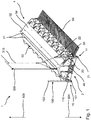
- FIG. 1 - 12 an exemplary embodiment of a poultry housing device according to the invention is shown.
- the poultry accommodation device 1 extends in the longitudinal direction from a first end 2 to a second end 4.
- Laying nests 30-37 are arranged next to one another along the longitudinal direction.
- Two adjacent laying nests 30 - 37 are each separated from one another by a partition 38.
- the poultry accommodation device 1 has a first corner 10 and a second corner 11 in the area of the first end 2.
- a first support element 100 is arranged at the first corner 10.
- the first support element 100 extends in a vertical direction, perpendicular to the longitudinal direction of the poultry housing device, from a first lower standing end 101 to a first upper free end 102.
- the first support element 100 has a substantially quadrangular cross section.
- a first guide device 110 is arranged at the first corner 10.
- the first guide device 110 forms a square through opening in which the first support element 100 is arranged and is guided for a vertical displacement movement relative to the guide device.
- the first support element 100 has an outer circumferential surface which is designed to correspond to an inner circumferential surface of the through opening of the first guide device 110.
- the first support element 100 has a multiplicity of cutouts 126.
- the recesses are arranged in a row next to one another in the vertical direction.
- the poultry accommodation device 1 has a first locking element designed as a first pawl 120, the blade 120 being arranged and designed in such a way that it can snap into one of the recesses 126 with a snap-in projection 120a.
- the pawl 120 and the recesses 126 are designed such that a movement of the support element 100 in an upward vertical standing direction 500 by engaging the latching projection of the pawl into a recess is blocked, whereas a movement in a downward vertical freewheeling direction 501 opposite to this is enabled.
- the pawl 120 is arranged rotatably about a first pivot point 122, which is arranged above the latching projection 120a and laterally next to the support element.
- a spring element 124 is arranged and designed in such a way that it exerts a spring force on the pawl 120, so that the pawl is always acted upon by a force which presses the latching projection 120a in the direction of the first support element 100.
- the pawl 120 can thereby pivot about the axis of rotation counter to the spring force of the spring 124 when the support element is moved downwards by its own weight and thereby exerts a force through the recesses on the latching projection.
- the pawl 120 is held in the recess in a self-reinforcing manner when an upward force acts on the support element.
- the support element 100 can therefore indeed be extended downwards, but is blocked against being retracted upwards by the pawl 120.
- the weight of the first support element 100, the friction of the first support element 100 within the first guide device 110 and the spring force of the spring 124 with which the pawl 120 is pressed into the recesses 126 are coordinated to the extent that, on the one hand, the spring 124 and the pawl 120 presses with sufficient force into the recesses 126 and thus fulfills its latching function and, on the other hand, enables the first support element 100 to move in the freewheeling direction 501 as soon as the support element 100 is unloaded by pushing the pawl out of the recess.
- the pawl can lock positively in the recess under the action of the weight of the poultry accommodation device on the support element and thereby prevent the pawl from moving out of the recess in an undesired manner.
- the poultry accommodation device 1 also has an unlocking element 121a which engages an eyelet 121 fastened to the pawl 120 in order to move the pawl 120 against the spring force.
- the pawl 120 is not located in one of the recesses 126 and is not locked into place.
- the unlocking element 121a is actuated, the poultry holding device 1 can be moved in the freewheeling direction 501 and can thus be lowered.
- the disengagement of the pawl 120 from one of the recesses 126 can be supported by means of a stand relief element, since the disengagement of the pawl 120 from one of the recesses 126 is simplified when the support element 100 is unloaded.
- the stand relief element can be designed, for example, as a rope or as a Bowden cable.
- Another possible unlocking mechanism 225 is, for example, in FIG Figure 12 shown.
- a second support element 20 is arranged at the second corner 11, which extends from a second lower standing end 21 to a second upper free end 22 and which is arranged analogously to the first guide element 100 in a second guide device 23, at the lower standing end of which a standing element 24 is arranged and which is movable or immovable according to the invention by means of a second locking element embodied as a second pawl 26.
- the poultry accommodation device 1 also has a roof 50 with a ridge from which roof elements extend slopingly.
- Two roof rockers 51 are movably arranged on the ridge and prevent or at least make it more difficult for a poultry animal, in particular a duck, to sit on it.
- a removable cover element 52 is arranged adjacent to each side of the ridge.
- the fixed covering element 54 is arranged in a fixed manner in the operating mode and, in particular, is not intended to be removed in the operating mode.
- a nest roof extension element 58 is also shown, which is arranged in addition to the removable cover element 52 and the fixed cover element 54 and forms the roof 50 of the poultry accommodation device 1.
- the nest roof extension element 58 can be mounted variably with respect to a clear height above the floor surface, so that it can also be used to set a brightness in the laying nest or to cast a shadow in the nest.
- the nest roof extension element 58 is arranged pivotably about a horizontal pivot axis. Furthermore, it is preferred that the horizontal pivot axis is aligned essentially parallel to the longitudinal direction of the poultry accommodation device 1. Furthermore, the pivot axis is preferably arranged adjacent to an inwardly pointing edge of the fixed covering element 54 running in the longitudinal direction of the poultry housing device 1.
- the nest roof extension element 58 can alternatively or additionally be arranged displaceably.
- the nest roof extension element 58 can be arranged and designed to be moved under and / or over the fixed cover element 54 and / or the removable cover element 52.
- the nest roof extension element 58 has a depth in a direction from the ridge to the eaves, and the depth is designed to be variable.
- a plurality of different nest roof extension elements 58 are provided which have different depths and are interchangeable Figure 5 and the Figure 6 shows how a nest access barrier can be implemented.
- a guide recess 56 is arranged on a side wall at the first end 2 of the poultry accommodation device 1 and preferably also on a side wall at the second end 4 of the poultry accommodation device 1 and in the partition walls 38 Guide pin 55 are guided. This enables the nest access barrier to be slidable.
- the nest access barrier can be moved by means of a barrier pulling element 310 in that it extends through the fixed covering element 54 to the nest access barrier.
- the guide pin 55 is arranged in an upper position. In this position, the nest access barrier is in an upper position so that access to the nest is made possible.
- the guide pin is arranged in a lower position. In this position, the nest access barrier is in a lower position, so that access to the nest is essentially not possible.
- the barrier pulling element 310 comprises a first lifting element 312 and a second lifting element 314.
- the poultry housing device is also arranged on a nest lifting device 300 which the poultry housing device 1 can lift.
- the poultry accommodation device is shown in a state in which the support elements 100, 20 are extended.
- the laying nest 30 comprises a tiltable step surface 200.
- the tiltable step surface extends from an outer end, which is located on an outer edge of the poultry accommodation device 1, to an inner end, which is not shown here and extends to an egg conveyor device 40 .
- From the outer end 201 to the inner end of the tiltable tread surface the latter preferably has an incline.
- the slope is sloping from the outer to the inner end. As a result of this sloping inclination, one rolls inside the laying nest 30 on the tiltable tread surface 200 deposited egg in the direction of the center of the poultry accommodation facility, where present, as in Figure 1 shown, the egg conveyor 40 is arranged.
- the angle of inclination of the tiltable step surface 200 can be changed in the present case by means of a gradient adjustment device 210.
- the gradient adjustment device 210 comprises an adjustment rod 212 on which a region of the tiltable tread surface 200 rests adjacent to the outer end 201.
- the adjustment rod 212 can be adjusted in height by means of a locking device 214.
- the locking device 214 comprises a first locking hole 215, a second locking hole 216 and a third locking hole in which the adjusting rod 212 is arranged.
- an edge protection element 7 is also shown. This is intended in particular to be arranged on an edge in order to enable the animals to be protected. If the bridge element is not to be arranged, for example due to the height of the poultry accommodation device 1 or large animals, the edge protection element 7 can protect the edge in such a way that the animals cannot injure themselves on it.
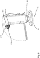
- the locking device is shown with a resiliently mounted pawl 220 with which a freewheel is realized.
- the pawl 220 is mounted rotatably about a pivot point 222.
- the pawl has a latching end 221 which can be arranged in recesses (not shown) in the support element.
- the latching end 221 is spaced from the pivot point 222, so that a force not directed at the pivot point 222 at the latching end 221 results in a torque about the pivot point 222.
- a spring element 224 is arranged, which acts on the pawl 220 at a distance from the pivot point 222, in particular the latching end 221, with a force in the direction of the recesses.
- a disengaging pull 225 which is arranged and designed to move the pawl 220 in such a way that, in particular, the engaging end 221 moves against the spring force, thus causing the pawl 220 to disengage from the recess and the support element in a support direction is movable.
- the disengaging end 223 is also spaced apart from the pivot point 222, so that a force at the disengaging end 223 causes a moment about the pivot point 222.
- the height of the poultry accommodation device 1 can be adjusted with little effort due to the first support element 100 and the second support element 20.
- the adjustment of the height of the poultry accommodation device above a set-up area can be automated and / or brought about by a central control point. As a result, the animals are disturbed less, find constant nest entry conditions despite increasing amounts of litter and are thus kept more species-appropriate by the poultry accommodation device, so that the well-being of the animals can be significantly increased.
- the well-being of the animals can also be increased by the removable cover elements.
- the lighting conditions in the laying nests may be changed, since the angle of incidence of light changes as a result of the height adjustment.
- the removable cover elements 52 and the adjustable nest roof extension element 58 can in turn create the same or similar conditions.
- the rolling angles of eggs within the laying nests can also be changed.
- the constant nest conditions also improve egg removal.
Landscapes
- Life Sciences & Earth Sciences (AREA)
- Environmental Sciences (AREA)
- Birds (AREA)
- Zoology (AREA)
- Animal Husbandry (AREA)
- Biodiversity & Conservation Biology (AREA)
- Animal Behavior & Ethology (AREA)
- Housing For Livestock And Birds (AREA)
Description
- "Die Erfindung betrifft eine Geflügelaufenthaltsvorrichtung, insbesondere zur Eiablage für Geflügeltiere wie Enten oder Hühner, einen Geflügelstall, insbesondere zur Haltung von Geflügeltieren wie Enten oder Hühnern, und ein Verfahren zur Haltung von Geflügeltieren wie Enten oder Hühnern."
- Im Stand der Technik sind Vorrichtungen zur Eiablage für Enten grundsätzlich bekannt. In bekannten Vorrichtungen für Enten sind in der Regel Legenester vorgesehen, in denen eine Ente ein Ei legen kann. Von dem Legenest aus kann das Ei im Anschluss manuell, halbautomatisiert oder automatisiert abtransportiert werden. Ein Nachteil der im Stand der Technik bekannten Vorrichtungen zur Eiablage besteht unter anderem darin, dass die Eier nicht oder lediglich in eingeschränktem Maße aus dem Legenest herausgenommen werden können bzw. nicht oder in eingeschränkter Weise aus dem Legenest automatisiert abtransportiert werden können. Insbesondere können unterschiedliche Faktoren den Eiabtransport verhindern bzw. verschlechtern.
- Darüber hinaus ist es ein Nachteil von bekannten Vorrichtungen, dass die Nester nicht die gewünschten Lichtverhältnisse aufweisen und somit das Wohlbefinden der Tiere und infolgedessen die Produktivität der Eiablage eingeschränkt ist. Darüber hinaus ist es ein besonderer Nachteil der im Stand der Technik bekannten Vorrichtungen, dass die Geflügelaufenthaltsvorrichtungen regelmäßig verschmutzen. Dies geschieht unter anderem dadurch, dass regelmäßig neuer Einstreu in den Stall eingebracht wird und dieser insbesondere mit zunehmender Menge in die Geflügelaufenthaltsvorrichtung gelangt. Unter anderem daher ist eine regelmäßige Reinigung der Geflügelaufenthaltsvorrichtung, die in der Regel manuell und personalaufwendig durchgeführt werden muss, notwendig.
- Darüber hinaus verändern sich durch den Stalleinstreu regelmäßig die Nesteintrittsverhältnisse für die Enten, sodass sich diese ständig an neue Verhältnisse gewöhnen müssen, was wiederum zu einem verminderten Wohlbefinden der Tiere führen kann. Insbesondere Enten können sich an derartige veränderte Bedingungen nur langsam gewöhnen. Darüber hinaus verschmutzt ein derartiger Stall nach der Reinigung schnell wieder. Ferner ist es ein Nachteil der im Stand der Technik bekannten Vorrichtungen, dass die Enten nachts in den Legenestern verweilen können und diese dadurch beschmutzen. Die Haltung von Enten wird infolgedessen teuer und insbesondere vor dem Hintergrund steigender Anforderungen an das Wohlbefinden der Tiere ungeeignet. Neben den grundsätzlich bestehenden Anforderungen an das Wohlbefinden der Tiere resultiert dieses geringe Wohlbefinden ferner in einer eingeschränkten Produktivität der Tiere bei der Eierproduktion.
- Aus
EP2829745A1 ist eine Stallkonstruktion für die Aufzucht von Geflügel bekannt, die über Legenester und einen Rahmen verfügt. An dem Rahmen sind Stützbeine angeordnet, die eine Höhenjustierung zum Ausgleich von Bodenunebenheiten ermöglicht. Nach Ausgleich der Bodenunebeneinheiten werden die Stützbeine durch eine Klemmung mittels Reibschluss und zusätzlich eine Verschraubung mittels Formschluss gesichert.US3124102A undEP2907381A1 zeigen ebenfalls Stallkonstruktionen mit solchen ausfahrbahren und in einer Position sicherbaren Stützbeinen. - Neben den allgemeinen Anforderungen an die Entenhaltung, wie beispielsweise der Stallsauberkeit, dem Wohlbefinden der Tiere sowie geringer Kosten und hoher Produktivität, ist es daher eine Aufgabe der vorliegenden Erfindung, eine Geflügelaufenthaltsvorrichtung zur Eiablage für Enten, einen Geflügelstall zur Haltung von Enten und ein Verfahren zur Haltung von Enten bereitzustellen, welche gleichbleibende Nestverhältnisse ermöglicht.
- Gemäß einem ersten Aspekt der vorliegenden Erfindung wird die eingangs genannte Aufgabe gelöst durch eine Geflügelaufenthaltsvorrichtung nach Anspruch 1, insbesondere zur Eiablage für Enten, mit einer Mehrzahl von nebeneinander angeordneten Legenestern, die oberhalb einer Bodenfläche angeordnet sind, mindestens einem Stützelement, das sich in vertikaler Richtung von einem unteren Standende zu einem oberen Freiende erstreckt und in vertikaler Richtung relativ bewegbar zu der Bodenfläche angeordnet ist, und mit einem Verriegelungselement, welches mit dem Stützelement zusammenwirkt, um eine Bewegung des Stützelements in einer vertikal nach oben gerichteten Standrichtung relativ zu der Bodenfläche zu sperren und eine Bewegung des Stützelements relativ zu der Bodenfläche in einer vertikal nach unten gerichteten Freilaufrichtung freizugeben.
- Der Erfindung liegt unter anderem die Erkenntnis zugrunde, dass die Produktivität bei der Enteneierproduktion stärker durch das Wohlbefinden der Tiere beeinflusst wird als bei anderen Eier-legenden Tierarten. Darüber hinaus wurde erkannt, dass das Wohlbefinden der Enten dadurch positiv beeinflusst wird, dass diese gleichbleibende Nestverhältnisse vorfinden. Durch die regelmäßige Einbringung von Einstreu wächst jedoch die Höhe des Einstreus im Stall regelmäßig an, sodass sich die Nesteintrittsverhältnisse in der Regel verändern. Die ständige Beseitigung des alten Einstreus vor der Einbringung des neuen Einstreus ist bereits aus wirtschaftlichen Gründen keine Möglichkeit, da der Personalaufwand zu hoch wäre. Ferner ist diese Möglichkeit aus verhaltenstechnischen Gründen in der Regel nicht möglich, da die Tiere durch die regelmäßige Anwesenheit von Menschen in ihrem Wohlbefinden gestört werden.
- Die erfindungsgemäße Geflügelaufenthaltsvorrichtung kann mit geringstem manuellen Aufwand oder auch automatisiert an unterschiedliche Einstreuhöhen im Stall angepasst werden, indem das mindestens eine Stützelement bei Anhebung der Geflügelaufenthaltsvorrichtung, beispielsweise durch sein Eigengewicht, ausfährt. Somit kann die Höhe der Bodenfläche und der Geflügelaufenthaltsvorrichtung oberhalb einer Aufstellfläche, auf der die Stützelemente mit dem Standende aufstehen, verändert werden und daher der Abstand der Bodenfläche zu einem auf der Aufstellfläche anwachsenden Einstreuhaufen konstant gehalten werden. Infolgedessen ist auch der Verschmutzungsgrad innerhalb der Geflügelaufenthaltsvorrichtung kontrollierbar und das Wohlbefinden der Tiere kann weiter gesteigert werden.
- Im Betriebsmodus ist die Bodenfläche vorzugsweise im Wesentlichen horizontal ausgerichtet. Die Bodenfläche kann als eine durchgängige Fläche oder durch zwei oder mehrere einzelne Bodenflächenelemente ausgebildet werden. Die Bodenfläche erstreckt sich in Längsrichtung und Breitenrichtung vorzugsweise von den jeweils gegenüberliegenden Endseiten der Geflügelaufenthaltsvorrichtung.
- In einer bevorzugten Fortbildung ist vorgesehen, dass die Geflügelaufenthaltsvorrichtung ein Rahmengestell aufweist. Das Rahmengestell weist vorzugsweise zwei parallele Rahmenelemente in Längsrichtung der Geflügelaufenthaltsvorrichtung und zwei parallele Rahmenelemente in Breitenrichtung auf. Die Bodenfläche kann beispielsweise an dem Rahmengestell befestigt sein. Das Rahmengestell kann Quer- und/oder Längsstreben aufweisen, die die Stabilität der Geflügelaufenthaltsvorrichtung verbessern und an denen die Legenester angeordnet sein können. Die Rahmenelemente des Rahmengestells bestehen vorzugsweise aus Stahl, und/oder Aluminium, und/oder Kunststoff..
- Die einzelnen Legenester umfassen vorzugsweise jeweils eine erste Seitenwand und eine zweite Seitenwand. Die erste Seitenwand und die zweite Seitenwand sind vorzugsweise flächenparallel ausgerichtet. Ferner sind die erste Seitenwand und die zweite Seitenwand vorzugsweise senkrecht zu der Bodenfläche angeordnet. Die erste und die zweite Seitenwand erstrecken sich vorzugsweise parallel zur Breitenrichtung der Geflügelaufenthaltsvorrichtung. Insbesondere ist es bevorzugt, dass die Legenester jeweils durch Seitenwände seitlich begrenzt werden und dass zwischen einem ersten Legenest und einem zweiten Legenest die Seitenwand durch eine Trennwand gebildet wird. Darüber hinaus ist es bevorzugt, dass die Legenester entlang der Längsrichtung der Geflügelaufenthaltsvorrichtung nebeneinander angeordnet sind. Darüber hinaus ist es bevorzugt, dass die Geflügelaufenthaltsvorrichtung ein Dachelement aufweist, das die Legenester teilweise oder im Wesentlichen vollständig überdeckt.
- Die in Längsrichtung nebeneinander angeordneten Legenester können somit auch eine Legenestreihe bilden. Darüber hinaus kann es bevorzugt sein, dass die Geflügelaufenthaltsvorrichtung eine erste Legenestreihe und eine zweite Legenestreihe aufweist. Insbesondere ist es bevorzugt, dass die erste Legenestreihe und die zweite Legenestreihe in Breitenrichtung voneinander beabstandet sind, und/oder zwischen der ersten Legenestreihe und der zweiten Legenestreihe eine Eiertransportvorrichtung angeordnet ist. Darüber hinaus kann es bevorzugt sein, dass die erste Legenestreihe die gleiche Anzahl an Legenestern aufweist wie die zweite Legenestreihe, und/oder die erste Legenestreihe und die zweite Legenestreihe in Längsrichtung die gleiche Abmessung aufweisen. Ferner kann es bevorzugt sein, dass zwischen der ersten Legenestreihe und der zweiten Legenestreihe im Wesentlichen kein Abstand vorhanden ist. Darüber hinaus kann es bevorzugt sein, dass die Bodenfläche eine oder mehrere Durchtrittsöffnungen aufweist, sodass gelegte Eier von der Bodenfläche in einen Bereich unterhalb der Legenester gelangen und von hier aus abtransportiert werden können. Eine hierzu unterhalb oder fluchtend zu der Bodenfläche vorgesehene Eiertransportvorrichtung kann manuell oder motorisch, beispielsweise mittels eines elektrischen Antriebs, angetrieben sein.
- Vorzugsweise weist das mindestens eine Stützelement ein derartiges Eigengewicht auf, dass das Stützelement bei Nichtbelastung durch die Geflügelaufenthaltsvorrichtung, also wenn das Standende unbelastet ist, durch das Eigengewicht ausfährt, insbesondere unter seinem Eigengewicht auch gegen einen mechanischen Widerstand der Sperreinrichtung ausfährt. Ferner ist es bevorzugt, dass das untere Standende des Stützelementes an der Aufstellfläche befestigt ist.
- Das mindestens eine Stützelement erstreckt sich in vertikaler Richtung von dem unteren Standende zu dem oberen Freiende. Als Erstreckungsrichtung des Stützelements in vertikaler Richtung wird auch verstanden, dass eine Richtungskomponente der Erstreckungsrichtung in vertikaler Richtung verläuft. Das Stützelement kann also beispielsweise auch schräg angeordnet werden, so dass die Erstreckungsrichtung zwischen dem unteren Standende und dem oberen Freiende eine vertikale Richtungskomponente und eine horizontale Richtungskomponente aufweist.
- Vorzugsweise weist das Stützelement einen Querschnitt auf, der dreieckig, viereckig und/oder polygonal ausgebildet ist. Darüber hinaus kann der Querschnitt auch rund, mit einem runden Umfangsabschnitt und/oder elliptisch ausgebildet sein. Darüber hinaus ist es bevorzugt, dass der Querschnitt eine langgezogene rechteckige Ausbildung aufweist, sodass das Stützelement plattenförmig ausgebildet ist. Vorzugsweise ist das Stützelement an der Geflügelaufenthaltsvorrichtung derart angeordnet, dass dessen Erstreckungsrichtung oder eine Richtungskomponente der Erstreckungsrichtung im Wesentlichen parallel zu einer Flächennormalen der Bodenfläche ausgerichtet ist.
- Ferner ist es bevorzugt, dass die Geflügelaufenthaltsvorrichtung zwei oder mehrere Stützelemente aufweist. Das mindestens eine Stützelement ist ferner bewegbar angeordnet. Beispielsweise kann die Geflügelaufenthaltsvorrichtung eine Führungseinrichtung aufweisen, in der das Stützelement entlang seiner Erstreckungsrichtung geführt ist. Insbesondere ist es bevorzugt, dass die Führungsvorrichtung rohrförmig ausgebildet ist.
- Durch die bewegbare Anordnung des mindestens einen Stützelements weist dieses mindestens eine Bewegungsrichtung auf. Zumindest eine Richtungskomponente dieser Bewegungsrichtung ist im Betriebsmodus vertikal ausgerichtet. Das heißt insbesondere, dass das Stützelement von der Geflügelaufenthaltsvorrichtung in Richtung der Aufstellfläche ausfahrbar ist. Infolgedessen kann das untere Standende des Stützelements von der Bodenfläche weg bewegt werden, sodass der Abstand zwischen dem unteren Standende und den Legenestern und/oder der Bodenfläche veränderbar, insbesondere vergrößerbar, ist. Infolgedessen kann der Abstand zwischen den oberhalb der Bodenfläche angeordneten Legenestern und der Aufstellfläche vergrößert werden. Vorzugsweise ist die Bewegungsrichtung parallel zu einer Flächennormalen der Bodenfläche ausgerichtet.
- Das untere Standende des Stützelements ist im Betriebsmodus der Aufstellfläche, wie einem Stallboden, zugewandt, auf der die Geflügelaufenthaltsvorrichtung aufgestellt ist. Das obere Freiende ist in Bezug auf das untere Standende der Aufstellfläche abgewandt. Das mindestens eine Stützelement ist in seiner Erstreckungsrichtung ferner derart angeordnet und ausgebildet, dass dieses in der Standrichtung von dem unteren Standende zu dem oberen Freiende im Wesentlichen durch eine vorzugsweise lösbare Arretierung unbewegbar ist. Das bedeutet, sobald eine Kraft am unteren Standende in Richtung des oberen Freiendes angreift, dass das Stützelement durch diese Kraft im Wesentlichen nicht bewegt wird. Das Stützelement ist beispielsweise derart eingerastet, dass dieses in der Standrichtung nicht bewegbar ist.
- Darüber hinaus ist das Stützelement derart angeordnet und ausgebildet, dass dieses in der Freilaufrichtung bewegbar ist. Wenn demnach eine Kraft an dem Stützelement von dem oberen Freiende in Richtung des unteren Standendes angreift, wird das Stützelement in seiner Erstreckungsrichtung bewegt. Dadurch kann das Stützelement durch das Angreifen einer Kraft in Freilaufrichtung ausgefahren werden. Vorzugsweise ist das Stützelement in seiner Erstreckungsrichtung derart angeordnet und ausgebildet, dass die Gewichtskraft des Stützelements ausreicht, um eine Bewegung in Freilaufrichtung zu ermöglichen, sobald keine Kraft in Standrichtung wirkt bzw. eine Kraft in Freilaufrichtung, beispielsweise durch das Eigengewicht, größer ist als eine Kraft in Standrichtung, beispielsweise durch eine Reibkraft. Eine Realisierung eines im Vorherigen beschriebenen Stützelements erfolgt durch einen Freilauf, insbesondere einen Linearfreilauf. Das Stützelement besteht vorzugsweise aus Stahl oder umfasst diesen. Ferner vorzugsweise besteht das Stützelement aus Aluminium oder Kunststoff oder umfasst diesen bzw. diese.
- Der Freilauf sperrt also ein Einfahren des Stützelements in Standrichtung und ermöglicht ein Ausfahren des Stützelements in Freilaufrichtung. Hierdurch kann die Höhe der Bodenfläche und der Legenester oberhalb einer Aufstellfläche, auf der die Geflügelaufenthaltsvorrichtung aufgestellt ist, einem wachsenden Einstreuhaufen unterhalb und/oder neben der Geflügelaufenthaltsvorrichtung angepasst werden. Die Sperrwirkung des Freilaufs gegen Einfahren ist vorzugsweise lösbar, um nach Entfernen des gewachsenen Einstreuhaufens die Geflügelaufenthaltsvorrichtung wieder absenken zu können. Die Sperrwirkung kann aber auch unlösbar sein, in diesem Falle können die Stützelemente so ausgebildet sein, dass sie nach unten aus ihrer Führungsvorrichtung herausgezogen werden können und dann von oben wieder in ihre Führungsvorrichtung eingesetzt werden zu können, um nach einem vollständig ausgefahrenen Zustand einen vollständig eingefahrenen Zustand zu erreichen.
- Vorzugsweise ist die Geflügelaufenthaltsvorrichtung gekennzeichnet durch eine sich entlang einer Seite im Bereich der Bodenfläche erstreckende Seitenschiene, die eine oder mehrere Aussparungen im Bereich der Legenester aufweist. Seitenschienen werden insbesondere in Geflügelaufenthaltsvorrichtungen für Hühnervögel vorgesehen, wobei ein Hühnervogel zum Eintreten in die Geflügelaufenthaltsvorrichtung zunächst auf die Seitenschiene und abschließend hinab in das Legenest zu steigen hat. Eine durch eine ausgesparte Seitenschiene gekennzeichnete Geflügelaufenthaltsvorrichtung weist insbesondere den Vorteil auf, dass der Nesteintritt für Enten vereinfacht ist. Dies liegt insbesondere in der anatomischen Ausführung der Entenfüße begründet, da diese besonderes breit ausgebildet sind.
- Durch die erfindungsgemäße Geflügelaufenthaltsvorrichtung können konstante Nesteintrittsverhältnisse auch bei kontinuierlichem Einbringen von Einstreu in einen Stall ermöglicht werden. Beispielsweise kann die Geflügelaufenthaltsvorrichtung an einer Nesthebevorrichtung angeordnet werden, die die Geflügelaufenthaltsvorrichtung in vertikaler Richtung anhebt. Durch dieses Anheben wird ein Ausfahren der Stützelemente ermöglicht, beispielsweise kann bei entsprechender Ausbildung der Anordnung des Stützelements und entsprechendem Gewicht des Stützelements das Stützelement automatisch ausgefahren. Dies wird durch die bewegbare Anordnung des Stützelements in Freilaufrichtung ermöglicht. Nachdem die Geflügelaufenthaltsvorrichtung in die gewünschte Position bzw. Höhe über der Aufstellfläche gebracht wurde, kann beispielsweise die Nesthebevorrichtung wieder kraftlos geschaltet werden und die Geflügelaufenthaltsvorrichtung stützt sich auf dem mindestens einen Stützelement ab, da dieses in Standrichtung im Wesentlichen unbewegbar angeordnet ist. Somit kann innerhalb von kürzester Zeit die Höhe der Geflügelaufenthaltsvorrichtung über der Aufstellfläche angepasst und ein stabiler Stand erreicht werden. Darüber hinaus kann eine Vielzahl von Geflügelaufenthaltsvorrichtungen innerhalb kürzester Zeit in ihrer Höhe verstellt werden. Wie im Folgenden noch näher erläutert wird, ist in einer bevorzugten Ausführungsvariante auch eine Absenkung der Geflügelaufenthaltsvorrichtung durch ein Entsperrelement möglich.
- Es ist darüber hinaus vorteilhaft, dass zur Einstellung der Höhe kein Bediener den Stall betreten muss. Dies spart Personalkosten und Personalaufwand, aber resultiert ferner in einer Verbesserung des Wohlbefindens der Tiere. Durch den Eintritt eines Bedieners in den Stall werden die Tiere, insbesondere Enten, gestört, was in Stress resultieren kann. Darüber hinaus müssen die Geflügelaufenthaltsvorrichtungen seltener gereinigt werden, sodass auch hier eine Reduktion von Personalkosten und -aufwänden resultiert und das Wohlbefinden der Tiere noch weiter gesteigert wird.
- Die hochziehbare Geflügelaufenthaltsvorrichtung hat den weiteren Vorteil, dass die eine oder auch mehrere Geflügelaufenthaltsvorrichtungen mit geringem Aufwand so weit hochgezogen werden können, dass die Stützelemente maximal ausgefahren sind oder sogar von der Aufstellfläche abgehoben werden und dieser angehobenen Position der Geflügelaufenthaltsvorrichtungen der Stall ohne großen Aufwand gereinigt werden kann.
- In einer bevorzugten Ausführungsvariante der Geflügelaufenthaltsvorrichtung ist vorgesehen, dass die Bodenfläche durch eine Gitter- und/oder Streben- und/oder Gestellanordnung ausgebildet ist und eine drei- oder mehreckige Geometrie aufweist, wobei vorzugsweise in einem Bereich angrenzend an eine erste Ecke ein erstes Stützelement, und/oder an eine zweite Ecke ein zweites Stützelement, und/oder an eine dritte Ecke ein drittes Stützelement, und/oder an eine vierte Ecke ein viertes Stützelement angeordnet ist.
- Die Stützelemente können vorzugsweise auch vollständig oder teilweise direkt an den Ecken angeordnet sein. Darüber hinaus können die Stützelemente auch im Bereich von Kanten angeordnet sein. Insbesondere ist es bevorzugt, dass die Stützelemente an Kanten angeordnet sind, die sich zwischen der ersten, und/oder zweiten, und/oder dritten und/oder vierten Ecke erstrecken. Ferner besteht die Möglichkeit, dass die Stützelemente unter der Bodenfläche angeordnet sind. Ferner ist es bevorzugt, dass das mindestens eine Stützelement parallel zu einer Flächennormalen der Bodenfläche bewegbar ist. Ferner vorzugsweise ist die Erstreckungsrichtung des mindestens einen Stützelements parallel zu einer Flächennormalen der Bodenfläche des Gestells ausgerichtet.
- Gemäß einer weiteren bevorzugten Ausführungsvariante der Geflügelaufenthaltsvorrichtung ist vorgesehen, dass das mindestens eine Stützelement mittels einer Sperreinrichtung gegen eine Bewegung entlang seiner Erstreckungsrichtung gehalten ist, wobei die Sperreinrichtung vorzugsweise mindestens eine federnd gelagerte Klinke, insbesondere einen Linearfreilauf, und/oder mindestens ein bewegbares Schnappelement, und/oder mindestens einen Reibwiderstand, und/oder mindestens eine Hydraulikvorrichtung, und/oder eine Bremsvorrichtung, vorzugsweise umfassend Bremsbacken, umfasst.
- Bei mindestens einer federnd gelagerten Klinke, weist das Stützelement vorzugsweise korrespondierend zur Klinke ausgebildete Ausnehmungen auf. Die Klinke und die Ausnehmungen sind vorzugsweise derart ausgebildet, dass die Unbeweglichkeit in Standrichtung und die Beweglichkeit in Freilaufrichtung des Stützelements gewährleistet ist. Auch bei dem mindestens einen bewegbaren Schnappelement ist es bevorzugt, dass das Stützelement korrespondierend ausgebildete Ausnehmungen aufweist, so dass das Stützelement in Standrichtung im Wesentlichen unbeweglich ist und in Freilaufrichtung bewegbar. Alternativ zu den zuvor genannten Ausnehmungen können auch Verdickungen, Wölbungen oder anordenbare Elemente an dem Stützelement angeordnet werden. Alternativ kann auch ein Reibwiderstand vorgesehen werden, um die Unbeweglichkeit des Stützelements in Standrichtung und die Beweglichkeit des Stützelements in Freilaufrichtung zu ermöglichen. Beispielsweise kann die Sperreinrichtung mit dem Stützelement eine Reibflächenpaarung bilden, wobei ein Reibkoeffizient in Bewegungsrichtung des Stützelements anisotrop ausgebildet ist. Somit kann beispielsweise ein Reibwiderstand zwischen der Sperreinrichtung und dem Stützelement in Standrichtung hoch und in Freilaufrichtung niedrig ausgebildet werden. Infolgedessen kann die Beweglichkeit in Freilaufrichtung und die Unbeweglichkeit in Standrichtung realisiert werden. Durch die Bremsbacken wird vorzugsweise aufgrund einer winkligen Zwangsführung eine Klemmung des Stützelementes ermöglicht, wobei diese Klemmung lediglich in Standrichtung erfolgt und nicht in Freilaufrichtung. Bei dem Einsatz der Hydraulikvorrichtung ist es insbesondere bevorzugt, dass die Verstellung des Stützelementes stufenlos erfolgt. Bei den im Vorherigen beschriebenen Ausführungsvarianten für die Sperreinrichtung ist es besonders bevorzugt, dass diese jeweils eine Entsperreinrichtung umfasst, mittels derer eine Bewegung des Stützelements in Standrichtung ermöglicht wird.
- Diese Ausführungsvariante der Geflügelaufenthaltsvorrichtung hat den besonderen Vorteil, dass das Stützelement in sicherer Weise bewegbar in Freilaufrichtung und im Wesentlichen unbewegbar in Standrichtung angeordnet werden kann. Insbesondere besteht hiermit die Möglichkeit, eine sichere und robuste Realisierung der Geflügelaufenthaltsvorrichtung zu gewährleisten. Ferner können geringe Produktionskosten realisiert werden.
- Eine weitere bevorzugte Fortbildung der Geflügelaufenthaltsvorrichtung zeichnet sich dadurch aus, dass diese eine Führungsvorrichtung für das mindestens eine Stützelement umfasst, wobei die Führungsvorrichtung insbesondere eine rohrförmige Geometrie mit einem Innenquerschnitt aufweist, das mindestens eine Stützelement einen Außenquerschnitt aufweist, wobei der Innenquerschnitt der Führungsvorrichtung und der Außenquerschnitt des Stützelements insbesondere die gleiche Geometrie aufweisen und der Innenquerschnitt der Führungsvorrichtung und der Außenquerschnitt des Stützelements insbesondere derart ausgebildet sind, dass das mindestens eine Stützelement bewegbar innerhalb der Führungsvorrichtung anordenbar ist. Eine derartige Führung des Stützelements mittels einer Führungsvorrichtung ermöglicht das sichere Bewegen der Geflügelaufenthaltsvorrichtung. Insbesondere besteht mit einer derartigen Führung die Möglichkeit, dass die Geflügelaufenthaltsvorrichtung mittels einer labilen Nesthebevorrichtung angehoben werden kann und dennoch im Anschluss ein sicherer Stand gewährleistet werden kann, da die Nesthebevorrichtung entlastet werden kann und keine dauerhaften Kräfte aufnehmen muss, die stattdessen durch das mindestens eine geführte Stützelement aufgenommen werden. Somit besteht die Möglichkeit einer einfachen und kostengünstigen Anhebung der Geflügelaufenthaltsvorrichtung. Vorzugsweise ist für jedes Stützelement eine Führungsvorrichtung angeordnet.
- Ferner ist vorzugsweise vorgesehen, dass das mindestens eine Stützelement an mindestens einer Außenseite Aussparungen aufweist, die mindestens eine federnd gelagerte Klinke ein von einem Drehpunkt beabstandetes Einrastende aufweist, wobei das Einrastende in den Aussparungen anordenbar ist, und vorzugsweise durch eine Feder in Richtung der Aussparungen mit einer Kraft beaufschlagt ist, und die Aussparungen und die Klinke derart angeordnet und ausgebildet sind, dass das mindestens eine Stützelement in Standrichtung im Wesentlichen nicht bewegbar ist, wobei das Einrastende bei Bewegung des mindestens einen Stützelements in Standrichtung in einer Aussparung einrastet, und das mindestens eine Stützelement in Freilaufrichtung bewegbar ist, wobei das Einrastende bei Bewegung des mindestens einen Stützelements in Freilaufrichtung nicht in einer Aussparung einrastet.
- Eine Kombination einer Klinke mit korrespondierend ausgebildeten Ausnehmungen resultiert in dem Vorteil einer einfachen und robusten Sperreinrichtung, die einfach zu warten ist und darüber hinaus eine geringe Ausfallwahrscheinlichkeit bietet. Darüber hinaus sind die Herstellkosten einer derartigen Geflügelaufenthaltsvorrichtung gering. Insbesondere ist es bevorzugt, dass die Feder eine derartige Federkraft aufweist, dass das Stützelement durch sein Eigengewicht in Freilaufrichtung bei Nichtbelastung durch die Geflügelaufenthaltsvorrichtung die Klinke aus einer eingerasteten Position wegbewegen kann und dann in Freilaufrichtung ausfahren kann.
- In einer weiteren bevorzugten Fortbildung der Geflügelaufenthaltsvorrichtung umfasst diese ein Entsperrelement, das angeordnet und ausgebildet ist, eine Bewegung des mindestens einen Stützelements in Standrichtung zu ermöglichen. Dabei ist es insbesondere bevorzugt, dass das Entsperrelement an der federnd gelagert Klinke angreift und angeordnet und ausgebildet ist, das Einrastende von dem Stützelement zu beabstanden.
- Eine weitere bevorzugte Ausführungsvariante der Geflügelaufenthaltsvorrichtung sieht vor, dass in einem Standmodus das untere Standende des mindestens einen Stützelements auf einer Aufstellfläche angeordnet ist, das Gewicht der Geflügelaufenthaltsvorrichtung zumindest teilweise auf dem mindestens einen Stützelement lastet und das mindestens eine Stützelement die Geflügelaufenthaltsvorrichtung mit einem definierten Abstand über der Aufstellfläche abstützt, und in einem Einstellmodus das Gewicht der Geflügelaufenthaltsvorrichtung im Wesentlichen nicht auf dem mindestens einen Stützelement lastet und das mindestens eine Stützelement in Freilaufrichtung im Wesentlichen durch Eigengewicht bewegbar angeordnet ist. In dem Einstellmodus kann das Gewicht der Geflügelaufenthaltsvorrichtung durch eine Haltevorrichtung gehalten werden, die beispielsweise mittels eines Seils an der Geflügelaufenthaltsvorrichtung realisiert ist. Dadurch wird das oder die Stützelemente entlastet, und bei Anheben der Geflügelaufenthaltsvorrichtung wird das Stützelement, beispielsweise durch sein Eigengewicht, ausgefahren, sodass das untere Standende im Wesentlichen auf einer Aufstellfläche verbleibt bzw. sich durch Eigengewicht wieder zu der Aufstellfläche hin bewegt. Sobald die Gewichtskraft der Geflügelaufenthaltsvorrichtung wieder auf dem Stützelement lastet, stützt sich die Geflügelaufenthaltsvorrichtung mit einem durch den Ausfahrzustand des(der Stützenelemente definierten Abstand über der Aufstellfläche alleinig über das/die Stützenelemente ab.
- In einer weiteren bevorzugten Ausführungsvariante der Geflügelaufenthaltsvorrichtung ist vorgesehen, dass diese ein Entsperrelement umfasst, das angeordnet und ausgebildet ist, eine Bewegung des mindestens einen Stützelements in Standrichtung zu ermöglichen. Durch das Entsperrelement wird die Bewegung des mindestens einen Stützelements in Standrichtung ermöglicht, wodurch der Abstand der Geflügelaufenthaltsvorrichtung zu einer Aufstellfläche reduziert werden kann. Nachdem beispielsweise ein Stall von Einstreu befreit wurde, können somit die Geflügelaufenthaltsvorrichtungen einzeln oder bei der Anordnung mehrerer Geflügelaufenthaltsvorrichtungen auch gemeinsam wieder abgesenkt werden. Das Entsperrelement kann hierbei insbesondere mit einer Sperreinrichtung der zuvor beschriebenen Art zusammenwirken und die Sperrwirkung durch Aufheben einer Bremsoder Rastwirkung aufheben. Bei dem Einsatz mindestens einer federnd gelagerten Klinke oder anderen, durch eine Zustellbewegung auf die das Stützelement wirkenden Sperreinrichtungen kann das Entsperrelement beispielsweise als Seilzugsystem ausgebildet sein. Das Entsperrelement kann ausgebildet sein, um das Einrasten der Klinke zu verhindern oder um eine eingerastete Klinke aus der Einrastung zu lösen. Das Entsperrelement kann mittels einer Handwinde oder motorisch betrieben sein. Insbesondere können mehrere Sperreinrichtungen, beispielsweise mehrere Klinken, durch eine einzige, zentrale Handwinde oder einen einzigen zentralen Motor entsperrt werden. Insbesondere ist es bevorzugt, dass die Sperreinrichtung mindestens eine federnd gelagerte Klinke umfasst, und das Entsperrelement angeordnet und ausgebildet ist, ein Ausrasten der Klinke aus der Aussparung zu bewirken, wobei das Ausrasten vorzugsweise zentral, beispielsweise über einen Zugmechanismus, auslösbar ist.
- Gemäß einer weiteren bevorzugten Ausführungsvariante der Geflügelaufenthaltsvorrichtung ist vorgesehen, dass diese ein Brückenelement umfasst, das angeordnet und ausgebildet ist, einem Geflügeltier, insbesondere einer Ente, den Zugang zu der Bodenfläche zu ermöglichen, wobei das Brückenelement vorzugsweise eine flächige und/oder gestufte Oberfläche aufweist und sich ferner vorzugsweise von einer Kante der Geflügelaufenthaltsvorrichtung ausgehend nach schräg unten erstreckt. Vorzugsweise erstreckt sich das Brückenelement parallel zur Längsrichtung der Geflügelaufenthaltsvorrichtung. Vorzugsweise ist das Brückenelement als Lochblech ausgebildet. Darüber hinaus ist es bevorzugt, dass das Brückenelement aus einem Kunststoff besteht oder diesen umfasst und/oder eine maschenförmige und/oder gelochte Oberfläche aufweist. Ferner ist es bevorzugt, dass die Stege der maschenförmigen Oberfläche abgerundet sind, sodass sich die Tiere, insbesondere die Enten, nicht hieran schneiden können. Ferner vorzugsweise ist das Brückenelement demontierbar und/oder weist eine Einhängvorrichtung auf. Das Brückenelement kann insbesondere um eine horizontale Achse schwenkbar an der Geflügelaufenthaltsvorrichtung befestigt sein, um hierdurch einer Hebe- und Senkbewegung der Geflügelaufenthaltsvorrichtung folgen zu können, ohne dass ein auf der Aufstellfläche aufliegendes Ende des Brückenelements von der Aufstellfläche abhebt.
- Eine weitere bevorzugte Fortbildung der Geflügelaufenthaltsvorrichtung zeichnet sich dadurch aus, dass diese ein Überdeckungselement umfasst, wobei das Überdeckungselement im Betriebsmodus zumindest abschnittsweise in vertikaler Richtung über der Bodenfläche angeordnet ist und vorzugsweise zwischen dem Überdeckungselement und der Bodenfläche eine lichte Höhe durch eine bewegbare Anordnung des Überdeckungselements veränderbar ist, wobei die lichte Höhe insbesondere in einem Nesteingangsbereich veränderbar ist. Vorzugsweise umfasst das Überdeckungselement bewegbare und nicht bewegbare Abschnitte. Insbesondere ist es bevorzugt, dass bewegbare Überdeckungselemente über den Nesteingangsbereichen angeordnet sind.
- Es ist ferner bevorzugt, dass an einer Seite des mindestens einen Legenests eine Eiersammelvorrichtung angeordnet ist, wobei Legeabschnitte der Legenester in vertikaler Richtung von der Eiersammelvorrichtung beabstandet sind, wobei ein Gefälle von dem Legeabschnitt zu der Eiersammelvorrichtung einstellbar ausgebildet ist. Insbesondere ist es bevorzugt, dass die Legenester jeweils zumindest abschnittsweise als ein um mindestens eine horizontale Achse kippbares Element ausgebildet sind. Insbesondere ist es bevorzugt, dass der Legeabschnitt auf bzw. an dem kippbaren Element angeordnet ist bzw. dieses ausbildet. Durch ein kippbares Element als Legeabschnitt kann der Legeabschnitt mit einem Winkel zu einer horizontalen Fläche angeordnet werden. Durch ein derartiges Gefälle kann ein gelegtes Ei schwerkraftbedingt aus dem Legenest in Richtung der Eiersammelvorrichtung abrollen. Insbesondere ist es bevorzugt, dass dieses Gefälle mit einem Winkel von kleiner 7°, 8°, 9° oder 10° und größer als 5°, 6° 7° oder 8°ausgebildet ist. Ein derartig einstellbares kippbares Element hat den besonderen Vorteil, dass die Geflügelaufenthaltsvorrichtung an die individuellen Bedürfnisse der Tiere angepasst werden kann. Insbesondere besteht somit eine Möglichkeit an die Anpassung der Größe der Tiere und/oder der gelegten Eier.
- In einer weiteren bevorzugten Fortbildung der Geflügelaufenthaltsvorrichtung ist vorgesehen, dass diese eine Nestzugangsbarriere umfasst, die angeordnet und ausgebildet ist, um den Zugang zu mindestens einem der Legenester für die Geflügeltiere zu versperren. Vorzugsweise ist die Nestzugangsbarriere mit einer Betätigungsvorrichtung mechanisch gekoppelt, die eine Betätigung der Nestzugangsbarriere von einem von der Geflügelaufenthaltsvorrichtung beabstandeten Ort ermöglicht. Insbesondere ist es bevorzugt, dass die Geflügelaufenthaltsvorrichtung ein Barrierezugelement aufweist, das angeordnet und ausgebildet ist, die Nestzugangsbarriere zu bewegen. Insbesondere ist es bevorzugt, dass das Barrierezugelement ein Seil und/oder ein Draht ist, dass durch das Dach hindurchgeführt ist.
Gemäß einem weiteren Aspekt der Erfindung wird die eingangs genannte Aufgabe gelöst durch einen Geflügelstall nach Anspruch 12, insbesondere zur Produktion von Enteneiern, umfassend eine Geflügelaufenthaltsvorrichtung nach mindestens einer der im Vorhergehenden beschriebenen Ausführungsvarianten, wobei die Geflügelaufenthaltsvorrichtung an einer Nesthebevorrichtung angeordnet ist, die angeordnet und ausgebildet ist, die Geflügelaufenthaltsvorrichtung relativ zu einer Aufstellfläche derart zu bewegen, dass ein Abstand zu dieser Aufstellfläche vergrößert wird. Durch einen derartigen Geflügelstall wird das Wohlbefinden der Tiere in besonderer Weise gesteigert und der Personalaufwand und die Personalkosten reduziert.
Gemäß einem weiteren Aspekt der vorliegenden Erfindung wird die eingangs genannte Aufgabe gelöst durch ein Verfahren nach Anspruch 13 zur Produktion von Enteneiern, umfassend Bereitstellen einer Geflügelaufenthaltsvorrichtung nach mindestens einer der im Vorhergehenden beschriebenen Ausführungsvarianten und/oder eines Geflügelstalls nach mindestens einer der im Vorhergehenden beschriebenen Ausführungsvarianten, Bewegen der Geflügelaufenthaltsvorrichtung in einem Einstellmodus in einer im Wesentlichen vertikalen Richtung, wobei ein Abstand zwischen einer Aufstellfläche und der Bodenfläche vergrößert wird, wobei das mindestens eine Stützelement durch sein Eigengewicht im Einstellmodus ausfährt und die Geflügelaufenthaltsvorrichtung in einem anschließenden Standmodus mit einem definierten Abstand zwischen der Aufstellfläche und der Bodenfläche abstützt.
Das erfindungsgemäße Verfahren und seine möglichen Fortbildungen weisen Merkmale bzw. Verfahrensschritte auf, die sie insbesondere dafür geeignet machen, für eine erfindungsgemäße Geflügelaufenthaltsvorrichtung und ihre Fortbildungen verwendet zu werden. Für weitere Vorteile, Ausführungsvarianten und Ausführungsdetails dieser weiteren Aspekte und ihrer möglichen Fortbildungen wird auch auf die zuvor erfolgte Beschreibung zu den entsprechenden Merkmalen und Fortbildungen der Geflügelaufenthaltsvorrichtung verwiesen. - Bevorzugte Ausführungsformen der Erfindung werden beispielhaft anhand der beiliegenden Figuren erläutert. Es zeigen:
- Fig. 1:
- eine schematische, dreidimensionale Ansicht einer beispielhaften Ausführungsform einer Geflügelaufenthaltsvorrichtung;
- Fig. 2:
- eine schematische, zweidimensionale Vorderansicht der Geflügelaufenthaltsvorrichtung aus
Fig. 1 ; - Fig. 3:
- eine weitere schematische, zweidimensionale Seitenansicht der Geflügelaufenthaltsvorrichtung aus
Fig. 1 ; - Fig. 4:
- eine schematische, dreidimensionale Ansicht einer Sperreinrichtung der Geflügelaufenthaltsvorrichtung aus
Fig. 1 ; - Fig. 5:
- eine schematische, dreidimensionale Ansicht einer beispielhaften Ausführungsform einer Verstellvorrichtung einer Nestzugangsbarriere der Geflügelaufenthaltsvorrichtung aus
Fig. 1 ; - Fig. 6:
- eine weitere schematische, dreidimensionale Ansicht der Verstellvorrichtung für die Nestzugangsbarriere der Geflügelaufenthaltsvorrichtung aus
Fig. 1 ; - Fig. 7:
- eine schematische, dreidimensionale Ansicht einer beispielhaften Ausführungsform eines kippbaren Legeelements der Geflügelaufenthaltsvorrichtung aus
Fig. 1 ; - Fig. 8:
- eine schematische, dreidimensionale Detailansicht einer beispielhaften Ausführungsform einer Geflügelaufenthaltsvorrichtung;
- Fig. 9:
- eine weitere schematische, zweidimensionale Vorderansicht der Geflügelaufenthaltsvorrichtung aus
Fig. 1 ; - Fig. 10:
- eine schematische, zweidimensionale Detailansicht eines Kantenschutzelements;
- Fig. 11:
- eine schematische, dreidimensionale Ansicht der Geflügelaufenthaltsvorrichtung aus
Fig. 1 , wobei die Stützelemente im ausgefahrenen Zustand gezeigt sind; - Fig. 12:
- eine schematische, dreidimensionale Detailansicht eines Entsperrmechanismus.
- In den Figuren sind gleiche oder im Wesentlichen funktionsgleiche bzw. -ähnliche Elemente mit den gleichen Bezugszeichen bezeichnet. In den
Figuren 1 - 12 ist eine beispielhafte Ausführungsform einer erfindungsgemäßen Geflügelaufenthaltsvorrichtung gezeigt. Die Geflügelaufenthaltsvorrichtung 1 erstreckt sich in Längsrichtung von einem ersten Ende 2 zu einem zweiten Ende 4. Entlang der Längsrichtung sind nebeneinander Legenester 30 - 37 angeordnet. Zwei benachbarte Legenester 30 - 37 sind jeweils voneinander durch eine Trennwand 38 getrennt. Die Geflügelaufenthaltsvorrichtung 1 weist im Bereich des ersten Endes 2 eine erste Ecke 10 und eine zweite Ecke 11 auf. An der ersten Ecke 10 ist ein erstes Stützelement 100 angeordnet. Das erste Stützelement 100 erstreckt sich in einer vertikalen Richtung, senkrecht zur Längsrichtung der Geflügelaufenthaltsvorrichtung von einem ersten unteren Standende 101 zu einem ersten oberen Freiende 102. - Wie insbesondere in der
Figur 4 gezeigt ist, weist das erste Stützelement 100 einen im Wesentlichen viereckigen Querschnitt auf. Eine erste Führungsvorrichtung 110 ist an der ersten Ecke 10 angeordnet. Die erste Führungsvorrichtung 110 bildet eine viereckige Durchgangsöffnung aus, in der das erste Stützelement 100 angeordnet und für eine vertikale Verschiebebewegung relativ zur Führungsvorrichtung geführt ist. Das erste Stützelement 100 weist eine Außenumfangsfläche auf, die zu einer Innenumfangsfläche der Durchgangsöffnung der ersten Führungsvorrichtung 110 korrespondierend ausgebildet ist. - Das erste Stützelement 100 weist eine Vielzahl an Aussparungen 126 auf. Die Aussparungen sind in vertikaler Richtung nebeneinander in einer Reihe angeordnet. Die Geflügelaufenthaltsvorrichtung 1 weist ein als erste Klinke 120 ausgebildetes erstes Verriegelungselement auf, wobei die Klinge 120 derart angeordnet und ausgebildet ist, dass diese mit einem Einrastvorsprung 120a in einer der Aussparungen 126 einrasten kann. Insbesondere sind die Klinke 120 und die Aussparungen 126 derart ausgebildet, dass eine Bewegung des Stützelements 100 in einer nach oben gerichteten vertikalen Standrichtung 500 durch Einrasten des Einrastvorsprungs der Klinke in eine Aussparung gesperrt wird, wohingegen eine Bewegung in einer hierzu entgegengesetzten, nach unten gerichteten vertikalen Freilaufrichtung 501 ermöglicht wird. Zu diesem Zweck ist die Klinke 120 um eine ersten Drehpunkt 122 drehbar angeordnet, der oberhalb des Einrastvorsprungs 120a und seitlich neben dem Stützelement angeordnet ist. Ein Federelement 124 derart angeordnet und ausgebildet, dass dieses eine Federkraft auf die Klinke 120 ausübt, sodass die Klinke stets mit einer Kraft beaufschlagt wird, die den Einrastvorsprung 120a in Richtung des ersten Stützelements 100 drückt. Die Klinke 120 kann hierdurch entgegen der Federkraft der Feder 124 um die Drehachse verschwenken, wenn das Stützelement durch sein Eigengewicht nach unten bewegt wird und hierdurch eine Kraft durch die Ausnehmungen auf den Einrastvorsprung ausübt. Hingegen wird die Klinke 120 in der Ausnehmung selbstverstärkend gehalten, wenn eine nach oben gerichtete Kraft auf das Stützelement wirkt. Das Stützelement 100 kann daher zwar nach unten ausgefahren werden, ist jedoch gegen ein Einfahren nach oben durch die Klinke 120 gesperrt. Das Gewicht des ersten Stützelements 100, die Reibung des ersten Stützelements 100 innerhalb der ersten Führungsvorrichtung 110 und die Federkraft der Feder 124, mit der die Klinke 120 in die Aussparungen 126 gedrückt wird, sind insoweit aufeinander abgestimmt, dass einerseits die Feder 124 die Klinke 120 mit einer ausreichenden Kraft in die Aussparungen 126 drückt und somit ihre Funktion des Einrastens erfüllt und andererseits eine Bewegung des ersten Stützelements 100 in Freilaufrichtung 501 ermöglicht wird, sobald das Stützelement 100 unbelastet ist, indem die Klinke aus der Aussparung herausgedrückt wird. Insbesondere kann die Klinke unter Einwirkung der Gewichtskraft der Geflügelaufenthaltsvorrichtung auf das Stützelement formschlüssig in der Aussparung verriegeln und hierdurch ein unerwünschtes Herausbewegen der Klinke aus der Aussparung verhindern.
- Die Geflügelaufenthaltsvorrichtung 1 weist ferner ein Entsperrelement 121a auf, das an einer an der Klinke 120 befestigten Öse 121 angreift, um die Klinke 120 entgegen der Federkraft zu bewegen. Infolgedessen ist die Klinke 120 nicht in einer der Aussparungen 126 angeordnet und nicht eingerastet. Bei Betätigung des Entsperrelementes 121a ist die Geflügelaufenthaltsvorrichtung 1 in Freilaufrichtung 501 bewegbar und somit absenkbar. Das Ausrasten der Klinke 120 aus einer der Aussparungen 126 kann mittels eines Ständerentlastungselements unterstützt werden, da das Ausrasten der Klinke 120 aus einer der Aussparungen 126 bei unbelastetem Stützelement 100 vereinfacht ist. Das Ständerentlastungselement kann beispielsweise als Seil oder als Bowdenzug ausgebildet sein. Ein weiterer möglicher Entsperrmechanismus 225 ist beispielsweise in der
Figur 12 gezeigt. - An der zweiten Ecke 11 ist ein zweites Stützelement 20 angeordnet, das sich von einem zweiten unteren Standende 21 zu einem zweiten oberen Freiende 22 erstreckt und welches analog zum ersten Führungselement 100 in einer zweiten Führungsvorrichtung 23 angeordnet ist, an dessen unteren Standende ein Standelement 24 angeordnet ist und welches mittels eines als zweite Klinke 26 ausgebildeten zweiten Verriegelungselements erfindungsgemäß bewegbar bzw. nicht bewegbar ist.
- Die Geflügelaufenthaltsvorrichtung 1 weist ferner ein Dach 50 mit einem First auf, von dem sich Dachelemente aus abschüssig erstrecken. An dem First sind zwei Dachwippen 51 bewegbar angeordnet, die das Aufsitzen eines Geflügeltieres, insbesondere einer Ente, verhindern oder zumindest erschweren. Angrenzend an jede Seite des Firstes ist ein abnehmbares Überdeckungselement 52 angeordnet. Auf der dem First abgewandten Seite des abnehmbaren Überdeckungselements 52 ist ein festes Überdeckungselement 54 angeordnet. Das feste Überdeckungselement 54 ist im Betriebsmodus fest angeordnet und insbesondere nicht dafür vorgesehen, im Betriebsmodus entfernt zu werden.
- In der
Figur 6 ist ferner ein Nestdacherweiterungselement 58 gezeigt, das zusätzlich zu dem abnehmbaren Überdeckungselement 52 und dem festen Überdeckungselement 54 angeordnet ist und das Dach 50 der Geflügelaufenthaltsvorrichtung 1 mit ausbildet. Das Nestdacherweiterungselement 58 kann in Bezug auf eine lichte Höhe über der Bodenfläche variabel montiert werden, so dass dieses ebenfalls zur Einstellung einer Helligkeit im Legenest bzw. eines Schattenwurfs in das Nest genutzt werden kann. - Insbesondere ist es bevorzugt, dass das Nestdacherweiterungselement 58 schwenkbar um eine horizontale Schwenkachse angeordnet ist. Ferner ist es bevorzugt, dass die horizontale Schwenkachse im Wesentlichen parallel zur Längsrichtung der Geflügelaufenthaltsvorrichtung 1 ausgerichtet ist. Ferner vorzugsweise ist die Schwenkachse angrenzend zu einer in Längsrichtung der Geflügelaufenthaltsvorrichtung 1 verlaufenden nach innen weisenden Kante des festen Überdeckungselementes 54 angeordnet.
- Das Nestdacherweiterungselement 58 kann auch alternativ oder zusätzlich verschiebbar angeordnet sein. Beispielsweise kann das Nestdacherweiterungselement 58 angeordnet und ausgebildet sein, um unter und/oder über das feste Überdeckungselement 54 und/oder das abnehmbare Überdeckungselement 52 bewegt zu werden.
- In einer weiteren bevorzugten Ausführungsvariante ist ferner vorgesehen, dass das Nestdacherweiterungselement 58 in einer Richtung vom First zur Traufe eine Tiefe aufweist, und die Tiefe veränderbar ausgebildet ist. Insbesondere ist es bevorzugt, dass das mehrere unterschiedliche Nestdacherweiterungselemente 58 bereitgestellt sind, die verschiedeneTiefen haben und austauschbar sind.In der
Figur 5 und derFigur 6 ist gezeigt, wie eine Nestzugangsbarriere realisiert werden kann. Zu diesem Zweck ist an einer Seitenwand am ersten Ende 2 der Geflügelaufenthaltsvorrichtung 1 eine Führungsaussparung 56 angeordnet und vorzugsweise ebenfalls an einer Seitenwand am zweiten Ende 4 der Geflügelaufenthaltsvorrichtung 1 sowie in den Trennwänden 38. Innerhalb der Führungsaussparung 56 kann ein an der als Langrohr ausgebildeten Nestzugangsbarriere angeordneter Führungszapfen 55 geführt werden. Somit ist eine schiebbare Anordnung der Nestzugangsbarriere möglich. In derFigur 1 ist ferner zu erkennen, dass die Nestzugangsbarriere mittels eines Barrierezugelements 310 bewegbar ist, indem dieses durch das feste Überdeckungselement 54 hindurch zur Nestzugangsbarriere reicht. In derFigur 2 ist auf der rechten Seite erkennbar, dass der Führungszapfen 55 in einer oberen Position angeordnet ist. In dieser Position ist die Nestzugangsbarriere in einer oberen Position, so dass ein Zutritt zu dem Nest ermöglicht wird. Auf der linken Seite derFigur 2 ist zu erkennen, dass der Führungszapfen in einer unteren Position angeordnet ist. In dieser Position ist die Nestzugangsbarriere in einer unteren Position, so dass ein Zutritt zu dem Nest im Wesentlichen nicht möglich ist. Um eine Einstellung der Nestzugangsbarrieren zu ermöglichen, umfasst das Barrierezugelement 310 ein erstes Hebeelement 312 und ein zweites Hebeelement 314. - Die Geflügelaufenthaltsvorrichtung ist ferner an einer Nesthebevorrichtung 300 angeordnet, die die Geflügelaufenthaltsvorrichtung 1 anheben kann. In der
Figur 11 ist insbesondere die Geflügelaufenthaltsvorrichtung in einem Zustand gezeigt, in dem die Stützelemente 100, 20 ausgefahren sind. - In den
Figuren 7 und8 sind Details der Legenestanordnung gezeigt. Das Legenest 30 umfasst eine kippbare Auftrittsfläche 200. Die kippbare Auftrittsfläche erstreckt sich von einem äußeren Ende, das an einer äußeren Kante der Geflügelaufenthaltsvorrichtung 1 verortet ist, bis zu einem inneren Ende, das hier vorliegend nicht gezeigt ist und sich bis zu einer Eierfördervorrichtung 40 erstreckt. Von dem äußeren Ende 201 zu dem inneren Ende der kippbaren Auftrittsfläche weist dieses vorzugsweise eine Neigung auf. Die Neigung ist vom äußeren zum inneren Ende abschüssig. Durch diese abschüssige Neigung rollt ein innerhalb des Legenests 30 auf der kippbaren Auftrittsfläche 200 abgelegtes Ei in Richtung der Mitte der Geflügelaufenthaltsvorrichtung, wo vorliegend, wie inFigur 1 gezeigt, die Eierfördervorrichtung 40 angeordnet ist. - Der Neigungswinkel der kippbaren Auftrittsfläche 200 ist vorliegend mittels einer Gefälleeinstellvorrichtung 210 veränderbar. Die Gefälleeinstellvorrichtung 210 umfasst eine Einstellstange 212, auf der ein Bereich der kippbaren Auftrittsfläche 200 angrenzend an das äußere Ende 201 aufliegt. Die Einstellstange 212 ist mittels einer Arretiervorrichtung 214 höhenverstellbar. Wie insbesondere in der
Figur 8 zu erkennen, umfasst die Arretiervorrichtung 214 ein erstes Arretierloch 215, ein zweites Arretierloch 216 und ein drittes Arretierloch, in dem die Einstellstange 212 angeordnet ist. Durch die Anordnung der Einstellstange 212 in einem höher gelegenen Arretierloch, beispielsweise dem zweiten Arretierloch 216 oder dem ersten Arretierloch 215, wird die Neigung der kippbaren Auftrittsfläche erhöht. - In
Figur 10 ist ferner ein Kantenschutzelement 7 gezeigt. Dieses ist insbesondere zum Anordnen an einer Kante vorgesehen, um einen Schutz der Tiere zu ermöglichen. Wenn das Brückenelement beispielsweise aufgrund der Höhe der Geflügelaufenthaltsvorrichtung 1 oder großer Tiere nicht angeordnet werden soll, kann das Kantenschutzelement 7 die Kante derart schützen, dass sich die Tiere an dieser nicht verletzen können. - In der
Figur 12 ist die Sperreinrichtung mit einer federnd gelagerten Klinke 220 gezeigt, mit der ein Freilauf realisiert ist. Die Klinke 220 ist um einen Drehpunkt 222 drehbar gelagert. Die Klinke weist ein Einrastende 221 auf, das in nicht gezeigten Aussparungen des Stützelementes anordenbar ist. Das Einrastende 221 ist vom Drehpunkt 222 beabstandet, so dass eine nicht auf den Drehpunkt 222 gerichtete Kraft am Einrastende 221 zu einem Drehmoment um den Drehpunkt 222 führt. Ferner ist ein Federelement 224 angeordnet, das die Klinke 220 beabstandet von dem Drehpunkt 222, insbesondere das Einrastende 221, mit einer Kraft in Richtung der Aussparungen beaufschlagt. An einem Ausrastende 223 ist ferner ein Ausrastzug 225 angeordnet, der angeordnet und ausgebildet ist, die Klinke 220 derart zu bewegen, dass sich insbesondere das Einrastende 221 entgegen der Federkraft bewegt und somit ein Ausrasten der Klinke 220 aus der Aussparung bewirkt wird und das Stützelement in eine Stützrichtung bewegbar ist. Das Ausrastende 223 ist ebenfalls von dem Drehpunkt 222 beabstandet, so dass eine Kraft am Ausrastende 223 ein Moment um den Drehpunkt 222 bewirkt. - Die Geflügelaufenthaltsvorrichtung 1 kann aufgrund des ersten Stützelements 100 und des zweiten Stützelements 20 mit geringem Aufwand in der Höhe verstellt werden. Darüber hinaus kann die Verstellung der Höhe der Geflügelaufenthaltsvorrichtung über einer Aufstellfläche automatisiert und/oder von einer zentralen Kontrollstelle bewirkt werden. Infolgedessen werden die Tiere weniger gestört, finden konstante Nesteintrittsverhältnisse trotz zunehmender Einstreumengen vor und sind somit durch die Geflügelaufenthaltsvorrichtung artgerechter gehalten, sodass das Wohlbefinden der Tiere signifikant gesteigert werden kann.
- Neben der Höhenverstellung der Geflügelaufenthaltsvorrichtung kann das Wohlbefinden der Tiere ferner durch die abnehmbaren Überdeckungselemente gesteigert werden. Insbesondere durch die Höhenverstellung der Geflügelaufenthaltsvorrichtung werden die Lichtverhältnisse in den Legenestern gegebenenfalls verändert, da die Lichteinfallswinkel sich durch die Höhenverstellung verändern. Um auch dahingehend gleiche Nestverhältnisse zu schaffen, können durch die abnehmbaren Überdeckungselemente 52 und das verstellbare Nestdacherweiterungselement 58 wiederum gleiche bzw. ähnliche Verhältnisse geschaffen werden. Darüber hinaus können auch die Abrollwinkel von Eiern innerhalb der Legenester verändert werden. Somit kann ergänzend zur verbesserten Produktivität durch die konstanten Nestverhältnisse auch eine verbesserte Eiabführung realisiert werden.
-
- 1
- Geflügelaufenthaltsvorrichtung
- 2
- erstes Ende
- 3
- Seitenwand
- 4
- zweites Ende
- 6
- Bodenfläche
- 7
- Kantenschutzelement
- 8
- Seitenblech
- 10
- erste Ecke
- 11
- zweite Ecke
- 20
- zweites Stützelement
- 21
- zweites unteres Standende
- 22
- zweites oberes Freiende
- 23
- zweite Führungsvorrichtung
- 24
- Standelement
- 26
- zweite Klinke
- 30
- erstes Legenest
- 31
- zweites Legenest
- 32
- drittes Legenest
- 33
- viertes Legenest
- 34
- fünftes Legenest
- 35
- sechstes Legenest
- 36
- siebtes Legenest
- 37
- achtes Legenest
- 38
- Trennwand
- 40
- Eierfördervorrichtung
- 50
- Dach
- 51
- Dachwippe
- 52
- abnehmbares Überdeckungselement
- 54
- festes Überdeckungselement
- 55
- Führungszapfen
- 56
- Führungsaussparung
- 58
- Nestdacherweiterungselement
- 60
- Brückenelement
- 100
- erstes Stützelement
- 101
- erstes unteres Standende
- 102
- erstes oberes Freiende
- 110
- erste Führungsvorrichtung
- 120
- erste Klinke
- 120a
- Einrastvorsprung
- 121
- Öse
- 122
- erster Drehpunkt
- 124
- Federelement
- 126
- Aussparung
- 200
- kippbare Auftrittsfläche
- 201
- äußeres Ende
- 210
- Gefälleeinstellvorrichtung
- 212
- Einstellstange
- 214
- Arretiervorrichtung
- 215
- erstes Arretierloch
- 216
- zweites Arretierloch
- 121
- Einrastende
- 121a
- Entsperrelement
- 123
- Ausrasthebel
- 220
- Klinke
- 221
- Einrastende
- 222
- Drehpunkt
- 223
- Ausrastende
- 224
- Federelement
- 225
- Ausrastzug
- 300
- Nesthebevorrichtung
- 310
- Barrierezugelement
- 312
- erstes Hebeelement
- 314
- zweites Hebeelement
- 500
- Standrichtung
- 501
- Freilaufrichtung
Claims (13)
- Geflügelaufenthaltsvorrichtung (1), insbesondere zur Eiablage für Enten, umfassend:- eine Bodenfläche (6),- eine Mehrzahl von nebeneinander angeordneten Legenestern (30, 31, 32), die oberhalb der Bodenfläche angeordnet sind,- mindestens ein Stützelement (100; 20), das sich in vertikaler Richtung von einem unteren Standende (101; 21) zu einem oberen Freiende (102; 22) erstreckt und in vertikaler Richtung relativ bewegbar zu der Bodenfläche angeordnet ist, und- ein Verriegelungselement (120, 120a, 122, 124, 126), welches mit dem Stützelement zusammenwirkt, um eine Bewegung des Stützelements in einer vertikal nach oben gerichteten Standrichtung (500) relativ zu der Bodenfläche zu sperren und eine Bewegung des Stützelements relativ zu der Bodenfläche in einer vertikal nach unten gerichteten Freilaufrichtung (501) freizugeben, umfassend einen Freilauf, der das Einfahren des Stützelements in Standrichtung sperrt und das Ausfahren des Stützelements in Freilaufrichtung ermöglicht, um die Höhe der Bodenfläche und der Legenester oberhalb einer Aufstellfläche, auf der die Geflügelaufenthaltsvorrichtung aufgestellt ist, anzupassen.
- Geflügelaufenthaltsvorrichtung nach dem vorhergehenden Anspruch,- wobei die Bodenfläche durch eine Gitter- und/oder Streben- und/oder Gestellanordnung ausgebildet ist und eine drei-, vier- oder mehreckige Geometrie aufweist,- wobei vorzugsweise in einem Bereich angrenzendo an eine erste Ecke ein erstes Stützelement, und/odero an eine zweite Ecke ein zweites Stützelement, und/odero an eine dritte Ecke ein drittes Stützelement, und/odero gegebenenfalls an eine vierte Ecke ein viertes Stützelement angeordnet ist.
- Geflügelaufenthaltsvorrichtung nach einem der vorhergehenden Ansprüche, umfassend ein Entsperrelement (121a), das angeordnet und ausgebildet ist, eine Bewegung des mindestens einen Stützelementes in Standrichtung zu ermöglichen.
- Geflügelaufenthaltsvorrichtung nach einem der vorhergehenden Ansprüche, umfassend- eine Führungsvorrichtung (110) für das mindestens eine Stützelement,- wobei die Führungsvorrichtung insbesondere eine rohrförmige Geometrie mit einem Innenquerschnitt aufweist,- das mindestens eine Stützelement einen Außenquerschnitt aufweist, wobei der Innenquerschnitt der Führungsvorrichtung und der Außenquerschnitt des Stützelements insbesondere die gleiche Geometrie aufweisen, und- der Innenquerschnitt der Führungsvorrichtung und der Außenquerschnitt des Stützelements insbesondere derart ausgebildet sind, dass das mindestens eine Stützelement bewegbar innerhalb der Führungsvorrichtung anordenbar ist.
- Geflügelaufenthaltsvorrichtung nach einem der vorhergehenden Ansprüche, wobei- in einem Standmoduso das untere Standende des mindestens einen Stützelements auf einer Aufstellfläche angeordnet ist,o das Gewicht der Geflügelaufenthaltsvorrichtung zumindest teilweise auf dem mindestens einen Stützelement lastet, undo das mindestens eine Stützelement die Geflügelaufenthaltsvorrichtung mit einem definierten Abstand über der Aufstellfläche abstützt, und- in einem Einstellmoduso das Gewicht der Geflügelaufenthaltsvorrichtung im Wesentlichen nicht auf dem mindestens einen Stützelement lastet, undo das mindestens eine Stützelement in Freilaufrichtung im Wesentlichen durch Eigengewicht bewegbar angeordnet ist.
- Geflügelaufenthaltsvorrichtung nach einem der vorhergehenden Ansprüche, umfassend ein Brückenelement (60), das angeordnet und ausgebildet ist, einem Geflügeltier den Zugang zu der Bodenfläche zu ermöglichen, wobei das Brückenelement vorzugsweise eine flächige und/oder gestufte Oberfläche aufweist und sich ferner vorzugsweise von einer Kante der Geflügelaufenthaltsvorrichtung ausgehend nach schräg unten erstreckt.
- Geflügelaufenthaltsvorrichtung nach einem der vorhergehenden Ansprüche, umfassend ein Überdeckungselement, wobei- das Überdeckungselement (52; 54) im Betriebsmodus zumindest abschnittsweise in vertikaler Richtung über der Bodenfläche angeordnet ist.
- Geflügelaufenthaltsvorrichtung nach einem der vorhergehenden Ansprüche, wobei- an einer Seite des mindestens einen Legenests eine Eiersammelvorrichtung (40) angeordnet ist,- wobei Legeabschnitte der Legenester in vertikaler Richtung von der Eiersammelvorrichtung beabstandet sind, wobei ein Gefälle von dem Legeabschnitt zu der Eiersammelvorrichtung einstellbar ausgebildet ist.
- Geflügelaufenthaltsvorrichtung nach einem der vorhergehenden Ansprüche, wobei die Legenester jeweils zumindest abschnittsweise als ein um mindestens eine horizontale Achse kippbares Element ausgebildet sind.
- Geflügelaufenthaltsvorrichtung nach einem der vorhergehenden Ansprüche, umfassend eine Nestzugangsbarriere, die angeordnet und ausgebildet ist, um den Zugang zu mindestens einem der Legenester für die Geflügeltiere zu versperren.
- Geflügelaufenthaltsvorrichtung nach einem der vorhergehenden Ansprüche, umfassend eine sich entlang einer Seite im Bereich der Bodenfläche erstreckende Seitenschiene, die eine oder mehrere Aussparungen im Bereich der Legenester aufweist
- Geflügelstall, insbesondere zur Produktion von Enteneiern, umfassend eine Geflügelaufenthaltsvorrichtung nach mindestens einem der Ansprüche 1-9, wobei- die Geflügelaufenthaltsvorrichtung an einer Nesthebevorrichtung (312, 314) angeordnet ist, die angeordnet und ausgebildet ist, die Geflügelaufenthaltsvorrichtung relativ zu einer Aufstellfläche derart zu bewegen, dass ein Abstand zu dieser Aufstellfläche vergrößert wird.
- Verfahren zur Haltung von Enten, umfassend- Bereitstellen einer Geflügelaufenthaltsvorrichtung nach einem der Ansprüche 1-11, und/oder eines Geflügelstalls nach Anspruch 12,- Bewegen der Geflügelaufenthaltsvorrichtung in einem Einstellmodus in einer im Wesentlichen vertikalen Richtung, wobei ein Abstand zwischen einer Aufstellfläche und der Bodenfläche vergrößert wird,- wobei das mindestens eine Stützelement durch sein Eigengewicht im Einstellmodus ausfährt und die Geflügelaufenthaltsvorrichtung in einem anschließenden Standmodus mit einem definierten Abstand zwischen der Aufstellfläche und der Bodenfläche abstützt.
Applications Claiming Priority (1)
| Application Number | Priority Date | Filing Date | Title |
|---|---|---|---|
| DE202017102141.6U DE202017102141U1 (de) | 2017-04-10 | 2017-04-10 | Geflügelaufenthaltsvorrichtung, insbesondere zur Eiablage für Enten |
Publications (2)
| Publication Number | Publication Date |
|---|---|
| EP3387902A1 EP3387902A1 (de) | 2018-10-17 |
| EP3387902B1 true EP3387902B1 (de) | 2021-04-21 |
Family
ID=61965783
Family Applications (1)
| Application Number | Title | Priority Date | Filing Date |
|---|---|---|---|
| EP18166578.7A Active EP3387902B1 (de) | 2017-04-10 | 2018-04-10 | Geflügelaufenthaltsvorrichtung, insbesondere zur eiablage für enten, und verfahren |
Country Status (5)
| Country | Link |
|---|---|
| US (1) | US20180288975A1 (de) |
| EP (1) | EP3387902B1 (de) |
| CN (1) | CN108684572A (de) |
| DE (1) | DE202017102141U1 (de) |
| ES (1) | ES2880178T3 (de) |
Families Citing this family (9)
| Publication number | Priority date | Publication date | Assignee | Title |
|---|---|---|---|---|
| US20190133072A1 (en) * | 2017-11-08 | 2019-05-09 | Daniel L. Hintsala | Poultry Barn Debris Removal System |
| GB201809996D0 (en) * | 2018-06-19 | 2018-08-01 | Gsi Group Llc | Platform Floor Support For Poultry Nesting System |
| CN109601421B (zh) * | 2019-02-25 | 2021-07-30 | 江西万园果业有限公司 | 一种一体化生态养鸡圈舍系统及其使用方法 |
| DE102019008051A1 (de) * | 2019-11-20 | 2021-05-20 | Hans-Jürgen Fienhage | Vorrichtung für den Aufenthalt von Küken |
| US12029201B2 (en) * | 2021-02-19 | 2024-07-09 | Kaiser Ip Corp. | Nest box system with movable nest floor and floor movement mechanism with gear reduction |
| CA3149241C (en) * | 2021-02-19 | 2024-05-28 | Kaiser Ag Solutions Ltd. | Nest box system with movable nest floor |
| CA3112174C (en) | 2021-03-17 | 2023-05-23 | Xanantec Technologies Inc. | Improved system for feeding animals |
| CN118000122A (zh) * | 2023-12-20 | 2024-05-10 | 宁夏大学 | 一种便于鸡产蛋的养殖装置 |
| CN118452107B (zh) * | 2024-05-24 | 2025-10-24 | 华中农业大学 | 多连杆式捡蛋机械装置 |
Family Cites Families (31)
| Publication number | Priority date | Publication date | Assignee | Title |
|---|---|---|---|---|
| US3124102A (en) * | 1964-03-10 | Nest support | ||
| GB216712A (en) * | 1923-06-27 | 1924-06-05 | Samuel Potter | Improvements in poultry rearing appliances |
| GB392215A (en) * | 1931-11-13 | 1933-05-15 | James Henry Johns | Improvements in and relating to chicken rearing appliances and the like |
| US2176814A (en) * | 1938-08-23 | 1939-10-17 | Hawkins Million Dollar Hen Inc | Hen laying cage |
| US3867903A (en) * | 1973-09-11 | 1975-02-25 | Roger L Fleshman | Egg layer system |
| US3986480A (en) * | 1975-04-14 | 1976-10-19 | Trio Manufacturing Company | Elevator locking and release device for birdhouse |
| IL65900A (en) * | 1982-05-27 | 1985-08-30 | T M H Tassiyat Mishmar Haemek | Modular chicken houses and egg collecting means |
| GB9110238D0 (en) * | 1991-05-11 | 1991-07-03 | Butler Sean R | Nesting box arrangements |
| US5445109A (en) * | 1994-07-13 | 1995-08-29 | Gray; Donald F. | Selective bird feeder |
| NL1004354C2 (nl) * | 1996-10-24 | 1998-04-27 | Jansen Holding B V | Stalconstructie voor pluimvee. |
| DE29916752U1 (de) * | 1999-09-23 | 2000-01-13 | Big Dutchman International GmbH, 49377 Vechta | Legenestanordnung für Geflügel, umfassend wenigstens ein Gehäuse |
| AUPR510601A0 (en) * | 2001-05-17 | 2001-06-14 | Smith, Christine Anne | Egg harvester |
| FR2827921B1 (fr) * | 2001-07-24 | 2007-05-25 | Pascal Guidetti | Dispositif de blocage de deux elements allonges telescopiques |
| US8015946B2 (en) * | 2007-01-23 | 2011-09-13 | Ctb, Inc. | Cage free nest |
| DE202007003455U1 (de) * | 2007-03-06 | 2007-05-16 | Big Dutchman International Gmbh | Käfiganordnung für Geflügel, vorzugsweise für Masthähnchen (Broiler) |
| CN101597992A (zh) * | 2008-06-02 | 2009-12-09 | 江苏金秋竹门业有限公司 | 一种上叠式门的保险装置 |
| CN201339404Y (zh) * | 2008-12-12 | 2009-11-04 | 沈凯锋 | 上叠门的防下落安全保险装置 |
| TWM398332U (en) * | 2010-10-07 | 2011-02-21 | Yong-Yu Zheng | Eggs collecting device |
| DE202013005957U1 (de) * | 2013-07-03 | 2013-08-06 | Hans-Jürgen Fienhage | Dachkonstruktion für eine Stallanlage, insbesondere für Legenester |
| DE202013005956U1 (de) * | 2013-07-03 | 2013-08-01 | Hans-Jürgen Fienhage | Eckverbinder für einen Unterbaurahrnen, insbesondere für die Aufnahme von Legenestern |
| CN103444585A (zh) * | 2013-08-14 | 2013-12-18 | 青岛众泰禽业专业合作社 | 靠近笼舍墙壁的鸡笼架升降结构的使用方法 |
| CN103461174A (zh) * | 2013-08-15 | 2013-12-25 | 青岛田瑞生态科技有限公司 | 一种禽类养殖笼的高度调节装置 |
| US9723818B2 (en) * | 2013-11-04 | 2017-08-08 | Rose Acre Farms, Inc. | Aviary cage with adjustable balcony |
| ES2593203T3 (es) * | 2014-02-17 | 2016-12-07 | Fienhage, Hans-Jürgen | Instalación de cría para gallinas ponedoras |
| CN203985514U (zh) * | 2014-08-21 | 2014-12-10 | 诸城市中裕机电设备有限公司 | 自动集蛋鸡舍 |
| CN104273050A (zh) * | 2014-08-31 | 2015-01-14 | 青岛田瑞牧业科技有限公司 | 一种禽类养殖笼高度调节装置的使用方法 |
| CN204232083U (zh) * | 2014-11-27 | 2015-04-01 | 东海县畜禽改良站 | 一种便携式家禽暂养笼 |
| CN204466583U (zh) * | 2015-01-30 | 2015-07-15 | 天水师范学院 | 一种适用于山地的组合式可拆装移动鸡舍 |
| US10407916B1 (en) * | 2015-06-05 | 2019-09-10 | Amer Samad | Portable adjustable stair railing |
| CN205357687U (zh) * | 2016-01-28 | 2016-07-06 | 青海弘才千姿雪高原土鸡养殖有限责任公司 | 新型升降式高原土鸡养鸡舍 |
| CN205922385U (zh) * | 2016-08-10 | 2017-02-08 | 昆明理工大学 | 一种模块化集成生态畜禽养殖圈舍 |
-
2017
- 2017-04-10 DE DE202017102141.6U patent/DE202017102141U1/de active Active
-
2018
- 2018-04-09 US US15/947,961 patent/US20180288975A1/en not_active Abandoned
- 2018-04-10 ES ES18166578T patent/ES2880178T3/es active Active
- 2018-04-10 CN CN201810316090.3A patent/CN108684572A/zh active Pending
- 2018-04-10 EP EP18166578.7A patent/EP3387902B1/de active Active
Non-Patent Citations (1)
| Title |
|---|
| None * |
Also Published As
| Publication number | Publication date |
|---|---|
| DE202017102141U1 (de) | 2018-07-13 |
| EP3387902A1 (de) | 2018-10-17 |
| ES2880178T3 (es) | 2021-11-23 |
| US20180288975A1 (en) | 2018-10-11 |
| CN108684572A (zh) | 2018-10-23 |
Similar Documents
| Publication | Publication Date | Title |
|---|---|---|
| EP3387902A1 (de) | Geflügelaufenthaltsvorrichtung, insbesondere zur eiablage für enten, und verfahren | |
| EP1929104B1 (de) | Führungsschuh und klettersystem auf dem gebiet des bauwesens | |
| DE60111852T2 (de) | Selbsthebende plattformvorrichtung | |
| EP3081080B1 (de) | Geflügelhalteeinrichtung mit zusätzlichen sitzstangen | |
| EP3824726A2 (de) | Vorrichtung für den aufenthalt von küken | |
| WO2019229246A1 (de) | Volierenanordnung für geflügeltiere und verfahren zur geflügeltierhaltung | |
| EP2614707A1 (de) | Bodenelement für einen Viehstall | |
| EP2907381B1 (de) | Haltungseinrichtung für Legehennen | |
| DE8118982U1 (de) | "futtergitter fuer viehstaelle" | |
| DE202018103093U1 (de) | Volierenanordnung für Geflügeltiere | |
| DE102011087012A1 (de) | Schiebegitter für eine Aufzuchtvoliere | |
| DE2618724C2 (de) | Füttereinrichtung für die Schafzucht | |
| DE202014103037U1 (de) | Aufzuchtvoliere | |
| DE2541368C2 (de) | Tierstall | |
| WO2005045160A1 (de) | Deckentisch einer betonschalung und vorrichtung zum versetzen des deckentischs | |
| DE10037186C1 (de) | Schutzgeländer für Tiertransporter | |
| EP2198702B1 (de) | Einsperrgitter für Großvieh | |
| EP2982801B1 (de) | Offshore-einrichtung mit einer plattform und verfahren zu ihrer gründung | |
| DE2646242C2 (de) | Viehstall, insbes. Melkstand-Stalleinbau | |
| DE3227965C2 (de) | ||
| DE202024106713U1 (de) | Auf- und Abstiegshilfe für Geflügeltiere sowie Aufzuchtvolliere für Geflügel mit einer solchen Auf- und Abstiegshilfe | |
| EP4494463A1 (de) | Haltungseinrichtung zur haltung von geflügeltieren, betreffender geflügeltierstall und verwendung | |
| DE3603300A1 (de) | Anbindegitter fuer viehstaelle | |
| DE20112364U1 (de) | Futtertrog für eine Voliere zur Kükenaufzucht | |
| DE2051600A1 (de) | Freßgitter |
Legal Events
| Date | Code | Title | Description |
|---|---|---|---|
| PUAI | Public reference made under article 153(3) epc to a published international application that has entered the european phase |
Free format text: ORIGINAL CODE: 0009012 |
|
| STAA | Information on the status of an ep patent application or granted ep patent |
Free format text: STATUS: THE APPLICATION HAS BEEN PUBLISHED |
|
| AK | Designated contracting states |
Kind code of ref document: A1 Designated state(s): AL AT BE BG CH CY CZ DE DK EE ES FI FR GB GR HR HU IE IS IT LI LT LU LV MC MK MT NL NO PL PT RO RS SE SI SK SM TR |
|
| AX | Request for extension of the european patent |
Extension state: BA ME |
|
| STAA | Information on the status of an ep patent application or granted ep patent |
Free format text: STATUS: REQUEST FOR EXAMINATION WAS MADE |
|
| 17P | Request for examination filed |
Effective date: 20190417 |
|
| RBV | Designated contracting states (corrected) |
Designated state(s): AL AT BE BG CH CY CZ DE DK EE ES FI FR GB GR HR HU IE IS IT LI LT LU LV MC MK MT NL NO PL PT RO RS SE SI SK SM TR |
|
| STAA | Information on the status of an ep patent application or granted ep patent |
Free format text: STATUS: EXAMINATION IS IN PROGRESS |
|
| 17Q | First examination report despatched |
Effective date: 20190909 |
|
| REG | Reference to a national code |
Ref country code: DE Ref legal event code: R079 Ref document number: 502018004860 Country of ref document: DE Free format text: PREVIOUS MAIN CLASS: A01K0031160000 Ipc: A01K0031220000 |
|
| RIC1 | Information provided on ipc code assigned before grant |
Ipc: A01K 31/22 20060101AFI20200903BHEP Ipc: A01K 31/17 20060101ALI20200903BHEP Ipc: A01K 31/16 20060101ALI20200903BHEP |
|
| GRAP | Despatch of communication of intention to grant a patent |
Free format text: ORIGINAL CODE: EPIDOSNIGR1 |
|
| STAA | Information on the status of an ep patent application or granted ep patent |
Free format text: STATUS: GRANT OF PATENT IS INTENDED |
|
| INTG | Intention to grant announced |
Effective date: 20201102 |
|
| GRAS | Grant fee paid |
Free format text: ORIGINAL CODE: EPIDOSNIGR3 |
|
| GRAA | (expected) grant |
Free format text: ORIGINAL CODE: 0009210 |
|
| STAA | Information on the status of an ep patent application or granted ep patent |
Free format text: STATUS: THE PATENT HAS BEEN GRANTED |
|
| RIN1 | Information on inventor provided before grant (corrected) |
Inventor name: AUFFARTH, VOLKER |
|
| AK | Designated contracting states |
Kind code of ref document: B1 Designated state(s): AL AT BE BG CH CY CZ DE DK EE ES FI FR GB GR HR HU IE IS IT LI LT LU LV MC MK MT NL NO PL PT RO RS SE SI SK SM TR |
|
| REG | Reference to a national code |
Ref country code: GB Ref legal event code: FG4D Free format text: NOT ENGLISH |
|
| REG | Reference to a national code |
Ref country code: CH Ref legal event code: EP |
|
| REG | Reference to a national code |
Ref country code: DE Ref legal event code: R096 Ref document number: 502018004860 Country of ref document: DE |
|
| REG | Reference to a national code |
Ref country code: IE Ref legal event code: FG4D Free format text: LANGUAGE OF EP DOCUMENT: GERMAN |
|
| REG | Reference to a national code |
Ref country code: AT Ref legal event code: REF Ref document number: 1383664 Country of ref document: AT Kind code of ref document: T Effective date: 20210515 |
|
| REG | Reference to a national code |
Ref country code: NL Ref legal event code: FP |
|
| REG | Reference to a national code |
Ref country code: LT Ref legal event code: MG9D |
|
| PG25 | Lapsed in a contracting state [announced via postgrant information from national office to epo] |
Ref country code: FI Free format text: LAPSE BECAUSE OF FAILURE TO SUBMIT A TRANSLATION OF THE DESCRIPTION OR TO PAY THE FEE WITHIN THE PRESCRIBED TIME-LIMIT Effective date: 20210421 Ref country code: HR Free format text: LAPSE BECAUSE OF FAILURE TO SUBMIT A TRANSLATION OF THE DESCRIPTION OR TO PAY THE FEE WITHIN THE PRESCRIBED TIME-LIMIT Effective date: 20210421 Ref country code: LT Free format text: LAPSE BECAUSE OF FAILURE TO SUBMIT A TRANSLATION OF THE DESCRIPTION OR TO PAY THE FEE WITHIN THE PRESCRIBED TIME-LIMIT Effective date: 20210421 Ref country code: BG Free format text: LAPSE BECAUSE OF FAILURE TO SUBMIT A TRANSLATION OF THE DESCRIPTION OR TO PAY THE FEE WITHIN THE PRESCRIBED TIME-LIMIT Effective date: 20210721 |
|
| REG | Reference to a national code |
Ref country code: ES Ref legal event code: FG2A Ref document number: 2880178 Country of ref document: ES Kind code of ref document: T3 Effective date: 20211123 |
|
| PG25 | Lapsed in a contracting state [announced via postgrant information from national office to epo] |
Ref country code: GR Free format text: LAPSE BECAUSE OF FAILURE TO SUBMIT A TRANSLATION OF THE DESCRIPTION OR TO PAY THE FEE WITHIN THE PRESCRIBED TIME-LIMIT Effective date: 20210722 Ref country code: IS Free format text: LAPSE BECAUSE OF FAILURE TO SUBMIT A TRANSLATION OF THE DESCRIPTION OR TO PAY THE FEE WITHIN THE PRESCRIBED TIME-LIMIT Effective date: 20210821 Ref country code: SE Free format text: LAPSE BECAUSE OF FAILURE TO SUBMIT A TRANSLATION OF THE DESCRIPTION OR TO PAY THE FEE WITHIN THE PRESCRIBED TIME-LIMIT Effective date: 20210421 Ref country code: RS Free format text: LAPSE BECAUSE OF FAILURE TO SUBMIT A TRANSLATION OF THE DESCRIPTION OR TO PAY THE FEE WITHIN THE PRESCRIBED TIME-LIMIT Effective date: 20210421 Ref country code: PL Free format text: LAPSE BECAUSE OF FAILURE TO SUBMIT A TRANSLATION OF THE DESCRIPTION OR TO PAY THE FEE WITHIN THE PRESCRIBED TIME-LIMIT Effective date: 20210421 Ref country code: LV Free format text: LAPSE BECAUSE OF FAILURE TO SUBMIT A TRANSLATION OF THE DESCRIPTION OR TO PAY THE FEE WITHIN THE PRESCRIBED TIME-LIMIT Effective date: 20210421 Ref country code: PT Free format text: LAPSE BECAUSE OF FAILURE TO SUBMIT A TRANSLATION OF THE DESCRIPTION OR TO PAY THE FEE WITHIN THE PRESCRIBED TIME-LIMIT Effective date: 20210823 Ref country code: NO Free format text: LAPSE BECAUSE OF FAILURE TO SUBMIT A TRANSLATION OF THE DESCRIPTION OR TO PAY THE FEE WITHIN THE PRESCRIBED TIME-LIMIT Effective date: 20210721 |
|
| REG | Reference to a national code |
Ref country code: DE Ref legal event code: R097 Ref document number: 502018004860 Country of ref document: DE |
|
| PG25 | Lapsed in a contracting state [announced via postgrant information from national office to epo] |
Ref country code: EE Free format text: LAPSE BECAUSE OF FAILURE TO SUBMIT A TRANSLATION OF THE DESCRIPTION OR TO PAY THE FEE WITHIN THE PRESCRIBED TIME-LIMIT Effective date: 20210421 Ref country code: SM Free format text: LAPSE BECAUSE OF FAILURE TO SUBMIT A TRANSLATION OF THE DESCRIPTION OR TO PAY THE FEE WITHIN THE PRESCRIBED TIME-LIMIT Effective date: 20210421 Ref country code: SK Free format text: LAPSE BECAUSE OF FAILURE TO SUBMIT A TRANSLATION OF THE DESCRIPTION OR TO PAY THE FEE WITHIN THE PRESCRIBED TIME-LIMIT Effective date: 20210421 Ref country code: RO Free format text: LAPSE BECAUSE OF FAILURE TO SUBMIT A TRANSLATION OF THE DESCRIPTION OR TO PAY THE FEE WITHIN THE PRESCRIBED TIME-LIMIT Effective date: 20210421 Ref country code: CZ Free format text: LAPSE BECAUSE OF FAILURE TO SUBMIT A TRANSLATION OF THE DESCRIPTION OR TO PAY THE FEE WITHIN THE PRESCRIBED TIME-LIMIT Effective date: 20210421 Ref country code: DK Free format text: LAPSE BECAUSE OF FAILURE TO SUBMIT A TRANSLATION OF THE DESCRIPTION OR TO PAY THE FEE WITHIN THE PRESCRIBED TIME-LIMIT Effective date: 20210421 |
|
| PLBE | No opposition filed within time limit |
Free format text: ORIGINAL CODE: 0009261 |
|
| STAA | Information on the status of an ep patent application or granted ep patent |
Free format text: STATUS: NO OPPOSITION FILED WITHIN TIME LIMIT |
|
| 26N | No opposition filed |
Effective date: 20220124 |
|
| PG25 | Lapsed in a contracting state [announced via postgrant information from national office to epo] |
Ref country code: IS Free format text: LAPSE BECAUSE OF FAILURE TO SUBMIT A TRANSLATION OF THE DESCRIPTION OR TO PAY THE FEE WITHIN THE PRESCRIBED TIME-LIMIT Effective date: 20210821 Ref country code: AL Free format text: LAPSE BECAUSE OF FAILURE TO SUBMIT A TRANSLATION OF THE DESCRIPTION OR TO PAY THE FEE WITHIN THE PRESCRIBED TIME-LIMIT Effective date: 20210421 |
|
| REG | Reference to a national code |
Ref country code: CH Ref legal event code: PL |
|
| GBPC | Gb: european patent ceased through non-payment of renewal fee |
Effective date: 20220410 |
|
| PG25 | Lapsed in a contracting state [announced via postgrant information from national office to epo] |
Ref country code: MC Free format text: LAPSE BECAUSE OF FAILURE TO SUBMIT A TRANSLATION OF THE DESCRIPTION OR TO PAY THE FEE WITHIN THE PRESCRIBED TIME-LIMIT Effective date: 20210421 Ref country code: LU Free format text: LAPSE BECAUSE OF NON-PAYMENT OF DUE FEES Effective date: 20220410 Ref country code: LI Free format text: LAPSE BECAUSE OF NON-PAYMENT OF DUE FEES Effective date: 20220430 Ref country code: GB Free format text: LAPSE BECAUSE OF NON-PAYMENT OF DUE FEES Effective date: 20220410 Ref country code: CH Free format text: LAPSE BECAUSE OF NON-PAYMENT OF DUE FEES Effective date: 20220430 |
|
| PG25 | Lapsed in a contracting state [announced via postgrant information from national office to epo] |
Ref country code: IE Free format text: LAPSE BECAUSE OF NON-PAYMENT OF DUE FEES Effective date: 20220410 |
|
| PG25 | Lapsed in a contracting state [announced via postgrant information from national office to epo] |
Ref country code: HU Free format text: LAPSE BECAUSE OF FAILURE TO SUBMIT A TRANSLATION OF THE DESCRIPTION OR TO PAY THE FEE WITHIN THE PRESCRIBED TIME-LIMIT; INVALID AB INITIO Effective date: 20180410 |
|
| PG25 | Lapsed in a contracting state [announced via postgrant information from national office to epo] |
Ref country code: MK Free format text: LAPSE BECAUSE OF FAILURE TO SUBMIT A TRANSLATION OF THE DESCRIPTION OR TO PAY THE FEE WITHIN THE PRESCRIBED TIME-LIMIT Effective date: 20210421 Ref country code: CY Free format text: LAPSE BECAUSE OF FAILURE TO SUBMIT A TRANSLATION OF THE DESCRIPTION OR TO PAY THE FEE WITHIN THE PRESCRIBED TIME-LIMIT Effective date: 20210421 |
|
| REG | Reference to a national code |
Ref country code: AT Ref legal event code: MM01 Ref document number: 1383664 Country of ref document: AT Kind code of ref document: T Effective date: 20230410 |
|
| PG25 | Lapsed in a contracting state [announced via postgrant information from national office to epo] |
Ref country code: AT Free format text: LAPSE BECAUSE OF NON-PAYMENT OF DUE FEES Effective date: 20230410 |
|
| PG25 | Lapsed in a contracting state [announced via postgrant information from national office to epo] |
Ref country code: AT Free format text: LAPSE BECAUSE OF NON-PAYMENT OF DUE FEES Effective date: 20230410 |
|
| PG25 | Lapsed in a contracting state [announced via postgrant information from national office to epo] |
Ref country code: MT Free format text: LAPSE BECAUSE OF FAILURE TO SUBMIT A TRANSLATION OF THE DESCRIPTION OR TO PAY THE FEE WITHIN THE PRESCRIBED TIME-LIMIT Effective date: 20210421 |
|
| PGFP | Annual fee paid to national office [announced via postgrant information from national office to epo] |
Ref country code: NL Payment date: 20250422 Year of fee payment: 8 |
|
| PGFP | Annual fee paid to national office [announced via postgrant information from national office to epo] |
Ref country code: DE Payment date: 20250507 Year of fee payment: 8 |
|
| PGFP | Annual fee paid to national office [announced via postgrant information from national office to epo] |
Ref country code: ES Payment date: 20250519 Year of fee payment: 8 |
|
| PGFP | Annual fee paid to national office [announced via postgrant information from national office to epo] |
Ref country code: BE Payment date: 20250422 Year of fee payment: 8 Ref country code: IT Payment date: 20250430 Year of fee payment: 8 |
|
| PGFP | Annual fee paid to national office [announced via postgrant information from national office to epo] |
Ref country code: FR Payment date: 20250425 Year of fee payment: 8 |
|
| PGFP | Annual fee paid to national office [announced via postgrant information from national office to epo] |
Ref country code: TR Payment date: 20250404 Year of fee payment: 8 |
|
| PGFP | Annual fee paid to national office [announced via postgrant information from national office to epo] |
Ref country code: AT Payment date: 20260410 Year of fee payment: 5 |