EP3382201B1 - Schwimmkörperstruktur - Google Patents
Schwimmkörperstruktur Download PDFInfo
- Publication number
- EP3382201B1 EP3382201B1 EP18160087.5A EP18160087A EP3382201B1 EP 3382201 B1 EP3382201 B1 EP 3382201B1 EP 18160087 A EP18160087 A EP 18160087A EP 3382201 B1 EP3382201 B1 EP 3382201B1
- Authority
- EP
- European Patent Office
- Prior art keywords
- floating body
- pipe
- inner pipe
- steel
- body structure
- Prior art date
- Legal status (The legal status is an assumption and is not a legal conclusion. Google has not performed a legal analysis and makes no representation as to the accuracy of the status listed.)
- Active
Links
- 238000007667 floating Methods 0.000 title claims description 270
- 229910000831 Steel Inorganic materials 0.000 claims description 131
- 239000010959 steel Substances 0.000 claims description 131
- 239000004567 concrete Substances 0.000 claims description 42
- 239000004570 mortar (masonry) Substances 0.000 claims description 32
- 238000005452 bending Methods 0.000 claims description 10
- 239000000463 material Substances 0.000 claims description 9
- 239000012530 fluid Substances 0.000 claims description 8
- XLYOFNOQVPJJNP-UHFFFAOYSA-N water Substances O XLYOFNOQVPJJNP-UHFFFAOYSA-N 0.000 description 75
- 238000000034 method Methods 0.000 description 21
- 238000010248 power generation Methods 0.000 description 12
- 238000010586 diagram Methods 0.000 description 11
- 238000003466 welding Methods 0.000 description 9
- 239000011324 bead Substances 0.000 description 8
- 239000013535 sea water Substances 0.000 description 7
- 239000000470 constituent Substances 0.000 description 6
- 238000004519 manufacturing process Methods 0.000 description 6
- 238000002347 injection Methods 0.000 description 5
- 239000007924 injection Substances 0.000 description 5
- 238000005304 joining Methods 0.000 description 5
- 238000004088 simulation Methods 0.000 description 5
- 239000002803 fossil fuel Substances 0.000 description 4
- 230000008569 process Effects 0.000 description 4
- 239000003351 stiffener Substances 0.000 description 4
- 230000006835 compression Effects 0.000 description 3
- 238000007906 compression Methods 0.000 description 3
- 238000010276 construction Methods 0.000 description 3
- 230000007797 corrosion Effects 0.000 description 3
- 238000005260 corrosion Methods 0.000 description 3
- 230000000694 effects Effects 0.000 description 3
- 239000011178 precast concrete Substances 0.000 description 3
- 238000009434 installation Methods 0.000 description 2
- 230000002787 reinforcement Effects 0.000 description 2
- 238000010792 warming Methods 0.000 description 2
- 208000031481 Pathologic Constriction Diseases 0.000 description 1
- 230000009471 action Effects 0.000 description 1
- 238000004364 calculation method Methods 0.000 description 1
- 238000009826 distribution Methods 0.000 description 1
- 238000011156 evaluation Methods 0.000 description 1
- 230000005923 long-lasting effect Effects 0.000 description 1
- 238000012423 maintenance Methods 0.000 description 1
- 239000002184 metal Substances 0.000 description 1
- 230000002093 peripheral effect Effects 0.000 description 1
- 239000000843 powder Substances 0.000 description 1
- 230000009467 reduction Effects 0.000 description 1
- 239000002893 slag Substances 0.000 description 1
- 230000008719 thickening Effects 0.000 description 1
Images


Classifications
-
- B—PERFORMING OPERATIONS; TRANSPORTING
- B63—SHIPS OR OTHER WATERBORNE VESSELS; RELATED EQUIPMENT
- B63B—SHIPS OR OTHER WATERBORNE VESSELS; EQUIPMENT FOR SHIPPING
- B63B5/00—Hulls characterised by their construction of non-metallic material
- B63B5/14—Hulls characterised by their construction of non-metallic material made predominantly of concrete, e.g. reinforced
- B63B5/18—Hulls characterised by their construction of non-metallic material made predominantly of concrete, e.g. reinforced built-up from elements
- B63B5/20—Hulls characterised by their construction of non-metallic material made predominantly of concrete, e.g. reinforced built-up from elements in combination with elements of other materials
-
- B—PERFORMING OPERATIONS; TRANSPORTING
- B63—SHIPS OR OTHER WATERBORNE VESSELS; RELATED EQUIPMENT
- B63B—SHIPS OR OTHER WATERBORNE VESSELS; EQUIPMENT FOR SHIPPING
- B63B1/00—Hydrodynamic or hydrostatic features of hulls or of hydrofoils
- B63B1/02—Hydrodynamic or hydrostatic features of hulls or of hydrofoils deriving lift mainly from water displacement
- B63B1/10—Hydrodynamic or hydrostatic features of hulls or of hydrofoils deriving lift mainly from water displacement with multiple hulls
- B63B1/107—Semi-submersibles; Small waterline area multiple hull vessels and the like, e.g. SWATH
-
- B—PERFORMING OPERATIONS; TRANSPORTING
- B63—SHIPS OR OTHER WATERBORNE VESSELS; RELATED EQUIPMENT
- B63B—SHIPS OR OTHER WATERBORNE VESSELS; EQUIPMENT FOR SHIPPING
- B63B1/00—Hydrodynamic or hydrostatic features of hulls or of hydrofoils
- B63B1/02—Hydrodynamic or hydrostatic features of hulls or of hydrofoils deriving lift mainly from water displacement
- B63B1/10—Hydrodynamic or hydrostatic features of hulls or of hydrofoils deriving lift mainly from water displacement with multiple hulls
- B63B1/12—Hydrodynamic or hydrostatic features of hulls or of hydrofoils deriving lift mainly from water displacement with multiple hulls the hulls being interconnected rigidly
-
- B—PERFORMING OPERATIONS; TRANSPORTING
- B63—SHIPS OR OTHER WATERBORNE VESSELS; RELATED EQUIPMENT
- B63B—SHIPS OR OTHER WATERBORNE VESSELS; EQUIPMENT FOR SHIPPING
- B63B35/00—Vessels or similar floating structures specially adapted for specific purposes and not otherwise provided for
- B63B35/44—Floating buildings, stores, drilling platforms, or workshops, e.g. carrying water-oil separating devices
-
- F—MECHANICAL ENGINEERING; LIGHTING; HEATING; WEAPONS; BLASTING
- F03—MACHINES OR ENGINES FOR LIQUIDS; WIND, SPRING, OR WEIGHT MOTORS; PRODUCING MECHANICAL POWER OR A REACTIVE PROPULSIVE THRUST, NOT OTHERWISE PROVIDED FOR
- F03D—WIND MOTORS
- F03D13/00—Assembly, mounting or commissioning of wind motors; Arrangements specially adapted for transporting wind motor components
- F03D13/20—Arrangements for mounting or supporting wind motors; Masts or towers for wind motors
- F03D13/25—Arrangements for mounting or supporting wind motors; Masts or towers for wind motors specially adapted for offshore installation
-
- B—PERFORMING OPERATIONS; TRANSPORTING
- B63—SHIPS OR OTHER WATERBORNE VESSELS; RELATED EQUIPMENT
- B63B—SHIPS OR OTHER WATERBORNE VESSELS; EQUIPMENT FOR SHIPPING
- B63B1/00—Hydrodynamic or hydrostatic features of hulls or of hydrofoils
- B63B1/02—Hydrodynamic or hydrostatic features of hulls or of hydrofoils deriving lift mainly from water displacement
- B63B1/04—Hydrodynamic or hydrostatic features of hulls or of hydrofoils deriving lift mainly from water displacement with single hull
-
- B—PERFORMING OPERATIONS; TRANSPORTING
- B63—SHIPS OR OTHER WATERBORNE VESSELS; RELATED EQUIPMENT
- B63B—SHIPS OR OTHER WATERBORNE VESSELS; EQUIPMENT FOR SHIPPING
- B63B1/00—Hydrodynamic or hydrostatic features of hulls or of hydrofoils
- B63B1/02—Hydrodynamic or hydrostatic features of hulls or of hydrofoils deriving lift mainly from water displacement
- B63B1/10—Hydrodynamic or hydrostatic features of hulls or of hydrofoils deriving lift mainly from water displacement with multiple hulls
- B63B1/12—Hydrodynamic or hydrostatic features of hulls or of hydrofoils deriving lift mainly from water displacement with multiple hulls the hulls being interconnected rigidly
- B63B2001/128—Hydrodynamic or hydrostatic features of hulls or of hydrofoils deriving lift mainly from water displacement with multiple hulls the hulls being interconnected rigidly comprising underwater connectors between the hulls
-
- B—PERFORMING OPERATIONS; TRANSPORTING
- B63—SHIPS OR OTHER WATERBORNE VESSELS; RELATED EQUIPMENT
- B63B—SHIPS OR OTHER WATERBORNE VESSELS; EQUIPMENT FOR SHIPPING
- B63B35/00—Vessels or similar floating structures specially adapted for specific purposes and not otherwise provided for
- B63B35/44—Floating buildings, stores, drilling platforms, or workshops, e.g. carrying water-oil separating devices
- B63B2035/4433—Floating structures carrying electric power plants
- B63B2035/446—Floating structures carrying electric power plants for converting wind energy into electric energy
-
- B—PERFORMING OPERATIONS; TRANSPORTING
- B63—SHIPS OR OTHER WATERBORNE VESSELS; RELATED EQUIPMENT
- B63B—SHIPS OR OTHER WATERBORNE VESSELS; EQUIPMENT FOR SHIPPING
- B63B43/00—Improving safety of vessels, e.g. damage control, not otherwise provided for
- B63B43/02—Improving safety of vessels, e.g. damage control, not otherwise provided for reducing risk of capsizing or sinking
- B63B43/04—Improving safety of vessels, e.g. damage control, not otherwise provided for reducing risk of capsizing or sinking by improving stability
- B63B43/06—Improving safety of vessels, e.g. damage control, not otherwise provided for reducing risk of capsizing or sinking by improving stability using ballast tanks
-
- F—MECHANICAL ENGINEERING; LIGHTING; HEATING; WEAPONS; BLASTING
- F05—INDEXING SCHEMES RELATING TO ENGINES OR PUMPS IN VARIOUS SUBCLASSES OF CLASSES F01-F04
- F05B—INDEXING SCHEME RELATING TO WIND, SPRING, WEIGHT, INERTIA OR LIKE MOTORS, TO MACHINES OR ENGINES FOR LIQUIDS COVERED BY SUBCLASSES F03B, F03D AND F03G
- F05B2240/00—Components
- F05B2240/40—Use of a multiplicity of similar components
-
- F—MECHANICAL ENGINEERING; LIGHTING; HEATING; WEAPONS; BLASTING
- F05—INDEXING SCHEMES RELATING TO ENGINES OR PUMPS IN VARIOUS SUBCLASSES OF CLASSES F01-F04
- F05B—INDEXING SCHEME RELATING TO WIND, SPRING, WEIGHT, INERTIA OR LIKE MOTORS, TO MACHINES OR ENGINES FOR LIQUIDS COVERED BY SUBCLASSES F03B, F03D AND F03G
- F05B2240/00—Components
- F05B2240/90—Mounting on supporting structures or systems
- F05B2240/93—Mounting on supporting structures or systems on a structure floating on a liquid surface
-
- F—MECHANICAL ENGINEERING; LIGHTING; HEATING; WEAPONS; BLASTING
- F05—INDEXING SCHEMES RELATING TO ENGINES OR PUMPS IN VARIOUS SUBCLASSES OF CLASSES F01-F04
- F05B—INDEXING SCHEME RELATING TO WIND, SPRING, WEIGHT, INERTIA OR LIKE MOTORS, TO MACHINES OR ENGINES FOR LIQUIDS COVERED BY SUBCLASSES F03B, F03D AND F03G
- F05B2240/00—Components
- F05B2240/90—Mounting on supporting structures or systems
- F05B2240/95—Mounting on supporting structures or systems offshore
-
- Y—GENERAL TAGGING OF NEW TECHNOLOGICAL DEVELOPMENTS; GENERAL TAGGING OF CROSS-SECTIONAL TECHNOLOGIES SPANNING OVER SEVERAL SECTIONS OF THE IPC; TECHNICAL SUBJECTS COVERED BY FORMER USPC CROSS-REFERENCE ART COLLECTIONS [XRACs] AND DIGESTS
- Y02—TECHNOLOGIES OR APPLICATIONS FOR MITIGATION OR ADAPTATION AGAINST CLIMATE CHANGE
- Y02E—REDUCTION OF GREENHOUSE GAS [GHG] EMISSIONS, RELATED TO ENERGY GENERATION, TRANSMISSION OR DISTRIBUTION
- Y02E10/00—Energy generation through renewable energy sources
- Y02E10/70—Wind energy
- Y02E10/72—Wind turbines with rotation axis in wind direction
-
- Y—GENERAL TAGGING OF NEW TECHNOLOGICAL DEVELOPMENTS; GENERAL TAGGING OF CROSS-SECTIONAL TECHNOLOGIES SPANNING OVER SEVERAL SECTIONS OF THE IPC; TECHNICAL SUBJECTS COVERED BY FORMER USPC CROSS-REFERENCE ART COLLECTIONS [XRACs] AND DIGESTS
- Y02—TECHNOLOGIES OR APPLICATIONS FOR MITIGATION OR ADAPTATION AGAINST CLIMATE CHANGE
- Y02E—REDUCTION OF GREENHOUSE GAS [GHG] EMISSIONS, RELATED TO ENERGY GENERATION, TRANSMISSION OR DISTRIBUTION
- Y02E10/00—Energy generation through renewable energy sources
- Y02E10/70—Wind energy
- Y02E10/727—Offshore wind turbines
Definitions
- the present invention relates to a floating body structure which supports an object to be supported such as a wind turbine generator so that the object to be supported floats in the sea.
- wind-power generation which generates electric power by a wind turbine generator in which a blade is rotated by wind desirably includes the wind turbine generator installed in the open sea where strong wind is more reliably supplied.
- main methods of installing the wind turbine generator in the sea there are a method of extending a support structure from a foundation pile driven into the seabed to the surface of the sea and installing the wind turbine generator above the support structure extending to the surface of the sea, and a method of installing the wind turbine generator above a floating body structure floated in the sea.
- the length of the support structure becomes longer as the water depth becomes deeper, and thus the installation costs of the wind turbine generator and the like are increased, and therefore, it is difficult to adopt this method of installing the wind turbine generator above the support structure extending to the surface of the sea. Therefore, as a method of installing the wind turbine generator in the sea, it is desirable to adopt a method of installing the wind turbine generator above the floating body structure floated in the sea.
- the technique disclosed in Patent Document 1 is to provide a plurality of main buoyancy sections at a base end portion of a wind turbine generator and connect these main buoyancy sections by a connection buoyancy section.
- the main buoyancy sections and the connection buoyancy section are floated with only lower portions thereof sunk under water.
- the connection buoyancy section connects the plurality of main buoyancy sections along the surface of the sea, an area which faces sea waves is large.
- the main buoyancy sections and the connection buoyancy section are floated at the surface of the sea, the main buoyancy sections and the connection buoyancy section directly receive the energy of sea waves. Therefore, in the pontoon type floating body structure disclosed in Patent Document 1, there is a problem in that in a case of being installed in the open sea where the energy of sea waves is large, the entire structure easily becomes unstable due to the influence of sea waves.
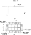
- the cross-sectional shape of the connection buoyancy section 90 is a rectangular shape. Therefore, there is a problem that large equivalent stress is easily generated in corner portions of the rectangular cross section of the connection buoyancy section 90 and a central portion of each side of the rectangular cross section in a case where large water pressure acts at a location where the water depth is deep.
- Patent Document 2 discloses a spar type floating body type wind turbine power-generating facility.
- a floating body section of the wind turbine power-generating facility is composed of concrete precast tubular bodies stacked in a plurality of stages in a height direction and integrated by tightly linking the respective precast tubular bodies by PC steel, and has a bottomed hollow portion having an open upper end portion.
- the floating body section has sufficient performance during wind-power generation operation.
- Patent Document 2 is a technique having a limit with respect to an increase in the size of a structure.
- the spar type floating body structure disclosed in Patent Document 3 includes: a cylindrical column section having a peripheral surface exposed to a waterline at the time of floating; a ballast section disposed at a lower portion of the column section; and a flange section disposed at an intermediate portion of the column section.
- the floating body structure configured in this manner is developed for the purpose of facilitating the installation or the maintenance of the floating body structure by a working ship and is not intended to solve a durability problem associated with an increase in size.
- the spar type floating body structure disclosed in Patent Document 4 includes: a hollow lower floating body made by joining upper and lower lid bodies to a tubular precast concrete block continuously installed between the lid bodies using PC steel; a hollow upper floating body joined to the lower floating body using PC steel and composed of an upper lid and a precast concrete block having a smaller diameter than the precast concrete block described above; and a ballast tank joined to the lower surface of the lower floating body through a connecting steel pipe.
- the present invention has been made in view of the above-mentioned circumstances and has an object to provide a floating body structure in which it is possible to secure structural strength capable of countering water pressure without increasing the amount of steel or the like which is used in a wall, even in a case where the floating body stricture is floated in water with the whole of the floating body structure sunk under water at a predetermined water depth in order to reduce the influence of sea waves, and it becomes possible to obtain the buoyancy needed to float the floating body structure at a predetermined water depth, and which has a larger flexural strength.
- the present invention adopts the following measures in order to achieve the above object by solving the above-described problems.
- the floating body structure According to the floating body structure according to the aspect of the above (1), it is possible to secure structural strength capable of countering water pressure without increasing the amount of steel or the like which is used in a wall, even in a case where the floating body structure is floated in water with the whole sunk under water at a predetermined water depth in order to reduce the influence of sea waves, and it becomes possible to obtain the buoyancy needed to float the floating body structure at a predetermined water depth. In addition, it becomes possible to secure sufficient flexural strength.
- the position of the first joint portion of the inner pipe is at a steel sheet portion of the outer pipe at the same position in the longitudinal direction and the position of the second joint portion of the outer pipe is at a steel sheet portion of the inner pipe at the same position in the longitudinal direction, and thus a configuration is made in which the first joint portion of the inner pipe and the second joint portion of the outer pipe are not present in the same cross section in the longitudinal direction. Due to this, it is possible to disperse joint portions which would likely lower total strength if in the same cross section, and thus it becomes possible to prevent the breakage of the floating body section having a double pipe structure.
- welding of the inner pipe and the outer pipe in the longitudinal direction is replaced by a spiral bead.
- Welding of the spiral bead is welding automated in a factory, and therefore, it becomes possible to provide a floating body section having a double pipe structure with a reduced manufacturing cost.
- the spiral bead acts as a shift stop, and therefore, the spiral bead contributes to the combining of internal concrete and a steel pipe portion, and thus it becomes possible to obtain higher structural strength.
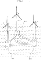
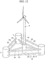
- a floating body structure 1 supports an object to be supported (superstructure 4) such as a wind turbine generator so that the superstructure 4 floats in the sea, and is provided below the superstructure 4 in association with the superstructure 4.
- the floating body structure 1 is floated in water in a state where the whole of the floating body structure 1 is sunk under water at a predetermined water depth, and at least a portion of the superstructure 4 is installed above a surface of the sea due to the buoyancy of the floating body structure 1.
- the floating body structure 1 is moored at a predetermined location in water by a mooring cable (not shown).
- the floating body structure 1 includes a floating body section 3 connected to a base end portion 4a of the superstructure 4.
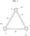
- the floating body structure 1 includes three floating body sections 3.
- the floating body structure 1 is formed in a substantially triangular planar shape with the three floating body sections 3 configured to support the three superstructures 4 as the apexes of the triangular planar shape and three floating body connecting sections 23 connecting the floating body sections 3 as three sides of the triangular planar shape.
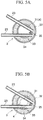
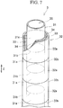
- the floating body section 3 has a substantially cylindrical double pipe structure having a substantially cylindrical inner pipe 31 made of steel, which is provided on the inside, and a substantially cylindrical outer pipe 32 made of steel, which is provided on the outside. Further, as shown in FIGS. 4A and 4B , the floating body section 3 includes a lid body 39 made of steel.
- the floating body section 3 is hermetically sealed by the lid bodies 39 in a state where at least a portion of a gap 33 formed between the outer wall surface of the inner pipe 31 and the inner wall surface of the outer pipe 32 is filled with concrete or mortar 34. That is, each of an upper end of the floating body section 3 and a lower end of the floating body section 3 is closed by the lid body 39.
- the floating body section 3 has a hollow portion 35 formed on the inside by the inner wall surface of the inner pipe 31.
- the entirety of the gap 33 may be filled with the concrete or mortar 34. Otherwise, a configuration is also acceptable in which a portion of the gap 33 is filled with the concrete or mortar 34 and the remaining space is used as a space configured to be filled with ballast.
- a supporting member configured to support the inner pipe 31 may be provided in the gap 33 between the outer wall surface of the inner pipe 31 and the inner wall surface of the outer pipe 32.
- each of the inner pipe 31 and the outer pipe 32 is not limited to a cylindrical pipe and may be, for example, an elliptical pipe or a polygonal pipe.
- the floating body section 3 may be continuous with the superstructure 4 in a form in which the inner pipe 31 is extended.
- the inner pipe 31 may be an extended portion of the base end portion 4a of the superstructure 4.
- the base end portion 4a of the superstructure 4 may be inserted into the inside (the hollow portion 35) of the inner pipe 31.
- the inner pipe 31 and the base end portion 4a are joined to each other by filling the space between the inner pipe 31 and the base end portion 4a with the concrete or mortar 34.
- the inner pipe 31 and the base end portion 4a may be joined to each other by using bolts or welding.
- the floating body sections 3 are connected to each other by the floating body connecting section 23.
- the floating body connecting section 23 may be joined to the outer pipe 32 of the floating body section 3 by welding or bolts.
- the floating body connecting section 23 can also be stuck from the side of the floating body section 3 and then joined to the floating body section 3.
- the floating body connecting section 23 may have a double pipe structure composed of an inner pipe and an outer pipe, similar to the floating body section 3, or may have a general single pipe structure. In a case of adopting a double pipe structure as the structure of the floating body connecting section 23, at least a portion of the gap between an inner pipe and an outer pipe may be filled with concrete or mortar, in a manner similar to the floating body section 3.
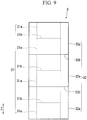
- the inner pipe 31 has first joint portions 31b which join a plurality of short steel pipes 31a for inner pipe each having a predetermined length, in a longitudinal direction Z of the floating body section 3.
- the outer pipe 32 has second joint portions 32b which join a plurality of short steel pipes 32a for outer pipe each having a predetermined length, in the longitudinal direction Z.
- the first joint portion 31b and the second joint portion 32b are alternately disposed in the longitudinal direction Z.
- each of the steel pipe 31 a for inner pipe and the steel pipe 32a for outer pipe may be a bent steel pipe obtained by bending and press-forming a steel sheet into a cylindrical shape.
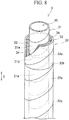
- each of the steel pipe 31a for inner pipe and the steel pipe 32a for outer pipe may be a spiral steel pipe obtained by press-forming a steel strip into a cylindrical shape by spirally bending the steel strip.
- the inner pipe 31 need not be configured with the plurality of steel pipes 31a for inner pipe and may be configured with a single bent steel pipe obtained by press-forming a single steel sheet into a cylindrical shape, or a single spiral steel pipe obtained by press-forming a steel strip into a cylindrical shape by spirally bending the steel strip.
- the outer pipe 32 also need not be configured with the plurality of steel pipes 32a for outer pipe and may be configured with a single bent steel pipe obtained by press-forming a single steel sheet into a cylindrical shape, or a single spiral steel pipe obtained by press-forming a steel strip into a cylindrical shape by spirally bending the steel strip.
- the position of the first joint portion 31b of the inner pipe 31 is at a steel sheet portion of the outer pipe 32 at the same position in the longitudinal direction Z
- the position of the second joint portion 32b of the outer pipe 32 is at a steel sheet portion of the inner pipe 31 at the same position in the longitudinal direction Z.
- the first joint portion 31b of the inner pipe 31 and the second joint portion 32b of the outer pipe 32 are alternately disposed in the longitudinal direction Z, and therefore, the first joint portion 31b of the inner pipe 31 and the second joint portion 32b of the outer pipe 32 are not present in the same cross section in the longitudinal direction Z.
- the floating body section 3 having such a structure, it is possible to disperse stress concentration of joint portions which would likely lower total strength if in the same cross section in the longitudinal direction Z, and as a result, it becomes possible to prevent the breakage of the floating body section 3. Further, even in a case where one of the inner pipe 31 and the outer pipe 32 is damaged, it becomes possible to secure the required structural strength of the floating body section 3 by the other of the inner pipe 31 and the outer pipe 32, which is not damaged. In this manner, the floating body section 3 has a fail-safe structure against overall breakage.
- the floating body section 3 has a double pipe structure, whereby it is possible to reduce the sheet thickness of each steel pipe which is used as the steel pipe 31a for inner pipe and the steel pipe 32a for outer pipe, and as a result, it is possible to reduce the degree of difficulty of welding in the first joint portion 31b and the second joint portion 32b. Therefore, according to the floating body structure 1 according to this embodiment, it becomes possible to use high-strength steel as the steel pipe 31a for inner pipe and the steel pipe 32a for outer pipe.
- the steel structure was configured with a relatively thin plate. For this reason, in a case where the steel structure is a rectangular structure, if water pressure acts from the side of the rectangular structure, a bending moment occurring in a steel sheet significantly increases. Even in a case where the steel structure has a circular cross-sectional shape, a large axial force acts on a steel sheet, and therefore, the sheet thickness becomes very large in order to secure structural strength against buckling.
- the filled concrete or mortar 34 not only hardly generates bending stress in order to support the steel materials of the inner pipe 31 and the outer pipe 32 from the side, but also has the effect of limiting the occurrence of buckling by restraint, thereby being structurally very reasonable.
- the concrete or mortar 34 which is filled into the gap 33 counters stress which acts on the floating body section 3 in a compression direction, it is possible to reduce structural strength in the compression direction which is required for the steel pipe 31a for inner pipe and the steel pipe 32a for outer pipe. For this reason, in the floating body structure 1 according to this embodiment, it is sufficient if the inner pipe 31 and the outer pipe 32 are designed so as to secure structural strength in a tensile direction, and thus it is possible to reduce the amount of steel which is used for the steel pipe 31a for inner pipe and the steel pipe 32a for outer pipe.
- the structural strength in the compression direction which is required for the steel pipe 31a for inner pipe and the steel pipe 32a for outer pipe is reduced, and therefore, even in a case where high-strength steel is used as the steel pipe 31a for inner pipe and the steel pipe 32a for outer pipe, it is possible to limit a reduction in buckling stress due to use of high-strength steel.
- connection buoyancy section 90 of the related art Comparing the floating body structure 1 with the connection buoyancy section 90 having a rectangular cross section of the related art shown in FIG. 20 , in the connection buoyancy section 90 of the related art, it is necessary to provide the stiffener 92 perpendicular to a wall surface inside a wall in order to secure a predetermined structural strength. For this reason, a weight of steel of, for example, 22 tons/m is required. In contrast, in the floating body structure 1 it becomes possible to secure structural strength equivalent to that of the connection buoyancy section 90 of the related art with a weight of steel of 1.2 tons/m.
- the floating body structure 1 it is possible to fabricate the floating body structure 1 with a used amount of steel of about 5%, as compared to the connection buoyancy section 90 having a rectangular cross section of the related art, and thus it becomes possible to provide a floating body type wind turbine power-generating facility at a significantly reduced manufacturing cost.
- the floating body structure 1 in a case where a spiral steel pipe is used as the steel pipe 31a for inner pipe and the steel pipe 32a for outer pipe, it is possible to use a hot coil in the manufacturing of the steel pipe. As a result, it is possible to reduce the manufacturing cost of the steel pipe, as compared to a case of using a thick steel plate. Further, it is possible to make the lengths of the steel pipe 31a for inner pipe and the steel pipe 32a for outer pipe longer, and thus it is possible to significantly reduce the number of first joint portions 31b and the second joint portions 32b or completely eliminate the first joint portion 31b and the second joint portion 32b. For this reason, according to the floating body structure 1 of this embodiment, it is possible to significantly reduce the cost required for welding.
- the floating body structure 1 according to this embodiment, welding of the inner pipe 31 and the outer pipe 32 in the longitudinal direction Z is replaced by a spiral bead.
- the spiral bead is uniformly disposed over the entire length of the steel pipe, and therefore, the spiral bead very effectively functions as a shift stop for the concrete or mortar 34 which is filled in. Therefore, according to the floating body structure 1 the structural strength of the floating body section 3 is increased and it becomes possible to provide the floating body section 3 at a reduced manufacturing cost.
- corrosion protection means may be provided on the inner wall surface of the inner pipe 31 in order to prevent corrosion by the seawater 5 or the like injected into the hollow portion 35.
- the gap 33 (the thickness of the concrete or mortar 34) between the outer wall surface of the inner pipe 31 and the inner wall surface of the outer pipe 32 is 600 mm or more, and it is preferable that at least a portion of the outer diameter of the outer pipe 32 is 6500 mm or more. This is because in a case of adopting a double pipe structure as the structure of the floating body section 3, it is realistically necessary for a worker to enter between the inner tube 31 and the outer tube 32 and perform work in a process of fabricating the floating body section 3.
- the floating body section 3 is fabricated by, for example, the following processes.
- a plurality of steel pipes 31a for inner pipe are joined in series along a vertical direction on a horizontal plane (hereinafter referred to as a working surface) which is used to perform work of fabricating the floating body section 3, whereby the inner pipe 31 which is upright with respect to the working surface is fabricated.
- a plurality of steel pipes 32a for outer pipe are joined in series along the vertical direction, whereby the outer pipe 32 which is upright with respect to the working surface and accommodates the inner pipe 31 on the inside thereof is fabricated.
- the space between the inner pipe 31 and the outer pipe 32 is filled with the concrete or mortar 34. At this time, it is necessary for a worker to enter between the inner pipe 31 and the outer pipe 32 and perform filling work.
- a longer inner pipe 31 is fabricated by joining a plurality of steel pipes 31a for inner pipe in series along the vertical direction with respect to the inner pipe 31 fabricated first. At this time, it is necessary for a worker to enter between the inner pipe 31 and the outer pipe 32 and perform joining work.
- a longer outer pipe 32 is fabricated by joining a plurality of steel pipes 32a for outer pipe in series along the vertical direction with respect to the outer pipe 32 fabricated first. Also at this time, it is necessary for a worker to enter between the inner pipe 31 and the outer pipe 32 and perform joining work. Then, the space between the inner pipe 31 and the outer pipe 32 made longer is filled with the concrete or mortar 34. As described above, a floating body section 3 having a predetermined length is fabricated by repeating the process of sequentially filling the space between the inner pipe 31 and the outer pipe 32 with the concrete or mortar 34 while gradually extending the lengths of the inner pipe 31 and the outer pipe 32.
- the gap 33 in the floating body section 3 is 600 mm or more, and it is preferable that at least a portion of the outer diameter of the outer pipe 32 is 6500 mm or more.
- the strength of the joint portion of each of the inner pipe 31 and the outer pipe 32 is reduced, and therefore, it is necessary to add reinforcement parts to the inside of the inner pipe 31 and the outside of the outer pipe 32.
- the inventor of this application calculated a sheet thickness, a generated stress, a ballast amount, and a steel weight in a case of supporting a wind turbine power-generating facility by using the floating body section 3 having a double pipe structure and a case of supporting the same wind turbine power-generating facility by using a floating body section having a general single pipe structure of the related art, by simulation.
- the calculation results are shown in Table 1.
- the weight of a section on water was set to be 550 tons such that the weight of a submerged section (including ballast) of the entire structure which includes the wind turbine power-generating facility and the floating body section became greater than or equal to ten times the weight of the section on water and the buoyancy and the total weight of the entire structure balanced each other, and the diameter of the floating body section was set to be 9 m, and the length of the floating body section was set to be 90 m.
- the reason why the weight of the submerged section is set to ten times or more the weight of the section on water is because it is the estimate of a weight ratio in which it is possible to obtain stability as a floating body.
- the above-mentioned ballast is a heavy load which is filled into an internal space of the floating body section in order to adjust the weight balance of the entire structure such that the weight of the submerged section becomes ten times or more the weight of the section on water and to make the buoyancy and the total weight of the entire structure balance each other.
- a design strength of an upper end portion of the floating body section was designed so as to be larger than a load which is generated due to a moment which is transmitted from a steel pipe, and a lower end portion of the floating body section was designed so as to be able to withstand water pressure.
- An allowable stress was set to be a value which is obtained by dividing yield strength by a safety factor of 1.5.
- a case of using SM490 as steel was assumed.
- the Young's modulus ratio of concrete and steel was set to be 7.
- the floating body structure 1 it becomes possible to provide the floating body section 3 in which structural strength capable of countering water pressure is secured without increasing the used amount of steel or the like, even in a case where the whole is sunk under water and floated in water at a predetermined water depth in order to reduce the influence of sea waves.
- the floating body structure 1A includes: a single superstructure support 2 configured to support a single superstructure 4; the three floating body sections 3 which are provided on the side of the superstructure support 2; the floating body connecting sections 23 connecting the three floating body sections 3 to each other; and support connecting sections 24 connecting the superstructure support 2 and the floating body sections 3.
- the floating body structure 1A is moored at a predetermined location in water by a mooring cable (not shown).
- the superstructure support 2 also has a double pipe structure, similar to the floating body section 3. That is, the superstructure support 2 has a structure in which the inner pipe 31 is continuous with the superstructure 4 (a structure in which the inner pipe 31 is an extended portion of the base end portion 4a of the superstructure 4) or a structure in which the base end portion 4a of the superstructure 4 is inserted into the inside (the hollow portion 35) of the inner pipe 31.
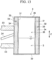
- the floating body section 3 has a substantially cylindrical double pipe structure having the substantially cylindrical inner pipe 31 made of steel, which is provided on the inside, and the substantially cylindrical outer pipe 32 made of steel, which is provided on the outside.
- the up-down direction of the floating body section 3 is the longitudinal direction Z.
- the floating body section 3 is hermetically sealed in a state where at least a portion (in FIG. 13 , the whole as an example) of the gap 33 formed between the outer wall surface of the inner pipe 31 and the inner wall surface of the outer pipe 32 is filled with the concrete or mortar 34.
- the floating body section 3 has the hollow portion 35 formed on the inside by the inner wall surface of the inner pipe 31.
- Each of the upper end of the floating body section 3 and the lower end of the floating body section 3 is closed by the lid body 39.
- the floating body structure 1A according to the second embodiment example can be sunk in water by reducing the buoyancy of the floating body structure 1A by injecting the seawater 5 or the like into the hollow portion 35 of the floating body section 3 by using injection means (not shown) in deep water where the superstructure 4 is installed.
- the floating body structure 1A of the second example as described above it is possible to secure structural strength capable of countering water pressure without increasing the used amount of steel or the like even in a case where the whole of the floating body structure 1A is sunk and floated in water at a predetermined water depth in order to reduce the influence of sea waves, and it becomes possible to obtain the buoyancy needed to float the floating body structure 1A at a predetermined water depth.
- the floating body structure 1B includes: the single superstructure support 2 configured to support the single superstructure 4; the floating body section 3 provided below the superstructure support 2; and a plurality of fins 38 which are provided on the lower side of the floating body section 3 for balancing the superstructure 4 and the floating body structure 1B in the sea.
- the floating body structure 1B is moored at a predetermined location in water by a mooring cable (not shown).
- the superstructure support 2 has a substantially cylindrical concrete block body 21.
- the base end portion 4a of the superstructure 4 is mounted in an upper end portion 2a having a substantially circular planar shape. Due to such a structure, the superstructure support 2 supports the superstructure 4.
- the floating body section 3 has a substantially cylindrical double pipe structure having the substantially cylindrical inner pipe 31 made of steel, which is provided on the inside, and the substantially cylindrical outer pipe 32 made of steel, which is provided on the outside.
- the up-down direction of the floating body section 3 is the longitudinal direction Z.
- the floating body section 3 is hermetically sealed in a state where at least a portion (in FIG. 15 , the whole as an example) of the gap 33 formed between the outer wall surface of the inner pipe 31 and the inner wall surface of the outer pipe 32 is filled with the concrete or mortar 34.
- the floating body section 3 has the hollow portion 35 formed on the inside by the inner wall surface of the inner pipe 31.
- the floating body structure 1B according to the third example can be sunk in water by reducing the buoyancy of the floating body structure 1B by injecting the seawater 5 or the like into the hollow portion 35 of the floating body section 3 by using injection means (not shown) in deep water where the superstructure 4 is installed.
- the floating body structure 1B of the third example as described above it is possible to secure structural strength capable of countering water pressure without increasing the used amount of steel or the like even in a case where the whole is sunk under water and floated in water at a predetermined water depth in order to reduce the influence of sea waves, and it becomes possible to obtain the buoyancy needed to float the floating body structure 1B at a predetermined water depth.
- the superstructure 4 in the third example may have a structure in which the superstructure 4 is continuous with the inner pipe 31 of the floating body section 3 having a double pipe structure (a structure in which the inner pipe 31 is the extended portion of the base end portion 4a of the superstructure 4).
- the superstructure 4 in the third embodiment may have a structure in which the base end portion 4a is inserted into the inside (the hollow portion 35) of the inner pipe 31 of the floating body section 3 having a double pipe structure.
- the superstructure 4 and the inner pipe 31 may be joined to each other by filling the space between the superstructure 4 and the inner pipe 31 with mortar or concrete. Otherwise, in the case of the structure shown in FIG. 16B , the superstructure 4 and the inner pipe 31 may be joined to each other by using bolts or welding.
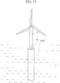
- the floating body structure 1C includes the single floating body section 3 configured to support the single superstructure 4.
- the floating body structure 1C is moored at a predetermined location in water by a mooring cable (not shown).
- the floating body section 3 has a substantially cylindrical double pipe structure having the substantially cylindrical inner pipe 31 made of steel, which is provided on the inside, and the substantially cylindrical outer pipe 32 made of steel, which is provided on the outside.
- the up-down direction of the floating body section 3 is the longitudinal direction Z.
- the floating body section 3 is hermetically sealed in a state where at least a portion (in FIG. 18 , the whole as an example) of the gap 33 formed between the outer wall surface of the inner pipe 31 and the inner wall surface of the outer pipe 32 is filled with the concrete or mortar 34.
- the floating body section 3 has the hollow portion 35 formed on the inside by the inner wall surface of the inner pipe 31.
- the floating body structure 1C according to the fourth example can be sunk under water by reducing the buoyancy of the floating body structure 1C by injecting the seawater 5 or the like into the hollow portion 35 of the floating body section 3 by using injection means (not shown) in deep water where the superstructure 4 is installed.
- the floating body structure 1C of the fourth example as described above, it is possible to secure structural strength capable of countering water pressure without increasing the used amount of steel or the like even in a case where the whole of the floating body structure 1C is sunk under water and floated in water at a predetermined water depth in order to reduce the influence of sea waves, and it becomes possible to obtain the buoyancy needed to float the floating body structure 1C at a predetermined water depth.
- the floating body structure 1C according to the fourth example can be raised up from a state of lying sideways, by a crane or injection into the hollow portion 35.
- the floating body section 3 has very large flexural strength because of being a double pipe structure filled with the concrete or mortar 34. Further, even in a case where cracks are generated in the concrete or mortar 34 filled into the floating body section 3 while the floating body structure 1C is raised up, since the concrete or mortar 34 is completely covered with steel and does not come into direct contact with water, a durability problem does not occur.
- the superstructure 4 in the example embodiment may have a structure in which the superstructure 4 is continuous with the inner pipe 31 of the floating body section 3 having a double pipe structure (a structure in which the inner pipe 31 is the extended portion of the base end portion 4a of the superstructure 4) (refer to FIG. 16A ), similar to the third embodiment.
- the superstructure 4 in the fourth example may have a structure in which the base end portion 4a is inserted into the inside (the hollow portion 35) of the inner pipe 31 of the floating body section 3 having a double pipe structure (refer to FIG. 16B ), similar to the third embodiment.
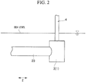
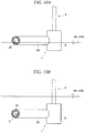
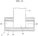
- the superstructure 4 and the floating body section 3 may not be connected such that the central axis of the superstructure 4 and the central axis of the floating body section 3 (that is, the central axis of the inner pipe 31 and the outer pipe 32) necessarily coincide with each other, as described in each of the above-described embodiments.
- the base end portion 4a of the superstructure 4 may penetrate toward the inside of the inner pipe 31 from the outside in the radial direction of the inner pipe 31 and the outer pipe 32.
- the superstructure 4 and the floating body section 3 may be connected to each other so that the central axis of the superstructure 4 and the central axis of the floating body section 3 are orthogonal to each other.
- the superstructure 4 may be fixed to the floating body section 3 by filling the hollow portion 35 which is formed by the inner wall surface of the inner pipe 31 with concrete or mortar 34' at a position where the base end portion 4a penetrates.
Claims (7)
- Schwimmkörperkonstruktion (1), die so konfiguriert ist, dass sie ein zu tragendes Objekt (4) trägt, so dass das zu tragende Objekt (4) im Meer schwimmt, mit:einem Schwimmkörperteilstück (3), das konfiguriert ist, um mit einem Basisendabschnitt (4a) des zu tragenden Objekts (4) so verbunden zu werden, dass eine Mittelachse des zu tragenden Objekts (4) und eine Mittelachse des Schwimmkörperteilstücks (3) orthogonal zueinander sind,wobei das Schwimmkörperteilstück (3) aufweist: ein aus Stahl hergestelltes Außenrohr (32); ein aus Stahl hergestelltes und innerhalb des Außenrohrs (32) vorgesehenes Innenrohr (31); ein erstes fluidverfestigtes Material (34), das in zumindest einen Abschnitt eines Spalts (33) zwischen einer Außenwandfläche des Innenrohrs (31) und einer Innenwandfläche des Außenrohrs (32) gefüllt ist; ein zweites fluidverfestigtes Material (34'), das in einen Hohlabschnitt (35), der durch eine Innenwandfläche des Innenrohrs (31) gebildet ist, gefüllt ist; und einen aus Stahl hergestellten Deckelkörper (39), der das Schwimmkörperteilstück (3) hermetisch abdichtet,wobei das erste fluidverfestigte Material (34) und das zweite fluidverfestigte Material (34') Beton oder Mörtel sind,wobei das Innenrohr (31) und das Außenrohr (32) so konfiguriert sind, dass der Basisendabschnitt (4a) des zu tragenden Objekts (4) von außen in einer Radialrichtung des Innenrohrs (31) und des Außenrohrs (32) zum Inneren des Innenrohrs (31) durchdringen kann, unddas Innenrohr (31) und das zweite fluidverfestigte Material (34') so konfiguriert sind, dass der Basisendabschnitt (4a) durch das zweite fluidverfestigte Material (34'), das in den Hohlabschnitt (35) des Innenrohrs (31) an einer Position gefüllt ist, die so konfiguriert ist, dass der Basisendabschnitt (4a) durchdringen kann, am Schwimmkörperteilstück (3) befestigt ist.
- Schwimmkörperkonstruktion (1) nach Anspruch 1,
wobei das Innenrohr (31) einen ersten Verbindungsabschnitt (31b) hat, der mehrere Stahlrohre (31a) für das Innenrohr mit jeweils einer vorbestimmten Länge in einer Längsrichtung des Schwimmkörperteilstücks (3) verbindet,
das Außenrohr (32) einen zweiten Verbindungsabschnitt (32b) hat, der mehrere Stahlrohre (32a) für das Außenrohr mit jeweils einer vorbestimmten Länge in der Längsrichtung verbindet, und
der erste Verbindungsabschnitt (31b) und der zweite Verbindungsabschnitt (32b) in der Längsrichtung abwechselnd angeordnet sind. - Schwimmkörperkonstruktion (1) nach Anspruch 2,
wobei das Stahlrohr (31a) für das Innenrohr und das Stahlrohr (32a) für das Außenrohr jeweils ein Spiralstahlrohr ist, das durch Pressformen eines Stahlbands in eine Zylinderform durch Spiralbiegen des Stahlbands erhalten ist. - Schwimmkörperkonstruktion (1) nach einem der Ansprüche 1 bis 3,
wobei das Innenrohr (31) ein verlängerter Abschnitt des Basisendabschnitts (4a) des zu tragenden Objekts (4) ist. - Schwimmkörperkonstruktion (1) nach einem der Ansprüche 1 bis 4,
wobei der Basisendabschnitt (4a) des zu tragenden Objekts (4) in das Innenrohr (31) eingeführt ist und
ein Hohlabschnitt (35), der durch eine Innenwandfläche des Innenrohrs (31) gebildet ist, mit Beton oder Mörtel (34) an einer Position gefüllt ist, an der der Basisendabschnitt (4a) eingeführt ist. - Schwimmkörperkonstruktion (1) nach einem der Ansprüche 1 bis 5,
wobei mehrere der Schwimmkörperteilstücke (3) vorgesehen sind und
die mehreren Schwimmkörperteilstücke (3) durch ein Schwimmkörper-Verbindungsteilstück (23) miteinander verbunden sind. - Schwimmkörperkonstruktion (1) nach einem der Ansprüche 1 bis 6,
wobei der Spalt (33) zwischen der Außenwandfläche des Innenrohrs (31) und der Innenwandfläche des Außenrohrs (32) mindestens 600 mm beträgt und mindestens ein Abschnitt eines Außendurchmessers des Außenrohrs (32) mindestens 6500 mm beträgt.
Priority Applications (1)
| Application Number | Priority Date | Filing Date | Title |
|---|---|---|---|
| EP20153955.8A EP3686426A1 (de) | 2013-04-01 | 2014-03-31 | Schwimmkörperstruktur |
Applications Claiming Priority (3)
| Application Number | Priority Date | Filing Date | Title |
|---|---|---|---|
| JP2013076294 | 2013-04-01 | ||
| EP14779046.3A EP2993345B1 (de) | 2013-04-01 | 2014-03-31 | Schwimmende struktur |
| PCT/JP2014/059407 WO2014163032A1 (ja) | 2013-04-01 | 2014-03-31 | 浮体構造物 |
Related Parent Applications (1)
| Application Number | Title | Priority Date | Filing Date |
|---|---|---|---|
| EP14779046.3A Division EP2993345B1 (de) | 2013-04-01 | 2014-03-31 | Schwimmende struktur |
Related Child Applications (2)
| Application Number | Title | Priority Date | Filing Date |
|---|---|---|---|
| EP20153955.8A Division EP3686426A1 (de) | 2013-04-01 | 2014-03-31 | Schwimmkörperstruktur |
| EP20153955.8A Division-Into EP3686426A1 (de) | 2013-04-01 | 2014-03-31 | Schwimmkörperstruktur |
Publications (2)
| Publication Number | Publication Date |
|---|---|
| EP3382201A1 EP3382201A1 (de) | 2018-10-03 |
| EP3382201B1 true EP3382201B1 (de) | 2020-03-25 |
Family
ID=51658328
Family Applications (3)
| Application Number | Title | Priority Date | Filing Date |
|---|---|---|---|
| EP20153955.8A Withdrawn EP3686426A1 (de) | 2013-04-01 | 2014-03-31 | Schwimmkörperstruktur |
| EP14779046.3A Not-in-force EP2993345B1 (de) | 2013-04-01 | 2014-03-31 | Schwimmende struktur |
| EP18160087.5A Active EP3382201B1 (de) | 2013-04-01 | 2014-03-31 | Schwimmkörperstruktur |
Family Applications Before (2)
| Application Number | Title | Priority Date | Filing Date |
|---|---|---|---|
| EP20153955.8A Withdrawn EP3686426A1 (de) | 2013-04-01 | 2014-03-31 | Schwimmkörperstruktur |
| EP14779046.3A Not-in-force EP2993345B1 (de) | 2013-04-01 | 2014-03-31 | Schwimmende struktur |
Country Status (8)
| Country | Link |
|---|---|
| US (1) | US9533738B2 (de) |
| EP (3) | EP3686426A1 (de) |
| JP (1) | JP5741881B2 (de) |
| KR (1) | KR101589888B1 (de) |
| CN (1) | CN104884794B (de) |
| DK (2) | DK2993345T3 (de) |
| ES (2) | ES2795284T3 (de) |
| WO (1) | WO2014163032A1 (de) |
Families Citing this family (22)
| Publication number | Priority date | Publication date | Assignee | Title |
|---|---|---|---|---|
| DE102013222081B4 (de) * | 2013-10-30 | 2016-05-12 | Gicon Windpower Ip Gmbh | In der offenen See schwimmendes und über Abspannmittel mit Ankern verbundenes Tragwerk für Windkraftanlagen, Servicestationen oder Konverterstationen |
| EP3310647B1 (de) * | 2015-06-19 | 2021-03-24 | Principle Power, Inc. | Schwimmende windturbinenplattformstruktur mit optimiertem transfer von wellen- und windlasten |
| FR3052817B1 (fr) * | 2016-06-20 | 2018-07-06 | Ceteal | Dispositif flottant support d'eolienne offshore et ensemble eolien flottant correspondant |
| ES2797104T3 (es) * | 2016-12-27 | 2020-12-01 | Nautilus Floating Solutions Sl | Plataforma marítima flotante |
| US10196112B2 (en) * | 2017-03-16 | 2019-02-05 | Dalian University Of Technology | Adaptive observation platform device for sea surface |
| DE102019118564B4 (de) * | 2019-07-09 | 2021-03-11 | Aerodyn Consulting Singapore Pte Ltd | Windenergieanlage mit einem eine Mehrzahl von Auftriebskörpern aufweisenden schwimmenden Fundament |
| KR102107994B1 (ko) * | 2019-08-14 | 2020-05-07 | 주식회사 에이스이앤티 | 해상 풍력발전 부유체 |
| JP2022549633A (ja) * | 2019-09-25 | 2022-11-28 | クローヴァス アクティーゼルスカブ | 浮体式金属プラットフォーム |
| JP7433859B2 (ja) * | 2019-11-26 | 2024-02-20 | 三菱重工業株式会社 | 風力発電装置の支持構造及び風力発電装置 |
| SE544127C2 (en) * | 2020-04-30 | 2022-01-04 | Bassoe Tech Ab | Floating semi-submersible wind energy platform with t-shaped pontoon and its assembly |
| IT202000011779A1 (it) * | 2020-05-20 | 2021-11-20 | Seawind Ocean Tech Holding B V | Piattaforma flottante semisommergibile per sistemi offshore di conversione dell’energia elettrica e metodo per la realizzazione di tale piattaforma |
| CN111688874A (zh) * | 2020-05-27 | 2020-09-22 | 中交第二公路工程局有限公司 | 一种浪涌条件下的组合式稳定平台及应用 |
| JP7447695B2 (ja) | 2020-06-22 | 2024-03-12 | 東京電力ホールディングス株式会社 | 柱状型浮体、及び柱状型浮体製造方法 |
| DE102020116742B4 (de) | 2020-06-25 | 2024-05-02 | GICON-Großmann Ingenieur Consult GmbH | Universalauftriebskörper, Verfahren zur Herstellung eines Universalauftriebskörpers und dessen Verwendung |
| EP4323644A1 (de) * | 2021-04-12 | 2024-02-21 | Stiesdal Offshore A/S | Offshore-windturbinensystem und offshore-plattform |
| CN112977743A (zh) * | 2021-04-14 | 2021-06-18 | 哈尔滨工业大学(深圳) | 一种半潜式风机基座及漂浮式风机 |
| WO2023284926A1 (en) * | 2021-07-12 | 2023-01-19 | Stiesdal Offshore A/S | A floating offshore support structure, especially for an offshore wind turbine, its assembly method and use as well as a precursor frame structure |
| CN113772037A (zh) * | 2021-09-17 | 2021-12-10 | 清华大学 | 海上大型钢-混凝土组合浮式半潜平台结构 |
| SE545065C2 (en) * | 2022-01-14 | 2023-03-21 | Bassoe Tech Ab | Hull structure for a semi-submersible wind power turbine platform, related loading method and vessel for transportation of said hull structure |
| IT202200004748A1 (it) * | 2022-03-11 | 2023-09-11 | Fincantieri Spa | Galleggiante per il supporto di un generatore eolico offshore |
| NL2032274B1 (en) * | 2022-06-24 | 2024-01-09 | Maridea B V | Floating Foundation and Method of Construction |
| JP7423027B1 (ja) | 2023-03-09 | 2024-01-29 | 會澤高圧コンクリート株式会社 | 洋上風力発電設備の浮体基礎建築の建築方法 |
Family Cites Families (27)
| Publication number | Priority date | Publication date | Assignee | Title |
|---|---|---|---|---|
| FR1247968A (fr) * | 1959-10-15 | 1960-12-09 | Structure pour canalisations et autres applications | |
| DE1274318B (de) * | 1961-01-19 | 1968-08-01 | Driam A G | Schraubennahtrohr und Verfahren zu seiner Herstellung |
| US3860983A (en) * | 1969-10-31 | 1975-01-21 | Cameron Iron Works Inc | Controllably submersible buoy |
| CA1250491A (en) | 1984-10-22 | 1989-02-28 | Jacek S. Pawlowski | Semi-submersible drilling unit with cylindrical ring floats |
| US4606673A (en) * | 1984-12-11 | 1986-08-19 | Fluor Corporation | Spar buoy construction having production and oil storage facilities and method of operation |
| GB2322423B (en) * | 1997-02-17 | 1998-12-30 | T J Corbishley | Improvements in connecting tubular members |
| US6190089B1 (en) * | 1998-05-01 | 2001-02-20 | Mindoc, Llc | Deep draft semi-submersible offshore structure |
| US6726831B2 (en) * | 2001-07-20 | 2004-04-27 | Shell Oil Company | Corrosion protection of electrically heated pipe-in-pipe subsea pipeline |
| JP2004019470A (ja) | 2002-06-12 | 2004-01-22 | Mitsubishi Heavy Ind Ltd | 浮体式大型風力発電装置 |
| DE10337997B4 (de) | 2003-08-19 | 2005-11-10 | Zeljko Gajic | Befestigungsvorrichtung für eine Off-shore-Windenergieanlage |
| JP3895337B2 (ja) | 2004-05-19 | 2007-03-22 | 三井住友建設株式会社 | 塔状構造物 |
| JP5022797B2 (ja) | 2007-07-11 | 2012-09-12 | 五洋建設株式会社 | 洋上風力発電のスパー型浮体構造およびその製造方法 |
| JP5022976B2 (ja) | 2008-04-08 | 2012-09-12 | 五洋建設株式会社 | 洋上風力発電用のスパー型浮体構造およびその製造方法ならびにその設置方法 |
| EP2271547B1 (de) | 2008-04-23 | 2014-03-19 | Principle Power, Inc. | Säulenstabilisierte offshore-plattform mit wassereinschlussplatten und asymmetrischem andocksystem als träger von offshore-windturbinen |
| JPWO2010044380A1 (ja) * | 2008-10-15 | 2012-03-15 | 株式会社竹中工務店 | 塔状構造物、及び塔状構造物の構築方法 |
| WO2010093259A2 (en) * | 2009-02-13 | 2010-08-19 | Vest Kran Wind Power As | Offshore wind turbine |
| JP5330048B2 (ja) | 2009-03-24 | 2013-10-30 | 戸田建設株式会社 | 洋上風力発電設備の施工方法 |
| JP2010234965A (ja) * | 2009-03-31 | 2010-10-21 | Mitsui Eng & Shipbuild Co Ltd | 緊張係留浮体システム、支援用システム及びこの支援用システムを用いた浮体の曳航方法と設置方法 |
| US8251003B2 (en) * | 2009-11-08 | 2012-08-28 | Ssp Technologies, Inc. | Offshore buoyant drilling, production, storage and offloading structure |
| JP2011207446A (ja) * | 2010-03-30 | 2011-10-20 | Mitsui Eng & Shipbuild Co Ltd | 支援用浮体、支援用浮体を用いた浮体の曳航方法及び支援用浮体を用いた浮体の設置方法 |
| JP5736133B2 (ja) | 2010-07-23 | 2015-06-17 | ジャパンマリンユナイテッド株式会社 | 浮体構造物作業システム、作業船及び浮体構造物作業方法 |
| CN103282274B (zh) * | 2010-11-04 | 2017-03-29 | 缅因大学系统理事会 | 浮置混合复合材料风力涡轮机平台和塔架系统 |
| CN102060088A (zh) | 2010-12-01 | 2011-05-18 | 山东长星风电科技有限公司 | 海上组合式漂浮风力发电专用技术 |
| WO2012118186A1 (ja) * | 2011-03-02 | 2012-09-07 | 新日本製鐵株式会社 | 鋼管杭と鋼製外管との接合構造 |
| PL218742B1 (pl) | 2011-06-07 | 2015-01-30 | Vistal Wind Power Spółka Z Ograniczoną Odpowiedzialnością | Morska elektrownia wiatrowa oraz sposób stawiania morskiej elektrowni wiatrowej |
| JP5699888B2 (ja) | 2011-09-30 | 2015-04-15 | 株式会社協和製作所 | 浮体式起伏型ゲート設備 |
| CN102849186B (zh) * | 2012-09-27 | 2014-12-03 | 耿秀 | 水上浮岛 |
-
2014
- 2014-03-31 CN CN201480003675.XA patent/CN104884794B/zh not_active Expired - Fee Related
- 2014-03-31 EP EP20153955.8A patent/EP3686426A1/de not_active Withdrawn
- 2014-03-31 WO PCT/JP2014/059407 patent/WO2014163032A1/ja active Application Filing
- 2014-03-31 EP EP14779046.3A patent/EP2993345B1/de not_active Not-in-force
- 2014-03-31 JP JP2014535444A patent/JP5741881B2/ja not_active Expired - Fee Related
- 2014-03-31 EP EP18160087.5A patent/EP3382201B1/de active Active
- 2014-03-31 KR KR1020157016670A patent/KR101589888B1/ko active IP Right Grant
- 2014-03-31 DK DK14779046.3T patent/DK2993345T3/en active
- 2014-03-31 ES ES18160087T patent/ES2795284T3/es active Active
- 2014-03-31 ES ES14779046.3T patent/ES2671561T3/es active Active
- 2014-03-31 DK DK18160087.5T patent/DK3382201T3/da active
- 2014-03-31 US US14/651,323 patent/US9533738B2/en active Active
Non-Patent Citations (1)
| Title |
|---|
| None * |
Also Published As
| Publication number | Publication date |
|---|---|
| DK2993345T3 (en) | 2018-06-14 |
| US20150329180A1 (en) | 2015-11-19 |
| JP5741881B2 (ja) | 2015-07-01 |
| KR20150087407A (ko) | 2015-07-29 |
| EP2993345A4 (de) | 2017-01-04 |
| EP2993345A1 (de) | 2016-03-09 |
| CN104884794B (zh) | 2016-08-31 |
| EP3686426A1 (de) | 2020-07-29 |
| EP3382201A1 (de) | 2018-10-03 |
| EP2993345B1 (de) | 2018-03-21 |
| WO2014163032A1 (ja) | 2014-10-09 |
| ES2795284T3 (es) | 2020-11-23 |
| ES2671561T3 (es) | 2018-06-07 |
| KR101589888B1 (ko) | 2016-01-28 |
| DK3382201T3 (da) | 2020-04-27 |
| US9533738B2 (en) | 2017-01-03 |
| CN104884794A (zh) | 2015-09-02 |
| JPWO2014163032A1 (ja) | 2017-02-16 |
Similar Documents
| Publication | Publication Date | Title |
|---|---|---|
| EP3382201B1 (de) | Schwimmkörperstruktur | |
| JP4528652B2 (ja) | 水中構造物の仮締切工法及び仮締切用構造体 | |
| CN103228909B (zh) | 用于安装海上塔的方法 | |
| JP2010223114A (ja) | 洋上風力発電設備及びその施工方法 | |
| WO2010110329A1 (ja) | 洋上風力発電設備及びその施工方法 | |
| CN104594377A (zh) | 海上风机的钢筒型基础结构 | |
| BR112014009389B1 (pt) | processo para instalar uma torre offshore | |
| JP2010223114A5 (de) | ||
| KR20130055658A (ko) | 강관주 구조물 및 그의 제조 방법 | |
| CN104153384A (zh) | 海上夹心钢管桩基础及施工方法 | |
| EP4039969A1 (de) | Tragstruktur für eine windenergieanlage und windenergieanlage | |
| JP2017089134A (ja) | 締切工法および止水壁構造体 | |
| EP2930273B1 (de) | Fundament auf schwerkraftbasis für eine offshore-anlage | |
| KR102310131B1 (ko) | 부유 가능한 콘크리트 블록 구조물 및 그 제작 방법 | |
| KR20140051531A (ko) | 해양 지지구조물과 그 제조방법 및 시공방법 | |
| JP2012201218A (ja) | 洋上風力発電設備の施工方法 | |
| CN107476270A (zh) | 重力式导管架海上升压站 | |
| GB2505192A (en) | A pile sleeve connection for a monopole foundation | |
| CN102787988A (zh) | 一种海上风力发电机组安装方法 | |
| CN213038418U (zh) | 一种新型海上风电全钢筒型基础结构 | |
| CN113152496B (zh) | 一种用于钢护筒上牛腿水下焊接的封水套箱 | |
| CN105274985A (zh) | 一种内设多个弧形加劲肋的钢管桩及其施工方法 | |
| CN114855839A (zh) | 一种应用于水工构筑物的钢吊箱及其施工方法 | |
| CN204510256U (zh) | 海上风机的钢筒型基础结构 | |
| CN217267360U (zh) | 一种基于护筒定位的海上组合浮箱施工平台 |
Legal Events
| Date | Code | Title | Description |
|---|---|---|---|
| PUAI | Public reference made under article 153(3) epc to a published international application that has entered the european phase |
Free format text: ORIGINAL CODE: 0009012 |
|
| STAA | Information on the status of an ep patent application or granted ep patent |
Free format text: STATUS: REQUEST FOR EXAMINATION WAS MADE |
|
| 17P | Request for examination filed |
Effective date: 20180306 |
|
| AC | Divisional application: reference to earlier application |
Ref document number: 2993345 Country of ref document: EP Kind code of ref document: P |
|
| AK | Designated contracting states |
Kind code of ref document: A1 Designated state(s): AL AT BE BG CH CY CZ DE DK EE ES FI FR GB GR HR HU IE IS IT LI LT LU LV MC MK MT NL NO PL PT RO RS SE SI SK SM TR |
|
| STAA | Information on the status of an ep patent application or granted ep patent |
Free format text: STATUS: EXAMINATION IS IN PROGRESS |
|
| RBV | Designated contracting states (corrected) |
Designated state(s): AL AT BE BG CH CY CZ DE DK EE ES FI FR GB GR HR HU IE IS IT LI LT LU LV MC MK MT NL NO PL PT RO RS SE SI SK SM TR |
|
| 17Q | First examination report despatched |
Effective date: 20190401 |
|
| RAP1 | Party data changed (applicant data changed or rights of an application transferred) |
Owner name: NIPPON STEEL CORPORATION |
|
| GRAP | Despatch of communication of intention to grant a patent |
Free format text: ORIGINAL CODE: EPIDOSNIGR1 |
|
| STAA | Information on the status of an ep patent application or granted ep patent |
Free format text: STATUS: GRANT OF PATENT IS INTENDED |
|
| INTG | Intention to grant announced |
Effective date: 20191008 |
|
| GRAS | Grant fee paid |
Free format text: ORIGINAL CODE: EPIDOSNIGR3 |
|
| GRAA | (expected) grant |
Free format text: ORIGINAL CODE: 0009210 |
|
| STAA | Information on the status of an ep patent application or granted ep patent |
Free format text: STATUS: THE PATENT HAS BEEN GRANTED |
|
| AC | Divisional application: reference to earlier application |
Ref document number: 2993345 Country of ref document: EP Kind code of ref document: P |
|
| AK | Designated contracting states |
Kind code of ref document: B1 Designated state(s): AL AT BE BG CH CY CZ DE DK EE ES FI FR GB GR HR HU IE IS IT LI LT LU LV MC MK MT NL NO PL PT RO RS SE SI SK SM TR |
|
| REG | Reference to a national code |
Ref country code: GB Ref legal event code: FG4D |
|
| REG | Reference to a national code |
Ref country code: AT Ref legal event code: REF Ref document number: 1248841 Country of ref document: AT Kind code of ref document: T Effective date: 20200415 Ref country code: IE Ref legal event code: FG4D |
|
| REG | Reference to a national code |
Ref country code: DE Ref legal event code: R096 Ref document number: 602014063027 Country of ref document: DE |
|
| REG | Reference to a national code |
Ref country code: DK Ref legal event code: T3 Effective date: 20200423 |
|
| PG25 | Lapsed in a contracting state [announced via postgrant information from national office to epo] |
Ref country code: FI Free format text: LAPSE BECAUSE OF FAILURE TO SUBMIT A TRANSLATION OF THE DESCRIPTION OR TO PAY THE FEE WITHIN THE PRESCRIBED TIME-LIMIT Effective date: 20200325 Ref country code: NO Free format text: LAPSE BECAUSE OF FAILURE TO SUBMIT A TRANSLATION OF THE DESCRIPTION OR TO PAY THE FEE WITHIN THE PRESCRIBED TIME-LIMIT Effective date: 20200625 Ref country code: RS Free format text: LAPSE BECAUSE OF FAILURE TO SUBMIT A TRANSLATION OF THE DESCRIPTION OR TO PAY THE FEE WITHIN THE PRESCRIBED TIME-LIMIT Effective date: 20200325 |
|
| PG25 | Lapsed in a contracting state [announced via postgrant information from national office to epo] |
Ref country code: BG Free format text: LAPSE BECAUSE OF FAILURE TO SUBMIT A TRANSLATION OF THE DESCRIPTION OR TO PAY THE FEE WITHIN THE PRESCRIBED TIME-LIMIT Effective date: 20200625 Ref country code: HR Free format text: LAPSE BECAUSE OF FAILURE TO SUBMIT A TRANSLATION OF THE DESCRIPTION OR TO PAY THE FEE WITHIN THE PRESCRIBED TIME-LIMIT Effective date: 20200325 Ref country code: GR Free format text: LAPSE BECAUSE OF FAILURE TO SUBMIT A TRANSLATION OF THE DESCRIPTION OR TO PAY THE FEE WITHIN THE PRESCRIBED TIME-LIMIT Effective date: 20200626 Ref country code: SE Free format text: LAPSE BECAUSE OF FAILURE TO SUBMIT A TRANSLATION OF THE DESCRIPTION OR TO PAY THE FEE WITHIN THE PRESCRIBED TIME-LIMIT Effective date: 20200325 Ref country code: LV Free format text: LAPSE BECAUSE OF FAILURE TO SUBMIT A TRANSLATION OF THE DESCRIPTION OR TO PAY THE FEE WITHIN THE PRESCRIBED TIME-LIMIT Effective date: 20200325 |
|
| REG | Reference to a national code |
Ref country code: NL Ref legal event code: MP Effective date: 20200325 |
|
| REG | Reference to a national code |
Ref country code: LT Ref legal event code: MG4D |
|
| PG25 | Lapsed in a contracting state [announced via postgrant information from national office to epo] |
Ref country code: NL Free format text: LAPSE BECAUSE OF FAILURE TO SUBMIT A TRANSLATION OF THE DESCRIPTION OR TO PAY THE FEE WITHIN THE PRESCRIBED TIME-LIMIT Effective date: 20200325 |
|
| PG25 | Lapsed in a contracting state [announced via postgrant information from national office to epo] |
Ref country code: CZ Free format text: LAPSE BECAUSE OF FAILURE TO SUBMIT A TRANSLATION OF THE DESCRIPTION OR TO PAY THE FEE WITHIN THE PRESCRIBED TIME-LIMIT Effective date: 20200325 Ref country code: PT Free format text: LAPSE BECAUSE OF FAILURE TO SUBMIT A TRANSLATION OF THE DESCRIPTION OR TO PAY THE FEE WITHIN THE PRESCRIBED TIME-LIMIT Effective date: 20200818 Ref country code: LT Free format text: LAPSE BECAUSE OF FAILURE TO SUBMIT A TRANSLATION OF THE DESCRIPTION OR TO PAY THE FEE WITHIN THE PRESCRIBED TIME-LIMIT Effective date: 20200325 Ref country code: RO Free format text: LAPSE BECAUSE OF FAILURE TO SUBMIT A TRANSLATION OF THE DESCRIPTION OR TO PAY THE FEE WITHIN THE PRESCRIBED TIME-LIMIT Effective date: 20200325 Ref country code: SM Free format text: LAPSE BECAUSE OF FAILURE TO SUBMIT A TRANSLATION OF THE DESCRIPTION OR TO PAY THE FEE WITHIN THE PRESCRIBED TIME-LIMIT Effective date: 20200325 Ref country code: IS Free format text: LAPSE BECAUSE OF FAILURE TO SUBMIT A TRANSLATION OF THE DESCRIPTION OR TO PAY THE FEE WITHIN THE PRESCRIBED TIME-LIMIT Effective date: 20200725 Ref country code: SK Free format text: LAPSE BECAUSE OF FAILURE TO SUBMIT A TRANSLATION OF THE DESCRIPTION OR TO PAY THE FEE WITHIN THE PRESCRIBED TIME-LIMIT Effective date: 20200325 Ref country code: EE Free format text: LAPSE BECAUSE OF FAILURE TO SUBMIT A TRANSLATION OF THE DESCRIPTION OR TO PAY THE FEE WITHIN THE PRESCRIBED TIME-LIMIT Effective date: 20200325 |
|
| REG | Reference to a national code |
Ref country code: CH Ref legal event code: PL |
|
| REG | Reference to a national code |
Ref country code: AT Ref legal event code: MK05 Ref document number: 1248841 Country of ref document: AT Kind code of ref document: T Effective date: 20200325 |
|
| REG | Reference to a national code |
Ref country code: ES Ref legal event code: FG2A Ref document number: 2795284 Country of ref document: ES Kind code of ref document: T3 Effective date: 20201123 |
|
| REG | Reference to a national code |
Ref country code: BE Ref legal event code: MM Effective date: 20200331 |
|
| PG25 | Lapsed in a contracting state [announced via postgrant information from national office to epo] |
Ref country code: MC Free format text: LAPSE BECAUSE OF FAILURE TO SUBMIT A TRANSLATION OF THE DESCRIPTION OR TO PAY THE FEE WITHIN THE PRESCRIBED TIME-LIMIT Effective date: 20200325 Ref country code: LU Free format text: LAPSE BECAUSE OF NON-PAYMENT OF DUE FEES Effective date: 20200331 |
|
| REG | Reference to a national code |
Ref country code: DE Ref legal event code: R097 Ref document number: 602014063027 Country of ref document: DE |
|
| PG25 | Lapsed in a contracting state [announced via postgrant information from national office to epo] |
Ref country code: LI Free format text: LAPSE BECAUSE OF NON-PAYMENT OF DUE FEES Effective date: 20200331 Ref country code: CH Free format text: LAPSE BECAUSE OF NON-PAYMENT OF DUE FEES Effective date: 20200331 Ref country code: IE Free format text: LAPSE BECAUSE OF NON-PAYMENT OF DUE FEES Effective date: 20200331 Ref country code: AT Free format text: LAPSE BECAUSE OF FAILURE TO SUBMIT A TRANSLATION OF THE DESCRIPTION OR TO PAY THE FEE WITHIN THE PRESCRIBED TIME-LIMIT Effective date: 20200325 Ref country code: IT Free format text: LAPSE BECAUSE OF FAILURE TO SUBMIT A TRANSLATION OF THE DESCRIPTION OR TO PAY THE FEE WITHIN THE PRESCRIBED TIME-LIMIT Effective date: 20200325 |
|
| PLBE | No opposition filed within time limit |
Free format text: ORIGINAL CODE: 0009261 |
|
| STAA | Information on the status of an ep patent application or granted ep patent |
Free format text: STATUS: NO OPPOSITION FILED WITHIN TIME LIMIT |
|
| PG25 | Lapsed in a contracting state [announced via postgrant information from national office to epo] |
Ref country code: BE Free format text: LAPSE BECAUSE OF NON-PAYMENT OF DUE FEES Effective date: 20200331 Ref country code: PL Free format text: LAPSE BECAUSE OF FAILURE TO SUBMIT A TRANSLATION OF THE DESCRIPTION OR TO PAY THE FEE WITHIN THE PRESCRIBED TIME-LIMIT Effective date: 20200325 |
|
| 26N | No opposition filed |
Effective date: 20210112 |
|
| PG25 | Lapsed in a contracting state [announced via postgrant information from national office to epo] |
Ref country code: SI Free format text: LAPSE BECAUSE OF FAILURE TO SUBMIT A TRANSLATION OF THE DESCRIPTION OR TO PAY THE FEE WITHIN THE PRESCRIBED TIME-LIMIT Effective date: 20200325 |
|
| PGFP | Annual fee paid to national office [announced via postgrant information from national office to epo] |
Ref country code: DK Payment date: 20210310 Year of fee payment: 8 Ref country code: GB Payment date: 20210318 Year of fee payment: 8 |
|
| PGFP | Annual fee paid to national office [announced via postgrant information from national office to epo] |
Ref country code: ES Payment date: 20210407 Year of fee payment: 8 |
|
| PGFP | Annual fee paid to national office [announced via postgrant information from national office to epo] |
Ref country code: DE Payment date: 20220203 Year of fee payment: 9 |
|
| PG25 | Lapsed in a contracting state [announced via postgrant information from national office to epo] |
Ref country code: TR Free format text: LAPSE BECAUSE OF FAILURE TO SUBMIT A TRANSLATION OF THE DESCRIPTION OR TO PAY THE FEE WITHIN THE PRESCRIBED TIME-LIMIT Effective date: 20200325 Ref country code: MT Free format text: LAPSE BECAUSE OF FAILURE TO SUBMIT A TRANSLATION OF THE DESCRIPTION OR TO PAY THE FEE WITHIN THE PRESCRIBED TIME-LIMIT Effective date: 20200325 Ref country code: CY Free format text: LAPSE BECAUSE OF FAILURE TO SUBMIT A TRANSLATION OF THE DESCRIPTION OR TO PAY THE FEE WITHIN THE PRESCRIBED TIME-LIMIT Effective date: 20200325 |
|
| PGFP | Annual fee paid to national office [announced via postgrant information from national office to epo] |
Ref country code: FR Payment date: 20220209 Year of fee payment: 9 |
|
| PG25 | Lapsed in a contracting state [announced via postgrant information from national office to epo] |
Ref country code: MK Free format text: LAPSE BECAUSE OF FAILURE TO SUBMIT A TRANSLATION OF THE DESCRIPTION OR TO PAY THE FEE WITHIN THE PRESCRIBED TIME-LIMIT Effective date: 20200325 Ref country code: AL Free format text: LAPSE BECAUSE OF FAILURE TO SUBMIT A TRANSLATION OF THE DESCRIPTION OR TO PAY THE FEE WITHIN THE PRESCRIBED TIME-LIMIT Effective date: 20200325 |
|
| REG | Reference to a national code |
Ref country code: DK Ref legal event code: EBP Effective date: 20220331 |
|
| GBPC | Gb: european patent ceased through non-payment of renewal fee |
Effective date: 20220331 |
|
| PG25 | Lapsed in a contracting state [announced via postgrant information from national office to epo] |
Ref country code: GB Free format text: LAPSE BECAUSE OF NON-PAYMENT OF DUE FEES Effective date: 20220331 |
|
| PG25 | Lapsed in a contracting state [announced via postgrant information from national office to epo] |
Ref country code: DK Free format text: LAPSE BECAUSE OF NON-PAYMENT OF DUE FEES Effective date: 20220331 |
|
| REG | Reference to a national code |
Ref country code: ES Ref legal event code: FD2A Effective date: 20230605 |
|
| PG25 | Lapsed in a contracting state [announced via postgrant information from national office to epo] |
Ref country code: ES Free format text: LAPSE BECAUSE OF NON-PAYMENT OF DUE FEES Effective date: 20220401 |
|
| REG | Reference to a national code |
Ref country code: DE Ref legal event code: R119 Ref document number: 602014063027 Country of ref document: DE |
|
| PG25 | Lapsed in a contracting state [announced via postgrant information from national office to epo] |
Ref country code: FR Free format text: LAPSE BECAUSE OF NON-PAYMENT OF DUE FEES Effective date: 20230331 Ref country code: DE Free format text: LAPSE BECAUSE OF NON-PAYMENT OF DUE FEES Effective date: 20231003 |