EP3382201B1 - Floating body structure - Google Patents
Floating body structure Download PDFInfo
- Publication number
- EP3382201B1 EP3382201B1 EP18160087.5A EP18160087A EP3382201B1 EP 3382201 B1 EP3382201 B1 EP 3382201B1 EP 18160087 A EP18160087 A EP 18160087A EP 3382201 B1 EP3382201 B1 EP 3382201B1
- Authority
- EP
- European Patent Office
- Prior art keywords
- floating body
- pipe
- inner pipe
- steel
- body structure
- Prior art date
- Legal status (The legal status is an assumption and is not a legal conclusion. Google has not performed a legal analysis and makes no representation as to the accuracy of the status listed.)
- Active
Links
Images


Classifications
-
- B—PERFORMING OPERATIONS; TRANSPORTING
- B63—SHIPS OR OTHER WATERBORNE VESSELS; RELATED EQUIPMENT
- B63B—SHIPS OR OTHER WATERBORNE VESSELS; EQUIPMENT FOR SHIPPING
- B63B5/00—Hulls characterised by their construction of non-metallic material
- B63B5/14—Hulls characterised by their construction of non-metallic material made predominantly of concrete, e.g. reinforced
- B63B5/18—Hulls characterised by their construction of non-metallic material made predominantly of concrete, e.g. reinforced built-up from elements
- B63B5/20—Hulls characterised by their construction of non-metallic material made predominantly of concrete, e.g. reinforced built-up from elements in combination with elements of other materials
-
- B—PERFORMING OPERATIONS; TRANSPORTING
- B63—SHIPS OR OTHER WATERBORNE VESSELS; RELATED EQUIPMENT
- B63B—SHIPS OR OTHER WATERBORNE VESSELS; EQUIPMENT FOR SHIPPING
- B63B1/00—Hydrodynamic or hydrostatic features of hulls or of hydrofoils
- B63B1/02—Hydrodynamic or hydrostatic features of hulls or of hydrofoils deriving lift mainly from water displacement
- B63B1/10—Hydrodynamic or hydrostatic features of hulls or of hydrofoils deriving lift mainly from water displacement with multiple hulls
- B63B1/107—Semi-submersibles; Small waterline area multiple hull vessels and the like, e.g. SWATH
-
- B—PERFORMING OPERATIONS; TRANSPORTING
- B63—SHIPS OR OTHER WATERBORNE VESSELS; RELATED EQUIPMENT
- B63B—SHIPS OR OTHER WATERBORNE VESSELS; EQUIPMENT FOR SHIPPING
- B63B1/00—Hydrodynamic or hydrostatic features of hulls or of hydrofoils
- B63B1/02—Hydrodynamic or hydrostatic features of hulls or of hydrofoils deriving lift mainly from water displacement
- B63B1/10—Hydrodynamic or hydrostatic features of hulls or of hydrofoils deriving lift mainly from water displacement with multiple hulls
- B63B1/12—Hydrodynamic or hydrostatic features of hulls or of hydrofoils deriving lift mainly from water displacement with multiple hulls the hulls being interconnected rigidly
-
- B—PERFORMING OPERATIONS; TRANSPORTING
- B63—SHIPS OR OTHER WATERBORNE VESSELS; RELATED EQUIPMENT
- B63B—SHIPS OR OTHER WATERBORNE VESSELS; EQUIPMENT FOR SHIPPING
- B63B35/00—Vessels or similar floating structures specially adapted for specific purposes and not otherwise provided for
- B63B35/44—Floating buildings, stores, drilling platforms, or workshops, e.g. carrying water-oil separating devices
-
- F—MECHANICAL ENGINEERING; LIGHTING; HEATING; WEAPONS; BLASTING
- F03—MACHINES OR ENGINES FOR LIQUIDS; WIND, SPRING, OR WEIGHT MOTORS; PRODUCING MECHANICAL POWER OR A REACTIVE PROPULSIVE THRUST, NOT OTHERWISE PROVIDED FOR
- F03D—WIND MOTORS
- F03D13/00—Assembly, mounting or commissioning of wind motors; Arrangements specially adapted for transporting wind motor components
- F03D13/20—Arrangements for mounting or supporting wind motors; Masts or towers for wind motors
- F03D13/25—Arrangements for mounting or supporting wind motors; Masts or towers for wind motors specially adapted for offshore installation
-
- B—PERFORMING OPERATIONS; TRANSPORTING
- B63—SHIPS OR OTHER WATERBORNE VESSELS; RELATED EQUIPMENT
- B63B—SHIPS OR OTHER WATERBORNE VESSELS; EQUIPMENT FOR SHIPPING
- B63B1/00—Hydrodynamic or hydrostatic features of hulls or of hydrofoils
- B63B1/02—Hydrodynamic or hydrostatic features of hulls or of hydrofoils deriving lift mainly from water displacement
- B63B1/04—Hydrodynamic or hydrostatic features of hulls or of hydrofoils deriving lift mainly from water displacement with single hull
-
- B—PERFORMING OPERATIONS; TRANSPORTING
- B63—SHIPS OR OTHER WATERBORNE VESSELS; RELATED EQUIPMENT
- B63B—SHIPS OR OTHER WATERBORNE VESSELS; EQUIPMENT FOR SHIPPING
- B63B1/00—Hydrodynamic or hydrostatic features of hulls or of hydrofoils
- B63B1/02—Hydrodynamic or hydrostatic features of hulls or of hydrofoils deriving lift mainly from water displacement
- B63B1/10—Hydrodynamic or hydrostatic features of hulls or of hydrofoils deriving lift mainly from water displacement with multiple hulls
- B63B1/12—Hydrodynamic or hydrostatic features of hulls or of hydrofoils deriving lift mainly from water displacement with multiple hulls the hulls being interconnected rigidly
- B63B2001/128—Hydrodynamic or hydrostatic features of hulls or of hydrofoils deriving lift mainly from water displacement with multiple hulls the hulls being interconnected rigidly comprising underwater connectors between the hulls
-
- B—PERFORMING OPERATIONS; TRANSPORTING
- B63—SHIPS OR OTHER WATERBORNE VESSELS; RELATED EQUIPMENT
- B63B—SHIPS OR OTHER WATERBORNE VESSELS; EQUIPMENT FOR SHIPPING
- B63B35/00—Vessels or similar floating structures specially adapted for specific purposes and not otherwise provided for
- B63B35/44—Floating buildings, stores, drilling platforms, or workshops, e.g. carrying water-oil separating devices
- B63B2035/4433—Floating structures carrying electric power plants
- B63B2035/446—Floating structures carrying electric power plants for converting wind energy into electric energy
-
- B—PERFORMING OPERATIONS; TRANSPORTING
- B63—SHIPS OR OTHER WATERBORNE VESSELS; RELATED EQUIPMENT
- B63B—SHIPS OR OTHER WATERBORNE VESSELS; EQUIPMENT FOR SHIPPING
- B63B43/00—Improving safety of vessels, e.g. damage control, not otherwise provided for
- B63B43/02—Improving safety of vessels, e.g. damage control, not otherwise provided for reducing risk of capsizing or sinking
- B63B43/04—Improving safety of vessels, e.g. damage control, not otherwise provided for reducing risk of capsizing or sinking by improving stability
- B63B43/06—Improving safety of vessels, e.g. damage control, not otherwise provided for reducing risk of capsizing or sinking by improving stability using ballast tanks
-
- F—MECHANICAL ENGINEERING; LIGHTING; HEATING; WEAPONS; BLASTING
- F05—INDEXING SCHEMES RELATING TO ENGINES OR PUMPS IN VARIOUS SUBCLASSES OF CLASSES F01-F04
- F05B—INDEXING SCHEME RELATING TO WIND, SPRING, WEIGHT, INERTIA OR LIKE MOTORS, TO MACHINES OR ENGINES FOR LIQUIDS COVERED BY SUBCLASSES F03B, F03D AND F03G
- F05B2240/00—Components
- F05B2240/40—Use of a multiplicity of similar components
-
- F—MECHANICAL ENGINEERING; LIGHTING; HEATING; WEAPONS; BLASTING
- F05—INDEXING SCHEMES RELATING TO ENGINES OR PUMPS IN VARIOUS SUBCLASSES OF CLASSES F01-F04
- F05B—INDEXING SCHEME RELATING TO WIND, SPRING, WEIGHT, INERTIA OR LIKE MOTORS, TO MACHINES OR ENGINES FOR LIQUIDS COVERED BY SUBCLASSES F03B, F03D AND F03G
- F05B2240/00—Components
- F05B2240/90—Mounting on supporting structures or systems
- F05B2240/93—Mounting on supporting structures or systems on a structure floating on a liquid surface
-
- F—MECHANICAL ENGINEERING; LIGHTING; HEATING; WEAPONS; BLASTING
- F05—INDEXING SCHEMES RELATING TO ENGINES OR PUMPS IN VARIOUS SUBCLASSES OF CLASSES F01-F04
- F05B—INDEXING SCHEME RELATING TO WIND, SPRING, WEIGHT, INERTIA OR LIKE MOTORS, TO MACHINES OR ENGINES FOR LIQUIDS COVERED BY SUBCLASSES F03B, F03D AND F03G
- F05B2240/00—Components
- F05B2240/90—Mounting on supporting structures or systems
- F05B2240/95—Mounting on supporting structures or systems offshore
-
- Y—GENERAL TAGGING OF NEW TECHNOLOGICAL DEVELOPMENTS; GENERAL TAGGING OF CROSS-SECTIONAL TECHNOLOGIES SPANNING OVER SEVERAL SECTIONS OF THE IPC; TECHNICAL SUBJECTS COVERED BY FORMER USPC CROSS-REFERENCE ART COLLECTIONS [XRACs] AND DIGESTS
- Y02—TECHNOLOGIES OR APPLICATIONS FOR MITIGATION OR ADAPTATION AGAINST CLIMATE CHANGE
- Y02E—REDUCTION OF GREENHOUSE GAS [GHG] EMISSIONS, RELATED TO ENERGY GENERATION, TRANSMISSION OR DISTRIBUTION
- Y02E10/00—Energy generation through renewable energy sources
- Y02E10/70—Wind energy
- Y02E10/72—Wind turbines with rotation axis in wind direction
-
- Y—GENERAL TAGGING OF NEW TECHNOLOGICAL DEVELOPMENTS; GENERAL TAGGING OF CROSS-SECTIONAL TECHNOLOGIES SPANNING OVER SEVERAL SECTIONS OF THE IPC; TECHNICAL SUBJECTS COVERED BY FORMER USPC CROSS-REFERENCE ART COLLECTIONS [XRACs] AND DIGESTS
- Y02—TECHNOLOGIES OR APPLICATIONS FOR MITIGATION OR ADAPTATION AGAINST CLIMATE CHANGE
- Y02E—REDUCTION OF GREENHOUSE GAS [GHG] EMISSIONS, RELATED TO ENERGY GENERATION, TRANSMISSION OR DISTRIBUTION
- Y02E10/00—Energy generation through renewable energy sources
- Y02E10/70—Wind energy
- Y02E10/727—Offshore wind turbines
Definitions
- the present invention relates to a floating body structure which supports an object to be supported such as a wind turbine generator so that the object to be supported floats in the sea.
- wind-power generation which generates electric power by a wind turbine generator in which a blade is rotated by wind desirably includes the wind turbine generator installed in the open sea where strong wind is more reliably supplied.
- main methods of installing the wind turbine generator in the sea there are a method of extending a support structure from a foundation pile driven into the seabed to the surface of the sea and installing the wind turbine generator above the support structure extending to the surface of the sea, and a method of installing the wind turbine generator above a floating body structure floated in the sea.
- the length of the support structure becomes longer as the water depth becomes deeper, and thus the installation costs of the wind turbine generator and the like are increased, and therefore, it is difficult to adopt this method of installing the wind turbine generator above the support structure extending to the surface of the sea. Therefore, as a method of installing the wind turbine generator in the sea, it is desirable to adopt a method of installing the wind turbine generator above the floating body structure floated in the sea.
- the technique disclosed in Patent Document 1 is to provide a plurality of main buoyancy sections at a base end portion of a wind turbine generator and connect these main buoyancy sections by a connection buoyancy section.
- the main buoyancy sections and the connection buoyancy section are floated with only lower portions thereof sunk under water.
- the connection buoyancy section connects the plurality of main buoyancy sections along the surface of the sea, an area which faces sea waves is large.
- the main buoyancy sections and the connection buoyancy section are floated at the surface of the sea, the main buoyancy sections and the connection buoyancy section directly receive the energy of sea waves. Therefore, in the pontoon type floating body structure disclosed in Patent Document 1, there is a problem in that in a case of being installed in the open sea where the energy of sea waves is large, the entire structure easily becomes unstable due to the influence of sea waves.
- the cross-sectional shape of the connection buoyancy section 90 is a rectangular shape. Therefore, there is a problem that large equivalent stress is easily generated in corner portions of the rectangular cross section of the connection buoyancy section 90 and a central portion of each side of the rectangular cross section in a case where large water pressure acts at a location where the water depth is deep.
- Patent Document 2 discloses a spar type floating body type wind turbine power-generating facility.
- a floating body section of the wind turbine power-generating facility is composed of concrete precast tubular bodies stacked in a plurality of stages in a height direction and integrated by tightly linking the respective precast tubular bodies by PC steel, and has a bottomed hollow portion having an open upper end portion.
- the floating body section has sufficient performance during wind-power generation operation.
- Patent Document 2 is a technique having a limit with respect to an increase in the size of a structure.
- the spar type floating body structure disclosed in Patent Document 3 includes: a cylindrical column section having a peripheral surface exposed to a waterline at the time of floating; a ballast section disposed at a lower portion of the column section; and a flange section disposed at an intermediate portion of the column section.
- the floating body structure configured in this manner is developed for the purpose of facilitating the installation or the maintenance of the floating body structure by a working ship and is not intended to solve a durability problem associated with an increase in size.
- the spar type floating body structure disclosed in Patent Document 4 includes: a hollow lower floating body made by joining upper and lower lid bodies to a tubular precast concrete block continuously installed between the lid bodies using PC steel; a hollow upper floating body joined to the lower floating body using PC steel and composed of an upper lid and a precast concrete block having a smaller diameter than the precast concrete block described above; and a ballast tank joined to the lower surface of the lower floating body through a connecting steel pipe.
- the present invention has been made in view of the above-mentioned circumstances and has an object to provide a floating body structure in which it is possible to secure structural strength capable of countering water pressure without increasing the amount of steel or the like which is used in a wall, even in a case where the floating body stricture is floated in water with the whole of the floating body structure sunk under water at a predetermined water depth in order to reduce the influence of sea waves, and it becomes possible to obtain the buoyancy needed to float the floating body structure at a predetermined water depth, and which has a larger flexural strength.
- the present invention adopts the following measures in order to achieve the above object by solving the above-described problems.
- the floating body structure According to the floating body structure according to the aspect of the above (1), it is possible to secure structural strength capable of countering water pressure without increasing the amount of steel or the like which is used in a wall, even in a case where the floating body structure is floated in water with the whole sunk under water at a predetermined water depth in order to reduce the influence of sea waves, and it becomes possible to obtain the buoyancy needed to float the floating body structure at a predetermined water depth. In addition, it becomes possible to secure sufficient flexural strength.
- the position of the first joint portion of the inner pipe is at a steel sheet portion of the outer pipe at the same position in the longitudinal direction and the position of the second joint portion of the outer pipe is at a steel sheet portion of the inner pipe at the same position in the longitudinal direction, and thus a configuration is made in which the first joint portion of the inner pipe and the second joint portion of the outer pipe are not present in the same cross section in the longitudinal direction. Due to this, it is possible to disperse joint portions which would likely lower total strength if in the same cross section, and thus it becomes possible to prevent the breakage of the floating body section having a double pipe structure.
- welding of the inner pipe and the outer pipe in the longitudinal direction is replaced by a spiral bead.
- Welding of the spiral bead is welding automated in a factory, and therefore, it becomes possible to provide a floating body section having a double pipe structure with a reduced manufacturing cost.
- the spiral bead acts as a shift stop, and therefore, the spiral bead contributes to the combining of internal concrete and a steel pipe portion, and thus it becomes possible to obtain higher structural strength.
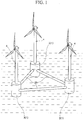
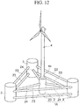
- a floating body structure 1 supports an object to be supported (superstructure 4) such as a wind turbine generator so that the superstructure 4 floats in the sea, and is provided below the superstructure 4 in association with the superstructure 4.
- the floating body structure 1 is floated in water in a state where the whole of the floating body structure 1 is sunk under water at a predetermined water depth, and at least a portion of the superstructure 4 is installed above a surface of the sea due to the buoyancy of the floating body structure 1.
- the floating body structure 1 is moored at a predetermined location in water by a mooring cable (not shown).
- the floating body structure 1 includes a floating body section 3 connected to a base end portion 4a of the superstructure 4.
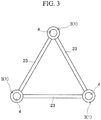
- the floating body structure 1 includes three floating body sections 3.
- the floating body structure 1 is formed in a substantially triangular planar shape with the three floating body sections 3 configured to support the three superstructures 4 as the apexes of the triangular planar shape and three floating body connecting sections 23 connecting the floating body sections 3 as three sides of the triangular planar shape.
- the floating body section 3 has a substantially cylindrical double pipe structure having a substantially cylindrical inner pipe 31 made of steel, which is provided on the inside, and a substantially cylindrical outer pipe 32 made of steel, which is provided on the outside. Further, as shown in FIGS. 4A and 4B , the floating body section 3 includes a lid body 39 made of steel.
- the floating body section 3 is hermetically sealed by the lid bodies 39 in a state where at least a portion of a gap 33 formed between the outer wall surface of the inner pipe 31 and the inner wall surface of the outer pipe 32 is filled with concrete or mortar 34. That is, each of an upper end of the floating body section 3 and a lower end of the floating body section 3 is closed by the lid body 39.
- the floating body section 3 has a hollow portion 35 formed on the inside by the inner wall surface of the inner pipe 31.
- the entirety of the gap 33 may be filled with the concrete or mortar 34. Otherwise, a configuration is also acceptable in which a portion of the gap 33 is filled with the concrete or mortar 34 and the remaining space is used as a space configured to be filled with ballast.
- a supporting member configured to support the inner pipe 31 may be provided in the gap 33 between the outer wall surface of the inner pipe 31 and the inner wall surface of the outer pipe 32.
- each of the inner pipe 31 and the outer pipe 32 is not limited to a cylindrical pipe and may be, for example, an elliptical pipe or a polygonal pipe.
- the floating body section 3 may be continuous with the superstructure 4 in a form in which the inner pipe 31 is extended.
- the inner pipe 31 may be an extended portion of the base end portion 4a of the superstructure 4.
- the base end portion 4a of the superstructure 4 may be inserted into the inside (the hollow portion 35) of the inner pipe 31.
- the inner pipe 31 and the base end portion 4a are joined to each other by filling the space between the inner pipe 31 and the base end portion 4a with the concrete or mortar 34.
- the inner pipe 31 and the base end portion 4a may be joined to each other by using bolts or welding.
- the floating body sections 3 are connected to each other by the floating body connecting section 23.
- the floating body connecting section 23 may be joined to the outer pipe 32 of the floating body section 3 by welding or bolts.
- the floating body connecting section 23 can also be stuck from the side of the floating body section 3 and then joined to the floating body section 3.
- the floating body connecting section 23 may have a double pipe structure composed of an inner pipe and an outer pipe, similar to the floating body section 3, or may have a general single pipe structure. In a case of adopting a double pipe structure as the structure of the floating body connecting section 23, at least a portion of the gap between an inner pipe and an outer pipe may be filled with concrete or mortar, in a manner similar to the floating body section 3.
- the inner pipe 31 has first joint portions 31b which join a plurality of short steel pipes 31a for inner pipe each having a predetermined length, in a longitudinal direction Z of the floating body section 3.
- the outer pipe 32 has second joint portions 32b which join a plurality of short steel pipes 32a for outer pipe each having a predetermined length, in the longitudinal direction Z.
- the first joint portion 31b and the second joint portion 32b are alternately disposed in the longitudinal direction Z.
- each of the steel pipe 31 a for inner pipe and the steel pipe 32a for outer pipe may be a bent steel pipe obtained by bending and press-forming a steel sheet into a cylindrical shape.
- each of the steel pipe 31a for inner pipe and the steel pipe 32a for outer pipe may be a spiral steel pipe obtained by press-forming a steel strip into a cylindrical shape by spirally bending the steel strip.
- the inner pipe 31 need not be configured with the plurality of steel pipes 31a for inner pipe and may be configured with a single bent steel pipe obtained by press-forming a single steel sheet into a cylindrical shape, or a single spiral steel pipe obtained by press-forming a steel strip into a cylindrical shape by spirally bending the steel strip.
- the outer pipe 32 also need not be configured with the plurality of steel pipes 32a for outer pipe and may be configured with a single bent steel pipe obtained by press-forming a single steel sheet into a cylindrical shape, or a single spiral steel pipe obtained by press-forming a steel strip into a cylindrical shape by spirally bending the steel strip.
- the position of the first joint portion 31b of the inner pipe 31 is at a steel sheet portion of the outer pipe 32 at the same position in the longitudinal direction Z
- the position of the second joint portion 32b of the outer pipe 32 is at a steel sheet portion of the inner pipe 31 at the same position in the longitudinal direction Z.
- the first joint portion 31b of the inner pipe 31 and the second joint portion 32b of the outer pipe 32 are alternately disposed in the longitudinal direction Z, and therefore, the first joint portion 31b of the inner pipe 31 and the second joint portion 32b of the outer pipe 32 are not present in the same cross section in the longitudinal direction Z.
- the floating body section 3 having such a structure, it is possible to disperse stress concentration of joint portions which would likely lower total strength if in the same cross section in the longitudinal direction Z, and as a result, it becomes possible to prevent the breakage of the floating body section 3. Further, even in a case where one of the inner pipe 31 and the outer pipe 32 is damaged, it becomes possible to secure the required structural strength of the floating body section 3 by the other of the inner pipe 31 and the outer pipe 32, which is not damaged. In this manner, the floating body section 3 has a fail-safe structure against overall breakage.
- the floating body section 3 has a double pipe structure, whereby it is possible to reduce the sheet thickness of each steel pipe which is used as the steel pipe 31a for inner pipe and the steel pipe 32a for outer pipe, and as a result, it is possible to reduce the degree of difficulty of welding in the first joint portion 31b and the second joint portion 32b. Therefore, according to the floating body structure 1 according to this embodiment, it becomes possible to use high-strength steel as the steel pipe 31a for inner pipe and the steel pipe 32a for outer pipe.
- the steel structure was configured with a relatively thin plate. For this reason, in a case where the steel structure is a rectangular structure, if water pressure acts from the side of the rectangular structure, a bending moment occurring in a steel sheet significantly increases. Even in a case where the steel structure has a circular cross-sectional shape, a large axial force acts on a steel sheet, and therefore, the sheet thickness becomes very large in order to secure structural strength against buckling.
- the filled concrete or mortar 34 not only hardly generates bending stress in order to support the steel materials of the inner pipe 31 and the outer pipe 32 from the side, but also has the effect of limiting the occurrence of buckling by restraint, thereby being structurally very reasonable.
- the concrete or mortar 34 which is filled into the gap 33 counters stress which acts on the floating body section 3 in a compression direction, it is possible to reduce structural strength in the compression direction which is required for the steel pipe 31a for inner pipe and the steel pipe 32a for outer pipe. For this reason, in the floating body structure 1 according to this embodiment, it is sufficient if the inner pipe 31 and the outer pipe 32 are designed so as to secure structural strength in a tensile direction, and thus it is possible to reduce the amount of steel which is used for the steel pipe 31a for inner pipe and the steel pipe 32a for outer pipe.
- the structural strength in the compression direction which is required for the steel pipe 31a for inner pipe and the steel pipe 32a for outer pipe is reduced, and therefore, even in a case where high-strength steel is used as the steel pipe 31a for inner pipe and the steel pipe 32a for outer pipe, it is possible to limit a reduction in buckling stress due to use of high-strength steel.
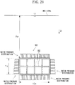
- connection buoyancy section 90 of the related art Comparing the floating body structure 1 with the connection buoyancy section 90 having a rectangular cross section of the related art shown in FIG. 20 , in the connection buoyancy section 90 of the related art, it is necessary to provide the stiffener 92 perpendicular to a wall surface inside a wall in order to secure a predetermined structural strength. For this reason, a weight of steel of, for example, 22 tons/m is required. In contrast, in the floating body structure 1 it becomes possible to secure structural strength equivalent to that of the connection buoyancy section 90 of the related art with a weight of steel of 1.2 tons/m.
- the floating body structure 1 it is possible to fabricate the floating body structure 1 with a used amount of steel of about 5%, as compared to the connection buoyancy section 90 having a rectangular cross section of the related art, and thus it becomes possible to provide a floating body type wind turbine power-generating facility at a significantly reduced manufacturing cost.
- the floating body structure 1 in a case where a spiral steel pipe is used as the steel pipe 31a for inner pipe and the steel pipe 32a for outer pipe, it is possible to use a hot coil in the manufacturing of the steel pipe. As a result, it is possible to reduce the manufacturing cost of the steel pipe, as compared to a case of using a thick steel plate. Further, it is possible to make the lengths of the steel pipe 31a for inner pipe and the steel pipe 32a for outer pipe longer, and thus it is possible to significantly reduce the number of first joint portions 31b and the second joint portions 32b or completely eliminate the first joint portion 31b and the second joint portion 32b. For this reason, according to the floating body structure 1 of this embodiment, it is possible to significantly reduce the cost required for welding.
- the floating body structure 1 according to this embodiment, welding of the inner pipe 31 and the outer pipe 32 in the longitudinal direction Z is replaced by a spiral bead.
- the spiral bead is uniformly disposed over the entire length of the steel pipe, and therefore, the spiral bead very effectively functions as a shift stop for the concrete or mortar 34 which is filled in. Therefore, according to the floating body structure 1 the structural strength of the floating body section 3 is increased and it becomes possible to provide the floating body section 3 at a reduced manufacturing cost.
- corrosion protection means may be provided on the inner wall surface of the inner pipe 31 in order to prevent corrosion by the seawater 5 or the like injected into the hollow portion 35.
- the gap 33 (the thickness of the concrete or mortar 34) between the outer wall surface of the inner pipe 31 and the inner wall surface of the outer pipe 32 is 600 mm or more, and it is preferable that at least a portion of the outer diameter of the outer pipe 32 is 6500 mm or more. This is because in a case of adopting a double pipe structure as the structure of the floating body section 3, it is realistically necessary for a worker to enter between the inner tube 31 and the outer tube 32 and perform work in a process of fabricating the floating body section 3.
- the floating body section 3 is fabricated by, for example, the following processes.
- a plurality of steel pipes 31a for inner pipe are joined in series along a vertical direction on a horizontal plane (hereinafter referred to as a working surface) which is used to perform work of fabricating the floating body section 3, whereby the inner pipe 31 which is upright with respect to the working surface is fabricated.
- a plurality of steel pipes 32a for outer pipe are joined in series along the vertical direction, whereby the outer pipe 32 which is upright with respect to the working surface and accommodates the inner pipe 31 on the inside thereof is fabricated.
- the space between the inner pipe 31 and the outer pipe 32 is filled with the concrete or mortar 34. At this time, it is necessary for a worker to enter between the inner pipe 31 and the outer pipe 32 and perform filling work.
- a longer inner pipe 31 is fabricated by joining a plurality of steel pipes 31a for inner pipe in series along the vertical direction with respect to the inner pipe 31 fabricated first. At this time, it is necessary for a worker to enter between the inner pipe 31 and the outer pipe 32 and perform joining work.
- a longer outer pipe 32 is fabricated by joining a plurality of steel pipes 32a for outer pipe in series along the vertical direction with respect to the outer pipe 32 fabricated first. Also at this time, it is necessary for a worker to enter between the inner pipe 31 and the outer pipe 32 and perform joining work. Then, the space between the inner pipe 31 and the outer pipe 32 made longer is filled with the concrete or mortar 34. As described above, a floating body section 3 having a predetermined length is fabricated by repeating the process of sequentially filling the space between the inner pipe 31 and the outer pipe 32 with the concrete or mortar 34 while gradually extending the lengths of the inner pipe 31 and the outer pipe 32.
- the gap 33 in the floating body section 3 is 600 mm or more, and it is preferable that at least a portion of the outer diameter of the outer pipe 32 is 6500 mm or more.
- the strength of the joint portion of each of the inner pipe 31 and the outer pipe 32 is reduced, and therefore, it is necessary to add reinforcement parts to the inside of the inner pipe 31 and the outside of the outer pipe 32.
- the inventor of this application calculated a sheet thickness, a generated stress, a ballast amount, and a steel weight in a case of supporting a wind turbine power-generating facility by using the floating body section 3 having a double pipe structure and a case of supporting the same wind turbine power-generating facility by using a floating body section having a general single pipe structure of the related art, by simulation.
- the calculation results are shown in Table 1.
- the weight of a section on water was set to be 550 tons such that the weight of a submerged section (including ballast) of the entire structure which includes the wind turbine power-generating facility and the floating body section became greater than or equal to ten times the weight of the section on water and the buoyancy and the total weight of the entire structure balanced each other, and the diameter of the floating body section was set to be 9 m, and the length of the floating body section was set to be 90 m.
- the reason why the weight of the submerged section is set to ten times or more the weight of the section on water is because it is the estimate of a weight ratio in which it is possible to obtain stability as a floating body.
- the above-mentioned ballast is a heavy load which is filled into an internal space of the floating body section in order to adjust the weight balance of the entire structure such that the weight of the submerged section becomes ten times or more the weight of the section on water and to make the buoyancy and the total weight of the entire structure balance each other.
- a design strength of an upper end portion of the floating body section was designed so as to be larger than a load which is generated due to a moment which is transmitted from a steel pipe, and a lower end portion of the floating body section was designed so as to be able to withstand water pressure.
- An allowable stress was set to be a value which is obtained by dividing yield strength by a safety factor of 1.5.
- a case of using SM490 as steel was assumed.
- the Young's modulus ratio of concrete and steel was set to be 7.
- the floating body structure 1 it becomes possible to provide the floating body section 3 in which structural strength capable of countering water pressure is secured without increasing the used amount of steel or the like, even in a case where the whole is sunk under water and floated in water at a predetermined water depth in order to reduce the influence of sea waves.
- the floating body structure 1A includes: a single superstructure support 2 configured to support a single superstructure 4; the three floating body sections 3 which are provided on the side of the superstructure support 2; the floating body connecting sections 23 connecting the three floating body sections 3 to each other; and support connecting sections 24 connecting the superstructure support 2 and the floating body sections 3.
- the floating body structure 1A is moored at a predetermined location in water by a mooring cable (not shown).
- the superstructure support 2 also has a double pipe structure, similar to the floating body section 3. That is, the superstructure support 2 has a structure in which the inner pipe 31 is continuous with the superstructure 4 (a structure in which the inner pipe 31 is an extended portion of the base end portion 4a of the superstructure 4) or a structure in which the base end portion 4a of the superstructure 4 is inserted into the inside (the hollow portion 35) of the inner pipe 31.
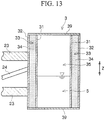
- the floating body section 3 has a substantially cylindrical double pipe structure having the substantially cylindrical inner pipe 31 made of steel, which is provided on the inside, and the substantially cylindrical outer pipe 32 made of steel, which is provided on the outside.
- the up-down direction of the floating body section 3 is the longitudinal direction Z.
- the floating body section 3 is hermetically sealed in a state where at least a portion (in FIG. 13 , the whole as an example) of the gap 33 formed between the outer wall surface of the inner pipe 31 and the inner wall surface of the outer pipe 32 is filled with the concrete or mortar 34.
- the floating body section 3 has the hollow portion 35 formed on the inside by the inner wall surface of the inner pipe 31.
- Each of the upper end of the floating body section 3 and the lower end of the floating body section 3 is closed by the lid body 39.
- the floating body structure 1A according to the second embodiment example can be sunk in water by reducing the buoyancy of the floating body structure 1A by injecting the seawater 5 or the like into the hollow portion 35 of the floating body section 3 by using injection means (not shown) in deep water where the superstructure 4 is installed.
- the floating body structure 1A of the second example as described above it is possible to secure structural strength capable of countering water pressure without increasing the used amount of steel or the like even in a case where the whole of the floating body structure 1A is sunk and floated in water at a predetermined water depth in order to reduce the influence of sea waves, and it becomes possible to obtain the buoyancy needed to float the floating body structure 1A at a predetermined water depth.
- the floating body structure 1B includes: the single superstructure support 2 configured to support the single superstructure 4; the floating body section 3 provided below the superstructure support 2; and a plurality of fins 38 which are provided on the lower side of the floating body section 3 for balancing the superstructure 4 and the floating body structure 1B in the sea.
- the floating body structure 1B is moored at a predetermined location in water by a mooring cable (not shown).
- the superstructure support 2 has a substantially cylindrical concrete block body 21.
- the base end portion 4a of the superstructure 4 is mounted in an upper end portion 2a having a substantially circular planar shape. Due to such a structure, the superstructure support 2 supports the superstructure 4.
- the floating body section 3 has a substantially cylindrical double pipe structure having the substantially cylindrical inner pipe 31 made of steel, which is provided on the inside, and the substantially cylindrical outer pipe 32 made of steel, which is provided on the outside.
- the up-down direction of the floating body section 3 is the longitudinal direction Z.
- the floating body section 3 is hermetically sealed in a state where at least a portion (in FIG. 15 , the whole as an example) of the gap 33 formed between the outer wall surface of the inner pipe 31 and the inner wall surface of the outer pipe 32 is filled with the concrete or mortar 34.
- the floating body section 3 has the hollow portion 35 formed on the inside by the inner wall surface of the inner pipe 31.
- the floating body structure 1B according to the third example can be sunk in water by reducing the buoyancy of the floating body structure 1B by injecting the seawater 5 or the like into the hollow portion 35 of the floating body section 3 by using injection means (not shown) in deep water where the superstructure 4 is installed.
- the floating body structure 1B of the third example as described above it is possible to secure structural strength capable of countering water pressure without increasing the used amount of steel or the like even in a case where the whole is sunk under water and floated in water at a predetermined water depth in order to reduce the influence of sea waves, and it becomes possible to obtain the buoyancy needed to float the floating body structure 1B at a predetermined water depth.
- the superstructure 4 in the third example may have a structure in which the superstructure 4 is continuous with the inner pipe 31 of the floating body section 3 having a double pipe structure (a structure in which the inner pipe 31 is the extended portion of the base end portion 4a of the superstructure 4).
- the superstructure 4 in the third embodiment may have a structure in which the base end portion 4a is inserted into the inside (the hollow portion 35) of the inner pipe 31 of the floating body section 3 having a double pipe structure.
- the superstructure 4 and the inner pipe 31 may be joined to each other by filling the space between the superstructure 4 and the inner pipe 31 with mortar or concrete. Otherwise, in the case of the structure shown in FIG. 16B , the superstructure 4 and the inner pipe 31 may be joined to each other by using bolts or welding.
- the floating body structure 1C includes the single floating body section 3 configured to support the single superstructure 4.
- the floating body structure 1C is moored at a predetermined location in water by a mooring cable (not shown).
- the floating body section 3 has a substantially cylindrical double pipe structure having the substantially cylindrical inner pipe 31 made of steel, which is provided on the inside, and the substantially cylindrical outer pipe 32 made of steel, which is provided on the outside.
- the up-down direction of the floating body section 3 is the longitudinal direction Z.
- the floating body section 3 is hermetically sealed in a state where at least a portion (in FIG. 18 , the whole as an example) of the gap 33 formed between the outer wall surface of the inner pipe 31 and the inner wall surface of the outer pipe 32 is filled with the concrete or mortar 34.
- the floating body section 3 has the hollow portion 35 formed on the inside by the inner wall surface of the inner pipe 31.
- the floating body structure 1C according to the fourth example can be sunk under water by reducing the buoyancy of the floating body structure 1C by injecting the seawater 5 or the like into the hollow portion 35 of the floating body section 3 by using injection means (not shown) in deep water where the superstructure 4 is installed.
- the floating body structure 1C of the fourth example as described above, it is possible to secure structural strength capable of countering water pressure without increasing the used amount of steel or the like even in a case where the whole of the floating body structure 1C is sunk under water and floated in water at a predetermined water depth in order to reduce the influence of sea waves, and it becomes possible to obtain the buoyancy needed to float the floating body structure 1C at a predetermined water depth.
- the floating body structure 1C according to the fourth example can be raised up from a state of lying sideways, by a crane or injection into the hollow portion 35.
- the floating body section 3 has very large flexural strength because of being a double pipe structure filled with the concrete or mortar 34. Further, even in a case where cracks are generated in the concrete or mortar 34 filled into the floating body section 3 while the floating body structure 1C is raised up, since the concrete or mortar 34 is completely covered with steel and does not come into direct contact with water, a durability problem does not occur.
- the superstructure 4 in the example embodiment may have a structure in which the superstructure 4 is continuous with the inner pipe 31 of the floating body section 3 having a double pipe structure (a structure in which the inner pipe 31 is the extended portion of the base end portion 4a of the superstructure 4) (refer to FIG. 16A ), similar to the third embodiment.
- the superstructure 4 in the fourth example may have a structure in which the base end portion 4a is inserted into the inside (the hollow portion 35) of the inner pipe 31 of the floating body section 3 having a double pipe structure (refer to FIG. 16B ), similar to the third embodiment.
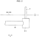
- the superstructure 4 and the floating body section 3 may not be connected such that the central axis of the superstructure 4 and the central axis of the floating body section 3 (that is, the central axis of the inner pipe 31 and the outer pipe 32) necessarily coincide with each other, as described in each of the above-described embodiments.
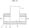
- the base end portion 4a of the superstructure 4 may penetrate toward the inside of the inner pipe 31 from the outside in the radial direction of the inner pipe 31 and the outer pipe 32.
- the superstructure 4 and the floating body section 3 may be connected to each other so that the central axis of the superstructure 4 and the central axis of the floating body section 3 are orthogonal to each other.
- the superstructure 4 may be fixed to the floating body section 3 by filling the hollow portion 35 which is formed by the inner wall surface of the inner pipe 31 with concrete or mortar 34' at a position where the base end portion 4a penetrates.
Landscapes
- Engineering & Computer Science (AREA)
- Chemical & Material Sciences (AREA)
- Combustion & Propulsion (AREA)
- Mechanical Engineering (AREA)
- Ocean & Marine Engineering (AREA)
- Physics & Mathematics (AREA)
- Fluid Mechanics (AREA)
- Civil Engineering (AREA)
- Structural Engineering (AREA)
- Architecture (AREA)
- Life Sciences & Earth Sciences (AREA)
- Sustainable Development (AREA)
- Sustainable Energy (AREA)
- General Engineering & Computer Science (AREA)
- Wind Motors (AREA)
- Revetment (AREA)
Description
- The present invention relates to a floating body structure which supports an object to be supported such as a wind turbine generator so that the object to be supported floats in the sea.
- Priority is claimed on Japanese Patent Application No.
2013-076294, filed on April 1, 2013 - Conventionally, regarding power generation methods, there are power generation by burning fossil fuels, nuclear power generation, power generation using renewable energy, and the like. Among these, in power generation by burning fossil fuels, a disadvantage that there is a concern that it may cause global warming, depletion of fossil fuels, or the like has been pointed out. Further, in nuclear power generation, it has been pointed out that when an accident occurs in a power plant, it causes an enormous amount of damage.
- In contrast, in power generation using renewable energy, there are no disadvantages related to, for example, global warming, fossil fuel depletion, and long-lasting damage after accidents, and therefore, the construction of power generation systems using renewable energy is urgently being promoted on a global scale. As power generation systems using renewable energy, wind-power generation which generates electric power by a wind turbine generator in which a blade is rotated by wind desirably includes the wind turbine generator installed in the open sea where strong wind is more reliably supplied.
- As for main methods of installing the wind turbine generator in the sea, there are a method of extending a support structure from a foundation pile driven into the seabed to the surface of the sea and installing the wind turbine generator above the support structure extending to the surface of the sea, and a method of installing the wind turbine generator above a floating body structure floated in the sea. In the open sea in which the wind turbine generator is installed, the length of the support structure becomes longer as the water depth becomes deeper, and thus the installation costs of the wind turbine generator and the like are increased, and therefore, it is difficult to adopt this method of installing the wind turbine generator above the support structure extending to the surface of the sea. Therefore, as a method of installing the wind turbine generator in the sea, it is desirable to adopt a method of installing the wind turbine generator above the floating body structure floated in the sea.
- In this manner, as a floating body type wind turbine power-generating facility in which the wind turbine generator is installed above the floating body structure floated in the sea, for example, a pontoon type floating body type wind turbine power-generating facility as disclosed in
Patent Document 1 below or a spar type floating body type wind turbine power-generating facility as disclosed inPatent Documents 2 to 4 below is proposed. -
- [Patent Document 1] Japanese Unexamined Patent Application, First Publication No.
2004-19470 - [Patent Document 2] Japanese Unexamined Patent Application, First Publication No.
2010-223113 - [Patent Document 3] Japanese Unexamined Patent Application, First Publication No.
2012-25272 - [Patent Document 4] Japanese Unexamined Patent Application, First Publication No.
2009-248792 - The technique disclosed in
Patent Document 1 is to provide a plurality of main buoyancy sections at a base end portion of a wind turbine generator and connect these main buoyancy sections by a connection buoyancy section. In the technique disclosed inPatent Document 1, the main buoyancy sections and the connection buoyancy section are floated with only lower portions thereof sunk under water. At this time, since the connection buoyancy section connects the plurality of main buoyancy sections along the surface of the sea, an area which faces sea waves is large. Further, since the main buoyancy sections and the connection buoyancy section are floated at the surface of the sea, the main buoyancy sections and the connection buoyancy section directly receive the energy of sea waves. Therefore, in the pontoon type floating body structure disclosed inPatent Document 1, there is a problem in that in a case of being installed in the open sea where the energy of sea waves is large, the entire structure easily becomes unstable due to the influence of sea waves. - Further, in the technique disclosed in
Patent Document 1, in order to reduce the influence of sea waves, a method of floating the main buoyancy sections and aconnection buoyancy section 90 with the whole sunk under water at a predetermined water depth by reducing the buoyancy of the main buoyancy sections and theconnection buoyancy section 90 is also conceivable. However, the height of the wind turbine generator sometimes reaches about 120 m above the surface of the sea, and the water depth of a location where the whole of the main buoyancy sections and theconnection buoyancy section 90 is sunk and floated in water is usually in a range of 15 m to 20 m as the height of the wind turbine generator becomes higher, and there is also a case where the maximum of the water depth exceeds 60 m. In this case, as shown inFIG. 20 , in the technique disclosed inPatent Document 1, the cross-sectional shape of theconnection buoyancy section 90 is a rectangular shape. Therefore, there is a problem that large equivalent stress is easily generated in corner portions of the rectangular cross section of theconnection buoyancy section 90 and a central portion of each side of the rectangular cross section in a case where large water pressure acts at a location where the water depth is deep. - In addition, in order to secure structural strength capable of countering the water pressure, a method of thickening walls of the main buoyancy section and the
connection buoyancy section 90, or a method of providing astiffener 92 perpendicular to a wall surface inside a wall is also conceivable. However, in these methods, there is a problem that, for example, in a case where steel is used for the wall, the amount of steel used increases, and thus the manufacturing costs of the main buoyancy section and theconnection buoyancy section 90 increase. - Further, in a case where spaces inside the walls of the main buoyancy sections and the
connection buoyancy section 90 are totally filled with concrete in order to secure structural strength capable of countering the water pressure, the weight of the main buoyancy sections and theconnection buoyancy section 90 increases, and thus there is a problem in that the buoyancy needed to float the main buoyancy sections and theconnection buoyancy section 90 at a predetermined water depth is not obtained. -
Patent Document 2 discloses a spar type floating body type wind turbine power-generating facility. A floating body section of the wind turbine power-generating facility is composed of concrete precast tubular bodies stacked in a plurality of stages in a height direction and integrated by tightly linking the respective precast tubular bodies by PC steel, and has a bottomed hollow portion having an open upper end portion. In this case, the floating body section has sufficient performance during wind-power generation operation. However, there is a problem during construction. - In stacking the precast tubular bodies and performing tight linking by the PC steel in the air, there are a case of stacking the precast tubular bodies in a longitudinal direction and a case of making the precast tubular bodies lie sideways and arranging the precast tubular bodies. In a case of stacking the precast tubular bodies in the longitudinal direction, a tower is further built on the floating body, and thus a very high crane is required, and therefore, it is difficult to cope with an increase in the size of a wind turbine. Further, in a case of making the precast tubular bodies lie sideways and of arranging the precast tubular bodies, the problem of the height of a crane is resolved. However, since the total weight of the precast tubular bodies is very heavy, a large moment acts on the floating body section when standing each of the precast tubular bodies on the floating body section. In order to secure sufficient strength against the large moment, a large amount of PC steel is required.
- In a case where cracks or the like occur in the floating body section due to insufficient flexural strength when standing each of the precast tubular bodies on the floating body section, thereafter, during wind-power generation operation, the floating body section is present in water, thereby receiving water pressure. The water pressure acts on the floating body section as horizontal prestress. However, hardly any of this effect can be expected in the vertical direction. For this reason, there is no action of closing the generated cracks, and thus the floating body section has a problem in durability or the like. That is, the technique disclosed in
Patent Document 2 is a technique having a limit with respect to an increase in the size of a structure. - The spar type floating body structure disclosed in
Patent Document 3 includes: a cylindrical column section having a peripheral surface exposed to a waterline at the time of floating; a ballast section disposed at a lower portion of the column section; and a flange section disposed at an intermediate portion of the column section. The floating body structure configured in this manner is developed for the purpose of facilitating the installation or the maintenance of the floating body structure by a working ship and is not intended to solve a durability problem associated with an increase in size. - The spar type floating body structure disclosed in
Patent Document 4 includes: a hollow lower floating body made by joining upper and lower lid bodies to a tubular precast concrete block continuously installed between the lid bodies using PC steel; a hollow upper floating body joined to the lower floating body using PC steel and composed of an upper lid and a precast concrete block having a smaller diameter than the precast concrete block described above; and a ballast tank joined to the lower surface of the lower floating body through a connecting steel pipe. - As described above, in a case where the floating body structure is configured of the PC steel, since a tensile force must not act on the surface of the concrete, a very large amount of PC steel is required. In particular, during the construction of the floating body structure, it is necessary to perform the transportation, the landing on the water, or the sinking of the floating body structure in a state where the floating body structure is lying sideways. Therefore, a very large bending moment acts on the structure configured of the heavy PC steels. In this manner, the spar type floating body structure disclosed in
Patent Document 4 is also not intended to solve the durability problem associated with an increase in size. The documentWO2012/061710 A2 describes a known floating body structure constituted of metal pipes and concrete elements. - The present invention has been made in view of the above-mentioned circumstances and has an object to provide a floating body structure in which it is possible to secure structural strength capable of countering water pressure without increasing the amount of steel or the like which is used in a wall, even in a case where the floating body stricture is floated in water with the whole of the floating body structure sunk under water at a predetermined water depth in order to reduce the influence of sea waves, and it becomes possible to obtain the buoyancy needed to float the floating body structure at a predetermined water depth, and which has a larger flexural strength.
- The present invention adopts the following measures in order to achieve the above object by solving the above-described problems.
- (1) A floating body structure according to an aspect of the present invention is a floating body structure according to
claim 1, wherein the structure supports an object to be supported so that the object to be supported floats in the sea, including a floating body section connected to a base end portion of the object to be supported, wherein the floating body section has a lid body made of steel, an outer pipe made of steel, and an inner pipe made of steel and provided inside the outer pipe, and the floating body section is hermetically sealed by the lid body in a state where at least a portion of a gap formed between an outer wall surface of the inner pipe and an inner wall surface of the outer pipe is filled with concrete or mortar. - (2) In the floating body structure according to the above (1), the inner pipe may have a first joint portion that joins a plurality of steel pipes for inner pipe each having a predetermined length along a longitudinal direction of the floating body section, the outer pipe may have a second joint portion that joins a plurality of steel pipes for outer pipe each having a predetermined length along the longitudinal direction, and the first joint portion and the second joint portion may be alternately disposed in the longitudinal direction.
- (3) In the floating body structure according to the above (2), each of the steel pipe for inner pipe and the steel pipe for outer pipe may be a spiral steel pipe obtained by press-forming a steel strip into a cylindrical shape by spirally bending the steel strip.
- (4) In the floating body structure according to the above (1), each of the inner pipe and the outer pipe may be a spiral steel pipe obtained by press-forming a steel strip into a cylindrical shape by spirally bending the steel strip.
- (5) In the floating body structure according to any one of the above (1) to (4), the base end portion of the object to be supported may penetrate toward the inside of the inner pipe from the outside in a radial direction of the inner pipe and the outer pipe and a hollow portion which is formed by an inner wall surface of the inner pipe may be filled with concrete or mortar at a position where the base end portion penetrates.
- (6) In the floating body structure according to any one of the above (1) to (5), the inner pipe may be an extended portion of the base end portion of the object to be supported.
- (7) In the floating body structure according to any one of the above (1) to (5), the base end portion of the object to be supported may be inserted into the inner pipe and a hollow portion which is formed by an inner wall surface of the inner pipe may be filled with concrete or mortar at a position where the base end portion is inserted.
- (8) The floating body structure according to any one of the above (1) to (7), a plurality of the floating body sections may be provided and the plurality of floating body sections may be connected to each other by a floating body connecting section.
- (9) In the floating body structure according to any one of the above (1) to (8), the gap between the outer wall surface of the inner pipe and the inner wall surface of the outer pipe may be 600 mm or more, and at least a portion of an outer diameter of the outer pipe may be 6500 mm or more.
- According to the floating body structure according to the aspect of the above (1), it is possible to secure structural strength capable of countering water pressure without increasing the amount of steel or the like which is used in a wall, even in a case where the floating body structure is floated in water with the whole sunk under water at a predetermined water depth in order to reduce the influence of sea waves, and it becomes possible to obtain the buoyancy needed to float the floating body structure at a predetermined water depth. In addition, it becomes possible to secure sufficient flexural strength.
- In particular, according to the floating body structure according to the aspect of the above (2), the position of the first joint portion of the inner pipe is at a steel sheet portion of the outer pipe at the same position in the longitudinal direction and the position of the second joint portion of the outer pipe is at a steel sheet portion of the inner pipe at the same position in the longitudinal direction, and thus a configuration is made in which the first joint portion of the inner pipe and the second joint portion of the outer pipe are not present in the same cross section in the longitudinal direction. Due to this, it is possible to disperse joint portions which would likely lower total strength if in the same cross section, and thus it becomes possible to prevent the breakage of the floating body section having a double pipe structure.
- In particular, according to the floating body structure according to the aspect of the above (3), welding of the inner pipe and the outer pipe in the longitudinal direction is replaced by a spiral bead. Welding of the spiral bead is welding automated in a factory, and therefore, it becomes possible to provide a floating body section having a double pipe structure with a reduced manufacturing cost. In addition, the spiral bead acts as a shift stop, and therefore, the spiral bead contributes to the combining of internal concrete and a steel pipe portion, and thus it becomes possible to obtain higher structural strength.
-
-
FIG. 1 is a perspective view schematically showing the configuration of a floating body type wind turbine power-generating facility provided with a floating body structure according to an example. -
FIG. 2 is a side view showing the floating body structure according tofigure 1 . -
FIG. 3 is a plan view showing the floating body structure according tofigure 1 .
The followingfigures 4A, 4B ,5A, 5B ,6 to 9 ,10A ,10B and11 also describe examples which do not form part of the claimed invention. -
FIG. 4A is a longitudinal cross-sectional side view showing a state where a superstructure (an object to be supported) is mounted on a floating body section (a diagram showing a case where an inner pipe is continuous with the superstructure), with regard to the floating body structure according to an example. -
FIG. 4B is a longitudinal cross-sectional side view showing a state where the superstructure (the object to be supported) is mounted on the floating body section (a diagram showing a case where the superstructure is inserted into the inner pipe), with regard to the floating body structure. -
FIG. 5A is a transverse cross-sectional plan view showing a state where the superstructure is mounted on the floating body section (a diagram showing a case where the inner pipe is continuous with the superstructure), with regard to the floating body structure. -
FIG. 5B is a transverse cross-sectional side view showing a state where the superstructure (the object to be supported) is mounted on the floating body section (a diagram showing a case where the superstructure is inserted into the inner pipe), with regard to the floating body structure. -
FIG. 6 is a longitudinal cross-sectional view of the floating body section of the floating body structure. -
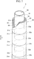
FIG. 7 is a perspective view, in a partial cut away, showing an aspect in which a bent steel pipe is used for the inner pipe and an outer pipe, with regard to the floating body structure. -
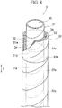
FIG. 8 is a perspective view, in a partial cut away, showing an aspect in which a spiral steel pipe is used for the inner pipe and the outer pipe, with regard to the floating body structure. -
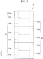
FIG. 9 is a side view of the floating body. -
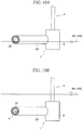
FIG. 10A is an explanatory diagram showing a state before the floating body structure sinks under water. -
FIG. 10B is an explanatory diagram showing a state where the floating body structure has sunk under water. -
FIG. 11 is a schematic diagram showing a 2.5 MW-grade wind turbine power-generating facility assumed as an object to be supported in simulation. -
FIG. 12 is a perspective view schematically showing the configuration of a floating body type wind turbine power-generating facility provided with a floating body structure according to a second example. -
FIG. 13 is a longitudinal cross-sectional side view showing a floating body section of the floating body structure according to the second example. -
FIG. 14 is a perspective view schematically showing the configuration of a floating body type wind turbine power-generating facility provided with a floating body structure according to a third example. -
FIG. 15 is a longitudinal cross-sectional side view showing a state where a superstructure support which supports a superstructure is mounted on a floating body section, with regard to the floating body structure according to the third example. -
FIG. 16A is a longitudinal cross-sectional side view showing a state where the superstructure is mounted on the floating body section (a diagram showing a case where the inner pipe is continuous with the superstructure), with regard to the floating body structure according to the third example. -
FIG. 16B is a longitudinal cross-sectional side view showing a state where the superstructure is mounted on the floating body section (a diagram showing a case where the superstructure is inserted into the inner pipe), with regard to the floating body structure according to the third example. -
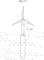
FIG. 17 is a perspective view schematically showing the configuration of a floating body type wind turbine power-generating facility provided with a floating body structure according to a fourth example. -
FIG. 18 is a longitudinal cross-sectional side view showing a state where the superstructure is mounted on a floating body section, with regard to the floating body structure according to the fourth example. -
FIG. 19 is an explanatory diagram showing the embodiment of the present invention where a base end portion of the superstructure penetrates toward the inside of the inner pipe from the outside in a radial direction of the inner pipe and the outer pipe. -
FIG. 20 is a distribution diagram of water pressure acting on a connection buoyancy section having a rectangular cross section in the related art. - Hereinafter, floating body structures according to embodiments of the present invention will be described in detail with reference to the drawings.
- As shown in
FIGS. 1 and2 , a floatingbody structure 1 supports an object to be supported (superstructure 4) such as a wind turbine generator so that thesuperstructure 4 floats in the sea, and is provided below thesuperstructure 4 in association with thesuperstructure 4. The floatingbody structure 1 is floated in water in a state where the whole of the floatingbody structure 1 is sunk under water at a predetermined water depth, and at least a portion of thesuperstructure 4 is installed above a surface of the sea due to the buoyancy of the floatingbody structure 1. The floatingbody structure 1 is moored at a predetermined location in water by a mooring cable (not shown). - The floating
body structure 1 includes a floatingbody section 3 connected to abase end portion 4a of thesuperstructure 4. For example, in a case where there are threesuperstructures 4, as shown inFIGS. 1 and3 , the floatingbody structure 1 includes three floatingbody sections 3. In this case, the floatingbody structure 1 is formed in a substantially triangular planar shape with the three floatingbody sections 3 configured to support the threesuperstructures 4 as the apexes of the triangular planar shape and three floatingbody connecting sections 23 connecting the floatingbody sections 3 as three sides of the triangular planar shape. - As shown in
FIG. 6 , the floatingbody section 3 has a substantially cylindrical double pipe structure having a substantially cylindricalinner pipe 31 made of steel, which is provided on the inside, and a substantially cylindricalouter pipe 32 made of steel, which is provided on the outside. Further, as shown inFIGS. 4A and 4B , the floatingbody section 3 includes alid body 39 made of steel. The floatingbody section 3 is hermetically sealed by thelid bodies 39 in a state where at least a portion of agap 33 formed between the outer wall surface of theinner pipe 31 and the inner wall surface of theouter pipe 32 is filled with concrete ormortar 34. That is, each of an upper end of the floatingbody section 3 and a lower end of the floatingbody section 3 is closed by thelid body 39. The floatingbody section 3 has ahollow portion 35 formed on the inside by the inner wall surface of theinner pipe 31. - In addition, the entirety of the
gap 33 may be filled with the concrete ormortar 34. Otherwise, a configuration is also acceptable in which a portion of thegap 33 is filled with the concrete ormortar 34 and the remaining space is used as a space configured to be filled with ballast. Further, a supporting member configured to support theinner pipe 31 may be provided in thegap 33 between the outer wall surface of theinner pipe 31 and the inner wall surface of theouter pipe 32. In addition, each of theinner pipe 31 and theouter pipe 32 is not limited to a cylindrical pipe and may be, for example, an elliptical pipe or a polygonal pipe. - As shown in
FIGS. 4A and5A , the floatingbody section 3 may be continuous with thesuperstructure 4 in a form in which theinner pipe 31 is extended. In other words, theinner pipe 31 may be an extended portion of thebase end portion 4a of thesuperstructure 4. - Further, as shown in
FIGS. 4B and5B , thebase end portion 4a of thesuperstructure 4 may be inserted into the inside (the hollow portion 35) of theinner pipe 31. In this case, as shown inFIG. 4B , theinner pipe 31 and thebase end portion 4a are joined to each other by filling the space between theinner pipe 31 and thebase end portion 4a with the concrete ormortar 34. However, theinner pipe 31 and thebase end portion 4a may be joined to each other by using bolts or welding. In a case where theinner pipe 31 and thebase end portion 4a are joined to each other by filling the space between theinner pipe 31 and thebase end portion 4a with the concrete ormortar 34, a stud, a weld bead, or the like is disposed on the steel surface which contacts with the concrete ormortar 34 as a shift stop, whereby it is possible to shorten the length of a joint portion. - The floating
body sections 3 are connected to each other by the floatingbody connecting section 23. However, the floatingbody connecting section 23 may be joined to theouter pipe 32 of the floatingbody section 3 by welding or bolts. Further, as shown inFIGS. 4A, 4B ,5A, and 5B , the floatingbody connecting section 23 can also be stuck from the side of the floatingbody section 3 and then joined to the floatingbody section 3. In addition, the floatingbody connecting section 23 may have a double pipe structure composed of an inner pipe and an outer pipe, similar to the floatingbody section 3, or may have a general single pipe structure. In a case of adopting a double pipe structure as the structure of the floatingbody connecting section 23, at least a portion of the gap between an inner pipe and an outer pipe may be filled with concrete or mortar, in a manner similar to the floatingbody section 3. - As shown in
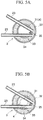
FIGS. 7 and8 , theinner pipe 31 has firstjoint portions 31b which join a plurality ofshort steel pipes 31a for inner pipe each having a predetermined length, in a longitudinal direction Z of the floatingbody section 3. As shown inFIGS. 7 and8 , theouter pipe 32 has secondjoint portions 32b which join a plurality ofshort steel pipes 32a for outer pipe each having a predetermined length, in the longitudinal direction Z. As shown inFIG. 9 , the firstjoint portion 31b and the secondjoint portion 32b are alternately disposed in the longitudinal direction Z. - As shown in
FIG. 7 , each of thesteel pipe 31 a for inner pipe and thesteel pipe 32a for outer pipe may be a bent steel pipe obtained by bending and press-forming a steel sheet into a cylindrical shape. Otherwise, as shown inFIG. 8 , each of thesteel pipe 31a for inner pipe and thesteel pipe 32a for outer pipe may be a spiral steel pipe obtained by press-forming a steel strip into a cylindrical shape by spirally bending the steel strip. - In addition, the
inner pipe 31 need not be configured with the plurality ofsteel pipes 31a for inner pipe and may be configured with a single bent steel pipe obtained by press-forming a single steel sheet into a cylindrical shape, or a single spiral steel pipe obtained by press-forming a steel strip into a cylindrical shape by spirally bending the steel strip. Similarly, theouter pipe 32 also need not be configured with the plurality ofsteel pipes 32a for outer pipe and may be configured with a single bent steel pipe obtained by press-forming a single steel sheet into a cylindrical shape, or a single spiral steel pipe obtained by press-forming a steel strip into a cylindrical shape by spirally bending the steel strip. - In the floating
body structure 1 the position of the firstjoint portion 31b of theinner pipe 31 is at a steel sheet portion of theouter pipe 32 at the same position in the longitudinal direction Z, and the position of the secondjoint portion 32b of theouter pipe 32 is at a steel sheet portion of theinner pipe 31 at the same position in the longitudinal direction Z. In this manner, the firstjoint portion 31b of theinner pipe 31 and the secondjoint portion 32b of theouter pipe 32 are alternately disposed in the longitudinal direction Z, and therefore, the firstjoint portion 31b of theinner pipe 31 and the secondjoint portion 32b of theouter pipe 32 are not present in the same cross section in the longitudinal direction Z. According to the floatingbody section 3 having such a structure, it is possible to disperse stress concentration of joint portions which would likely lower total strength if in the same cross section in the longitudinal direction Z, and as a result, it becomes possible to prevent the breakage of the floatingbody section 3. Further, even in a case where one of theinner pipe 31 and theouter pipe 32 is damaged, it becomes possible to secure the required structural strength of the floatingbody section 3 by the other of theinner pipe 31 and theouter pipe 32, which is not damaged. In this manner, the floatingbody section 3 has a fail-safe structure against overall breakage. - In the floating
body structure 1 the floatingbody section 3 has a double pipe structure, whereby it is possible to reduce the sheet thickness of each steel pipe which is used as thesteel pipe 31a for inner pipe and thesteel pipe 32a for outer pipe, and as a result, it is possible to reduce the degree of difficulty of welding in the firstjoint portion 31b and the secondjoint portion 32b. Therefore, according to the floatingbody structure 1 according to this embodiment, it becomes possible to use high-strength steel as thesteel pipe 31a for inner pipe and thesteel pipe 32a for outer pipe. - Originally, in a case where a structure which is sunk under water was formed with a steel structure, the steel structure was configured with a relatively thin plate. For this reason, in a case where the steel structure is a rectangular structure, if water pressure acts from the side of the rectangular structure, a bending moment occurring in a steel sheet significantly increases. Even in a case where the steel structure has a circular cross-sectional shape, a large axial force acts on a steel sheet, and therefore, the sheet thickness becomes very large in order to secure structural strength against buckling.
- However, in a case where the double pipe structure in which the
gap 33 between theinner pipe 31 and theouter pipe 32 is filled with the concrete ormortar 34 or the like is adopted as the structure of the floatingbody section 3, water pressure generates a compressive force in the concrete ormortar 34. However, the compressive force acts as prestress, and therefore, the strength of the concrete ormortar 34 working as a structure is significantly improved. - In addition, the filled concrete or
mortar 34 not only hardly generates bending stress in order to support the steel materials of theinner pipe 31 and theouter pipe 32 from the side, but also has the effect of limiting the occurrence of buckling by restraint, thereby being structurally very reasonable. - In the floating
body structure 1 since the concrete ormortar 34 which is filled into thegap 33 counters stress which acts on the floatingbody section 3 in a compression direction, it is possible to reduce structural strength in the compression direction which is required for thesteel pipe 31a for inner pipe and thesteel pipe 32a for outer pipe. For this reason, in the floatingbody structure 1 according to this embodiment, it is sufficient if theinner pipe 31 and theouter pipe 32 are designed so as to secure structural strength in a tensile direction, and thus it is possible to reduce the amount of steel which is used for thesteel pipe 31a for inner pipe and thesteel pipe 32a for outer pipe. Further, in the floatingbody structure 1 according to this embodiment, the structural strength in the compression direction which is required for thesteel pipe 31a for inner pipe and thesteel pipe 32a for outer pipe is reduced, and therefore, even in a case where high-strength steel is used as thesteel pipe 31a for inner pipe and thesteel pipe 32a for outer pipe, it is possible to limit a reduction in buckling stress due to use of high-strength steel. - Comparing the floating
body structure 1 with theconnection buoyancy section 90 having a rectangular cross section of the related art shown inFIG. 20 , in theconnection buoyancy section 90 of the related art, it is necessary to provide thestiffener 92 perpendicular to a wall surface inside a wall in order to secure a predetermined structural strength. For this reason, a weight of steel of, for example, 22 tons/m is required. In contrast, in the floatingbody structure 1 it becomes possible to secure structural strength equivalent to that of theconnection buoyancy section 90 of the related art with a weight of steel of 1.2 tons/m. For this reason, according to the floatingbody structure 1 according to this embodiment, it is possible to fabricate the floatingbody structure 1 with a used amount of steel of about 5%, as compared to theconnection buoyancy section 90 having a rectangular cross section of the related art, and thus it becomes possible to provide a floating body type wind turbine power-generating facility at a significantly reduced manufacturing cost. - According to the floating
body structure 1 in a case where a spiral steel pipe is used as thesteel pipe 31a for inner pipe and thesteel pipe 32a for outer pipe, it is possible to use a hot coil in the manufacturing of the steel pipe. As a result, it is possible to reduce the manufacturing cost of the steel pipe, as compared to a case of using a thick steel plate. Further, it is possible to make the lengths of thesteel pipe 31a for inner pipe and thesteel pipe 32a for outer pipe longer, and thus it is possible to significantly reduce the number of firstjoint portions 31b and the secondjoint portions 32b or completely eliminate the firstjoint portion 31b and the secondjoint portion 32b. For this reason, according to the floatingbody structure 1 of this embodiment, it is possible to significantly reduce the cost required for welding. In addition, according to the floatingbody structure 1 according to this embodiment, welding of theinner pipe 31 and theouter pipe 32 in the longitudinal direction Z is replaced by a spiral bead. The spiral bead is uniformly disposed over the entire length of the steel pipe, and therefore, the spiral bead very effectively functions as a shift stop for the concrete ormortar 34 which is filled in. Therefore, according to the floatingbody structure 1 the structural strength of the floatingbody section 3 is increased and it becomes possible to provide the floatingbody section 3 at a reduced manufacturing cost. - As shown in
FIG. 10A , in the floatingbody structure 1 by increasing the buoyancy of the floatingbody structure 1 by making thehollow portion 35 be in a hollow state, it is possible to tow the floatingbody structure 1 from the coast to deep water in a state where the floatingbody structure 1 is floated on the surface of the sea. - Further, as shown in
FIG. 10B , in the floatingbody structure 1 by reducing the buoyancy of the floatingbody structure 1 by injectingseawater 5 or the like into thehollow portion 35 by using injection means (not shown) in deep water where thesuperstructure 4 is installed, it is possible to float the whole of the floatingbody structure 1 in water with it sunk under water at a predetermined water depth. - In addition, in the floating
body structure 1 since thehollow portion 35 is formed and the inside of the floatingbody section 3 is not totally filled with concrete or the like, it becomes possible to obtain the buoyancy needed to float the floatingbody structure 1 at a predetermined water depth. In addition, according to the floatingbody structure 1 according to this embodiment, corrosion protection means (not shown) may be provided on the inner wall surface of theinner pipe 31 in order to prevent corrosion by theseawater 5 or the like injected into thehollow portion 35. - Further, it is also effective to inject powder or a fluid material such as slag, or a fluid solidified material such as mortar or concrete, instead of seawater, into the
hollow portion 35 of theinner pipe 31. - In the floating
body section 3, it is preferable that the gap 33 (the thickness of the concrete or mortar 34) between the outer wall surface of theinner pipe 31 and the inner wall surface of theouter pipe 32 is 600 mm or more, and it is preferable that at least a portion of the outer diameter of theouter pipe 32 is 6500 mm or more. This is because in a case of adopting a double pipe structure as the structure of the floatingbody section 3, it is realistically necessary for a worker to enter between theinner tube 31 and theouter tube 32 and perform work in a process of fabricating the floatingbody section 3. - Specifically, the floating
body section 3 is fabricated by, for example, the following processes. - First, a plurality of
steel pipes 31a for inner pipe are joined in series along a vertical direction on a horizontal plane (hereinafter referred to as a working surface) which is used to perform work of fabricating the floatingbody section 3, whereby theinner pipe 31 which is upright with respect to the working surface is fabricated. Subsequently, a plurality ofsteel pipes 32a for outer pipe are joined in series along the vertical direction, whereby theouter pipe 32 which is upright with respect to the working surface and accommodates theinner pipe 31 on the inside thereof is fabricated. - Subsequently, the space between the
inner pipe 31 and theouter pipe 32 is filled with the concrete ormortar 34. At this time, it is necessary for a worker to enter between theinner pipe 31 and theouter pipe 32 and perform filling work. Subsequently, a longerinner pipe 31 is fabricated by joining a plurality ofsteel pipes 31a for inner pipe in series along the vertical direction with respect to theinner pipe 31 fabricated first. At this time, it is necessary for a worker to enter between theinner pipe 31 and theouter pipe 32 and perform joining work. - Subsequently, a longer
outer pipe 32 is fabricated by joining a plurality ofsteel pipes 32a for outer pipe in series along the vertical direction with respect to theouter pipe 32 fabricated first. Also at this time, it is necessary for a worker to enter between theinner pipe 31 and theouter pipe 32 and perform joining work. Then, the space between theinner pipe 31 and theouter pipe 32 made longer is filled with the concrete ormortar 34. As described above, a floatingbody section 3 having a predetermined length is fabricated by repeating the process of sequentially filling the space between theinner pipe 31 and theouter pipe 32 with the concrete ormortar 34 while gradually extending the lengths of theinner pipe 31 and theouter pipe 32. - In this manner, it is necessary for a worker to enter between the
inner pipe 31 and theouter pipe 32 and perform work in the process of fabricating the floatingbody section 3, and therefore, it is preferable that thegap 33 in the floatingbody section 3 is 600 mm or more, and it is preferable that at least a portion of the outer diameter of theouter pipe 32 is 6500 mm or more. On the other hand, in a case of using dimensions less than the above-described dimensions, the strength of the joint portion of each of theinner pipe 31 and theouter pipe 32 is reduced, and therefore, it is necessary to add reinforcement parts to the inside of theinner pipe 31 and the outside of theouter pipe 32. However, it is not preferable to install the reinforcement parts on the outside of theouter pipe 32 in terms of external appearance and corrosion protection. - The inventor of this application calculated a sheet thickness, a generated stress, a ballast amount, and a steel weight in a case of supporting a wind turbine power-generating facility by using the floating
body section 3 having a double pipe structure and a case of supporting the same wind turbine power-generating facility by using a floating body section having a general single pipe structure of the related art, by simulation. The calculation results are shown in Table 1. - In addition, as shown in
FIG. 11 , in the simulation, a 2.5 MW-grade wind turbine power-generating facility was assumed as an object to be supported. Further, in the simulation, the weight of a section on water was set to be 550 tons such that the weight of a submerged section (including ballast) of the entire structure which includes the wind turbine power-generating facility and the floating body section became greater than or equal to ten times the weight of the section on water and the buoyancy and the total weight of the entire structure balanced each other, and the diameter of the floating body section was set to be 9 m, and the length of the floating body section was set to be 90 m. In addition, the reason why the weight of the submerged section is set to ten times or more the weight of the section on water is because it is the estimate of a weight ratio in which it is possible to obtain stability as a floating body. Here, the above-mentioned ballast is a heavy load which is filled into an internal space of the floating body section in order to adjust the weight balance of the entire structure such that the weight of the submerged section becomes ten times or more the weight of the section on water and to make the buoyancy and the total weight of the entire structure balance each other. - Further, in the simulation, a design strength of an upper end portion of the floating body section was designed so as to be larger than a load which is generated due to a moment which is transmitted from a steel pipe, and a lower end portion of the floating body section was designed so as to be able to withstand water pressure. An allowable stress was set to be a value which is obtained by dividing yield strength by a safety factor of 1.5. A case of using SM490 as steel was assumed. The Young's modulus ratio of concrete and steel was set to be 7.
[Table 1] Single pipe structure Double pipe structure Sheet thickness 25 mm steel: each of outer pipe and inner pipe: 6 mm concrete: 700 mm Generated stress 176 MPa steel: 22 MPa concrete: 3 MPa Amount of ballast 3335 tons 995 tons Steel weight 500 tons in only outer wall skin plate. 1000 tons if the steel weight of a stiffening structure, a bulkhead, and the like is added. 224 tons (including bottom plate of 6 mm) Evaluation The amount of ballast is very large and the weight is insufficient. Since the thickness of 25 mm is relatively thin with respect to the outer diameter of 9 m, it is necessary to provide stiffeners in a single pipe at a high density. Since the generated stress is very small, almost no increase in sheet thickness is required even with a further increase in size. - As shown in Table 1, in a case of supporting the 2.5 MW-grade wind turbine power-generating facility by using the floating body section having the general single pipe structure of the related art, it was found that the amount of ballast was very large and the weight was insufficient. Further, in a case where the diameter of the floating body section was 9 m, the sheet thickness was 25 mm, and therefore, it was found that in order to obtain the necessary structural strength, it was necessary to provide stiffeners in the single pipe at a high density.
- In contrast, in a case of supporting the 2.5 MW-grade wind turbine power-generating facility by using the floating
body section 3 having the double pipe structure, since the generated stress was very small, it was found that almost no increase in sheet thickness was required even with a further increase in size and the necessary structural strength was obtained. - As described above, according to the floating
body structure 1 it becomes possible to provide the floatingbody section 3 in which structural strength capable of countering water pressure is secured without increasing the used amount of steel or the like, even in a case where the whole is sunk under water and floated in water at a predetermined water depth in order to reduce the influence of sea waves. - Next, a floating
body structure 1A according to a second example will be described in detail with reference to the drawings. In addition, in the following second embodiment, the same constituent elements as the constituent elements in the first embodiment described above are denoted by the same reference numerals, and a description thereof is omitted below. - As shown in
FIG. 12 , for example, the floatingbody structure 1A according to the second example includes: asingle superstructure support 2 configured to support asingle superstructure 4; the three floatingbody sections 3 which are provided on the side of thesuperstructure support 2; the floatingbody connecting sections 23 connecting the three floatingbody sections 3 to each other; andsupport connecting sections 24 connecting thesuperstructure support 2 and the floatingbody sections 3. The floatingbody structure 1A is moored at a predetermined location in water by a mooring cable (not shown). - The
superstructure support 2 also has a double pipe structure, similar to the floatingbody section 3. That is, thesuperstructure support 2 has a structure in which theinner pipe 31 is continuous with the superstructure 4 (a structure in which theinner pipe 31 is an extended portion of thebase end portion 4a of the superstructure 4) or a structure in which thebase end portion 4a of thesuperstructure 4 is inserted into the inside (the hollow portion 35) of theinner pipe 31. - As shown in
FIG. 13 , the floatingbody section 3 has a substantially cylindrical double pipe structure having the substantially cylindricalinner pipe 31 made of steel, which is provided on the inside, and the substantially cylindricalouter pipe 32 made of steel, which is provided on the outside. The up-down direction of the floatingbody section 3 is the longitudinal direction Z. The floatingbody section 3 is hermetically sealed in a state where at least a portion (inFIG. 13 , the whole as an example) of thegap 33 formed between the outer wall surface of theinner pipe 31 and the inner wall surface of theouter pipe 32 is filled with the concrete ormortar 34. The floatingbody section 3 has thehollow portion 35 formed on the inside by the inner wall surface of theinner pipe 31. Each of the upper end of the floatingbody section 3 and the lower end of the floatingbody section 3 is closed by thelid body 39. - As shown in
FIG. 13 , the floatingbody structure 1A according to the second embodiment example can be sunk in water by reducing the buoyancy of the floatingbody structure 1A by injecting theseawater 5 or the like into thehollow portion 35 of the floatingbody section 3 by using injection means (not shown) in deep water where thesuperstructure 4 is installed. - According to the floating
body structure 1A of the second example as described above, it is possible to secure structural strength capable of countering water pressure without increasing the used amount of steel or the like even in a case where the whole of the floatingbody structure 1A is sunk and floated in water at a predetermined water depth in order to reduce the influence of sea waves, and it becomes possible to obtain the buoyancy needed to float the floatingbody structure 1A at a predetermined water depth. - Next, a floating
body structure 1B according to a third example will be described in detail with reference to the drawings. In addition, in the following third embodiment, the same constituent elements as the constituent elements in the first and second embodiments described above are denoted by the same reference numerals, and a description thereof is omitted below. - As shown in
FIG. 14 , for example, the floatingbody structure 1B includes: thesingle superstructure support 2 configured to support thesingle superstructure 4; the floatingbody section 3 provided below thesuperstructure support 2; and a plurality offins 38 which are provided on the lower side of the floatingbody section 3 for balancing thesuperstructure 4 and the floatingbody structure 1B in the sea. The floatingbody structure 1B is moored at a predetermined location in water by a mooring cable (not shown). - As shown in
FIG. 15 , thesuperstructure support 2 has a substantially cylindricalconcrete block body 21. In thesuperstructure support 2, thebase end portion 4a of thesuperstructure 4 is mounted in anupper end portion 2a having a substantially circular planar shape. Due to such a structure, thesuperstructure support 2 supports thesuperstructure 4. - As shown in
FIG. 15 , the floatingbody section 3 has a substantially cylindrical double pipe structure having the substantially cylindricalinner pipe 31 made of steel, which is provided on the inside, and the substantially cylindricalouter pipe 32 made of steel, which is provided on the outside. The up-down direction of the floatingbody section 3 is the longitudinal direction Z. The floatingbody section 3 is hermetically sealed in a state where at least a portion (inFIG. 15 , the whole as an example) of thegap 33 formed between the outer wall surface of theinner pipe 31 and the inner wall surface of theouter pipe 32 is filled with the concrete ormortar 34. The floatingbody section 3 has thehollow portion 35 formed on the inside by the inner wall surface of theinner pipe 31. - As shown in
FIG. 15 , the floatingbody structure 1B according to the third example can be sunk in water by reducing the buoyancy of the floatingbody structure 1B by injecting theseawater 5 or the like into thehollow portion 35 of the floatingbody section 3 by using injection means (not shown) in deep water where thesuperstructure 4 is installed. - According to the floating
body structure 1B of the third example as described above, it is possible to secure structural strength capable of countering water pressure without increasing the used amount of steel or the like even in a case where the whole is sunk under water and floated in water at a predetermined water depth in order to reduce the influence of sea waves, and it becomes possible to obtain the buoyancy needed to float the floatingbody structure 1B at a predetermined water depth. - In addition, as shown in
FIG. 16A , thesuperstructure 4 in the third example may have a structure in which thesuperstructure 4 is continuous with theinner pipe 31 of the floatingbody section 3 having a double pipe structure (a structure in which theinner pipe 31 is the extended portion of thebase end portion 4a of the superstructure 4). Further, as shown inFIG. 16B , thesuperstructure 4 in the third embodiment may have a structure in which thebase end portion 4a is inserted into the inside (the hollow portion 35) of theinner pipe 31 of the floatingbody section 3 having a double pipe structure. In the case of the structure shown inFIG. 16B , thesuperstructure 4 and theinner pipe 31 may be joined to each other by filling the space between thesuperstructure 4 and theinner pipe 31 with mortar or concrete. Otherwise, in the case of the structure shown inFIG. 16B , thesuperstructure 4 and theinner pipe 31 may be joined to each other by using bolts or welding. - Next, a floating
body structure 1C according to a fourth embodiment of the present invention will be described in detail with reference to the drawings. In addition, in the following fourth embodiment, the same constituent elements as the constituent elements in the first to third embodiments described above are denoted by the same reference numerals, and a description thereof is omitted below. - As shown in
FIG. 17 , for example, the floatingbody structure 1C according to the fourth example includes the single floatingbody section 3 configured to support thesingle superstructure 4. The floatingbody structure 1C is moored at a predetermined location in water by a mooring cable (not shown). - As shown in
FIG. 18 , the floatingbody section 3 has a substantially cylindrical double pipe structure having the substantially cylindricalinner pipe 31 made of steel, which is provided on the inside, and the substantially cylindricalouter pipe 32 made of steel, which is provided on the outside. The up-down direction of the floatingbody section 3 is the longitudinal direction Z. The floatingbody section 3 is hermetically sealed in a state where at least a portion (inFIG. 18 , the whole as an example) of thegap 33 formed between the outer wall surface of theinner pipe 31 and the inner wall surface of theouter pipe 32 is filled with the concrete ormortar 34. The floatingbody section 3 has thehollow portion 35 formed on the inside by the inner wall surface of theinner pipe 31. - As shown in
FIG. 18 , the floatingbody structure 1C according to the fourth example can be sunk under water by reducing the buoyancy of the floatingbody structure 1C by injecting theseawater 5 or the like into thehollow portion 35 of the floatingbody section 3 by using injection means (not shown) in deep water where thesuperstructure 4 is installed. - According to the floating
body structure 1C of the fourth example as described above, it is possible to secure structural strength capable of countering water pressure without increasing the used amount of steel or the like even in a case where the whole of the floatingbody structure 1C is sunk under water and floated in water at a predetermined water depth in order to reduce the influence of sea waves, and it becomes possible to obtain the buoyancy needed to float the floatingbody structure 1C at a predetermined water depth. - Further, the floating
body structure 1C according to the fourth example can be raised up from a state of lying sideways, by a crane or injection into thehollow portion 35. The floatingbody section 3 has very large flexural strength because of being a double pipe structure filled with the concrete ormortar 34. Further, even in a case where cracks are generated in the concrete ormortar 34 filled into the floatingbody section 3 while the floatingbody structure 1C is raised up, since the concrete ormortar 34 is completely covered with steel and does not come into direct contact with water, a durability problem does not occur. - In addition, the
superstructure 4 in the example embodiment may have a structure in which thesuperstructure 4 is continuous with theinner pipe 31 of the floatingbody section 3 having a double pipe structure (a structure in which theinner pipe 31 is the extended portion of thebase end portion 4a of the superstructure 4) (refer toFIG. 16A ), similar to the third embodiment. Further, thesuperstructure 4 in the fourth example may have a structure in which thebase end portion 4a is inserted into the inside (the hollow portion 35) of theinner pipe 31 of the floatingbody section 3 having a double pipe structure (refer toFIG. 16B ), similar to the third embodiment. - The first to fourth examples have been described above. However, the
superstructure 4 and the floatingbody section 3 may not be connected such that the central axis of thesuperstructure 4 and the central axis of the floating body section 3 (that is, the central axis of theinner pipe 31 and the outer pipe 32) necessarily coincide with each other, as described in each of the above-described embodiments. - According with the present invention, as shown in
FIG. 19 , thebase end portion 4a of thesuperstructure 4 may penetrate toward the inside of theinner pipe 31 from the outside in the radial direction of theinner pipe 31 and theouter pipe 32. In other words, thesuperstructure 4 and the floatingbody section 3 may be connected to each other so that the central axis of thesuperstructure 4 and the central axis of the floatingbody section 3 are orthogonal to each other. As shown inFIG. 19 , thesuperstructure 4 may be fixed to the floatingbody section 3 by filling thehollow portion 35 which is formed by the inner wall surface of theinner pipe 31 with concrete or mortar 34' at a position where thebase end portion 4a penetrates. - The present invention have been described above in detail. However, all examples described above merely help understand how the present invention is carried out, and the technical scope of the present invention is defined by the claims.
-
- 1, 1A, 1B, 1C: floating body structure
- 2: superstructure support
- 2a: upper end portion of superstructure support
- 21: block body
- 23: floating body connecting section
- 24: support connecting section
- 3: floating body section
- 31: inner pipe
- 31a: steel pipe for inner pipe
- 31b: first joint portion
- 32: outer pipe
- 32a: steel pipe for outer pipe
- 32b: second joint portion
- 33: gap
- 34: concrete or mortar
- 35: hollow portion
- 38: fin
- 39: lid body
- 4: superstructure
- 4a: base end portion of superstructure
- 5: seawater
- 90: connection buoyancy section
- Z: longitudinal direction
Claims (7)
- A floating body structure (1) that is configured to support an object (4) to be supported so that the object (4) to be supported floats in the sea, comprising:a floating body section (3) configured to be connected to a base end portion (4a) of the object (4) to be supported so that a central axis of the object (4) to be supported and a central axis of the floating body section (3) are orthogonal to each other,wherein the floating body section (3) has: an outer pipe (32) made of steel; an inner pipe (31) made of steel and provided inside the outer pipe (32); a first fluid solidified material (34) filled in at least a portion of a gap (33) between an outer wall surface of the inner pipe (31) and an inner wall surface of the outer pipe (32); a second fluid solidified material (34') filled in a hollow portion (35) which is formed by an inner wall surface of the inner pipe (31); and a lid body (39) which is made of steel and hermetically seals the floating body section (3),the first fluid solidified material (34) and the second fluid solidified material (34') are concrete or mortar,the inner pipe (31) and the outer pipe (32) are configured such that the base end portion (4a) of the object (4) to be supported can penetrate toward the inside of the inner pipe (31) from the outside in a radial direction of the inner pipe (31) and the outer pipe (32), andthe inner pipe (31) and the second fluid solidified material (34') are configured such that the base end portion (4a) is fixed to the floating body section (3) by the second fluid solidified material (34') filled in the hollow portion (35) of the inner pipe (31) at a position configured for the base end portion (4a) to penetrate.
- The floating body structure (1) according to Claim 1,wherein the inner pipe (31) has a first joint portion (31b) that joins a plurality of steel pipes (31a) for inner pipe each having a predetermined length along a longitudinal direction of the floating body section (3),the outer pipe (32) has a second joint portion (32b) that joins a plurality of steel pipes (32a) for outer pipe each having a predetermined length along the longitudinal direction, andthe first joint portion (31b) and the second joint portion (32b) are alternately disposed in the longitudinal direction.
- The floating body structure (1) according to Claim 2,
wherein each of the steel pipe (31a) for inner pipe and the steel pipe (32a) for outer pipe is a spiral steel pipe obtained by press-forming a steel strip into a cylindrical shape by spirally bending the steel strip. - The floating body structure (1) according to any one of Claims 1 to 3,
wherein the inner pipe (31) is an extended portion of the base end portion (4a) of the object (4) to be supported. - The floating body structure (1) according to any one of Claims 1 to 4,wherein the base end portion (4a) of the object (4) to be supported is inserted into the inner pipe (31), anda hollow portion (35) which is formed by an inner wall surface of the inner pipe (31) is filled with concrete or mortar (34) at a position where the base end portion (4a) is inserted.
- The floating body structure (1) according to any one of Claims 1 to 5,wherein a plurality of the floating body sections (3) are provided, andthe plurality of floating body sections (3) are connected to each other by a floating body connecting section (23).
- The floating body structure (1) according to any one of Claims 1 to 6,wherein the gap (33) between the outer wall surface of the inner pipe (31) and the inner wall surface of the outer pipe (32) is 600 mm or more, andat least a portion of an outer diameter of the outer pipe (32) is 6500 mm or more.
Priority Applications (1)
| Application Number | Priority Date | Filing Date | Title |
|---|---|---|---|
| EP20153955.8A EP3686426A1 (en) | 2013-04-01 | 2014-03-31 | Floating body structure |
Applications Claiming Priority (3)
| Application Number | Priority Date | Filing Date | Title |
|---|---|---|---|
| JP2013076294 | 2013-04-01 | ||
| PCT/JP2014/059407 WO2014163032A1 (en) | 2013-04-01 | 2014-03-31 | Floating structure |
| EP14779046.3A EP2993345B1 (en) | 2013-04-01 | 2014-03-31 | Floating structure |
Related Parent Applications (1)
| Application Number | Title | Priority Date | Filing Date |
|---|---|---|---|
| EP14779046.3A Division EP2993345B1 (en) | 2013-04-01 | 2014-03-31 | Floating structure |
Related Child Applications (2)
| Application Number | Title | Priority Date | Filing Date |
|---|---|---|---|
| EP20153955.8A Division-Into EP3686426A1 (en) | 2013-04-01 | 2014-03-31 | Floating body structure |
| EP20153955.8A Division EP3686426A1 (en) | 2013-04-01 | 2014-03-31 | Floating body structure |
Publications (2)
| Publication Number | Publication Date |
|---|---|
| EP3382201A1 EP3382201A1 (en) | 2018-10-03 |
| EP3382201B1 true EP3382201B1 (en) | 2020-03-25 |
Family
ID=51658328
Family Applications (3)
| Application Number | Title | Priority Date | Filing Date |
|---|---|---|---|
| EP18160087.5A Active EP3382201B1 (en) | 2013-04-01 | 2014-03-31 | Floating body structure |
| EP14779046.3A Not-in-force EP2993345B1 (en) | 2013-04-01 | 2014-03-31 | Floating structure |
| EP20153955.8A Withdrawn EP3686426A1 (en) | 2013-04-01 | 2014-03-31 | Floating body structure |
Family Applications After (2)
| Application Number | Title | Priority Date | Filing Date |
|---|---|---|---|
| EP14779046.3A Not-in-force EP2993345B1 (en) | 2013-04-01 | 2014-03-31 | Floating structure |
| EP20153955.8A Withdrawn EP3686426A1 (en) | 2013-04-01 | 2014-03-31 | Floating body structure |
Country Status (8)
| Country | Link |
|---|---|
| US (1) | US9533738B2 (en) |
| EP (3) | EP3382201B1 (en) |
| JP (1) | JP5741881B2 (en) |
| KR (1) | KR101589888B1 (en) |
| CN (1) | CN104884794B (en) |
| DK (2) | DK3382201T3 (en) |
| ES (2) | ES2671561T3 (en) |
| WO (1) | WO2014163032A1 (en) |
Families Citing this family (28)
| Publication number | Priority date | Publication date | Assignee | Title |
|---|---|---|---|---|
| DE102013222081B4 (en) * | 2013-10-30 | 2016-05-12 | Gicon Windpower Ip Gmbh | Floating in the open sea and connected by anchoring means anchoring structure for wind turbines, service stations or converter stations |
| HK1251207B (en) * | 2015-06-19 | 2020-04-03 | 原理动力有限公司 | Floating wind turbine platform structure with optimized transfer of wave and wind loads |
| FR3052817B1 (en) * | 2016-06-20 | 2018-07-06 | Ceteal | FLOATING DEVICE SUPPORT FOR OFFSHORE WIND TURBINES AND FLOATING WINDING ASSEMBLY THEREFOR |
| EP3342699B1 (en) * | 2016-12-27 | 2020-03-11 | Nautilus Floating Solutions, SL | Floating offshore platform |
| US10196112B2 (en) * | 2017-03-16 | 2019-02-05 | Dalian University Of Technology | Adaptive observation platform device for sea surface |
| DE102019118564B4 (en) * | 2019-07-09 | 2021-03-11 | Aerodyn Consulting Singapore Pte Ltd | Wind power plant with a floating foundation having a plurality of buoyancy bodies |
| KR102107994B1 (en) * | 2019-08-14 | 2020-05-07 | 주식회사 에이스이앤티 | Offshore floating body for wind power generation |
| JP7615133B2 (en) * | 2019-09-25 | 2025-01-16 | クローヴァス アクティーゼルスカブ | Floating Metal Platform |
| JP7433859B2 (en) * | 2019-11-26 | 2024-02-20 | 三菱重工業株式会社 | Support structure for wind power generation equipment and wind power generation equipment |
| SE544127C2 (en) * | 2020-04-30 | 2022-01-04 | Bassoe Tech Ab | Floating semi-submersible wind energy platform with t-shaped pontoon and its assembly |
| IT202000011779A1 (en) * | 2020-05-20 | 2021-11-20 | Seawind Ocean Tech Holding B V | SEMI SUBMERSIBLE FLOATING PLATFORM FOR OFFSHORE ELECTRICITY CONVERSION SYSTEMS AND METHOD FOR THE CONSTRUCTION OF SUCH PLATFORM |
| CN111688874A (en) * | 2020-05-27 | 2020-09-22 | 中交第二公路工程局有限公司 | Combined stabilizing platform under surge condition and application |
| JP7447695B2 (en) * | 2020-06-22 | 2024-03-12 | 東京電力ホールディングス株式会社 | Column-shaped floating body and method for manufacturing column-shaped floating body |
| DE102020116742B4 (en) | 2020-06-25 | 2024-05-02 | GICON-Großmann Ingenieur Consult GmbH | Universal buoyancy body, method for producing a universal buoyancy body and its use |
| DK202070470A1 (en) * | 2020-07-08 | 2022-01-18 | Stiesdal Offshore Tech A/S | Structure with grouted joints and a method of forming such joint |
| WO2022218489A1 (en) * | 2021-04-12 | 2022-10-20 | Stiesdal Offshore A/S | Offshore wind turbine system and offshore platform |
| CN112977743A (en) * | 2021-04-14 | 2021-06-18 | 哈尔滨工业大学(深圳) | Semi-submersible type fan base and floating type fan |
| WO2022235508A2 (en) | 2021-05-06 | 2022-11-10 | Friede & Goldman, Llc D/B/A Friede & Goldman Ltd. | Systems and methods for a rack structure for a transport vessel adapted for use with an offshore self-elevating vessel |
| JP2024527692A (en) * | 2021-07-12 | 2024-07-26 | スティースダル オフショア アクティーゼルスカブ | Floating offshore support structure, in particular for offshore wind turbines, assembly method and use thereof, and precursor frame structure - Patents.com |
| CA3227798A1 (en) * | 2021-08-03 | 2023-02-09 | Jorge Campos Antunes FERRAO | A floating wind turbine platform |
| CN113772037A (en) * | 2021-09-17 | 2021-12-10 | 清华大学 | Offshore large steel-concrete composite floating semi-submersible platform structure |
| JP7750727B2 (en) * | 2021-12-14 | 2025-10-07 | 清水建設株式会社 | Offshore wind power generation device and construction method for offshore wind power generation device |
| SE2250021A1 (en) * | 2022-01-14 | 2023-03-21 | Bassoe Tech Ab | Hull structure for a semi-submersible wind power turbine platform, related loading method and vessel for transportation of said hull structure |
| IT202200004748A1 (en) * | 2022-03-11 | 2023-09-11 | Fincantieri Spa | FLOAT FOR SUPPORTING AN OFFSHORE WIND GENERATOR |
| NL2032274B1 (en) * | 2022-06-24 | 2024-01-09 | Maridea B V | Floating Foundation and Method of Construction |
| WO2024185111A1 (en) * | 2023-03-09 | 2024-09-12 | 會澤高圧コンクリート株式会社 | Floating dock for constructing floating foundation for offshore wind power generation facility, and method for constructing floating foundation |
| WO2025006514A1 (en) * | 2023-06-26 | 2025-01-02 | University Of Maine System Board Of Trustees | Cruciform floating offshore wind turbine platform |
| WO2025009161A1 (en) * | 2023-07-06 | 2025-01-09 | 炎重工株式会社 | Floating body and floating body-type offshore wind power generator |
Family Cites Families (27)
| Publication number | Priority date | Publication date | Assignee | Title |
|---|---|---|---|---|
| FR1247968A (en) * | 1959-10-15 | 1960-12-09 | Structure for pipelines and other applications | |
| DE1274318B (en) * | 1961-01-19 | 1968-08-01 | Driam A G | Suture pipe and method for its manufacture |
| US3860983A (en) * | 1969-10-31 | 1975-01-21 | Cameron Iron Works Inc | Controllably submersible buoy |
| CA1250491A (en) | 1984-10-22 | 1989-02-28 | Jacek S. Pawlowski | Semi-submersible drilling unit with cylindrical ring floats |
| US4606673A (en) * | 1984-12-11 | 1986-08-19 | Fluor Corporation | Spar buoy construction having production and oil storage facilities and method of operation |
| GB2322423B (en) * | 1997-02-17 | 1998-12-30 | T J Corbishley | Improvements in connecting tubular members |
| US6190089B1 (en) * | 1998-05-01 | 2001-02-20 | Mindoc, Llc | Deep draft semi-submersible offshore structure |
| US6726831B2 (en) * | 2001-07-20 | 2004-04-27 | Shell Oil Company | Corrosion protection of electrically heated pipe-in-pipe subsea pipeline |
| JP2004019470A (en) | 2002-06-12 | 2004-01-22 | Mitsubishi Heavy Ind Ltd | Floating body type large wind power generation system |
| DE10337997B4 (en) | 2003-08-19 | 2005-11-10 | Zeljko Gajic | Fastening device for an offshore wind energy plant |
| JP3895337B2 (en) | 2004-05-19 | 2007-03-22 | 三井住友建設株式会社 | Tower structure |
| JP5022797B2 (en) | 2007-07-11 | 2012-09-12 | 五洋建設株式会社 | Spar-type floating structure for offshore wind power generation and manufacturing method thereof |
| JP5022976B2 (en) * | 2008-04-08 | 2012-09-12 | 五洋建設株式会社 | Spar-type floating structure for offshore wind power generation, its manufacturing method, and its installation method |
| CN107399411B (en) | 2008-04-23 | 2019-06-04 | 原理动力有限公司 | The ballast control system of floating wind turbine platform and vertically-aligned adjusting method |
| WO2010044380A1 (en) | 2008-10-15 | 2010-04-22 | 株式会社竹中工務店 | Tower-like structure, and method for building same |
| WO2010093259A2 (en) * | 2009-02-13 | 2010-08-19 | Vest Kran Wind Power As | Offshore wind turbine |
| JP5330048B2 (en) | 2009-03-24 | 2013-10-30 | 戸田建設株式会社 | Installation method of offshore wind power generation equipment |
| JP2010234965A (en) * | 2009-03-31 | 2010-10-21 | Mitsui Eng & Shipbuild Co Ltd | Tension mooring floating body system, support system, and floating body towing method and installation method using this support system |
| CN102438890B (en) * | 2009-11-08 | 2015-07-01 | Ssp技术股份有限公司 | Offshore buoyant drilling, production, storage and offloading structure |
| JP2011207446A (en) | 2010-03-30 | 2011-10-20 | Mitsui Eng & Shipbuild Co Ltd | Assistant floating body, method of towing floating body using the same, and method of installing floating body using the same |
| JP5736133B2 (en) | 2010-07-23 | 2015-06-17 | ジャパンマリンユナイテッド株式会社 | Floating structure work system, work boat, and floating structure work method |
| US9518564B2 (en) * | 2010-11-04 | 2016-12-13 | University Of Maine System Board Of Trustee | Floating hybrid composite wind turbine platform and tower system |
| CN102060088A (en) | 2010-12-01 | 2011-05-18 | 山东长星风电科技有限公司 | Special technology for offshore combined floating wind power generation |
| DK2672012T3 (en) | 2011-03-02 | 2016-02-29 | Nippon Steel & Sumitomo Metal Corp | Monopile type foundation structure for connecting a steel pipe pole and steel sleeve pipe |
| PL218742B1 (en) * | 2011-06-07 | 2015-01-30 | Vistal Wind Power Spółka Z Ograniczoną Odpowiedzialnością | Offshore wind turbine and method for construction of offshore wind turbine |
| JP5699888B2 (en) | 2011-09-30 | 2015-04-15 | 株式会社協和製作所 | Floating type undulating gate facility |
| CN102849186B (en) * | 2012-09-27 | 2014-12-03 | 耿秀 | Overwater floating island |
-
2014
- 2014-03-31 DK DK18160087.5T patent/DK3382201T3/en active
- 2014-03-31 KR KR1020157016670A patent/KR101589888B1/en not_active Expired - Fee Related
- 2014-03-31 EP EP18160087.5A patent/EP3382201B1/en active Active
- 2014-03-31 EP EP14779046.3A patent/EP2993345B1/en not_active Not-in-force
- 2014-03-31 WO PCT/JP2014/059407 patent/WO2014163032A1/en not_active Ceased
- 2014-03-31 US US14/651,323 patent/US9533738B2/en not_active Expired - Fee Related
- 2014-03-31 JP JP2014535444A patent/JP5741881B2/en not_active Expired - Fee Related
- 2014-03-31 EP EP20153955.8A patent/EP3686426A1/en not_active Withdrawn
- 2014-03-31 DK DK14779046.3T patent/DK2993345T3/en active
- 2014-03-31 ES ES14779046.3T patent/ES2671561T3/en active Active
- 2014-03-31 ES ES18160087T patent/ES2795284T3/en active Active
- 2014-03-31 CN CN201480003675.XA patent/CN104884794B/en not_active Expired - Fee Related
Non-Patent Citations (1)
| Title |
|---|
| None * |
Also Published As
| Publication number | Publication date |
|---|---|
| ES2795284T3 (en) | 2020-11-23 |
| EP2993345A4 (en) | 2017-01-04 |
| KR101589888B1 (en) | 2016-01-28 |
| CN104884794B (en) | 2016-08-31 |
| DK3382201T3 (en) | 2020-04-27 |
| EP2993345A1 (en) | 2016-03-09 |
| US20150329180A1 (en) | 2015-11-19 |
| KR20150087407A (en) | 2015-07-29 |
| JP5741881B2 (en) | 2015-07-01 |
| EP3686426A1 (en) | 2020-07-29 |
| DK2993345T3 (en) | 2018-06-14 |
| WO2014163032A1 (en) | 2014-10-09 |
| ES2671561T3 (en) | 2018-06-07 |
| EP2993345B1 (en) | 2018-03-21 |
| EP3382201A1 (en) | 2018-10-03 |
| CN104884794A (en) | 2015-09-02 |
| JPWO2014163032A1 (en) | 2017-02-16 |
| US9533738B2 (en) | 2017-01-03 |
Similar Documents
| Publication | Publication Date | Title |
|---|---|---|
| EP3382201B1 (en) | Floating body structure | |
| US12085057B2 (en) | Support structure for wind power generation device and wind power generation device | |
| KR102155794B1 (en) | Process for installing an offshore tower | |
| WO2010110329A1 (en) | Offshore wind power plant and construction method thereof | |
| JP4528652B2 (en) | Temporary closing method for underwater structures and temporary closing structure | |
| JP6619204B2 (en) | Deadline method and water barrier structure | |
| JP2012201218A (en) | Method for constructing offshore wind power generation facility | |
| CN108775022A (en) | Accessory structure and its construction method are integrated suitable for ice formation offshore wind turbine foundation | |
| CN107476270A (en) | Gravity type jacket offshore boosting station | |
| EP2930273B1 (en) | Gravity based foundation for an offshore installation | |
| KR20140051531A (en) | Structure of offshore structure, manufacturing and constructing method thereof | |
| KR102310131B1 (en) | Floatable concrete block structure and manufacturing method therefor | |
| CN114855839A (en) | Steel suspension box applied to hydraulic structure and construction method thereof | |
| CN102787988A (en) | Method for installing offshore wind generating set | |
| CN217267360U (en) | Marine combination flotation tank construction platform based on protect a location | |
| CN213038418U (en) | Novel all-steel cylindrical foundation structure for offshore wind power | |
| CN113152496B (en) | Water sealing sleeve box for underwater welding of bracket on steel casing | |
| CN211735327U (en) | An offshore booster station structure that can be constructed and installed as a whole | |
| CN115467365A (en) | Installation method of overwater booster station foundation | |
| KR102668001B1 (en) | Floating structure using hollow concrete | |
| CN109235479B (en) | Large-tonnage abutment and prefabricating and floating type butt joint construction method thereof | |
| CN214985948U (en) | A combined floating body structure unit | |
| JP2024025877A (en) | Floating offshore wind power generation substructure, construction method for floating offshore wind power generation substructure, and installation method for offshore wind power generation equipment | |
| CN119176221A (en) | Underwater dry type self-installation oil storage platform | |
| CN120666742A (en) | Quick assembly and disassembly construction method for offshore high pile cap steel hanging box without trestle |
Legal Events
| Date | Code | Title | Description |
|---|---|---|---|
| PUAI | Public reference made under article 153(3) epc to a published international application that has entered the european phase |
Free format text: ORIGINAL CODE: 0009012 |
|
| STAA | Information on the status of an ep patent application or granted ep patent |
Free format text: STATUS: REQUEST FOR EXAMINATION WAS MADE |
|
| 17P | Request for examination filed |
Effective date: 20180306 |
|
| AC | Divisional application: reference to earlier application |
Ref document number: 2993345 Country of ref document: EP Kind code of ref document: P |
|
| AK | Designated contracting states |
Kind code of ref document: A1 Designated state(s): AL AT BE BG CH CY CZ DE DK EE ES FI FR GB GR HR HU IE IS IT LI LT LU LV MC MK MT NL NO PL PT RO RS SE SI SK SM TR |
|
| STAA | Information on the status of an ep patent application or granted ep patent |
Free format text: STATUS: EXAMINATION IS IN PROGRESS |
|
| RBV | Designated contracting states (corrected) |
Designated state(s): AL AT BE BG CH CY CZ DE DK EE ES FI FR GB GR HR HU IE IS IT LI LT LU LV MC MK MT NL NO PL PT RO RS SE SI SK SM TR |
|
| 17Q | First examination report despatched |
Effective date: 20190401 |
|
| RAP1 | Party data changed (applicant data changed or rights of an application transferred) |
Owner name: NIPPON STEEL CORPORATION |
|
| GRAP | Despatch of communication of intention to grant a patent |
Free format text: ORIGINAL CODE: EPIDOSNIGR1 |
|
| STAA | Information on the status of an ep patent application or granted ep patent |
Free format text: STATUS: GRANT OF PATENT IS INTENDED |
|
| INTG | Intention to grant announced |
Effective date: 20191008 |
|
| GRAS | Grant fee paid |
Free format text: ORIGINAL CODE: EPIDOSNIGR3 |
|
| GRAA | (expected) grant |
Free format text: ORIGINAL CODE: 0009210 |
|
| STAA | Information on the status of an ep patent application or granted ep patent |
Free format text: STATUS: THE PATENT HAS BEEN GRANTED |
|
| AC | Divisional application: reference to earlier application |
Ref document number: 2993345 Country of ref document: EP Kind code of ref document: P |
|
| AK | Designated contracting states |
Kind code of ref document: B1 Designated state(s): AL AT BE BG CH CY CZ DE DK EE ES FI FR GB GR HR HU IE IS IT LI LT LU LV MC MK MT NL NO PL PT RO RS SE SI SK SM TR |
|
| REG | Reference to a national code |
Ref country code: GB Ref legal event code: FG4D |
|
| REG | Reference to a national code |
Ref country code: AT Ref legal event code: REF Ref document number: 1248841 Country of ref document: AT Kind code of ref document: T Effective date: 20200415 Ref country code: IE Ref legal event code: FG4D |
|
| REG | Reference to a national code |
Ref country code: DE Ref legal event code: R096 Ref document number: 602014063027 Country of ref document: DE |
|
| REG | Reference to a national code |
Ref country code: DK Ref legal event code: T3 Effective date: 20200423 |
|
| PG25 | Lapsed in a contracting state [announced via postgrant information from national office to epo] |
Ref country code: FI Free format text: LAPSE BECAUSE OF FAILURE TO SUBMIT A TRANSLATION OF THE DESCRIPTION OR TO PAY THE FEE WITHIN THE PRESCRIBED TIME-LIMIT Effective date: 20200325 Ref country code: NO Free format text: LAPSE BECAUSE OF FAILURE TO SUBMIT A TRANSLATION OF THE DESCRIPTION OR TO PAY THE FEE WITHIN THE PRESCRIBED TIME-LIMIT Effective date: 20200625 Ref country code: RS Free format text: LAPSE BECAUSE OF FAILURE TO SUBMIT A TRANSLATION OF THE DESCRIPTION OR TO PAY THE FEE WITHIN THE PRESCRIBED TIME-LIMIT Effective date: 20200325 |
|
| PG25 | Lapsed in a contracting state [announced via postgrant information from national office to epo] |
Ref country code: BG Free format text: LAPSE BECAUSE OF FAILURE TO SUBMIT A TRANSLATION OF THE DESCRIPTION OR TO PAY THE FEE WITHIN THE PRESCRIBED TIME-LIMIT Effective date: 20200625 Ref country code: HR Free format text: LAPSE BECAUSE OF FAILURE TO SUBMIT A TRANSLATION OF THE DESCRIPTION OR TO PAY THE FEE WITHIN THE PRESCRIBED TIME-LIMIT Effective date: 20200325 Ref country code: GR Free format text: LAPSE BECAUSE OF FAILURE TO SUBMIT A TRANSLATION OF THE DESCRIPTION OR TO PAY THE FEE WITHIN THE PRESCRIBED TIME-LIMIT Effective date: 20200626 Ref country code: SE Free format text: LAPSE BECAUSE OF FAILURE TO SUBMIT A TRANSLATION OF THE DESCRIPTION OR TO PAY THE FEE WITHIN THE PRESCRIBED TIME-LIMIT Effective date: 20200325 Ref country code: LV Free format text: LAPSE BECAUSE OF FAILURE TO SUBMIT A TRANSLATION OF THE DESCRIPTION OR TO PAY THE FEE WITHIN THE PRESCRIBED TIME-LIMIT Effective date: 20200325 |
|
| REG | Reference to a national code |
Ref country code: NL Ref legal event code: MP Effective date: 20200325 |
|
| REG | Reference to a national code |
Ref country code: LT Ref legal event code: MG4D |
|
| PG25 | Lapsed in a contracting state [announced via postgrant information from national office to epo] |
Ref country code: NL Free format text: LAPSE BECAUSE OF FAILURE TO SUBMIT A TRANSLATION OF THE DESCRIPTION OR TO PAY THE FEE WITHIN THE PRESCRIBED TIME-LIMIT Effective date: 20200325 |
|
| PG25 | Lapsed in a contracting state [announced via postgrant information from national office to epo] |
Ref country code: CZ Free format text: LAPSE BECAUSE OF FAILURE TO SUBMIT A TRANSLATION OF THE DESCRIPTION OR TO PAY THE FEE WITHIN THE PRESCRIBED TIME-LIMIT Effective date: 20200325 Ref country code: PT Free format text: LAPSE BECAUSE OF FAILURE TO SUBMIT A TRANSLATION OF THE DESCRIPTION OR TO PAY THE FEE WITHIN THE PRESCRIBED TIME-LIMIT Effective date: 20200818 Ref country code: LT Free format text: LAPSE BECAUSE OF FAILURE TO SUBMIT A TRANSLATION OF THE DESCRIPTION OR TO PAY THE FEE WITHIN THE PRESCRIBED TIME-LIMIT Effective date: 20200325 Ref country code: RO Free format text: LAPSE BECAUSE OF FAILURE TO SUBMIT A TRANSLATION OF THE DESCRIPTION OR TO PAY THE FEE WITHIN THE PRESCRIBED TIME-LIMIT Effective date: 20200325 Ref country code: SM Free format text: LAPSE BECAUSE OF FAILURE TO SUBMIT A TRANSLATION OF THE DESCRIPTION OR TO PAY THE FEE WITHIN THE PRESCRIBED TIME-LIMIT Effective date: 20200325 Ref country code: IS Free format text: LAPSE BECAUSE OF FAILURE TO SUBMIT A TRANSLATION OF THE DESCRIPTION OR TO PAY THE FEE WITHIN THE PRESCRIBED TIME-LIMIT Effective date: 20200725 Ref country code: SK Free format text: LAPSE BECAUSE OF FAILURE TO SUBMIT A TRANSLATION OF THE DESCRIPTION OR TO PAY THE FEE WITHIN THE PRESCRIBED TIME-LIMIT Effective date: 20200325 Ref country code: EE Free format text: LAPSE BECAUSE OF FAILURE TO SUBMIT A TRANSLATION OF THE DESCRIPTION OR TO PAY THE FEE WITHIN THE PRESCRIBED TIME-LIMIT Effective date: 20200325 |
|
| REG | Reference to a national code |
Ref country code: CH Ref legal event code: PL |
|
| REG | Reference to a national code |
Ref country code: AT Ref legal event code: MK05 Ref document number: 1248841 Country of ref document: AT Kind code of ref document: T Effective date: 20200325 |
|
| REG | Reference to a national code |
Ref country code: ES Ref legal event code: FG2A Ref document number: 2795284 Country of ref document: ES Kind code of ref document: T3 Effective date: 20201123 |
|
| REG | Reference to a national code |
Ref country code: BE Ref legal event code: MM Effective date: 20200331 |
|
| PG25 | Lapsed in a contracting state [announced via postgrant information from national office to epo] |
Ref country code: MC Free format text: LAPSE BECAUSE OF FAILURE TO SUBMIT A TRANSLATION OF THE DESCRIPTION OR TO PAY THE FEE WITHIN THE PRESCRIBED TIME-LIMIT Effective date: 20200325 Ref country code: LU Free format text: LAPSE BECAUSE OF NON-PAYMENT OF DUE FEES Effective date: 20200331 |
|
| REG | Reference to a national code |
Ref country code: DE Ref legal event code: R097 Ref document number: 602014063027 Country of ref document: DE |
|
| PG25 | Lapsed in a contracting state [announced via postgrant information from national office to epo] |
Ref country code: LI Free format text: LAPSE BECAUSE OF NON-PAYMENT OF DUE FEES Effective date: 20200331 Ref country code: CH Free format text: LAPSE BECAUSE OF NON-PAYMENT OF DUE FEES Effective date: 20200331 Ref country code: IE Free format text: LAPSE BECAUSE OF NON-PAYMENT OF DUE FEES Effective date: 20200331 Ref country code: AT Free format text: LAPSE BECAUSE OF FAILURE TO SUBMIT A TRANSLATION OF THE DESCRIPTION OR TO PAY THE FEE WITHIN THE PRESCRIBED TIME-LIMIT Effective date: 20200325 Ref country code: IT Free format text: LAPSE BECAUSE OF FAILURE TO SUBMIT A TRANSLATION OF THE DESCRIPTION OR TO PAY THE FEE WITHIN THE PRESCRIBED TIME-LIMIT Effective date: 20200325 |
|
| PLBE | No opposition filed within time limit |
Free format text: ORIGINAL CODE: 0009261 |
|
| STAA | Information on the status of an ep patent application or granted ep patent |
Free format text: STATUS: NO OPPOSITION FILED WITHIN TIME LIMIT |
|
| PG25 | Lapsed in a contracting state [announced via postgrant information from national office to epo] |
Ref country code: BE Free format text: LAPSE BECAUSE OF NON-PAYMENT OF DUE FEES Effective date: 20200331 Ref country code: PL Free format text: LAPSE BECAUSE OF FAILURE TO SUBMIT A TRANSLATION OF THE DESCRIPTION OR TO PAY THE FEE WITHIN THE PRESCRIBED TIME-LIMIT Effective date: 20200325 |
|
| 26N | No opposition filed |
Effective date: 20210112 |
|
| PG25 | Lapsed in a contracting state [announced via postgrant information from national office to epo] |
Ref country code: SI Free format text: LAPSE BECAUSE OF FAILURE TO SUBMIT A TRANSLATION OF THE DESCRIPTION OR TO PAY THE FEE WITHIN THE PRESCRIBED TIME-LIMIT Effective date: 20200325 |
|
| PGFP | Annual fee paid to national office [announced via postgrant information from national office to epo] |
Ref country code: DK Payment date: 20210310 Year of fee payment: 8 Ref country code: GB Payment date: 20210318 Year of fee payment: 8 |
|
| PGFP | Annual fee paid to national office [announced via postgrant information from national office to epo] |
Ref country code: ES Payment date: 20210407 Year of fee payment: 8 |
|
| PGFP | Annual fee paid to national office [announced via postgrant information from national office to epo] |
Ref country code: DE Payment date: 20220203 Year of fee payment: 9 |
|
| PG25 | Lapsed in a contracting state [announced via postgrant information from national office to epo] |
Ref country code: TR Free format text: LAPSE BECAUSE OF FAILURE TO SUBMIT A TRANSLATION OF THE DESCRIPTION OR TO PAY THE FEE WITHIN THE PRESCRIBED TIME-LIMIT Effective date: 20200325 Ref country code: MT Free format text: LAPSE BECAUSE OF FAILURE TO SUBMIT A TRANSLATION OF THE DESCRIPTION OR TO PAY THE FEE WITHIN THE PRESCRIBED TIME-LIMIT Effective date: 20200325 Ref country code: CY Free format text: LAPSE BECAUSE OF FAILURE TO SUBMIT A TRANSLATION OF THE DESCRIPTION OR TO PAY THE FEE WITHIN THE PRESCRIBED TIME-LIMIT Effective date: 20200325 |
|
| PGFP | Annual fee paid to national office [announced via postgrant information from national office to epo] |
Ref country code: FR Payment date: 20220209 Year of fee payment: 9 |
|
| PG25 | Lapsed in a contracting state [announced via postgrant information from national office to epo] |
Ref country code: MK Free format text: LAPSE BECAUSE OF FAILURE TO SUBMIT A TRANSLATION OF THE DESCRIPTION OR TO PAY THE FEE WITHIN THE PRESCRIBED TIME-LIMIT Effective date: 20200325 Ref country code: AL Free format text: LAPSE BECAUSE OF FAILURE TO SUBMIT A TRANSLATION OF THE DESCRIPTION OR TO PAY THE FEE WITHIN THE PRESCRIBED TIME-LIMIT Effective date: 20200325 |
|
| REG | Reference to a national code |
Ref country code: DK Ref legal event code: EBP Effective date: 20220331 |
|
| GBPC | Gb: european patent ceased through non-payment of renewal fee |
Effective date: 20220331 |
|
| PG25 | Lapsed in a contracting state [announced via postgrant information from national office to epo] |
Ref country code: GB Free format text: LAPSE BECAUSE OF NON-PAYMENT OF DUE FEES Effective date: 20220331 |
|
| PG25 | Lapsed in a contracting state [announced via postgrant information from national office to epo] |
Ref country code: DK Free format text: LAPSE BECAUSE OF NON-PAYMENT OF DUE FEES Effective date: 20220331 |
|
| REG | Reference to a national code |
Ref country code: ES Ref legal event code: FD2A Effective date: 20230605 |
|
| PG25 | Lapsed in a contracting state [announced via postgrant information from national office to epo] |
Ref country code: ES Free format text: LAPSE BECAUSE OF NON-PAYMENT OF DUE FEES Effective date: 20220401 |
|
| REG | Reference to a national code |
Ref country code: DE Ref legal event code: R119 Ref document number: 602014063027 Country of ref document: DE |
|
| PG25 | Lapsed in a contracting state [announced via postgrant information from national office to epo] |
Ref country code: FR Free format text: LAPSE BECAUSE OF NON-PAYMENT OF DUE FEES Effective date: 20230331 Ref country code: DE Free format text: LAPSE BECAUSE OF NON-PAYMENT OF DUE FEES Effective date: 20231003 |