JP7433859B2 - Support structure for wind power generation equipment and wind power generation equipment - Google Patents
Support structure for wind power generation equipment and wind power generation equipment Download PDFInfo
- Publication number
- JP7433859B2 JP7433859B2 JP2019213415A JP2019213415A JP7433859B2 JP 7433859 B2 JP7433859 B2 JP 7433859B2 JP 2019213415 A JP2019213415 A JP 2019213415A JP 2019213415 A JP2019213415 A JP 2019213415A JP 7433859 B2 JP7433859 B2 JP 7433859B2
- Authority
- JP
- Japan
- Prior art keywords
- floating body
- support
- wind power
- tower
- body part
- Prior art date
- Legal status (The legal status is an assumption and is not a legal conclusion. Google has not performed a legal analysis and makes no representation as to the accuracy of the status listed.)
- Active
Links
Images


Classifications
-
- F—MECHANICAL ENGINEERING; LIGHTING; HEATING; WEAPONS; BLASTING
- F03—MACHINES OR ENGINES FOR LIQUIDS; WIND, SPRING, OR WEIGHT MOTORS; PRODUCING MECHANICAL POWER OR A REACTIVE PROPULSIVE THRUST, NOT OTHERWISE PROVIDED FOR
- F03D—WIND MOTORS
- F03D13/00—Assembly, mounting or commissioning of wind motors; Arrangements specially adapted for transporting wind motor components
- F03D13/20—Arrangements for mounting or supporting wind motors; Masts or towers for wind motors
- F03D13/25—Arrangements for mounting or supporting wind motors; Masts or towers for wind motors specially adapted for offshore installation
-
- B—PERFORMING OPERATIONS; TRANSPORTING
- B63—SHIPS OR OTHER WATERBORNE VESSELS; RELATED EQUIPMENT
- B63B—SHIPS OR OTHER WATERBORNE VESSELS; EQUIPMENT FOR SHIPPING
- B63B1/00—Hydrodynamic or hydrostatic features of hulls or of hydrofoils
- B63B1/02—Hydrodynamic or hydrostatic features of hulls or of hydrofoils deriving lift mainly from water displacement
- B63B1/10—Hydrodynamic or hydrostatic features of hulls or of hydrofoils deriving lift mainly from water displacement with multiple hulls
- B63B1/107—Semi-submersibles; Small waterline area multiple hull vessels and the like, e.g. SWATH
-
- B—PERFORMING OPERATIONS; TRANSPORTING
- B63—SHIPS OR OTHER WATERBORNE VESSELS; RELATED EQUIPMENT
- B63B—SHIPS OR OTHER WATERBORNE VESSELS; EQUIPMENT FOR SHIPPING
- B63B75/00—Building or assembling floating offshore structures, e.g. semi-submersible platforms, SPAR platforms or wind turbine platforms
-
- F—MECHANICAL ENGINEERING; LIGHTING; HEATING; WEAPONS; BLASTING
- F03—MACHINES OR ENGINES FOR LIQUIDS; WIND, SPRING, OR WEIGHT MOTORS; PRODUCING MECHANICAL POWER OR A REACTIVE PROPULSIVE THRUST, NOT OTHERWISE PROVIDED FOR
- F03D—WIND MOTORS
- F03D13/00—Assembly, mounting or commissioning of wind motors; Arrangements specially adapted for transporting wind motor components
- F03D13/20—Arrangements for mounting or supporting wind motors; Masts or towers for wind motors
-
- F—MECHANICAL ENGINEERING; LIGHTING; HEATING; WEAPONS; BLASTING
- F03—MACHINES OR ENGINES FOR LIQUIDS; WIND, SPRING, OR WEIGHT MOTORS; PRODUCING MECHANICAL POWER OR A REACTIVE PROPULSIVE THRUST, NOT OTHERWISE PROVIDED FOR
- F03D—WIND MOTORS
- F03D9/00—Adaptations of wind motors for special use; Combinations of wind motors with apparatus driven thereby; Wind motors specially adapted for installation in particular locations
- F03D9/30—Wind motors specially adapted for installation in particular locations
-
- H—ELECTRICITY
- H02—GENERATION; CONVERSION OR DISTRIBUTION OF ELECTRIC POWER
- H02K—DYNAMO-ELECTRIC MACHINES
- H02K7/00—Arrangements for handling mechanical energy structurally associated with dynamo-electric machines, e.g. structural association with mechanical driving motors or auxiliary dynamo-electric machines
- H02K7/18—Structural association of electric generators with mechanical driving motors, e.g. with turbines
- H02K7/1807—Rotary generators
- H02K7/1823—Rotary generators structurally associated with turbines or similar engines
- H02K7/183—Rotary generators structurally associated with turbines or similar engines wherein the turbine is a wind turbine
- H02K7/1838—Generators mounted in a nacelle or similar structure of a horizontal axis wind turbine
-
- B—PERFORMING OPERATIONS; TRANSPORTING
- B63—SHIPS OR OTHER WATERBORNE VESSELS; RELATED EQUIPMENT
- B63B—SHIPS OR OTHER WATERBORNE VESSELS; EQUIPMENT FOR SHIPPING
- B63B1/00—Hydrodynamic or hydrostatic features of hulls or of hydrofoils
- B63B1/02—Hydrodynamic or hydrostatic features of hulls or of hydrofoils deriving lift mainly from water displacement
- B63B1/10—Hydrodynamic or hydrostatic features of hulls or of hydrofoils deriving lift mainly from water displacement with multiple hulls
- B63B1/12—Hydrodynamic or hydrostatic features of hulls or of hydrofoils deriving lift mainly from water displacement with multiple hulls the hulls being interconnected rigidly
- B63B1/125—Hydrodynamic or hydrostatic features of hulls or of hydrofoils deriving lift mainly from water displacement with multiple hulls the hulls being interconnected rigidly comprising more than two hulls
- B63B2001/126—Hydrodynamic or hydrostatic features of hulls or of hydrofoils deriving lift mainly from water displacement with multiple hulls the hulls being interconnected rigidly comprising more than two hulls comprising more than three hulls
-
- B—PERFORMING OPERATIONS; TRANSPORTING
- B63—SHIPS OR OTHER WATERBORNE VESSELS; RELATED EQUIPMENT
- B63B—SHIPS OR OTHER WATERBORNE VESSELS; EQUIPMENT FOR SHIPPING
- B63B1/00—Hydrodynamic or hydrostatic features of hulls or of hydrofoils
- B63B1/02—Hydrodynamic or hydrostatic features of hulls or of hydrofoils deriving lift mainly from water displacement
- B63B1/10—Hydrodynamic or hydrostatic features of hulls or of hydrofoils deriving lift mainly from water displacement with multiple hulls
- B63B1/12—Hydrodynamic or hydrostatic features of hulls or of hydrofoils deriving lift mainly from water displacement with multiple hulls the hulls being interconnected rigidly
- B63B2001/128—Hydrodynamic or hydrostatic features of hulls or of hydrofoils deriving lift mainly from water displacement with multiple hulls the hulls being interconnected rigidly comprising underwater connectors between the hulls
-
- B—PERFORMING OPERATIONS; TRANSPORTING
- B63—SHIPS OR OTHER WATERBORNE VESSELS; RELATED EQUIPMENT
- B63B—SHIPS OR OTHER WATERBORNE VESSELS; EQUIPMENT FOR SHIPPING
- B63B35/00—Vessels or similar floating structures specially adapted for specific purposes and not otherwise provided for
- B63B35/44—Floating buildings, stores, drilling platforms, or workshops, e.g. carrying water-oil separating devices
- B63B2035/4433—Floating structures carrying electric power plants
- B63B2035/446—Floating structures carrying electric power plants for converting wind energy into electric energy
-
- B—PERFORMING OPERATIONS; TRANSPORTING
- B63—SHIPS OR OTHER WATERBORNE VESSELS; RELATED EQUIPMENT
- B63B—SHIPS OR OTHER WATERBORNE VESSELS; EQUIPMENT FOR SHIPPING
- B63B2231/00—Material used for some parts or elements, or for particular purposes
- B63B2231/60—Concretes
- B63B2231/64—Reinforced or armoured concretes
-
- F—MECHANICAL ENGINEERING; LIGHTING; HEATING; WEAPONS; BLASTING
- F05—INDEXING SCHEMES RELATING TO ENGINES OR PUMPS IN VARIOUS SUBCLASSES OF CLASSES F01-F04
- F05B—INDEXING SCHEME RELATING TO WIND, SPRING, WEIGHT, INERTIA OR LIKE MOTORS, TO MACHINES OR ENGINES FOR LIQUIDS COVERED BY SUBCLASSES F03B, F03D AND F03G
- F05B2240/00—Components
- F05B2240/90—Mounting on supporting structures or systems
- F05B2240/93—Mounting on supporting structures or systems on a structure floating on a liquid surface
-
- F—MECHANICAL ENGINEERING; LIGHTING; HEATING; WEAPONS; BLASTING
- F05—INDEXING SCHEMES RELATING TO ENGINES OR PUMPS IN VARIOUS SUBCLASSES OF CLASSES F01-F04
- F05B—INDEXING SCHEME RELATING TO WIND, SPRING, WEIGHT, INERTIA OR LIKE MOTORS, TO MACHINES OR ENGINES FOR LIQUIDS COVERED BY SUBCLASSES F03B, F03D AND F03G
- F05B2240/00—Components
- F05B2240/90—Mounting on supporting structures or systems
- F05B2240/95—Mounting on supporting structures or systems offshore
-
- Y—GENERAL TAGGING OF NEW TECHNOLOGICAL DEVELOPMENTS; GENERAL TAGGING OF CROSS-SECTIONAL TECHNOLOGIES SPANNING OVER SEVERAL SECTIONS OF THE IPC; TECHNICAL SUBJECTS COVERED BY FORMER USPC CROSS-REFERENCE ART COLLECTIONS [XRACs] AND DIGESTS
- Y02—TECHNOLOGIES OR APPLICATIONS FOR MITIGATION OR ADAPTATION AGAINST CLIMATE CHANGE
- Y02E—REDUCTION OF GREENHOUSE GAS [GHG] EMISSIONS, RELATED TO ENERGY GENERATION, TRANSMISSION OR DISTRIBUTION
- Y02E10/00—Energy generation through renewable energy sources
- Y02E10/70—Wind energy
- Y02E10/72—Wind turbines with rotation axis in wind direction
-
- Y—GENERAL TAGGING OF NEW TECHNOLOGICAL DEVELOPMENTS; GENERAL TAGGING OF CROSS-SECTIONAL TECHNOLOGIES SPANNING OVER SEVERAL SECTIONS OF THE IPC; TECHNICAL SUBJECTS COVERED BY FORMER USPC CROSS-REFERENCE ART COLLECTIONS [XRACs] AND DIGESTS
- Y02—TECHNOLOGIES OR APPLICATIONS FOR MITIGATION OR ADAPTATION AGAINST CLIMATE CHANGE
- Y02E—REDUCTION OF GREENHOUSE GAS [GHG] EMISSIONS, RELATED TO ENERGY GENERATION, TRANSMISSION OR DISTRIBUTION
- Y02E10/00—Energy generation through renewable energy sources
- Y02E10/70—Wind energy
- Y02E10/727—Offshore wind turbines
-
- Y—GENERAL TAGGING OF NEW TECHNOLOGICAL DEVELOPMENTS; GENERAL TAGGING OF CROSS-SECTIONAL TECHNOLOGIES SPANNING OVER SEVERAL SECTIONS OF THE IPC; TECHNICAL SUBJECTS COVERED BY FORMER USPC CROSS-REFERENCE ART COLLECTIONS [XRACs] AND DIGESTS
- Y02—TECHNOLOGIES OR APPLICATIONS FOR MITIGATION OR ADAPTATION AGAINST CLIMATE CHANGE
- Y02E—REDUCTION OF GREENHOUSE GAS [GHG] EMISSIONS, RELATED TO ENERGY GENERATION, TRANSMISSION OR DISTRIBUTION
- Y02E10/00—Energy generation through renewable energy sources
- Y02E10/70—Wind energy
- Y02E10/728—Onshore wind turbines
-
- Y—GENERAL TAGGING OF NEW TECHNOLOGICAL DEVELOPMENTS; GENERAL TAGGING OF CROSS-SECTIONAL TECHNOLOGIES SPANNING OVER SEVERAL SECTIONS OF THE IPC; TECHNICAL SUBJECTS COVERED BY FORMER USPC CROSS-REFERENCE ART COLLECTIONS [XRACs] AND DIGESTS
- Y02—TECHNOLOGIES OR APPLICATIONS FOR MITIGATION OR ADAPTATION AGAINST CLIMATE CHANGE
- Y02P—CLIMATE CHANGE MITIGATION TECHNOLOGIES IN THE PRODUCTION OR PROCESSING OF GOODS
- Y02P70/00—Climate change mitigation technologies in the production process for final industrial or consumer products
- Y02P70/50—Manufacturing or production processes characterised by the final manufactured product
Landscapes
- Engineering & Computer Science (AREA)
- Sustainable Energy (AREA)
- Life Sciences & Earth Sciences (AREA)
- Chemical & Material Sciences (AREA)
- Mechanical Engineering (AREA)
- Combustion & Propulsion (AREA)
- Sustainable Development (AREA)
- General Engineering & Computer Science (AREA)
- Power Engineering (AREA)
- Ocean & Marine Engineering (AREA)
- Fluid Mechanics (AREA)
- Physics & Mathematics (AREA)
- Architecture (AREA)
- Structural Engineering (AREA)
- Wind Motors (AREA)
Description
本開示は、風力発電装置の支持構造及び風力発電装置に関するものである。 The present disclosure relates to a support structure for a wind power generation device and a wind power generation device.
洋上風力発電装置には、海底にタワー部の基礎を埋設する着床式や、洋上にタワー部を浮力によって浮かせてバランスさせる浮体式などがある。浮体式風力発電装置は、特許文献1で開示されているように、風車部が設置されたタワー部と、タワー部を支持する基礎(浮力部)を備える。浮力部は、例えば三つのアウターカラムと、一つのセンターカラムと、各カラムの上部を連結するトップビームと、各カラムの下部を連結するボトムビームと、センターカラムの上部とアウターカラムの下部を連結する支柱を有するものがある(例えば、特許文献1の図22)。
Offshore wind power generators include a fixed type, in which the foundation of the tower is buried in the ocean floor, and a floating type, in which the tower is floated on the ocean using buoyancy and balanced. As disclosed in
また、特許文献2においても、浮体式風力発電装置が、センターカラムと、その径方向に配設された複数の浮力要素と、センターカラムと浮力要素を連結する支柱を備えることが開示されている。
Further,
特許文献1に示された基礎(浮力部)は、複数の部品を個別に製作し、その後各部品を組み立てていく工法によって製作される。アウターカラム、センターカラム、トップビーム、ボトムビーム及び支柱のいずれの部品も複数からなり、この工法では、それぞれに対して足場を設置する必要があり、クレーン等での運搬回数も多い。したがって、施工工数が多くなり、施工にかかる時間や手間がかかるという問題がある。また、タワー部と浮力部間、浮力部の各部品間は剛接合によって接続される必要があるため、接合部の強度確保のために接合部材が大掛かりのものとなってしまう。さらに、浮力部は洋上に設置したパージ上で組立が行われるが、各部品が接合された完成品の浮力部は相当な面積を有することから、大きなパージを用意する必要がある。
The foundation (buoyant part) shown in
また、特許文献2における浮力部においても、センターカラムと浮力要素を連結する支柱は、各部品と剛接合によって接続されている。また、タワー部の下部に設けられる管状部とセンターカラムは、センターカラムの内部と管状部の外部の間に充填されるグラウトを介して固定される。したがって、センターカラムの上部と浮力要素との間で斜めに配置された支柱には、タワー部側から大きな荷重が伝達される。そのため、支柱は、座屈が生じないような耐力が要求される。
Also, in the buoyancy section in
本開示は、このような事情に鑑みてなされたものであって、各部材同士の接合部分を簡素化することが可能な風力発電装置の支持構造及び風力発電装置を提供することを目的とする。 The present disclosure has been made in view of such circumstances, and aims to provide a support structure for a wind power generation device and a wind power generation device that can simplify the joints between each member. .
上記課題を解決するために、本開示の風力発電装置の支持構造及び風力発電装置は以下の手段を採用する。
すなわち、本開示に係る風力発電装置の支持構造は、水面又は水中に浮遊可能な複数の浮体部と、一端が前記複数の浮体部のうち一の浮体部と接続され、他端が前記複数の浮体部のうち他の浮体部と接続された接続部材と、前記複数の浮体部の中間に設けられ、風力発電装置のタワー部の下端を支持する支持台と、一端が前記浮体部に接続され、他端が前記支持台に接続された線状のワイヤ部材と、前記浮体部又は前記接続部材に設けられ、前記支持台に支持された前記タワー部を前記タワー部の軸方向に移動可能に側方から支持する支持部材とを備える。
In order to solve the above problems, the support structure and wind power generation device of the present disclosure employ the following means.
That is, the support structure of the wind power generation device according to the present disclosure includes a plurality of floating body parts that can float on the water surface or in water, one end of which is connected to one of the plurality of floating body parts, and the other end of which is connected to one of the plurality of floating body parts. A connecting member connected to other floating body parts among the floating body parts, a support base provided between the plurality of floating body parts and supporting a lower end of the tower part of the wind power generator, and one end connected to the floating body part. , a linear wire member whose other end is connected to the support base, and a linear wire member provided on the floating body part or the connection member, so that the tower part supported by the support base can be moved in the axial direction of the tower part. and a support member that supports from the side.
本開示に係る風力発電装置は、上述した風力発電装置の支持構造を備える。 A wind power generation device according to the present disclosure includes the support structure for the wind power generation device described above.
本開示によれば、各部材同士の接合部分を簡素化することができ、製造にかかる時間やコストを低減することができる。 According to the present disclosure, it is possible to simplify the joint portion between each member, and it is possible to reduce the time and cost required for manufacturing.
以下に、本開示の一実施形態に係る風力発電装置1について、図面を参照して説明する。
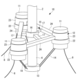
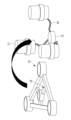
本開示の一実施形態に係る風力発電装置1は、図1に示すように、1つのタワー部2と、タワー部2に設置された風車部3と、タワー部2を洋上で支持する支持構造10などを備える。風力発電装置1は、発生した電力を電力系統へ送電するために系統連系されている。風力発電装置1は、浮体式であり、水面又は水中に浮かばされた支持構造10によって洋上に設置される。支持構造10は、アンカーケーブル8によって海底と係留される。アンカーケーブル8は、一端が海底に固定され、他端が支持構造10に接続されている。
Below, a wind
As shown in FIG. 1, a wind
タワー部2は、一方向に長い構造を有し、軸方向が設置面に対して垂直方向となるようにタワー部2の基礎部4が支持構造10に設けられる。タワー部2は、例えば1本の円柱状部材でもよいし、複数の長尺状部材が組み合わされて構成されてもよい。
The
タワー部2は、上端側において風車部3を支持する。タワー部2は、圧縮力及び曲げを主に負担する長尺状部材などから構成される。
The
タワー部2に設置された風車部3は、ナセル5と、ナセル5に収容されるロータ及び発電機と、ロータの先端に設置されたロータヘッド6と、ロータヘッド6に設けられた複数枚(例えば3枚)の翼7などを有する。
The
ナセル5は、タワー部2の上部に設置され、内部にロータや、増速機、発電機などを備える。ナセル5の一端側には、ロータヘッド6が設けられる。ロータは、ほぼ水平な軸線周りに回転可能である。ロータの一端側は、ロータヘッド6に接続され、ロータの他端側は、例えば直接的に発電機に接続され、又は、増速機若しくは油圧ポンプ・油圧モータを介して発電機に接続される。発電機は、ロータが軸周りに回転することによって生じる回転力によって駆動し発電する。
The nacelle 5 is installed at the top of the
翼7は、ロータヘッド6において、放射状に複数枚取り付けられる。複数枚の翼7は、風を受けることによって、ロータを中心にして回転する。翼7は、ピッチ制御用の旋回輪軸受を介してロータヘッド6に接続され、翼長方向に延在する翼軸周りに回動可能である。これにより、翼7のピッチ角が調整される。
A plurality of blades 7 are radially attached to the
ナセル5は、タワー部2に対して略水平面上で旋回して、ロータヘッド6の方向を風向きに合わせ、翼7の回転面を風向きに正対させる。ナセル5が略水平面上で旋回することをヨー(yaw)旋回という。ナセル5は、ナセル5とタワー部2に接続されたヨー旋回輪軸受を介して旋回する。
The nacelle 5 rotates on a substantially horizontal plane with respect to the
本実施形態によれば、風車部3は、ロータと、ロータに設けられた翼7と、ロータの回転力によって発電する発電機をそれぞれ有し、風車部3は、タワー部2によって支持される。風車部3は、風を受けて回転し発電する。
According to this embodiment, the
次に、本実施形態に係る風力発電装置1の支持構造10について説明する。
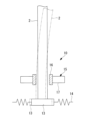
支持構造10は、図2に示すように、複数の浮体部(ポンツーン)11と、接続部材12と、支持台13と、ワイヤ部材14と、支持部材15などを備える。
Next, the
As shown in FIG. 2, the
複数の浮体部11は、それぞれ水面又は水中に浮くことが可能な構成を有しており、タワー部2の径方向外側において、タワー部2を囲むように周方向に設置される。浮体部11は、バランス良くタワー部2を支持できればよく、三つ設置されてもよいし、三つ以上設置されてもよい。図3及び図4には、浮体部11が三つ設置される場合を示し、図5及び図6には、浮体部11が四つ設置される場合を示す。
The plurality of floating
接続部材12は、例えば、第2開口部23Aが形成された第2環状部材23と、第2環状部材23の外周面に設置された長尺状部材24を有する。第2環状部材23は、浮体部11に設置される。長尺状部材24は、一端が複数の浮体部11のうち一の浮体部11と接続され、他端が複数の浮体部11のうち他の浮体部11と接続されている。長尺状部材24は、浮体部間に作用する力(曲げ、圧縮、引張など)を主に負担する。
The
支持台13は、複数の浮体部11の中間に設けられ、風力発電装置1のタワー部2の下端に設けられた基礎部4を支持する。支持台13は、浮体部11の下端よりも下方においてタワー部2の下端を支持する。すなわち、タワー部2が支持部材15を貫通して、タワー部2の下部が支持部材15よりも下方に延設されており、タワー部2の重心位置が下方に下がる。これにより、浮体部11自体の高さを小さくしても揺動に対する安定性を確保できる。したがって、浮体部11の製造にかかる時間やコストを低減できる。
The support stand 13 is provided between the plurality of floating
ワイヤ部材14は、線状部材であり、一端が浮体部11に接続され、他端が支持台13に接続される。なお、ワイヤ部材14は、一端側において、浮体部11ではなく、接続部材12、例えば接続部材12の第2環状部材23又は長尺状部材24と接続されてもよい。ワイヤ部材14は、引張力を主に負担する。ワイヤ部材14は、より線構造を有するものが適用されてもよい。これにより、ワイヤ部材14の伸縮による変形で、タワー部2と浮体部11には減衰が負荷される。その結果、タワー部2と浮体部11に生じる揺動を抑制する効果が発揮される。
The
ワイヤ部材14は、浮体部11又は接続部材12と支持台13の間で、図2に示すように、例えば、2本ずつ設置される。なお、各位置において設置されるワイヤ部材14の本数は、この例に限定されず、1本ずつでもよいし、3本以上ずつでもよい。また、フェールセーフのため、ワイヤ部材14に沿って予備のワイヤ部材(図示せず。)が併設されてもよい。
For example, two
支持部材15は、図3~図6に示すように、一端が接続部材12の第2環状部材23又は長尺状部材24に設けられ、図8に示すように、支持台13に支持されたタワー部2をタワー部2の軸方向に移動可能に側方から支持する。
As shown in FIGS. 3 to 6, the
図7に示すように、支持部材15は、例えば、第1開口部16Aが形成された第1環状部材16と、第1環状部材16の外周面に設置された長尺状部材17を有する。第1開口部16Aの内径は、タワー部2の外径よりもわずかに大きい。第1環状部材16は、第1開口部16Aにてタワー部2を挿通可能であり、第1開口部16Aの内部においてタワー部2が軸方向に移動する。図8に示すように、タワー部2は、支持部材15と接合されず、隙間を開けた状態で貫通している。タワー部2は第1環状部材16によって支持されることから、周方向の全てにわたってタワー部2の倒れが均等に防止される。
As shown in FIG. 7, the
一端が支持部材15の第1環状部材16と接続される長尺状部材17は、図3及び図5に示すように、他端が接続部材12の中間部と接続されてもよいし、図4及び図6に示すように、他端が接続部材12の端部、すなわち、浮体部11近傍に接続されてもよい。なお、支持部材15は、上述した例に限定されず、剛性や強度要求を満足できれば、他の構造を有してもよい。
The
浮体部11と接続部材12は、互いに連結されて剛接合されている。タワー部2は、従来の浮体式の支持構造と異なり、浮体部11とは剛結されない。従来の浮体式の支持構造では、タワー部と浮体部が剛結されているため、片持ち梁形式の構造体となっている。そのため、支持構造に生じる曲げモーメントが大きくなるため、タワー部と浮体部とを接合する接合部に要求される強度が大きくなる。これに対し、図8に示すように、本実施形態では、タワー部2と浮体部11は互いに剛結されず、支持部材15の第1環状部材16を通してタワー部2が貫通設置されている。また、タワー部2は、支持部材15によって軸方向に移動可能に側方から支持される。
The floating
タワー部2の鉛直自重は、支持台13からワイヤ部材14を介して浮体部11側に伝達される。浮体部とタワー部が剛結されている場合と異なり、剛結された接合部が不要となり、かつ、接合部分の構造を簡素化できる。よって、製造工程も簡略化でき、製造にかかる時間やコストを低減できる。
The vertical dead weight of the
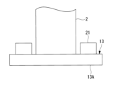
また、図9及び図10に示すように、タワー部2と支持台13の接合部分は、剛結合とされず、支持台13上においてタワー部2が水平方向に移動可能に構成されてもよい。タワー部2と支持台13の接合部分は、剛結合とされないため、接合部分を簡素化することができ、接合部分の製造にかかる時間やコストを低減できる。
Further, as shown in FIGS. 9 and 10, the joint portion between the
この場合、支持台13は、タワー部2の下端を囲むように設けられた第1突出部21を有してもよい。第1突出部21は、タワー部2と支持台13の接合部分において、タワー部2が水平方向に移動した場合の水平方向の移動を拘束する。第1突出部21は、図9に示すように、支持台13の平坦な板状部材13Aに対して上向きに突出するように設けられてもよいし、図10に示すように、支持台13自体に凹部13Bを形成することによって、タワー部2の下端を囲む第1突出部21が設けられてもよい。なお、第1突出部21によってタワー部2の水平方向の移動を拘束できれば、第1突出部21の構成は上述した例に限定されない。
In this case, the support stand 13 may include a
第1突出部21において、タワー部2と対向する面には、緩衝体(図示せず。)が設置されてもよい。これにより、タワー部2が水平方向に移動した場合に、タワー部2が直接支持台13に衝撃的に接触するのを防止でき、支持台13の損傷を軽減できる。緩衝体は、例えば、ゴムなどの高分子系材料、ハニカム構造等を有する金属系材料などである。
A buffer (not shown) may be installed on the surface of the first protruding
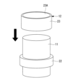
浮体部11と接続部材12は、図11及び図12に示すように、接続部材12の第2環状部材23が浮体部11の上部より挿入され、浮体部11に設けられた第2突出部22によって鉛直方向に支持される構成を有してもよい。この場合、浮体部11には、浮体部11の外周面に径方向に突出した第2突出部22が設けられる。また、接続部材12は、内部にて浮体部11を挿通可能な第2開口部23Aが形成された第2環状部材23を有する。第2環状部材23の下端は、第2突出部22と接触するように、接続部材12が浮体部11に設置される。第2環状部材23の下端が第2突出部22と接触するように、接続部材12が浮体部11に設置されることによって、接続部材12と浮体部11が連結される。
As shown in FIGS. 11 and 12, the floating
浮体部11と接続部材12が別体として製造され、接続部材12が浮体部11に嵌め込まれる方法で組み立てられることから、従来の浮体式の支持構造と異なり、現場での溶接作業などが不要となる。その結果、製造にかかる時間やコストを低減できる。
Since the floating
浮体部11は、コンクリート製、鋼製、又は、FRP製などの材料で製作され、材料は限定されない。また、浮体部11に形成される第2突出部22の材料も限定されず、浮体部11の本体の材料と異なる材料で製造されてもよい。第2突出部22は、上端が浮体部11の高さの1/2以下の位置となるように設けられるとよい。これにより、接続部材12の下端が第2突出部22の上端と接触する位置が、浮体部11の高さの1/2以下の位置となることから、構造的に安定しやすくなる。
The floating
浮体部11は、中空構造を有する。この場合、浮体部11の底板は、側壁と一体構造とされる。浮体部11の内部には、喫水高さ調整用のバラストが収容される。そのため、浮体部11の上蓋は側壁と別体構造とされる。上蓋の材料も限定されず、上蓋は、コンクリート製、鋼製、又は、FRP製などの材料で製作される。
The floating
浮体部11をコンクリート製とする場合、鋼製の浮体部11と比べて耐腐食性が向上し、メンテナンスが容易になる。また、コンクリート製の場合、軽量化することができ、型枠を用いた量産を行うことができるため、コストダウンを図ることができる。コンクリート構造を有する浮体部11は、図13に示すように、現場で打設される鉄筋コンクリート(RC)構造や、プレストレストコンクリート構造のプレテンション方式でもよい。また、コンクリート構造を有する浮体部11は、図14に示すように、複数の分割部材11aを組み合わせたものや、鋼材11bに引張力を付与するプレキャストコンクリート構造におけるポストテンション方式でもよい。さらに、鋼繊維を混合した高強度コンクリートが用いられてもよい。
When the floating
浮体部11をコンクリート製とする場合、図15に示すように、中空部分の内壁には薄板鋼板25を設置することが望ましい。これにより、浮体部11における水密性を確保できる。薄板鋼板25は、強度部材でなくてもよい。
When the floating
接続部材12と支持部材15は、図7に示すように、一体化される。また、接続部材12において第2環状部材23と長尺状部材24が一体化され、支持部材15において第1環状部材16と長尺状部材17が一体化される。製造工程において、各部材がすべて陸上において接合されて一体化されていると、現場(洋上)での組み立て工程が少なくなり、製造にかかる時間やコストを低減できる。
The connecting
接続部材12と支持部材15は、図16に示すように、複数の分割線26で接合されて一体化されてもよい。このように、接続部材12と支持部材15が一体化されない場合でも、ある程度の範囲を一体的に製造しておき、現場での接合箇所を極力低減できれば、製造にかかる時間やコストを低減できる。なお、各部材の接合を行う場合、接合方法は溶接、ボルト接合など、その方法は限定されない。溶接の場合、部材内部への浸水を抑制できる。
The connecting
図17に示すように、接続部材12の長尺状部材24は、型鋼(図17(a)及び(b),図18(a)参照)、トラス構造(図18(b)参照)、又は、ラーメン構造(図17(c),図18(c)参照)を有する。型鋼の場合、断面形状が角型でもよいし(図17(a)参照)、丸型でもよい(図17(b)参照)。長尺状部材24は、所定の強度や剛性を確保できれば、どの構造が採用されてもよい。
As shown in FIG. 17, the
図19には、本実施形態に係る支持構造10の浮体部11と接続部材12の間の接続部分の第1実施例を示す。図19に示すように、浮体部11と接続部材12は、例えば、浮体部11と接続部材12の第2環状部材23の間に充填された充填材31によって互いに固定される。充填剤は、例えばグラウト、モルタル又は接着剤などである。この場合、充填剤は、接続部材12が浮体部11に嵌め込まれて設置された後に充填される。
FIG. 19 shows a first example of a connection portion between the floating
上記構造において、図19に示すように、浮体部11の外周面側及び/又は接続部材12の第2環状部材23の内周面側にせん断荷重伝達部材32が設置されることが望ましい。せん断荷重伝達部材32は、スタッドボルト、リブ、又は、凸状に加工された表面などである。せん断荷重伝達部材32が設置されることによって、充填材31のみを充填する場合と比べて、浮体部11と接続部材12間に生じるせん断強度や引張強度、接合強度を向上させることができる。
In the above structure, as shown in FIG. 19, it is desirable that the shear
また、図20及び図21には、本実施形態に係る支持構造10の浮体部11と接続部材12の間の接続部分の第2実施例を示す。図20及び図21に示すように、浮体部11と接続部材12は、浮体部11と接続部材12との間に粘性体33が充填されてもよい。粘性体33によって浮体部11と接続部材12の間に生じる相対変位が減衰される。浮体部11の外周面側及び接続部材12の第2環状部材23の内周面側に突起部34が設置される。突起部34は、スタッドボルト、リブ、又は、凸状に加工された表面などである。粘性体33は、例えばシリコン系の材料などである。これにより、風力発電装置1の揺動時、浮体部11と接続部材12の間には相対変位が発生する。粘性体33と突起部34の間に生じる相対変位によって、浮体部11と接続部材12には粘性抵抗減衰が負荷されることになるため、浮体部11と接続部材12に生じる揺動を抑制する効果が発揮される。
Further, FIGS. 20 and 21 show a second example of the connection portion between the floating
さらに、支持部材15とタワー部2は、支持部材15とタワー部2の間に充填された粘性体(図示せず。)によって支持部材15とタワー部2の間に生じる相対変位が減衰されるようにしてもよい。この場合、タワー部2の外周面側及び支持部材15の第1環状部材16の内周面側に突起部が設置され、風力発電装置1の揺動時、粘性体と突起部の間に生じる相対変位によって、支持部材15とタワー部2には粘性抵抗減衰が負荷される。その結果、支持部材15とタワー部2に生じる揺動を抑制する効果が発揮される。
Further, relative displacement between the
本実施形態に係る風力発電装置1の製造方法について説明する。
まず、図22(a)に示すように、浮体部11が個別に製作されるとともに、製作された複数の浮体部11が乾式ドッグに設置される。そして、図22(b)及び図26に示すように、支持台13が浮体部11の中間など所定の位置に設置される。また、支持台13と浮体部11間を結合するワイヤ部材14が設置される。
A method for manufacturing the
First, as shown in FIG. 22(a), floating
他方、図26に示すように、接続部材12と支持部材15が一体化されて、又は、部品数よりも少ない数で複数の分割部材として別体化されて製作される。そして、図23(c)及び図26に示すように、乾式ドッグに設置された浮体部11の上部から落とし込む形式で接続部材12及び支持部材15と浮体部11が組み立てられる。これにより、図23(d)及び図27に示すように、浮体部11と接続部材12が結合される。
On the other hand, as shown in FIG. 26, the connecting
なお、上述した順番に限られず、例えば、支持台13が浮体部11の中間など所定の位置に設置された後、図22(b)に示した例と異なり、ワイヤ部材14を接続する前に、一体化された接続部材12及び支持部材15を浮体部11の上部から落とし込んで、接続部材12及び支持部材15と浮体部11を組み立ててもよい。その後、接続部材12と支持台13との間にワイヤ部材14が設置される。
Note that the order is not limited to the above-mentioned order, and for example, after the
次に、図24(e)及び図28に示すように、タワー部2の下部を支持台13上に設置することによって、風力発電装置1が完成する。このとき、タワー部2の上部には風車部3が設置される。その後、図24(f)及び図29に示すように、乾式ドッグ内に注水が行われ、風力発電装置1が支持構造10によって支持された状態で水面又は水中に浮いた状態となる。そして、洋上の所定の設置場所まで風力発電装置1が搬送され、図25(g)に示すように、アンカーケーブル8によって海底と係留される。
Next, as shown in FIGS. 24(e) and 28, the lower part of the
上述した製造方法によれば、特許文献1などで開示された複数の部品を個別に製作し、その後各部品を組み立てていく工法と異なり、施工工数を低減でき、施工に係る時間やコストを低減できる。また、陸上での組み立て作業となるため、洋上で作業を行うためのパージが不要となり、また、波浪などの外乱に対する影響がないため作業効率が向上する。
According to the above-mentioned manufacturing method, unlike the construction method disclosed in
以上説明した実施形態に記載の風力発電装置の支持構造及び風力発電装置は例えば以下のように把握される。
本開示に係る風力発電装置(1)の支持構造(10)は、水面又は水中に浮遊可能な複数の浮体部(11)と、一端が前記複数の浮体部のうち一の浮体部と接続され、他端が前記複数の浮体部のうち他の浮体部と接続された接続部材(12)と、前記複数の浮体部の中間に設けられ、風力発電装置のタワー部の下端を支持する支持台(13)と、一端が前記浮体部又は前記接続部材に接続され、他端が前記支持台に接続された線状のワイヤ部材(14)と、前記浮体部又は前記接続部材に設けられ、前記支持台に支持された前記タワー部を前記タワー部の軸方向に移動可能に側方から支持する支持部材(15)とを備える。
The support structure of the wind power generation device and the wind power generation device described in the embodiments described above can be understood, for example, as follows.
A support structure (10) of a wind power generation device (1) according to the present disclosure includes a plurality of floating body parts (11) that can float on a water surface or in water, and one end of which is connected to one of the plurality of floating body parts. , a connecting member (12) whose other end is connected to another of the plurality of floating body parts, and a support base that is provided between the plurality of floating body parts and supports the lower end of the tower part of the wind power generator. (13); a linear wire member (14) connected to the floating body part or the connecting member at one end and connected to the support base at the other end; The present invention includes a support member (15) that laterally supports the tower part supported by the support base so as to be movable in the axial direction of the tower part.
この構成によれば、複数の浮体部が水面又は水中に浮遊可能であり、各浮体部は、接続部材を介して接続される。複数の浮体部の中間に設けられた支持台は、ワイヤ部材を介して浮体部又は接続部材に接続され、風力発電装置のタワー部の下端を支持する。浮体部又は接続部材に設けられた支持部材は、支持台に支持されたタワー部を、タワー部の軸方向に移動可能に側方から支持する。タワー部は、浮体部と剛結されず、支持部材によって軸方向に移動可能に側方から支持される。タワー部の鉛直自重は、支持台からワイヤ部材を介して浮体部側に伝達される。浮体部とタワー部が剛結されている場合と異なり、剛結された接合部が不要となり、かつ、接合部分の構造を簡素化できる。 According to this configuration, a plurality of floating body parts can float on the water surface or in water, and each floating body part is connected via a connecting member. A support stand provided between the plurality of floating body parts is connected to the floating body parts or the connection member via a wire member, and supports the lower end of the tower part of the wind power generator. The support member provided on the floating body section or the connection member laterally supports the tower section supported by the support base so as to be movable in the axial direction of the tower section. The tower part is not rigidly connected to the floating body part, but is laterally supported by a support member so as to be movable in the axial direction. The vertical weight of the tower section is transmitted from the support base to the floating body section via the wire member. Unlike the case where the floating body part and the tower part are rigidly connected, a rigidly connected joint part is not required, and the structure of the joint part can be simplified.
本開示に係る風力発電装置の支持構造において、前記支持台は、前記浮体部の下端よりも下方において前記タワー部の下端を支持してもよい。 In the support structure for the wind power generation device according to the present disclosure, the support stand may support the lower end of the tower portion below the lower end of the floating body portion.
この構成によれば、支持台によって、浮体部の下端よりも下方においてタワー部の下端が支持され、重心位置が下方に下がることから、浮体部自体の高さを小さくしても揺動に対する安定性を確保できる。 According to this configuration, the lower end of the tower is supported by the support base below the lower end of the floating body, and the center of gravity is lowered downward, so even if the height of the floating body itself is reduced, it is stable against rocking. can ensure sex.
本開示に係る風力発電装置の支持構造において、前記支持部材は、内部にて前記タワー部を挿通可能な第1開口部(16A)が形成された第1環状部材(16)を有し、前記第1開口部内部において前記タワー部が前記軸方向に移動可能でもよい。 In the support structure for a wind power generation device according to the present disclosure, the support member includes a first annular member (16) in which a first opening (16A) through which the tower portion can be inserted, and The tower portion may be movable in the axial direction inside the first opening.
この構成によれば、支持部材は、第1開口部が形成された第1環状部材を有し、第1環状部材は、内部にてタワー部を挿通可能であり、第1開口部内部においてタワー部が軸方向に移動する。タワー部は第1環状部材によって支持されることから、周方向の全てにわたってタワー部の倒れが均等に防止される。 According to this configuration, the support member includes a first annular member in which the first opening is formed, the first annular member can pass the tower portion inside the first annular member, and the tower portion is inserted into the first opening. part moves in the axial direction. Since the tower portion is supported by the first annular member, the tower portion is evenly prevented from falling over in the entire circumferential direction.
本開示に係る風力発電装置の支持構造において、前記支持台は、前記タワー部の下端を囲むように設けられた第1突出部(21)を有してもよい。 In the support structure for a wind power generation device according to the present disclosure, the support stand may include a first protrusion (21) provided so as to surround a lower end of the tower section.
この構成によれば、支持台においてタワー部の下端を囲むように第1突出部が設けられ、第1突出部によってタワー部の水平方向の移動を拘束できる。 According to this configuration, the first protrusion is provided in the support base so as to surround the lower end of the tower, and the first protrusion can restrain horizontal movement of the tower.
本開示に係る風力発電装置の支持構造において、前記浮体部の外周面に径方向に突出した第2突出部(22)が設けられ、前記接続部材は、内部にて前記浮体部を挿通可能な第2開口部(23A)が形成された第2環状部材(22)を有し、前記第2環状部材の下端が前記第2突出部と接触するように、前記接続部材が前記浮体部に設置されてもよい。 In the support structure for a wind power generation device according to the present disclosure, a second protrusion (22) that protrudes in the radial direction is provided on the outer circumferential surface of the floating body part, and the connecting member can be inserted through the floating body part inside. The connecting member has a second annular member (22) in which a second opening (23A) is formed, and the connecting member is installed in the floating body part such that the lower end of the second annular member contacts the second protrusion. may be done.
この構成によれば、浮体部の外周面に径方向に突出した第2突出部が設けられ、接続部材は、第2開口部が形成された第2環状部材を有し、第2環状部材は、内部にて浮体部を挿通可能である。第2環状部材の下端が第2突出部と接触するように、接続部材が浮体部に設置されることによって、接続部材と浮体部が連結される。 According to this configuration, the second protrusion protruding in the radial direction is provided on the outer peripheral surface of the floating body part, the connecting member has the second annular member in which the second opening is formed, and the second annular member , it is possible to insert the floating body part inside. The connecting member and the floating body are connected by installing the connecting member on the floating body so that the lower end of the second annular member contacts the second protrusion.
本開示に係る風力発電装置の支持構造において、前記接続部材には、隣り合う前記浮体部の間において型鋼を有する部材、トラス構造を有する部材、又は、ラーメン構造を有する部材が設けられてもよい。 In the support structure for a wind power generation device according to the present disclosure, the connection member may be provided with a member having a shaped steel, a member having a truss structure, or a member having a rigid frame structure between the adjacent floating body parts. .
この構成によれば、接続部材には、型鋼を有する部材、トラス構造を有する部材、又は、ラーメン構造を有する部材が設けられることによって、隣り合う浮体部同士が接続部材を介して接続される。 According to this configuration, the connecting member is provided with a member having a shaped steel, a member having a truss structure, or a member having a rigid frame structure, so that adjacent floating body parts are connected to each other via the connecting member.
本開示に係る風力発電装置の支持構造において、前記接続部材と前記支持部材は一体化された構成を有してもよい。 In the support structure for a wind power generator according to the present disclosure, the connection member and the support member may have an integrated configuration.
この構成によれば、接続部材と支持部材が一体化された構成を有することから、洋上での組み立て工程における工数を低減できる。 According to this configuration, since the connecting member and the supporting member are integrated, the number of man-hours in the assembly process at sea can be reduced.
本開示に係る風力発電装置の支持構造において、前記浮体部と前記接続部材は、前記浮体部と前記接続部材の間に充填された充填材(31)によって互いに固定されてもよい。 In the support structure for a wind power generator according to the present disclosure, the floating body part and the connection member may be fixed to each other by a filler (31) filled between the floating body part and the connection member.
この構成によれば、浮体部と接続部材の間に充填材が充填されることによって浮体部と接続部材は互いに固定される。充填剤は、例えばグラウト、モルタル又は接着剤などである。 According to this configuration, the floating body part and the connecting member are fixed to each other by filling the space between the floating body part and the connecting member. Fillers are, for example, grouts, mortar or adhesives.
本開示に係る風力発電装置の支持構造において、前記浮体部と前記接続部材は、前記浮体部と前記接続部材の間に充填された粘性体によって前記浮体部と前記接続部材の間に生じる相対変位が減衰されてもよい。 In the support structure for a wind power generation device according to the present disclosure, the floating body portion and the connection member are arranged such that a relative displacement occurs between the floating body portion and the connection member due to a viscous material filled between the floating body portion and the connection member. may be attenuated.
この構成によれば、浮体部と接続部材の間に粘性体(33)が充填され、粘性体によって浮体部と接続部材の間に生じる相対変位が減衰される。 According to this configuration, the viscous body (33) is filled between the floating body part and the connecting member, and the relative displacement occurring between the floating body part and the connecting member is attenuated by the viscous body.
本開示に係る風力発電装置の支持構造において、前記支持部材と前記タワー部は、前記支持部材と前記タワー部の間に充填された粘性体によって前記支持部材と前記タワー部の間に生じる相対変位が減衰されてもよい。 In the support structure of the wind power generation device according to the present disclosure, the support member and the tower section are arranged such that a relative displacement occurs between the support member and the tower section due to a viscous material filled between the support member and the tower section. may be attenuated.
この構成によれば、支持部材とタワー部の間に粘性体が充填され、粘性体によって支持部材とタワー部の間に生じる相対変位が減衰される。 According to this configuration, the viscous material is filled between the support member and the tower section, and the relative displacement occurring between the support member and the tower section is attenuated by the viscous material.
本開示に係る風力発電装置は、上述した風力発電装置の支持構造を備える。 A wind power generation device according to the present disclosure includes the support structure for the wind power generation device described above.
1 :風力発電装置
2 :タワー部
3 :風車部
4 :基礎部
5 :ナセル
6 :ロータヘッド
7 :翼
8 :アンカーケーブル
10 :支持構造
11 :浮体部
11a :分割部材
11b :鋼材
12 :接続部材
13 :支持台
13A :板状部材
13B :凹部
14 :ワイヤ部材
15 :支持部材
16 :第1環状部材
16A :第1開口部
17 :長尺状部材
21 :第1突出部
22 :第2突出部
23 :第2環状部材
23A :第2開口部
24 :長尺状部材
25 :薄板鋼板
26 :分割線
31 :充填材
32 :せん断荷重伝達部材
33 :粘性体
34 :突起部
1 : Wind power generator 2 : Tower part 3 : Wind turbine part 4 : Foundation part 5 : Nacelle 6 : Rotor head 7 : Wings 8 : Anchor cable 10 : Support structure 11 : Floating
Claims (10)
一端が前記複数の浮体部のうち一の浮体部と接続され、他端が前記複数の浮体部のうち他の浮体部と接続された接続部材と、
前記複数の浮体部の中間に設けられ、風力発電装置のタワー部の下端を支持する支持台と、
一端が前記浮体部又は前記接続部材に接続され、他端が前記支持台に接続された線状のワイヤ部材と、
前記浮体部又は前記接続部材に設けられ、前記支持台に支持された前記タワー部を前記タワー部の軸方向に移動可能に側方から支持する支持部材と、
を備え、
前記浮体部の外周面に径方向に突出した第2突出部が設けられ、
前記接続部材は、内部にて前記浮体部を挿通可能な第2開口部が形成された第2環状部材を有し、
前記第2環状部材の下端が前記第2突出部と接触するように、前記接続部材が前記浮体部に設置される風力発電装置の支持構造。 A plurality of floating body parts that can float on the water surface or in the water;
a connecting member having one end connected to one of the plurality of floating body parts and the other end connected to another floating body part among the plurality of floating body parts;
a support stand provided between the plurality of floating body parts and supporting the lower end of the tower part of the wind power generator;
a linear wire member having one end connected to the floating body part or the connection member and the other end connected to the support base;
a support member that is provided on the floating body section or the connection member and supports the tower section supported by the support base from the side so as to be movable in the axial direction of the tower section;
Equipped with
A second protrusion protruding in the radial direction is provided on the outer peripheral surface of the floating body part,
The connecting member has a second annular member in which a second opening through which the floating body portion can be inserted is formed;
A support structure for a wind power generator , wherein the connecting member is installed on the floating body part such that a lower end of the second annular member contacts the second protruding part .
一端が前記複数の浮体部のうち一の浮体部と接続され、他端が前記複数の浮体部のうち他の浮体部と接続された接続部材と、
前記複数の浮体部の中間に設けられ、風力発電装置のタワー部の下端を支持する支持台と、
一端が前記浮体部又は前記接続部材に接続され、他端が前記支持台に接続された線状のワイヤ部材と、
前記浮体部又は前記接続部材に設けられ、前記支持台に支持された前記タワー部を前記タワー部の軸方向に移動可能に側方から支持する支持部材と、
を備え、
前記浮体部と前記接続部材は、前記浮体部と前記接続部材の間に充填された充填材によって互いに固定される風力発電装置の支持構造。 A plurality of floating body parts that can float on the water surface or in the water;
a connecting member having one end connected to one of the plurality of floating body parts and the other end connected to another floating body part among the plurality of floating body parts;
a support stand provided between the plurality of floating body parts and supporting the lower end of the tower part of the wind power generator;
a linear wire member having one end connected to the floating body part or the connection member and the other end connected to the support base;
a support member that is provided on the floating body section or the connection member and supports the tower section supported by the support base from the side so as to be movable in the axial direction of the tower section;
Equipped with
The floating body part and the connection member are fixed to each other by a filler filled between the floating body part and the connection member .
一端が前記複数の浮体部のうち一の浮体部と接続され、他端が前記複数の浮体部のうち他の浮体部と接続された接続部材と、
前記複数の浮体部の中間に設けられ、風力発電装置のタワー部の下端を支持する支持台と、
一端が前記浮体部又は前記接続部材に接続され、他端が前記支持台に接続された線状のワイヤ部材と、
前記浮体部又は前記接続部材に設けられ、前記支持台に支持された前記タワー部を前記タワー部の軸方向に移動可能に側方から支持する支持部材と、
を備え、
前記浮体部と前記接続部材は、前記浮体部と前記接続部材の間に充填された粘性体によって前記浮体部と前記接続部材の間に生じる相対変位が減衰される風力発電装置の支持構造。 A plurality of floating body parts that can float on the water surface or in the water;
a connecting member having one end connected to one of the plurality of floating body parts and the other end connected to another floating body part among the plurality of floating body parts;
a support stand provided between the plurality of floating body parts and supporting the lower end of the tower part of the wind power generator;
a linear wire member having one end connected to the floating body part or the connection member and the other end connected to the support base;
a support member that is provided on the floating body section or the connection member and supports the tower section supported by the support base from the side so as to be movable in the axial direction of the tower section;
Equipped with
The floating body part and the connection member are provided in a support structure for a wind power generator, in which relative displacement occurring between the floating body part and the connection member is attenuated by a viscous material filled between the floating body part and the connection member .
一端が前記複数の浮体部のうち一の浮体部と接続され、他端が前記複数の浮体部のうち他の浮体部と接続された接続部材と、
前記複数の浮体部の中間に設けられ、風力発電装置のタワー部の下端を支持する支持台と、
一端が前記浮体部又は前記接続部材に接続され、他端が前記支持台に接続された線状のワイヤ部材と、
前記浮体部又は前記接続部材に設けられ、前記支持台に支持された前記タワー部を前記タワー部の軸方向に移動可能に側方から支持する支持部材と、
を備え、
前記支持部材と前記タワー部は、前記支持部材と前記タワー部の間に充填された粘性体によって前記支持部材と前記タワー部の間に生じる相対変位が減衰される風力発電装置の支持構造。 A plurality of floating body parts that can float on the water surface or in the water;
a connecting member having one end connected to one of the plurality of floating body parts and the other end connected to another floating body part among the plurality of floating body parts;
a support stand provided between the plurality of floating body parts and supporting the lower end of the tower part of the wind power generator;
a linear wire member having one end connected to the floating body part or the connection member and the other end connected to the support base;
a support member that is provided on the floating body section or the connection member and supports the tower section supported by the support base from the side so as to be movable in the axial direction of the tower section;
Equipped with
The support structure for a wind power generator is such that the support member and the tower part are configured such that a relative displacement occurring between the support member and the tower part is attenuated by a viscous material filled between the support member and the tower part.
Priority Applications (5)
| Application Number | Priority Date | Filing Date | Title |
|---|---|---|---|
| JP2019213415A JP7433859B2 (en) | 2019-11-26 | 2019-11-26 | Support structure for wind power generation equipment and wind power generation equipment |
| PCT/JP2020/042002 WO2021106560A1 (en) | 2019-11-26 | 2020-11-11 | Support structure for wind power generation device and wind power generation device |
| US17/774,236 US12085057B2 (en) | 2019-11-26 | 2020-11-11 | Support structure for wind power generation device and wind power generation device |
| EP20894347.2A EP4039969A4 (en) | 2019-11-26 | 2020-11-11 | SUPPORT STRUCTURE FOR A WIND POWER GENERATING DEVICE AND WIND POWER GENERATING DEVICE |
| TW109140086A TWI755159B (en) | 2019-11-26 | 2020-11-17 | Support structure of wind power generator and wind power generator |
Applications Claiming Priority (1)
| Application Number | Priority Date | Filing Date | Title |
|---|---|---|---|
| JP2019213415A JP7433859B2 (en) | 2019-11-26 | 2019-11-26 | Support structure for wind power generation equipment and wind power generation equipment |
Publications (2)
| Publication Number | Publication Date |
|---|---|
| JP2021085341A JP2021085341A (en) | 2021-06-03 |
| JP7433859B2 true JP7433859B2 (en) | 2024-02-20 |
Family
ID=76088669
Family Applications (1)
| Application Number | Title | Priority Date | Filing Date |
|---|---|---|---|
| JP2019213415A Active JP7433859B2 (en) | 2019-11-26 | 2019-11-26 | Support structure for wind power generation equipment and wind power generation equipment |
Country Status (5)
| Country | Link |
|---|---|
| US (1) | US12085057B2 (en) |
| EP (1) | EP4039969A4 (en) |
| JP (1) | JP7433859B2 (en) |
| TW (1) | TWI755159B (en) |
| WO (1) | WO2021106560A1 (en) |
Families Citing this family (14)
| Publication number | Priority date | Publication date | Assignee | Title |
|---|---|---|---|---|
| WO2023004117A2 (en) * | 2021-07-22 | 2023-01-26 | Trendsetter Vulcan Offshore, Inc. | Off-shore wind turbine system and method of installation |
| KR102452240B1 (en) * | 2021-08-18 | 2022-10-11 | 에스오씨기술지주 주식회사 | Precast concrete box structure for floating offshore structure and The construction method thereof |
| JP2023116313A (en) * | 2022-02-09 | 2023-08-22 | 三菱重工業株式会社 | floating structure |
| JP2024031066A (en) * | 2022-08-25 | 2024-03-07 | 国立大学法人九州大学 | Combined wind/wave power generation device |
| JP2024032522A (en) * | 2022-08-29 | 2024-03-12 | 大成建設株式会社 | How to launch a floating foundation |
| JP2024032526A (en) * | 2022-08-29 | 2024-03-12 | 大成建設株式会社 | How to make a floating foundation |
| IT202200024477A1 (en) * | 2022-11-28 | 2024-05-28 | Fincantieri Spa | METHOD OF CONSTRUCTION AND LAUNCH OF AN OFFSHORE SEMI-SUBMERSIBLE PLATFORM AND AN OFFSHORE SEMI-SUBMERSIBLE PLATFORM CONSTRUCTED AS SUCH |
| GB2642150A (en) * | 2023-03-13 | 2025-12-31 | Hiseas Energy Inc | Floating wind power generation platform for offshore deployment |
| NO348291B1 (en) * | 2023-04-21 | 2024-11-11 | Odfjell Oceanwind As | Load out method and system for offshore floating wind turbine |
| DE102023126005A1 (en) * | 2023-09-26 | 2025-03-27 | Rwe Offshore Wind Gmbh | Production plant for producing a floating foundation for an offshore structure |
| CN117167198B (en) * | 2023-10-25 | 2024-02-06 | 泰州巨纳新能源有限公司 | Wind power generation equipment based on novel energy |
| CN117588369A (en) * | 2023-12-07 | 2024-02-23 | 中国科学院广州能源研究所 | A wind-wave integrated power generation platform and anti-overturning rapid balancing system |
| EP4570639A1 (en) * | 2023-12-11 | 2025-06-18 | TotalEnergies OneTech | An assembly for producing offshore electricity comprising a double anchored floating support |
| CN119844277B (en) * | 2025-03-12 | 2025-10-31 | 南方电网电力科技股份有限公司 | Offshore power generation platform |
Citations (7)
| Publication number | Priority date | Publication date | Assignee | Title |
|---|---|---|---|---|
| JP2005180351A (en) | 2003-12-19 | 2005-07-07 | Yoshiro Shinoda | Water surface wind power generating device |
| JP2007263077A (en) | 2006-03-29 | 2007-10-11 | National Maritime Research Institute | Offshore wind power generation facilities |
| WO2011057940A2 (en) | 2009-11-13 | 2011-05-19 | Vestas Wind Systems A/S | Floating off-shore wind turbine |
| WO2016079540A1 (en) | 2014-11-20 | 2016-05-26 | Concrete Marine Solutions Limited | A floating support structure for a wind turbine and method for installing same |
| JP2016141983A (en) | 2015-01-30 | 2016-08-08 | 清水建設株式会社 | Floating offshore structure construction method and floating offshore structure |
| JP2017516945A (en) | 2014-05-27 | 2017-06-22 | エステイコ・ソシエダッド・アノニマ・プロフェシオナルEsteyco S.A.P. | Floating substructure for wind turbine and installation method thereof |
| CN109322780A (en) | 2018-12-12 | 2019-02-12 | 国电联合动力技术有限公司 | Wind energy on the sea wave energy combined generating system |
Family Cites Families (17)
| Publication number | Priority date | Publication date | Assignee | Title |
|---|---|---|---|---|
| GB1593361A (en) | 1977-05-09 | 1981-07-15 | Borg Warner | Control system for regulating large capacity rotating machinery |
| JPS5848246Y2 (en) | 1980-09-26 | 1983-11-04 | 三千丸 熊切 | garbage container |
| JPS6336436U (en) | 1986-08-20 | 1988-03-09 | ||
| US8689721B2 (en) * | 2010-03-04 | 2014-04-08 | Jin Wang | Vertically installed spar and construction methods |
| EP2836708B1 (en) | 2012-04-13 | 2019-02-27 | University of Maine System Board of Trustees | Floating wind turbine platform and method of assembling |
| JP5758501B2 (en) | 2012-08-10 | 2015-08-05 | 三菱重工業株式会社 | Floating wind power generator |
| DK3382201T3 (en) | 2013-04-01 | 2020-04-27 | Nippon Steel Corp | Liquid body structure |
| GB201507661D0 (en) * | 2015-05-05 | 2015-06-17 | Oceanflow Dev Ltd | System for assembling a floating offshore wind turbine |
| US11208987B2 (en) * | 2016-03-15 | 2021-12-28 | Stiesdal Offshore Technologies A/S | Floating wind turbine and a method for the installation of such floating wind turbine |
| NL2017594B1 (en) * | 2016-10-10 | 2018-04-16 | Delft Offshore Turbine B V | Offshore structure comprising a coated slip joint and method for forming the same |
| CN208564867U (en) | 2018-07-11 | 2019-03-01 | 明阳智慧能源集团股份公司 | A semi-submersible offshore wind turbine base platform |
| JP7590012B2 (en) * | 2020-04-16 | 2024-11-26 | ユニバーシティー オブ メイン システム ボード オブ トラスティーズ | Method for Assembling and Deploying a Floating Offshore Wind Turbine Platform |
| SE544127C2 (en) * | 2020-04-30 | 2022-01-04 | Bassoe Tech Ab | Floating semi-submersible wind energy platform with t-shaped pontoon and its assembly |
| KR102788620B1 (en) * | 2020-06-30 | 2025-03-28 | 미츠비시 조우센 가부시키가이샤 | Floating body of offshore windmill |
| EP3933192A1 (en) * | 2020-07-02 | 2022-01-05 | Siemens Gamesa Renewable Energy A/S | Towing of a floating wind turbine |
| DE102020123375A1 (en) * | 2020-09-08 | 2022-03-10 | Rwe Renewables Gmbh | Floating offshore wind turbine |
| US20230382495A1 (en) * | 2022-05-31 | 2023-11-30 | University Of Massachusetts | Mobile floating offshore wind energy system |
-
2019
- 2019-11-26 JP JP2019213415A patent/JP7433859B2/en active Active
-
2020
- 2020-11-11 EP EP20894347.2A patent/EP4039969A4/en active Pending
- 2020-11-11 US US17/774,236 patent/US12085057B2/en active Active
- 2020-11-11 WO PCT/JP2020/042002 patent/WO2021106560A1/en not_active Ceased
- 2020-11-17 TW TW109140086A patent/TWI755159B/en active
Patent Citations (7)
| Publication number | Priority date | Publication date | Assignee | Title |
|---|---|---|---|---|
| JP2005180351A (en) | 2003-12-19 | 2005-07-07 | Yoshiro Shinoda | Water surface wind power generating device |
| JP2007263077A (en) | 2006-03-29 | 2007-10-11 | National Maritime Research Institute | Offshore wind power generation facilities |
| WO2011057940A2 (en) | 2009-11-13 | 2011-05-19 | Vestas Wind Systems A/S | Floating off-shore wind turbine |
| JP2017516945A (en) | 2014-05-27 | 2017-06-22 | エステイコ・ソシエダッド・アノニマ・プロフェシオナルEsteyco S.A.P. | Floating substructure for wind turbine and installation method thereof |
| WO2016079540A1 (en) | 2014-11-20 | 2016-05-26 | Concrete Marine Solutions Limited | A floating support structure for a wind turbine and method for installing same |
| JP2016141983A (en) | 2015-01-30 | 2016-08-08 | 清水建設株式会社 | Floating offshore structure construction method and floating offshore structure |
| CN109322780A (en) | 2018-12-12 | 2019-02-12 | 国电联合动力技术有限公司 | Wind energy on the sea wave energy combined generating system |
Also Published As
| Publication number | Publication date |
|---|---|
| US20220381226A1 (en) | 2022-12-01 |
| EP4039969A1 (en) | 2022-08-10 |
| US12085057B2 (en) | 2024-09-10 |
| WO2021106560A1 (en) | 2021-06-03 |
| JP2021085341A (en) | 2021-06-03 |
| EP4039969A4 (en) | 2022-11-16 |
| TWI755159B (en) | 2022-02-11 |
| TW202129148A (en) | 2021-08-01 |
Similar Documents
| Publication | Publication Date | Title |
|---|---|---|
| JP7433859B2 (en) | Support structure for wind power generation equipment and wind power generation equipment | |
| US8458963B2 (en) | Device for a bending moment deficient strut connection | |
| KR102155394B1 (en) | Floating offshore wind power generation facility | |
| EP2836708B1 (en) | Floating wind turbine platform and method of assembling | |
| US9394035B2 (en) | Floating wind turbine platform and method of assembling | |
| KR102552328B1 (en) | Floating wind power generation device having a plurality of power converters | |
| US8752495B2 (en) | Floating foundation for mass production | |
| US20170218919A1 (en) | Wind tracing, rotational, semi-submerged raft for wind power generation and a construction method thereof | |
| KR101318111B1 (en) | Substructure of hybrid offshore wind turbine with multi-pile for reducing wave forces, and constructing method for the same | |
| CN113653601A (en) | Semi-submersible floating type fan device and system | |
| JP2011157971A (en) | Support structure for supporting offshore wind turbine | |
| JP6901867B2 (en) | Floating offshore platform | |
| TW202244388A (en) | A buoyant structure for receiving a tower of a wind turbine in offshore deployment | |
| JP7785752B2 (en) | A reinforced concrete floating platform suitable for the offshore wind industry | |
| WO2010117289A9 (en) | Truss tower | |
| KR101164227B1 (en) | Offshore wind turbine structure using steel pipe pile foundation and prefabricated structure | |
| CN116201696B (en) | Stretch-draw integral offshore wind power generation supporting structure | |
| GB2505192A (en) | A pile sleeve connection for a monopole foundation | |
| CN212003442U (en) | A lattice prestressed concrete wind power tower | |
| JP2026503659A (en) | Semi-submersible float for offshore wind turbines and method for constructing such float | |
| KR20250129835A (en) | Sub structure for floating wind turbine and floating wind turbine with the same |
Legal Events
| Date | Code | Title | Description |
|---|---|---|---|
| A621 | Written request for application examination |
Free format text: JAPANESE INTERMEDIATE CODE: A621 Effective date: 20220914 |
|
| A131 | Notification of reasons for refusal |
Free format text: JAPANESE INTERMEDIATE CODE: A131 Effective date: 20230815 |
|
| A521 | Request for written amendment filed |
Free format text: JAPANESE INTERMEDIATE CODE: A523 Effective date: 20231016 |
|
| TRDD | Decision of grant or rejection written | ||
| A01 | Written decision to grant a patent or to grant a registration (utility model) |
Free format text: JAPANESE INTERMEDIATE CODE: A01 Effective date: 20240109 |
|
| A61 | First payment of annual fees (during grant procedure) |
Free format text: JAPANESE INTERMEDIATE CODE: A61 Effective date: 20240207 |
|
| R150 | Certificate of patent or registration of utility model |
Ref document number: 7433859 Country of ref document: JP Free format text: JAPANESE INTERMEDIATE CODE: R150 |