JP2011157971A - Support structure for supporting offshore wind turbine - Google Patents
Support structure for supporting offshore wind turbine Download PDFInfo
- Publication number
- JP2011157971A JP2011157971A JP2011021071A JP2011021071A JP2011157971A JP 2011157971 A JP2011157971 A JP 2011157971A JP 2011021071 A JP2011021071 A JP 2011021071A JP 2011021071 A JP2011021071 A JP 2011021071A JP 2011157971 A JP2011157971 A JP 2011157971A
- Authority
- JP
- Japan
- Prior art keywords
- support structure
- tower
- post
- stress
- narrow
- Prior art date
- Legal status (The legal status is an assumption and is not a legal conclusion. Google has not performed a legal analysis and makes no representation as to the accuracy of the status listed.)
- Pending
Links
Images


Classifications
-
- F—MECHANICAL ENGINEERING; LIGHTING; HEATING; WEAPONS; BLASTING
- F03—MACHINES OR ENGINES FOR LIQUIDS; WIND, SPRING, OR WEIGHT MOTORS; PRODUCING MECHANICAL POWER OR A REACTIVE PROPULSIVE THRUST, NOT OTHERWISE PROVIDED FOR
- F03D—WIND MOTORS
- F03D13/00—Assembly, mounting or commissioning of wind motors; Arrangements specially adapted for transporting wind motor components
- F03D13/10—Assembly of wind motors; Arrangements for erecting wind motors
-
- E—FIXED CONSTRUCTIONS
- E02—HYDRAULIC ENGINEERING; FOUNDATIONS; SOIL SHIFTING
- E02B—HYDRAULIC ENGINEERING
- E02B17/00—Artificial islands mounted on piles or like supports, e.g. platforms on raisable legs or offshore constructions; Construction methods therefor
- E02B17/0004—Nodal points
-
- E—FIXED CONSTRUCTIONS
- E02—HYDRAULIC ENGINEERING; FOUNDATIONS; SOIL SHIFTING
- E02B—HYDRAULIC ENGINEERING
- E02B17/00—Artificial islands mounted on piles or like supports, e.g. platforms on raisable legs or offshore constructions; Construction methods therefor
- E02B2017/0056—Platforms with supporting legs
- E02B2017/0073—Details of sea bottom engaging footing
- E02B2017/0082—Spudcans, skirts or extended feet
-
- E—FIXED CONSTRUCTIONS
- E02—HYDRAULIC ENGINEERING; FOUNDATIONS; SOIL SHIFTING
- E02B—HYDRAULIC ENGINEERING
- E02B17/00—Artificial islands mounted on piles or like supports, e.g. platforms on raisable legs or offshore constructions; Construction methods therefor
- E02B2017/0091—Offshore structures for wind turbines
-
- Y—GENERAL TAGGING OF NEW TECHNOLOGICAL DEVELOPMENTS; GENERAL TAGGING OF CROSS-SECTIONAL TECHNOLOGIES SPANNING OVER SEVERAL SECTIONS OF THE IPC; TECHNICAL SUBJECTS COVERED BY FORMER USPC CROSS-REFERENCE ART COLLECTIONS [XRACs] AND DIGESTS
- Y02—TECHNOLOGIES OR APPLICATIONS FOR MITIGATION OR ADAPTATION AGAINST CLIMATE CHANGE
- Y02E—REDUCTION OF GREENHOUSE GAS [GHG] EMISSIONS, RELATED TO ENERGY GENERATION, TRANSMISSION OR DISTRIBUTION
- Y02E10/00—Energy generation through renewable energy sources
- Y02E10/70—Wind energy
- Y02E10/72—Wind turbines with rotation axis in wind direction
Abstract
Description
本発明は、洋上風車を支持するための支持構造体に関する。本発明はさらに、風車に関する。 The present invention relates to a support structure for supporting an offshore wind turbine. The invention further relates to a windmill.
洋上風車の基礎は、通常3つのグループに分けられ、重力式基礎、モノパイル式基礎、及び最新式基礎、例えば三脚又はサクションバケット基礎がある。 Offshore wind turbine foundations are usually divided into three groups: gravity foundations, monopile foundations, and modern foundations such as tripod or suction bucket foundations.
重力式基礎は一般的にコンクリートから形成されている。重力式基礎は、中空で、場合によって浮揚エレメントを用いて支持された、設置現場への浮揚のための十分な浮力を有しているか、又ははしけによって輸送され、所定の場所に持ち上げられてよい。基礎自体の重量は、かんらん石等の重いタイプのバラストを積載することによって増大させられる。重力式基礎は、大型風車及び/又は大きな水深の場合に極めて高価となる傾向があるという欠点がある。 Gravity foundations are generally made of concrete. The gravity foundation is hollow and may have sufficient buoyancy for levitation to the installation site, optionally supported by levitation elements, or may be transported by a barge and lifted into place . The weight of the foundation itself is increased by loading heavy types of ballast such as olivine. Gravity foundations have the disadvantage that they tend to be very expensive in the case of large windmills and / or large water depths.
モノパイル式基礎は、通常4〜5mの直径を有する鋼製パイルから成る。パイルは、地下のタイプに応じて約20〜30m海底に打ち込まれる。モノパイル式基礎は、タービンタワーを水中及び海底へ有効に延長させている。 Monopile foundations usually consist of steel piles with a diameter of 4-5 m. The pile is driven into the seabed about 20-30m depending on the type of underground. The monopile foundation effectively extends the turbine tower underwater and to the sea floor.
この基礎の重要な利点は、海底の準備が不要であるということである。その一方で、高荷重くい打ち機が必要とされ、この基礎形式は、海底に多くの大きな巨れきが存在する場所には適していない。また、モノパイル式基礎は、大型風車及び/又は大きな水深の場合に高価となる傾向がある。 An important advantage of this foundation is that no seabed preparation is required. On the other hand, a heavy-duty pile driver is required, and this basic form is not suitable for locations where there are many large debris on the sea floor. Monopile foundations also tend to be expensive for large windmills and / or large water depths.
最も一般的な最新式洋上基礎は、三脚基礎である。この形式の基礎は、オイル産業における周縁洋上フィールドのための軽量かつ費用対効果の高い3脚式鋼製ジャケットに関する経験を生かす。この構造は通常、中央のパイプと、3つの傾斜した脚部とから成る。3つの脚部は、底部において結合されており、中央のパイプにも結合されている。各脚部の端部には、海底に深く打ち込まれた鋼製パイルを取り囲むジャケットとして、短い鉛直のパイプが使用されている。ジャケットの打込みが完了すると、ジャケットに高強度モルタルが噴射され、パイルと脚部との強固な結合が確立される。 The most common modern offshore foundation is a tripod foundation. This type of foundation leverages experience with a lightweight and cost-effective tripod steel jacket for the offshore field in the oil industry. This structure usually consists of a central pipe and three inclined legs. The three legs are joined at the bottom and are also joined to the central pipe. At the end of each leg, a short vertical pipe is used as a jacket surrounding a steel pile driven deep into the seabed. When the driving of the jacket is completed, high-strength mortar is sprayed onto the jacket, and a firm bond between the pile and the leg is established.
スチール三脚は、極めて要求の厳しい、複雑な、疲労負荷された溶接を備えた物理的に極めて大きな構造であるという欠点を有する。 Steel tripods have the disadvantage that they are physically very large structures with extremely demanding, complex, fatigue-loaded welds.
洋上風車のためのこれらの及びほとんどのその他の公知の基礎に共通していることは、ウインドファーム現場に設置された場合に、風車タワーを支持する基礎構造が水面から出るということである。これは、水面下での締結具(ボルト等)を含む結合部の構成が困難かつ危険であるという明白な理由によるものである。 Common to these and most other known foundations for offshore wind turbines is that the foundation structure that supports the wind turbine tower emerges from the water surface when installed at a wind farm site. This is for the obvious reason that the construction of the joints including the fasteners (bolts etc.) under the surface of the water is difficult and dangerous.
1つの例外は、欧州特許第1884598号明細書に開示された基礎である。欧州特許第1884598号明細書には、パイルと上部構造とを含む洋上基礎が開示されている。パイルは、海底に打ち込まれ、海底から限定された範囲だけしか突出していない。パイルは、パイルの上部に固定される上部構造のための基礎スタブを提供する。この場合、困難なことは、パイルと上部構造との結合を確立すること、つまり、通常は高強度モルタルを噴射することによって行われる作業、である。 One exception is the basis disclosed in EP 1844598. EP 1848598 discloses an offshore foundation including a pile and a superstructure. The pile is driven into the seabed and protrudes only to a limited extent from the seabed. The pile provides a foundation stub for the superstructure that is secured to the top of the pile. In this case, the difficulty is to establish a bond between the pile and the superstructure, ie the work usually done by injecting high strength mortar.
ほとんど全ての洋上基礎に共通することは、構造の耐荷重部分が、通常、基礎のあらゆる与えられた部分において、圧縮荷重と引張荷重とを受けるということである。なぜならば、風車に対する外部荷重は、全ての方向から来ることができるからである。さらに、運転荷重による応力は、通常、圧縮応力と引張応力との間で振動する。 Common to almost all offshore foundations is that the load-bearing part of the structure is usually subjected to compressive and tensile loads in every given part of the foundation. This is because the external load on the windmill can come from all directions. Furthermore, the stress due to the operating load usually oscillates between compressive stress and tensile stress.
この理由から鋼は好適な材料である。なぜならば、鋼は、変化する応力条件において良好に働くからである。さらに、鋼は、質量当たりの強度が、例えばコンクリートよりも著しく優れているという利点を有する。従って、タワーは、道路輸送を可能にするために、通常は鋼から形成されている。しかしながら、鋼は、コンクリートと比較して3つの主な欠点を有する。第1に、強度に関する価格が著しく大きく、経済の変動に大きく影響される。第2に、風車における鋼のために、疲労はしばしば設計推進要因であり、極端な荷重はコンクリートのためである。コンクリートタワー又は基礎は、従って、適切に扱われるならば自動的により長い寿命を有する。第3に、鋼は、海洋環境における腐食を回避するために極めて慎重な表面処理を必要とする。 For this reason, steel is a preferred material. This is because steel works well in changing stress conditions. Furthermore, steel has the advantage that its strength per mass is significantly better than eg concrete. Thus, the tower is usually made of steel to allow road transport. However, steel has three main drawbacks compared to concrete. First, strength-related prices are significantly higher and are greatly affected by economic fluctuations. Second, for steel in windmills, fatigue is often a design driver and extreme loads are for concrete. A concrete tower or foundation therefore automatically has a longer life if handled properly. Third, steel requires extremely careful surface treatment to avoid corrosion in the marine environment.
モノパイル式基礎及び風車発電機は、通常、例えば、モノパイル、移行部材、2〜3つのタワー部分、ナセル、及び翼の部品として、ジャッキアップ船に設置される。通常、基礎及び風車圧電機は2つの工程で設置されるので、ジャッキアップは、各風車発電機位置に2回設置されなければならない。風車は洋上で組み立てられるので、高価な船時間及び人員時間が使用されるので、完全な試験はさらに困難であり、洋上で行われなければならない。さらに、ジャッキアップ船は機器の最新式の部材である。ジャッキアップ船は、例えば、高価なジャッキアップシステムと、多数の可動部分を含む大型の回転クレーンとを有する。 Monopile foundations and windmill generators are typically installed on jack-up ships, for example, as monopile, transition members, 2-3 tower parts, nacelles, and wing components. Usually, the foundation and windmill piezoelectric machine are installed in two steps, so the jackup must be installed twice at each windmill generator position. Since windmills are assembled offshore, expensive ship time and personnel time are used, so complete testing is more difficult and must be done offshore. In addition, the jack-up ship is a state-of-the-art component of equipment. The jack-up ship has, for example, an expensive jack-up system and a large rotating crane including a large number of moving parts.
1つの例外は、欧州特許第1058787号明細書に開示された基礎であり、この場合、タワーは、ポストテンションケーブルを用いて圧縮した状態に保たれたモジュールから形成されている。この場合、欠点は、ポストテンションケーブルにおいて使用されるような高強度鋼は、腐食及び水素脆性を受けやすいということである。従って、水面下に据え付けられた構造体の外壁におけるチャネルに挿入されたポストテンションケーブルの長期的な一体性は、疑わしい。 One exception is the basis disclosed in EP 1058787, in which the tower is formed from a module that is kept compressed using a post-tension cable. In this case, the disadvantage is that high strength steels such as those used in post tension cables are susceptible to corrosion and hydrogen embrittlement. Therefore, the long-term integrity of post-tension cables inserted into channels in the outer wall of the structure installed below the surface of the water is questionable.
本発明の第1の課題は、洋上風車を支持するための有利な支持構造を提供することである。本発明の第2の課題は、有利な風車を提供することである。 The first object of the present invention is to provide an advantageous support structure for supporting an offshore wind turbine. The second object of the present invention is to provide an advantageous wind turbine.
第1の課題は、請求項1に記載の洋上風車を支持するための支持構造によって解決される。第2の課題は、請求項15に記載の風車によって解決される。従属請求項は、発明の別の発展形を規定している。
The first problem is solved by a support structure for supporting an offshore wind turbine according to claim 1. The second problem is solved by the wind turbine according to
洋上風車を支持するための本発明の支持構造は、海底及びタワーの少なくとも一部に少なくとも部分的に接触するように構成された基礎を有している。基礎及びタワーの少なくとも一部は1つの部分である。これは、基礎へのタワーの費用のかかる固定がもはや不要であるという利点を有する。 The support structure of the present invention for supporting an offshore wind turbine has a foundation configured to at least partially contact the seabed and at least a portion of the tower. At least part of the foundation and tower is a part. This has the advantage that expensive fixing of the tower to the foundation is no longer necessary.
本発明に関連して、1つの部分とは、基礎とタワー又はタワーの一部とが、一体に形成されている又は1つの部分から形成されていることを意味する。その結果、基礎とタワー又はタワーの一部との間の結合手段、又は基礎の様々な異なる部分の結合手段は設けられていない。 In the context of the present invention, one part means that the foundation and the tower or part of the tower are formed in one piece or from one part. As a result, there is no coupling means between the foundation and the tower or part of the tower, or various different parts of the foundation.
本発明の支持構造の一部としてのタワーの少なくとも一部は、タワー部分とも呼ばれる。タワー又はタワー部分は、風車発電機、特に風車ナセルに結合可能であってよい。 At least a portion of the tower as part of the support structure of the present invention is also referred to as a tower portion. The tower or tower part may be connectable to a wind turbine generator, in particular a wind turbine nacelle.
基礎は、タワーの最大直径よりも小さな直径を有する狭い部分を有することができる。好適には、狭い部分は、支持構造が海底に設置された時に海の波しぶきの生じる部分に配置することができる。タワー又はタワー部分よりも狭い、狭い部分の利点は、狭い部分が波荷重に曝され、タワー又はタワー部分が風荷重に曝されることである。タワー又はタワー部分のより大きな直径は、タワーのより剛性の構造を提供する。 The foundation can have a narrow portion with a diameter smaller than the maximum diameter of the tower. Preferably, the narrow portion can be located in the portion of the sea where the sea structure splashes when the support structure is installed on the seabed. The advantage of a narrower, narrower part than the tower or tower part is that the narrow part is exposed to wave loads and the tower or tower part is exposed to wind loads. The larger diameter of the tower or tower portion provides a more rigid structure of the tower.
有利には、支持構造は、コンクリート及び/又は鋼から成ってよい。例えば、支持構造は、45Mpaタイプ又は30Gpaタイプのコンクリートから成ってよい。コンクリートは、比較的安価な材料であるという利点を有する。従って、基礎及び風車のためのコストを低減することができる。 Advantageously, the support structure may consist of concrete and / or steel. For example, the support structure may consist of 45 Mpa type or 30 Gpa type concrete. Concrete has the advantage of being a relatively inexpensive material. Therefore, the costs for the foundation and the windmill can be reduced.
さらに、基礎は、変化する直径を有する下側部分及び/又は移行部分を有することができる。下側部分は、海底に少なくとも部分的に接触するように構成されていてよい。好適には、下側部分は、例えば洗掘を減じるために、少なくとも部分的に円錐状であってよい。移行部分は、狭い部分とタワー又はタワー部分との間に配置されていてよい。支持構造が海底に設置されると、移行部分を有利には最も高い波の高さよりも上方に配置することができる。好適には、移行部分の直径は、狭い部分からタワー部分まで、例えば連続的に又は段階的に増大し、これにより、プラットフォームを形成し、かつ/又は狭い部分の直径よりも大きな直径を有するタワーを支持する。一般的に、移行部分は、狭い部分よりも大きな直径を有することができる。移行部分は、設置時に支持構造を持ち上げるために使用することができる。 Furthermore, the foundation can have a lower part and / or a transition part with varying diameters. The lower portion may be configured to at least partially contact the seabed. Suitably, the lower part may be at least partly conical, for example to reduce scouring. The transition portion may be located between the narrow portion and the tower or tower portion. When the support structure is installed on the seabed, the transition part can advantageously be arranged above the highest wave height. Preferably, the diameter of the transition part increases from the narrow part to the tower part, for example continuously or stepwise, thereby forming a platform and / or having a diameter larger than the diameter of the narrow part Support. In general, the transition portion can have a larger diameter than the narrow portion. The transition portion can be used to lift the support structure during installation.
タワー又はタワー部分は、外壁を有していてよい。狭い部分も、外壁を有していてよい。有利には、狭い部分の外壁は、タワー又はタワー部分の外壁よりも厚くなっていることができる。 The tower or tower portion may have an outer wall. The narrow portion may also have an outer wall. Advantageously, the outer wall of the narrow part can be thicker than the outer wall of the tower or tower part.
有利には、支持構造の少なくとも一部に、ポストストレス(後から加えられる応力)を加えることができる。ポストストレスの提供は、特にコンクリートの少なくとも一部において引張応力を低下させるために利用されてよい。例えば、狭い部分におけるポストストレスレベルは、タワーにおける応力レベルと異なることができる。これに関連して、ポストストレスレベルとは、応力提供手段を締め付けるか、活性化するか又はトルク提供した後の特定の構造エレメントにおける応力を意味する。ストレス提供手段は、例えば、ケーブル、ロッド又はワイヤであってよい。支持構造の異なる部分において異なるストレスレベルを提供することは、特定のストレスレベルを、特定の環境条件に適応させることを許容する。例えば、水面の下と上とでは、異なるストレスレベルが好ましい。 Advantageously, post stress (stress applied later) can be applied to at least a part of the support structure. Post-stress provision may be utilized to reduce tensile stress, particularly in at least a portion of the concrete. For example, the post stress level in the narrow portion can be different from the stress level in the tower. In this context, post-stress level means the stress at a particular structural element after tightening, activating or torque providing the stress providing means. The stress providing means may be, for example, a cable, a rod or a wire. Providing different stress levels in different parts of the support structure allows specific stress levels to be adapted to specific environmental conditions. For example, different stress levels are preferred below and above the water surface.
一般的に、支持構造は、少なくとも1つのポストストレス提供手段及び/又は少なくとも1つのポストテンション強化手段、例えば、ケーブル、ワイヤ又はロッドを有していてよい。少なくとも1つのポストストレス提供手段及び/又は少なくとも1つのポストテンション強化手段は、支持構造の内部又は支持構造の壁部の内部又は構造の側部に沿って外側に配置されていてよい。下側部分及び狭い部分におけるポストストレスは、支持構造、例えばコンクリート支持構造に導入されてよい。タワー又はタワー部分におけるポストストレスは、コンクリート壁部であってよい外壁の外側、例えばタワー又はタワー部分の内部に、少なくとも部分的に加えられてよい。 In general, the support structure may comprise at least one post-stress providing means and / or at least one post-tension strengthening means such as a cable, wire or rod. The at least one post-stress providing means and / or the at least one post-tension strengthening means may be arranged inside the support structure or inside the wall of the support structure or along the side of the structure. Post stress in the lower and narrow portions may be introduced into a support structure, such as a concrete support structure. Post-stress in the tower or tower portion may be applied at least partially outside the outer wall, which may be a concrete wall, for example inside the tower or tower portion.
少なくとも1つのポストストレス提供手段及び/又は少なくとも1つのポストテンション強化手段は、タワー又はタワー部分に、外壁の外側及び/又はタワー又はタワー部分の内部に少なくとも部分的に配置することができる。さらに、少なくとも1つのポストストレス提供手段及び/又は少なくとも1つのポストテンション強化手段は、下側部分の外壁の内部において下側部分に配置することができる。さらに、少なくとも1つのポストストレス提供手段及び/又は少なくとも1つのポストテンション強化手段は、狭い部分の外壁の内部において狭い部分に配置することができる。 At least one post-stress providing means and / or at least one post-tension strengthening means may be disposed at least partially on the tower or tower portion, outside the outer wall and / or inside the tower or tower portion. Furthermore, at least one post-stress providing means and / or at least one post-tension strengthening means can be arranged in the lower part inside the outer wall of the lower part. Furthermore, the at least one post-stress providing means and / or the at least one post-tension strengthening means can be arranged in the narrow part inside the outer wall of the narrow part.
好適には、タワー又はタワー部分におけるポストストレス提供手段は、移行部分におけるポストストレス提供手段及び/又は狭い部分におけるポストストレス提供手段及び/又は下側部分におけるポストストレス提供手段に結合することができる。さらに、移行部分におけるポストストレス提供手段を、狭い部分におけるポストストレス提供手段及び/又は下側部分におけるポストストレス提供手段に結合することができる。狭い部分におけるポストストレス提供手段を、下側部分におけるポストストレス提供手段に結合することができる。 Preferably, the post-stress providing means in the tower or tower part can be coupled to the post-stress providing means in the transition part and / or the post-stress providing means in the narrow part and / or the post-stress providing means in the lower part. Furthermore, the post-stress providing means in the transition part can be coupled to the post-stress providing means in the narrow part and / or the post-stress providing means in the lower part. Post-stress providing means in the narrow portion can be coupled to post-stress providing means in the lower portion.
ポストテンション強化は、コンクリート構造の内部のダクト内に引っ張られるか、又は構造の側部に沿って外部において引っ張られる。内部ポストテンションに関連して、波形鋼又は少なくとも1つのプラスチックダクトは、両端部におけるアンカと共にコンクリート構造内に成形されてよい。ワイヤは、ダクトに引き通され、例えば液圧式引張ジャッキによって緊張させられてよい。保護材は、ダクト内に充填されてよい。好適には、コンクリート構造内に成形されたダクト壁部にケーブルをロックするために、膨張する高強度グラウトを使用することができる。グリース又はワックス等のその他の保護材料を使用することができ、これら両材料は付加的な緊張を許容し、鋼線の弛緩及びコンクリートの変形に対抗するために好適な形式であることができる。内部強化の利点は、引張ワイヤがコンクリート壁部の内部で十分に保護される、特にグラウト、グリース又はワックスによって湿気から保護されるということである。外部ポストテンションワイヤは、プラスチック被覆されている及び/又はグリースによって保護されていてよい。好適には、外部ポストテンションワイヤは、コンクリート構造に隣接して配置されてよい。 The post-tension reinforcement can be pulled into the duct inside the concrete structure or pulled outward along the side of the structure. In connection with internal post tension, corrugated steel or at least one plastic duct may be molded into the concrete structure with anchors at both ends. The wire may be routed through a duct and tensioned by, for example, a hydraulic tension jack. The protective material may be filled in the duct. Preferably, an expanding high strength grout can be used to lock the cable to the duct wall molded into the concrete structure. Other protective materials such as grease or wax can be used, both of which can be in a suitable form to allow additional tension and resist steel wire relaxation and concrete deformation. The advantage of internal reinforcement is that the tension wire is well protected inside the concrete wall, in particular from moisture by grout, grease or wax. The external post tension wire may be plastic coated and / or protected with grease. Preferably, the external post tension wire may be placed adjacent to the concrete structure.
1つの好適な実施形態において、基礎は、内部でポストストレスを提供されており、ダクトには、腐食から保護するために、保護材料、例えばグラウト、グリース又はワックスを充填することができる。タワー部分のポストテンションは、内部でポストストレスされることができる。ワイヤは、基礎にポストストレスを提供するためにアンカに結合することができる。好適には、基礎部分のためのポストテンションワイヤは、構造の底部から引っ張られ、クレーン作業、プラットフォーム及び足場配置を最小限にするためのこのレベルにおいて応力が加えられる。 In one preferred embodiment, the foundation is provided with post stress inside and the duct can be filled with a protective material such as grout, grease or wax to protect against corrosion. The post tension of the tower part can be post-stressed internally. The wire can be coupled to an anchor to provide post stress to the foundation. Preferably, the post tension wire for the foundation portion is pulled from the bottom of the structure and stressed at this level to minimize crane work, platform and scaffold placement.
有利には、下側部分及び/又は狭い部分及び/又は移行部分及び/又はタワー又はタワー部分は中空である。この場合、支持構造の少なくとも一部に、バラスト、例えば土壌を充填することができる。これは、支持構造が荷重を受けた時の安定性を高める。 Advantageously, the lower part and / or the narrow part and / or the transition part and / or the tower or tower part are hollow. In this case, at least a part of the support structure can be filled with ballast, for example soil. This increases the stability of the support structure when subjected to a load.
下側部分は、例えば支持構造を海底に固定するための少なくとも1つのスカート(垂下部)を有してよい。さらに、スカートは、支持構造と、その下にある土壌との間の結合を確実にするために、洗掘を減じるように、又は下に固定するように構成されることができる。さらに、スカートは、3つ以上のチャンパー(champer)に分割されていてよい。スカートは、基礎を平らにするために使用することができる。 The lower part may for example have at least one skirt (hanging part) for fixing the support structure to the seabed. In addition, the skirt can be configured to reduce scouring or to secure below to ensure a bond between the support structure and the underlying soil. Furthermore, the skirt may be divided into three or more champers. The skirt can be used to flatten the foundation.
概して、土壌との境界は、深い又は浅い基礎であることができる。深い基礎は、1つ又は2つ以上のパイルを有することができる。浅い基礎は、重力式又は吸引バケット式であることができる。重力式基礎は、海底準備及び/又は洗掘保護の必要性を低下させるためにスカートを備えて製造されてよい。スカートを備えない重力式基礎が好ましい。 In general, the boundary with the soil can be a deep or shallow foundation. A deep foundation can have one or more piles. The shallow foundation can be gravity or suction bucket. Gravity foundations may be manufactured with skirts to reduce the need for seabed preparation and / or scour protection. A gravity foundation without a skirt is preferred.
本発明による風車、特に洋上風車は、前述のような本発明による支持構造を有している。本発明による風車は、本発明による支持構造が有するのと同じ利点を有している。 The windmill according to the present invention, particularly the offshore windmill, has the support structure according to the present invention as described above. The windmill according to the invention has the same advantages as the support structure according to the invention.
本発明による支持構造又は本発明による風車の全ての構成要素は、設置場所付近の港にある移動ラインにおいて製造することができる。バックル強化は、ローリングネットによって又は強化を回転モデルに回転させることによって、予備製造することができる。ジャンプ成形を良好な表面品質のために使用することができる。 All the components of the support structure according to the invention or the windmill according to the invention can be manufactured in a transfer line at the port near the installation site. The buckle reinforcement can be pre-manufactured by a rolling net or by rotating the reinforcement to a rotating model. Jump molding can be used for good surface quality.
据付けは、浮きクレーンによって行うことができる。離れた設置場所の場合、はしけ輸送が可能である。浮きクレーンは、中心より高く持ち上がり、これにより持ち上げるときにバラストを移動させる必要がないカタマランとして形成することができる。さらに、浮きクレーンは、安定性を得るために設置中に浮きクレーンをより沈下させるために使用するバラストタンクを備えることができる。はしけ輸送の場合、完成した風車を輸送はしけに積載するために、移動製造ラインを延長させることができる。 Installation can be performed by a floating crane. In the case of remote installation, barge transportation is possible. The floating crane can be formed as a catamaran that lifts higher than the center and thus does not need to move the ballast when lifted. In addition, the floating crane can be equipped with a ballast tank that is used to further sink the floating crane during installation for stability. In the case of barge transport, the mobile production line can be extended to load the completed windmill onto the transport barge.
本発明による支持構造及び本発明による風車の利点は、支持構造及び/又は風車を陸上で設置しかつ試験することができるということである。風車及び基礎は一度に設置することができる。これは、構造の比較的低い質量により可能である。設置船上にはジャッキシステムは不要である。設置船上には大型の回転クレーンは不要である。材料、特にコンクリートを選択することにより、支持構造のメンテナンスはほとんど又は全く不要である。支持構造の寿命は、おそらく、約60年である集電システムの寿命に対応することができる。移動製造ラインは、より工業化された製造を提供することになる。地方製造は、地方の仕事を提供することができ、これは、意思決定者にとっての要因であることができる。構造は剛性であり、従って、より深い水に対するポテンシャルを有する。安価なコンクリート、例えば45Mpa及び30Gpa、を使用することができる。従って、本発明は、低コストの洋上風車基礎及びタワー、並びに低コストの洋上風車を提供する。 An advantage of the support structure according to the invention and the windmill according to the invention is that the support structure and / or the windmill can be installed and tested on land. Windmills and foundations can be installed at once. This is possible due to the relatively low mass of the structure. No jacking system is required on the installed ship. A large rotating crane is not required on the installed ship. By selecting materials, especially concrete, little or no maintenance of the support structure is required. The lifetime of the support structure can correspond to the lifetime of the current collection system, which is probably about 60 years. Mobile manufacturing lines will provide more industrialized manufacturing. Local manufacturing can provide local work, which can be a factor for decision makers. The structure is rigid and therefore has a potential for deeper water. Inexpensive concrete can be used, for example 45 Mpa and 30 Gpa. Accordingly, the present invention provides a low cost offshore wind turbine foundation and tower and a low cost offshore wind turbine.
本発明のその他の特徴、特性及び利点は、添付の図面に関連した実施形態の以下の説明から明らかになるであろう。 Other features, characteristics and advantages of the present invention will become apparent from the following description of embodiments with reference to the accompanying drawings.
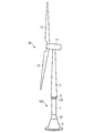
図1は、洋上風車を支持するための本発明による支持構造を断面図で概略的に示している。支持構造1は、基礎2と、タワー3の少なくとも一部とを含んでいる。支持構造1の中心線は参照符号11で示されている。基礎2とタワー3の少なくとも一部とは、1つの部分である。これは、基礎2とタワー3の少なくとも一部とが、1つの部分から形成されている又は一体に形成されていることを意味する。言い換えれば、支持構造1の様々な部分の間に結合部は存在しない。
FIG. 1 schematically shows in cross-section a support structure according to the invention for supporting an offshore wind turbine. The support structure 1 includes a
基礎2は、下側部分4と、狭い部分5と、移行部分6とを有している。下側部分4の後に狭い部分5が続いている。狭い部分5の後に移行部分6が続いている。移行部分6の後にはタワー3若しくはタワー部分3が続いている。
The
下側部分4は、海底に少なくとも部分的に接触するように構成されている。下側部分は、洗掘を減じるために円錐形になっている。下側部分4は、多数のスカート8を有している。スカート8は下側部分4の底部に配置されている。スカート8は、洗掘の低減に適したように形成されており、支持構造1と、その下の土壌との間の結合を確実にするために下側に固定するために使用することができる。さらに、スカート8は、スカートを3つ以上のチャンパーに分割することによって基礎2を水平にするために使用することができる。
The
完成した支持構造1又は少なくとも基礎2又は基礎2の少なくとも一部、例えば下側部分4又は下側部分4の一部は、中空であることができる。中空部分又は中空部分の少なくとも一部に、土壌のようなバラストを充填することができる。図1において、完成した支持構造1は中空であり、内部に中空空間24を有している。
The completed support structure 1 or at least the
タワー3は最大直径10を有している。狭い部分は直径9を有している。タワー3の最大直径10は、狭い部分5の直径9よりも大きい。さらに、タワー3は外壁22を有しており、狭い部分5は外壁23を有している。タワー3の外壁22の厚さ12は、狭い部分5の外壁23の厚さ13よりも薄い。
The
下側部分4は、円錐形であり、底部から狭い区分5まで減少する直径を有している。移行部分6は、狭い部分5からタワー部分3まで連続的に又は段階的に増大する直径29を有している。さらに、移行部分6は、狭い部分5からタワー部分3まで増大する壁厚を有している。移行部分6の後にタワー部分3が続いている、移行部分6の上面には、プラットフォーム18が形成されている。プラットフォームは支持構造1の内部に延びている。
The
タワー3又はタワー部分3は、移行部分6に続いている底部から、風車発電機がタワー3に取り付けられる上部まで、減少する直径を有している。一般的に、タワー部分3又はタワー3は、風車、特に風車ナセルに結合可能である。
The
支持構造1が海底に適切に設置されると、狭い部分5は、波しぶきの領域に配置され、移行部分6は、最も高い波の高さよりも上方に配置される。
When the support structure 1 is properly installed on the seabed, the
支持構造1はコンクリートから成る。さらに、支持構造1は、ポストストレス提供手段、例えば、少なくとも1つのケーブル、ワイヤ、ロッド、又は構造又は支持構造1の少なくとも一部にポストストレスを提供するためのあらゆるその他の適切な手段を有している。図1において、支持構造1は、少なくとも2つのポストストレス提供ケーブル7を有している。ポストストレス提供ケーブル7は支持構造1の内部に配置されている。具体的には、ポストストレス提供ケーブルの第1の部分7aは、タワー部分3の内部の中空空間24においてタワー部分3の内部に配置されている。ポストストレス提供ケーブルの第1の部分7aは、タワー部分3の上部において又は上部の近くにおいてタワー部分3に結合されている。ポストストレス提供ケーブルの第2の部分7bは、移行部分6と、狭い部分5と、下側部分4との外壁23,25,26の内部に配置されている。ポストストレス提供ケーブルの第2の部分7bの端部は、下側部分4の底部において、例えばスカート8の近くで、下側部分4に結合されている。択一的に、ポストストレス提供ケーブル7を別の適切な形式で支持構造1に結合することができる。さらに、ポストストレス提供ケーブル7を、少なくとも部分的に支持構造1の外側に配置することができる。
The support structure 1 is made of concrete. Furthermore, the support structure 1 has post-stress providing means, for example at least one cable, wire, rod, or any other suitable means for providing post-stress to at least part of the structure or support structure 1 ing. In FIG. 1, the support structure 1 has at least two
支持構造1又は支持構造1の少なくとも一部にポストストレスが提供された場合、狭い部分5のポストストレスレベルは、タワー部分3におけるストレスレベルとは異なることができる。
If post-stress is provided to the support structure 1 or at least a part of the support structure 1, the post-stress level of the
図5は、図1の本発明の支持構造1の変化態様を概略的に示している。分かりやすくするためにスカート8は省略されている。さらに、移行部分6は、図1と比較して多少異なる形状を有している。
FIG. 5 schematically shows a variation of the support structure 1 according to the invention of FIG. The skirt 8 is omitted for the sake of clarity. Furthermore, the
図5は、ポストストレス提供ケーブル7を固定するための固定エレメント19,20,21を示している。固定エレメント21は、タワー部分3の外壁22の近くにおいてタワー部分3の上部に配置されている。固定エレメント20は移行部分6のプラットフォーム18に配置されている。ポストストレス提供ケーブルの第1の部分7aは、外壁22の近くにおけるタワー部分3の内部中空空間24において固定エレメント21から固定エレメント22まで延びている。ポストストレス提供ケーブルの第2の部分7bは、移行部分6における第2の固定エレメント20から第3の固定エレメント19まで延びている。第3の固定エレメント19は、下側部分4の外壁25の内部において下側部分4の底部の近くに配置されている。ポストストレス提供ケーブルの第2の部分7bは、狭い部分5の外壁23の内部及び/又は下側部分4の外壁25の内部に延びている。さらに、ポストストレス提供ケーブルの第2の部分7bは、移行部分6の壁部26の内部にも延びていることができる。
FIG. 5
概して、ポストストレス提供ケーブルの第1の部分7a及びポストストレス提供ケーブルの第2の部分7bに、個別にストレスを提供することができる。これは、タワー部分3と基礎2とにおけるストレスレベルが異なることができることを意味する。下側部分4と狭い部分5とにおける異なるストレスレベルを提供するために、例えば下側部分4と狭い部分5との間に付加的な固定エレメントを配置することができる。
In general, the
図2は、図1及び図5の支持構造1と僅かに異なる本発明の支持構造100の変化態様を概略的に示している。支持構造100は、狭い部分5と移行部分6との間に第1の中間部分26を有しており、かつ下側部分4と狭い部分5との間に配置された第2の中間部分27を有している点において、支持構造1と異なる。
FIG. 2 schematically shows a variation of the
図3は、本発明の風車28を部分的に斜視図で概略的に示している。風車28は、図1、図2及び図5に関連して説明した支持構造100を有している。タワー3の上部にはナセル14が取り付けられている。ナセル14は、複数のロータ翼15を備えるロータを有している。風車は、通常、2つ又は3つのロータ翼15を有している。
FIG. 3 schematically shows in partial perspective a
図4は、設置船16に固定された、図3の本発明の風車28を示している。海面は参照符号17によって示されている。設置船16は、持上げクレーンを備えたカタマラン浮きクレーンを含んでよい。例えば、設置船16は、持上げクレーン又は回転クレーンを支持する巨大なフレームによって結合された、2つの自己推進式はしけを含んでよい。この場合、洋上での作業は、予め設置及び試験された風車を備えた支持構造の搬送及び配置のみを含む最小限の作業に減じられている。
FIG. 4 shows the
1 支持構造、 2 基礎、 3 タワー、 4 下側部分、 5 狭い部分、 6 移行部分、 8 スカート、 7,7a,7b ポストストレス提供ケーブル、 9 直径、 10 最大直径、 12,13 厚さ、 18 プラットフォーム、 20 固定エレメント、 21 固定エレメント、 23 外壁、 24 中空空間、 25,26 外壁、 26,27 中間部分、 28 風車、 29 増大する直径、 100 支持構造 1 support structure, 2 foundation, 3 tower, 4 lower part, 5 narrow part, 6 transition part, 8 skirt, 7, 7a, 7b post-stress providing cable, 9 diameter, 10 maximum diameter, 12, 13 thickness, 18 Platform, 20 fixing element, 21 fixing element, 23 outer wall, 24 hollow space, 25, 26 outer wall, 26, 27 middle part, 28 windmill, 29 increasing diameter, 100 support structure
Claims (15)
Applications Claiming Priority (2)
| Application Number | Priority Date | Filing Date | Title |
|---|---|---|---|
| EP10152435A EP2354536A1 (en) | 2010-02-02 | 2010-02-02 | Support structure for supporting an offshore wind turbine |
| EP10152435.3 | 2010-02-02 |
Publications (2)
| Publication Number | Publication Date |
|---|---|
| JP2011157971A true JP2011157971A (en) | 2011-08-18 |
| JP2011157971A5 JP2011157971A5 (en) | 2013-12-19 |
Family
ID=42668599
Family Applications (1)
| Application Number | Title | Priority Date | Filing Date |
|---|---|---|---|
| JP2011021071A Pending JP2011157971A (en) | 2010-02-02 | 2011-02-02 | Support structure for supporting offshore wind turbine |
Country Status (6)
| Country | Link |
|---|---|
| US (1) | US20110188945A1 (en) |
| EP (1) | EP2354536A1 (en) |
| JP (1) | JP2011157971A (en) |
| CN (1) | CN102213193A (en) |
| CA (1) | CA2730672A1 (en) |
| NZ (1) | NZ590831A (en) |
Cited By (2)
| Publication number | Priority date | Publication date | Assignee | Title |
|---|---|---|---|---|
| KR101387741B1 (en) * | 2012-07-27 | 2014-04-21 | 삼성중공업 주식회사 | Tower structure of wind turbine |
| KR101447108B1 (en) * | 2012-09-20 | 2014-10-06 | 한국해양과학기술원 | Supporting structure for offshore wind power generator |
Families Citing this family (10)
| Publication number | Priority date | Publication date | Assignee | Title |
|---|---|---|---|---|
| US20120012727A1 (en) * | 2009-03-19 | 2012-01-19 | Telefonaktiebolaget Lm Ericsson (Publ) | Tubular Telecom Tower Structure |
| CN103124823B (en) * | 2010-07-13 | 2016-05-04 | 安德森塔沃森有限公司 | Use the method for nipple assembling tubular construction structure |
| US9856621B2 (en) | 2013-09-09 | 2018-01-02 | Dbd Systems, Llc | Method of construction, installation, and deployment of an offshore wind turbine on a concrete tension leg platform |
| NO2765895T3 (en) * | 2014-02-06 | 2018-08-04 | ||
| CN106014873B (en) * | 2016-06-15 | 2018-09-11 | 江苏金风科技有限公司 | The protective device on offshore wind turbine generator system tower basis |
| CN107740753B (en) * | 2017-10-20 | 2024-03-15 | 中交三航(上海)新能源工程有限公司 | Offshore wind generating set integral installation lower part positioning system and flexible installation system for single pile foundation |
| CN113026803B (en) * | 2019-12-09 | 2023-02-28 | 中国电建集团华东勘测设计研究院有限公司 | Suction bucket-pile foundation composite structure applied to offshore electrical platform and construction method |
| GB2605377B (en) * | 2021-03-29 | 2023-11-29 | Equinor Energy As | Foundation for an offshore wind turbine |
| WO2023006955A1 (en) * | 2021-07-30 | 2023-02-02 | Lak Mohammad Amin | Gravity based foundation |
| CN117028157B (en) * | 2023-10-09 | 2023-12-15 | 中国电力工程顾问集团有限公司 | Method for installing mud floating type offshore wind turbine system |
Citations (3)
| Publication number | Priority date | Publication date | Assignee | Title |
|---|---|---|---|---|
| JP2000283019A (en) * | 1999-03-31 | 2000-10-10 | Pc Bridge Co Ltd | Concrete windmill support tower and its construction method |
| EP1777348A1 (en) * | 2005-10-21 | 2007-04-25 | Dredging International N.V. | Device and method for offshore installations |
| WO2010006659A1 (en) * | 2008-07-15 | 2010-01-21 | Siemens Aktiengesellschaft | Method for the assembly of a tower and tower |
Family Cites Families (27)
| Publication number | Priority date | Publication date | Assignee | Title |
|---|---|---|---|---|
| US3738113A (en) * | 1971-10-14 | 1973-06-12 | Chicago Bridge & Iron Co | Offshore oil storage structure with submergence shell |
| US3793840A (en) * | 1971-10-18 | 1974-02-26 | Texaco Inc | Mobile, arctic drilling and production platform |
| US3733834A (en) * | 1972-05-01 | 1973-05-22 | L Ludwig | Dynamic damper for offshore structures |
| FR2355958A2 (en) * | 1976-06-24 | 1978-01-20 | Doris Dev Richesse Sous Marine | PLATFORM STRUCTURE FOR INSTALLATION AT SEA |
| US4222682A (en) * | 1976-06-30 | 1980-09-16 | Enterprise D'equipments Mechaniques Et Hydrauliques, E.M.H. | Platforms for sea-bottom exploitation |
| US4272929A (en) * | 1979-08-23 | 1981-06-16 | Hanson Bror H | Tower and method of construction |
| GB8328404D0 (en) * | 1983-10-24 | 1983-11-23 | Dixon R K | Concrete construction |
| JPS61146909A (en) * | 1984-12-20 | 1986-07-04 | Takenaka Komuten Co Ltd | Gravity type off-shore structure and method of stably installing the same |
| NO850517L (en) * | 1985-02-12 | 1986-08-13 | Saga Petroleum | CONSTRUCTION GEOMETRY AND SHAPE FOR OFFSHORE CONCRETE PLATFORM. |
| US4639167A (en) * | 1985-04-24 | 1987-01-27 | Odeco, Inc. | Deep water mobile submersible arctic structure |
| NO164116C (en) * | 1985-10-23 | 1990-08-29 | Norwegian Contractors | FRATELAND PLATFORM CONSTRUCTION. |
| US4767241A (en) * | 1985-11-13 | 1988-08-30 | Wells Gordon T | Method for simultaneous forming of concrete footings and piers |
| IT1188547B (en) * | 1986-02-05 | 1988-01-14 | Tecnocompositi Spa | FLEXIBLE COLUMN IN COMPOSITE MATERIAL |
| IT1195882B (en) * | 1986-07-29 | 1988-10-27 | Antonio Ferruccio | PREFABRICATED COMPOSITE ELEMENT FOR THE FORMATION OF BREAKFAST BARRIERS |
| BR9103728A (en) * | 1991-08-29 | 1993-03-30 | Petroleo Brasileiro Sa | SYSTEM FOR SUPPORTING LINES AND CONDUCTING PIPES ON MARITIME PLATFORMS |
| JPH0774498B2 (en) * | 1992-03-24 | 1995-08-09 | 株式会社アスク研究所 | Method of forming cast-in-place concrete pile |
| US5316413A (en) * | 1992-09-28 | 1994-05-31 | Chevron Research And Technology Company | Offshore double cone structure |
| US5433557A (en) * | 1993-12-27 | 1995-07-18 | Spencer, White & Prentis Foundation Corporation | Method for underpinning an existing footing |
| US5513929A (en) * | 1994-08-11 | 1996-05-07 | Mcdermott International, Inc. | Fixed offshore platform structures, using small diameter, tensioned, well casing tiebacks |
| US5960597A (en) * | 1996-10-24 | 1999-10-05 | Schwager Davis, Inc. | Method for post-tensioning columns |
| US6371695B1 (en) * | 1998-11-06 | 2002-04-16 | Exxonmobil Upstream Research Company | Offshore caisson having upper and lower sections separated by a structural diaphragm and method of installing the same |
| GB0020410D0 (en) * | 2000-08-19 | 2000-10-04 | Ocean Technologies Ltd | Offshore windtower |
| DE10126912A1 (en) * | 2001-06-01 | 2002-12-19 | Oevermann Gmbh & Co Kg Hoch Un | Prestressed concrete tower structure |
| FR2872843B1 (en) * | 2004-07-12 | 2006-10-06 | Electricite De France | METHOD FOR CONSTRUCTING A LONGITUDINAL MATERIAL IN CONCRETE, TUBULAR ELEMENT FOR ITS USE AND MATT OBTAINED |
| ES2246734B1 (en) * | 2005-04-21 | 2007-04-16 | STRUCTURAL CONCRETE & STEEL, S.L. | PREFABRICATED MODULAR TOWER. |
| US7367780B2 (en) * | 2005-09-30 | 2008-05-06 | General Electric Company | System and method for driving a monopile for supporting an offshore wind turbine |
| WO2009097355A2 (en) * | 2008-01-28 | 2009-08-06 | Kruse Darin R | Apparatus and methods for underground structures and construction thereof |
-
2010
- 2010-02-02 EP EP10152435A patent/EP2354536A1/en not_active Withdrawn
-
2011
- 2011-01-28 CN CN2011100311628A patent/CN102213193A/en active Pending
- 2011-01-31 CA CA2730672A patent/CA2730672A1/en not_active Abandoned
- 2011-01-31 NZ NZ590831A patent/NZ590831A/en not_active IP Right Cessation
- 2011-02-01 US US13/018,687 patent/US20110188945A1/en not_active Abandoned
- 2011-02-02 JP JP2011021071A patent/JP2011157971A/en active Pending
Patent Citations (3)
| Publication number | Priority date | Publication date | Assignee | Title |
|---|---|---|---|---|
| JP2000283019A (en) * | 1999-03-31 | 2000-10-10 | Pc Bridge Co Ltd | Concrete windmill support tower and its construction method |
| EP1777348A1 (en) * | 2005-10-21 | 2007-04-25 | Dredging International N.V. | Device and method for offshore installations |
| WO2010006659A1 (en) * | 2008-07-15 | 2010-01-21 | Siemens Aktiengesellschaft | Method for the assembly of a tower and tower |
Cited By (2)
| Publication number | Priority date | Publication date | Assignee | Title |
|---|---|---|---|---|
| KR101387741B1 (en) * | 2012-07-27 | 2014-04-21 | 삼성중공업 주식회사 | Tower structure of wind turbine |
| KR101447108B1 (en) * | 2012-09-20 | 2014-10-06 | 한국해양과학기술원 | Supporting structure for offshore wind power generator |
Also Published As
| Publication number | Publication date |
|---|---|
| EP2354536A1 (en) | 2011-08-10 |
| CN102213193A (en) | 2011-10-12 |
| CA2730672A1 (en) | 2011-08-02 |
| NZ590831A (en) | 2012-03-30 |
| US20110188945A1 (en) | 2011-08-04 |
Similar Documents
| Publication | Publication Date | Title |
|---|---|---|
| JP2011157971A (en) | Support structure for supporting offshore wind turbine | |
| US11352098B2 (en) | Method of assembling a floating wind turbine platform | |
| KR102155394B1 (en) | Floating offshore wind power generation facility | |
| EP2836708B1 (en) | Floating wind turbine platform and method of assembling | |
| US9592889B2 (en) | Submersible active support structure for turbine towers and substations or similar elements, in offshore facilities | |
| KR101189681B1 (en) | A support apparatus for sea wind power generator | |
| US20170159260A1 (en) | Offshore support structure, offshore tower installation with the offshore support structure and offshore wind power plant with the offshore tower installation | |
| US9771700B2 (en) | Structures for offshore installations | |
| CN208763050U (en) | Offshore wind turbine gravity caisson basis | |
| JP2012201218A (en) | Method for constructing offshore wind power generation facility | |
| GB2505192A (en) | A pile sleeve connection for a monopole foundation | |
| US20240084537A1 (en) | Portal frame platform and construction method for large offshore wind turbines | |
| CN114180469A (en) | Offshore wind power hoisting tower crane and mounting base thereof | |
| BR112016017971B1 (en) | FLOATING WIND TURBINE FARM |
Legal Events
| Date | Code | Title | Description |
|---|---|---|---|
| A521 | Written amendment |
Free format text: JAPANESE INTERMEDIATE CODE: A523 Effective date: 20131106 |
|
| A621 | Written request for application examination |
Free format text: JAPANESE INTERMEDIATE CODE: A621 Effective date: 20131106 |
|
| A977 | Report on retrieval |
Free format text: JAPANESE INTERMEDIATE CODE: A971007 Effective date: 20141017 |
|
| A02 | Decision of refusal |
Free format text: JAPANESE INTERMEDIATE CODE: A02 Effective date: 20150330 |