CN102213193A - Support structure for supporting an offshore wind turbine - Google Patents
Support structure for supporting an offshore wind turbine Download PDFInfo
- Publication number
- CN102213193A CN102213193A CN2011100311628A CN201110031162A CN102213193A CN 102213193 A CN102213193 A CN 102213193A CN 2011100311628 A CN2011100311628 A CN 2011100311628A CN 201110031162 A CN201110031162 A CN 201110031162A CN 102213193 A CN102213193 A CN 102213193A
- Authority
- CN
- China
- Prior art keywords
- supporting structure
- tower
- post
- narrow section
- stressing
- Prior art date
- Legal status (The legal status is an assumption and is not a legal conclusion. Google has not performed a legal analysis and makes no representation as to the accuracy of the status listed.)
- Pending
Links
Images


Classifications
-
- F—MECHANICAL ENGINEERING; LIGHTING; HEATING; WEAPONS; BLASTING
- F03—MACHINES OR ENGINES FOR LIQUIDS; WIND, SPRING, OR WEIGHT MOTORS; PRODUCING MECHANICAL POWER OR A REACTIVE PROPULSIVE THRUST, NOT OTHERWISE PROVIDED FOR
- F03D—WIND MOTORS
- F03D13/00—Assembly, mounting or commissioning of wind motors; Arrangements specially adapted for transporting wind motor components
- F03D13/10—Assembly of wind motors; Arrangements for erecting wind motors
-
- E—FIXED CONSTRUCTIONS
- E02—HYDRAULIC ENGINEERING; FOUNDATIONS; SOIL SHIFTING
- E02B—HYDRAULIC ENGINEERING
- E02B17/00—Artificial islands mounted on piles or like supports, e.g. platforms on raisable legs or offshore constructions; Construction methods therefor
- E02B17/0004—Nodal points
-
- E—FIXED CONSTRUCTIONS
- E02—HYDRAULIC ENGINEERING; FOUNDATIONS; SOIL SHIFTING
- E02B—HYDRAULIC ENGINEERING
- E02B17/00—Artificial islands mounted on piles or like supports, e.g. platforms on raisable legs or offshore constructions; Construction methods therefor
- E02B2017/0056—Platforms with supporting legs
- E02B2017/0073—Details of sea bottom engaging footing
- E02B2017/0082—Spudcans, skirts or extended feet
-
- E—FIXED CONSTRUCTIONS
- E02—HYDRAULIC ENGINEERING; FOUNDATIONS; SOIL SHIFTING
- E02B—HYDRAULIC ENGINEERING
- E02B17/00—Artificial islands mounted on piles or like supports, e.g. platforms on raisable legs or offshore constructions; Construction methods therefor
- E02B2017/0091—Offshore structures for wind turbines
-
- Y—GENERAL TAGGING OF NEW TECHNOLOGICAL DEVELOPMENTS; GENERAL TAGGING OF CROSS-SECTIONAL TECHNOLOGIES SPANNING OVER SEVERAL SECTIONS OF THE IPC; TECHNICAL SUBJECTS COVERED BY FORMER USPC CROSS-REFERENCE ART COLLECTIONS [XRACs] AND DIGESTS
- Y02—TECHNOLOGIES OR APPLICATIONS FOR MITIGATION OR ADAPTATION AGAINST CLIMATE CHANGE
- Y02E—REDUCTION OF GREENHOUSE GAS [GHG] EMISSIONS, RELATED TO ENERGY GENERATION, TRANSMISSION OR DISTRIBUTION
- Y02E10/00—Energy generation through renewable energy sources
- Y02E10/70—Wind energy
- Y02E10/72—Wind turbines with rotation axis in wind direction
Landscapes
- Engineering & Computer Science (AREA)
- General Engineering & Computer Science (AREA)
- Mechanical Engineering (AREA)
- Civil Engineering (AREA)
- Structural Engineering (AREA)
- Life Sciences & Earth Sciences (AREA)
- Sustainable Development (AREA)
- Sustainable Energy (AREA)
- Chemical & Material Sciences (AREA)
- Combustion & Propulsion (AREA)
- Wind Motors (AREA)
Abstract
A support structure (1, 100) for supporting offshore wind turbines is provided. It comprises a foundation (2) configured to at least partly contact a seabed and at least part of a tower (3). The foundation (2) and the at least part of the tower (3) are one-piece.
Description
Technical field
The present invention relates to be used to support the supporting structure of offshore wind turbine.The invention further relates to wind turbine.
Background technique
The pedestal of offshore wind turbine is divided into three groups usually, i.e. gravity base, single pile pedestal and the advanced pedestal such as tripod pedestal or suction bucket pedestal.
Gravity base is made by mixed earth usually.They can be formed into hollow and have enough buoyancy so that floating in place, may support with buoyancy elements, and perhaps they can and be raised in place by barging.The weight of pedestal self increases the heavy ballast such as olivine owing to adopting heavy ballast to carry out ballast usually.The shortcoming of gravity base is when large-scale turbo machine and/or the depth of water are very big, and they tend to become very expensive.
The single pile pedestal is made up of piling bar, and this piling bar has the diameter of 4-5 rice usually.Depend on underground type, stake is driven into about 20~30 meters of sea bed.The single pile pedestal extends under water and enters sea bed effectively with turbine tower.
A significant advantage of this pedestal is and needn't prepares sea bed.On the other hand, it needs heavy pile driving equipment, and this pedestal type is not suitable for being used in the position that has many big rocks in the sea bed.And when large-scale turbo machine and/or the depth of water were very big, it tended to become very expensive.
The marine pedestal of modal advanced person is the tripod pedestal.Such pedestal has absorbed experience, thereby utilizes the tripodia steel sheath of light weight and cost savings, and it is used for the coastal waters marginal oil field of oil industry.This structure is made up of center tube and three foots that tilt usually.Three foots connect in the bottom and also are connected to center tube.In each sufficient end, use short vertical tube as sheath around piling bar, this piling bar is driven dearly to be entered in the sea bed.After finishing piling, high-strength mortar is injected sheath, thereby form the firm connection between stake and the foot.
The shortcoming of steel tripod is that they are physically very large structures and have high request, complicated, the tired soldering point that loads.Therefore, they tend to very expensive.
Commonly, when being installed in the wind farm place, the pedestal structure that supports wind turbine tower stretches out on the water surface for used these of offshore wind turbine and other known pedestals of great majority.Owing to tangible reason, the undersea joint construction that comprises fastening piece (bolt etc.) may be a difficulty and dangerous.
Disclosed pedestal is an exception among the EP1884598.Disclose a kind of marine pedestal in EP1884598, it comprises stake and superstructure.This quilt rams in the sea bed downwards and only stretch out limited elongation on sea bed.The stake provide the base posts that is used for superstructure, this superstructure be fastened to the stake the top on.Here, problem is to set up the joint between stake and the superstructure, and one usually by injecting the task that high-strength mortar is finished.
Commonly, because the external loading on the turbo machine can be from all directions, so the bearing part of structure will be usually located at any certain portions of giving of pedestal, experience is compressed and tension load for nearly all marine pedestal.In addition, the stress that brings of operating load will change between compressive stress and tensile stress usually back and forth.
For this reason, steel has become preferred material, and this is because it is worked under the fluctuating stress condition well.And the advantage that steel also has is that the intensity of unit mass is significantly better than for example concrete.Therefore, tower is formed from steel usually, to allow road transport.Yet, compare cement, steel has three major defects.The first, the price for intensity is obviously higher, and is subjected to the influence of economic fluctuation to a great extent.The second, for the steel in the wind turbine, fatigue usually is the driving force of design, and limit load is for cement here.Therefore, if handle appropriately, concrete towers or pedestal have the longer life-span naturally.The 3rd, steel requires very careful surface treatment, to avoid the corrosion in ocean environment.
Single pile and wind turbine generator are mounted with the form of part usually, comprise from rising ship (for example single pile rise certainly ship), transition piece, a 2-3 tower section, cabin and blade.Usually come mounting base and wind turbine generator with two steps, therefore have on each wind turbine generator position, install twice from rising ship.Because turbo machine is marine assembling, so expended time and labor hour on the expensive ship, complete test is difficulty and necessary marine the execution more.In addition, rising ship certainly is advanced equipment spare.For example, it has expensive system that rises certainly and the large-scale revolving crane that comprises a plurality of motion parts.
Disclosed pedestal is an exception among the EP1058787, and wherein, tower is made by module, and these modules are utilized the after-drawing cable and remained in compressive state.Here, shortcoming is such as suitable corrosion-vulnerable of the high tensile steel that is used for the after-drawing cable and hydrogen embrittlement.Therefore, the long-term integrity that is inserted into the after-drawing cable in the passage in the structure outer wall that is installed in b.s.l. may be debatable.
Summary of the invention
First purpose of the present invention provides favourable supporting structure, is used to support offshore wind turbine.Second purpose of the present invention provides favourable wind turbine.
By realizing first purpose as claim 1 supporting structure that is used to support offshore wind turbine required for protection.By realizing second purpose as claim 15 wind turbine required for protection.Dependent claims defines of the present invention further developing.
The supporting structure that is used to support offshore wind turbine of the present invention comprises at least a portion of the pedestal and the tower that are configured to contact at least in part sea bed.At least a portion of this pedestal and tower is a single-piece.Such advantage is no longer to need to spend cost tower is fastened on the pedestal.
In the context of the present invention, single-piece means that the part of pedestal and tower or tower is integrally formed or is formed by single member.At last, between the part of pedestal and tower or tower, do not have connection set, perhaps between the different sections of pedestal, do not have connection set.
At least a portion as the tower of the part of supporting structure of the present invention is also referred to as the tower section.Tower or tower section can be connected to wind turbine generator, particularly are connected to the wind turbine cabin.
Pedestal can comprise narrow section, and the diameter of this narrow section is less than the maximum diameter of tower.Preferably, when supporting structure was installed on the sea bed, narrow section can be positioned at the wave of ocean and pat the zone.Narrow section is such fact than tower or the narrower benefit of tower section: narrow section is exposed to the wave load, and tower or tower section are exposed to wind load.Tower or tower section make that than major diameter the structure of tower is firmer.
Advantageously, supporting structure can comprise concrete and/or steel.For example, it can comprise the concrete of 45 Mpa or 30 Gpa types.Concrete advantage is that it is relatively cheap material.Therefore, the cost of pedestal and wind turbine can be reduced.
In addition, pedestal can comprise transition zone and/or the lower curtate with diameter change.Lower curtate can be configured to contact at least in part sea bed.Preferably, lower curtate can be conical to small part, for example washes away reducing.Transition zone can be between narrow section and tower or tower section.When supporting structure was installed on the sea bed, transition zone can be advantageously located on the highest wave height.Preferably, the diameter of transition zone for example increases continuously or progressively from narrow section to the tower section, thereby uses the diameter greater than narrow segment diameters to form platform and/or come support tower.Usually, transition zone can have the diameter bigger than narrow section.Transition zone can be used for promoting during installation supporting structure.
Tower or tower section can comprise outer wall.Narrow section also can comprise outer wall.Advantageously, the outer wall of comparable tower of the outer wall of narrow section or tower section is thicker.
Advantageously, at least a portion of supporting structure can be by post-stressing.Post-stressing can be used for reducing tensile stress, especially in concrete at least a portion.For example, the post-stressing level in the narrow section can be different from the stress level in the tower.In this article, the post-stressing level mean the tension, activate or add torque in add answer power apparatus after, the stress in the specified structure element.Add and answer power apparatus can refer to for example cable, rod or filament.In the different sections of supporting structure, provide different stress levels, thereby consider and make particular stress level be suitable for certain environmental conditions.For example, below the sea level and above, different stress levels may be favourable.
Usually, supporting structure can comprise at least one post-stressing device and/or at least one after-drawing stiffening device, for example cable, filament or rod.At least one post-stressing device and/or at least one after-drawing stiffening device can be placed on the inside of the wall of supporting structure inside or supporting structure, and perhaps the side along structure is positioned at the outside.Post-stressing in lower curtate and the narrow section can apply in supporting structure inside, for example in concrete support structure inside.Post-stressing in tower or the tower section can apply in the outside of outer wall at least in part, and this outer wall can be a concrete wall, for example in tower or tower section inside.
At least one post-stressing device and/or at least one after-drawing stiffening device can be placed in the tower or in the tower section, and be outside and/or in tower or tower section inside at outer wall at least in part.In addition, at least one post-stressing device and/or at least one after-drawing stiffening device can be placed in the lower curtate, at the outer pars intramuralis of lower curtate.
And at least one post-stressing device and/or at least one after-drawing stiffening device can be placed in the narrow section, at the outer pars intramuralis of narrow section.
Preferably, the post-stressing device in tower or the tower section can be connected to the post-stressing device in the transition zone, and/or is connected to the post-stressing device in the narrow section, and/or is connected to the post-stressing device in the lower curtate.In addition, the post-stressing device in the transition zone can be connected to the post-stressing device in the narrow section, and/or is connected to the post-stressing device in the lower curtate.Post-stressing device in the narrow section can be connected to the post-stressing device in the lower curtate.
After-drawing is strengthened applying in the conduit of concrete structure or is externally applied along the side of structure.Combine with inner after-drawing, Corrugated Steel or at least one plastic catheter can be cast in the concrete structure, have anchor at its two ends.Filament can be hauled passes conduit, and is stretched by means of for example hydraulic tensioning sheath.But fill the protection thing in the conductive pipe.Preferably, the high strength cement of expansion slurry can be used for cable is locked onto by the catheter wall in the concrete structure of casting.Can adopt other protective materials, for example grease or wax, the two all allows extra stretching, and this is an optimal way of handling the lax and concrete deformation in the steel wire.The inner advantage of strengthening being had is that the stretching filament has obtained excellent protection in the inside of concrete wall, especially protected moisture, grease or the wax that avoids cement slurry.Outside after-drawing filament can have plastic sheath and/or be protected by grease.Preferably, outside after-drawing wire can be positioned over the cement structures next door.
In a preferred embodiment, pedestal is by inner post-stressing, and conduit can be filled with protective material, and for example cement slurry, grease or wax are used for corrosion protection.The after-drawing of tower section can be by inner post-stressing.Filament can be connected to anchor, is used for the pedestal post-stressing.Preferably, the after-drawing filament that is used for base part is pulled by the bottom from structure, and added stress to this level to minimize hoist work, platform and scaffold layout.
Advantageously, lower curtate and/or narrow section and/or transition zone and/or tower or tower section are hollow.In this case, at least a portion of supporting structure can be filled with ballast, for example earth.This has increased the stability of supporting structure under load.
Lower curtate can comprise for example at least one skirt section, with fixing of provide the structural support and sea bed.And, this skirt section can be configured to reduce wash away or below cement slurry filling so that being connected firmly between supporting structure and the bottom soil.In addition, this skirt section can be divided into 3 or more a plurality of chamber (champer).It can be used for making base level.
Usually, Soil Interface can be dark or shallow pedestal.Dark pedestal can comprise one or more stakes.The shallow foundation seat can be gravity base or inhale the bucket pedestal.Gravity base can be shaped on the skirt section to reduce the requirement of the seabed being prepared and/or washing away protection.The gravity base that does not have the skirt section is preferred.
Wind turbine of the present invention, especially offshore wind turbine comprise foregoing supporting structure of the present invention.Wind turbine of the present invention has the advantage identical with supporting structure of the present invention.
All parts of supporting structure of the present invention or wind turbine of the present invention can be made near the mobile production line of the position harbour.The hasp reinforcer can be enhanced on the revolution model and makes in advance by the rolling net or by rotation.Can use the shaping (jumpforming) of jumping to obtain favorable surface quality.
Can install by floating crane.For place far away, can carry out barging.Floating crane can be formed into twin hull ship, and it promotes on the center, does not need mobile ballast thus when promoting.In addition, floating crane can be formed into has ballast tank, allows to make during installation the more parts submergence of floating crane, to obtain stability.For barging, extensible mobile production line is to be loaded into complete turbo machine on the transport barge.
An advantage of supporting structure of the present invention and wind turbine of the present invention is a described supporting structure and/or described wind turbine Installation And Test on the coast.Wind turbine and pedestal can be installed at once.Because the low-quality relatively cause of structure is so this is possible.On the installation ship, do not need from rising system.On the installation ship, do not need the huge revolving hoist.Because selected material is a concrete by it, does not need supporting structure is safeguarded or a little maintenance.The life-span of supporting structure may reach the life-span of collecting system, and it is about 60 years.Mobile production line can produce more industrialized production.Localized production can produce local working opportunity, and this can become policymaker's Consideration.This structure be rigidity and therefore have potentiality of the darker water of opposing.Can use cheap concrete, for example 45 Mpa and 30 Gpa.Therefore, the invention provides offshore wind turbine pedestal and tower and offshore wind turbine cheaply cheaply.
Description of drawings
From following description and in conjunction with the accompanying drawings to embodiment, other features of the present invention, character and advantage will become clear.
Fig. 1 schematically shows supporting structure of the present invention with sectional view.
Fig. 2 schematically shows the variant of supporting structure of the present invention.
Fig. 3 schematically shows wind turbine of the present invention.
Fig. 4 schematically shows wind turbine of the present invention and ship is installed.
Fig. 5 schematically shows the supporting structure with post-stressing cable of the present invention.
Embodiment
Now with reference to Fig. 1 to Fig. 5 one embodiment of the present of invention are described.
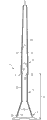
Fig. 1 schematically shows the supporting structure that is used to support offshore wind turbine of the present invention with sectional view.Supporting structure 1 comprises at least a portion 3 of pedestal 2 and tower.The center line of supporting structure 1 is represented with reference character 11.At least a portion 3 of pedestal 2 and tower is single-pieces.That at least a portion 3 that this means pedestal 2 and tower is made into single-piece or integrally formed.In other words, between the different sections of supporting structure 1, do not connect.
Whole supporting structure 1, perhaps pedestal 2 at least, perhaps at least a portion of pedestal 2 (for example part of lower curtate 4 or lower curtate 4) can be hollow.At least a portion of hollow parts or hollow section can be filled with the ballast such as earth.In Fig. 1, whole supporting structure is hollow, and it comprises inner hollow space 24.
When supporting structure 1 suitably was installed on the sea bed, narrow section 5 was positioned at wave and pats the zone, and transition zone 6 is positioned on the highest wave level height.
Supporting structure 1 comprises concrete.In addition, supporting structure 1 comprises the post-stressing device, and for example at least one cable, filament, rod or any other are suitable is used for the post-stressed device of at least a portion to structure or supporting structure 1.In Fig. 1, supporting structure 1 comprises at least two post-stressing cables 7.Post-stressing cable 7 is placed on supporting structure 1 inside.More specifically, the 7a of first portion of post-stressing cable is positioned at tower section 3 inside, in the hollow space 24 of tower section 3 inside.The 7a of first portion of post-stressing cable on the top of tower section 3 or near be connected to tower section 3.The second portion 7b of post-stressing cable is positioned at the inside of the outer wall 23,25,26 of transition zone 6, narrow section 5 and lower curtate 4.The end of the second portion 7b of post-stressing cable is connected to lower curtate 4 in the bottom of lower curtate 4, for example near skirt section 8.Alternatively, post-stressing cable 7 can be connected to supporting structure 1 by another kind of suitable method.And post-stressing cable 7 can be positioned at the outside of supporting structure 1 at least in part.
When at least a portion of supporting structure 1 or supporting structure 1 during by post-stressing, the post-stressing level in the narrow section 5 can be different from the stress level in the tower section 3.
Fig. 5 schematically shows the variant of the supporting structure of the present invention of Fig. 1.Omitted skirt section 8 for the sake of simplicity.And, compare Fig. 1, transition zone 6 has different slightly shapes.
Fig. 5 shows fixed element 19,20 and 21, is used for fixing post-stressing cable 7.Fixed element 21 is positioned on tower section 3 tops, near the outer wall 22 of tower section 3.Fixed element 20 is positioned at platform 18 places of transition zone 6.The 7a of first portion of post-stressing cable extends to fixed element 22 from fixed element 21, and fixed element 22 is in the interior hollow space 24 of tower section 3, near outer wall 22.The second portion 7b of post-stressing cable extends to the 3rd fixed element 19 from second fixed element 20 of transition zone 6.The 3rd fixed element 19 is positioned at the bottom near lower curtate 4, in outer wall 25 inside of lower curtate 4.The second portion 7b of post-stressing cable extends in outer wall 23 inside of narrow section 5 and/or in outer wall 25 inside of lower curtate 4.And the second portion 7b of post-stressing cable also can be wall 26 inner extensions of transition zone 6.
Usually, the second portion 7b of the 7a of first portion of post-stressing cable and post-stressing cable can be added stress respectively.This means that tower section 3 and the stress level in the pedestal 2 can be different.For example, other fixed element can be placed between lower curtate 4 and the narrow section 5, so that the different stress levels in lower curtate 4 and the narrow section 5 to be provided.
Fig. 2 schematically shows the variant of supporting structure 100 of the present invention, and it is different from the supporting structure 1 of Fig. 1 and Fig. 5 slightly.Supporting structure 100 is that with the different of supporting structure 1 it comprises first centre portion 26 between narrow section 5 and transition zone 6, and second centre portion 27 between lower curtate 4 and narrow section 5.
Fig. 3 schematically shows wind turbine 28 of the present invention with the part perspective view.Wind turbine 28 comprises in conjunction with Fig. 1, Fig. 2 and the described supporting structure 100 of Fig. 5.Cabin 14 is installed on tower 3 tops.Cabin 14 comprises the rotor with a plurality of rotor blades 15.Wind turbine generally includes two or three rotor blades 15.
Fig. 4 schematically shows the wind turbine of the present invention 28 of Fig. 3, and it is fixed to installs ship 16.The sea level is by reference character 17 expressions.Ship 16 is installed is comprised unsteady twin hull ship hoist with hoisting crane.For example, ship 16 is installed can be comprised two self-propelled barges, it can be connected by the mega-frame that has carried lifting or isolated pillar crane.In this case, marine work is reduced to minimum, only comprises transportation and the supporting structure of placing the wind turbine with pre-installation and test.
Claims (15)
1. supporting structure (1,100) that is used to support offshore wind turbine, comprise the pedestal (2) that is configured to contact at least in part sea bed and at least a portion of tower (3), wherein, at least a portion of described pedestal (2) and described tower (3) is a single-piece.
2. supporting structure as claimed in claim 1 (1,100) is characterized in that, described supporting structure (1,100) comprises concrete and/or steel.
3. supporting structure as claimed in claim 1 or 2 (1,100), it is characterized in that, described pedestal (2) comprises narrow section (5) and/or lower curtate (4) and/or transition zone (6), the diameter (9) of described narrow section (5) is less than the maximum diameter (10) of described tower (3), and described transition zone (6) has diameter change (29).
4. supporting structure as claimed in claim 3 (1,100) is characterized in that, described transition zone (6) is positioned between described narrow section (5) and the described tower (3).
5. as each described supporting structure (1,100) in the claim 1 to 4, it is characterized in that described supporting structure (1,100) comprises transition zone (6), the diameter of described transition zone (6) is greater than the diameter of described narrow section (5).
6. as each described supporting structure (1,100) in the claim 1 to 5, it is characterized in that, described tower (3) comprises outer wall (22), and described narrow section (5) comprises outer wall (23), and the outer wall (23) of described narrow section (5) is thicker than the outer wall (22) of described tower (3).
7. as each described supporting structure (1,100) in the claim 1 to 6, it is characterized in that at least a portion of described supporting structure (1,100) is by post-stressing.
8. supporting structure as claimed in claim 7 (1,100) is characterized in that the post-stressing level in the described narrow section (5) is different from the stress level in the described tower (3).
9. as each described supporting structure (1,100) in the claim 1 to 8, it is characterized in that described supporting structure (1,100) comprises at least one post-stressing device (7,19,20,21) and/or at least one after-drawing stiffening device (7,19,20,21).
10. supporting structure as claimed in claim 9 (1,100), it is characterized in that, described post-stressing device (7) and/or at least one after-drawing stiffening device (19,20,21) are placed on described supporting structure (1,100) inside, or be placed on the inside of the wall (22,23,25,26) of described supporting structure (1,100), or be positioned at the outside along the side of described structure (1,100).
11. as claim 9 or 10 described supporting structures (1,100), it is characterized in that, described post-stressing device (7) and/or at least one after-drawing stiffening device (19,20,21) are placed in the described tower (3) and are positioned at the outside of outer wall (22) at least in part, and/or be placed in the described lower curtate (4) and be positioned at outer wall (25) inside of described lower curtate (4), and/or be placed in the described narrow section (5) and be positioned at the inside of the outer wall (23) of described narrow section (5).
12. as each described supporting structure (1,100) in the claim 9 to 11, it is characterized in that, post-stressing device (7) in the described tower (3) is connected to the post-stressing device (7) in the described transition zone (6), and/or be connected to post-stressing device (7) in the described narrow section (5), and/or be connected to the post-stressing device (7) in the described lower curtate (4); And/or the post-stressing device (7) in the described transition zone (6) is connected to the post-stressing device (7) in the described narrow section (5), and/or is connected to the post-stressing device (7) in the described lower curtate (4); And/or the post-stressing device (7) in the described narrow section (5) is connected to the post-stressing device (7) in the described lower curtate (4).
13., it is characterized in that described lower curtate (4) and/or narrow section (5) and/or transition zone (6) and/or tower (3) are hollow as each described supporting structure (1,100) in the claim 1 to 12.
14., it is characterized in that described lower curtate (4) comprises at least one skirt section (8) as each described supporting structure (1,100) in the claim 1 to 13.
15. a wind turbine comprises as each described supporting structure (1,100) in the claim 1 to 14.
Applications Claiming Priority (2)
| Application Number | Priority Date | Filing Date | Title |
|---|---|---|---|
| EP10152435.3 | 2010-02-02 | ||
| EP10152435A EP2354536A1 (en) | 2010-02-02 | 2010-02-02 | Support structure for supporting an offshore wind turbine |
Publications (1)
| Publication Number | Publication Date |
|---|---|
| CN102213193A true CN102213193A (en) | 2011-10-12 |
Family
ID=42668599
Family Applications (1)
| Application Number | Title | Priority Date | Filing Date |
|---|---|---|---|
| CN2011100311628A Pending CN102213193A (en) | 2010-02-02 | 2011-01-28 | Support structure for supporting an offshore wind turbine |
Country Status (6)
| Country | Link |
|---|---|
| US (1) | US20110188945A1 (en) |
| EP (1) | EP2354536A1 (en) |
| JP (1) | JP2011157971A (en) |
| CN (1) | CN102213193A (en) |
| CA (1) | CA2730672A1 (en) |
| NZ (1) | NZ590831A (en) |
Cited By (2)
| Publication number | Priority date | Publication date | Assignee | Title |
|---|---|---|---|---|
| CN107740753A (en) * | 2017-10-20 | 2018-02-27 | 中交三航(上海)新能源工程有限公司 | A kind of offshore wind turbine integral installation bottom system in place and flexible installation system for single-pile foundation |
| CN117028157A (en) * | 2023-10-09 | 2023-11-10 | 中国电力工程顾问集团有限公司 | Method for installing mud floating type offshore wind turbine system |
Families Citing this family (11)
| Publication number | Priority date | Publication date | Assignee | Title |
|---|---|---|---|---|
| EP2408981A4 (en) * | 2009-03-19 | 2016-04-06 | Ericsson Telefon Ab L M | Tubular telecom tower structure |
| CN103124823B (en) * | 2010-07-13 | 2016-05-04 | 安德森塔沃森有限公司 | Use the method for nipple assembling tubular construction structure |
| KR101387741B1 (en) * | 2012-07-27 | 2014-04-21 | 삼성중공업 주식회사 | Tower structure of wind turbine |
| KR101447108B1 (en) * | 2012-09-20 | 2014-10-06 | 한국해양과학기술원 | Supporting structure for offshore wind power generator |
| US9856621B2 (en) | 2013-09-09 | 2018-01-02 | Dbd Systems, Llc | Method of construction, installation, and deployment of an offshore wind turbine on a concrete tension leg platform |
| NO2765895T3 (en) * | 2014-02-06 | 2018-08-04 | ||
| CN106014873B (en) * | 2016-06-15 | 2018-09-11 | 江苏金风科技有限公司 | The protective device on offshore wind turbine generator system tower basis |
| CN113026803B (en) * | 2019-12-09 | 2023-02-28 | 中国电建集团华东勘测设计研究院有限公司 | Suction bucket-pile foundation composite structure applied to offshore electrical platform and construction method |
| JP2021195754A (en) * | 2020-06-11 | 2021-12-27 | 日鉄エンジニアリング株式会社 | Marine gravity-based foundation |
| GB2605377B (en) * | 2021-03-29 | 2023-11-29 | Equinor Energy As | Foundation for an offshore wind turbine |
| US20240328107A1 (en) * | 2021-07-30 | 2024-10-03 | Mohammad Amin LAK | Gravity based foundation |
Citations (6)
| Publication number | Priority date | Publication date | Assignee | Title |
|---|---|---|---|---|
| WO2000028153A1 (en) * | 1998-11-06 | 2000-05-18 | Exxonmobil Upstream Research Company | Offshore caisson |
| GB2365905A (en) * | 2000-08-19 | 2002-02-27 | Ocean Technologies Ltd | Offshore structure with a telescopically extendable column |
| EP1262614A2 (en) * | 2001-06-01 | 2002-12-04 | Oevermann GmbH & Co. KG, Hoch- und Tiefbau | Prestressed concrete tower |
| FR2872843B1 (en) * | 2004-07-12 | 2006-10-06 | Electricite De France | METHOD FOR CONSTRUCTING A LONGITUDINAL MATERIAL IN CONCRETE, TUBULAR ELEMENT FOR ITS USE AND MATT OBTAINED |
| CN1940186A (en) * | 2005-09-30 | 2007-04-04 | 通用电气公司 | System and method for driving a monopile for supporting an offshore wind turbine |
| EP1777348A1 (en) * | 2005-10-21 | 2007-04-25 | Dredging International N.V. | Device and method for offshore installations |
Family Cites Families (24)
| Publication number | Priority date | Publication date | Assignee | Title |
|---|---|---|---|---|
| US3738113A (en) * | 1971-10-14 | 1973-06-12 | Chicago Bridge & Iron Co | Offshore oil storage structure with submergence shell |
| US3793840A (en) * | 1971-10-18 | 1974-02-26 | Texaco Inc | Mobile, arctic drilling and production platform |
| US3733834A (en) * | 1972-05-01 | 1973-05-22 | L Ludwig | Dynamic damper for offshore structures |
| FR2355958A2 (en) * | 1976-06-24 | 1978-01-20 | Doris Dev Richesse Sous Marine | PLATFORM STRUCTURE FOR INSTALLATION AT SEA |
| US4222682A (en) * | 1976-06-30 | 1980-09-16 | Enterprise D'equipments Mechaniques Et Hydrauliques, E.M.H. | Platforms for sea-bottom exploitation |
| US4272929A (en) * | 1979-08-23 | 1981-06-16 | Hanson Bror H | Tower and method of construction |
| GB8328404D0 (en) * | 1983-10-24 | 1983-11-23 | Dixon R K | Concrete construction |
| JPS61146909A (en) * | 1984-12-20 | 1986-07-04 | Takenaka Komuten Co Ltd | Gravity type off-shore structure and method of stably installing the same |
| NO850517L (en) * | 1985-02-12 | 1986-08-13 | Saga Petroleum | CONSTRUCTION GEOMETRY AND SHAPE FOR OFFSHORE CONCRETE PLATFORM. |
| US4639167A (en) * | 1985-04-24 | 1987-01-27 | Odeco, Inc. | Deep water mobile submersible arctic structure |
| NO164116C (en) * | 1985-10-23 | 1990-08-29 | Norwegian Contractors | FRATELAND PLATFORM CONSTRUCTION. |
| US4767241A (en) * | 1985-11-13 | 1988-08-30 | Wells Gordon T | Method for simultaneous forming of concrete footings and piers |
| IT1188547B (en) * | 1986-02-05 | 1988-01-14 | Tecnocompositi Spa | FLEXIBLE COLUMN IN COMPOSITE MATERIAL |
| IT1195882B (en) * | 1986-07-29 | 1988-10-27 | Antonio Ferruccio | PREFABRICATED COMPOSITE ELEMENT FOR THE FORMATION OF BREAKFAST BARRIERS |
| BR9103728A (en) * | 1991-08-29 | 1993-03-30 | Petroleo Brasileiro Sa | SYSTEM FOR SUPPORTING LINES AND CONDUCTING PIPES ON MARITIME PLATFORMS |
| JPH0774498B2 (en) * | 1992-03-24 | 1995-08-09 | 株式会社アスク研究所 | Method of forming cast-in-place concrete pile |
| US5316413A (en) * | 1992-09-28 | 1994-05-31 | Chevron Research And Technology Company | Offshore double cone structure |
| US5433557A (en) * | 1993-12-27 | 1995-07-18 | Spencer, White & Prentis Foundation Corporation | Method for underpinning an existing footing |
| US5513929A (en) * | 1994-08-11 | 1996-05-07 | Mcdermott International, Inc. | Fixed offshore platform structures, using small diameter, tensioned, well casing tiebacks |
| US5960597A (en) * | 1996-10-24 | 1999-10-05 | Schwager Davis, Inc. | Method for post-tensioning columns |
| JP2000283019A (en) * | 1999-03-31 | 2000-10-10 | Pc Bridge Co Ltd | Concrete windmill support tower and its construction method |
| ES2246734B1 (en) * | 2005-04-21 | 2007-04-16 | STRUCTURAL CONCRETE & STEEL, S.L. | PREFABRICATED MODULAR TOWER. |
| EP2503061B1 (en) * | 2008-01-28 | 2013-11-13 | Darin Kruse | Apparatus and Methods for Underground Structures and Construction Thereof |
| CA2730679A1 (en) * | 2008-07-15 | 2010-01-21 | Siemens Aktiengesellschaft | Method for the assembly of a tower and tower |
-
2010
- 2010-02-02 EP EP10152435A patent/EP2354536A1/en not_active Withdrawn
-
2011
- 2011-01-28 CN CN2011100311628A patent/CN102213193A/en active Pending
- 2011-01-31 NZ NZ590831A patent/NZ590831A/en not_active IP Right Cessation
- 2011-01-31 CA CA2730672A patent/CA2730672A1/en not_active Abandoned
- 2011-02-01 US US13/018,687 patent/US20110188945A1/en not_active Abandoned
- 2011-02-02 JP JP2011021071A patent/JP2011157971A/en active Pending
Patent Citations (6)
| Publication number | Priority date | Publication date | Assignee | Title |
|---|---|---|---|---|
| WO2000028153A1 (en) * | 1998-11-06 | 2000-05-18 | Exxonmobil Upstream Research Company | Offshore caisson |
| GB2365905A (en) * | 2000-08-19 | 2002-02-27 | Ocean Technologies Ltd | Offshore structure with a telescopically extendable column |
| EP1262614A2 (en) * | 2001-06-01 | 2002-12-04 | Oevermann GmbH & Co. KG, Hoch- und Tiefbau | Prestressed concrete tower |
| FR2872843B1 (en) * | 2004-07-12 | 2006-10-06 | Electricite De France | METHOD FOR CONSTRUCTING A LONGITUDINAL MATERIAL IN CONCRETE, TUBULAR ELEMENT FOR ITS USE AND MATT OBTAINED |
| CN1940186A (en) * | 2005-09-30 | 2007-04-04 | 通用电气公司 | System and method for driving a monopile for supporting an offshore wind turbine |
| EP1777348A1 (en) * | 2005-10-21 | 2007-04-25 | Dredging International N.V. | Device and method for offshore installations |
Cited By (4)
| Publication number | Priority date | Publication date | Assignee | Title |
|---|---|---|---|---|
| CN107740753A (en) * | 2017-10-20 | 2018-02-27 | 中交三航(上海)新能源工程有限公司 | A kind of offshore wind turbine integral installation bottom system in place and flexible installation system for single-pile foundation |
| CN107740753B (en) * | 2017-10-20 | 2024-03-15 | 中交三航(上海)新能源工程有限公司 | Offshore wind generating set integral installation lower part positioning system and flexible installation system for single pile foundation |
| CN117028157A (en) * | 2023-10-09 | 2023-11-10 | 中国电力工程顾问集团有限公司 | Method for installing mud floating type offshore wind turbine system |
| CN117028157B (en) * | 2023-10-09 | 2023-12-15 | 中国电力工程顾问集团有限公司 | Method for installing mud floating type offshore wind turbine system |
Also Published As
| Publication number | Publication date |
|---|---|
| US20110188945A1 (en) | 2011-08-04 |
| NZ590831A (en) | 2012-03-30 |
| CA2730672A1 (en) | 2011-08-02 |
| EP2354536A1 (en) | 2011-08-10 |
| JP2011157971A (en) | 2011-08-18 |
Similar Documents
| Publication | Publication Date | Title |
|---|---|---|
| CN102213193A (en) | Support structure for supporting an offshore wind turbine | |
| EP2836708B1 (en) | Floating wind turbine platform and method of assembling | |
| US8657534B2 (en) | Floating platform with improved anchoring | |
| KR102155394B1 (en) | Floating offshore wind power generation facility | |
| KR102295724B1 (en) | Method of mooring floating wind turbine platforms | |
| US9394035B2 (en) | Floating wind turbine platform and method of assembling | |
| US20120014752A1 (en) | Submersible Platform With Blocked Thrust For Offshore Wind Plants In Open Sea In Concrete-Steel Hybrid Solution | |
| CN107683371A (en) | Construction, assembling floating wind turbine platform and the method for making its lower water | |
| JP4947456B2 (en) | Floating structure | |
| CN103282274A (en) | Floating hybrid composite wind turbine platform and tower system | |
| KR20210116558A (en) | Suction anchors and their manufacturing methods | |
| CN107429670A (en) | The wind tower system for the reduction profile applied for continental rise and coastal waters | |
| KR20210109560A (en) | Floating Wind Turbine Support | |
| CN102817341A (en) | Construction method for segmented installation of offshore anemometer tower and combination of high-altitude manufactured parts for assembly | |
| SE2000207A1 (en) | Mooring system | |
| JP5738642B2 (en) | Installation method of offshore wind power generation equipment | |
| CN217870596U (en) | Tensioning type fan foundation anchored on foundation seabed | |
| CN209384256U (en) | A kind of bracing means of offshore wind farm steel-pipe pile | |
| KR20140107049A (en) | Constructing method for the offshore wind turbine structure | |
| US11897585B1 (en) | Anchoring floating structures to an underwater floor | |
| Zhang et al. | Preliminary analysis on integrated transportation technique for offshore wind turbines | |
| CN205653811U (en) | Marine fan gravity type foundation and basic system | |
| NO20230014A1 (en) | A wind power plant | |
| JP2022055468A (en) | Method for mounting windmill onto offshore wind power generation facility | |
| CN113653094A (en) | Offshore wind turbine foundation structure suitable for shallow overburden rock-based seabed area |
Legal Events
| Date | Code | Title | Description |
|---|---|---|---|
| C06 | Publication | ||
| PB01 | Publication | ||
| C10 | Entry into substantive examination | ||
| SE01 | Entry into force of request for substantive examination | ||
| C02 | Deemed withdrawal of patent application after publication (patent law 2001) | ||
| WD01 | Invention patent application deemed withdrawn after publication |
Application publication date: 20111012 |