EP3372944A2 - Gasabnahme und damit ausgestattetes waffenrohr sowie selbstladefeuerwaffe mit einer solchen gasabnahme - Google Patents
Gasabnahme und damit ausgestattetes waffenrohr sowie selbstladefeuerwaffe mit einer solchen gasabnahme Download PDFInfo
- Publication number
- EP3372944A2 EP3372944A2 EP18160522.1A EP18160522A EP3372944A2 EP 3372944 A2 EP3372944 A2 EP 3372944A2 EP 18160522 A EP18160522 A EP 18160522A EP 3372944 A2 EP3372944 A2 EP 3372944A2
- Authority
- EP
- European Patent Office
- Prior art keywords
- gas
- take
- piston
- weapon
- closure
- Prior art date
- Legal status (The legal status is an assumption and is not a legal conclusion. Google has not performed a legal analysis and makes no representation as to the accuracy of the status listed.)
- Granted
Links
Images













Classifications
-
- F—MECHANICAL ENGINEERING; LIGHTING; HEATING; WEAPONS; BLASTING
- F41—WEAPONS
- F41A—FUNCTIONAL FEATURES OR DETAILS COMMON TO BOTH SMALLARMS AND ORDNANCE, e.g. CANNONS; MOUNTINGS FOR SMALLARMS OR ORDNANCE
- F41A5/00—Mechanisms or systems operated by propellant charge energy for automatically opening the lock
- F41A5/18—Mechanisms or systems operated by propellant charge energy for automatically opening the lock gas-operated
- F41A5/26—Arrangements or systems for bleeding the gas from the barrel
- F41A5/28—Adjustable systems
-
- F—MECHANICAL ENGINEERING; LIGHTING; HEATING; WEAPONS; BLASTING
- F41—WEAPONS
- F41A—FUNCTIONAL FEATURES OR DETAILS COMMON TO BOTH SMALLARMS AND ORDNANCE, e.g. CANNONS; MOUNTINGS FOR SMALLARMS OR ORDNANCE
- F41A5/00—Mechanisms or systems operated by propellant charge energy for automatically opening the lock
- F41A5/18—Mechanisms or systems operated by propellant charge energy for automatically opening the lock gas-operated
- F41A5/26—Arrangements or systems for bleeding the gas from the barrel
Definitions
- the present invention relates to a gas take-off according to the preamble of claim 1.
- the invention also relates to a weapon tube equipped with such a gas take-off as well as a self-loading firing weapon with such a gas take-off.
- Gas take-offs for self-loading firearms and thus equipped weapon tubes and self-loading firearms, such as assault rifles, are known in different versions.
- Gas decreases are usually mounted approximately in the front third of a barrel or barrel of the gun barrel.
- a gas channel is brought within the gas decrease in fluid communication with a bore in the gun barrel to divert firing gases released during firing to operate a gas pressure relieving mechanism from the weapon barrel.
- the weapon barrel is housed and fixed in the interior of a weapon housing in a so-called Rohraufhahme.
- a longitudinally movably guided closure arrangement for firing, extending a fired cartridge case and reloading is provided in the weapon housing.
- the closure arrangement for firing, introduces a cartridge from a cartridge supply device into a chamber in the tube in a known manner.
- a trigger mechanism Upon actuation of a trigger mechanism strikes a firing pin on the bottom of the cartridge and ignites there a propellant charge, so that a projectile is fired from the cartridge case through the pipe.
- the propellant gases released during launch can be diverted into the gas take-off.
- the branched propellant gases are used to move the closure assembly in a known manner in a backward movement.
- the propellant gases via the gas take-off and a gas linkage coupled thereto drive the closure arrangement at high speed backwards in the direction of the shaft.
- an extractor is provided, which surrounds a cartridge case at its edge on the bottom of the case and pulls it out of the chamber during the return movement of the closure assembly.
- An ejector then pushes the cartridge case over a cartridge ejection window in a known manner from the weapon housing. As the shutter assembly advances, a cartridge is returned to the chamber and the cycle is repeated.
- US 3,592,101 discloses a gas pressure reload system for a self-loading firearm. Below a run, a gas take-off is provided with a gas cylinder having a threaded insert with gas passage at its mouth end. In the gas cylinder connected to an inertial mass gas piston is inserted, which penetrates the shaft-side end of the gas cylinder. A gas passage adjustment mechanism is not described and set forth.
- WO 2006/137874 A2 discloses a Disclosedwaffe with a gas decrease, in which open to the shaft end gas cylinder, a so-called short-stroke gas piston used, which transmits after firing a pulse via a spring-loaded throttle linkage to a bolt carrier.
- the propellant gas pressure can be regulated by means of a cylindrical adjusting device or a slide between the pipe bore and the gas cylinder with cross bores of different cross-sectional diameter.
- EP 0 802 388 B1 Applicant discloses a generic gas take-off for a self-loading firearm.
- a short-stroke gas piston is inserted in a gas cylinder open in the direction of the shaft. Outside the gas cylinder, the gas piston comprises a guide projection at its shank-side end.
- a gas piston rod - there called push rod - is used in a bore in the adjacent to the guide approach receiving area.
- the gas piston is provided at its mouth end with a valve plug to vent propellant gases through a nozzle. A gas pressure adjustment is not described.
- the object of the present invention is to provide an alternative gas take-off as well as a weapon barrel equipped therewith and a self-loading firing weapon with such a gas take-off.
- the genus-forming gas decrease is characterized according to claim 1, characterized in that at the weapon shaft end facing the gas cylinder, a closure element is detachably coupled, which has a passage for the gas piston.
- the generic weapon barrel of claim 13 is characterized in that it is provided with a gas take-off according to one of claims 1 to 12.
- the generic self-loading firearm of claim 15 is characterized in that it is provided with a gas take-off according to one of claims 1 to 13.
- the gas take-off can be provided for various self-loading firearms, for example for a machine gun, sniper rifle or an assault rifle.
- the gas removal is designed to drive a closure assembly, in particular via a gas linkage.
- the mounting section of the gas take-off comprises in its interior a cylindrical recess with dimensions complementary to the weapon barrel.
- the gas take-off is pushed onto the weapon barrel or put on and pinned in its storage position by means of a bore provided in the weapon barrel, which extends transversely to its longitudinal direction.
- a bore provided in the weapon barrel, which extends transversely to its longitudinal direction.
- the gas duct for supplying the propellant gases from the weapon barrel into the gas take-off can extend perpendicularly or obliquely to the longitudinal direction of the gas take-off.
- the gas channel extends obliquely to the longitudinal direction of the gas jet hits directly on the gas piston and drives it directly.
- the gas pressure In the case of a rectangular gas jet, the gas pressure must initially build up in the gas cylinder.
- the gas piston may be provided as a short-stroke gas piston for a so-called indirect gas pressure charging system, as is the case in the generic gas decrease.
- a short-stroke gas piston is characterized by a short path of movement, which is sufficient to transmit a corresponding drive pulse to the throttle linkage or the closure assembly.
- the short-stroke gas piston is not firmly connected to a gas linkage of the closure assembly. The end element limits the piston stroke of the short-stroke gas piston.
- the closing element can be provided as a lid which can be placed on the tube-side end of the gas cylinder and thus limits the internal volume of the gas cylinder.
- the closing element can be provided with an anti-slip surface, for example with gripping ribs or as a sawtooth profile for a better grip, in particular when operating with gloves or in a damp or dirty environment.
- the gas removal may be made of suitable materials, for example metal and its alloys.
- the gas removal can be produced for example via an injection molding or casting process.
- the gas removal is advantageously formed by extrusion or extrusion or as MIM part via a metal powder injection molding process. As a rule, hardly any post-processing is required and an integral and stable construction is possible. This leads to a cost reduction in their production. Likewise, MIM parts have hardly any dimensional variations and thus reduce the expense of any post-processing.
- the gas sampling can be adjusted without tools for operation with a silencer and can be equipped with an interface for 40 mm attachment grenade launcher, for example the grenade launcher HK269.
- the releasable coupling of the terminating element can take place via suitable fastening means, for example a threaded connection or a bayonet connection.
- suitable fastening means for example a threaded connection or a bayonet connection.
- the gas piston may be formed with its outer dimensions wholly or partially complementary to the inner circumference of the gas cylinder to ensure a seal.
- the gas piston comprises at least one gas piston bearing with a sealing means which seals the gas piston relative to the gas cylinder (claim 2).
- the gas piston or short-stroke gas piston may conically expand to form a gas piston bearing, so that at least one gas piston bearing portion which extends wholly or partially over the longitudinal direction of the gas cylinder has a portion which is approximately complementary to the inner circumference of the gas cylinder.
- the sealing means may be provided, for example, from at least one or more sealing rings, which in a gas piston bearing provided annular recess can be used. Also, alternative suitable sealants can be used.
- the closing element comprises an inner abutment surface for a counter stop surface of the gas piston bearing, which serves to limit the return movement of the gas piston in the direction of shaft (claim 3).
- the stop defines the return path of the gas piston repeatable.
- the gas piston separates from the throttle linkage, so that the closure arrangement and the throttle linkage run back separately.
- the throttle linkage comes back into contact with the gas piston and spends it in its starting position.
- the inner abutment surface can be provided, for example, as a circumferential abutment shoulder, which is in particular annular. Also, the inner stop surface may have tapered introduction surfaces for the gas piston.
- the counter-stop surface on the gas piston is formed complementary to the stop surface, such as annular or conical.
- this measure constructively provides with simple means a repeatable mobility of the gas piston over a defined distance.
- At least one recess for draining contaminants is provided on the end element of the gas take-off in the region of the stop surface (claim 4).
- the one or more recesses may be provided, for example, as holes in the passage for the gas piston or its shaft in the closing element or cover, and allow leakage of dirt particles.
- the recesses can be introduced, for example, in the production of the closing element or subsequently as holes or cutouts.
- the fastening device can be realized by suitable means, for example threaded connections.
- the fastening device is preferably provided as a closure section on the outer circumference of the gas cylinder, in particular on its end facing the shaft, and the closure element is provided in its interior with a complementary closure section, wherein the two closure sections are designed in particular as bayonet locks (claim 5).
- closure section on the outer circumference of the gas cylinder, facilitates placement of the closure element.
- An embodiment as a bayonet closure allows structurally simple means a repeatable detachable connection between the end element and gas cylinder.
- the gas piston or short-stroke gas piston can come into direct contact with its end member penetrating end with the gas linkage of the closure assembly.
- the gas piston via a fastening means on a bearing portion with an essay connectable (claim 6).
- the attachment may for example be provided as a cap, which is connectable via a fastening means, such as a threaded portion on the gas piston and a mating thread in the interior of the cap. Also other suitable types of attachment are possible.
- the cap comes into contact with the end of the gas rod and drives it, so that the cap can be easily replaced, for example in case of wear.
- connection between the gas piston and attachment is secured by a securing element (claim 7).
- a pin or wire or a different type of securing means can be provided, which secures the end cap on the shaft end of the short-stroke gas piston, for example via an insert of the securing means in a bore.
- the end element or the cover may have an extension extending in the direction of the muzzle, which is provided in particular for engagement with an elastic element.
- a gas piston nose is formed at the mouth end of the gas piston, which is at least partially longitudinally displaceable within a cylindrical, in particular multi-stage gas passage in the gas decrease (claim 8).
- the outer diameter of the gas piston shaft may taper toward the muzzle so that the gas piston lobe has approximately complementary outer dimensions to the inner diameter of the gas exhausted tubular gas passage.
- the gas passage terminates in a gas outlet nozzle, through which propellant gases can be discharged towards the outlet to the outside (claim 9).
- gas piston nose and gas passage and outlet nozzle allows ventilation of excess propellant gases.
- the outlet nozzle can be used in particular as carbide insert in the gas decrease. This measure allows a long service life of the gas nozzle.
- a gas outlet opening may be provided in an additional gas channel in the area between the gas passage and the outlet nozzle. This measure allows structurally simple means a gas adjustment, wherein excess propellant gases are diverted or discharged into one or more gas outlet openings.
- a gas adjustment device is provided at the mouth-side end of the gas take-off, which surrounds an outlet-side section of the gas take-off and can be brought at least in fluid communication with the gas outlet nozzle for gas delivery (claim 10).
- the gas adjustment device may, for example, be provided as an attachable gas adjustment bush, which surrounds a particular cylindrical outer section of the gas take-off in the direction of the weapon barrel.
- a cylindrical configuration of this outer portion allows easy adjustment of the gas adjustment by rotation.
- the gas adjustment device can be coupled via a fastening device with the gas take-off, in particular via a bayonet closure (claim 11).
- the bayonet closure may have a Ein Wennkulisse for a pin on the gas adjustment, so that when placing the Gasverstellbuchse the pin is inserted into the backdrop. When rotated, the pin can retract into a circular encircling bayonet closure section and is secured there against longitudinal movement.
- the gas adjustment device comprises at least one securing device, via which it is adjustable and indexable between at least two gas control positions (claim 12).
- the gas adjusting device can be rotated in particular clockwise or counterclockwise.
- the safety device may be provided, for example, as a locking position or locking pin to prevent inadvertent adjustment of the selected gas control position.
- the securing device is provided as a particular U-shaped form spring which can be used and fixed in complementary recesses in the gas take-off (claim 13).
- the shaped spring is also referred to as a detent spring and allows an elastic indexing of the gas adjusting bushing in respective locking grooves.
- the shaped spring can be provided in particular as a U-shaped element which engages around a portion of the gas take-off.
- recesses may be provided in the interior of the form spring, which are fixed or fixable as Formfederverrastungen to complementary bearing portions of the gas take-off.
- the shaped spring may have an upwardly extending detent for indexing the Gasverstellbuchse.
- the form spring may have at its lateral end at least one extension which extends approximately in the longitudinal direction and which is connected to the form spring via an extension section.
- a latching lug in particular tooth-shaped latching lug, may be provided, which indexes the lid or the closure element and engages with a counter-recess in an extension of the closure section or lid.
- the gas cylinder of the gas take-off extends coaxially with the weapon barrel in its longitudinal direction.
- the self-loading firing weapon preferably comprises a gas linkage for detachable coupling with the gas take-off and a closure arrangement coupled longitudinally movably in the weapon housing coupled to the gas linkage (claim 16).
- Fig. 1 shows the Disclosed view.
- the self-loading firearm in the present case is designed as an assault rifle (HK433) and essentially comprises the following elements: a weapon barrel 3 with a gas take-off 5 mounted thereon and a muzzle-fire damper 7; a weapon housing 9 into which the weapon barrel 3 can be inserted; a hand guard 11 which can be coupled to the weapon housing 9 and a handle 13 which can be mounted on the weapon housing 9. Furthermore, a load-through device 17, a closure arrangement 19 and a shoulder support 21 which can be coupled to the weapon housing 9 are provided.
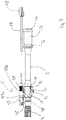
- Fig. 2 shows an enlarged detail Fig. 1 with the pipe 3 mounted on the gas take-off 5.
- the tube 3 comprises in its rear end a locking sleeve 23, on the underside of a locking and positioning pin 26 is provided and at the rear end to the gun shaft a pipe nut 24 is placed.
- the locking bushing 23 is inserted into a pipe receptacle, not shown here, and clamped over the pipe nut 24.
- the gas take-off 5 comprises a cylindrical tube bearing 27 for mounting on the weapon barrel 3.
- the muzzle fire damper 7 is removed or unscrewed and the gas removal 5 is postponed.
- a bore 29 passing through it is provided as a bearing for a transverse pin 30, which determines the gas take-off 5.
- Adjacent a bore 31 is provided as a bearing for a retaining bolt 32 for attachment of an attachment, eg. A 40mm HK grenade launcher.
- a gas adjusting device in the form of a gas adjusting bush 33 is mounted (cf. Fig. 13a, b and 15-21 ).
- a form spring 35 is used in bearings 37a, b at the gas take-off 5 (see also Fig. 14-21 ).
- the shape spring is used in conjunction with the bayonet lock for indexing and fixing the Gasverstellbuchse 33.
- gas cylinder 42 receives and determines there (see, inter alia Fig. 5 . 9 . 18 . 20 and 22 ).
- the short-stroke gas piston 43 penetrates the lid 39 and is surrounded at its outer end by a continuing fixed end cap 41 (see also Fig. 5 . 7 . 8th and 9-11 ).
- Fig. 2 is a gas piston rod or a throttle linkage 45 before firing on the end cap 41.
- the gas piston rod 45 is firmly connected to the closure support 47 of the closure assembly 19 (see also FIG Fig. 4a ).
- the propellant drives the short-stroke gas piston 43, so that this backwards in the direction of gun shaft 21 moves.
- the short-stroke gas piston 43 transmits the recorded pulse to the gas rod 45 and drives it with the associated bolt carrier 19 back towards the gun shaft 21st
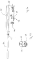
- Fig. 3 shows the gas piston rod 45 and the closure support 47 after firing in its rearmost position. Lid 41 and gas piston rod 45 are separated from each other. As a result, the short-stroke gas piston essentially differs from other gas pistons, which are coupled or connected to the gas piston rod or the closure carrier and together with the latter after firing, run back in the direction of the weapon shaft 21.
- Fig. 4 shows a detailed view of the closure assembly 19.
- the closure support 47 is coupled in its front end to the gas piston rod 45. On its underside, it comprises a locking head 49 which can be moved longitudinally and rotatably in its interior.
- the latter comprises a control bolt 51 guided in a control slot 53 for locking and unlocking in a known manner.
- Fig. 5 shows a partial exploded view of the gas take-off 5 Fig. 1 to 3 ,
- the gas piston or short-stroke gas piston 43 is removed from the gas cylinder 42 and decoupled from the cover 39 and the end cap 41.
- a locking section 57 extending approximately perpendicularly to the longitudinal direction is provided in the section surrounding the gas cylinder 42 for locking the cover or closing element 39.
- the lid 39 has for this purpose a counter-locking portion in its interior (see. Fig. 7 ).
- the two locking portions define the lid 39 in the manner of a bayonet lock on the gas take-off 5.
- the extending toward weapon shank 21 edges of the gas take-off 5 are chamfered for easier placement of the lid 39.
- the short-stroke gas piston 43 comprises at its front, mouth-side end a gas piston nose or valve pin 59 for longitudinally movable guidance and sealing in a gas passage 105 which extends in extension of the gas cylinder 42 to the mouth.
- the valve pin 59 is tapered at its front end for easy insertion into the gas outlet 105.
- the short-stroke gas piston 43 widens to the rear towards the shaft in a conical portion 61 and merges adjacent into a bearing portion 63 with a circumferential annular groove 65 on.
- the outer dimensions of the bearing portion 63 are approximately complementary to the inner dimensions of the gas cylinder 42.
- a sealant 67 in particular in the form of three sealing rings used to seal the short-stroke gas piston 43 relative to the gas cylinder 42.
- the sealing rings 67 also have a cleaning effect, since they expel dirt on the gas cylinder 42 to the front.
- the bearing portion 63 continues in the direction of shank stepped in a tapered cylindrical portion 69 which is provided at its rear end in a bearing portion 71 for mounting the short-stroke gas piston 43 at or with the end cap 41.
- the bearing portion 71 includes a threaded portion 40 (see. Fig. 18 ) which can be screwed with a mating thread (not shown) inside the end cap 41.
- a locking pin 94 is provided, which secures the end cap 41 in position (see. Fig. 18 . 20 and 22 ).
- the end cap 41 includes semicircular recesses 79 on its underside.
- the short-stroke gas piston 43 is first inserted into the gas cylinder and the lid or closing element 39 is placed thereon and locked via the locking section 57.
- the lid 39 comprises on its outer periphery a substantially circumferential sawtooth profile 75, which improves the grip of the lid 39, in particular with gloves or under adverse conditions.
- the cover 39 At its front end facing the pipe mouth, the cover 39 comprises a partially forwardly extending extension 73 (cf. Fig. 7 . 11 and 12 . 15 ).
- the lid 39 has an approximately U-shaped profile (see. Fig. 7 ).
- a pin 115 serves to position the gas take-off 5 on the weapon barrel 3.
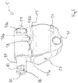
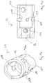
- Fig. 6 shows a perspective view of the gas take-off 5, in which the bearing portions 37 a and b are shown enlarged.
- the bearing portion 37a adjoins a bore 38 which penetrates the gas take-off 5 transversely.
- the bore 38 is used for locking / deductions 135a, b of the form spring.
- the bearings 37a, b are used for the use of the shaped spring 35.
- a cylindrical receiving portion 84 is provided for the gas adjusting bush 33.
- a gas outlet 86 from the gas cylinder 42 is provided inside the receiving portion 84.
- An insertion portion of a bayonet catchment gate 80 is for receiving a complementary pin 117 (see. Fig. 13a and b) is provided and merges into an annular bayonet link section 82, which serves to fix the gas adjusting bushing 33 on the gas take-off 5 via the pin 117.
- the shape spring 35 is used in conjunction with this bayonet closure for indexing and fixing the Gasverstellbuchse 33rd
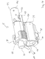
- Fig. 7 shows a detailed view of the cover or closure element 39 with its inner passage 81 for the short-stroke gas piston 43.
- the passage 81 widens conically to its edge, thus forming a conical insertion portion 91 for the passage of the short-stroke gas piston 43rd
- the passage 81 has at its peripheral edge semicircular bores or passages 83a and b, which serve for the removal of dirt particles and dirt. This measure ensures full function of the gas sampling 5 even under adverse circumstances.
- the cover 39 comprises in its U-profile two extending in the direction of the mouth extensions which have in their interior a locking portion 87 a, b for engagement with the locking portion 57 at the gas take-off 5.
- two attachment sections or insertion sections 85a and b are provided, which can be placed on the locking lugs 58a, b in the locking section 57 (cf. Fig. 12 ) and after putting them in their locking position are rotated (see. Fig. 11).
- Fig. 11 shows the lid 39 in its attachment position and Fig. 10 in its locking position. Adhere to the insertion portions 85a, b, the locking portions 87a, b, which engage around the locking lugs 58a, b as a bayonet closure and thus set the lid 39 on the gas take-off 5.
- an extension 73 is formed which serves with an indexing of the shaped spring provided in its outer side (cf. Fig. 11 . 12 and 15 ).
- Fig. 8 shows a side view of the mounted on the gun barrel 3 5 and gas Fig. 9 shows a longitudinal sectional view.
- a pipe inner wall or barrel bore 97 run known trains and fields to impart a spin to a projectile.
- a bearing portion 113 is provided for receiving and fixing the muzzle flash damper 7, for example. Via a threaded portion (not shown).
- the gas take-off 5 extends obliquely to the longitudinal direction of a tube bore 99 through which propellant gases are discharged into the gas take-off 5 after firing and passing a projectile.
- a gas bore or gas channel 101 sealingly adjoining the tube bore 99 is provided which likewise runs obliquely to the longitudinal direction and opens at its upper side in the gas cylinder 42 approximately in the region of the conical section 61 of the short-stroke gas piston 43.
- Fig. 9 is the short-stroke gas piston 43 in its rest position before a firing.
- the valve pin 59 is located within the gas passage 105 and seals it from the front to the mouth.
- the valve pin 59 is used for gas pressure regulation and ventilation of excess propellant gases in the direction of the mouth, which releases the gas cylinder 42 after a certain return path of the gas piston 43, whereupon the gas cylinder 42 is ventilated and no further substantial acceleration of the gas piston takes place more and the excess propellant gases over a gas passage with the inserted carbide bush 111 can escape with predetermined small diameter forward towards the mouth.
- the sealing rings 67 are provided within the groove 65 and the bearing portion 63 is stepped at its shaft-side end in the cylindrical portion 69 on.
- the step forms an abutment surface 103, which abuts against the abutment stop surface 89 in the closing element or cover 39 after firing to limit the movement of the short-stroke gas piston 43.
- the gas channel 105 merges at its front side toward the mouth into a stepped extension into a gas channel 107, which comprises a lateral gas outlet bore 109.
- a gas channel 107 which comprises a lateral gas outlet bore 109.
- Towards the mouth of the gas channel 107 passes into an insert 111 with an outlet nozzle to vent excess propellant gases to the outside.
- the insert 111 is as a carbide nozzle intended. This carbide bushing is resistant to erosion and serves as a nozzle for controlled discharge of propellant charge gases.
- Fig. 10 shows the lid 39 on the gas take-off 5 in the locked state.
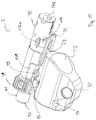
- Fig. 11 shows the unlocked obliquely mounted cover 39. In this position, the lid 39 can be removed to the rear towards the shaft.
- the short-stroke gas piston 43 is in Fig. 12 almost completely removed from the gas cylinder 42 and the cylindrical valve nose 59 to recognize. Further, the paired oppositely disposed locking lugs 58a and b of the locking portion 57 are shown.
- Fig. 13a shows a perspective view of the Gasverstellbuchse 33 and Fig. 13b a longitudinal sectional view.
- penetrating pin 117 is inserted, which is mounted from above in a bore.
- a half-round transverse to the longitudinal direction recess 119 is provided, which at their ends in each case Indexier einen for a detent 137 on the Shaped spring 35 has.
- the shaped spring 35 engages with a latching 120a, b in a form-fitting manner.
- Gasverstellbuchse 33 At the bottom of Gasverstellbuchse 33 is a gas adjusting bushing 33 passing through hole 121 is provided approximately at the height of the pin 117.
- a further bore 123 is provided and adjacent thereto a further slightly larger bore 125, which serves as a gas outlet opening for gas adjustment of the gas adjustment sleeve 35.
- the inner bore of the cylindrical Gasverstellbuchse 33 is complementary to the receiving portion 84 (see. Fig. 6 ) is tapered towards the front and passes into a step portion 127, which serves as a gas outlet for excess propellant gases.
- Fig. 14 shows the shape of spring 35, which at its front mouth-side end oblique insertion portions 131 a, b, which facilitate assembly of the form of spring 35 to the gas take-off 5 comprises. Stops 133a, b and 135a and b serve as stop and latching positions that lock the form spring 35 to the gas take-off 5. At the rear of the weapon shaft 21 facing the end of the form of spring 35, a detent 137 is provided, the indexing of Gasverstellbuchse 33 in the latches 120 a, b of the recess 119 at the Gasverstellbuchse 33 is used.
- a latching lug 139 which extends forwards in the longitudinal direction parallel to the U-shaped leg of the form spring 35 and at its front another latching lug 141 has.
- the latching lug 139 extends approximately at right angles parallel to the gas take-off 5 and the latching lug 141 indexes on the extension 73 of the cover 39 (see also FIG Fig. 15 and 16 ).
- the gas take 5 a bore 147 is shown.
- the Gasverstellbuchse 33 has at its mouth-side front to a transverse slot 145 and is used to adjust and medium tool.
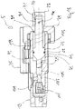
- Fig. 17 shows the gas take-off 5 with the Gasverstellbuchse 33 in the position "N" (normal operation) and Fig. 18 a corresponding longitudinal section in a view from above.
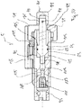
- Fig. 19 shows the Gasverstellbuchse 33 in its position "S" (muffler mode) and Fig. 20 an associated longitudinal section in a view from above.
- the latching lug 137 of the shaped spring 35 slides along the latching recess 119 from the latching position 120a to the latching position 120b.
- the pin 117 slides within the locking cam 82.
- the two positions "N” and “S” differ essentially in that the gas passage or gas passage opening 109 in Fig. 18 is closed at its upper side or outer side via the side wall of the locking bushing 33 and in Fig. 20 is aligned with the bore or gas outlet opening 125 in the Gasverstellbuchse 133 so that ventilated or ventilating propellant gases are discharged both via this side gas outlet than via the front valve nozzle in the insert 111 to ensure the weapon function when using a muffler (not shown) and Koch- or malfunction of the muffler to prevent. Since the carbide insert of the outlet nozzle has a passage with a defined small cross-section, brings the lateral gas outlet with a discharge and thus faster ventilation with it, which is open only in the silencer position.
- Fig. 21 shows a side view of the gas take-off 5 with extended short-stroke gas piston 43.
- the shaft-side end with the end cap 47 is located in Fig. 21 and 22 each on the left side, so mirrored to the previous figures.
- the annular abutment surface 103 of the short-stroke gas piston 43 bears against the abutment stop surface 89 in the closing element or cover 39.
- the gas piston rod 45 is already separated from the short-stroke gas piston 43 in this position.
- the gas piston rod 45 of the closure support 47 engages the cover or the end cap 41 and drives the short-stroke gas piston 43 back into its starting position. The cycle then begins again on firing.
Landscapes
- Engineering & Computer Science (AREA)
- General Engineering & Computer Science (AREA)
- Filling Or Discharging Of Gas Storage Vessels (AREA)
- Toys (AREA)
- Portable Nailing Machines And Staplers (AREA)
Abstract
Description
- Die vorliegende Erfindung betrifft eine Gasabnahme gemäß dem Oberbegriff des Anspruchs 1.
- Die Erfindung betrifft auch ein mit einer derartigen Gasabnahme ausgestattetes Waffenrohr sowie eine Selbstladefeuerwaffe mit einer derartigen Gasabnahme.
- In diesen Unterlagen betreffen Lagebezeichnungen, wie "oben", "unten", "vorne", "hinten", etc. stets eine in normaler Schusshaltung gehaltene Selbstladefeuerwaffe/Waffe, bei der die Seelenachse horizontal verläuft und die Schussabgabe nach vorne vom Schützen weg erfolgt.
- Gasabnahmen für Selbstladefeuerwaffen und damit ausgestattete Waffenrohre sowie Selbstladefeuerwaffen, beispielsweise Sturmgewehre, sind in unterschiedlichen Ausführungen bekannt.
- Gasabnahmen werden in der Regel in etwa im vorderen Drittel eines Laufs bzw. Waffenrohrs am Waffenrohr montiert. Dabei wird ein Gaskanal innerhalb der Gasabnahme in Fluidverbindung mit einer Bohrung im Waffenrohr gebracht, um bei Schussabgabe freiwerdende Treibgase zum Betrieb eines Gasdrucknachlademechanismus aus dem Waffenrohr abzuzweigen. Das Waffenrohr ist im Inneren eines Waffengehäuses in einer sogenannten Rohraufhahme aufgenommen und festgelegt. Ferner ist im Waffengehäuse eine längsbeweglich geführte Verschlussanordnung zur Schussabgabe, dem Ausziehen einer abgeschossenen Patronenhülse sowie zum Nachladen vorgesehen.
- Der Funktionsablauf beim Schießen und automatischen Nachladen lässt sich vereinfacht wie folgt darstellen: Zur Schussabgabe führt die Verschlussanordnung, insbesondere deren Verschlusskopf, eine Patrone aus einer Patronenzuführvorrichtung in bekannter Weise in ein Patronenlager im Rohr ein. Bei Betätigung eines Abzugsmechanismus trifft ein Schlagbolzen auf den Patronenboden und zündet dort eine Treibladung, so dass ein Projektil aus der Patronenhülse durch das Rohr abgeschossen wird. Sowie das Projektil die Bohrung im Waffenrohr passiert, lassen sich die beim Abschussvorgang freiwerdende Treibgase in die Gasabnahme abzweigen.
- Die abgezweigten Treibgase werden genutzt, um die Verschlussanordnung in bekannter Weise in eine Rückwärtsbewegung zu versetzen. Dabei treiben die Treibgase über die Gasabnahme und ein damit gekoppeltes Gasgestänge die Verschlussanordnung mit hoher Geschwindigkeit nach hinten in Richtung Schaft. Am Verschlusskopf ist ein Auszieher vorgesehen, der eine Patronenhülse an deren Rand am Hülsenboden umgreift und diese bei Rücklaufbewegung der Verschlussanordnung aus dem Patronenlager zieht. Eine Ausstoßvorrichtung stößt dann die Patronenhülse über ein Patronenauswurffenster in bekannter Weise aus dem Waffengehäuse. Beim Vorlauf der Verschlussanordnung wird nun wieder eine Patrone dem Patronenlager zugeführt und der Zyklus wiederholt sich.
-
US 3,592,101 offenbart ein Gasdrucknachladesystem für eine Selbstladefeuerwaffe. Unterhalb eines Laufs ist eine Gasabnahme mit einem Gaszylinder, der an seinem mündungsseitigen Ende einen eingeschraubten Einsatz mit Gasdurchlass aufweist, vorgesehen. Im Gaszylinder ist ein mit einer Trägheitsmasse verbundener Gaskolben eingesetzt, der das schaftseitige Ende des Gaszylinders durchdringt. Ein Gasdurchlass-Verstellmechanismus ist nicht beschrieben und dargelegt. -
WO 2006/137874 A2 offenbart eine Selbstladefeuerwaffe mit einer Gasabnahme, in deren zum Schaftende hin offenen Gaszylinder ein sogenannter Kurzhub-Gaskolben eingesetzt, der nach Schussabgabe einen Impuls über ein federbelastetes Gasgestänge an einen Verschlussträger überträgt. Der Treibmittelgasdruck lässt sich über eine zylindrischen Verstelleinrichtung oder einen Schieber zwischen Rohrbohrung und Gaszylinder mit Kreuzbohrungen mit unterschiedlichem Querschnittdurchmesser regulieren. -
EP 0 802 388 B1 der Anmelderin offenbart eine gattungsgemäße Gasabnahme für eine Selbstladefeuerwaffe. Ein Kurzhub-Gaskolben ist in einen in Schaftrichtung offenen Gaszylinder eingesetzt. Außerhalb des Gaszylinders umfasst der Gaskolben an seinem schaftseitigen Ende einen Führungsansatz. Eine Gaskolbenstange - dort Schubstange genannt-, ist in einer Bohrung im an den Führungsansatz angrenzenden Aufnahmebereich eingesetzt. Der Gaskolben ist an seinem mündungsseitigen Ende mit einem Ventilzapfen versehen, um Treibgase über eine Düse zu entlüften. Eine Gasdruckverstellung ist nicht beschrieben. - Aufgabe der vorliegenden Erfindung ist es, eine alternative Gasabnahme sowie ein damit ausgestattetes Waffenrohr und eine Selbstladefeuerwaffe mit einer solchen Gasabnahme bereitzustellen.
- Diese Aufgabe wird jeweils durch die Gegenstände der unabhängigen Ansprüche 1, 13 und 15 gelöst.
- Die gattungsbildende Gasabnahme zeichnet sich gemäß Anspruch 1 dadurch aus, dass an das dem Waffenschaft zugewandten Ende des Gaszylinders ein Abschlusselement lösbar ankoppelbar ist, das einen Durchlass für den Gaskolben aufweist.
- Das gattungsbildende Waffenrohr des Anspruchs 13 zeichnet sich dadurch aus, dass es mit einer Gasabnahme gemäß einem der Ansprüche 1 bis 12 versehen ist.
- Die gattungsbildende Selbstladefeuerwaffe des Anspruchs 15 zeichnet sich dadurch aus, dass sie mit einer Gasabnahme gemäß einem der Ansprüche 1 bis 13 versehen ist.
- Die Gasabnahme kann für verschiedene Selbstladefeuerwaffen vorgesehen sein, bspw. für ein Maschinengewehr, Scharfschützengewehr oder ein Sturmgewehr. Die Gasabnahme ist ausgelegt, um eine Verschlussanordnung insbesondere über ein Gasgestänge anzutreiben.
- Der Montageabschnitt der Gasabnahme umfasst in seinem Inneren eine zylindrische Aussparung mit zum Waffenrohr komplementäre Abmessungen. Zur Montage wird die Gasabnahme auf das Waffenrohr aufgeschoben bzw. aufgesetzt und in ihrer Lagerposition mittels einer im Waffenrohr vorgesehenen Bohrung, die sich quer zu dessen Längsrichtung erstreckt, verstiftet. Bei dieser Ausgestaltung ist es vorteilhaft nicht erforderlich, dass die Gasabnahme am Waffenrohr verschweißt wird, so dass auch kein Verzug auftritt.
- Der Gaskanal zur Zuleitung der Treibgase aus dem Waffenrohr in die Gasabnahme kann sich senkrecht oder schräg zur Längsrichtung der Gasabnahme erstrecken. Wenn der Gaskanal sich schräg zur Längsrichtung erstreckt trifft der Gasstrahl direkt auf den Gaskolben und treibt diesen direkt an. Bei rechtwinkligen Gasstrahl muss sich im Gaszylinder zunächst der Gasdruck aufbauen.
- Der Gaskolben kann als Kurzhub-Gaskolben für ein sogenanntes indirektes Gasdruckladesystem vorgesehen sein, wie dies bei der gattungsgemäßen Gasabnahme der Fall ist. Ein Kurzhub-Gaskolben zeichnet sich durch einen kurzen Bewegungsweg aus, der ausreicht, um einen entsprechenden Antriebsimpuls auf das Gasgestänge bzw. die Verschlussanordnung zu übertragen. Der Kurzhub-Gaskolben ist nicht mit einem Gasgestänge der Verschlussanordnung fest verbunden. Das Abschlusselement begrenzt den Kolbenhub des Kurzhub-Gaskolbens.
- Das Abschlusselement kann als Deckel vorgesehen sein, der an dem rohrseitigen Ende des Gaszylinders aufsetzbar ist und so das innere Volumen des Gaszylinders begrenzt. Nach außen kann das Abschlusselement mit einer rutschhemmenden Oberfläche versehen sein, beispielsweise mit Greifrippen oder als Sägezahnprofil für eine bessere Griffigkeit, insbesondere bei Bedienung mit Handschuhen oder in feuchter oder schmutziger Umgebung.
- Aufgrund der lösbaren Kopplung des Abschlusselements ist es möglich, dieses werkzeuglos abzunehmen und den Gaskolben aus dem Gaszylinder beispielsweise zu Reinigungszwecken zu entnehmen. Ein Durchdringen des Durchlasses im Abschlusselement gewährleistet die längsverschiebliche Bewegung des Gaskolbens.
- Die Gasabnahme kann aus geeigneten Materialien, beispielsweise Metall und dessen Legierungen hergestellt sein. Insbesondere kann die Gasabnahme beispielsweise über ein Spritzguss- oder Gussverfahren hergestellt sein. Vorteilhaft ist die Gasabnahme durch Extrusion oder Strangpressen oder als MIM-Teil über ein Metallpulverspritzgussverfahren ausgebildet. Dabei ist in der Regel kaum eine Nachbearbeitung erforderlich und eine integrale und stabile Bauweise möglich. Dies führt zu einer Kostenreduktion bei deren Herstellung. Ebenso weisen MIM-Teile kaum Abmessungsschwankungen auf und reduzieren so den Aufwand bei einer etwaigen Nachbearbeitung.
- Die Gasabnahme kann werkzeuglos für den Betrieb mit einem Schalldämpfer verstellbar sein und kann mit einer Schnittstelle für 40 mm Anbaugranatwerfer, beispielsweise den Granatwerfer HK269, ausgestattet sein.
- Insgesamt wird eine Gasabnahme mit hoher Präzision und Maßgenauigkeit bei geringen Fertigungstoleranzen bereitgestellt. Dabei lassen sich auch beliebige Designanforderungen an die Gasabnahme verwirklichen.
- Die lösbare Ankoppelung des Abschlusselements kann über geeignete Befestigungsmittel, beispielsweise Gewinde-Verbindung oder ein Bajonettverbindung erfolgen. Der Gaskolben kann mit seinen Außenabmessungen ganz oder teilweise komplementär zum Innenumfang des Gaszylinders ausgebildet sein, um eine Abdichtung zu gewährleisten.
- Bevorzugt umfasst der Gaskolben wenigstens ein Gaskolbenlager mit einem Dichtmittel, das den Gaskolben gegenüber dem Gaszylinder abdichtet (Anspruch 2).
- Der Gaskolben bzw. Kurzhub-Gaskolben kann sich zur Bildung eines Gaskolbenlagers konisch aufweiten, so dass wenigstens ein Gaskolbenlagerabschnitt, der sich ganz oder teilweise über die Längsrichtung des Gaszylinders erstreckt, einen in etwa zum Innenumfang des Gaszylinders komplementären Abschnitt aufweist. Bei Einsetzen eines Dichtmittels in diesen Lagerabschnitt lässt sich der Kolben gegenüber dem Gaszylinder abdichten, so dass dessen Rücklauf nach Schussabgabe gewährleistet ist. Das Dichtmittel kann bspw. aus wenigstens einem oder mehreren Dichtringen vorgesehen sein, die in einer im Gaskolbenlager vorgesehenen ringförmigen Aussparung einsetzbar sind. Auch lassen sich alternative geeignete Dichtmittel verwenden.
- Vorzugsweise umfasst das Abschlusselement eine innere Anschlagsfläche für eine Gegenanschlagsfläche des Gaskolbenlagers, die zur Begrenzung von der Rücklaufbewegung des Gaskolbens in Richtung Schaft dient (Anspruch 3).
- Vorteilhaft definiert der Anschlag die Rücklaufstrecke des Gaskolbens wiederholgenau. Beim Anschlag am Abschlusselement trennt sich der Gaskolben vom Gasgestänge, so dass die Verschlussanordnung und das Gasgestänge separat zurücklaufen. Beim Vorlauf der Verschlussanordnung kommt das Gasgestänge wieder in Anlage mit dem Gaskolben und verbringt diesen in seine Ausgangsposition.
- Die innere Anschlagsfläche kann beispielsweise als umlaufende Anschlagsschulter, die insbesondere ringförmig ausgebildet ist, vorgesehen sein. Auch kann die innere Anschlagsfläche konisch zulaufende Einführungsflächen für den Gaskolben aufweisen.
- Die Gegenanschlagsfläche am Gaskolben ist komplementär zur Anschlagsfläche ausgebildet, etwa ringförmig oder konisch. Vorteilhaft stellt diese Maßnahme konstruktiv mit einfachen Mitteln eine wiederholgenaue Bewegbarkeit des Gaskolbens über eine definierte Strecke bereit.
- Bevorzugt ist am Abschlusselement der Gasabnahme im Bereich der Anschlagsfläche wenigstens eine Aussparung zum Ableiten von Verschmutzungen vorgesehen (Anspruch 4).
- Die eine oder mehrere Aussparungen können beispielsweise als Bohrungen im Durchlass für den Gaskolben bzw. dessen Schaft im Abschlusselement bzw. Deckel vorgesehen sein, und ermöglichen einen Austritt von Schmutzpartikeln. Die Aussparungen können beispielsweise bei Herstellung des Abschlusselements eingebracht werden oder aber nachträglich als Bohrungen oder Ausfräsungen.
- Diese Maßnahme stellt mit konstruktiv einfachen Mitteln die Funktionsweise der Gasabnahme auch unter widrigen Bedingungen, beispielsweise unter starken Verschmutzungen sicher.
- Die Befestigungseinrichtung kann mit geeigneten Mitteln, beispielsweise Gewindeverbindungen, verwirklicht sein.
- Bevorzugt ist die Befestigungseinrichtung als ein Verschlussabschnitt am Außenumfang des Gaszylinders, insbesondere an seinem dem Schaft zugewandten Ende, vorgesehen, und das Abschlusselement ist in seinem Inneren mit einem komplementären Verschlussabschnitt vorgesehen, wobei die beiden Verschlussabschnitte insbesondere als BajonettVerschlüsse ausgebildet sind (Anspruch 5).
- Die Ausgestaltung eines Verschlussabschnitts am Außenumfang des Gaszylinders, erleichtert ein Aufsetzen des Abschlusselements. Eine Ausgestaltung als Bajonett-Verschluss ermöglicht mit konstruktiv einfachen Mitteln eine wiederholgenaue lösbare Verbindung zwischen Abschlusselement und Gaszylinder.
- Der Gaskolben bzw. Kurzhub-Gaskolben kann mit seinem das Abschlusselement durchdringenden Ende mit dem Gasgestänge der Verschlussanordnung unmittelbar in Kontakt gelangen.
- Bevorzugt ist jedoch der Gaskolben über ein Befestigungsmittel an einem Lagerabschnitt mit einem Aufsatz verbindbar (Anspruch 6).
- Der Aufsatz kann bspw. als Kappe vorgesehen sein, die über ein Befestigungsmittel, etwa einen Gewindeabschnitt, am Gaskolben und einem Gegengewinde im Inneren der Kappe verbindbar ist. Auch sind andere geeignete Befestigungsarten möglich. Die Kappe gelangt in Kontakt mit dem Ende der Gasstange und treibt diese an, sodass die Kappe, etwa bei Verschleiß, einfach ausgewechselt werden kann.
- Bevorzugt ist die Verbindung zwischen Gaskolben und Aufsatz über ein Sicherungselement gesichert (Anspruch 7).
- Als Sicherungselement kann zusätzlich zur Gewindeverbindung ein Stift oder Draht oder ein anders geartete Sicherungsmittel vorgesehen sein, das die Abschlusskappe am Schaftende des Kurzhub-Gaskolbens sichert, bspw. über einen Einsatz des Sicherungsmittels in einer Bohrung.
- Das Abschlusselement bzw. der Deckel kann eine sich in Richtung der Laufmündung erstreckende Verlängerung aufweisen, die insbesondere zum Eingriff mit einem elastischen Element vorgesehen ist.
- Bevorzugt ist am mündungsseitigen Ende des Gaskolbens eine Gaskolbennase ausgebildet, die innerhalb eines zylindrischen, insbesondere mehrstufigen Gasdurchlasses in der Gasabnahme wenigstens teilweise längsverschieblich lagerbar ist (Anspruch 8).
- Der Außendurchmesser des Gaskolbenschaftes kann sich in Richtung Rohrmündung verjüngen, sodass die Gaskolbennase in etwa komplementäre Außenabmessungen zum Innendurchmesser an der Gasabnahme vorgesehenen rohrförmigen Gasdurchlasses aufweist.
- Bevorzugt endet der Gasdurchlass in einer Gasauslassdüse, durch die Treibgase in Richtung Mündung nach außen ableitbar sind (Anspruch 9).
- Das Zusammenspiel zwischen Gaskolbennase und Gasdurchlass sowie Auslassdüse ermöglicht eine Ventilation überschüssiger Treibgase. Sowie der Gaskolben nach Schussabgabe sich so weit in Richtung Schaft bewegt hat, dass zwischen Gaskolbennase und komplementären Gasdurchlass am Gaszylinder Treibgase in den Gasdurchlass eindringen können, werden diese über die Auslassdüse nach vorne in Richtung Rohr ausgelassen. Die Auslassdüse kann insbesondere als Hartmetall-Einsatz in die Gasabnahme eingesetzt sein. Diese Maßnahme ermöglicht eine lange Lebensdauer der Gasdüse.
- Zusätzlich zur Fluidverbindung zwischen Gasdurchlass und Auslassdüse, kann im Bereich zwischen Gasdurchlass und Auslassdüse eine Gasauslassöffnung in einen zusätzlichen Gaskanal vorgesehen sein. Diese Maßnahme ermöglicht mit konstruktiv einfachen Mitteln eine Gasverstellung, wobei überschüssige Treibgase in eine oder mehrere Gasauslassöffnungen umgeleitet bzw. abgeleitet werden.
- Vorzugsweise ist am mündungsseitigen Ende der Gasabnahme eine Gasverstelleinrichtung vorgesehen, die einen mündungseitigen Abschnitt der Gasabnahme umgibt und zur Gasabgabe wenigstens in Fluidverbindung mit der Gasauslassdüse bringbar ist (Anspruch 10).
- Die Gasverstelleinrichtung kann bspw. als aufsetzbare Gasverstellbuchse vorgesehen sein, die einen insbesondere zylindrischen Außenabschnitt der Gasabnahme in Richtung des Waffenrohres umgreift. Eine zylindrische Ausgestaltung dieses Außenabschnitts ermöglicht eine einfache Verstellung der Gasverstellbuchse durch Rotation.
- Vorzugsweise ist die Gasverstellvorrichtung über eine Befestigungsvorrichtung mit der Gasabnahme koppelbar, insbesondere über einen Bajonett-Verschluss (Anspruch 11).
- Diese Maßnahme ermöglicht mit konstruktiv einfachen Mitteln ein wiederholgenaus Aufsetzen der Gasverstellvorrichtung sowie eine sichere Festlegung an der Gasabnahme sowie eine formschlüssige Verriegelung. Zusätzlich ermöglicht der Bajonett-Verschluss eine Verstellung der Gasverstellvorrichtung an der Gasabnahme.
- Der Bajonett-Verschluss kann eine Einführkulisse für einen Zapfen an der Gasverstellvorrichtung aufweisen, sodass beim Aufsetzen der Gasverstellbuchse der Zapfen in die Kulisse eingeführt wird. Bei Verdrehung kann der Zapfen in einen kreisförmig umlaufenden Bajonett-Verschlussabschnitt einfahren und ist dort gegen eine Längsbewegung gesichert.
- Bevorzugt umfasst die Gasverstellvorrichtung wenigstens eine Sicherungseinrichtung, über die sie zwischen wenigstens zwei Gasregelpositionen verstellbar und indexierbar ist (Anspruch 12).
- Zur Verstellung kann die Gasverstellvorrichtung insbesondere im oder gegen den Uhrzeigersinn verdrehbar sein. Die Sicherungseinrichtung kann beispielsweise als Rastposition oder Sicherungsstift vorgesehen sein, um eine unbeabsichtigte Verstellung aus der gewählten Gasregelposition zu verhindern.
- Bevorzugt ist die Sicherungseinrichtung als eine insbesondere u-förmige Formfeder vorgesehen, die in komplementären Aussparungen in der Gasabnahme einsetzbar und festlegbar ist (Anspruch 13).
- Die Formfeder wird auch als Rastfeder bezeichnet und ermöglicht eine elastische Indexierung der Gasverstellbuchse in jeweiligen Rastnuten. Die Formfeder kann insbesondere als U-förmiges Element vorgesehen sein, das einen Abschnitt der Gasabnahme umgreift. Dazu können Aussparungen im Inneren der Formfeder vorgesehen sein, die als Formfederverrastungen an komplementären Lagerabschnitten der Gasabnahme festgelegt bzw. festlegbar sind. Zusätzlich kann die Formfeder eine sich nach oben erstreckende Rastnase zur Indexierung der Gasverstellbuchse aufweisen.
- Die Formfeder kann an ihrem seitlichen Ende wenigstens eine sich in etwa in Längsrichtung erstrecken Verlängerung aufweisen, die über einen Verlängerungsabschnitt mit der Formfeder verbunden ist. An dem hinteren Ende der seitlichen Verlängerung kann eine Rastnase, insbesondere zackenförmige Rastnase, vorgesehen sein, die den Deckel bzw. das Abschlusselement indexiert und dazu mit einer Gegenausnehmung in einer Verlängerung des Abschlussabschnitts bzw. Deckels in Eingriff geht.
- Der Gaszylinder der Gasabnahme erstreckt sich koaxial zum Waffenrohr in dessen Längsrichtung.
- Bevorzugt umfasst die Selbstladefeuerwaffe ein Gasgestänge zur lösbaren Kopplung mit der Gasabnahme sowie eine mit dem Gasgestänge gekoppelte im Waffengehäuse längsbeweglich angeordnete Verschlussanordnung (Anspruch 16).
- Diese Maßnahme stellt mit konstruktiv einfachen Mitteln eine sichere Funktionsweise des Gasdrucknachlademechanismus sicher.
- Ausführungsbeispiele der Erfindung sind im Folgenden unter Bezugnahme auf die beigefügten schematischen Zeichen näher erläutert. Darin zeigen:
- Fig. 1
- eine Explosionsdarstellung einer erfindungsgemäßen Selbstladefeuerwaffe in einer Seitenansicht;
- Fig. 2
- eine an einem Waffenrohr montierte Gasabnahme mit Teilen einer Verschlussanordnung in einer Seitenansicht;
- Fig. 3
- die Gasabnahme aus
Fig. 2 nach Schussabgabe in einer Seitenansicht; - Fig. 4a
- die Verschlussanordnung aus
Fig. 2 und3 in einer Seitenansicht; - Fig. 4b
- die Verschlussanordnung aus
Fig. 4a von vorne; - Fig. 5
- eine Teil-Explosionsdarstellung der Gasabnahme aus
Fig. 1 bis 3 in einer Seitenansicht; - Fig. 6
- eine perspektivische Darstellung der Gasabnahme aus
Fig. 5 in einer Ansicht schräg von unten vorne; - Fig. 7
- eine perspektivische Darstellung des Abschlusselements/Deckels in einer Ansicht schräg von vorne oben;
- Fig. 8
- die Gasabnahme aus
Fig. 5 und6 auf dem Waffenrohr montiert in einer Seitenansicht; - Fig. 9
- eine Längsschnittdarstellung durch die Gasabnahme und das Waffenrohr aus
Fig. 8 ; - Fig. 10
- eine perspektivische Detaildarstellung der Gasabnahme aus
Fig. 1 bis 3 im verriegelten Zustand in einer Ansicht schräg von hinten oben; - Fig. 11
- die Gasabnahme aus
Fig. 10 im entriegelten Zustand; - Fig. 12
- die Gasabnahme aus
Fig. 11 im entriegelten und teilweise demontierten Zustand; - Fig. 13a
- eine perspektivische Darstellung einer Gasverriegelungsbuchse in einer Ansicht schräg von vorne unten;
- Fig. 13b
- eine Längsschnittdarstellung durch die Gasverstellbuchse aus
Fig. 13a ; - Fig. 14
- eine perspektivische Darstellung einer Formfeder in einer Ansicht schräg von vorne oben;
- Fig. 15
- eine perspektivische Darstellung der in die Gasabnahme aus
Fig. 1 bis 3 eingesetzten Formfeder in einer Ansicht schräg von vorne unten; - Fig. 16
- eine perspektivische Darstellung der Gasabnahme aus
Fig. 15 in einer Ansicht schräg von unten; - Fig. 17
- die Gasabnahme aus
Fig. 1 bis 3 in der Stellung "N" der Gasverstellbuchse in einer Seitenansicht; - Fig. 18
- eine Längsschnittdarstellung durch die Gasabnahme aus
Fig. 17 in einer Ansicht von oben; - Fig. 19
- die Gasabnahme aus
Fig. 17 in der Stellung "S" in einer Seitenansicht; - Fig. 20
- eine Längsschnittdarstellung durch die Gasabnahme aus
Fig. 19 in einer Ansicht von oben; - Fig. 21
- eine Seitenansicht der rechten Seite der Gasabnahme aus
Fig. 17 und19 mit vollständig ausgefahrenem Kurzhub-Gaskolben; und - Fig. 22
- eine Längsschnittdarstellung durch die Gasabnahme auf
Fig. 21 . - Der Aufbau einer erfindungsgemäßen Selbstladefeuerwaffe 1 wird zunächst anhand der
Fig. 1 erläutert.Fig. 1 zeigt die Selbstladefeuerwaffe 1 in einer Explosionsdarstellung. - Die Selbstladefeuerwaffe ist im vorliegenden Fall als ein Sturmgewehr (HK433) ausgeführt und umfasst im Wesentlichen folgende Elemente: ein Waffenrohr 3 mit einer daran montierten Gasabnahme 5 und einem Mündungsfeuerdämpfer 7; ein Waffengehäuse 9, in das das Waffenrohr 3 einsetzbar ist; ein mit dem Waffengehäuse 9 koppelbarer Handschutz 11 sowie ein an das Waffengehäuse 9 montierbares Griffstück 13. Ferner sind eine Durchladeeinrichtung 17, eine Verschlussanordnung 19 sowie eine am Waffengehäuse 9 ankoppelbare Schulterstütze 21 vorgesehen.
- Die einzelnen Baugruppen bzw. Bestandteile sowie deren Funktion sind an sich bekannt. Im Übrigen wird für deren Funktionsweise auf die Patentanmeldung der gleichnamigen Anmelderin unter dem Titel "Waffengehäuse und damit ausgestattete SelbstladeFeuerwaffe sowie ein Verfahren zur Herstellung eines Waffengehäuses" mit heutigem Anmeldetag verwiesen.
-
Fig. 2 zeigt eine vergrößerte Detaildarstellung ausFig. 1 mit der am Rohr 3 montierten Gasabnahme 5. Das Rohr 3 umfasst in seinem hinteren Ende eine Verriegelungsbuchse 23, an deren Unterseite ein Verriegelungs- und Positionierzapfen 26 vorgesehen ist und an deren hinteren Ende zum Waffenschaft eine Rohrmutter 24 aufgesetzt ist. Die Verriegelungsbuchse 23 wird in eine hier nicht gezeigte Rohraufnahme eingesetzt und über die Rohrmutter 24 verspannt. Für Details verweisen wir auf die vorstehend genannte parallele Anmeldung der Anmelderin. - Die Gasabnahme 5 umfasst ein zylindrisches Rohrlager 27 zur Montage auf dem Waffenrohr 3. Dazu wird der Mündungsfeuerdämpfer 7 abgenommen bzw. abgeschraubt und die Gasabnahme 5 aufgeschoben. Zum Festlegen der Gasabnahme 5 ist eine diese quer durchsetzende Bohrung 29 als Lager für einen Querstift 30 vorgesehen, der die Gasabnahme 5 festlegt. In den perspektivischen Darstellungen der
Fig. 10 und11 ist das Lager 29 im Detail gezeigt. Angrenzend ist eine Bohrung 31 als Lager für einen Haltebolzen 32 zur Befestigung eines Anbaugeräts, bspw. eines 40mm HK-Granatwerfers vorgesehen. - An der Vorderseite der Gasabnahme 5 ist eine Gasverstellvorrichtung in Form einer Gasverstellbuchse 33 aufgesetzt (vgl. insbesondere
Fig. 13a, b und15-21 ). In etwa zwischen Montageabschnitt 25 und Gasverstellbuchse 33 erstreckt sich unterhalb der Gasverstellbuchse 33 eine Formfeder 35 nach hinten, die in Lager 37a, b an der Gasabnahme 5 einsetzbar ist (vgl. auchFig. 14-21 ). Die Formfeder dient im Zusammenwirken mit dem Bajonett-Verschluss zum Indexieren und Festlegen der Gasverstellbuchse 33. Nach hinten grenzt ein Abschlusselement oder Deckel 39 an die Gasabnahme 5 an, der einen hier nicht gezeigten Kurzhub-Gaskolben in einem inFig. 2 nicht gezeigten Gaszylinder 42 aufnimmt und dort festlegt (vgl. u.a.Fig. 5 ,9 ,18 ,20 und22 ). Der Kurzhub-Gaskolben 43 durchdringt den Deckel 39 und ist an seinem äußeren Ende von einer fort festgelegten Abschlusskappe 41 umgeben (vgl. hierzu auchFig. 5 ,7 ,8 und9-11 ). - In
Fig. 2 liegt eine Gaskolbenstange bzw. ein Gasgestänge 45 vor Schussabgabe an der Abschlusskappe 41 an. Die Gaskolbenstange 45 ist mit dem Verschlussträger 47 der Verschlussanordnung 19 fest verbunden (vgl. auchFig. 4a ). Nach Schussabgabe und Abzweigung der Treibgase nachdem ein Projektil die Rohrbohrung 99 passiert hat, treibt das Treibgas den Kurzhub-Gaskolben 43 an, sodass sich dieser nach hinten in Richtung Waffenschaft 21 bewegt. Der Kurzhub-Gaskolben 43 überträgt dabei den aufgenommenen Impuls auf die Gasstange 45 und treibt diese mit dem damit verbundenen Verschlussträger 19 nach hinten in Richtung Waffenschaft 21. -
Fig. 3 zeigt die Gaskolbenstange 45 sowie den Verschlussträger 47 nach Schussabgabe in deren hintersten Position. Deckel bzw. Abschlusskappe 41 und Gaskolbenstange 45 sind voneinander getrennt. Dadurch unterscheidet sich der Kurzhub-Gaskolben im Wesentlichen von anderen Gaskolben, die mit der Gaskolbenstange oder dem Verschlussträger gekoppelt bzw. verbunden sind und mit diesen nach Schussabgabe gemeinsam in Richtung Waffenschaft 21 zurücklaufen. -
Fig. 4 zeigt eine Detaildarstellung der Verschlussanordnung 19. Der Verschlussträger 47 ist in seinem vorderen Ende mit der Gaskolbenstange 45 gekoppelt. An seiner Unterseite umfasst er einen in seinem Inneren längsbeweglich und verdrehbar geführten Verschlusskopf 49. Dieser umfasst einen in einer Steuerkulisse 53 geführten Steuerbolzen 51 zur Ver- und Entriegelung in bekannter Art und Weise. -
Fig. 5 zeigt eine Teil-Explosionsdarstellung der Gasabnahme 5 ausFig. 1 bis 3 . Der Gaskolben bzw. Kurzhub-Gaskolben 43 ist aus dem Gaszylinder 42 entnommen und von dem Deckel 39 sowie der Abschlusskappe 41 entkoppelt. In etwa am hinteren Ende der Gasabnahme 5 ist in dem den Gaszylinder 42 umgebenden Abschnitt ein sich in etwa senkrecht zur Längsrichtung erstreckender Verriegelungsabschnitt 57 zur Verrieglung des Deckels bzw. Abschlusselements 39 vorgesehen. Der Deckel 39 weist hierzu einen Gegen-Verriegelungsabschnitt in seinem Inneren auf (vgl.Fig. 7 ). Die beiden Verriegelungsabschnitte legen den Deckel 39 nach Art eines Bajonett-Verschlusses an der Gasabnahme 5 fest. Die sich in Richtung Waffenschaft 21 erstreckenden Kanten der Gasabnahme 5 sind für ein leichteres Aufsetzen des Deckels 39 angefast. - Der Kurzhub-Gaskolben 43 umfasst an seinem vorderen, mündungsseitigen Ende eine Gaskolbennase oder Ventilzapfen 59 zur längsbeweglichen Führung und Abdichtung in einem Gasdurchlass 105, der sich in Verlängerung des Gaszylinders 42 zur Mündung erstreckt. Der Ventilzapfen 59 ist an seinem vorderen Ende für einen einfachen Einsatz in den Gasauslass 105 konisch abgeschrägt. Der Kurzhub-Gaskolben 43 weitet sich nach hinten in Richtung Schaft in einen konischen Abschnitt 61 auf und geht angrenzend in einen Lagerabschnitt 63 mit einer umlaufenden ringförmigen Nut 65 über. Die Außenabmessungen des Lagerabschnitts 63 sind in etwa komplementär zu den Innenabmessungen des Gaszylinders 42. In die Nut 65 ist ein Dichtmittel 67, insbesondere in Form von drei Dichtringen eingesetzt, um den Kurzhub-Gaskolben 43 gegenüber dem Gaszylinder 42 abzudichten. Bei einer Längsbewegung des Kurzhub-Gaskolbens 43 innerhalb des Gaszylinders 42 haben die Dichtringe 67 auch eine reinigende Wirkung, da sie Verschmutzungen am Gaszylinder 42 nach vorne austreiben.
- Der Lagerabschnitt 63 geht weiter in Richtung Schaft gestuft in einen verjüngten zylindrischen Abschnitt 69 über, der an seinem hinteren Ende in einen Lagerabschnitt 71 zur Montage des Kurzhub-Gaskolbens 43 an bzw. mit der Abschlusskappe 41 vorgesehen ist. Der Lagerabschnitt 71 umfasst dazu eine Gewindeabschnitt 40 (vgl.
Fig. 18 ) der mit einem Gegengewinde (nicht gezeigt) im Inneren der Abschlusskappe 41 verschraubt werden kann. Zusätzlich ist ein Sicherungsstift 94 vorgesehen, der die Abschlusskappe 41 in ihrer Position sichert (vgl.Fig. 18 ,20 und22 ). Die Abschlusskappe 41 umfasst an ihrer Unterseite halbkreisförmige Aussparungen 79. - Im montierten Zustand bzw. zur Montage wird der Kurzhub-Gaskolben 43 zunächst in den Gaszylinder eingesetzt und darauf der Deckel bzw. Abschlusselement 39 aufgesetzt und über den Verriegelungsabschnitt 57 verriegelt. Der Deckel 39 umfasst an seinem Außenumfang ein weitgehend umlaufendes Sägezahnprofil 75, das die Griffigkeit des Deckels 39, insbesondere mit Handschuhen oder unter widrigen Bedingungen, verbessert. An seinem vorderen, der Rohrmündung zugewandten Ende, umfasst der Deckel 39 eine sich teilweise nach vorne erstreckende Verlängerung 73 (vgl. insbesondere
Fig. 7 ,11 und12 ,15 ). Der Deckel 39 hat ein in etwa u-förmiges Profil (vgl.Fig. 7 ). Ein Zapfen 115 dient zur Positionierung der Gasabnahme 5 am Waffenrohr 3. -
Fig. 6 zeigt eine perspektivische Darstellung der Gasabnahme 5, bei der die Lagerabschnitte 37a und b vergrößert dargestellt sind. Der Lagerabschnitt 37a grenzt an eine Bohrung 38 an, die die Gasabnahme 5 quer durchdringt. Die Bohrung 38 dient der Verrastung/Abschläge 135a,b der Formfeder. - Die Lager 37a, b dienen dem Einsatz der Formfeder 35. Am vorderen Ende der Gasabnahme 5 zur Rohrmündung hin ist ein zylindrischer Aufnahmeabschnitt 84 für die Gasverstellbuchse 33 vorgesehen. Im inneren des Aufnahmeabschnitts 84 ist ein Gasauslass 86 vom Gaszylinder 42 vorgesehen. Ein Einführungsabschnitt einer Bajonett-Verschlusskulisse 80 ist zur Aufnahme eines komplementären Zapfens 117 (vgl.
Fig. 13a und b) vorgesehen und geht in einen ringförmig Bajonett-Kulissenabschnitt 82 über, der zur Festlegung der Gasverstellbuchse 33 an der Gasabnahme 5 über den Zapfen 117 dient. Die Formfeder 35 dient im Zusammenwirken mit diesem Bajonett-Verschluss zum Indexieren und Festlegen der Gasverstellbuchse 33. -
Fig. 7 zeigt eine Detail-Darstellung des Deckels bzw. Abschluss-Elements 39 mit seinem inneren Durchlass 81 für den Kurzhub-Gaskolben 43. Der Durchlass 81 weitet sich zu seinem Rand konisch auf und bildet so einen konischen Einführungsabschnitt 91 für den Durchlass des Kurzhub-Gaskolbens 43. Der Durchlass 81 weist an seinem Umfangsrand halbrunde Bohrungen bzw. Durchlässe 83a und b auf, die der Abfuhr von Dreckpartikeln und Verschmutzungen dienen. Diese Maßnahme gewährleistet eine volle Funktion der Gasabnahme 5 auch unter widrigen Umständen. - Der Deckel 39 umfasst in seinem U-Profil zwei sich in Richtung der Mündung erstreckende Verlängerungen, die in ihrem Inneren einen Verriegelungsabschnitt 87a,b zum Eingriff mit dem Verriegelungsabschnitt 57 an der Gasabnahme 5 aufweisen. Dazu sind zwei Aufsatzabschnitte bzw. Einführungsabschnitte 85a und b vorgesehen, die auf die Verriegelungswarzen 58a,b im Verriegelungsabschnitt 57 aufsetzbar sind (vgl.
Fig. 12 ) und nach dem Aufsetzen in ihre Verriegelungsposition verdreht werden (vgl.Fig. 11). Fig. 11 zeigt den Deckel 39 in seiner Aufsatzposition undFig. 10 in seiner Verriegelungsposition. An die Einführungsabschnitte 85a, b grenzen die Verriegelungsabschnitte 87a, b an, die als Bajonett-Verschluss die Verriegelungswarzen 58a,b umgreifen und so den Deckel 39 an der Gasabnahme 5 festlegen. - An dem oberen Verriegelungsabschnitt 87b in
Fig. 7 ist eine Verlängerung 73 ausgebildet, die mit einer, in Ihrer Außenseite vorgesehenen Rast einer Indexierung der Formfeder dient (vgl.Fig. 11 ,12 und15 ). -
Fig. 8 zeigt eine Seitenansicht der auf dem Waffenrohr 3 montierten Gasabnahme 5 undFig. 9 zeigt eine Längsschnittdarstellung. Innerhalb einer Rohrinnenwandung bzw. Lauf bohrung 97 verlaufen bekannten Züge und Felder, um einem Projektil einen Drall zu vermitteln. Am Mündungsabschnitt des Waffenrohres 3 ist ein Lagerabschnitt 113 zur Aufnahme und Festlegung des Mündungsfeuerdämpfers 7 vorgesehen, bspw. über einen Gewindeabschnitt (nicht gezeigt). An der der Gasabnahme 5 zugewandten Seite des Waffenrohres 3 erstreckt sich schräg zur in Längsrichtung eine Rohrbohrung 99, durch die nach Schussabgabe und Passieren eines Projektils Treibgase in die Gasabnahme 5 abgeleitet werden. In der Gasabnahme ist eine dichtend an die Rohrbohrung 99 anschließende Gasbohrung oder Gaskanal 101 vorgesehen, die bzw. der ebenso schräg zur Längsrichtung verläuft und an seiner Oberseite im Gaszylinder 42 in etwa im Bereich des konischen Abschnitts 61 des Kurzhub-Gaskolbens 43 mündet. - In
Fig. 9 befindet sich der Kurzhub-Gaskolben 43 in seiner Ruheposition vor einer Schussabgabe. Der Ventilzapfen 59 befindet sich innerhalb des Gasdurchlasses bzw. Gaskanals 105 und dichtet diesen nach vorn zur Mündung hin ab. Der Ventilzapfen 59 dient zur Gasdruckregulierung und zur Ventilierung überschüssiger Treibmittelgase in Richtung der Mündung, die den Gaszylinder 42 nach einem bestimmten Rücklaufweg des Gaskolbens 43 frei gibt, woraufhin der Gaszylinder 42 ventiliert wird und keine weitere wesentliche Beschleunigung des Gaskolbens mehr stattfindet und die überschüssigen Treibladungsgase über einen Gasdurchlass mit der eingesetzten Hartmetallbuchse 111 mit vorbestimmten kleinen Durchmesser nach vorn in Richtung Mündung entweichen können. - Die Dichtringe 67 sind innerhalb der Nut 65 vorgesehen und der Lagerabschnitt 63 geht an seinem schaftseitigen Ende gestuft in den zylindrischen Abschnitt 69 über. Die Stufe bildet eine Anschlagsfläche 103, die an der Gegenanschlagsfläche 89 im Abschlusselement bzw. Deckel 39 nach Schussabgabe zur Begrenzung der Bewegung des Kurzhub-Gaskolbens 43 anschlägt.
- Der Gaskanal 105 geht an seiner Vorderseite zur Mündung hin in eine gestufte Verlängerung in einen Gaskanal 107 über, der eine seitliche Gasauslassbohrung 109 umfasst. In Richtung Mündung geht der Gaskanal 107 in ein Einsatzstück 111 mit einer Auslassdüse über, um überschüssige Treibgase nach außen zu ventilieren. Der Einsatz 111 ist als Hartmetalldüse vorgesehen. Diese Hartmetallbuchse ist erosionsresistent und dient als Düse zum kontrollierten Ausfluss der Treibladungsgase.
-
Fig. 10 zeigt den Deckel 39 an der Gasabnahme 5 im verriegelten Zustand.Fig. 11 zeigt den entriegelten schräg aufgesetzten Deckel 39. In diese Stellung kann der Deckel 39 nach hinten in Richtung Schaft entnommen werden. Der Kurzhub-Gaskolben 43 ist inFig. 12 nahezu vollständig aus dem Gaszylinder 42 entnommen und die zylindrische Ventilnase 59 zu erkennen. Ferner sind die paarweise gegenüberliegend angeordneten Verriegelungswarzen 58a und b des Verriegelungsabschnitts 57 gezeigt. -
Fig. 13a zeigt eine perspektivische Ansicht der Gasverstellbuchse 33 undFig. 13b eine Längsschnittdarstellung. An der Oberseite ist ein die Gasverstellbuchse 33 durchdringender Zapfen 117 eingesetzt, der von oben in einer Bohrung montiert ist. Dieser Zapfen 117 dient zur Bajonett-Verriegelung der Gasverstellbuchse 33 an der zylindrischen Aufnahme 84 der Gasabnahme 5. An der unteren Außenseite der Gasverstellbuchse 33 ist eine halbrund quer zur Längsrichtung verlaufende Aussparung 119 vorgesehen, die an ihren Enden jeweils Indexierstellungen für einer Rastnase 137 an der Formfeder 35 aufweist. Die Formfeder 35 geht mit einer Verrastung 120a, b formschlüssig in Eingriff. - An der Unterseite der Gasverstellbuchse 33 ist in etwa in Höhe des Zapfens 117 eine die Gasverstellbuchse 33 durchsetzende Bohrung 121 vorgesehen. Darüber ist eine weitere Bohrung 123 vorgesehen und daran angrenzend eine weitere etwas größere Bohrung 125, die als Gasauslassöffnung zur Gasverstellung der Gasverstellbuchse 35 dient. Die Innenbohrung der zylindrischen Gasverstellbuchse 33 ist komplementär zum Aufnahmeabschnitt 84 (vgl.
Fig. 6 ) ausgebildet ist, verjüngt sich nach vorne hin konisch und geht in einen Stufenabschnitt 127 über, der als Gasauslass für überschüssigen Treibgasen dient. -
Fig. 14 zeigt die Formfeder 35, die an ihrem vorderen mündungsseitigen Ende schräg verlaufende Einführungsabschnitte 131a, b, die eine Montage der Formfeder 35 an der Gasabnahme 5 erleichtern, umfasst. Anschläge 133a, b und 135a und b dienen als Anschlags- und Rastpositionen, die die Formfeder 35 an der Gasabnahme 5 verrasten. Am hinteren dem Waffenschaft 21 zugewandten Ende der Formfeder 35 ist eine Rastnase 137 vorgesehen, die der Indexierung der Gasverstellbuchse 33 in den Verrastungen 120a, b der Ausnehmung 119 an der Gasverstellbuchse 33 dient. An der in Schussrichtung gesehen rechten Seite verlängert sich der Schenkel der U-förmigen Formfeder 35 nach außen oben und hinten in eine Rastfahne 139, die sich nach vorne in Längsrichtung parallel zum U-förmigen Schenkel der Formfeder 35 erstreckt und an ihrer Vorderseite eine weitere Rastnase 141 aufweist. Die Rastfahne 139 erstreckt sich in etwa rechtwinklig parallel zur Gasabnahme 5 und die Rastnase 141 indexiert an der Verlängerung 73 des Deckels 39 (vgl. auchFig. 15 und16 ). An der Unterseite inFig. 16 der Gasabnahme 5 ist eine Bohrung 147 gezeigt. Die Gasverstellbuchse 33 weist an ihrer mündungsseitigen Vorderseite einen quer verlaufenden Schlitz 145 auf und dient der Verstellung auch mittel Werkzeug. -
Fig. 17 zeigt die Gasabnahme 5 mit der Gasverstellbuchse 33 in der Position "N" (Normalbetrieb) undFig. 18 eine korrespondierende Längsschnittdarstellung in einer Ansicht von oben.Fig. 19 zeigt die Gasverstellbuchse 33 in deren Position "S" (Schalldämpferbetrieb) undFig. 20 eine zugehörige Längsschnitt-Darstellung in einer Ansicht von oben. Zur Verstellung der Gasverstellbuchse 33 wird diese entweder mit einem Werkzeug im Schlitz 145 oder händisch um etwa 90° zwischen den Positionen "N" und "S" verdreht. Dabei gleitet die Rastnase 137 der Formfeder 35 entlang der Rastausnehmung 119 von der Verrastungsposition 120a zur Verrastungsposition 120b. Zeitgleich gleitet der Zapfen 117 innerhalb der Verriegelungskulisse 82. - Die beiden Stellungen "N" und "S" unterscheiden sich im Wesentlichen dadurch, dass der Gasdurchlasskanal bzw. Gasdurchlassöffnung 109 in
Fig. 18 an ihrer Oberseite bzw. Außenseite über die Seitenwand der Verriegelungsbuchse 33 verschlossen ist und inFig. 20 mit der Bohrung bzw. Gasauslassöffnung 125 in der Gasverstellbuchse 133 fluchtet, sodass ventilierte oder ventilierende Treibgase sowohl über diesen seitlichen Gasauslass als über die vordere Ventildüse im Einsatz 111 abgelassen werden, um die Waffenfunktion bei Verwendung eines Schalldämpfers (nicht gezeigt) zu gewährleisten und Über- bzw. Fehlfunktionen des Schalldämpfers zu verhindern. Da der Hartmetall-Einsatz der Auslassdüse einen Durchlass mit einem definierten kleinen Querschnitt aufweist, bringt der seitliche Gasauslass eine Entlastung und damit schnellere Ventilation mit sich, die nur in der Schalldämpferstellung geöffnet ist. -
Fig. 21 zeigt eine Seitenansicht der Gasabnahme 5 mit ausgefahrenen Kurzhub-Gaskolben 43. Das schaftseitige Ende mit der Abschlusskappe 47 befindet sich inFig. 21 und22 jeweils auf der linken Seite, also spiegelverkehrt zu den vorausgegangenen Figuren. Die ringförmige Anschlagsfläche 103 des Kurzhub-Gaskolbens 43 liegt an der Gegenanschlagsfläche 89 im Abschlusselement bzw. Deckel 39 an. Die Gaskolbenstange 45 ist in dieser Position bereits vom Kurzhub-Gaskolben 43 getrennt. Beim Vorlauf der Verschlussanordnung 19 greift die Gaskolbenstange 45 des Verschlussträgers 47 am Deckel bzw. der Abschlusskappe 41 an und treibt den Kurzhub-Gaskolben 43 wieder in dessen Ausgangsposition. Der Zyklus beginnt dann bei Schussabgabe erneut. - Weitere Ausgestaltungen der Erfindung ergeben sich für den Fachmann aus den abhängen Ansprüchen und den nachfolgenden Zeichnungen.
Claims (16)
- Gasabnahme (5) für eine Selbstladefeuerwaffe (1), mit:einem Montageabschnitt (25) zur Befestigung der Gasabnahme (5) an einem Waffenrohr (3),einem Gaszylinder (42), der über einen Gaskanal (101) mit einer Rohrbohrung (99) im Waffenrohr (3) verbindbar ist,einem im Gaszylinder (42) längsverschieblich angeordneten Gaskolben (43) zum Antreiben eines Gasdrucknachlademechanismus,
dadurch gekennzeichnet, dassan das dem Waffenschaft zugewandten Ende des Gaszylinders (42) ein Abschlusselement (39) lösbar ankoppelbar ist, das einen Durchlass (81) für den Gaskolben (43) aufweist. - Gasabnahme (5) nach Anspruch 1, dadurch gekennzeichnet, dass der Gaskolben (43) ein Gaskolbenlager (63) mit einem Dichtmittel (67) umfasst, das den Gaskolben (43) gegenüber dem Gaszylinder (42) abdichtet.
- Gasabnahme (5) nach einem der vorstehenden Ansprüche, dadurch gekennzeichnet, dass das Abschlusselement (39) eine innere Anschlagsfläche (89) für eine Gegenanschlagsfläche (103) des Gaskolbenlagers (63) zur Begrenzung von der Rücklaufbewegung des Gaskolbens (43) in Richtung Schaft dient.
- Gasabnahme (5) nach einem der vorstehenden Ansprüche, dadurch gekennzeichnet, dass am Abschlusselement (39) im Bereich der Anschlagsfläche (89) wenigstens eine Aussparung (83a, b) zum Ableiten von Verschmutzungen vorgesehen ist.
- Gasabnahme (5) nach einem der vorstehenden Ansprüche, dadurch gekennzeichnet, dass die Befestigungseinrichtung (57, 58a,b) als ein Verschlussabschnitt am Außenumfang des Gaszylinders (42), insbesondere an seinem dem Schaft zugewandten Ende, vorgesehen ist, und das Abschlusselement (39) in seinem Inneren eine komplementären Verschlussabschnitt (85a,b, 87a,b) umfasst, wobei die Verschlussabschnitte (57, 58a,b; 85a,b, 87a,b) als Bajonettverschluss ausgebildet sind.
- Gasabnahme (5) nach einem der vorstehenden Ansprüche, dadurch gekennzeichnet, dass der Gaskolben (43) über ein Befestigungsmittel (40) an einem Lagerabschnitt (71) mit einem Aufsatz (41) verbindbar ist.
- Gasabnahme (5) nach Anspruch 5, dadurch gekennzeichnet, dass die Verbindung zwischen Gaskolben (43) und Aufsatz (41) über ein Sicherungselement (44) gesichert ist.
- Gasabnahme (5) nach einem der vorstehenden Ansprüche, gekennzeichnet durch eine Gaskolbennase (59) am mündungsseitigen Ende des Gaskolbens (43), die innerhalb eines zylindrischen, insbesondere mehrstufigen Gasdurchlasses (105, 107) in der Gasabnahme (5) wenigstens teilweise längsverschieblich lagerbar ist.
- Gasabnahme (5) nach Anspruch 8, dadurch gekennzeichnet, dass der Gasdurchlass (105, 107) in eine Gasauslassdüse (111) mündet, durch die Treibgase in Richtung Mündung nach Außen ableitbar sind.
- Gasabnahme (5) nach einem der vorstehenden Ansprüche, gekennzeichnet durch eine Gasverstelleinrichtung (33) am mündungsseitigen Ende der Gasabnahme (5), die einen mündungseitigen Abschnitt der Gasabnahme (5) umgibt und zur Gasabgabe wenigstens in Fluidverbindung mit der Gasauslassdüse (111) bringbar ist.
- Gasabnahme (5) nach Anspruch 10, dadurch gekennzeichnet, dass die Gasverstelleinrichtung (33) über eine Befestigungsvorrichtung (80, 82, 117) mit der Gasabnahme (5) lösbar koppelbar ist, insbesondere über einen Bajonettverschluss (80, 82, 117).
- Gasabnahme (5) nach einem der Ansprüche 10 oder 11, dadurch gekennzeichnet, dass die Gasverstelleinrichtung (33) über eine Sicherungseinrichtung (35, 119, 120a,b 137) zwischen wenigstens zwei Gasregelpositionen verstellbar und indexierbar ist.
- Gasabnahme (5) nach Anspruch 12, dadurch gekennzeichnet, dass die Sicherungseinrichtung (35, 119, 120a,b 137) als, insbesondere u-förmige, Formfeder (35) vorgesehen ist, die in komplementäre Lager (37) in der Gasabnahme (5) einsetzbar und festlegbar ist.
- Waffenrohr (3) mit einer Gasabnahme (5) nach einem der vorstehenden Ansprüche.
- Selbstladefeuerwaffe (1) mit einer Gasabnahme (5) nach einem der Ansprüche 1 bis 13.
- Selbstladefeuerwaffe (1) nach Anspruch 15, umfassend eine Gaskolbenstange (45) zur lösbaren Kopplung mit der Gasabnahme (5) sowie eine mit der Gaskolbenstange (45) gekoppelte, im Waffengehäuse (9) längsbeweglich angeordnete Verschlussanordnung (19).
Priority Applications (1)
| Application Number | Priority Date | Filing Date | Title |
|---|---|---|---|
| HRP20201920TT HRP20201920T1 (hr) | 2017-03-07 | 2020-12-01 | Reduktor plina i njime opremljena cijev oružja, kao i vatreno oružje s automatskim punjenjem s takvim reduktorom plina |
Applications Claiming Priority (1)
| Application Number | Priority Date | Filing Date | Title |
|---|---|---|---|
| DE102017002165.1A DE102017002165B4 (de) | 2017-03-07 | 2017-03-07 | Gasabnahme und damit ausgestattetes Waffenrohr sowie Selbstladefeuerwaffe mit einer solchen Gasabnahme |
Publications (3)
| Publication Number | Publication Date |
|---|---|
| EP3372944A2 true EP3372944A2 (de) | 2018-09-12 |
| EP3372944A3 EP3372944A3 (de) | 2018-12-19 |
| EP3372944B1 EP3372944B1 (de) | 2020-09-02 |
Family
ID=61598957
Family Applications (1)
| Application Number | Title | Priority Date | Filing Date |
|---|---|---|---|
| EP18160522.1A Active EP3372944B1 (de) | 2017-03-07 | 2018-03-07 | Gasabnahme und damit ausgestattetes waffenrohr sowie selbstladefeuerwaffe mit einer solchen gasabnahme |
Country Status (4)
| Country | Link |
|---|---|
| US (1) | US10830546B2 (de) |
| EP (1) | EP3372944B1 (de) |
| DE (1) | DE102017002165B4 (de) |
| HR (1) | HRP20201920T1 (de) |
Families Citing this family (8)
| Publication number | Priority date | Publication date | Assignee | Title |
|---|---|---|---|---|
| DE102017002165B4 (de) * | 2017-03-07 | 2018-12-27 | Heckler & Koch Gmbh | Gasabnahme und damit ausgestattetes Waffenrohr sowie Selbstladefeuerwaffe mit einer solchen Gasabnahme |
| US20190360772A1 (en) * | 2018-05-25 | 2019-11-28 | KBA Custom, LLC | Adjustable gas block |
| HRP20221357T1 (hr) | 2019-10-04 | 2022-12-23 | Glock Technology Gmbh | Karabin na plinski pogon |
| US11994357B2 (en) * | 2020-01-06 | 2024-05-28 | Axts, Inc. | Timing, fastening, and sealing features for firearm gas blocks |
| US11187473B1 (en) | 2021-02-01 | 2021-11-30 | A. W. Richey | Firearm |
| US11313633B1 (en) | 2021-04-13 | 2022-04-26 | A. W. Richey | Firearm |
| DE102021005162B4 (de) | 2021-10-15 | 2025-08-28 | Heckler & Koch Gmbh | Gasabnahme |
| US12259208B2 (en) * | 2022-01-14 | 2025-03-25 | KNS Precision, Inc. | Adjustable gas valve for firearm |
Family Cites Families (22)
| Publication number | Priority date | Publication date | Assignee | Title |
|---|---|---|---|---|
| GB574607A (en) | 1943-07-14 | 1946-01-14 | William Warren Triggs | Improvements relating to gas-operated self-loading firearms |
| CH250094A (de) | 1946-04-02 | 1947-08-15 | Zbrojovka Brno As | Gasdrucklader, dessen Gaszylinder durch einen lösbaren Stöpsel abgeschlossen ist. |
| US2582989A (en) * | 1948-05-06 | 1952-01-22 | Earle M Harvey | Gas piston for firearms |
| US3592101A (en) | 1969-04-21 | 1971-07-13 | Olin Corp | Gas system for autoloading firearm |
| US4503632A (en) * | 1983-08-12 | 1985-03-12 | Cuevas James W | Recoil reducing mechanism for shotguns |
| DE19615181C2 (de) * | 1996-04-17 | 2001-02-01 | Heckler & Koch Gmbh | Gasdruckladendes Selbstladegewehr |
| MX2007003286A (es) | 2004-09-17 | 2007-10-16 | Colt Defense Llc | Arma de fuego que tiene un sistema de operacion de gas. |
| EP1998135B1 (de) * | 2006-02-09 | 2013-04-24 | Colt Defense LLC | Vorderschaft für ein Gewehr |
| ITMI20061022A1 (it) * | 2006-05-24 | 2007-11-25 | Remington Arms Co Inc | Arma da fuoco azionata mediante gas |
| DE102006056130A1 (de) | 2006-08-03 | 2008-02-07 | Heckler & Koch Gmbh | Gasabnahmeanordnung und Lauf bzw. Waffe mit einer Gasabnahmeanordnung |
| US8210089B2 (en) * | 2008-07-01 | 2012-07-03 | Adcor Industries, Inc. | Firearm having an indirect gas impingement system |
| SG193880A1 (en) * | 2008-09-12 | 2013-10-30 | Colt Defense Llc | Firearm having a hybrid indirect gas operating system |
| US8689672B2 (en) * | 2009-10-23 | 2014-04-08 | Charles Blue Cassels | Anti-wear buffer device for bolt carrier assembly |
| US8869674B2 (en) | 2012-02-14 | 2014-10-28 | Michael Alan Ruck | Gas piston control system for a firearm |
| US8893608B2 (en) * | 2012-07-03 | 2014-11-25 | Lawrence S. Kramer | Gas piston system for M16/AR15 rifle or M4 carbine systems |
| US8863639B2 (en) | 2012-08-23 | 2014-10-21 | Lwrc International Llc | Adjustable gas block for a gas operated firearm |
| US9719739B2 (en) | 2014-02-06 | 2017-08-01 | Bernard (Bernie) T. Windauer | Gas block balancing piston for auto-loading firearm |
| DE202015001384U1 (de) | 2015-02-20 | 2015-03-23 | Waffen-Albert Gmbh | Handfeuerwaffe mit Gaskolbeneinrichtung |
| US9273916B1 (en) * | 2015-01-05 | 2016-03-01 | Carmelo Russo | Firearm impingement system having adjustable gas block |
| US9766027B1 (en) * | 2016-06-06 | 2017-09-19 | Lawrence J. Cavanaugh | Indirect impingement operating system for a firearm |
| US9816769B1 (en) * | 2016-10-25 | 2017-11-14 | Ambimjb, Llc | Gas piston firearm system and method |
| DE102017002165B4 (de) * | 2017-03-07 | 2018-12-27 | Heckler & Koch Gmbh | Gasabnahme und damit ausgestattetes Waffenrohr sowie Selbstladefeuerwaffe mit einer solchen Gasabnahme |
-
2017
- 2017-03-07 DE DE102017002165.1A patent/DE102017002165B4/de active Active
-
2018
- 2018-03-07 US US15/914,904 patent/US10830546B2/en active Active
- 2018-03-07 EP EP18160522.1A patent/EP3372944B1/de active Active
-
2020
- 2020-12-01 HR HRP20201920TT patent/HRP20201920T1/hr unknown
Also Published As
| Publication number | Publication date |
|---|---|
| DE102017002165A1 (de) | 2018-09-13 |
| US20180259278A1 (en) | 2018-09-13 |
| US10830546B2 (en) | 2020-11-10 |
| DE102017002165B4 (de) | 2018-12-27 |
| HRP20201920T1 (hr) | 2021-01-22 |
| EP3372944A3 (de) | 2018-12-19 |
| EP3372944B1 (de) | 2020-09-02 |
Similar Documents
| Publication | Publication Date | Title |
|---|---|---|
| DE102017002165B4 (de) | Gasabnahme und damit ausgestattetes Waffenrohr sowie Selbstladefeuerwaffe mit einer solchen Gasabnahme | |
| EP3372943B1 (de) | Waffengehäuse und damit ausgestattete selbstlade-feuerwaffe sowie ein verfahren zur herstellung eines waffengehäuses | |
| EP1963772B1 (de) | Gasabnahmeanordnung und lauf bzw. waffe mit einer gasabnahmeanordnung | |
| DE202012011647U1 (de) | Komponententräger für eine Feuerwaffe | |
| EP2018508B1 (de) | WAFFENVERSCHLUßSYSTEM | |
| DE102006056130A1 (de) | Gasabnahmeanordnung und Lauf bzw. Waffe mit einer Gasabnahmeanordnung | |
| EP3372942B1 (de) | Verriegelbare selbstlade-handfeuerwaffe | |
| EP1596151A1 (de) | Repetierwaffe | |
| EP3677867A2 (de) | Durchladevorrichtung einer selbstladefeuerwaffe sowie mit einer durchladevorrichtung ausgestattete selbstladefeuerwaffe | |
| DE102014109567A1 (de) | Gasdruckladegewehr | |
| WO2007014770A1 (de) | Schnellfeuerwehr und umrüstverfahren | |
| EP1953491B1 (de) | Schusswaffe | |
| AT393028B (de) | Gasentnahmesystem fuer eine feuerwaffe | |
| DE102021005162B4 (de) | Gasabnahme | |
| EP2363678B1 (de) | Repetiergewehr mit austauschbarer Lauf-Verschlussgruppe | |
| DE2647899A1 (de) | Gasdruckbetaetigte schusswaffe | |
| EP3096107A2 (de) | Verschluss für ein gewehr | |
| DE1161789B (de) | Granatenwerfvorrichtung, die am Lauf von tragbaren Feuerwaffen anbringbar ist, die mit Gasableitung versehen sind, welche auch als Muendungsbremse wirkt | |
| WO2013010775A1 (de) | Gasabnahmeanordnung für einen lauf einer waffe | |
| DE10051708B4 (de) | Selbstladepistole | |
| DE102020106078B3 (de) | Gasdruckladegewehr | |
| DE202014103141U1 (de) | Gasdruckladegewehr | |
| DE3919761C2 (de) | Geschütz für flüssige Treibladungen | |
| EP1052470A2 (de) | Aufsatzvorrichtung für die Gasabnahme einer automatischen Waffe | |
| DE102004029204A1 (de) | Handfeuerwaffe |
Legal Events
| Date | Code | Title | Description |
|---|---|---|---|
| PUAI | Public reference made under article 153(3) epc to a published international application that has entered the european phase |
Free format text: ORIGINAL CODE: 0009012 |
|
| STAA | Information on the status of an ep patent application or granted ep patent |
Free format text: STATUS: THE APPLICATION HAS BEEN PUBLISHED |
|
| AK | Designated contracting states |
Kind code of ref document: A2 Designated state(s): AL AT BE BG CH CY CZ DE DK EE ES FI FR GB GR HR HU IE IS IT LI LT LU LV MC MK MT NL NO PL PT RO RS SE SI SK SM TR |
|
| AX | Request for extension of the european patent |
Extension state: BA ME |
|
| PUAL | Search report despatched |
Free format text: ORIGINAL CODE: 0009013 |
|
| AK | Designated contracting states |
Kind code of ref document: A3 Designated state(s): AL AT BE BG CH CY CZ DE DK EE ES FI FR GB GR HR HU IE IS IT LI LT LU LV MC MK MT NL NO PL PT RO RS SE SI SK SM TR |
|
| AX | Request for extension of the european patent |
Extension state: BA ME |
|
| RIC1 | Information provided on ipc code assigned before grant |
Ipc: F41A 5/28 20060101ALI20181109BHEP Ipc: F41A 5/26 20060101AFI20181109BHEP |
|
| STAA | Information on the status of an ep patent application or granted ep patent |
Free format text: STATUS: REQUEST FOR EXAMINATION WAS MADE |
|
| 17P | Request for examination filed |
Effective date: 20190619 |
|
| RBV | Designated contracting states (corrected) |
Designated state(s): AL AT BE BG CH CY CZ DE DK EE ES FI FR GB GR HR HU IE IS IT LI LT LU LV MC MK MT NL NO PL PT RO RS SE SI SK SM TR |
|
| GRAP | Despatch of communication of intention to grant a patent |
Free format text: ORIGINAL CODE: EPIDOSNIGR1 |
|
| STAA | Information on the status of an ep patent application or granted ep patent |
Free format text: STATUS: GRANT OF PATENT IS INTENDED |
|
| INTG | Intention to grant announced |
Effective date: 20200417 |
|
| GRAS | Grant fee paid |
Free format text: ORIGINAL CODE: EPIDOSNIGR3 |
|
| GRAA | (expected) grant |
Free format text: ORIGINAL CODE: 0009210 |
|
| STAA | Information on the status of an ep patent application or granted ep patent |
Free format text: STATUS: THE PATENT HAS BEEN GRANTED |
|
| AK | Designated contracting states |
Kind code of ref document: B1 Designated state(s): AL AT BE BG CH CY CZ DE DK EE ES FI FR GB GR HR HU IE IS IT LI LT LU LV MC MK MT NL NO PL PT RO RS SE SI SK SM TR |
|
| REG | Reference to a national code |
Ref country code: GB Ref legal event code: FG4D Free format text: NOT ENGLISH |
|
| REG | Reference to a national code |
Ref country code: AT Ref legal event code: REF Ref document number: 1309336 Country of ref document: AT Kind code of ref document: T Effective date: 20200915 Ref country code: CH Ref legal event code: EP |
|
| REG | Reference to a national code |
Ref country code: DE Ref legal event code: R096 Ref document number: 502018002310 Country of ref document: DE |
|
| REG | Reference to a national code |
Ref country code: IE Ref legal event code: FG4D Free format text: LANGUAGE OF EP DOCUMENT: GERMAN |
|
| REG | Reference to a national code |
Ref country code: CH Ref legal event code: NV Representative=s name: E. BLUM AND CO. AG PATENT- UND MARKENANWAELTE , CH |
|
| REG | Reference to a national code |
Ref country code: HR Ref legal event code: TUEP Ref document number: P20201920T Country of ref document: HR |
|
| REG | Reference to a national code |
Ref country code: HR Ref legal event code: T1PR Ref document number: P20201920 Country of ref document: HR |
|
| REG | Reference to a national code |
Ref country code: LT Ref legal event code: MG4D |
|
| PG25 | Lapsed in a contracting state [announced via postgrant information from national office to epo] |
Ref country code: FI Free format text: LAPSE BECAUSE OF FAILURE TO SUBMIT A TRANSLATION OF THE DESCRIPTION OR TO PAY THE FEE WITHIN THE PRESCRIBED TIME-LIMIT Effective date: 20200902 Ref country code: SE Free format text: LAPSE BECAUSE OF FAILURE TO SUBMIT A TRANSLATION OF THE DESCRIPTION OR TO PAY THE FEE WITHIN THE PRESCRIBED TIME-LIMIT Effective date: 20200902 Ref country code: NO Free format text: LAPSE BECAUSE OF FAILURE TO SUBMIT A TRANSLATION OF THE DESCRIPTION OR TO PAY THE FEE WITHIN THE PRESCRIBED TIME-LIMIT Effective date: 20201202 Ref country code: BG Free format text: LAPSE BECAUSE OF FAILURE TO SUBMIT A TRANSLATION OF THE DESCRIPTION OR TO PAY THE FEE WITHIN THE PRESCRIBED TIME-LIMIT Effective date: 20201202 Ref country code: LT Free format text: LAPSE BECAUSE OF FAILURE TO SUBMIT A TRANSLATION OF THE DESCRIPTION OR TO PAY THE FEE WITHIN THE PRESCRIBED TIME-LIMIT Effective date: 20200902 Ref country code: GR Free format text: LAPSE BECAUSE OF FAILURE TO SUBMIT A TRANSLATION OF THE DESCRIPTION OR TO PAY THE FEE WITHIN THE PRESCRIBED TIME-LIMIT Effective date: 20201203 |
|
| REG | Reference to a national code |
Ref country code: NL Ref legal event code: MP Effective date: 20200902 |
|
| PG25 | Lapsed in a contracting state [announced via postgrant information from national office to epo] |
Ref country code: PL Free format text: LAPSE BECAUSE OF FAILURE TO SUBMIT A TRANSLATION OF THE DESCRIPTION OR TO PAY THE FEE WITHIN THE PRESCRIBED TIME-LIMIT Effective date: 20200902 Ref country code: RS Free format text: LAPSE BECAUSE OF FAILURE TO SUBMIT A TRANSLATION OF THE DESCRIPTION OR TO PAY THE FEE WITHIN THE PRESCRIBED TIME-LIMIT Effective date: 20200902 Ref country code: LV Free format text: LAPSE BECAUSE OF FAILURE TO SUBMIT A TRANSLATION OF THE DESCRIPTION OR TO PAY THE FEE WITHIN THE PRESCRIBED TIME-LIMIT Effective date: 20200902 |
|
| REG | Reference to a national code |
Ref country code: HR Ref legal event code: ODRP Ref document number: P20201920 Country of ref document: HR Payment date: 20210225 Year of fee payment: 4 |
|
| PG25 | Lapsed in a contracting state [announced via postgrant information from national office to epo] |
Ref country code: PT Free format text: LAPSE BECAUSE OF FAILURE TO SUBMIT A TRANSLATION OF THE DESCRIPTION OR TO PAY THE FEE WITHIN THE PRESCRIBED TIME-LIMIT Effective date: 20210104 Ref country code: RO Free format text: LAPSE BECAUSE OF FAILURE TO SUBMIT A TRANSLATION OF THE DESCRIPTION OR TO PAY THE FEE WITHIN THE PRESCRIBED TIME-LIMIT Effective date: 20200902 Ref country code: EE Free format text: LAPSE BECAUSE OF FAILURE TO SUBMIT A TRANSLATION OF THE DESCRIPTION OR TO PAY THE FEE WITHIN THE PRESCRIBED TIME-LIMIT Effective date: 20200902 Ref country code: SM Free format text: LAPSE BECAUSE OF FAILURE TO SUBMIT A TRANSLATION OF THE DESCRIPTION OR TO PAY THE FEE WITHIN THE PRESCRIBED TIME-LIMIT Effective date: 20200902 |
|
| PG25 | Lapsed in a contracting state [announced via postgrant information from national office to epo] |
Ref country code: ES Free format text: LAPSE BECAUSE OF FAILURE TO SUBMIT A TRANSLATION OF THE DESCRIPTION OR TO PAY THE FEE WITHIN THE PRESCRIBED TIME-LIMIT Effective date: 20200902 Ref country code: AL Free format text: LAPSE BECAUSE OF FAILURE TO SUBMIT A TRANSLATION OF THE DESCRIPTION OR TO PAY THE FEE WITHIN THE PRESCRIBED TIME-LIMIT Effective date: 20200902 Ref country code: IS Free format text: LAPSE BECAUSE OF FAILURE TO SUBMIT A TRANSLATION OF THE DESCRIPTION OR TO PAY THE FEE WITHIN THE PRESCRIBED TIME-LIMIT Effective date: 20210102 |
|
| REG | Reference to a national code |
Ref country code: DE Ref legal event code: R097 Ref document number: 502018002310 Country of ref document: DE |
|
| PG25 | Lapsed in a contracting state [announced via postgrant information from national office to epo] |
Ref country code: SK Free format text: LAPSE BECAUSE OF FAILURE TO SUBMIT A TRANSLATION OF THE DESCRIPTION OR TO PAY THE FEE WITHIN THE PRESCRIBED TIME-LIMIT Effective date: 20200902 |
|
| PLBE | No opposition filed within time limit |
Free format text: ORIGINAL CODE: 0009261 |
|
| STAA | Information on the status of an ep patent application or granted ep patent |
Free format text: STATUS: NO OPPOSITION FILED WITHIN TIME LIMIT |
|
| 26N | No opposition filed |
Effective date: 20210603 |
|
| PG25 | Lapsed in a contracting state [announced via postgrant information from national office to epo] |
Ref country code: SI Free format text: LAPSE BECAUSE OF FAILURE TO SUBMIT A TRANSLATION OF THE DESCRIPTION OR TO PAY THE FEE WITHIN THE PRESCRIBED TIME-LIMIT Effective date: 20200902 Ref country code: DK Free format text: LAPSE BECAUSE OF FAILURE TO SUBMIT A TRANSLATION OF THE DESCRIPTION OR TO PAY THE FEE WITHIN THE PRESCRIBED TIME-LIMIT Effective date: 20200902 |
|
| PG25 | Lapsed in a contracting state [announced via postgrant information from national office to epo] |
Ref country code: MC Free format text: LAPSE BECAUSE OF FAILURE TO SUBMIT A TRANSLATION OF THE DESCRIPTION OR TO PAY THE FEE WITHIN THE PRESCRIBED TIME-LIMIT Effective date: 20200902 |
|
| PG25 | Lapsed in a contracting state [announced via postgrant information from national office to epo] |
Ref country code: IE Free format text: LAPSE BECAUSE OF NON-PAYMENT OF DUE FEES Effective date: 20210307 Ref country code: LU Free format text: LAPSE BECAUSE OF NON-PAYMENT OF DUE FEES Effective date: 20210307 |
|
| REG | Reference to a national code |
Ref country code: HR Ref legal event code: ODRP Ref document number: P20201920 Country of ref document: HR Payment date: 20220225 Year of fee payment: 5 |
|
| REG | Reference to a national code |
Ref country code: HR Ref legal event code: ODRP Ref document number: P20201920 Country of ref document: HR Payment date: 20230228 Year of fee payment: 6 |
|
| PG25 | Lapsed in a contracting state [announced via postgrant information from national office to epo] |
Ref country code: NL Free format text: LAPSE BECAUSE OF NON-PAYMENT OF DUE FEES Effective date: 20200923 Ref country code: CY Free format text: LAPSE BECAUSE OF FAILURE TO SUBMIT A TRANSLATION OF THE DESCRIPTION OR TO PAY THE FEE WITHIN THE PRESCRIBED TIME-LIMIT Effective date: 20200902 |
|
| P01 | Opt-out of the competence of the unified patent court (upc) registered |
Effective date: 20230526 |
|
| PG25 | Lapsed in a contracting state [announced via postgrant information from national office to epo] |
Ref country code: HU Free format text: LAPSE BECAUSE OF FAILURE TO SUBMIT A TRANSLATION OF THE DESCRIPTION OR TO PAY THE FEE WITHIN THE PRESCRIBED TIME-LIMIT; INVALID AB INITIO Effective date: 20180307 |
|
| REG | Reference to a national code |
Ref country code: HR Ref legal event code: ODRP Ref document number: P20201920 Country of ref document: HR Payment date: 20240227 Year of fee payment: 7 |
|
| PG25 | Lapsed in a contracting state [announced via postgrant information from national office to epo] |
Ref country code: MK Free format text: LAPSE BECAUSE OF FAILURE TO SUBMIT A TRANSLATION OF THE DESCRIPTION OR TO PAY THE FEE WITHIN THE PRESCRIBED TIME-LIMIT Effective date: 20200902 |
|
| PG25 | Lapsed in a contracting state [announced via postgrant information from national office to epo] |
Ref country code: MT Free format text: LAPSE BECAUSE OF FAILURE TO SUBMIT A TRANSLATION OF THE DESCRIPTION OR TO PAY THE FEE WITHIN THE PRESCRIBED TIME-LIMIT Effective date: 20200902 |
|
| REG | Reference to a national code |
Ref country code: HR Ref legal event code: ODRP Ref document number: P20201920 Country of ref document: HR Payment date: 20250226 Year of fee payment: 8 |
|
| PGFP | Annual fee paid to national office [announced via postgrant information from national office to epo] |
Ref country code: IT Payment date: 20250331 Year of fee payment: 8 |
|
| PGFP | Annual fee paid to national office [announced via postgrant information from national office to epo] |
Ref country code: CH Payment date: 20250401 Year of fee payment: 8 |
|
| PG25 | Lapsed in a contracting state [announced via postgrant information from national office to epo] |
Ref country code: TR Free format text: LAPSE BECAUSE OF FAILURE TO SUBMIT A TRANSLATION OF THE DESCRIPTION OR TO PAY THE FEE WITHIN THE PRESCRIBED TIME-LIMIT Effective date: 20200902 |
|
| REG | Reference to a national code |
Ref country code: HR Ref legal event code: ODRP Ref document number: P20201920 Country of ref document: HR Payment date: 20260225 Year of fee payment: 9 |
|
| REG | Reference to a national code |
Ref country code: CH Ref legal event code: U11 Free format text: ST27 STATUS EVENT CODE: U-0-0-U10-U11 (AS PROVIDED BY THE NATIONAL OFFICE) Effective date: 20260401 |
|
| PGFP | Annual fee paid to national office [announced via postgrant information from national office to epo] |
Ref country code: GB Payment date: 20260324 Year of fee payment: 9 |
|
| PGFP | Annual fee paid to national office [announced via postgrant information from national office to epo] |
Ref country code: DE Payment date: 20260320 Year of fee payment: 9 |
|
| PGFP | Annual fee paid to national office [announced via postgrant information from national office to epo] |
Ref country code: HR Payment date: 20260225 Year of fee payment: 9 Ref country code: AT Payment date: 20260319 Year of fee payment: 9 |
|
| PGFP | Annual fee paid to national office [announced via postgrant information from national office to epo] |
Ref country code: BE Payment date: 20260323 Year of fee payment: 9 |
|
| PGFP | Annual fee paid to national office [announced via postgrant information from national office to epo] |
Ref country code: FR Payment date: 20260324 Year of fee payment: 9 |
|
| PGFP | Annual fee paid to national office [announced via postgrant information from national office to epo] |
Ref country code: CZ Payment date: 20260224 Year of fee payment: 9 |