EP3372738B1 - Rosette mit verringerter klapperneigung für unterputz installierte sanitärarmaturen - Google Patents
Rosette mit verringerter klapperneigung für unterputz installierte sanitärarmaturen Download PDFInfo
- Publication number
- EP3372738B1 EP3372738B1 EP18160889.4A EP18160889A EP3372738B1 EP 3372738 B1 EP3372738 B1 EP 3372738B1 EP 18160889 A EP18160889 A EP 18160889A EP 3372738 B1 EP3372738 B1 EP 3372738B1
- Authority
- EP
- European Patent Office
- Prior art keywords
- wall
- geometry
- covering system
- cover
- mounting geometry
- Prior art date
- Legal status (The legal status is an assumption and is not a legal conclusion. Google has not performed a legal analysis and makes no representation as to the accuracy of the status listed.)
- Active
Links
Images

Classifications
-
- E—FIXED CONSTRUCTIONS
- E03—WATER SUPPLY; SEWERAGE
- E03C—DOMESTIC PLUMBING INSTALLATIONS FOR FRESH WATER OR WASTE WATER; SINKS
- E03C1/00—Domestic plumbing installations for fresh water or waste water; Sinks
- E03C1/02—Plumbing installations for fresh water
-
- E—FIXED CONSTRUCTIONS
- E03—WATER SUPPLY; SEWERAGE
- E03B—INSTALLATIONS OR METHODS FOR OBTAINING, COLLECTING, OR DISTRIBUTING WATER
- E03B7/00—Water main or service pipe systems
- E03B7/04—Domestic or like local pipe systems
-
- E—FIXED CONSTRUCTIONS
- E03—WATER SUPPLY; SEWERAGE
- E03B—INSTALLATIONS OR METHODS FOR OBTAINING, COLLECTING, OR DISTRIBUTING WATER
- E03B7/00—Water main or service pipe systems
- E03B7/09—Component parts or accessories
- E03B7/095—Component holders or housings, e.g. boundary boxes
-
- E—FIXED CONSTRUCTIONS
- E03—WATER SUPPLY; SEWERAGE
- E03C—DOMESTIC PLUMBING INSTALLATIONS FOR FRESH WATER OR WASTE WATER; SINKS
- E03C1/00—Domestic plumbing installations for fresh water or waste water; Sinks
- E03C1/02—Plumbing installations for fresh water
- E03C1/04—Water-basin installations specially adapted to wash-basins or baths
- E03C1/042—Arrangements on taps for wash-basins or baths for connecting to the wall
-
- E—FIXED CONSTRUCTIONS
- E03—WATER SUPPLY; SEWERAGE
- E03C—DOMESTIC PLUMBING INSTALLATIONS FOR FRESH WATER OR WASTE WATER; SINKS
- E03C2201/00—Details, devices or methods not otherwise provided for
- E03C2201/50—Constructional features of escutcheons for domestic plumbing installations
Definitions
- the DE 10 2015 009 105 A1 finally shows another type of connection between a cover and a carrier plate, with an elastic securing band being used from the outside in order to stabilize a form-fitting connection.
- the present invention is generally based on the object of contributing to the elimination of one or more disadvantages resulting from the prior art.
- an object of the invention is to provide cladding systems with a lower noise development during operation, which are also well suited for installation and maintenance of the control elements without the need for a special use of tools.
- a cladding system according to an embodiment 1 as described in claim 1 contributes to the solution of at least one of the above objects.
- the first fastening geometry surrounds the cover by at least 50%, preferably at least 70% and particularly preferably at least 90%. It is also preferred that the elastic fastening geometry surrounds the cover by at least 50%, preferably at least 70% and particularly preferably at least 90%. Furthermore, it is preferred that the elastic fastening element is part of a seal. Preferably, the elastic fastening element is formed in one piece with the seal.
- the cladding system is configured according to embodiment 1, with the elastic attachment geometry having a lip.
- the lip touches the wall in the case of the built-in trim system.
- the lid touches the lip in the case of the built-in trim system.
- the lip is preferably designed to avoid direct contact between the lid and the wall in the case of the built-in distribution system.
- the lip is substantially triangular, with the base of the triangle forming part of the attachment geometry and the two legs of this triangle touching the wall and cover in the case of the built-in distribution system.
- the lip preferably runs around at least 50%, preferably at least 70% and particularly preferably at least 90% of the circumference of the fastening geometry. In this way it can be achieved that the lip avoids direct contact between the wall and the ceiling in as many areas as possible between the cover and the wall in the case of the built-in cladding system.
- the cladding system is designed according to embodiment 1 or 2, with the elastic attachment geometry having a snap-in geometry designed and configured for snapping into the first attachment geometry.
- the snap geometry is preferably designed as a bead. This bead is preferably located farther from the wall in the case of the built-in cladding system compared to the lip. Furthermore, it is preferred that when the cover is placed on the carrier plate, part of the snap geometry, in particular the bead, is pressed in and, when the cover is moved further towards the wall, relaxed.
- the elastic fastening geometry is formed from an elastomer. If the elastic attachment geometry is part of a seal, this is preferably also formed from an elastomer. Particularly suitable elastomers are those that allow reversible indentation by manual force. In this way, the cover can be placed and connected in a form-fitting manner on the snap-on geometry of the elastic fastening geometry without the use of special tools. Furthermore, the selection of such elastomers also allows the cover to be released by hand without the use of special tools.
- elastomers which, after being irreversibly indented, last for a period of time in a range of 1-20 seconds, preferably in a range of 1-5 seconds and more preferably in a range of 1-3 seconds It takes seconds until they have reached the starting position again before being irreversibly pressed in.
- Particularly preferred elastomers are thermoplastic elastomers.
- the elastomer can be in the form of a foam. It is preferred here that the surface of these foams is sealed.
- the elastic fastening geometry is preferably formed in one piece and is therefore also preferably formed essentially completely from the elastomer.
- the paneling system is designed according to one of the preceding embodiments, with the elastomer being selected from the group consisting of rubber, polyisoprene, polybutadiene, polyurethane and polysilane or a combination of at least two of these.
- the elastomer according to the invention consists of a mixture of at least two of the aforementioned elastomers.
- the elastomer according to the invention consists of a copolymer.
- such copolymers are formed from two or more monomers selected from the group consisting of ethylene, propylene, butadiene and isoprene. In this context, particular mention should be made of ethylene-propylene-diene rubber.
- the cladding system is designed in such a way that the first fastening geometry is more rigid than the elastic fastening geometry.
- the lid is preferably formed from a material such as metal or hard plastic.
- the first attachment geometry is formed from a material such as metal or hard plastic. According to the invention, this material is so strong that it is suitable for indenting the elastomer discussed above without being indented or otherwise deformed in the process.
- Typical metals in this context are steel, in particular sheet steel, or aluminum.
- Preferred plastics here are polystyrene, acrylonitrile-butadiene-styrene copolymer, polypropylene, polyamide, polycarbonate and other thermoplastics.
- the cladding system is designed according to one of the preceding embodiments, with the first fastening geometry having a recess or a bulge or both, each set up and designed to receive the elastic fastening geometry in a form-fitting manner.
- the curvature is formed in such a way that when the cover with the first fastening geometry is pushed onto the elastic fastening geometry, the curvature presses in the elastomer. If a recess is provided in the first fastening geometry, this is preferably located closer to the wall in comparison to the bulge. The recess allows the previously compressed elastomer to relax. The first fastening geometry is thus fixed in its position by the elastic fastening geometry.
- a first fastening geometry which is preferably designed like a hook in cross section, hooks into this after the bead of the elastic fastening geometry has been pressed in and slides over it, in that the bead relaxes in the recess of the first fastening geometry.
- the cladding system is designed according to one of the preceding embodiments, wherein the part of the cover that faces the wall in the case of wall mounting of the cladding system is separated from the wall by at least one separating part of the elastic fastening geometry located between the wall and the cover .
- the trend part is preferably designed in the form of a lip. The statements made above in connection with the lip apply here in the same way.
- the carrier plate has a seal that at least partially surrounds the carrier plate.
- the seal is preferably formed from an elastomer. Therefore, in this context, the above statements also apply here.
- the seal is mounted in the area of the backing plate which, in the case of hole mounting, will be received therein.
- the gasket seals the backing plate against this wall of the hole. Also in connection with the seal, it is preferred that this covers at least 50%, preferably 50%, of the area of the carrier plate accommodated through the wall opening at least 70% and more preferably at least 90%.
- the trim system is configured according to any of the preceding embodiments, wherein the seal has a sealing surface having a groove.
- This configuration of the surface supports positive or frictional anchoring of the carrier plate in the wall opening.
- the grooves on the sealing surface are formed by circumferential rings.
- the trim system is configured according to any of the previous embodiments, including additionally a control.
- the control is preferably designed as a mixer or valve.
- Another preferred type of control is a utility meter.
- two or more controls are included in the trim system of the present invention.
- the control element or controls can be provided as flush-mounted units in a safe and visually appealing manner.
- the cladding system is designed according to one of the preceding embodiments, wherein the cladding system is provided in a wall.
- the walls are preferably located in sanitary rooms or household rooms.
- Preferred sanitary rooms are bathrooms and toilets.
- Preferred household rooms are kitchens, utility rooms or laundry rooms.
- the wall with the hole is provided on construction sites of buildings, in particular during their construction or conversion.
- a line system is usually concealed behind the wall, which in particular carries water, preferably hot water and cold water, gas or other utilities of a building.
- the providers of supply carried out in this line system are regulated via control elements, preferably valves or mixers. Essential parts of these controls are behind the wall or in the hole.
- This hole now needs to be closed, with the cladding system according to the invention closing the hole, preferably by covering or inserting it or both.
- the closure preferably takes place in such a way that the hole is no longer visible.
- the closing it is preferable that the hole is closed in a moisture-proof and dust-proof manner.
- an embodiment 11 as a use of the cladding system according to any one of the 1st to 9th embodiments for cladding flush-mounted facilities in walls lined with grouted tiles, which is advantageous for reducing noise.
- the noises that come into consideration are those that arise when the cover is touched while the control elements are being handled. This includes, in particular, rattling noises that occur, for example, when an operator hits the lid. Such rattling noises occur in particular on wall surfaces with tiles and especially when there are gaps between the tiles.
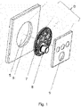
- FIG 1 shows a schematic representation of a cladding system 0 according to the invention.
- the cladding system 0 according to the invention was used to cover a hole 5 in a wall 1 .
- the carrier plate 3 is set up and designed in such a way that it terminates with the walls 6 of the hole 5 or covers it with its larger area.
- the support plate has one or more recesses 7 in which the control elements 8 can be accommodated.
- the carrier plate 3 has a seal with an elastic fastening geometry 4 .
- the seal 4 runs around the edge of the support plate 3 .
- the cladding system 0 also has a cover 2 .
- the cover 2 is set up and designed in such a way that it at least covers the surface of the carrier plate 3 .
- the cover 2 has one or more further cutouts 9 which, like the cutout 7 , are suitable for receiving a plurality of control elements 8 .
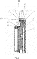
- FIG 2 shows a schematic cross-sectional illustration of a cladding system 0 according to the invention.
- the cover 2 has a cover wall 10 surrounding the cover 2 with an inner surface 11 . Parts of the inner surface 11 press on a surface 12 of the elastic fastening geometry 4.2 on the carrier plate 3 to form a form-fitting connection.
- the elastic fastening geometry 4.2 has a lip 4.1. This lip 4.1 is provided between an edge 2.2 of the top wall 10 and the wall 1. The lip 4.1 should be a Bumping the edge 2.2. to the wall 1 complicate.
- the carrier plate 3 has a seal 4.3.
- the seal 4.3 begins further away from the inner surface 11 in comparison to the elastic fastening geometry 4.2 and is at least partially received through the hole 6 in the case of installation in the hole 5 of the wall 1, the seal 4.3 being connected to the wall 6 of the hole 5 is positively or frictionally connected.
- FIG 3 shows a schematic cross-sectional representation of a section of the cladding system 0 according to the invention figure 2 . If in the description of the figures figure 3 was not carried out with regard to reference numbers, reference is made to the explanations in figure 2 referred.
- the elastic fastening geometry 4.2 has a snap geometry 16. Seen from the wall 1, the snap geometry 16 follows the lip 4.1. In the snap geometry 16, seen from the wall 1, a depression 17 is first formed, which is followed by a bead 18.
- the cover wall 10 has a first fastening geometry 2.1 for a positive connection with the elastic fastening geometry 4.2. Seen in the direction of the thrust direction case 19, the first fastening geometry 2.1 has a recess 14 followed by a bulge 15. When the cover 2 is placed on the support plate 3, the cover 2 is moved in the thrust direction 19, the bulge 15 initially compressing the elastic bead 18. The bulge 15 then leads further into the depression 17, with the bead 18 relaxing into the recess 14.
Landscapes
- Life Sciences & Earth Sciences (AREA)
- Engineering & Computer Science (AREA)
- Hydrology & Water Resources (AREA)
- Public Health (AREA)
- Water Supply & Treatment (AREA)
- Health & Medical Sciences (AREA)
- Gasket Seals (AREA)
- Tires In General (AREA)
- Snaps, Bayonet Connections, Set Pins, And Snap Rings (AREA)
- Finishing Walls (AREA)
- Connection Of Plates (AREA)
- Closures For Containers (AREA)
- Vehicle Waterproofing, Decoration, And Sanitation Devices (AREA)
Description
- Die Erfindung betrifft ein Verkleidungssystem beinhaltend als Komponenten
- a. einen Deckel, mit
- b. einer den Deckel mindestens teilweise umlaufenden ersten Befestigungsgeometrie;
- c. eine zum Befestigen des Deckels ausgebildete Trägerplatte;
- d. eine die Trägerplatte mindestens teilweise umlaufende elastische Befestigungsgeometrie;
- Die meisten Bestandteile moderner Haustechnik, insbesondere Rohrleitungen, sind unsichtbar in Gebäuden vorgesehen. Dazu werden diese in Wänden bzw. in Schächten montiert. Dennoch ist es notwendig zum Betrieb der Haustechnik Steuerelemente vorzusehen. Auch bei diesen ist es bevorzugt, dass nur der für die Bedienung notwendige Teil dieser Steuerelemente sichtbar ist. Der andere die eigentliche Funktion aufweisende Teil wird, genauso wie andere Bestandteile der Haustechnik "unter Putz" vorgesehen. Dazu ist es häufig notwendig in Wänden Löcher vorzusehen, die diese Steuerelemente und andere Bestandteile der Haustechnik aufnehmen. Eine Reihe kommerzieller Verkleidungssysteme, die in der Regel Abdeckrosetten als Deckel verwenden, sind im Stand der Technik bekannt. Beim Bedienen oder Warten der Steuerelemente kommt es häufig zum Kontakt zwischen der bedienenden Person und dem Deckel des Verkleidungssystems. Bei diesem Kontakt entstehen, insbesondere wenn die Wandfläche mit verfugten Fliesen ausgelegt ist, störende Klappergeräusche.
- In der
DE 102 19 471 A1 ist ein Verkleidungssystem beschrieben, welches eine Formschlussverbindung zwischen einer Geometrie einer Trägerplatte und einer Geometrie eines Deckels nutzt. - Die
DE 10 2015 009 105 A1 schließlich zeigt eine andere Art der Verbindung zwischen einem Deckel und einer Trägerplatte, wobei ein elastisches Sicherungsband von außen eingesetzt wird, um eine Formschlussverbindung zu stabilisieren. - Der vorliegenden Erfindung liegt allgemein die Aufgabe zugrunde zur Behebung eines oder mehrerer sich aus dem Stand der Technik ergebenden Nachteile beizutragen. Insbesondere besteht eine erfindungsgemäße Aufgabe darin, Verkleidungssysteme mit einer geringeren Geräuschentwicklung beim Bedienen bereitzustellen, die sich weiterhin gut zum Einbau und zur Wartung der Steuerelemente eignen, ohne dass es zu einem besonderen Einsatz von Werkzeugen kommen muss.
- Einen Beitrag zur Lösung mindestens einer der vorstehenden Aufgaben leistet ein Verkleidungssystem gemäß einer Ausführungsform 1, wie sie in Anspruch 1 beschrieben ist.
- Bevorzugt ist es, dass die erste Befestigungsgeometrie den Deckel zu mindestens 50 %, bevorzugt mindestens 70 % und besonders bevorzugt mindestens 90 % umläuft. Es ist weiterhin bevorzugt, dass die elastische Befestigungsgeometrie den Deckel zu mindestens 50 %, bevorzugt mindestens 70 % und besonders bevorzugt mindestens 90 % umläuft. Ferner ist es bevorzugt, dass das elastische Befestigungselement Teil einer Dichtung ist. Vorzugsweise ist das elastische Befestigungselement einstückig mit der Dichtung ausgebildet.
- In einer Ausführungsform 2 ist das Verkleidungssystem nach der Ausführungsform 1 ausgestaltet, wobei die elastische Befestigungsgeometrie eine Lippe aufweist. Hierbei ist es bevorzugt, dass die Lippe im Fall des eingebauten Verkleidungssystems die Wand berührt. Zudem ist es bevorzugt, dass der Deckel im Fall des eingebauten Verkleidungssystems in die Lippe berührt.
- Die Lippe ist vorzugsweise so ausgestaltet, dass diese einen direkten Kontakt zwischen Deckel und Wand im Fall des eingebauten Verteilungssystems vermeidet. Vorzugsweise ist die Lippe im wesentlichen als Dreieck ausgebildet, wobei die Basis des Dreiecks ein Teil der Befestigungsgeometrie bildet und die beiden Schenkel dieses Dreiecks im Fall des eingebauten Verteilungssystems die Wand und den Deckel berühren. Vorzugsweise umläuft die Lippe mindestens 50 %, bevorzugt mindestens 70 % und besonders bevorzugt mindestens 90 % des Umfanges der Befestigungsgeometrie. So kann erreicht werden, dass die Lippe an möglichst vielen Bereichen zwischen Deckel und Wand im Fall des eingebauten Verkleidungssystems einen direkten Kontakt zwischen Wand und Decke vermeidet.
- In einer Ausführungsform 3 ist das Verkleidungssystem nach der Ausführungsform 1 oder 2 ausgestaltet, wobei die elastische Befestigungsgeometrie eine Schnappgeometrie eingerichtet und ausgebildet zum einschnappen in die erste Befestigungsgeometrie aufweist. Die Schnappgeometrie ist vorzugsweise als Wulst ausgebildet. Dieser Wulst befindet sich bevorzugt im Fall des eingebauten Verkleidungssystems im Vergleich zu der Lippe weiter von der Wand entfernt. Weiterhin ist es bevorzugt, dass beim Aufsetzen des Deckels auf die Trägerplatte ein Teil der Schnappgeometrie, insbesondere der Wulst, eingedrückt und, wenn der Deckel weiter zur Wand bewegt wird, entspannt wird.
- Erfindungsgemäß ist die elastische Befestigungsgeometrie aus einem Elastomer gebildet. Wenn die elastische Befestigungsgeometrie Teil einer Dichtung ist, ist diese bevorzugt auch aus einem Elastomer gebildet. Als Elastomere kommen insbesondere die in Betracht, die ein reversibles Eindrücken durch Handkraft erlauben. So kann der Deckel ohne den Einsatz besonderer Werkzeuge auf die Schnappgeometrie der elastischen Befestigungsgeometrie formschlüssig aufgesetzt und verbunden werden. Ferner erlaubt die Auswahl derartiger Elastomere auch das Lösen des Deckels von Hand ohne des Einsatzes besonderer Werkzeuge. Bevorzugte sind Elastomere, die nach dem irreversiblen Eindrücken einen Zeitraum in einem Bereich von 1-20 Sekunden, vorzugsweise in einem Bereich 1-5 Sekunden und besonders bevorzugt in einem Bereich 1-3 Sekunden benötigen, bis sie die Ausgangsposition vor dem irreversiblen Eindrücken wieder erreicht haben. Besonders bevorzugte Elastomere sind thermoplastischer Elastomere. Das Elastomer kann gemäß einer Ausgestaltung als Schaum vorliegen. Bevorzugt ist hierbei, dass die Oberfläche dieser Schäume versiegelt ist. Vorzugsweise ist die elastische Befestigungsgeometrie einstückig ausgebildet und daher ebenso bevorzugt im wesentlichen vollständig aus dem Elastomer gebildet.
- In einer Ausführungsform4 ist das Verkleidungssystem nach einer der vorhergehenden Ausführungsformen ausgestaltet, wobei das Elastomer ausgewählt ist aus der Gruppe bestehend aus Kautschuk, Polyisopren, Polybutadien, Polyurethan und Polysilan oder einer Kombination aus mindestens zwei davon. Das erfindungsgemäße Elastomer besteht in einer Ausgestaltung aus einer Mischung aus mindestens zwei der vorstehend genannten Elastomeren. Das erfindungsgemäße Elastomer besteht in einer weiteren Ausgestaltung aus einem Copolymer. Vorzugsweise werden derartige Copolymere aus zwei oder mehr Monomeren ausgewählt aus der Gruppe bestehend aus Ethylen, Propylen, Butadien und Isopren gebildet. In diesem Zusammenhang ist insbesondere Ethylen-Propylen-Dien-Kautschuk zu nennen.
- Das Verkleidungssystem ist erfindungsgemäß so ausgestaltet, dass die erste Befestigungsgeometrie starrer ist als die elastische Befestigungsgeometrie. Der Deckel ist vorzugsweise aus einem Material wie Metall oder hartem Kunststoff ausgebildet. Die erste Befestigungsgeometrie ist aus einem Material wie z.B. Metall oder hartem Kunststoff ausgebildet. Erfindungsgemäß ist dieses Material so fest, dass es dazu geeignet ist, das vorstehend diskutierte Elastomer einzudrücken, ohne dabei selber eingedrückt oder in anderer weise verformt zu werden. Typische Metalle in diesem Zusammenhang sind Stahl, insbesondere Stahlblech, oder Aluminium. Als bevorzugte Kunststoffe sind hier Polystyrol, Acrylnitril-Butadien-Styrol-Copolymer, Polypropylen, Polyamid, Polycarbonat und andere Thermoplaste zu nennen.
- In einer Ausführungsform 5 ist das Verkleidungssystem nach einer der vorhergehenden Ausführungsformen ausgestaltet, wobei die erste Befestigungsgeometrie eine Ausnehmung oder eine Wölbung oder beides, jeweils eingerichtet und ausgebildet zum formschlüssigen Aufnehmen der elastischen Befestigungsgeometrie, aufweist. In diesem Zusammenhang ist es bevorzugt, dass die Wölbung so ausgebildet ist, dass beim aufschieben des Deckels mit der ersten Befestigungsgeometrie auf die elastische Befestigungsgeometrie die Wölbung das Elastomer eindrückt. Sofern eine Ausnehmung in der ersten Befestigungsgeometrie vorgesehen ist, befindet sich diese vorzugsweise im Vergleich zu der Wölbung näher zur Wand. Die Ausnehmung erlaubt ein entspannen des zuvor zusammengerückten Elastomers. Damit wird die erste Befestigungsgeometrie in seiner Position durch die elastische Befestigungsgeometrie fixiert. Eine im Querschnitt bevorzugt Haken-artig ausgebildetes erste Befestigungsgeometrie verhakt sich dieses nach Eindrücken und übergleiten des Wulst der elastischen Befestigungsgeometrie, in dem sich der Wulst in der Ausnehmung der ersten Befestigungsgeometrie entspannt.
- In einer Ausführungsform 6 ist das Verkleidungssystem nach einer der vorhergehenden Ausführungsformen ausgestaltet, wobei der Teil des Deckels, der im Fall einer Wandmontage des Verkleidungssystems zur Wand weist, durch mindestens ein zwischen der Wand und dem Deckel befindliches Trennteil der elastischen Befestigungsgeometrie von der Wand getrennt ist. Vorzugsweise ist das Trendteil in Form einer Lippe ausgebildet. Die vorstehend im Zusammenhang mit der Lippe erfolgten Ausführungen gelten hier in gleicher Weise.
- Erfindungsgemäß weist die Trägerplatte eine die Trägerplatte mindestens teilweise umlaufende Dichtung auf. Die Dichtung ist vorzugsweise aus einem Elastomer gebildet. Daher gelten in diesem Zusammenhang die vorstehenden Ausführungen auch hier. Vorzugsweise ist die Dichtung in dem Bereich der Trägerplatte angebracht, der, im Fall der Montage in einem Loch, von diesem aufgenommen wird. Vorzugsweise dichtet die Dichtung die Trägerplatte gegen diese Wandung des Lochs ab. Auch im Zusammenhang mit der Dichtung ist es bevorzugt, dass diese den durch die Wandöffnung aufgenommenen Bereich der Trägerplatte zu mindestens 50 %, vorzugsweise mindestens 70 % und besonders bevorzugt mindestens 90 % umgibt. Auch hier kann durch diese Maßnahme sichergestellt werden, dass die Trägerplatte an möglichst vielen Stellen des Lochs bzw. der Wandung gegen diese abgedichtet ist.
- In einer Ausführungsform 7 ist das Verkleidungssystem nach einer der vorhergehenden Ausführungsformen ausgestaltet, wobei die Dichtung eine eine Rille aufweisende Dichtungsoberfläche aufweist. Durch diese Ausgestaltung der Oberfläche wird eine formschlüssige oder reibschlüssige Verankerung der Trägerplatte in der Wandöffnung unterstützt. Vorzugsweise werden die Rillen auf der Dichtungsoberfläche durch umlaufende Ringe gebildet.
- In einer Ausführungsform 8 ist das Verkleidungssystem nach einer der vorhergehenden Ausführungsformen ausgestaltet, beinhaltend zusätzlich
ein Steuerelement. Das Steuerelement ist vorzugsweise als Mischer oder Ventil ausgebildet. Eine andere bevorzugte Art von Steuerelementen sind Verbrauchszähler. Es ist ebenso bevorzugt, dass zwei und mehr Steuerelemente in dem erfindungsgemäßen Verkleidungssystem aufgenommen sind. Hierdurch lassen sich das oder die Steuerelemente sicher und optisch ansprechend als Unterputzaggregate vorsehen. - In einer Ausführungsform 9 ist das Verkleidungssystem nach einer der vorhergehenden Ausführungsformen ausgestaltet, wobei das Verkleidungssystem in einer Wand vorgesehen ist. Bevorzugt befinden sich die Wände in Sanitärräumen oder Haushaltsräumen. Bevorzugte Sanitärräumen sind Bäder und Toiletten. Bevorzugte Haushaltsräume sind Küchen, Hauswirtschaftsräume oder Waschküchen.
- Einen Beitrag zur Lösung mindestens einer der vorstehenden Aufgaben leistete eine Ausführungsform 10 als ein Verfahren zum Herstellen einer Unterputzeinrichtung beinhaltend die Schritte
- a. Bereitstellen einer Wand mit einem Loch;
- b. Verschließen des Lochs mit dem Verkleidungssystems nach einem der vorhergehenden Ausführungsformen.
- In Zusammenhang mit dem erfindungsgemäßen Verfahren ist es bevorzugt, dass die Wand mit dem Loch auf Baustellen von Gebäuden, insbesondere bei deren Errichtung oder Umbau, bereitgestellt wird. Üblicherweise verbirgt sich hinter der Wand ein Leitungssystem, das insbesondere Wasser, vorzugsweise Warmwasser und Kaltwasser, Gas oder andere Versorgungsträger eines Gebäudes führt. Die in diesem Leitungssystem geführten Versorgungsträger werden über Steuerelemente, vorzugsweise Ventile oder Mischer, geregelt. Wesentliche Teile dieser Steuerelemente befinden sich hinter der Wand oder in dem Loch. Dieses Loch gilt es nun zu verschließen, wobei das erfindungsgemäße Verkleidungssystem, vorzugsweise durch Abdecken oder Einsetzen oder beides, das Loch verschließt. Vorzugsweise erfolgt das Verschließen der Gestalt, dass das Loch nicht mehr sichtbar ist. Weiterhin ist es bei dem Verschließen bevorzugt, dass das Loch feuchtigkeits- und staubdicht verschlossen wird.
- Einen Beitrag zur Lösung mindestens einer der vorstehenden Aufgaben leistete eine Ausführungsform 11 als eine Verwendung des Verkleidungssystems nach einem der Ausführungsformen 1 bis 9 zur Verkleidung von Unterputzeinrichtungen in mit verfugten Fliesen ausgelegten Wänden, was zum Reduzieren von Geräuschen von Vorteil ist. Als Geräusche kommen insbesondere die in Betracht, die bei Berührung des Deckels während der Handhabung von Steuerelementen entstehen. Hierunter fallen insbesondere Klappergeräusche, die beispielsweise entstehen, wenn eine bedienende Person an den Deckel stößt. Derartige Klappergeräusche entstehen insbesondere an Wandflächen mit Fliesen und insbesondere dann, wenn zwischen den Fliesen Fugen bestehen.
- Die Erfindung wird im Folgenden durch Beispiele und Zeichnungen genauer dargestellt, wobei die Beispiele und Zeichnungen keine Einschränkung der Erfindung bedeuten. Die Zeichnungen sind, sofern nicht anders angegeben, nicht maßstabsgetreu.
- Es zeigen:
- Figur 1
- eine schematische Darstellung eines erfindungsgemäßen Verkleidungssystems;
- Figur 2
- eine schematische Querschnittdarstellung eines erfindungsgemäßen Verkleidungssystems;
- Figur 3
- eine schematische Querschnittdarstellung eines Ausschnitts des erfindungsgemäßen Verkleidungssystems aus
Figur 2 . -
Figur 1 zeigt eine schematische Darstellung eines erfindungsgemäßen Verkleidungssystems 0. Das erfindungsgemäße Verkleidungssystem 0 diente zur Abdeckung eines Lochs 5 in einer Wand 1. Das Verkleidungssystem 0 weißt eine Trägerplatte 3 auf. Die Trägerplatte 3 ist so eingerichtet und ausgestaltet das diese mit den Wandlungen 6 des Lochs 5 abschließt oder diese mit ihrer größeren Fläche überdeckt. Die Trägerplatte weist eine oder mehrere Aussparungen 7 auf, in der Steuerelemente 8 aufgenommen werden können. Die Trägerplatte 3 weist eine Dichtung mit einer elastischen Befestigungsgeometrie 4 auf. Die Dichtung 4 umläuft den Rand der Trägerplatte 3. Ferner weist das Verkleidungssystem 0 einen Deckel 2 auf. Der Deckel 2 ist so eingerichtet und ausgestaltet, dass dieser die Fläche der Trägerplatte 3 mindestens überdeckt. Der Deckel 2 weist ein oder mehrere weitere Aussparungen 9 auf, die ebenso wie die Aussparung 7 zur Aufnahme von einer mehreren Steuerelementen 8 geeignet sind. -
Figur 2 zeigt eine schematische Querschnittdarstellung eines erfindungsgemäßen Verkleidungssystems 0. Der Deckel 2 weist eine den Deckel 2 umlaufende Deckelwand 10 mit einer Innenfläche 11 auf. Teile der Innenfläche 11 drücken auf eine Oberfläche 12 der elastischen Befestigungsgeometrie 4.2 auf der Trägerplatte 3 zum Ausbilden einer formschlüssigen Verbindung. Weiterhin weist die elastische Befestigungsgeometrie 4.2 eine Lippe 4.1 auf. Diese Lippe 4.1 ist zwischen einem Rand 2.2 der Deckelwand 10 und der Wand 1 vorgesehen. Die Lippe 4.1 soll ein Anstoßen des Rand 2.2. an die Wand 1 erschweren. Ferner weist die Trägerplatte 3 eine Dichtung 4.3 auf. Die Dichtung 4.3 beginnt im Vergleich zu der elastischen Befestigungsgeometrie 4.2 weiter entfernt von der Innenfläche 11 und wird im Fall des Einbaus in das Loch 5 der Wand 1 durch das Loch 6 mindestens teilweise aufgenommen, wobei die Dichtung 4.3 über eine Rille 14 mit der Wandung 6 des Lochs 5 formschlüssig oder reibschlüssig verbunden ist. -
Figur 3 zeigt eine schematische Querschnittsdarstellung eines Ausschnitts des erfindungsgemäßen Verkleidungssystems 0 ausFigur 2 . Sofern in der Figurenbeschreibung derFigur 3 nicht zu Bezugsziffern ausgeführt wurde, wird auf die Ausführungen inFigur 2 verwiesen. Die elastische Befestigungsgeometrie 4.2 weist eine Schnappgeometrie 16 auf. Von der Wand 1 aus gesehen folgt auf die Lippe 4.1 die Schnappgeometrie 16. In der Schnappgeometrie 16 ist von der Wand 1 aus gesehen zunächst eine Senke 17 ausgebildet, auf die ein Wulst 18 folgt. Zum formschlüssigen verbindenden mit der elastischen Befestigungsgeometrie 4.2 weist die Deckelwand 10 eine erste Befestigungsgeometrie 2.1 auf. In Richtung des Schubrichtung Falls 19 gesehen weist die 1. Befestigungsgeometrie 2.1 eine Ausnehmung 14 gefolgt von einer Wölbung 15 auf. Beim Aufsetzen des Deckels 2 auf die Trägerplatte 3 wird der Deckel 2 in Schubrichtung 19 bewegt dabei drückt die Wölbung 15 den elastischen Wulst 18 zunächst zusammen. Sodann geleitet die Wölbung 15 weiter in die Senke 17, wobei sich der Wulst 18 in die Ausnehmung 14 entspannt. -
- 0
- Verkleidungssystem
- 1
- Wand
- 2
- Deckel
- 3
- Trägerplatte
- 4
- Dichtung mit elastischer Befestigungsgeometrie
- 5
- Loch
- 6
- Wandungen
- 7
- Aussparungen
- 8
- Steuerelement
- 9
- Weitere Aussparungen
- 10
- Deckelwand
- 11
- Innenfläche
- 12
- Oberfläche
- 2.1
- Erste Befestigungsgeometrie
- 2.2
- Rand
- 4.1
- Lippe/Trennteil
- 4.2
- Elastische Befestigungsgeometrie
- 13
- Rille
- 4.3
- Dichtung
- 14
- Ausnehmung
- 15
- Wölbung
- 16
- Schnappgeometrie
- 17
- Senke
- 18
- Wulst
- 19
- Schubrichtung
- 20
- Dichtungsoberfläche
Claims (11)
- Ein Verkleidungssystem (0) beinhaltenda. einen Deckel (2) mitb. einer den Deckel (2) mindestens teilweise umlaufenden ersten Befestigungsgeometrie (2.1);c. eine zum Befestigen des Deckels (2) ausgebildete Trägerplatte (3);d. eine die Trägerplatte (3) mindestens teilweise umlaufende elastische Befestigungsgeometrie (4.2);wobei die erste Befestigungsgeometrie (2.1) und die elastische Befestigungsgeometrie (4.2) zum Formschluss miteinander ausgebildet und angeordnet sind, und wobei die erste Befestigungsgeometrie (2.1) starrer ist als die elastische Befestigungsgeometrie (4.2),dadurch gekennzeichnet, dass die elastische Befestigungsgeometrie (4.2) aus einem Elastomer gebildet ist, dass die erste Befestigungsgeometrie (2.1) aus einem Material gebildet ist, das so fest ist, dass es dazu geeignet ist, das Elastomer einzudrücken, ohne dabei selber eingedrückt oder in anderer weise verformt zu werden, dass die Trägerplatte (3) eine die Trägerplatte (3) mindestens teilweise umlaufende Dichtung (4.3) aufweist, wobei die Dichtung (4.3) die Trägerplatte (3) gegen die Wandung eines Lochs in einer Wand in Radialrichtung abdichten kann.
- Das Verkleidungssystem (0) nach Anspruch 1, wobei die elastische Befestigungsgeometrie (4.2) eine Lippe (4.1) aufweist.
- Das Verkleidungssystem (0) nach Anspruch 1 oder 2, wobei die elastische Befestigungsgeometrie (4.2) eine Schnappgeometrie (16) eingerichtet und ausgebildet zum einschnappen in die erste Befestigungsgeometrie (2.1) aufweist.
- Das Verkleidungssystem (0) nach einem der vorhergehenden Ansprüche, wobei das Elastomer ausgewählt ist aus der Gruppe bestehend aus Kautschuk, Polyisopren, Polybutadien, Polyurethan und Polysilan oder einer Kombination aus mindestens zwei davon.
- Das Verkleidungssystem (0) nach einem der vorhergehenden Ansprüche, wobei die erste Befestigungsgeometrie (2.1) eine Ausnehmung (14) oder eine Wölbung (15) oder beides, jeweils eingerichtet und ausgebildet zum formschlüssigen Aufnehmen der elastischen Befestigungsgeometrie (4.2), aufweist.
- Das Verkleidungssystem (0) nach einem der vorhergehenden Ansprüche, wobei der Teil des Deckels (2), der im Fall einer Wandmontage des Verkleidungssystems zur Wand (1) weist, durch mindestens ein zwischen der Wand (1) und dem Deckel (2) befindliches Trennteil (4.1) der elastischen Befestigungsgeometrie (4.2) von der Wand (1) getrennt ist.
- Das Verkleidungssystem (0) nach einem der vorhergehenden Ansprüche, wobei die Dichtung (4.3) eine eine Rille (13) aufweisende Dichtungsoberfläche (20) aufweist.
- Das Verkleidungssystem (0) nach einem der vorhergehenden Ansprüche, beinhaltend zusätzlich ein Steuerelement (8).
- Das Verkleidungssystem (0) nach einem der vorhergehenden Ansprüche, wobei das Verkleidungssystem in einer Wand (1) vorgesehen ist.
- Ein Verfahren zum Herstellen einer Unterputzeinrichtung beinhaltend die Schrittea. Bereitstellen einer Wand (1) mit einem Loch (5);b. Verschließen des Lochs (5) mit dem Verkleidungssystems (0) nach einem der vorhergehenden Ansprüche.
- Eine Verwendung des Verkleidungssystems (0) nach einem der Ansprüche 1 bis 9 zur Verkleidung von Unterputzeinrichtungen in mit verfugten Fliesen ausgelegten Wänden.
Applications Claiming Priority (1)
| Application Number | Priority Date | Filing Date | Title |
|---|---|---|---|
| DE102017105189.9A DE102017105189A1 (de) | 2017-03-10 | 2017-03-10 | Verkleidungssystem mit verringerter Klapperneigung für unterputz verlegte Steuerelemente |
Publications (2)
| Publication Number | Publication Date |
|---|---|
| EP3372738A1 EP3372738A1 (de) | 2018-09-12 |
| EP3372738B1 true EP3372738B1 (de) | 2022-07-20 |
Family
ID=61626914
Family Applications (1)
| Application Number | Title | Priority Date | Filing Date |
|---|---|---|---|
| EP18160889.4A Active EP3372738B1 (de) | 2017-03-10 | 2018-03-09 | Rosette mit verringerter klapperneigung für unterputz installierte sanitärarmaturen |
Country Status (6)
| Country | Link |
|---|---|
| US (1) | US10851525B2 (de) |
| EP (1) | EP3372738B1 (de) |
| CN (1) | CN108571035B (de) |
| DE (1) | DE102017105189A1 (de) |
| ES (1) | ES2928869T3 (de) |
| RU (1) | RU2745494C2 (de) |
Family Cites Families (18)
| Publication number | Priority date | Publication date | Assignee | Title |
|---|---|---|---|---|
| US2870794A (en) * | 1954-06-10 | 1959-01-27 | Ellis B Thaxton | Pipe plugs |
| US3421648A (en) * | 1966-12-06 | 1969-01-14 | Ball Brothers Co Inc | Storage assembly for home food processing closure |
| DE10219471B4 (de) * | 2002-04-30 | 2006-03-23 | Grohe Water Technology Ag & Co. Kg | Rosette |
| AU2002950501A0 (en) * | 2002-07-31 | 2002-09-12 | Dorf Clark Industries Limited | Taps and tap assemblies |
| US20060091099A1 (en) * | 2004-11-03 | 2006-05-04 | Klepac Gary W | Leak resistant container and method of using same |
| US9183047B2 (en) * | 2011-05-13 | 2015-11-10 | Samsung Electronics Co., Ltd. | Classifying requested application based on processing and response time and scheduling threads of the requested application according to a preset group |
| US8789239B2 (en) * | 2011-05-25 | 2014-07-29 | James Stewart | Sleeve installation system and method |
| DE102012008406A1 (de) * | 2012-04-27 | 2013-10-31 | Grohe Ag | Wandbefestigung für ein Duschsystem |
| DE102013003823B4 (de) * | 2013-03-07 | 2017-07-20 | Grohe Ag | Sanitärarmatur mit einer Rosette |
| FR3011860B1 (fr) * | 2013-10-15 | 2016-05-06 | Les Robinets Presto | Dispositif de commande d'ecoulement d'eau, par exemple d'une douche ou d'un sanitaire, destine a etre encastre dans un support, notamment un mur |
| RU2553695C1 (ru) * | 2013-12-09 | 2015-06-20 | Сергей Вячеславович Архангельский | Система навесного вентилируемого фасада (нвф) для облицовки зданий, подсистема для крепления облицовочной плитки и облицовочная плитка |
| CN104612217B (zh) * | 2014-11-26 | 2016-08-24 | 宁波敏宝卫浴五金水暖洁具有限公司 | 一种通用型阀体预埋盒结构 |
| DE102015002896A1 (de) * | 2015-03-09 | 2016-09-15 | Grohe Ag | Rosette für eine Sanitärarmatur |
| US20160265203A1 (en) * | 2015-03-13 | 2016-09-15 | Kohler Co. | Shower receptacle adapters |
| DE102015009105A1 (de) * | 2015-07-17 | 2017-01-19 | Grohe Ag | Rosette zur Abdeckung eines Rohres und Montageverfahren hierfür |
| DE102015013926A1 (de) * | 2015-10-28 | 2017-05-04 | Oras Oy | Covering rosette for a concealed sanitary fitting |
| CN105862998A (zh) * | 2016-05-31 | 2016-08-17 | 福建西河卫浴科技有限公司 | 一种预埋盒及安装方法 |
| DE102017100711A1 (de) * | 2017-01-16 | 2018-07-19 | Grohe Ag | Unterputzeinbaukörper für eine Sanitärarmatur mit einem axial verstellbaren Drehgriff |
-
2017
- 2017-03-10 DE DE102017105189.9A patent/DE102017105189A1/de not_active Withdrawn
-
2018
- 2018-03-06 RU RU2018108162A patent/RU2745494C2/ru active
- 2018-03-09 ES ES18160889T patent/ES2928869T3/es active Active
- 2018-03-09 EP EP18160889.4A patent/EP3372738B1/de active Active
- 2018-03-12 US US15/918,756 patent/US10851525B2/en active Active
- 2018-03-12 CN CN201810199076.XA patent/CN108571035B/zh active Active
Also Published As
| Publication number | Publication date |
|---|---|
| CN108571035A (zh) | 2018-09-25 |
| RU2745494C2 (ru) | 2021-03-25 |
| US20180258620A1 (en) | 2018-09-13 |
| EP3372738A1 (de) | 2018-09-12 |
| RU2018108162A (ru) | 2019-09-09 |
| CN108571035B (zh) | 2021-07-23 |
| RU2018108162A3 (de) | 2021-01-20 |
| US10851525B2 (en) | 2020-12-01 |
| DE102017105189A1 (de) | 2018-09-13 |
| ES2928869T3 (es) | 2022-11-23 |
Similar Documents
| Publication | Publication Date | Title |
|---|---|---|
| DE2801902C2 (de) | Dichtungsanordnung zur Bildung einer wetterfesten Dichtung zwischen einem länglichen Bauteil und einer nicht ebenen Oberfläche | |
| EP0844340B1 (de) | Unterputz-Einbaukasten für Sanitärarmaturen | |
| EP3268545B1 (de) | Sanitärarmatur mit rosette | |
| WO1992008071A1 (de) | Abdeckrosette für sanitäre wasserarmaturen | |
| DE102018119811A1 (de) | Rührwerklager für eine elektromotorisch betriebene Küchenmaschine | |
| DE102010033319A1 (de) | Schrankprofil, insbesondere Schaltschrankprofil und Schrank, insbesondere Schaltschrank | |
| EP3885497A1 (de) | Wandeinbau-anschlussboxeinheit mit verlängerungshülse | |
| EP3372738B1 (de) | Rosette mit verringerter klapperneigung für unterputz installierte sanitärarmaturen | |
| EP3222786B1 (de) | Wandeinbaukasten | |
| EP2335959A1 (de) | Dichtung zum Abdichten eines Fensterschachts eines Kraftfahrzeugs | |
| DE102013003823B4 (de) | Sanitärarmatur mit einer Rosette | |
| EP2314755A1 (de) | Hausgerät mit einer Deckplatte | |
| DE19853950B4 (de) | Abdeck-Rosette | |
| EP3458758B1 (de) | Brandschutzelement sowie verfahren zur herstellung eines brandschutzelements | |
| EP3963163B1 (de) | Verschliessvorrichtung | |
| EP2913201A1 (de) | Einradrolle | |
| DE102006059034B3 (de) | Verfahren zum Anbringen eines Bauteils an einer Wand eines Kraftfahrzeugs sowie entsprechendes Bauteil und Kraftfahrzeug | |
| DE102006054103B3 (de) | Frontbeschickbare Wäschebehandlungsmaschine | |
| DE202023002746U1 (de) | Schraubverbindung und Funktionsblock für Installationsanschluss | |
| EP2639911A2 (de) | Montageelement für Geräteeinbaukanäle, Geräteeinbaukanal mit einem derartigen Montageelement sowie Verfahren zur Montage eines derartigen Montageelements in einen Geräteeinbaukanal | |
| DE102017130849A1 (de) | Einbauhaushaltsgerät mit einer Dekorplatte | |
| DE102010044420B4 (de) | Zentrierdichtring für eine Sanitärarmatur, insbesondere eine Wachtischarmatur | |
| DE3628473C2 (de) | Wandanschlußstück | |
| EP1887267A2 (de) | Mischerkartusche | |
| DE10219471A1 (de) | Rosette |
Legal Events
| Date | Code | Title | Description |
|---|---|---|---|
| PUAI | Public reference made under article 153(3) epc to a published international application that has entered the european phase |
Free format text: ORIGINAL CODE: 0009012 |
|
| STAA | Information on the status of an ep patent application or granted ep patent |
Free format text: STATUS: THE APPLICATION HAS BEEN PUBLISHED |
|
| AK | Designated contracting states |
Kind code of ref document: A1 Designated state(s): AL AT BE BG CH CY CZ DE DK EE ES FI FR GB GR HR HU IE IS IT LI LT LU LV MC MK MT NL NO PL PT RO RS SE SI SK SM TR |
|
| AX | Request for extension of the european patent |
Extension state: BA ME |
|
| STAA | Information on the status of an ep patent application or granted ep patent |
Free format text: STATUS: REQUEST FOR EXAMINATION WAS MADE |
|
| 17P | Request for examination filed |
Effective date: 20190312 |
|
| RBV | Designated contracting states (corrected) |
Designated state(s): AL AT BE BG CH CY CZ DE DK EE ES FI FR GB GR HR HU IE IS IT LI LT LU LV MC MK MT NL NO PL PT RO RS SE SI SK SM TR |
|
| STAA | Information on the status of an ep patent application or granted ep patent |
Free format text: STATUS: EXAMINATION IS IN PROGRESS |
|
| 17Q | First examination report despatched |
Effective date: 20200205 |
|
| RAP3 | Party data changed (applicant data changed or rights of an application transferred) |
Owner name: GROHE AG |
|
| GRAP | Despatch of communication of intention to grant a patent |
Free format text: ORIGINAL CODE: EPIDOSNIGR1 |
|
| STAA | Information on the status of an ep patent application or granted ep patent |
Free format text: STATUS: GRANT OF PATENT IS INTENDED |
|
| INTG | Intention to grant announced |
Effective date: 20220513 |
|
| GRAS | Grant fee paid |
Free format text: ORIGINAL CODE: EPIDOSNIGR3 |
|
| GRAA | (expected) grant |
Free format text: ORIGINAL CODE: 0009210 |
|
| STAA | Information on the status of an ep patent application or granted ep patent |
Free format text: STATUS: THE PATENT HAS BEEN GRANTED |
|
| AK | Designated contracting states |
Kind code of ref document: B1 Designated state(s): AL AT BE BG CH CY CZ DE DK EE ES FI FR GB GR HR HU IE IS IT LI LT LU LV MC MK MT NL NO PL PT RO RS SE SI SK SM TR |
|
| REG | Reference to a national code |
Ref country code: CH Ref legal event code: EP |
|
| REG | Reference to a national code |
Ref country code: DE Ref legal event code: R096 Ref document number: 502018010166 Country of ref document: DE |
|
| REG | Reference to a national code |
Ref country code: AT Ref legal event code: REF Ref document number: 1505608 Country of ref document: AT Kind code of ref document: T Effective date: 20220815 |
|
| REG | Reference to a national code |
Ref country code: IE Ref legal event code: FG4D Free format text: LANGUAGE OF EP DOCUMENT: GERMAN |
|
| REG | Reference to a national code |
Ref country code: NL Ref legal event code: FP |
|
| REG | Reference to a national code |
Ref country code: LT Ref legal event code: MG9D |
|
| REG | Reference to a national code |
Ref country code: ES Ref legal event code: FG2A Ref document number: 2928869 Country of ref document: ES Kind code of ref document: T3 Effective date: 20221123 |
|
| PG25 | Lapsed in a contracting state [announced via postgrant information from national office to epo] |
Ref country code: SE Free format text: LAPSE BECAUSE OF FAILURE TO SUBMIT A TRANSLATION OF THE DESCRIPTION OR TO PAY THE FEE WITHIN THE PRESCRIBED TIME-LIMIT Effective date: 20220720 Ref country code: RS Free format text: LAPSE BECAUSE OF FAILURE TO SUBMIT A TRANSLATION OF THE DESCRIPTION OR TO PAY THE FEE WITHIN THE PRESCRIBED TIME-LIMIT Effective date: 20220720 Ref country code: PT Free format text: LAPSE BECAUSE OF FAILURE TO SUBMIT A TRANSLATION OF THE DESCRIPTION OR TO PAY THE FEE WITHIN THE PRESCRIBED TIME-LIMIT Effective date: 20221121 Ref country code: NO Free format text: LAPSE BECAUSE OF FAILURE TO SUBMIT A TRANSLATION OF THE DESCRIPTION OR TO PAY THE FEE WITHIN THE PRESCRIBED TIME-LIMIT Effective date: 20221020 Ref country code: LV Free format text: LAPSE BECAUSE OF FAILURE TO SUBMIT A TRANSLATION OF THE DESCRIPTION OR TO PAY THE FEE WITHIN THE PRESCRIBED TIME-LIMIT Effective date: 20220720 Ref country code: LT Free format text: LAPSE BECAUSE OF FAILURE TO SUBMIT A TRANSLATION OF THE DESCRIPTION OR TO PAY THE FEE WITHIN THE PRESCRIBED TIME-LIMIT Effective date: 20220720 Ref country code: FI Free format text: LAPSE BECAUSE OF FAILURE TO SUBMIT A TRANSLATION OF THE DESCRIPTION OR TO PAY THE FEE WITHIN THE PRESCRIBED TIME-LIMIT Effective date: 20220720 |
|
| PG25 | Lapsed in a contracting state [announced via postgrant information from national office to epo] |
Ref country code: PL Free format text: LAPSE BECAUSE OF FAILURE TO SUBMIT A TRANSLATION OF THE DESCRIPTION OR TO PAY THE FEE WITHIN THE PRESCRIBED TIME-LIMIT Effective date: 20220720 Ref country code: IS Free format text: LAPSE BECAUSE OF FAILURE TO SUBMIT A TRANSLATION OF THE DESCRIPTION OR TO PAY THE FEE WITHIN THE PRESCRIBED TIME-LIMIT Effective date: 20221120 Ref country code: HR Free format text: LAPSE BECAUSE OF FAILURE TO SUBMIT A TRANSLATION OF THE DESCRIPTION OR TO PAY THE FEE WITHIN THE PRESCRIBED TIME-LIMIT Effective date: 20220720 Ref country code: GR Free format text: LAPSE BECAUSE OF FAILURE TO SUBMIT A TRANSLATION OF THE DESCRIPTION OR TO PAY THE FEE WITHIN THE PRESCRIBED TIME-LIMIT Effective date: 20221021 |
|
| REG | Reference to a national code |
Ref country code: DE Ref legal event code: R097 Ref document number: 502018010166 Country of ref document: DE |
|
| PG25 | Lapsed in a contracting state [announced via postgrant information from national office to epo] |
Ref country code: SM Free format text: LAPSE BECAUSE OF FAILURE TO SUBMIT A TRANSLATION OF THE DESCRIPTION OR TO PAY THE FEE WITHIN THE PRESCRIBED TIME-LIMIT Effective date: 20220720 Ref country code: RO Free format text: LAPSE BECAUSE OF FAILURE TO SUBMIT A TRANSLATION OF THE DESCRIPTION OR TO PAY THE FEE WITHIN THE PRESCRIBED TIME-LIMIT Effective date: 20220720 Ref country code: DK Free format text: LAPSE BECAUSE OF FAILURE TO SUBMIT A TRANSLATION OF THE DESCRIPTION OR TO PAY THE FEE WITHIN THE PRESCRIBED TIME-LIMIT Effective date: 20220720 Ref country code: CZ Free format text: LAPSE BECAUSE OF FAILURE TO SUBMIT A TRANSLATION OF THE DESCRIPTION OR TO PAY THE FEE WITHIN THE PRESCRIBED TIME-LIMIT Effective date: 20220720 |
|
| PLBE | No opposition filed within time limit |
Free format text: ORIGINAL CODE: 0009261 |
|
| STAA | Information on the status of an ep patent application or granted ep patent |
Free format text: STATUS: NO OPPOSITION FILED WITHIN TIME LIMIT |
|
| PG25 | Lapsed in a contracting state [announced via postgrant information from national office to epo] |
Ref country code: SK Free format text: LAPSE BECAUSE OF FAILURE TO SUBMIT A TRANSLATION OF THE DESCRIPTION OR TO PAY THE FEE WITHIN THE PRESCRIBED TIME-LIMIT Effective date: 20220720 Ref country code: EE Free format text: LAPSE BECAUSE OF FAILURE TO SUBMIT A TRANSLATION OF THE DESCRIPTION OR TO PAY THE FEE WITHIN THE PRESCRIBED TIME-LIMIT Effective date: 20220720 |
|
| 26N | No opposition filed |
Effective date: 20230421 |
|
| PG25 | Lapsed in a contracting state [announced via postgrant information from national office to epo] |
Ref country code: AL Free format text: LAPSE BECAUSE OF FAILURE TO SUBMIT A TRANSLATION OF THE DESCRIPTION OR TO PAY THE FEE WITHIN THE PRESCRIBED TIME-LIMIT Effective date: 20220720 |
|
| P01 | Opt-out of the competence of the unified patent court (upc) registered |
Effective date: 20230526 |
|
| PG25 | Lapsed in a contracting state [announced via postgrant information from national office to epo] |
Ref country code: SI Free format text: LAPSE BECAUSE OF FAILURE TO SUBMIT A TRANSLATION OF THE DESCRIPTION OR TO PAY THE FEE WITHIN THE PRESCRIBED TIME-LIMIT Effective date: 20220720 |
|
| PG25 | Lapsed in a contracting state [announced via postgrant information from national office to epo] |
Ref country code: MC Free format text: LAPSE BECAUSE OF FAILURE TO SUBMIT A TRANSLATION OF THE DESCRIPTION OR TO PAY THE FEE WITHIN THE PRESCRIBED TIME-LIMIT Effective date: 20220720 |
|
| REG | Reference to a national code |
Ref country code: CH Ref legal event code: PL |
|
| GBPC | Gb: european patent ceased through non-payment of renewal fee |
Effective date: 20230309 |
|
| REG | Reference to a national code |
Ref country code: BE Ref legal event code: MM Effective date: 20230331 |
|
| PG25 | Lapsed in a contracting state [announced via postgrant information from national office to epo] |
Ref country code: LU Free format text: LAPSE BECAUSE OF NON-PAYMENT OF DUE FEES Effective date: 20230309 |
|
| REG | Reference to a national code |
Ref country code: IE Ref legal event code: MM4A |
|
| PG25 | Lapsed in a contracting state [announced via postgrant information from national office to epo] |
Ref country code: GB Free format text: LAPSE BECAUSE OF NON-PAYMENT OF DUE FEES Effective date: 20230309 |
|
| PG25 | Lapsed in a contracting state [announced via postgrant information from national office to epo] |
Ref country code: LI Free format text: LAPSE BECAUSE OF NON-PAYMENT OF DUE FEES Effective date: 20230331 Ref country code: IE Free format text: LAPSE BECAUSE OF NON-PAYMENT OF DUE FEES Effective date: 20230309 Ref country code: GB Free format text: LAPSE BECAUSE OF NON-PAYMENT OF DUE FEES Effective date: 20230309 Ref country code: CH Free format text: LAPSE BECAUSE OF NON-PAYMENT OF DUE FEES Effective date: 20230331 |
|
| PG25 | Lapsed in a contracting state [announced via postgrant information from national office to epo] |
Ref country code: BE Free format text: LAPSE BECAUSE OF NON-PAYMENT OF DUE FEES Effective date: 20230331 |
|
| REG | Reference to a national code |
Ref country code: AT Ref legal event code: MM01 Ref document number: 1505608 Country of ref document: AT Kind code of ref document: T Effective date: 20230309 |
|
| PG25 | Lapsed in a contracting state [announced via postgrant information from national office to epo] |
Ref country code: AT Free format text: LAPSE BECAUSE OF NON-PAYMENT OF DUE FEES Effective date: 20230309 |
|
| PG25 | Lapsed in a contracting state [announced via postgrant information from national office to epo] |
Ref country code: AT Free format text: LAPSE BECAUSE OF NON-PAYMENT OF DUE FEES Effective date: 20230309 |
|
| PG25 | Lapsed in a contracting state [announced via postgrant information from national office to epo] |
Ref country code: BG Free format text: LAPSE BECAUSE OF FAILURE TO SUBMIT A TRANSLATION OF THE DESCRIPTION OR TO PAY THE FEE WITHIN THE PRESCRIBED TIME-LIMIT Effective date: 20220720 |
|
| PG25 | Lapsed in a contracting state [announced via postgrant information from national office to epo] |
Ref country code: BG Free format text: LAPSE BECAUSE OF FAILURE TO SUBMIT A TRANSLATION OF THE DESCRIPTION OR TO PAY THE FEE WITHIN THE PRESCRIBED TIME-LIMIT Effective date: 20220720 |
|
| PGFP | Annual fee paid to national office [announced via postgrant information from national office to epo] |
Ref country code: ES Payment date: 20250402 Year of fee payment: 8 |
|
| PG25 | Lapsed in a contracting state [announced via postgrant information from national office to epo] |
Ref country code: CY Free format text: LAPSE BECAUSE OF FAILURE TO SUBMIT A TRANSLATION OF THE DESCRIPTION OR TO PAY THE FEE WITHIN THE PRESCRIBED TIME-LIMIT; INVALID AB INITIO Effective date: 20180309 |
|
| PG25 | Lapsed in a contracting state [announced via postgrant information from national office to epo] |
Ref country code: HU Free format text: LAPSE BECAUSE OF FAILURE TO SUBMIT A TRANSLATION OF THE DESCRIPTION OR TO PAY THE FEE WITHIN THE PRESCRIBED TIME-LIMIT; INVALID AB INITIO Effective date: 20180309 |
|
| PG25 | Lapsed in a contracting state [announced via postgrant information from national office to epo] |
Ref country code: TR Free format text: LAPSE BECAUSE OF FAILURE TO SUBMIT A TRANSLATION OF THE DESCRIPTION OR TO PAY THE FEE WITHIN THE PRESCRIBED TIME-LIMIT Effective date: 20220720 |
|
| PGFP | Annual fee paid to national office [announced via postgrant information from national office to epo] |
Ref country code: DE Payment date: 20260317 Year of fee payment: 9 |
|
| PGFP | Annual fee paid to national office [announced via postgrant information from national office to epo] |
Ref country code: IT Payment date: 20260310 Year of fee payment: 9 |
|
| PGFP | Annual fee paid to national office [announced via postgrant information from national office to epo] |
Ref country code: NL Payment date: 20260324 Year of fee payment: 9 |
|
| PGFP | Annual fee paid to national office [announced via postgrant information from national office to epo] |
Ref country code: FR Payment date: 20260306 Year of fee payment: 9 |