EP3366491A1 - Ensemble de roulement de roue - Google Patents
Ensemble de roulement de roue Download PDFInfo
- Publication number
- EP3366491A1 EP3366491A1 EP15906754.5A EP15906754A EP3366491A1 EP 3366491 A1 EP3366491 A1 EP 3366491A1 EP 15906754 A EP15906754 A EP 15906754A EP 3366491 A1 EP3366491 A1 EP 3366491A1
- Authority
- EP
- European Patent Office
- Prior art keywords
- wheel hub
- wheel
- bearing assembly
- brake disc
- protrusion portions
- Prior art date
- Legal status (The legal status is an assumption and is not a legal conclusion. Google has not performed a legal analysis and makes no representation as to the accuracy of the status listed.)
- Withdrawn
Links
Images


Classifications
-
- B—PERFORMING OPERATIONS; TRANSPORTING
- B60—VEHICLES IN GENERAL
- B60B—VEHICLE WHEELS; CASTORS; AXLES FOR WHEELS OR CASTORS; INCREASING WHEEL ADHESION
- B60B35/00—Axle units; Parts thereof ; Arrangements for lubrication of axles
- B60B35/12—Torque-transmitting axles
- B60B35/18—Arrangement of bearings
-
- B—PERFORMING OPERATIONS; TRANSPORTING
- B60—VEHICLES IN GENERAL
- B60B—VEHICLE WHEELS; CASTORS; AXLES FOR WHEELS OR CASTORS; INCREASING WHEEL ADHESION
- B60B21/00—Rims
- B60B21/08—Rims characterised by having braking surfaces
-
- B—PERFORMING OPERATIONS; TRANSPORTING
- B60—VEHICLES IN GENERAL
- B60B—VEHICLE WHEELS; CASTORS; AXLES FOR WHEELS OR CASTORS; INCREASING WHEEL ADHESION
- B60B27/00—Hubs
- B60B27/0005—Hubs with ball bearings
-
- B—PERFORMING OPERATIONS; TRANSPORTING
- B60—VEHICLES IN GENERAL
- B60B—VEHICLE WHEELS; CASTORS; AXLES FOR WHEELS OR CASTORS; INCREASING WHEEL ADHESION
- B60B27/00—Hubs
- B60B27/0047—Hubs characterised by functional integration of other elements
- B60B27/0052—Hubs characterised by functional integration of other elements the element being a brake disc
-
- F—MECHANICAL ENGINEERING; LIGHTING; HEATING; WEAPONS; BLASTING
- F16—ENGINEERING ELEMENTS AND UNITS; GENERAL MEASURES FOR PRODUCING AND MAINTAINING EFFECTIVE FUNCTIONING OF MACHINES OR INSTALLATIONS; THERMAL INSULATION IN GENERAL
- F16C—SHAFTS; FLEXIBLE SHAFTS; ELEMENTS OR CRANKSHAFT MECHANISMS; ROTARY BODIES OTHER THAN GEARING ELEMENTS; BEARINGS
- F16C19/00—Bearings with rolling contact, for exclusively rotary movement
- F16C19/02—Bearings with rolling contact, for exclusively rotary movement with bearing balls essentially of the same size in one or more circular rows
- F16C19/14—Bearings with rolling contact, for exclusively rotary movement with bearing balls essentially of the same size in one or more circular rows for both radial and axial load
- F16C19/18—Bearings with rolling contact, for exclusively rotary movement with bearing balls essentially of the same size in one or more circular rows for both radial and axial load with two or more rows of balls
-
- F—MECHANICAL ENGINEERING; LIGHTING; HEATING; WEAPONS; BLASTING
- F16—ENGINEERING ELEMENTS AND UNITS; GENERAL MEASURES FOR PRODUCING AND MAINTAINING EFFECTIVE FUNCTIONING OF MACHINES OR INSTALLATIONS; THERMAL INSULATION IN GENERAL
- F16C—SHAFTS; FLEXIBLE SHAFTS; ELEMENTS OR CRANKSHAFT MECHANISMS; ROTARY BODIES OTHER THAN GEARING ELEMENTS; BEARINGS
- F16C33/00—Parts of bearings; Special methods for making bearings or parts thereof
- F16C33/30—Parts of ball or roller bearings
- F16C33/58—Raceways; Race rings
- F16C33/583—Details of specific parts of races
-
- F—MECHANICAL ENGINEERING; LIGHTING; HEATING; WEAPONS; BLASTING
- F16—ENGINEERING ELEMENTS AND UNITS; GENERAL MEASURES FOR PRODUCING AND MAINTAINING EFFECTIVE FUNCTIONING OF MACHINES OR INSTALLATIONS; THERMAL INSULATION IN GENERAL
- F16D—COUPLINGS FOR TRANSMITTING ROTATION; CLUTCHES; BRAKES
- F16D65/00—Parts or details
- F16D65/02—Braking members; Mounting thereof
- F16D65/12—Discs; Drums for disc brakes
- F16D65/123—Discs; Drums for disc brakes comprising an annular disc secured to a hub member; Discs characterised by means for mounting
-
- F—MECHANICAL ENGINEERING; LIGHTING; HEATING; WEAPONS; BLASTING
- F16—ENGINEERING ELEMENTS AND UNITS; GENERAL MEASURES FOR PRODUCING AND MAINTAINING EFFECTIVE FUNCTIONING OF MACHINES OR INSTALLATIONS; THERMAL INSULATION IN GENERAL
- F16C—SHAFTS; FLEXIBLE SHAFTS; ELEMENTS OR CRANKSHAFT MECHANISMS; ROTARY BODIES OTHER THAN GEARING ELEMENTS; BEARINGS
- F16C19/00—Bearings with rolling contact, for exclusively rotary movement
- F16C19/02—Bearings with rolling contact, for exclusively rotary movement with bearing balls essentially of the same size in one or more circular rows
- F16C19/14—Bearings with rolling contact, for exclusively rotary movement with bearing balls essentially of the same size in one or more circular rows for both radial and axial load
- F16C19/18—Bearings with rolling contact, for exclusively rotary movement with bearing balls essentially of the same size in one or more circular rows for both radial and axial load with two or more rows of balls
- F16C19/181—Bearings with rolling contact, for exclusively rotary movement with bearing balls essentially of the same size in one or more circular rows for both radial and axial load with two or more rows of balls with angular contact
- F16C19/183—Bearings with rolling contact, for exclusively rotary movement with bearing balls essentially of the same size in one or more circular rows for both radial and axial load with two or more rows of balls with angular contact with two rows at opposite angles
- F16C19/184—Bearings with rolling contact, for exclusively rotary movement with bearing balls essentially of the same size in one or more circular rows for both radial and axial load with two or more rows of balls with angular contact with two rows at opposite angles in O-arrangement
- F16C19/187—Bearings with rolling contact, for exclusively rotary movement with bearing balls essentially of the same size in one or more circular rows for both radial and axial load with two or more rows of balls with angular contact with two rows at opposite angles in O-arrangement with all four raceways integrated on parts other than race rings, e.g. fourth generation hubs
-
- F—MECHANICAL ENGINEERING; LIGHTING; HEATING; WEAPONS; BLASTING
- F16—ENGINEERING ELEMENTS AND UNITS; GENERAL MEASURES FOR PRODUCING AND MAINTAINING EFFECTIVE FUNCTIONING OF MACHINES OR INSTALLATIONS; THERMAL INSULATION IN GENERAL
- F16C—SHAFTS; FLEXIBLE SHAFTS; ELEMENTS OR CRANKSHAFT MECHANISMS; ROTARY BODIES OTHER THAN GEARING ELEMENTS; BEARINGS
- F16C2326/00—Articles relating to transporting
- F16C2326/01—Parts of vehicles in general
- F16C2326/02—Wheel hubs or castors
-
- F—MECHANICAL ENGINEERING; LIGHTING; HEATING; WEAPONS; BLASTING
- F16—ENGINEERING ELEMENTS AND UNITS; GENERAL MEASURES FOR PRODUCING AND MAINTAINING EFFECTIVE FUNCTIONING OF MACHINES OR INSTALLATIONS; THERMAL INSULATION IN GENERAL
- F16D—COUPLINGS FOR TRANSMITTING ROTATION; CLUTCHES; BRAKES
- F16D65/00—Parts or details
- F16D65/02—Braking members; Mounting thereof
- F16D2065/13—Parts or details of discs or drums
- F16D2065/1304—Structure
- F16D2065/1316—Structure radially segmented
-
- F—MECHANICAL ENGINEERING; LIGHTING; HEATING; WEAPONS; BLASTING
- F16—ENGINEERING ELEMENTS AND UNITS; GENERAL MEASURES FOR PRODUCING AND MAINTAINING EFFECTIVE FUNCTIONING OF MACHINES OR INSTALLATIONS; THERMAL INSULATION IN GENERAL
- F16D—COUPLINGS FOR TRANSMITTING ROTATION; CLUTCHES; BRAKES
- F16D65/00—Parts or details
- F16D65/02—Braking members; Mounting thereof
- F16D2065/13—Parts or details of discs or drums
- F16D2065/134—Connection
- F16D2065/1384—Connection to wheel hub
-
- F—MECHANICAL ENGINEERING; LIGHTING; HEATING; WEAPONS; BLASTING
- F16—ENGINEERING ELEMENTS AND UNITS; GENERAL MEASURES FOR PRODUCING AND MAINTAINING EFFECTIVE FUNCTIONING OF MACHINES OR INSTALLATIONS; THERMAL INSULATION IN GENERAL
- F16D—COUPLINGS FOR TRANSMITTING ROTATION; CLUTCHES; BRAKES
- F16D2200/00—Materials; Production methods therefor
- F16D2200/0004—Materials; Production methods therefor metallic
- F16D2200/0008—Ferro
- F16D2200/0013—Cast iron
-
- Y—GENERAL TAGGING OF NEW TECHNOLOGICAL DEVELOPMENTS; GENERAL TAGGING OF CROSS-SECTIONAL TECHNOLOGIES SPANNING OVER SEVERAL SECTIONS OF THE IPC; TECHNICAL SUBJECTS COVERED BY FORMER USPC CROSS-REFERENCE ART COLLECTIONS [XRACs] AND DIGESTS
- Y02—TECHNOLOGIES OR APPLICATIONS FOR MITIGATION OR ADAPTATION AGAINST CLIMATE CHANGE
- Y02T—CLIMATE CHANGE MITIGATION TECHNOLOGIES RELATED TO TRANSPORTATION
- Y02T10/00—Road transport of goods or passengers
- Y02T10/80—Technologies aiming to reduce greenhouse gasses emissions common to all road transportation technologies
- Y02T10/86—Optimisation of rolling resistance, e.g. weight reduction
Definitions
- the present disclosure relates to a wheel bearing assembly and, more particularly, to a wheel bearing assembly in which a wheel bearing and a brake disc are fastened and assembled by a plurality of fastening protrusion portions.
- a wheel bearing assembly is a device which supports a wheel so as to be rotatable with respect to a body of a vehicle. That is, a wheel bearing assembly includes a non-rotating element fixed to the body of the vehicle, a rotating element fixed to the wheel, and a plurality of rolling bodies provided between the non-rotating element and the rotating element to facilitate the relative rotation of the rotating element with respect to the non-rotating element.
- the wheel bearing assembly further includes a brake disc mounted to the rotating element.
- the brake disc is formed in a disc shape and extends radially outward.
- the brake disc extending radially outward is disposed between a pair of friction pads of a brake device for a vehicle.
- both sides of the brake disc are formed as friction surfaces.
- a conventional brake disc has been formed as a monolithic piece by casting using grey cast iron. Further, the conventional brake disc thus formed is fastened to a rotating element of a wheel bearing assembly by bolts or the like.
- grey cast iron is weaker in strength than steel due to its material properties, so that grey cast iron has a drawback of weighing a lot as the volume is increased in order to secure strength.
- the entire brake disc is made as a monolithic piece by grey cast iron, not only the friction surface requiring friction but also the mounting portion that is mounted to the rotating element of the wheel bearing assembly is made of grey cast iron. This resulted in the problem of substantially increasing the weight, and such an increase in weight has a drawback of reducing the fuel efficiency of a vehicle.
- the mounting surface is not precisely polished and if even a small gap is generated between the brake disc and the rotating element, it may result in a problem that noise is generated during the operation of the brake device.
- the present invention has been made in view of the considerations mentioned above and provides a wheel bearing assembly capable of reducing the overall weight and manufacturing cost by removing unnecessary portions, improving the fuel efficiency when mounted to a vehicle, and achieving an improvement in heat dissipation of a brake disc together with a performance improvement of a brake device as well as an improvement in ease of assembly of a brake disc and a wheel bearing.
- a wheel bearing assembly may include: a wheel hub fastened to a vehicle wheel so as to rotate as a unit and having a plurality of fastening protrusion portions; and a brake disc having a plurality of fastening protrusion portions respectively fastened to the plurality of fastening protrusion portions of the wheel hub, wherein the plurality of fastening protrusion portions of the wheel hub protrude radially outward, the plurality of fastening protrusion portions of the brake disc protrude radially inward, and the plurality of fastening protrusion portions of the wheel hub and the plurality of fastening protrusion portions of the brake disc may be fastened to each other while being axially overlapped.
- a wheel bearing assembly may include: a wheel hub fastened to a vehicle wheel so as to rotate as a unit and having a plurality of fastening protrusion portions; and a brake disc having a plurality of fastening protrusion portions respectively fastened to the plurality of fastening protrusion portions of the wheel hub, wherein the wheel hub includes a cylindrical portion and a flange portion formed to extend radially outward from the cylindrical portion and to continuously extend in a circumferential direction, the plurality of fastening protrusion portions of the wheel hub protruding radially outward at a radial outer edge of the flange portion and being disposed to be spaced apart in fixed intervals along the circumferential direction, and wherein the flange portion includes a weight reducing portion having a reduced thickness in an axial direction and a head portion integrally formed with the weight reducing portion so as to continuously extend in the circumferential direction along a radial outer edge of the weight reducing portion and formed to
- a seating protrusion on which the plurality of fastening protrusion portions of the brake disc are seated and supported may be formed in the head portion.
- the seating protrusion may be formed to axially protrude beyond the plurality of fastening protrusion portions of the wheel hub and to continuously extend along the circumferential direction.
- the wheel hub may be made by a forging method using a steel material.
- a wheel bearing assembly may include: a wheel hub fastened to a vehicle wheel so as to rotate as a unit and having a plurality of fastening protrusion portions; and a brake disc having a plurality of fastening protrusion portions respectively fastened to the plurality of fastening protrusion portions of the wheel hub, wherein the brake disc includes two sliding portions generating a frictional brake force by friction with a friction material and disposed axially spaced apart from one another and a plurality of ribs disposed in an axial separation space between the two sliding portions and integrally connecting the two sliding portions to form a plurality of air passages, and wherein the plurality of fastening protrusion portions of the brake disc are disposed along a radial inner edge of one of the sliding portions to be spaced apart in fixed intervals in a circumferential direction.
- the brake disc may be made by a casting method using a grey cast iron material.
- Sliding surfaces of the two sliding portions may be run-out processed through a polishing process in a state in which the brake disc and the wheel bearing are fastened to and assembled with each other.
- the weight reducing portion may include a plurality of weight reducing portions formed circumferentially spaced apart from one another, reinforcing ribs may be formed between the weight reducing portions, and hub bolts for fastening the wheel hub to the vehicle wheel may be inserted into and fastened to the reinforcing ribs.
- Radial outer end portions of the reinforcing ribs may be formed to be positioned between the fastening protrusion portions of the wheel hub.
- the wheel bearing assembly may further include: an inner race coupled to the wheel hub by means of an axial spline by being fitted thereto so as to rotate as a unit and coupled through a driving member for receiving an engine torque and a face spline so as to rotate together as a unit; an outer race rotatably supporting the wheel hub and the inner race by being axially fitted thereto; rolling bodies interposed between the outer race and the wheel hub and between the outer race and the inner race so that the wheel hub and the inner race can be rotated relative to the outer race; and seals respectively installed at an inlet of an axial separation space between the inner race and the outer race, and an inlet of an axial separation space between the outer race and the wheel hub so as to prevent entry of a foreign substance.
- the plurality of ribs may be formed at fixed intervals in an axial direction and a circumferential direction, and the plurality of air passages may be formed between the plurality of ribs.
- the inner ribs located radially on an inner side may include a plurality of inner ribs and may be formed at fixed intervals along a radial inner edge of the sliding portion, and the plurality of fastening protrusion portions of the brake disc may be formed to continuously extend from the inner ribs.
- the width between the plurality of inner ribs may be formed to be larger than the width of the air passages.
- the plurality of ribs may have a triangular shape or a diamond shape.
- a wheel bearing assembly may include: a wheel hub fastened to a vehicle wheel so as to rotate as a unit and having a ring-shaped fastening portion; and a brake disc having a ring-shaped fastening portion fastened to the fastening portion of the wheel hub, wherein the fastening portion of the wheel hub protrudes radially outward, the fastening portion of the brake disc protrudes radially inward, and a plurality of fastening protrusion portions of the wheel hub and the fastening portion of the brake disc may be fastened to each other while being axially overlapped.
- the wheel hub may include a cylindrical portion and a flange portion formed to extend radially outward from the cylindrical portion and to continuously extend in a circumferential direction, and the fastening portion of the wheel hub may be formed at a radial outer edge of the flange portion so as to protrude radially outward.
- the flange portion may include a weight reducing portion having a reduced thickness in an axial direction and a head portion integrally formed with the weight reducing portion so as to continuously extend in a circumferential direction along a radial outer edge of the weight reducing portion and formed to have a larger thickness than the weight reducing portion, and the fastening portion of the wheel hub may be formed at a radial outer circumferential surface of the head portion.
- the wheel hub may be made by a forging method using a steel material.
- the brake disc may be made by a casting method using a grey cast iron material.
- the plurality of fastening protrusion portions of the wheel hub and the fastening portion of the brake disc may be fastened by disc bolts.
- the disc bolts may be flush head disc bolts.
- Bushes may be coupled to the disc bolts.
- the wheel bearing assembly may further include: an inner race coupled to the wheel hub by press-fitting the wheel hub therein and coupled through a driving member for receiving an engine torque and a face spline so as to rotate as a unit; an outer race rotatably supporting the wheel hub and the inner race by being axially fitted thereto; rolling bodies interposed between the outer race and the wheel hub and between the outer race and the inner race so that the wheel hub and the inner race can be rotated relative to the outer race; and seals respectively installed at an inlet of an axial separation space between the inner race and the outer race, and an inlet of an axial separation space between the outer race and the wheel hub so as to prevent entry of a foreign substance.
- An orbital forming portion bent radially outward may be formed in the wheel hub, and a shoulder with which the orbital forming portion engages may be formed in the inner race.
- the wheel hub is configured with a head portion, a weight reducing portion, and a plurality of fastening protrusion portions, and is manufactured through a forging process using a steel material, so that the productivity can be increased, and the cooling capability can be increased through suitably shaped ribs provided at a brake disc and air passages formed thereby.
- the run-out properties can be enhanced compared with the prior art in which a brake disc and a wheel hub are individually subjected to run-out processing and then assembled together. As a result, it is possible to improve not only a brake judder phenomenon by reducing run-out but also squeal noise.
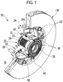
- the wheel bearing assembly may include a wheel bearing 10 and a brake disc 100 fastened to the wheel bearing 10 so as to rotate as a unit.
- the brake disc 100 is fastened to the wheel bearing 10 by a plurality of disc bolts 110 so that the brake disc 100 can be separated from the wheel bearing 10 in case the brake disc 100 is repaired or replaced due to wear, etc.
- the wheel bearing 10 may include a wheel hub 20, an inner race 30, an outer race 40, and rolling bodies 50.
- the wheel hub 20 may include a cylindrical portion 22 having two sides that are open and face opposite directions along an axis direction, and a flange portion 24 formed integrally with the cylindrical portion 22 so as to extend radially outward from the cylindrical portion 22.
- the inner race 30 may be inserted to penetrate the cylindrical portion 22 and may be fastened to the cylindrical portion 22 so as to rotate as a unit.
- Teeth and tooth grooves may be formed on a portion of the inner circumferential surface of the cylindrical portion 22 to extend along the axial direction.
- the teeth and the tooth grooves may be alternately disposed in the circumferential direction to form an axial spline 23.
- the inner race 30 may include a cylindrical portion 32 having two sides that are open and face opposite directions along the axis direction, and having an outer circumferential surface.
- An axial spline 34 may also be formed on a portion of the outer circumferential surface of the cylindrical portion 32 of the inner race 30 facing a portion of the inner circumferential surface of the cylindrical portion 22 of the wheel hub 20 in a state in which the inner race 30 is inserted to penetrate the cylindrical portion 22 of the wheel hub 20.
- the axial spline 34 of the inner race 30 may have a structure in which teeth and tooth grooves corresponding to the teeth and the tooth grooves of the axial spline 23 of the wheel hub 20 are formed to extend in the axial direction and are alternately disposed in the circumferential direction.
- the inner race 30 when the inner race 30 is inserted into and assembled with the cylindrical portion 22 of the wheel hub 20, if the axial spline 23 of the wheel hub 20 is meshed and coupled with the axial spline 34 of the inner race 30, the inner race 30 and the wheel hub 20 may be coupled together so as to rotate as a unit due to the coupling of the axial splines 23 and 34.
- a face spline 36 may be formed on one axial end surface of the inner race 30.
- the face spline 36 may have a structure in which teeth and tooth grooves are formed on one end surface of the inner race 30 so as to extend radially outward and are alternately disposed in the circumferential direction.
- a driving member may be coupled with the face spline 36 of the inner race 30, for example a face spline of a constant velocity joint receiving a torque from an engine may be meshed and coupled with the face spline 36 of the inner race 30 so that the inner race 30 and the constant velocity joint rotate as a unit.
- the torque of the engine transmitted to the inner race 30 through the constant velocity joint is transmitted to the wheel hub 20.
- a vehicle wheel (not shown) is fastened to the wheel hub 20 so that the torque of the engine is transmitted to the vehicle wheel via the constant velocity joint, the inner race 30, and the wheel hub 20.
- a pilot 21 is formed on one end surface of the cylindrical portion 22 of the wheel hub 20 to extend in the axial direction, and serves as an assembly guide when the vehicle wheel is fastened to and assembled with the wheel hub 20.
- a plurality of axially-penetrating hub bolts 26 is fastened to the flange portion 24 of the wheel hub 20.
- the hub bolts 26 are fastened to the vehicle wheel so that the wheel hub 20 and the vehicle wheel are coupled to rotate as a unit due to the fastening of the hub bolts 26.
- a wheel hub raceway surface and an inner race raceway surface are formed on a portion of the outer circumferential surface of the cylindrical portion 22 of the wheel hub 20 and a portion of the outer circumferential surface of the cylindrical portion 32 of the inner race 30, respectively.
- the rolling bodies 50 may be seated on and rotatably supported by the wheel hub raceway surface and the inner race raceway surface.
- the rolling bodies 50 are ball rolling bodies disposed in the circumferential direction so that a plurality of the rolling bodies form a row and disposed to be spaced apart from each other in the axial direction.
- the present invention is not limited thereto and a single-row of rolling bodies or rolling bodies having a shape other than a ball shape may be installed.
- the outer race 40 may include a cylindrical portion having two sides that are open and face opposite directions along the axis direction, and may be fixedly mounted to a non-rotating body such as a knuckle of a vehicle (not shown) or the like.
- the inner diameter of the cylindrical portion of the outer race 40 is formed to be larger than the outer diameter of the cylindrical portion 32 of the inner race 30 and the outer diameter of the cylindrical portion 22 of the wheel hub 20.
- seals 60 may be installed at the inlet of the separation space between the outer race 40 and the inner race 30 and at the inlet of the separation space between the outer race 40 and the wheel hub 20, respectively.
- the flange portion 24 of the wheel hub 20 may have a shape widening radially outward from the cylindrical portion 22 and continuously extending in the circumferential direction.
- Weight reducing portions 24a having a reduced thickness in the axial direction may be formed in the flange portion 24.
- a head portion 24b may be integrally formed to continuously extend in the circumferential direction along radial outer edges of the weight reducing portions 24a.
- the head portion 24b may be formed to extend in the axial direction and may be formed to have a thickness larger than the thickness of the weight reducing portions 24a.
- Fastening protrusion portions 24c protruding radially outward may be formed on the radial outer circumferential surface of the head portion 24b.
- the fastening protrusion portions 24c may include a plurality of fastening protrusion portions formed at fixed intervals in the circumferential direction.
- Fastening screw holes penetrating in the axial direction may be formed in the fastening protrusion portions 24c so that the disc bolts 110 may be mounted to the fastening screw holes and fastened to the brake disc 100.
- the head portion 24b and the fastening protrusion portions 24c may be integrally formed with the cylindrical portion 22 through a forging process, the productivity for the wheel hub 20 can be improved and an increase in rigidity can be realized.
- the wheel hub 20 may be made through a forging process using a steel (carbon steel) material, for example, S55CR.
- a steel (carbon steel) material for example, S55CR.
- the forging productivity for the wheel hub 20 may be improved by adjusting the position and depth of the weight reducing portions 24a.
- the brake disc 100 may include two sliding portions 102 generating frictional brake force by selectively coming into contact with brake pads (friction materials), not shown, in response to a braking operation.
- the two sliding portions 102 are disposed axially spaced apart from one another.
- a plurality of ribs 104 may be formed between the sliding portions 102, and the two sliding portions 102 may be integrally connected through the ribs 104.
- the plurality of ribs 104 may be disposed at fixed intervals in the circumferential direction to form air passages between the ribs 104. By facilitating smooth air circulation through the air passages, the air cooling effect of the brake disc 100 can be improved.
- Fastening protrusion portions 106 may be formed to protrude radially inward from the radial inner edge of one of the sliding portions 102.
- the fastening protrusion portions 106 may include a plurality of fastening protrusion portions formed to be spaced apart by fixed intervals in the circumferential direction.
- Fastening screw holes may be formed in the respective fastening protrusion portions 106 to penetrate them.
- the respective fastening protrusion portions 106 may be formed to continuously extend from the radial inner end surfaces of the plurality of ribs 104 and thus increase the rigidity of the fastening protrusion portions 106.
- the fastening protrusion portions 106 of the brake disc 100 may be formed in numbers corresponding to those of the fastening protrusion portions 24c of the wheel hub 20.
- the wheel hub 20 and the brake disc 100 may be fastened together by inserting the disc bolts 110 to penetrate the respective fastening protrusion portions 24c and 106 and fastening them in a state in which the fastening protrusion portions 106 of the brake disc 100 are brought into contact with the fastening protrusion portions 24c of the wheel hub 20.
- a seating protrusion 24d axially protruding beyond the fastening protrusion portions 24c and continuously extending in the circumferential direction may be formed in the head portion 24b of the wheel hub 20 so that the fastening screw holes of the fastening protrusion portions 24c of the wheel hub 20 and the fastening screw holes of the fastening protrusion portions 106 of the brake disc 100 can be easily aligned in the radial direction.
- the fastening screw holes of the fastening protrusion portions 24c of the wheel hub 20 and the fastening screw holes of the fastening protrusion portions 106 of the brake disc 100 are automatically aligned to radially coincide with each other.
- the fastening work using the wheel hub 20 and the disc bolts 110 of the brake disc 110 is simplified.
- the number of the fastening protrusion portions 24c of the wheel hub 20 and the fastening protrusion portions 106 of the brake disc 100 is from five to ten, it is possible to fasten the brake disc 100 to the wheel hub 20 so that the brake disc 100 is stably supported on the wheel hub 20. In addition, it is possible to enhance the ventilation effect due to the smooth air flow through the air passages formed between the fastening protrusion portions 106 of the brake disc 100.
- the brake disc 100 may be made by a casting method using, for example, a grey cast iron material.
- a reduction in the material of the brake disc 100 and a reduction in the replacement cost associated with replacing the brake disc 100 is facilitated by reducing the weight and size of the brake disc 100 having a relatively shorter lifespan than the wheel bearing 10 having a long lifespan.
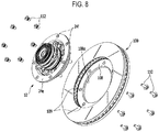
- the brake disc 100 is assembled by fitting it towards the side of the wheel bearing 10 where the hub bolts 26 of the wheel bearing 10 protrude. At this time, as shown in FIG. 4 , the brake disc 100 is assembled so that the fastening protrusion portions 106 of the brake disc 100 are positioned in the spaces between the fastening protrusion portions 24c of the wheel bearing 10.
- the fastening protrusion portions 24c and 106 are assembled such that they do not interfere with one another.
- the fastening protrusion portions 106 of the brake disc 100 and the fastening protrusion portions 24c of the wheel bearing 10 axially overlap and coincide with one another. If, in this state, the plurality of disc bolts 110 are inserted through respective fastening screw holes and fastened, the mutual assembly of the brake disc 100 and the wheel bearing 10 is completed.
- the disc bolts 110 may be fastened in the direction opposite to the assembly direction of the brake disc 100.
- the aforementioned assembly of the brake disc 100 and the wheel bearing 10 can be performed from both directions, at the inner side or the outer side in relation to the width direction of a vehicle, so that the assembly productivity, maintenability, and serviceability can be improved.
- the weight reducing portions 24a of the wheel hub 20 are illustrated as being formed at four locations circumferentially spaced apart from one another, the weight reducing portions 24a may be formed in a number greater than or less than four.
- Reinforcing ribs 24g may be positioned between the weight reducing portions 24a, and fastening holes to which the hub bolts 26 are fastened may be formed in the reinforcing ribs 24g.
- the fastening holes of the hub bolts 26 are located between the fastening protrusion portions 24c such that the overall fastening rigidity of the wheel hub 20 may be increased.
- a brake disc 200 may include two sliding portions 210 formed in a disc shape and disposed axially spaced apart from one another, and a plurality of ribs 220 formed in an axial separation space between the two sliding portions 210.
- the two sliding portions 210 may be integrally connected to each other by the plurality of ribs 220.
- the plurality of ribs 220 are formed in a predetermined shape and are disposed axially and circumferentially spaced apart from one another. Air passages 230 allowing an air flow may be formed between the plurality of ribs 220.
- the plurality of ribs 220 may have various shapes such as a triangular shape, a quadrangular shape, a diamond shape or the like.
- the air passages 230 may be formed in various shapes such as a triangular shape, a quadrangular shape, a diamond shape or the like, according to the form of arrangement of the plurality of ribs 220.
- Fastening protrusion portions 240 may be formed at the radial inner edge of one of the sliding portions 210 so as to protrude radially inward.
- the fastening protrusion portions 240 may include a plurality of fastening protrusion portions formed at fixed intervals in the circumferential direction.
- the fastening protrusion portions 240 may be fastened to the fastening protrusion portions 24c of the wheel hub 20 by the disc bolts 110.
- the fastening protrusion portions 240 may be formed to have a continuous structure with the ribs 220a.
- some inner ribs 220a among the plurality of ribs 220 may include a plurality of ribs formed at fixed intervals along the radial inner edge of the sliding portion 210.
- the fastening protrusion portions 240 may be formed to continuously extend from the inner ribs 220a.
- the brake disc 200 may improve the air flowability through the air passages 230 having various shapes.
- outflow ports 242 formed between the inner ribs 220a are formed to have a wider width than the air passages 230.
- the heat dissipation capability of the brake disc 200 may be increased by enhancing the flowability of air.
- the brake disc 200 may be made by a casting method using a grey cast iron material.
- a wheel bearing assembly according to another embodiment of the present invention is different in configuration in that the wheel hub 20 is press-fitted into the inner race 130 and coupled thereto.
- an orbital forming portion 25 bent radially outward is formed at one axial end portion of the wheel hub 20.
- the orbital forming portion 25 may be coupled so as to engage with a shoulder 132 formed in the inner race.
- a substantially ring-shaped fastening portion 108 is formed along the radial inner edge of the sliding portion 102 of the brake disc 100.
- a plurality of fastening holes 109 are formed along the circumferential direction by penetrating the fastening portion 108.
- Disc bolts 110 are inserted into the fastening holes 109 and are fastened to the fastening holes 24f of the fastening portion 24e of the wheel hub 20, such that the wheel hub 20 and the brake disc 100 may be fastened to each other.
- the fastening portion 24e of the wheel hub 20 may have a ring shape continuously extending in the circumferential direction.
- the fastening holes 24f may include a plurality of fastening holes formed at fixed intervals along the circumferential direction.
- the inner edge 108a of the fastening portion 108 of the brake disc 100 may come into surface contact with the outer circumferential surface of the wheel hub 20 and may serve as a guide for assembling the brake disc 100 and the wheel hub 20.
- flush head disc bolts 110 may be used as the disc bolts 110 to fasten the brake disc 100 and the wheel hub 20.
Landscapes
- Engineering & Computer Science (AREA)
- Mechanical Engineering (AREA)
- General Engineering & Computer Science (AREA)
- Rolling Contact Bearings (AREA)
- Braking Arrangements (AREA)
Applications Claiming Priority (1)
| Application Number | Priority Date | Filing Date | Title |
|---|---|---|---|
| PCT/KR2015/011199 WO2017069303A1 (fr) | 2015-10-22 | 2015-10-22 | Ensemble de roulement de roue |
Publications (2)
| Publication Number | Publication Date |
|---|---|
| EP3366491A1 true EP3366491A1 (fr) | 2018-08-29 |
| EP3366491A4 EP3366491A4 (fr) | 2019-05-15 |
Family
ID=58557462
Family Applications (1)
| Application Number | Title | Priority Date | Filing Date |
|---|---|---|---|
| EP15906754.5A Withdrawn EP3366491A4 (fr) | 2015-10-22 | 2015-10-22 | Ensemble de roulement de roue |
Country Status (4)
| Country | Link |
|---|---|
| US (1) | US10189309B2 (fr) |
| EP (1) | EP3366491A4 (fr) |
| CN (1) | CN107428199A (fr) |
| WO (1) | WO2017069303A1 (fr) |
Families Citing this family (6)
| Publication number | Priority date | Publication date | Assignee | Title |
|---|---|---|---|---|
| CN109955649A (zh) * | 2017-12-26 | 2019-07-02 | Tvs电机股份有限公司 | 车轮组件 |
| CN108162683A (zh) * | 2017-12-28 | 2018-06-15 | 湖北三环车桥有限公司 | 用于商用车的螺钉式轮毂制动盘总成 |
| KR101965816B1 (ko) * | 2018-01-03 | 2019-04-05 | 주식회사 일진글로벌 | 베어링 허브와 브레이크 디스크의 조립체 및 이를 구비하는 휠 베어링 조립체 |
| TWI673186B (zh) * | 2018-09-21 | 2019-10-01 | 財團法人工業技術研究院 | 輪轂結構 |
| USD927384S1 (en) * | 2019-07-29 | 2021-08-10 | Christopher Oscroft | Free wheel hub adaptor |
| US11629765B2 (en) | 2020-05-15 | 2023-04-18 | Arvinmeritor Technology, Llc | Brake rotor |
Family Cites Families (41)
| Publication number | Priority date | Publication date | Assignee | Title |
|---|---|---|---|---|
| GB127685A (en) * | 1918-03-06 | 1919-06-06 | Dunlop Rubber Co | Improvements in or relating to Means for Securing the Discs of Disc Wheels to the Wheel Hubs and to similar Coupling or Securing Means. |
| NL164807C (nl) * | 1970-02-05 | 1981-02-16 | Skf Svenska Kullagerfab Ab | Voertuig met aangedreven en niet-aangedreven loop- wielen, voorzien van dezelfde lagereenheid. |
| US3757883A (en) * | 1971-02-03 | 1973-09-11 | Skf Nv | Wheel support for an engine propelled road vehicle |
| JPS63101338U (fr) * | 1986-12-19 | 1988-07-01 | ||
| GB8722349D0 (en) * | 1987-09-23 | 1987-10-28 | Lucas Ind Plc | Disc brakes |
| FR2723886B1 (fr) * | 1994-08-23 | 1996-11-29 | Peugeot | Dispositif d'assemblage pour fixer coaxialement une roue de vehicule automobile et un disque de frein sur un moyeu |
| IT1288720B1 (it) * | 1996-10-01 | 1998-09-24 | Skf Ind Spa | Mozzo o gruppo mozzo ruota che permette un migliore montaggio e smontaggio di un organo frenante. |
| WO1998038436A1 (fr) * | 1997-02-27 | 1998-09-03 | Varga Brakes, Inc. | Procede de fabrication d'un moyeu, d'un coussinet, et d'un ensemble disque de frein de vehicule |
| DE19744870A1 (de) * | 1997-10-10 | 1999-04-15 | Itt Mfg Enterprises Inc | Vormontage-Baueinheit für Kraftfahrzeuge |
| DE19839844A1 (de) * | 1998-09-02 | 2000-03-30 | Knorr Bremse Systeme | Bremsscheibe und zugehörige Achsnabe |
| DE10046705C1 (de) * | 2000-09-21 | 2002-07-25 | Knorr Bremse Systeme | Bremsscheiben-/Nabenverbindung für Fahrzeugscheibenbremsen |
| JP2002323056A (ja) * | 2001-04-24 | 2002-11-08 | Ntn Corp | 車輪軸受装置 |
| ATE287800T1 (de) * | 2001-04-30 | 2005-02-15 | Knorr Bremse Systeme | Radnabe |
| JP2003120735A (ja) * | 2001-10-17 | 2003-04-23 | Koyo Seiko Co Ltd | 車輪用転がり軸受装置およびその製造方法 |
| WO2003045712A1 (fr) * | 2001-11-27 | 2003-06-05 | Freni Brembo S.P.A. | Support de roue pour vehicules a freins a disque |
| DE10323310A1 (de) * | 2003-05-23 | 2004-12-16 | Fag Kugelfischer Ag | Bremsscheibeneinheit |
| EP1500524A3 (fr) * | 2003-07-25 | 2005-10-12 | Ntn Corporation | Dispositif de roulement de roue |
| JP2005306257A (ja) | 2004-04-23 | 2005-11-04 | Ntn Corp | ブレーキロータ付き車輪用軸受装置 |
| DE102004022372A1 (de) * | 2004-05-06 | 2005-12-01 | Bayerische Motoren Werke Ag | Fahrzeugrad mit einem Flanschteil, einer Radscheibe und einem Felgenabschnitt |
| ITTO20040316A1 (it) * | 2004-05-14 | 2004-08-14 | Skf Ab | Dispositivo di connessione di un cuscinetto volvente ad un corpo esterno |
| KR20060108280A (ko) | 2005-04-12 | 2006-10-17 | 주식회사 동아오토모티브 | 브레이크 디스크 및 그 조립방법 |
| US7958978B2 (en) * | 2007-08-09 | 2011-06-14 | Bwi Company Limited S.A. | Multi-disc brake hub assembly with disc slide pins |
| WO2009026458A1 (fr) * | 2007-08-22 | 2009-02-26 | Tech M3, Inc. | Disque de frein et procédé de fabrication de celui-ci |
| JP5134340B2 (ja) * | 2007-11-06 | 2013-01-30 | Ntn株式会社 | 車輪用軸受装置 |
| JP5109852B2 (ja) * | 2008-07-22 | 2012-12-26 | 株式会社ジェイテクト | ハブユニットのフランジ面振れ測定治具及び面振れ測定方法 |
| KR101484812B1 (ko) * | 2008-07-26 | 2015-01-20 | 아크티에볼라겟 에스케이에프 | 휠 베어링 유닛 |
| KR20120002148A (ko) | 2010-06-30 | 2012-01-05 | 엔에이치엔(주) | 자동으로 컨텐츠를 추천하는 모바일 시스템, 컨텐츠 추천 시스템 및 컨텐츠 추천 방법 |
| KR20120002148U (ko) * | 2010-09-15 | 2012-03-23 | 주식회사 프릭사 | 경량 브레이크 디스크구조 |
| DE112011104823T5 (de) * | 2011-03-04 | 2013-10-31 | Iljin Bearing | Radlageranordnung |
| US9897154B2 (en) * | 2011-03-31 | 2018-02-20 | Gunite Corporation | Disk brake hub assembly |
| US8950556B2 (en) * | 2011-03-31 | 2015-02-10 | Gunite Corporation | Disk brake hub assembly |
| DE102011007110A1 (de) * | 2011-04-11 | 2012-10-11 | Bayerische Motoren Werke Aktiengesellschaft | Radlager-Baugruppe eines Fahrzeugs |
| KR101283018B1 (ko) | 2011-05-18 | 2013-07-08 | 현대자동차주식회사 | 이종재질의 브레이크 디스크 |
| FR3004995B1 (fr) * | 2013-04-30 | 2015-06-05 | Ntn Snr Roulements | Montage d’un ensemble disque de frein / jante de roue de vehicule automobile sur un systeme d’entrainement en rotation dudit ensemble |
| KR101532078B1 (ko) | 2013-12-04 | 2015-06-29 | 주식회사 일진글로벌 | 분리 가능한 브레이크 디스크, 이를 구비한 휠 베어링 조립체 및 브레이크 디스크의 런아웃 규제 방법 |
| WO2015106760A1 (fr) * | 2014-01-15 | 2015-07-23 | ThyssenKrupp Carbon Components GmbH | Roue de véhicule comprenant une liaison entre une jante présentant un creux de jante en matériau renforcé par des fibres et un disque de roue |
| US20160002516A1 (en) * | 2014-07-01 | 2016-01-07 | Taiwan Fluoro Technology Co., Ltd. | Water-repellent and oil-repellent agent |
| US20160025165A1 (en) * | 2014-07-24 | 2016-01-28 | Bendix Spicer Foundation Brake Llc | Brake Disc Mounting Arrangement |
| CN204140681U (zh) * | 2014-10-13 | 2015-02-04 | 无锡创明传动工程有限公司 | 一种大型号膜盘联接结构 |
| US9694627B2 (en) * | 2015-06-29 | 2017-07-04 | Aktiebolaget Skf | Hub-bearing having a light alloy rotor-hub |
| ITUB20156263A1 (it) * | 2015-12-03 | 2017-06-03 | Campagnolo Srl | Mozzo per una ruota di bicicletta |
-
2015
- 2015-10-22 EP EP15906754.5A patent/EP3366491A4/fr not_active Withdrawn
- 2015-10-22 US US15/554,039 patent/US10189309B2/en active Active
- 2015-10-22 WO PCT/KR2015/011199 patent/WO2017069303A1/fr active Application Filing
- 2015-10-22 CN CN201580077794.4A patent/CN107428199A/zh active Pending
Also Published As
| Publication number | Publication date |
|---|---|
| CN107428199A (zh) | 2017-12-01 |
| EP3366491A4 (fr) | 2019-05-15 |
| WO2017069303A1 (fr) | 2017-04-27 |
| US20180043733A1 (en) | 2018-02-15 |
| US10189309B2 (en) | 2019-01-29 |
Similar Documents
| Publication | Publication Date | Title |
|---|---|---|
| US10189309B2 (en) | Wheel bearing assembly | |
| KR101728024B1 (ko) | 휠 허브, 브레이크 디스크, 및 이를 구비한 휠 베어링 조립체 | |
| US20060033381A1 (en) | Bearing apparatus for a wheel of vehicle | |
| JP5227158B2 (ja) | 転がり軸受の内輪およびそれを備えた車輪用軸受装置 | |
| WO2017010555A1 (fr) | Dispositif de palier pour une roue de véhicule | |
| US20050231025A1 (en) | Wheel support rolling bearing unit and manufacturing method therefor | |
| JP2004322834A (ja) | 車輪用回転支持装置 | |
| KR101573399B1 (ko) | 휠 베어링 조립체 | |
| KR101532078B1 (ko) | 분리 가능한 브레이크 디스크, 이를 구비한 휠 베어링 조립체 및 브레이크 디스크의 런아웃 규제 방법 | |
| JP6366233B2 (ja) | 車輪用軸受装置 | |
| WO2019026358A1 (fr) | Palier d'unité de moyeu, son procédé de fabrication, véhicule à moteur et son procédé de fabrication | |
| JP2002347402A (ja) | 車輪用軸受ユニットとその製造方法 | |
| JP2010089664A (ja) | 車輪用軸受装置 | |
| US20200318681A1 (en) | Wheel bearing device and method for manufacturing said device | |
| JP2017047716A (ja) | 車輪用軸受装置 | |
| JP2018197598A (ja) | 駆動輪用ハブユニット | |
| JP2017001524A (ja) | ハブユニット及びハブユニットの製造方法 | |
| JP4356381B2 (ja) | 車輪用軸受ユニットの製造方法 | |
| KR101728031B1 (ko) | 휠 베어링 및 그 제작 방법 | |
| JP5891720B2 (ja) | ハブユニット軸受 | |
| US20230003256A1 (en) | Wheel bearing device and method for manufacturing said device | |
| JP2009257375A (ja) | 車輪用軸受装置 | |
| JP5574146B2 (ja) | 車輪用転がり軸受け装置 | |
| JP5141114B2 (ja) | 車輪支持用転がり軸受ユニット | |
| JP2017094978A (ja) | ハブ輪及び車輪支持用転がり軸受ユニット |
Legal Events
| Date | Code | Title | Description |
|---|---|---|---|
| PUAI | Public reference made under article 153(3) epc to a published international application that has entered the european phase |
Free format text: ORIGINAL CODE: 0009012 |
|
| 17P | Request for examination filed |
Effective date: 20170822 |
|
| AK | Designated contracting states |
Kind code of ref document: A1 Designated state(s): AL AT BE BG CH CY CZ DE DK EE ES FI FR GB GR HR HU IE IS IT LI LT LU LV MC MK MT NL NO PL PT RO RS SE SI SK SM TR |
|
| AX | Request for extension of the european patent |
Extension state: BA ME |
|
| DAV | Request for validation of the european patent (deleted) | ||
| DAX | Request for extension of the european patent (deleted) | ||
| A4 | Supplementary search report drawn up and despatched |
Effective date: 20190412 |
|
| RIC1 | Information provided on ipc code assigned before grant |
Ipc: B60B 21/08 20060101ALI20190408BHEP Ipc: B60B 27/00 20060101ALI20190408BHEP Ipc: F16C 19/18 20060101ALI20190408BHEP Ipc: B60B 35/18 20060101AFI20190408BHEP |
|
| 17Q | First examination report despatched |
Effective date: 20200618 |
|
| STAA | Information on the status of an ep patent application or granted ep patent |
Free format text: STATUS: THE APPLICATION HAS BEEN WITHDRAWN |
|
| 18W | Application withdrawn |
Effective date: 20201216 |