EP3361487B1 - Feuille magnétique, module la comprenant, et dispositif portatif la comprenant - Google Patents
Feuille magnétique, module la comprenant, et dispositif portatif la comprenant Download PDFInfo
- Publication number
- EP3361487B1 EP3361487B1 EP16853889.0A EP16853889A EP3361487B1 EP 3361487 B1 EP3361487 B1 EP 3361487B1 EP 16853889 A EP16853889 A EP 16853889A EP 3361487 B1 EP3361487 B1 EP 3361487B1
- Authority
- EP
- European Patent Office
- Prior art keywords
- magnetic
- antenna
- magnetic sheet
- sheet
- thin film
- Prior art date
- Legal status (The legal status is an assumption and is not a legal conclusion. Google has not performed a legal analysis and makes no representation as to the accuracy of the status listed.)
- Active
Links
- 239000010409 thin film Substances 0.000 claims description 116
- 239000011247 coating layer Substances 0.000 claims description 113
- 238000009501 film coating Methods 0.000 claims description 112
- 239000010410 layer Substances 0.000 claims description 112
- 229910000859 α-Fe Inorganic materials 0.000 claims description 53
- 229910045601 alloy Inorganic materials 0.000 claims description 24
- 239000000956 alloy Substances 0.000 claims description 24
- 230000005540 biological transmission Effects 0.000 claims description 20
- 239000000696 magnetic material Substances 0.000 claims description 14
- 229920001971 elastomer Polymers 0.000 claims description 11
- 239000005060 rubber Substances 0.000 claims description 11
- 229920002943 EPDM rubber Polymers 0.000 claims description 9
- 238000004891 communication Methods 0.000 claims description 9
- 230000004907 flux Effects 0.000 claims description 8
- 229910017709 Ni Co Inorganic materials 0.000 claims description 7
- 229910003267 Ni-Co Inorganic materials 0.000 claims description 7
- 229910003262 Ni‐Co Inorganic materials 0.000 claims description 7
- 229910008423 Si—B Inorganic materials 0.000 claims description 7
- 239000002356 single layer Substances 0.000 claims description 7
- 229910017518 Cu Zn Inorganic materials 0.000 claims description 5
- 229910017752 Cu-Zn Inorganic materials 0.000 claims description 5
- 229910017943 Cu—Zn Inorganic materials 0.000 claims description 5
- 229910018605 Ni—Zn Inorganic materials 0.000 claims description 5
- TVZPLCNGKSPOJA-UHFFFAOYSA-N copper zinc Chemical compound [Cu].[Zn] TVZPLCNGKSPOJA-UHFFFAOYSA-N 0.000 claims description 4
- 229910017060 Fe Cr Inorganic materials 0.000 claims description 3
- 229910002544 Fe-Cr Inorganic materials 0.000 claims description 3
- 229910017082 Fe-Si Inorganic materials 0.000 claims description 3
- 229910017133 Fe—Si Inorganic materials 0.000 claims description 3
- 229910001030 Iron–nickel alloy Inorganic materials 0.000 claims description 3
- UPHIPHFJVNKLMR-UHFFFAOYSA-N chromium iron Chemical compound [Cr].[Fe] UPHIPHFJVNKLMR-UHFFFAOYSA-N 0.000 claims description 3
- 239000000203 mixture Substances 0.000 description 45
- 239000000853 adhesive Substances 0.000 description 41
- 230000001070 adhesive effect Effects 0.000 description 41
- 238000004519 manufacturing process Methods 0.000 description 41
- 239000010408 film Substances 0.000 description 28
- 230000001681 protective effect Effects 0.000 description 28
- 230000000704 physical effect Effects 0.000 description 27
- 238000000034 method Methods 0.000 description 25
- 239000012790 adhesive layer Substances 0.000 description 22
- ZWEHNKRNPOVVGH-UHFFFAOYSA-N 2-Butanone Chemical compound CCC(C)=O ZWEHNKRNPOVVGH-UHFFFAOYSA-N 0.000 description 21
- -1 or the like Polymers 0.000 description 21
- 229910000808 amorphous metal alloy Inorganic materials 0.000 description 20
- YXFVVABEGXRONW-UHFFFAOYSA-N Toluene Chemical compound CC1=CC=CC=C1 YXFVVABEGXRONW-UHFFFAOYSA-N 0.000 description 18
- 238000001723 curing Methods 0.000 description 18
- 239000000463 material Substances 0.000 description 17
- 150000001875 compounds Chemical class 0.000 description 16
- 230000035699 permeability Effects 0.000 description 16
- 230000015556 catabolic process Effects 0.000 description 14
- 238000006731 degradation reaction Methods 0.000 description 14
- 230000008569 process Effects 0.000 description 13
- 230000006378 damage Effects 0.000 description 12
- 239000002245 particle Substances 0.000 description 12
- 230000005855 radiation Effects 0.000 description 12
- 239000000523 sample Substances 0.000 description 12
- 238000007711 solidification Methods 0.000 description 12
- 230000008023 solidification Effects 0.000 description 12
- XEEYBQQBJWHFJM-UHFFFAOYSA-N iron Substances [Fe] XEEYBQQBJWHFJM-UHFFFAOYSA-N 0.000 description 11
- 229910052751 metal Inorganic materials 0.000 description 11
- 229920000642 polymer Polymers 0.000 description 11
- 229920005989 resin Polymers 0.000 description 11
- 239000011347 resin Substances 0.000 description 11
- 238000010586 diagram Methods 0.000 description 10
- 238000013467 fragmentation Methods 0.000 description 10
- 238000006062 fragmentation reaction Methods 0.000 description 10
- 239000002994 raw material Substances 0.000 description 10
- 239000002904 solvent Substances 0.000 description 10
- 239000012298 atmosphere Substances 0.000 description 9
- 229910052802 copper Inorganic materials 0.000 description 9
- 239000010949 copper Substances 0.000 description 9
- 239000002184 metal Substances 0.000 description 9
- 239000011701 zinc Substances 0.000 description 9
- RYGMFSIKBFXOCR-UHFFFAOYSA-N Copper Chemical compound [Cu] RYGMFSIKBFXOCR-UHFFFAOYSA-N 0.000 description 8
- PXHVJJICTQNCMI-UHFFFAOYSA-N Nickel Chemical compound [Ni] PXHVJJICTQNCMI-UHFFFAOYSA-N 0.000 description 8
- 230000000903 blocking effect Effects 0.000 description 8
- 230000032798 delamination Effects 0.000 description 8
- 239000010955 niobium Substances 0.000 description 8
- 239000002346 layers by function Substances 0.000 description 7
- 230000000052 comparative effect Effects 0.000 description 6
- 230000001747 exhibiting effect Effects 0.000 description 6
- 239000000945 filler Substances 0.000 description 6
- 229920000139 polyethylene terephthalate Polymers 0.000 description 6
- 239000005020 polyethylene terephthalate Substances 0.000 description 6
- 230000002265 prevention Effects 0.000 description 6
- 238000005452 bending Methods 0.000 description 5
- 230000008901 benefit Effects 0.000 description 5
- 238000001354 calcination Methods 0.000 description 5
- 238000006243 chemical reaction Methods 0.000 description 5
- 230000006870 function Effects 0.000 description 5
- 230000017525 heat dissipation Effects 0.000 description 5
- RAXXELZNTBOGNW-UHFFFAOYSA-N imidazole Natural products C1=CNC=N1 RAXXELZNTBOGNW-UHFFFAOYSA-N 0.000 description 5
- 230000008595 infiltration Effects 0.000 description 5
- 238000001764 infiltration Methods 0.000 description 5
- 229920003986 novolac Polymers 0.000 description 5
- 239000004709 Chlorinated polyethylene Substances 0.000 description 4
- XLOMVQKBTHCTTD-UHFFFAOYSA-N Zinc monoxide Chemical compound [Zn]=O XLOMVQKBTHCTTD-UHFFFAOYSA-N 0.000 description 4
- QVGXLLKOCUKJST-UHFFFAOYSA-N atomic oxygen Chemical compound [O] QVGXLLKOCUKJST-UHFFFAOYSA-N 0.000 description 4
- 239000011230 binding agent Substances 0.000 description 4
- IISBACLAFKSPIT-UHFFFAOYSA-N bisphenol A Chemical compound C=1C=C(O)C=CC=1C(C)(C)C1=CC=C(O)C=C1 IISBACLAFKSPIT-UHFFFAOYSA-N 0.000 description 4
- 229910052796 boron Inorganic materials 0.000 description 4
- 239000013078 crystal Substances 0.000 description 4
- 238000013461 design Methods 0.000 description 4
- 230000000694 effects Effects 0.000 description 4
- 238000005516 engineering process Methods 0.000 description 4
- 230000006872 improvement Effects 0.000 description 4
- 229910052759 nickel Inorganic materials 0.000 description 4
- 239000001301 oxygen Substances 0.000 description 4
- 229910052760 oxygen Inorganic materials 0.000 description 4
- 239000004593 Epoxy Substances 0.000 description 3
- 239000004698 Polyethylene Substances 0.000 description 3
- 239000004734 Polyphenylene sulfide Substances 0.000 description 3
- 239000004743 Polypropylene Substances 0.000 description 3
- NIXOWILDQLNWCW-UHFFFAOYSA-N acrylic acid group Chemical group C(C=C)(=O)O NIXOWILDQLNWCW-UHFFFAOYSA-N 0.000 description 3
- 229920000800 acrylic rubber Polymers 0.000 description 3
- 239000000654 additive Substances 0.000 description 3
- 230000003139 buffering effect Effects 0.000 description 3
- 239000003795 chemical substances by application Substances 0.000 description 3
- 239000011248 coating agent Substances 0.000 description 3
- 238000000576 coating method Methods 0.000 description 3
- 229910017052 cobalt Inorganic materials 0.000 description 3
- 239000010941 cobalt Substances 0.000 description 3
- GUTLYIVDDKVIGB-UHFFFAOYSA-N cobalt atom Chemical compound [Co] GUTLYIVDDKVIGB-UHFFFAOYSA-N 0.000 description 3
- 239000002131 composite material Substances 0.000 description 3
- 230000007797 corrosion Effects 0.000 description 3
- 238000005260 corrosion Methods 0.000 description 3
- 238000011156 evaluation Methods 0.000 description 3
- 230000006698 induction Effects 0.000 description 3
- 150000002500 ions Chemical class 0.000 description 3
- 239000007788 liquid Substances 0.000 description 3
- 229910052749 magnesium Inorganic materials 0.000 description 3
- 239000011777 magnesium Substances 0.000 description 3
- 229920002493 poly(chlorotrifluoroethylene) Polymers 0.000 description 3
- 229920000058 polyacrylate Polymers 0.000 description 3
- 229920001707 polybutylene terephthalate Polymers 0.000 description 3
- 239000005023 polychlorotrifluoroethylene (PCTFE) polymer Substances 0.000 description 3
- 229920000573 polyethylene Polymers 0.000 description 3
- 229920000069 polyphenylene sulfide Polymers 0.000 description 3
- 229920001155 polypropylene Polymers 0.000 description 3
- 229920001343 polytetrafluoroethylene Polymers 0.000 description 3
- 239000004810 polytetrafluoroethylene Substances 0.000 description 3
- 239000000843 powder Substances 0.000 description 3
- 239000000758 substrate Substances 0.000 description 3
- 229920001169 thermoplastic Polymers 0.000 description 3
- 229910052725 zinc Inorganic materials 0.000 description 3
- KXGFMDJXCMQABM-UHFFFAOYSA-N 2-methoxy-6-methylphenol Chemical compound [CH]OC1=CC=CC([CH])=C1O KXGFMDJXCMQABM-UHFFFAOYSA-N 0.000 description 2
- CSCPPACGZOOCGX-UHFFFAOYSA-N Acetone Chemical compound CC(C)=O CSCPPACGZOOCGX-UHFFFAOYSA-N 0.000 description 2
- IJGRMHOSHXDMSA-UHFFFAOYSA-N Atomic nitrogen Chemical compound N#N IJGRMHOSHXDMSA-UHFFFAOYSA-N 0.000 description 2
- 229920002799 BoPET Polymers 0.000 description 2
- VTYYLEPIZMXCLO-UHFFFAOYSA-L Calcium carbonate Chemical compound [Ca+2].[O-]C([O-])=O VTYYLEPIZMXCLO-UHFFFAOYSA-L 0.000 description 2
- CURLTUGMZLYLDI-UHFFFAOYSA-N Carbon dioxide Chemical compound O=C=O CURLTUGMZLYLDI-UHFFFAOYSA-N 0.000 description 2
- RTZKZFJDLAIYFH-UHFFFAOYSA-N Diethyl ether Chemical compound CCOCC RTZKZFJDLAIYFH-UHFFFAOYSA-N 0.000 description 2
- FYYHWMGAXLPEAU-UHFFFAOYSA-N Magnesium Chemical compound [Mg] FYYHWMGAXLPEAU-UHFFFAOYSA-N 0.000 description 2
- NTIZESTWPVYFNL-UHFFFAOYSA-N Methyl isobutyl ketone Chemical compound CC(C)CC(C)=O NTIZESTWPVYFNL-UHFFFAOYSA-N 0.000 description 2
- UIHCLUNTQKBZGK-UHFFFAOYSA-N Methyl isobutyl ketone Natural products CCC(C)C(C)=O UIHCLUNTQKBZGK-UHFFFAOYSA-N 0.000 description 2
- 229920000459 Nitrile rubber Polymers 0.000 description 2
- 229920002367 Polyisobutene Polymers 0.000 description 2
- 239000004721 Polyphenylene oxide Substances 0.000 description 2
- ATUOYWHBWRKTHZ-UHFFFAOYSA-N Propane Chemical compound CCC ATUOYWHBWRKTHZ-UHFFFAOYSA-N 0.000 description 2
- VYPSYNLAJGMNEJ-UHFFFAOYSA-N Silicium dioxide Chemical compound O=[Si]=O VYPSYNLAJGMNEJ-UHFFFAOYSA-N 0.000 description 2
- HCHKCACWOHOZIP-UHFFFAOYSA-N Zinc Chemical compound [Zn] HCHKCACWOHOZIP-UHFFFAOYSA-N 0.000 description 2
- 229910052782 aluminium Inorganic materials 0.000 description 2
- 229940106691 bisphenol a Drugs 0.000 description 2
- 239000001913 cellulose Substances 0.000 description 2
- 229920002678 cellulose Polymers 0.000 description 2
- 229910052804 chromium Inorganic materials 0.000 description 2
- 239000008199 coating composition Substances 0.000 description 2
- 229910000428 cobalt oxide Inorganic materials 0.000 description 2
- IVMYJDGYRUAWML-UHFFFAOYSA-N cobalt(ii) oxide Chemical compound [Co]=O IVMYJDGYRUAWML-UHFFFAOYSA-N 0.000 description 2
- 238000002425 crystallisation Methods 0.000 description 2
- 230000008025 crystallization Effects 0.000 description 2
- JHIVVAPYMSGYDF-UHFFFAOYSA-N cyclohexanone Chemical compound O=C1CCCCC1 JHIVVAPYMSGYDF-UHFFFAOYSA-N 0.000 description 2
- 238000009826 distribution Methods 0.000 description 2
- 239000005038 ethylene vinyl acetate Substances 0.000 description 2
- JEIPFZHSYJVQDO-UHFFFAOYSA-N ferric oxide Chemical compound O=[Fe]O[Fe]=O JEIPFZHSYJVQDO-UHFFFAOYSA-N 0.000 description 2
- 239000007789 gas Substances 0.000 description 2
- 230000020169 heat generation Effects 0.000 description 2
- QSHDDOUJBYECFT-UHFFFAOYSA-N mercury Chemical compound [Hg] QSHDDOUJBYECFT-UHFFFAOYSA-N 0.000 description 2
- 150000002739 metals Chemical class 0.000 description 2
- 238000002156 mixing Methods 0.000 description 2
- 229920005615 natural polymer Polymers 0.000 description 2
- 229910000480 nickel oxide Inorganic materials 0.000 description 2
- 230000003647 oxidation Effects 0.000 description 2
- 238000007254 oxidation reaction Methods 0.000 description 2
- GNRSAWUEBMWBQH-UHFFFAOYSA-N oxonickel Chemical compound [Ni]=O GNRSAWUEBMWBQH-UHFFFAOYSA-N 0.000 description 2
- 239000003002 pH adjusting agent Substances 0.000 description 2
- 229920001568 phenolic resin Polymers 0.000 description 2
- 239000005011 phenolic resin Substances 0.000 description 2
- 229920001200 poly(ethylene-vinyl acetate) Polymers 0.000 description 2
- 229920002857 polybutadiene Polymers 0.000 description 2
- 229920000570 polyether Polymers 0.000 description 2
- 229920002215 polytrimethylene terephthalate Polymers 0.000 description 2
- 239000004814 polyurethane Substances 0.000 description 2
- 238000003825 pressing Methods 0.000 description 2
- 230000009467 reduction Effects 0.000 description 2
- 230000008054 signal transmission Effects 0.000 description 2
- 229910052709 silver Inorganic materials 0.000 description 2
- 238000005245 sintering Methods 0.000 description 2
- 239000007787 solid Substances 0.000 description 2
- 239000007790 solid phase Substances 0.000 description 2
- 239000000126 substance Substances 0.000 description 2
- 230000002459 sustained effect Effects 0.000 description 2
- 229920001059 synthetic polymer Polymers 0.000 description 2
- 229920001187 thermosetting polymer Polymers 0.000 description 2
- 239000004634 thermosetting polymer Substances 0.000 description 2
- 239000011787 zinc oxide Substances 0.000 description 2
- NWUYHJFMYQTDRP-UHFFFAOYSA-N 1,2-bis(ethenyl)benzene;1-ethenyl-2-ethylbenzene;styrene Chemical compound C=CC1=CC=CC=C1.CCC1=CC=CC=C1C=C.C=CC1=CC=CC=C1C=C NWUYHJFMYQTDRP-UHFFFAOYSA-N 0.000 description 1
- WZCQRUWWHSTZEM-UHFFFAOYSA-N 1,3-phenylenediamine Chemical compound NC1=CC=CC(N)=C1 WZCQRUWWHSTZEM-UHFFFAOYSA-N 0.000 description 1
- GDXHBFHOEYVPED-UHFFFAOYSA-N 1-(2-butoxyethoxy)butane Chemical compound CCCCOCCOCCCC GDXHBFHOEYVPED-UHFFFAOYSA-N 0.000 description 1
- KJCVRFUGPWSIIH-UHFFFAOYSA-N 1-naphthol Chemical compound C1=CC=C2C(O)=CC=CC2=C1 KJCVRFUGPWSIIH-UHFFFAOYSA-N 0.000 description 1
- RNFJDJUURJAICM-UHFFFAOYSA-N 2,2,4,4,6,6-hexaphenoxy-1,3,5-triaza-2$l^{5},4$l^{5},6$l^{5}-triphosphacyclohexa-1,3,5-triene Chemical compound N=1P(OC=2C=CC=CC=2)(OC=2C=CC=CC=2)=NP(OC=2C=CC=CC=2)(OC=2C=CC=CC=2)=NP=1(OC=1C=CC=CC=1)OC1=CC=CC=C1 RNFJDJUURJAICM-UHFFFAOYSA-N 0.000 description 1
- XNWFRZJHXBZDAG-UHFFFAOYSA-N 2-METHOXYETHANOL Chemical compound COCCO XNWFRZJHXBZDAG-UHFFFAOYSA-N 0.000 description 1
- NQBXSWAWVZHKBZ-UHFFFAOYSA-N 2-butoxyethyl acetate Chemical compound CCCCOCCOC(C)=O NQBXSWAWVZHKBZ-UHFFFAOYSA-N 0.000 description 1
- QTWJRLJHJPIABL-UHFFFAOYSA-N 2-methylphenol;3-methylphenol;4-methylphenol Chemical compound CC1=CC=C(O)C=C1.CC1=CC=CC(O)=C1.CC1=CC=CC=C1O QTWJRLJHJPIABL-UHFFFAOYSA-N 0.000 description 1
- WJQOZHYUIDYNHM-UHFFFAOYSA-N 2-tert-Butylphenol Chemical compound CC(C)(C)C1=CC=CC=C1O WJQOZHYUIDYNHM-UHFFFAOYSA-N 0.000 description 1
- HLBLWEWZXPIGSM-UHFFFAOYSA-N 4-Aminophenyl ether Chemical compound C1=CC(N)=CC=C1OC1=CC=C(N)C=C1 HLBLWEWZXPIGSM-UHFFFAOYSA-N 0.000 description 1
- WUPRYUDHUFLKFL-UHFFFAOYSA-N 4-[3-(4-aminophenoxy)phenoxy]aniline Chemical compound C1=CC(N)=CC=C1OC1=CC=CC(OC=2C=CC(N)=CC=2)=C1 WUPRYUDHUFLKFL-UHFFFAOYSA-N 0.000 description 1
- JCRRFJIVUPSNTA-UHFFFAOYSA-N 4-[4-(4-aminophenoxy)phenoxy]aniline Chemical compound C1=CC(N)=CC=C1OC(C=C1)=CC=C1OC1=CC=C(N)C=C1 JCRRFJIVUPSNTA-UHFFFAOYSA-N 0.000 description 1
- HYDATEKARGDBKU-UHFFFAOYSA-N 4-[4-[4-(4-aminophenoxy)phenyl]phenoxy]aniline Chemical group C1=CC(N)=CC=C1OC1=CC=C(C=2C=CC(OC=3C=CC(N)=CC=3)=CC=2)C=C1 HYDATEKARGDBKU-UHFFFAOYSA-N 0.000 description 1
- UTDAGHZGKXPRQI-UHFFFAOYSA-N 4-[4-[4-(4-aminophenoxy)phenyl]sulfonylphenoxy]aniline Chemical compound C1=CC(N)=CC=C1OC1=CC=C(S(=O)(=O)C=2C=CC(OC=3C=CC(N)=CC=3)=CC=2)C=C1 UTDAGHZGKXPRQI-UHFFFAOYSA-N 0.000 description 1
- QTBSBXVTEAMEQO-UHFFFAOYSA-M Acetate Chemical compound CC([O-])=O QTBSBXVTEAMEQO-UHFFFAOYSA-M 0.000 description 1
- ZOXJGFHDIHLPTG-UHFFFAOYSA-N Boron Chemical compound [B] ZOXJGFHDIHLPTG-UHFFFAOYSA-N 0.000 description 1
- QPLDLSVMHZLSFG-UHFFFAOYSA-N Copper oxide Chemical compound [Cu]=O QPLDLSVMHZLSFG-UHFFFAOYSA-N 0.000 description 1
- 239000005751 Copper oxide Substances 0.000 description 1
- 229910020521 Co—Zn Inorganic materials 0.000 description 1
- 229910017816 Cu—Co Inorganic materials 0.000 description 1
- MQJKPEGWNLWLTK-UHFFFAOYSA-N Dapsone Chemical compound C1=CC(N)=CC=C1S(=O)(=O)C1=CC=C(N)C=C1 MQJKPEGWNLWLTK-UHFFFAOYSA-N 0.000 description 1
- JOYRKODLDBILNP-UHFFFAOYSA-N Ethyl urethane Chemical compound CCOC(N)=O JOYRKODLDBILNP-UHFFFAOYSA-N 0.000 description 1
- YCKRFDGAMUMZLT-UHFFFAOYSA-N Fluorine atom Chemical compound [F] YCKRFDGAMUMZLT-UHFFFAOYSA-N 0.000 description 1
- GYHNNYVSQQEPJS-UHFFFAOYSA-N Gallium Chemical compound [Ga] GYHNNYVSQQEPJS-UHFFFAOYSA-N 0.000 description 1
- 108010010803 Gelatin Proteins 0.000 description 1
- 244000043261 Hevea brasiliensis Species 0.000 description 1
- 229920000877 Melamine resin Polymers 0.000 description 1
- NMEIAKUUOAHTCI-UHFFFAOYSA-N N#C[Zn](C#N)(C#N)(C#N)(C#N)C#N Chemical compound N#C[Zn](C#N)(C#N)(C#N)(C#N)C#N NMEIAKUUOAHTCI-UHFFFAOYSA-N 0.000 description 1
- ISWSIDIOOBJBQZ-UHFFFAOYSA-N Phenol Chemical compound OC1=CC=CC=C1 ISWSIDIOOBJBQZ-UHFFFAOYSA-N 0.000 description 1
- OAICVXFJPJFONN-UHFFFAOYSA-N Phosphorus Chemical compound [P] OAICVXFJPJFONN-UHFFFAOYSA-N 0.000 description 1
- 239000004952 Polyamide Substances 0.000 description 1
- 239000004962 Polyamide-imide Substances 0.000 description 1
- 239000004693 Polybenzimidazole Substances 0.000 description 1
- 239000005062 Polybutadiene Substances 0.000 description 1
- 239000004697 Polyetherimide Substances 0.000 description 1
- 239000004954 Polyphthalamide Substances 0.000 description 1
- 239000004793 Polystyrene Substances 0.000 description 1
- 229920009405 Polyvinylidenefluoride (PVDF) Film Polymers 0.000 description 1
- 229920002472 Starch Polymers 0.000 description 1
- GWEVSGVZZGPLCZ-UHFFFAOYSA-N Titan oxide Chemical compound O=[Ti]=O GWEVSGVZZGPLCZ-UHFFFAOYSA-N 0.000 description 1
- 238000003848 UV Light-Curing Methods 0.000 description 1
- XSQUKJJJFZCRTK-UHFFFAOYSA-N Urea Chemical compound NC(N)=O XSQUKJJJFZCRTK-UHFFFAOYSA-N 0.000 description 1
- FDLQZKYLHJJBHD-UHFFFAOYSA-N [3-(aminomethyl)phenyl]methanamine Chemical compound NCC1=CC=CC(CN)=C1 FDLQZKYLHJJBHD-UHFFFAOYSA-N 0.000 description 1
- GDFCWFBWQUEQIJ-UHFFFAOYSA-N [B].[P] Chemical compound [B].[P] GDFCWFBWQUEQIJ-UHFFFAOYSA-N 0.000 description 1
- 150000008065 acid anhydrides Chemical class 0.000 description 1
- 230000002378 acidificating effect Effects 0.000 description 1
- 239000004676 acrylonitrile butadiene styrene Substances 0.000 description 1
- 230000009471 action Effects 0.000 description 1
- 238000005054 agglomeration Methods 0.000 description 1
- 230000002776 aggregation Effects 0.000 description 1
- XAGFODPZIPBFFR-UHFFFAOYSA-N aluminium Chemical compound [Al] XAGFODPZIPBFFR-UHFFFAOYSA-N 0.000 description 1
- 229910000323 aluminium silicate Inorganic materials 0.000 description 1
- 150000001412 amines Chemical class 0.000 description 1
- 239000003429 antifungal agent Substances 0.000 description 1
- 229940121375 antifungal agent Drugs 0.000 description 1
- 239000004599 antimicrobial Substances 0.000 description 1
- 239000003963 antioxidant agent Substances 0.000 description 1
- 230000003078 antioxidant effect Effects 0.000 description 1
- 239000002216 antistatic agent Substances 0.000 description 1
- 229910000416 bismuth oxide Inorganic materials 0.000 description 1
- 230000001680 brushing effect Effects 0.000 description 1
- 229910000019 calcium carbonate Inorganic materials 0.000 description 1
- 238000003490 calendering Methods 0.000 description 1
- 239000004202 carbamide Substances 0.000 description 1
- 229910002092 carbon dioxide Inorganic materials 0.000 description 1
- 239000001569 carbon dioxide Substances 0.000 description 1
- 239000003575 carbonaceous material Substances 0.000 description 1
- 238000005266 casting Methods 0.000 description 1
- 238000005229 chemical vapour deposition Methods 0.000 description 1
- YACLQRRMGMJLJV-UHFFFAOYSA-N chloroprene Chemical compound ClC(=C)C=C YACLQRRMGMJLJV-UHFFFAOYSA-N 0.000 description 1
- UBEWDCMIDFGDOO-UHFFFAOYSA-N cobalt(2+);cobalt(3+);oxygen(2-) Chemical compound [O-2].[O-2].[O-2].[O-2].[Co+2].[Co+3].[Co+3] UBEWDCMIDFGDOO-UHFFFAOYSA-N 0.000 description 1
- 239000003086 colorant Substances 0.000 description 1
- 239000000567 combustion gas Substances 0.000 description 1
- 238000001816 cooling Methods 0.000 description 1
- 238000007334 copolymerization reaction Methods 0.000 description 1
- 229910000431 copper oxide Inorganic materials 0.000 description 1
- 229930003836 cresol Natural products 0.000 description 1
- 230000007547 defect Effects 0.000 description 1
- 230000007850 degeneration Effects 0.000 description 1
- 230000000593 degrading effect Effects 0.000 description 1
- 239000012024 dehydrating agents Substances 0.000 description 1
- 230000001419 dependent effect Effects 0.000 description 1
- 230000002542 deteriorative effect Effects 0.000 description 1
- 238000011161 development Methods 0.000 description 1
- 230000018109 developmental process Effects 0.000 description 1
- GDVKFRBCXAPAQJ-UHFFFAOYSA-A dialuminum;hexamagnesium;carbonate;hexadecahydroxide Chemical compound [OH-].[OH-].[OH-].[OH-].[OH-].[OH-].[OH-].[OH-].[OH-].[OH-].[OH-].[OH-].[OH-].[OH-].[OH-].[OH-].[Mg+2].[Mg+2].[Mg+2].[Mg+2].[Mg+2].[Mg+2].[Al+3].[Al+3].[O-]C([O-])=O GDVKFRBCXAPAQJ-UHFFFAOYSA-A 0.000 description 1
- TYIXMATWDRGMPF-UHFFFAOYSA-N dibismuth;oxygen(2-) Chemical compound [O-2].[O-2].[O-2].[Bi+3].[Bi+3] TYIXMATWDRGMPF-UHFFFAOYSA-N 0.000 description 1
- HNPSIPDUKPIQMN-UHFFFAOYSA-N dioxosilane;oxo(oxoalumanyloxy)alumane Chemical compound O=[Si]=O.O=[Al]O[Al]=O HNPSIPDUKPIQMN-UHFFFAOYSA-N 0.000 description 1
- ZZTCPWRAHWXWCH-UHFFFAOYSA-N diphenylmethanediamine Chemical compound C=1C=CC=CC=1C(N)(N)C1=CC=CC=C1 ZZTCPWRAHWXWCH-UHFFFAOYSA-N 0.000 description 1
- 238000007598 dipping method Methods 0.000 description 1
- 230000008034 disappearance Effects 0.000 description 1
- 239000002270 dispersing agent Substances 0.000 description 1
- 238000001035 drying Methods 0.000 description 1
- 230000005672 electromagnetic field Effects 0.000 description 1
- 230000005674 electromagnetic induction Effects 0.000 description 1
- 239000003822 epoxy resin Substances 0.000 description 1
- 229920000840 ethylene tetrafluoroethylene copolymer Polymers 0.000 description 1
- 239000003063 flame retardant Substances 0.000 description 1
- 238000007667 floating Methods 0.000 description 1
- 239000011737 fluorine Substances 0.000 description 1
- 229910052731 fluorine Inorganic materials 0.000 description 1
- 239000011888 foil Substances 0.000 description 1
- 229910052733 gallium Inorganic materials 0.000 description 1
- 239000008273 gelatin Substances 0.000 description 1
- 229920000159 gelatin Polymers 0.000 description 1
- 235000019322 gelatine Nutrition 0.000 description 1
- 235000011852 gelatine desserts Nutrition 0.000 description 1
- 239000003292 glue Substances 0.000 description 1
- 150000004676 glycans Chemical class 0.000 description 1
- 229910052737 gold Inorganic materials 0.000 description 1
- 229910052736 halogen Inorganic materials 0.000 description 1
- 150000002367 halogens Chemical class 0.000 description 1
- 239000012760 heat stabilizer Substances 0.000 description 1
- 238000010438 heat treatment Methods 0.000 description 1
- 238000000265 homogenisation Methods 0.000 description 1
- 239000012943 hotmelt Substances 0.000 description 1
- 229960001545 hydrotalcite Drugs 0.000 description 1
- 229910001701 hydrotalcite Inorganic materials 0.000 description 1
- 239000012535 impurity Substances 0.000 description 1
- 239000011261 inert gas Substances 0.000 description 1
- 238000002347 injection Methods 0.000 description 1
- 239000007924 injection Substances 0.000 description 1
- 238000001746 injection moulding Methods 0.000 description 1
- 239000003456 ion exchange resin Substances 0.000 description 1
- 229920003303 ion-exchange polymer Polymers 0.000 description 1
- 229910052742 iron Inorganic materials 0.000 description 1
- UQSXHKLRYXJYBZ-UHFFFAOYSA-N iron oxide Inorganic materials [Fe]=O UQSXHKLRYXJYBZ-UHFFFAOYSA-N 0.000 description 1
- 150000002576 ketones Chemical class 0.000 description 1
- 229920000126 latex Polymers 0.000 description 1
- 239000004816 latex Substances 0.000 description 1
- 239000004611 light stabiliser Substances 0.000 description 1
- 239000007791 liquid phase Substances 0.000 description 1
- 230000007774 longterm Effects 0.000 description 1
- 229940018564 m-phenylenediamine Drugs 0.000 description 1
- 239000006247 magnetic powder Substances 0.000 description 1
- 238000001646 magnetic resonance method Methods 0.000 description 1
- 229910052748 manganese Inorganic materials 0.000 description 1
- JDSHMPZPIAZGSV-UHFFFAOYSA-N melamine Chemical compound NC1=NC(N)=NC(N)=N1 JDSHMPZPIAZGSV-UHFFFAOYSA-N 0.000 description 1
- 238000002074 melt spinning Methods 0.000 description 1
- 238000002844 melting Methods 0.000 description 1
- 230000008018 melting Effects 0.000 description 1
- 238000012986 modification Methods 0.000 description 1
- 230000004048 modification Effects 0.000 description 1
- 239000000178 monomer Substances 0.000 description 1
- 238000000465 moulding Methods 0.000 description 1
- 229920003052 natural elastomer Polymers 0.000 description 1
- 229920001194 natural rubber Polymers 0.000 description 1
- 229910052758 niobium Inorganic materials 0.000 description 1
- GUCVJGMIXFAOAE-UHFFFAOYSA-N niobium atom Chemical compound [Nb] GUCVJGMIXFAOAE-UHFFFAOYSA-N 0.000 description 1
- 150000002825 nitriles Chemical class 0.000 description 1
- 229910052757 nitrogen Inorganic materials 0.000 description 1
- 229920006284 nylon film Polymers 0.000 description 1
- 230000000149 penetrating effect Effects 0.000 description 1
- 239000012071 phase Substances 0.000 description 1
- 239000013034 phenoxy resin Substances 0.000 description 1
- 229920006287 phenoxy resin Polymers 0.000 description 1
- 125000001997 phenyl group Chemical group [H]C1=C([H])C([H])=C(*)C([H])=C1[H] 0.000 description 1
- 229910052698 phosphorus Inorganic materials 0.000 description 1
- 239000011574 phosphorus Substances 0.000 description 1
- 238000000016 photochemical curing Methods 0.000 description 1
- 239000004014 plasticizer Substances 0.000 description 1
- 229920002037 poly(vinyl butyral) polymer Polymers 0.000 description 1
- 229920006350 polyacrylonitrile resin Polymers 0.000 description 1
- 229920002647 polyamide Polymers 0.000 description 1
- 229920002312 polyamide-imide Polymers 0.000 description 1
- 229920000768 polyamine Polymers 0.000 description 1
- 229920002480 polybenzimidazole Polymers 0.000 description 1
- 239000004417 polycarbonate Substances 0.000 description 1
- 229920000515 polycarbonate Polymers 0.000 description 1
- 229920000647 polyepoxide Polymers 0.000 description 1
- 229920000728 polyester Polymers 0.000 description 1
- 229920001601 polyetherimide Polymers 0.000 description 1
- 229920001721 polyimide Polymers 0.000 description 1
- 229920006375 polyphtalamide Polymers 0.000 description 1
- 229920001282 polysaccharide Polymers 0.000 description 1
- 239000005017 polysaccharide Substances 0.000 description 1
- 229920002223 polystyrene Polymers 0.000 description 1
- 229920002635 polyurethane Polymers 0.000 description 1
- 229920005749 polyurethane resin Polymers 0.000 description 1
- 239000004800 polyvinyl chloride Substances 0.000 description 1
- 229920000915 polyvinyl chloride Polymers 0.000 description 1
- 238000009702 powder compression Methods 0.000 description 1
- 238000007639 printing Methods 0.000 description 1
- 239000001294 propane Substances 0.000 description 1
- 108090000623 proteins and genes Proteins 0.000 description 1
- 102000004169 proteins and genes Human genes 0.000 description 1
- 238000000197 pyrolysis Methods 0.000 description 1
- 238000007712 rapid solidification Methods 0.000 description 1
- 230000009257 reactivity Effects 0.000 description 1
- 238000009774 resonance method Methods 0.000 description 1
- 238000012216 screening Methods 0.000 description 1
- 230000011218 segmentation Effects 0.000 description 1
- 230000035945 sensitivity Effects 0.000 description 1
- 239000000377 silicon dioxide Substances 0.000 description 1
- 229920002379 silicone rubber Polymers 0.000 description 1
- 239000004945 silicone rubber Substances 0.000 description 1
- 239000004332 silver Substances 0.000 description 1
- 239000010944 silver (metal) Substances 0.000 description 1
- 239000000243 solution Substances 0.000 description 1
- 238000005507 spraying Methods 0.000 description 1
- 238000004544 sputter deposition Methods 0.000 description 1
- 239000008107 starch Substances 0.000 description 1
- 235000019698 starch Nutrition 0.000 description 1
- 238000003860 storage Methods 0.000 description 1
- 239000011145 styrene acrylonitrile resin Substances 0.000 description 1
- 229920003048 styrene butadiene rubber Polymers 0.000 description 1
- 229910002058 ternary alloy Inorganic materials 0.000 description 1
- 238000001029 thermal curing Methods 0.000 description 1
- 239000004416 thermosoftening plastic Substances 0.000 description 1
- 239000013008 thixotropic agent Substances 0.000 description 1
- 229910052718 tin Inorganic materials 0.000 description 1
- 239000010936 titanium Substances 0.000 description 1
- OGIDPMRJRNCKJF-UHFFFAOYSA-N titanium oxide Inorganic materials [Ti]=O OGIDPMRJRNCKJF-UHFFFAOYSA-N 0.000 description 1
- JUWGUJSXVOBPHP-UHFFFAOYSA-B titanium(4+);tetraphosphate Chemical compound [Ti+4].[Ti+4].[Ti+4].[O-]P([O-])([O-])=O.[O-]P([O-])([O-])=O.[O-]P([O-])([O-])=O.[O-]P([O-])([O-])=O JUWGUJSXVOBPHP-UHFFFAOYSA-B 0.000 description 1
- 238000012546 transfer Methods 0.000 description 1
- RIAJLMJRHLGNMZ-UHFFFAOYSA-N triazanium;trioxomolybdenum;phosphate Chemical compound [NH4+].[NH4+].[NH4+].O=[Mo](=O)=O.O=[Mo](=O)=O.O=[Mo](=O)=O.O=[Mo](=O)=O.O=[Mo](=O)=O.O=[Mo](=O)=O.O=[Mo](=O)=O.O=[Mo](=O)=O.O=[Mo](=O)=O.O=[Mo](=O)=O.O=[Mo](=O)=O.O=[Mo](=O)=O.[O-]P([O-])([O-])=O RIAJLMJRHLGNMZ-UHFFFAOYSA-N 0.000 description 1
- 239000006097 ultraviolet radiation absorber Substances 0.000 description 1
- 229920006305 unsaturated polyester Polymers 0.000 description 1
- 238000001771 vacuum deposition Methods 0.000 description 1
- 229920002554 vinyl polymer Polymers 0.000 description 1
- 239000004034 viscosity adjusting agent Substances 0.000 description 1
- XLYOFNOQVPJJNP-UHFFFAOYSA-N water Substances O XLYOFNOQVPJJNP-UHFFFAOYSA-N 0.000 description 1
- 229910000166 zirconium phosphate Inorganic materials 0.000 description 1
- LEHFSLREWWMLPU-UHFFFAOYSA-B zirconium(4+);tetraphosphate Chemical compound [Zr+4].[Zr+4].[Zr+4].[O-]P([O-])([O-])=O.[O-]P([O-])([O-])=O.[O-]P([O-])([O-])=O.[O-]P([O-])([O-])=O LEHFSLREWWMLPU-UHFFFAOYSA-B 0.000 description 1
Images


Classifications
-
- H—ELECTRICITY
- H01—ELECTRIC ELEMENTS
- H01F—MAGNETS; INDUCTANCES; TRANSFORMERS; SELECTION OF MATERIALS FOR THEIR MAGNETIC PROPERTIES
- H01F1/00—Magnets or magnetic bodies characterised by the magnetic materials therefor; Selection of materials for their magnetic properties
- H01F1/01—Magnets or magnetic bodies characterised by the magnetic materials therefor; Selection of materials for their magnetic properties of inorganic materials
- H01F1/03—Magnets or magnetic bodies characterised by the magnetic materials therefor; Selection of materials for their magnetic properties of inorganic materials characterised by their coercivity
- H01F1/12—Magnets or magnetic bodies characterised by the magnetic materials therefor; Selection of materials for their magnetic properties of inorganic materials characterised by their coercivity of soft-magnetic materials
- H01F1/14—Magnets or magnetic bodies characterised by the magnetic materials therefor; Selection of materials for their magnetic properties of inorganic materials characterised by their coercivity of soft-magnetic materials metals or alloys
- H01F1/147—Alloys characterised by their composition
- H01F1/14766—Fe-Si based alloys
- H01F1/14775—Fe-Si based alloys in the form of sheets
-
- B—PERFORMING OPERATIONS; TRANSPORTING
- B32—LAYERED PRODUCTS
- B32B—LAYERED PRODUCTS, i.e. PRODUCTS BUILT-UP OF STRATA OF FLAT OR NON-FLAT, e.g. CELLULAR OR HONEYCOMB, FORM
- B32B27/00—Layered products comprising a layer of synthetic resin
- B32B27/06—Layered products comprising a layer of synthetic resin as the main or only constituent of a layer, which is next to another layer of the same or of a different material
- B32B27/08—Layered products comprising a layer of synthetic resin as the main or only constituent of a layer, which is next to another layer of the same or of a different material of synthetic resin
-
- B—PERFORMING OPERATIONS; TRANSPORTING
- B32—LAYERED PRODUCTS
- B32B—LAYERED PRODUCTS, i.e. PRODUCTS BUILT-UP OF STRATA OF FLAT OR NON-FLAT, e.g. CELLULAR OR HONEYCOMB, FORM
- B32B15/00—Layered products comprising a layer of metal
- B32B15/04—Layered products comprising a layer of metal comprising metal as the main or only constituent of a layer, which is next to another layer of the same or of a different material
- B32B15/08—Layered products comprising a layer of metal comprising metal as the main or only constituent of a layer, which is next to another layer of the same or of a different material of synthetic resin
-
- B—PERFORMING OPERATIONS; TRANSPORTING
- B32—LAYERED PRODUCTS
- B32B—LAYERED PRODUCTS, i.e. PRODUCTS BUILT-UP OF STRATA OF FLAT OR NON-FLAT, e.g. CELLULAR OR HONEYCOMB, FORM
- B32B15/00—Layered products comprising a layer of metal
- B32B15/20—Layered products comprising a layer of metal comprising aluminium or copper
-
- B—PERFORMING OPERATIONS; TRANSPORTING
- B32—LAYERED PRODUCTS
- B32B—LAYERED PRODUCTS, i.e. PRODUCTS BUILT-UP OF STRATA OF FLAT OR NON-FLAT, e.g. CELLULAR OR HONEYCOMB, FORM
- B32B27/00—Layered products comprising a layer of synthetic resin
- B32B27/18—Layered products comprising a layer of synthetic resin characterised by the use of special additives
- B32B27/22—Layered products comprising a layer of synthetic resin characterised by the use of special additives using plasticisers
-
- B—PERFORMING OPERATIONS; TRANSPORTING
- B32—LAYERED PRODUCTS
- B32B—LAYERED PRODUCTS, i.e. PRODUCTS BUILT-UP OF STRATA OF FLAT OR NON-FLAT, e.g. CELLULAR OR HONEYCOMB, FORM
- B32B27/00—Layered products comprising a layer of synthetic resin
- B32B27/28—Layered products comprising a layer of synthetic resin comprising synthetic resins not wholly covered by any one of the sub-groups B32B27/30 - B32B27/42
- B32B27/281—Layered products comprising a layer of synthetic resin comprising synthetic resins not wholly covered by any one of the sub-groups B32B27/30 - B32B27/42 comprising polyimides
-
- B—PERFORMING OPERATIONS; TRANSPORTING
- B32—LAYERED PRODUCTS
- B32B—LAYERED PRODUCTS, i.e. PRODUCTS BUILT-UP OF STRATA OF FLAT OR NON-FLAT, e.g. CELLULAR OR HONEYCOMB, FORM
- B32B27/00—Layered products comprising a layer of synthetic resin
- B32B27/28—Layered products comprising a layer of synthetic resin comprising synthetic resins not wholly covered by any one of the sub-groups B32B27/30 - B32B27/42
- B32B27/286—Layered products comprising a layer of synthetic resin comprising synthetic resins not wholly covered by any one of the sub-groups B32B27/30 - B32B27/42 comprising polysulphones; polysulfides
-
- B—PERFORMING OPERATIONS; TRANSPORTING
- B32—LAYERED PRODUCTS
- B32B—LAYERED PRODUCTS, i.e. PRODUCTS BUILT-UP OF STRATA OF FLAT OR NON-FLAT, e.g. CELLULAR OR HONEYCOMB, FORM
- B32B27/00—Layered products comprising a layer of synthetic resin
- B32B27/32—Layered products comprising a layer of synthetic resin comprising polyolefins
- B32B27/322—Layered products comprising a layer of synthetic resin comprising polyolefins comprising halogenated polyolefins, e.g. PTFE
-
- B—PERFORMING OPERATIONS; TRANSPORTING
- B32—LAYERED PRODUCTS
- B32B—LAYERED PRODUCTS, i.e. PRODUCTS BUILT-UP OF STRATA OF FLAT OR NON-FLAT, e.g. CELLULAR OR HONEYCOMB, FORM
- B32B27/00—Layered products comprising a layer of synthetic resin
- B32B27/34—Layered products comprising a layer of synthetic resin comprising polyamides
-
- B—PERFORMING OPERATIONS; TRANSPORTING
- B32—LAYERED PRODUCTS
- B32B—LAYERED PRODUCTS, i.e. PRODUCTS BUILT-UP OF STRATA OF FLAT OR NON-FLAT, e.g. CELLULAR OR HONEYCOMB, FORM
- B32B27/00—Layered products comprising a layer of synthetic resin
- B32B27/40—Layered products comprising a layer of synthetic resin comprising polyurethanes
-
- B—PERFORMING OPERATIONS; TRANSPORTING
- B32—LAYERED PRODUCTS
- B32B—LAYERED PRODUCTS, i.e. PRODUCTS BUILT-UP OF STRATA OF FLAT OR NON-FLAT, e.g. CELLULAR OR HONEYCOMB, FORM
- B32B3/00—Layered products comprising a layer with external or internal discontinuities or unevennesses, or a layer of non-planar shape; Layered products comprising a layer having particular features of form
- B32B3/02—Layered products comprising a layer with external or internal discontinuities or unevennesses, or a layer of non-planar shape; Layered products comprising a layer having particular features of form characterised by features of form at particular places, e.g. in edge regions
- B32B3/08—Layered products comprising a layer with external or internal discontinuities or unevennesses, or a layer of non-planar shape; Layered products comprising a layer having particular features of form characterised by features of form at particular places, e.g. in edge regions characterised by added members at particular parts
-
- B—PERFORMING OPERATIONS; TRANSPORTING
- B32—LAYERED PRODUCTS
- B32B—LAYERED PRODUCTS, i.e. PRODUCTS BUILT-UP OF STRATA OF FLAT OR NON-FLAT, e.g. CELLULAR OR HONEYCOMB, FORM
- B32B3/00—Layered products comprising a layer with external or internal discontinuities or unevennesses, or a layer of non-planar shape; Layered products comprising a layer having particular features of form
- B32B3/10—Layered products comprising a layer with external or internal discontinuities or unevennesses, or a layer of non-planar shape; Layered products comprising a layer having particular features of form characterised by a discontinuous layer, i.e. formed of separate pieces of material
-
- B—PERFORMING OPERATIONS; TRANSPORTING
- B32—LAYERED PRODUCTS
- B32B—LAYERED PRODUCTS, i.e. PRODUCTS BUILT-UP OF STRATA OF FLAT OR NON-FLAT, e.g. CELLULAR OR HONEYCOMB, FORM
- B32B7/00—Layered products characterised by the relation between layers; Layered products characterised by the relative orientation of features between layers, or by the relative values of a measurable parameter between layers, i.e. products comprising layers having different physical, chemical or physicochemical properties; Layered products characterised by the interconnection of layers
- B32B7/04—Interconnection of layers
- B32B7/12—Interconnection of layers using interposed adhesives or interposed materials with bonding properties
-
- B—PERFORMING OPERATIONS; TRANSPORTING
- B32—LAYERED PRODUCTS
- B32B—LAYERED PRODUCTS, i.e. PRODUCTS BUILT-UP OF STRATA OF FLAT OR NON-FLAT, e.g. CELLULAR OR HONEYCOMB, FORM
- B32B9/00—Layered products comprising a layer of a particular substance not covered by groups B32B11/00 - B32B29/00
- B32B9/005—Layered products comprising a layer of a particular substance not covered by groups B32B11/00 - B32B29/00 comprising one layer of ceramic material, e.g. porcelain, ceramic tile
-
- B—PERFORMING OPERATIONS; TRANSPORTING
- B32—LAYERED PRODUCTS
- B32B—LAYERED PRODUCTS, i.e. PRODUCTS BUILT-UP OF STRATA OF FLAT OR NON-FLAT, e.g. CELLULAR OR HONEYCOMB, FORM
- B32B9/00—Layered products comprising a layer of a particular substance not covered by groups B32B11/00 - B32B29/00
- B32B9/04—Layered products comprising a layer of a particular substance not covered by groups B32B11/00 - B32B29/00 comprising such particular substance as the main or only constituent of a layer, which is next to another layer of the same or of a different material
- B32B9/045—Layered products comprising a layer of a particular substance not covered by groups B32B11/00 - B32B29/00 comprising such particular substance as the main or only constituent of a layer, which is next to another layer of the same or of a different material of synthetic resin
-
- H—ELECTRICITY
- H01—ELECTRIC ELEMENTS
- H01F—MAGNETS; INDUCTANCES; TRANSFORMERS; SELECTION OF MATERIALS FOR THEIR MAGNETIC PROPERTIES
- H01F1/00—Magnets or magnetic bodies characterised by the magnetic materials therefor; Selection of materials for their magnetic properties
- H01F1/01—Magnets or magnetic bodies characterised by the magnetic materials therefor; Selection of materials for their magnetic properties of inorganic materials
- H01F1/03—Magnets or magnetic bodies characterised by the magnetic materials therefor; Selection of materials for their magnetic properties of inorganic materials characterised by their coercivity
- H01F1/12—Magnets or magnetic bodies characterised by the magnetic materials therefor; Selection of materials for their magnetic properties of inorganic materials characterised by their coercivity of soft-magnetic materials
- H01F1/14—Magnets or magnetic bodies characterised by the magnetic materials therefor; Selection of materials for their magnetic properties of inorganic materials characterised by their coercivity of soft-magnetic materials metals or alloys
- H01F1/147—Alloys characterised by their composition
- H01F1/153—Amorphous metallic alloys, e.g. glassy metals
- H01F1/15383—Applying coatings thereon
-
- H—ELECTRICITY
- H01—ELECTRIC ELEMENTS
- H01F—MAGNETS; INDUCTANCES; TRANSFORMERS; SELECTION OF MATERIALS FOR THEIR MAGNETIC PROPERTIES
- H01F1/00—Magnets or magnetic bodies characterised by the magnetic materials therefor; Selection of materials for their magnetic properties
- H01F1/01—Magnets or magnetic bodies characterised by the magnetic materials therefor; Selection of materials for their magnetic properties of inorganic materials
- H01F1/03—Magnets or magnetic bodies characterised by the magnetic materials therefor; Selection of materials for their magnetic properties of inorganic materials characterised by their coercivity
- H01F1/12—Magnets or magnetic bodies characterised by the magnetic materials therefor; Selection of materials for their magnetic properties of inorganic materials characterised by their coercivity of soft-magnetic materials
- H01F1/14—Magnets or magnetic bodies characterised by the magnetic materials therefor; Selection of materials for their magnetic properties of inorganic materials characterised by their coercivity of soft-magnetic materials metals or alloys
- H01F1/20—Magnets or magnetic bodies characterised by the magnetic materials therefor; Selection of materials for their magnetic properties of inorganic materials characterised by their coercivity of soft-magnetic materials metals or alloys in the form of particles, e.g. powder
- H01F1/22—Magnets or magnetic bodies characterised by the magnetic materials therefor; Selection of materials for their magnetic properties of inorganic materials characterised by their coercivity of soft-magnetic materials metals or alloys in the form of particles, e.g. powder pressed, sintered, or bound together
- H01F1/24—Magnets or magnetic bodies characterised by the magnetic materials therefor; Selection of materials for their magnetic properties of inorganic materials characterised by their coercivity of soft-magnetic materials metals or alloys in the form of particles, e.g. powder pressed, sintered, or bound together the particles being insulated
- H01F1/26—Magnets or magnetic bodies characterised by the magnetic materials therefor; Selection of materials for their magnetic properties of inorganic materials characterised by their coercivity of soft-magnetic materials metals or alloys in the form of particles, e.g. powder pressed, sintered, or bound together the particles being insulated by macromolecular organic substances
-
- H—ELECTRICITY
- H01—ELECTRIC ELEMENTS
- H01F—MAGNETS; INDUCTANCES; TRANSFORMERS; SELECTION OF MATERIALS FOR THEIR MAGNETIC PROPERTIES
- H01F1/00—Magnets or magnetic bodies characterised by the magnetic materials therefor; Selection of materials for their magnetic properties
- H01F1/01—Magnets or magnetic bodies characterised by the magnetic materials therefor; Selection of materials for their magnetic properties of inorganic materials
- H01F1/03—Magnets or magnetic bodies characterised by the magnetic materials therefor; Selection of materials for their magnetic properties of inorganic materials characterised by their coercivity
- H01F1/12—Magnets or magnetic bodies characterised by the magnetic materials therefor; Selection of materials for their magnetic properties of inorganic materials characterised by their coercivity of soft-magnetic materials
- H01F1/34—Magnets or magnetic bodies characterised by the magnetic materials therefor; Selection of materials for their magnetic properties of inorganic materials characterised by their coercivity of soft-magnetic materials non-metallic substances, e.g. ferrites
- H01F1/36—Magnets or magnetic bodies characterised by the magnetic materials therefor; Selection of materials for their magnetic properties of inorganic materials characterised by their coercivity of soft-magnetic materials non-metallic substances, e.g. ferrites in the form of particles
- H01F1/37—Magnets or magnetic bodies characterised by the magnetic materials therefor; Selection of materials for their magnetic properties of inorganic materials characterised by their coercivity of soft-magnetic materials non-metallic substances, e.g. ferrites in the form of particles in a bonding agent
- H01F1/375—Flexible bodies
-
- H—ELECTRICITY
- H01—ELECTRIC ELEMENTS
- H01F—MAGNETS; INDUCTANCES; TRANSFORMERS; SELECTION OF MATERIALS FOR THEIR MAGNETIC PROPERTIES
- H01F10/00—Thin magnetic films, e.g. of one-domain structure
- H01F10/08—Thin magnetic films, e.g. of one-domain structure characterised by magnetic layers
-
- H—ELECTRICITY
- H01—ELECTRIC ELEMENTS
- H01F—MAGNETS; INDUCTANCES; TRANSFORMERS; SELECTION OF MATERIALS FOR THEIR MAGNETIC PROPERTIES
- H01F10/00—Thin magnetic films, e.g. of one-domain structure
- H01F10/08—Thin magnetic films, e.g. of one-domain structure characterised by magnetic layers
- H01F10/10—Thin magnetic films, e.g. of one-domain structure characterised by magnetic layers characterised by the composition
- H01F10/12—Thin magnetic films, e.g. of one-domain structure characterised by magnetic layers characterised by the composition being metals or alloys
- H01F10/13—Amorphous metallic alloys, e.g. glassy metals
-
- H—ELECTRICITY
- H01—ELECTRIC ELEMENTS
- H01F—MAGNETS; INDUCTANCES; TRANSFORMERS; SELECTION OF MATERIALS FOR THEIR MAGNETIC PROPERTIES
- H01F10/00—Thin magnetic films, e.g. of one-domain structure
- H01F10/08—Thin magnetic films, e.g. of one-domain structure characterised by magnetic layers
- H01F10/10—Thin magnetic films, e.g. of one-domain structure characterised by magnetic layers characterised by the composition
- H01F10/18—Thin magnetic films, e.g. of one-domain structure characterised by magnetic layers characterised by the composition being compounds
- H01F10/20—Ferrites
-
- H—ELECTRICITY
- H01—ELECTRIC ELEMENTS
- H01F—MAGNETS; INDUCTANCES; TRANSFORMERS; SELECTION OF MATERIALS FOR THEIR MAGNETIC PROPERTIES
- H01F27/00—Details of transformers or inductances, in general
- H01F27/34—Special means for preventing or reducing unwanted electric or magnetic effects, e.g. no-load losses, reactive currents, harmonics, oscillations, leakage fields
- H01F27/36—Electric or magnetic shields or screens
- H01F27/366—Electric or magnetic shields or screens made of ferromagnetic material
-
- H—ELECTRICITY
- H01—ELECTRIC ELEMENTS
- H01F—MAGNETS; INDUCTANCES; TRANSFORMERS; SELECTION OF MATERIALS FOR THEIR MAGNETIC PROPERTIES
- H01F38/00—Adaptations of transformers or inductances for specific applications or functions
- H01F38/14—Inductive couplings
-
- H—ELECTRICITY
- H01—ELECTRIC ELEMENTS
- H01F—MAGNETS; INDUCTANCES; TRANSFORMERS; SELECTION OF MATERIALS FOR THEIR MAGNETIC PROPERTIES
- H01F41/00—Apparatus or processes specially adapted for manufacturing or assembling magnets, inductances or transformers; Apparatus or processes specially adapted for manufacturing materials characterised by their magnetic properties
- H01F41/02—Apparatus or processes specially adapted for manufacturing or assembling magnets, inductances or transformers; Apparatus or processes specially adapted for manufacturing materials characterised by their magnetic properties for manufacturing cores, coils, or magnets
-
- H—ELECTRICITY
- H01—ELECTRIC ELEMENTS
- H01F—MAGNETS; INDUCTANCES; TRANSFORMERS; SELECTION OF MATERIALS FOR THEIR MAGNETIC PROPERTIES
- H01F41/00—Apparatus or processes specially adapted for manufacturing or assembling magnets, inductances or transformers; Apparatus or processes specially adapted for manufacturing materials characterised by their magnetic properties
- H01F41/32—Apparatus or processes specially adapted for manufacturing or assembling magnets, inductances or transformers; Apparatus or processes specially adapted for manufacturing materials characterised by their magnetic properties for applying conductive, insulating or magnetic material on a magnetic film, specially adapted for a thin magnetic film
-
- H—ELECTRICITY
- H01—ELECTRIC ELEMENTS
- H01Q—ANTENNAS, i.e. RADIO AERIALS
- H01Q1/00—Details of, or arrangements associated with, antennas
- H01Q1/12—Supports; Mounting means
- H01Q1/22—Supports; Mounting means by structural association with other equipment or articles
- H01Q1/2208—Supports; Mounting means by structural association with other equipment or articles associated with components used in interrogation type services, i.e. in systems for information exchange between an interrogator/reader and a tag/transponder, e.g. in Radio Frequency Identification [RFID] systems
-
- H—ELECTRICITY
- H01—ELECTRIC ELEMENTS
- H01Q—ANTENNAS, i.e. RADIO AERIALS
- H01Q7/00—Loop antennas with a substantially uniform current distribution around the loop and having a directional radiation pattern in a plane perpendicular to the plane of the loop
- H01Q7/06—Loop antennas with a substantially uniform current distribution around the loop and having a directional radiation pattern in a plane perpendicular to the plane of the loop with core of ferromagnetic material
-
- H—ELECTRICITY
- H02—GENERATION; CONVERSION OR DISTRIBUTION OF ELECTRIC POWER
- H02J—CIRCUIT ARRANGEMENTS OR SYSTEMS FOR SUPPLYING OR DISTRIBUTING ELECTRIC POWER; SYSTEMS FOR STORING ELECTRIC ENERGY
- H02J7/00—Circuit arrangements for charging or depolarising batteries or for supplying loads from batteries
- H02J7/02—Circuit arrangements for charging or depolarising batteries or for supplying loads from batteries for charging batteries from ac mains by converters
-
- H—ELECTRICITY
- H04—ELECTRIC COMMUNICATION TECHNIQUE
- H04B—TRANSMISSION
- H04B5/00—Near-field transmission systems, e.g. inductive or capacitive transmission systems
- H04B5/20—Near-field transmission systems, e.g. inductive or capacitive transmission systems characterised by the transmission technique; characterised by the transmission medium
- H04B5/24—Inductive coupling
- H04B5/26—Inductive coupling using coils
-
- H—ELECTRICITY
- H04—ELECTRIC COMMUNICATION TECHNIQUE
- H04B—TRANSMISSION
- H04B5/00—Near-field transmission systems, e.g. inductive or capacitive transmission systems
- H04B5/70—Near-field transmission systems, e.g. inductive or capacitive transmission systems specially adapted for specific purposes
- H04B5/79—Near-field transmission systems, e.g. inductive or capacitive transmission systems specially adapted for specific purposes for data transfer in combination with power transfer
-
- H—ELECTRICITY
- H05—ELECTRIC TECHNIQUES NOT OTHERWISE PROVIDED FOR
- H05K—PRINTED CIRCUITS; CASINGS OR CONSTRUCTIONAL DETAILS OF ELECTRIC APPARATUS; MANUFACTURE OF ASSEMBLAGES OF ELECTRICAL COMPONENTS
- H05K1/00—Printed circuits
- H05K1/16—Printed circuits incorporating printed electric components, e.g. printed resistor, capacitor, inductor
- H05K1/165—Printed circuits incorporating printed electric components, e.g. printed resistor, capacitor, inductor incorporating printed inductors
-
- H—ELECTRICITY
- H05—ELECTRIC TECHNIQUES NOT OTHERWISE PROVIDED FOR
- H05K—PRINTED CIRCUITS; CASINGS OR CONSTRUCTIONAL DETAILS OF ELECTRIC APPARATUS; MANUFACTURE OF ASSEMBLAGES OF ELECTRICAL COMPONENTS
- H05K3/00—Apparatus or processes for manufacturing printed circuits
- H05K3/0058—Laminating printed circuit boards onto other substrates, e.g. metallic substrates
-
- H—ELECTRICITY
- H05—ELECTRIC TECHNIQUES NOT OTHERWISE PROVIDED FOR
- H05K—PRINTED CIRCUITS; CASINGS OR CONSTRUCTIONAL DETAILS OF ELECTRIC APPARATUS; MANUFACTURE OF ASSEMBLAGES OF ELECTRICAL COMPONENTS
- H05K9/00—Screening of apparatus or components against electric or magnetic fields
-
- H—ELECTRICITY
- H05—ELECTRIC TECHNIQUES NOT OTHERWISE PROVIDED FOR
- H05K—PRINTED CIRCUITS; CASINGS OR CONSTRUCTIONAL DETAILS OF ELECTRIC APPARATUS; MANUFACTURE OF ASSEMBLAGES OF ELECTRICAL COMPONENTS
- H05K9/00—Screening of apparatus or components against electric or magnetic fields
- H05K9/0073—Shielding materials
- H05K9/0075—Magnetic shielding materials
-
- B—PERFORMING OPERATIONS; TRANSPORTING
- B32—LAYERED PRODUCTS
- B32B—LAYERED PRODUCTS, i.e. PRODUCTS BUILT-UP OF STRATA OF FLAT OR NON-FLAT, e.g. CELLULAR OR HONEYCOMB, FORM
- B32B2307/00—Properties of the layers or laminate
- B32B2307/20—Properties of the layers or laminate having particular electrical or magnetic properties, e.g. piezoelectric
- B32B2307/202—Conductive
-
- B—PERFORMING OPERATIONS; TRANSPORTING
- B32—LAYERED PRODUCTS
- B32B—LAYERED PRODUCTS, i.e. PRODUCTS BUILT-UP OF STRATA OF FLAT OR NON-FLAT, e.g. CELLULAR OR HONEYCOMB, FORM
- B32B2307/00—Properties of the layers or laminate
- B32B2307/20—Properties of the layers or laminate having particular electrical or magnetic properties, e.g. piezoelectric
- B32B2307/208—Magnetic, paramagnetic
-
- B—PERFORMING OPERATIONS; TRANSPORTING
- B32—LAYERED PRODUCTS
- B32B—LAYERED PRODUCTS, i.e. PRODUCTS BUILT-UP OF STRATA OF FLAT OR NON-FLAT, e.g. CELLULAR OR HONEYCOMB, FORM
- B32B2307/00—Properties of the layers or laminate
- B32B2307/30—Properties of the layers or laminate having particular thermal properties
- B32B2307/302—Conductive
-
- B—PERFORMING OPERATIONS; TRANSPORTING
- B32—LAYERED PRODUCTS
- B32B—LAYERED PRODUCTS, i.e. PRODUCTS BUILT-UP OF STRATA OF FLAT OR NON-FLAT, e.g. CELLULAR OR HONEYCOMB, FORM
- B32B2457/00—Electrical equipment
-
- H—ELECTRICITY
- H01—ELECTRIC ELEMENTS
- H01F—MAGNETS; INDUCTANCES; TRANSFORMERS; SELECTION OF MATERIALS FOR THEIR MAGNETIC PROPERTIES
- H01F10/00—Thin magnetic films, e.g. of one-domain structure
- H01F10/007—Thin magnetic films, e.g. of one-domain structure ultrathin or granular films
-
- H—ELECTRICITY
- H02—GENERATION; CONVERSION OR DISTRIBUTION OF ELECTRIC POWER
- H02J—CIRCUIT ARRANGEMENTS OR SYSTEMS FOR SUPPLYING OR DISTRIBUTING ELECTRIC POWER; SYSTEMS FOR STORING ELECTRIC ENERGY
- H02J50/00—Circuit arrangements or systems for wireless supply or distribution of electric power
- H02J50/10—Circuit arrangements or systems for wireless supply or distribution of electric power using inductive coupling
-
- H—ELECTRICITY
- H05—ELECTRIC TECHNIQUES NOT OTHERWISE PROVIDED FOR
- H05K—PRINTED CIRCUITS; CASINGS OR CONSTRUCTIONAL DETAILS OF ELECTRIC APPARATUS; MANUFACTURE OF ASSEMBLAGES OF ELECTRICAL COMPONENTS
- H05K2201/00—Indexing scheme relating to printed circuits covered by H05K1/00
- H05K2201/08—Magnetic details
- H05K2201/083—Magnetic materials
-
- H—ELECTRICITY
- H05—ELECTRIC TECHNIQUES NOT OTHERWISE PROVIDED FOR
- H05K—PRINTED CIRCUITS; CASINGS OR CONSTRUCTIONAL DETAILS OF ELECTRIC APPARATUS; MANUFACTURE OF ASSEMBLAGES OF ELECTRICAL COMPONENTS
- H05K2201/00—Indexing scheme relating to printed circuits covered by H05K1/00
- H05K2201/10—Details of components or other objects attached to or integrated in a printed circuit board
- H05K2201/10007—Types of components
- H05K2201/10098—Components for radio transmission, e.g. radio frequency identification [RFID] tag, printed or non-printed antennas
Definitions
- the present invention relates to a magnetic sheet, and more specifically, to a magnetic sheet capable of preventing degradation of magnetic properties such as reduction in magnetic permeability and the like and degradation of durability due to delamination of the magnetic sheet, a module including the same, and a portable device including the same.
- WPT wireless power transmission
- a conventional magnetic sheet is significantly poor in flexibility and thus it is difficult to bring the conventional magnetic sheet into close contact with the stepped portion, and cracks or damage may occur in the magnetic body when an external force is applied to the conventional magnetic sheet so as to bring the conventional magnetic sheet into close contact with the stepped portion.
- improved mechanical strength properties such as a tensile property, a bending property, and the like
- WPT wireless power transmission
- NFC near-field communication
- WPT wireless fidelity
- a magnetic sheet comprising: a magnetic layer formed of a magnetic body in a sheet shape crushed into a plurality of pieces to improve flexibility of the magnetic sheet; and a thin film coating layer formed on at least one surface of the magnetic layer, wherein a thickness of the thin film coating layer is 10 ⁇ m or less, and the thin film coating layer is single-layer formed by solidifying an ethylene propylene diene monomer (EPDM) rubber to maintain the magnetic layer in a sheet shape and buffer an external force applied to the the plurality of pieces of the magnetic body.
- EPDM ethylene propylene diene monomer
- the thin film coating layer may partially or completely infiltrate into a space between at least some adjacent pieces of the magnetic body.
- a single layer of the magnetic layer may have a thickness in a range of 1 to 30 ⁇ m.
- the magnetic body may be a soft magnetic body, and the soft magnetic body may include a metallic soft magnetic material or ferrite.
- the metallic soft magnetic material may include one or more selected from the group consisting of a Ni-Co-based alloy, a Fe-Ni-based alloy, a Fe-Cr-based alloy, a Fe-Al-based alloy, a Fe-Si-based alloy, a Fe-Si-B-based alloy, and a Fe-Si-B-Cu-Nb-based alloy
- the ferrite may include one or more selected from the group consisting of Mn-Zn-based ferrite, Ni-Zn-based ferrite, Ni-Co-based ferrite, Mg-Zn-based ferrite, Cu-Zn-based ferrite, and cobalt-substituted Y or Z hexagonal-based ferrite.
- a plurality of magnetic layers may be provided and stacked, and the thin film coating layer may be formed between adjacent magnetic layers among the plurality of magnetic layers.
- a single layer of the magnetic layer may have a thickness in a range of 1 to 30 ⁇ m.
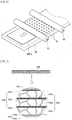
- a wireless power transmission (WPT) module including an antenna unit including an antenna for WPT, and a magnetic field unit having at least one magnetic sheet according to the present invention, which is disposed on one surface of the antenna unit and configured to improve a characteristic of the antenna for WPT and focus a magnetic flux toward the antenna for WPT.
- WPT wireless power transmission
- the antenna unit may further include at least one of an antenna for near-field communication (NFC) and an antenna for magnetic secure transmission (MST).
- NFC near-field communication
- MST magnetic secure transmission
- a near-field communication (NFC) module including an antenna unit including an antenna for NFC, and a magnetic field unit having at least one magnetic sheet according to the present invention, which is disposed on one surface of the antenna unit and configured to improve a characteristic of the antenna for NFC and focus a magnetic flux toward the antenna for NFC.
- NFC near-field communication
- thin film coating layer refers to a layer which is formed such that a composition for forming a thin film coating layer is solidified
- solidification means that the composition for forming a thin film coating layer changes from a liquid phase into a solid phase so as to sufficiently maintain a predetermined shape, and at this point, the solid phase includes a complete solid state, a partially solid state, and a state capable of having fluidity when an external force is applied.
- a magnetic sheet is improved in mechanical strength properties such as a tensile property, a bending property, and the like to have significantly superior flexibility
- degradation of physical properties, such as magnetic permeability and the like, caused by physical damage such as unintentional cracks in a magnetic body provided in the magnetic sheet can be prevented even in the process of storing, transferring, and attaching the magnetic sheet to a target object and during usage of an electronic device provided with the target object to which the magnetic sheet is attached, and the magnetic sheet can be attached to a target surface of the target object with a superior adhering force even when a stepped portion is present at the target surface, and at the same time
- the magnetic sheet can block the influence of a magnetic field on parts of a portable terminal device or a human body of a user using the portable terminal device, significantly increase transmission and reception efficiencies and distances of a data and/or wireless power signal, and maintain the above-described performance for a long period of time, such that the magnetic sheet can be widely used in various portable devices
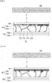
- a magnetic sheet 100 includes a magnetic layer 110a and a thin film coating layer 110b formed on at least one side of the magnetic layer, and the magnetic layer 110 is formed of a plurality of magnetic pieces 111.
- the magnetic sheet 100 may further include a protective member 140 disposed on a top of the thin film coating layer 110b and an adhesive member 130 disposed below the magnetic layer 110a, and the adhesive member 130 may include a first adhesive layer 130b and a release film 130a for protecting the first adhesive layer 130b before the magnetic sheet 100 is attached to a target object.
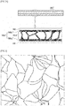
- a magnetic sheet 100' is configured such that a thin film coating layer 110b' may partially penetrate into a space between at least some of adjacent magnetic pieces to enhance a supporting force for the magnetic pieces and serve to perform buffering capable of preventing damage such as fine fragmentation, breakage, and the like of the magnetic pieces caused by collisions between the magnetic pieces when flexural strength is applied to the magnetic sheet.
- a magnetic sheet 100" is configured such that a thin film coating layer 110b" may be formed on both sides of a magnetic layer 110a", and the thin film coating layer 110b" may penetrate into an entire space between adjacent magnetic pieces.
- a magnetic body provided in the magnetic layer may be a magnetic body in which electrical resistance is low and thus a magnetic loss caused by an eddy current may occur (e.g., a magnetic body such as a Fe-Si-B-based amorphous alloy).
- the thin film coating layer penetrating into the space between the magnetic pieces serves as a dielectric to significantly increase the electric resistance of the magnetic layer such that the magnetic loss caused by the eddy current may be prevented, heat generation may be minimized, and transmission and reception efficiencies of a signal through a magnetic field may be sustained with high sensitivity.
- the magnetic body provided in the magnetic layer is a magnetic body having high electrical resistance and no magnetic loss caused by an eddy current (e.g., a ferrite-based magnetic body), unlike FIGS. 1, 2A , and 2B , it may be more advantageous to exhibit a desired magnetic property by having the thin film coating layer not penetrate between crushed pieces and thus the crushed pieces are maintained in a state of being in contact with each other.
- a cross-sectional structure of the magnetic sheet according to one embodiment of the present invention will be described below when the magnetic body is an amorphous alloy.
- the magnetic layers 110a, 110a', or 110a" is formed of the magnetic pieces 111, which are made by crushing the magnetic body, so as to improve flexibility of the magnetic sheet.
- the magnetic body may have a shape such as a ribbon sheet or a plate-shaped sheet so as to be easily implemented as a thin film.
- a thickness of a provided magnetic body should also be very thin for slimness and thinness of the magnetic sheet, and when a thickness of the magnetic sheet becomes thinner, conventional magnetic bodies provided in the magnetic sheet are very brittle and thus cracks occur in the conventional magnetic bodies even when a very weak external force is applied thereto or the conventional magnetic bodies are broken into fine pieces, such that there is a problem in that magnetic permeability after the cracks occur is significantly degraded than that before the cracks occur in the sheet phase.
- a very thin magnetic sheet has a problem of significantly degrading workability when stored, transferred, and put into a process as a part of a product after manufactured.
- a magnetic sheet is generally disposed on a surface at which an antenna and the like are formed and is generally attached to and brought into close contact with the surface at which the antenna is formed so as to further improve an antenna characteristic and prevent the magnetic sheet from escaping.
- the magnetic sheet 100 may be attached to a target surface (not shown) through the adhesive member 130, and to this end, the release film 130a protecting the first adhesive layer 130b of the adhesive member 130 is firstly removed.
- the magnetic sheet according to the present invention is provided with a magnetic body in a state of initially crushed magnetic pieces so as to significantly improve flexibility of the magnetic sheet such that a concern in which cracks may further occur in the magnetic body due to an external force can be fundamentally resolved even when a cross-sectional thickness of the magnetic sheet becomes thinner.
- the magnetic body is included in the magnetic sheet in a state of magnetic pieces, and the magnetic sheet including the magnetic body in the state of magnetic pieces has an initial physical property capable of exhibiting a superior characteristic in transmission and reception efficiencies and distances for a signal related to an initially desired function and maintains the initial physical property even in the process of manufacturing a finished product provided with the magnetic sheet and further during usage of the finished product, such that concerns in which physical property degradation caused by unintended fragmentation occurring in a magnetic sheet having a conventional non-fragmented magnetic body and significant degradation in signal transmission and reception performance due to the physical property degradation can be resolved.
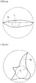
- the magnetic pieces may have amorphous shapes.
- at least one side of some of the magnetic pieces may be preferably crushed to have a curved shape instead of a straight line (see FIG. 3 ).
- collisions or friction between adjacent magnetic pieces may be reduced such that there is an advantage in that additional breakage of the magnetic pieces can be prevented.
- the number of magnetic pieces, each of which has at least one side in a curved shape may be 10% or more of the total number of magnetic pieces in the magnetic layer, preferably 30% or more thereof, more preferably 50% or more thereof, and most preferably 70% or more thereof.
- the number of the magnetic pieces, each of which has at least one side in the curved shape is less than 10% of the total number of the magnetic pieces, improvement in flexibility may be insignificant and the number of magnetic pieces that are finer than the initially provided magnetic pieces may be increased by an external impact such that there is a problem in that degradation in a physical property such as reduction in magnetic permeability may be caused.
- an average particle diameter of a single piece of the magnetic pieces may be in the range of 50 to 5000 ⁇ m.
- the average particle diameter exceeds 5,000 ⁇ m, additional breakage and fragmentation of the magnetic pieces are increased such that there is a problem in that it may be difficult for a design value of an initial physical property of the magnetic sheet to be maintained.
- the average particle diameter of the magnetic piece is less than 50 ⁇ m, it is difficult to manufacture a magnetic sheet exhibiting a physical property of a desired level because a magnetic property significantly lower than a magnetic property such as magnetic permeability of the magnetic body before being crushed is exhibited, and specifically, it is more difficult to satisfy a desired physical property relative to a thin thickness.
- the average particle diameter of the magnetic piece refers to an average volumetric diameter measured by a laser diffraction type particle size distribution meter.
- the magnetic pieces may include pieces each having a shape factor of 8.0 or less for one surface thereof according to Equation 1, preferably 6.5 or less, more preferably 4.0 or less, even more preferably 3.5 or less, even more preferably 3.0 or less, even more preferably 2.5 or less, even more preferably 2.0 or less, and most preferably 1.5 or less, in an amount of 10% or more, preferably 20% or more, more preferably 30% or more, even more preferably 40% or more, even more preferably 50% or more, even more preferably 60% or more, and most preferably 70% or more.
- shape factor diameter of circumscribed circle of piece ⁇ m diameter of inscribed circle of piece ⁇ m
- a diameter of a circumscribed circle of a magnetic piece refers to a longest distance between two points on one surface of the magnetic piece (R 1 of FIG. 4A and R 2 of FIG. 4B ), and at this point, a circle passing the two points of the magnetic piece corresponds to the circumscribed circle of the magnetic piece.
- a diameter of an inscribed circle of a magnetic piece refers to a diameter of an inscribed circle having a largest diameter among inscribed circles in contact with two or more sides which are present in any surface of the magnetic piece (r 1 of FIG. 4A and r 2 of FIG. 4B ).
- a large shape factor for one surface of the magnetic piece means that the one surface of the magnetic piece has a long shape (see FIG. 4A ) or includes a pointed portion (see FIG. 4B ), and the long shape or the pointed portion means that additional breakage or fragmentation may occur.
- a magnetic piece having a shape factor of 8.0 or less for one surface of the magnetic piece according to Equation 1 may be contained in an amount of 10% or more relative to all magnetic pieces in the magnetic layer, and more preferably, the magnetic piece having the above-described shape factor may be contained in an amount of 20% or more.
- a magnetic piece having a shape factor exceeding 8.0 When a magnetic piece having a shape factor exceeding 8.0 is contained in an amount of less than 10%, the magnetic piece is further finely fragmented and thus significant degradation of the physical properties such as magnetic permeability and the like may be caused, and a design value of the desired initial physical property may not be maintained.
- the magnetic body when a magnetic body that can be included in the magnetic layer according to the present invention is capable of exhibiting a physical property such as magnetic permeability of a magnetic sheet, which will be described below, in a fragmented state, there is no limitation on a composition, a crystal type, and a fine structure of a sintered particle and thus a magnetic body provided in a known magnetic sheet may be used.
- the magnetic body may be a soft magnetic material. Since the soft magnetic material has a very low coercive force with respect to a residual magnetic flux density and has large magnetic permeability, a blocking effect against electromagnetic fields is superior.
- the soft magnetic material may include at least one of a metallic soft magnetic material and ferrite.
- the metallic soft magnetic material may include one or more selected from the group consisting of a Ni-Co-based alloy, a Fe-Ni-based alloy, a Fe-Cr-based alloy, a Fe-Al-based alloy, a Fe-Si-based alloy, a Fe-Si-B-based alloy, and a Fe-Si-B-Cu-Nb-based alloy.
- the ferrite may include at least one selected from the group consisting of Mn-Zn-based ferrite, Ni-Zn-based ferrite, Ni-Co-based ferrite, Mg-Zn-based ferrite, Cu-Zn-based ferrite, and cobalt-substituted Y or Z hexagonal-based ferrite.
- the ferrite may include ferrite, e.g., Ni-Cu-Zn-based ferrite or Ni-Cu-Co-Zn-based ferrite, containing iron oxide and at least three oxides of metals selected from the group consisting of, nickel, zinc, copper, magnesium, and cobalt, but the present invention is not limited thereto.
- contents of nickel, zinc, copper, magnesium, and cobalt in the ferrite may be varied according to the purpose, and thus the present invention is not particularly limited thereto.
- the magnetic body included in one embodiment of the present invention may employ a thin plate magnetic material which is made of an amorphous alloy or a nanocrystalline alloy.
- a Fe-based or a Co-based amorphous alloy may be employed, and it may be preferable for the Fe-based amorphous alloy to be employed in consideration of a unit cost of production.
- a Fe-Si-B-based amorphous alloy may be employed, and in this case, it is preferable that Fe is in the range of 70 to 90 at% and the sum of Si and B is in the range of 10 to 30 at%.
- a saturation magnetic flux density becomes higher as contents of metals including Fe and the like becomes higher, but when the content of Fe is excessive, since it is difficult to form an amorphous shape, the content of Fe is preferably in the range of 70 to 90 at%.
- the sum of Si and B is in the range of 10 to 30 at%, amorphous formability of the alloy is most superior.
- corrosion resistance elements such as Cr, Co, and the like may be added in an amount of 20 at% or less, and a small amount of other metal elements may be added to impart other properties as necessary.
- the Fe-Si-B-based alloy may have a crystallization temperature of 508 °C and a Curie temperature Tc of 399 °C.
- such a crystallization temperature may be varied according to contents of Si and B, and other metal elements and contents thereof which are added in addition to ternary alloy components.
- the magnetic body included in one embodiment of the present invention may be a Fe-Si-B-Cu-Nb-based amorphous alloy.
- the copper contained in the amorphous alloy may enhance corrosion resistance of the amorphous alloy and prevent a size of a crystal from becoming larger even when the crystal is generated, and at the same time, improve magnetic properties such as magnetic permeability and the like.
- the copper is preferably contained in the amorphous alloy in the range of 0.01 to 10 at%, and when the copper is contained in an amount of less than 0.01 at%, an effect obtained from the copper may be insignificantly exhibited, and when the copper is contained in an amount of exceeding 10 at%, there is a problem in that it is difficult for the amorphous alloy to be produced.
- the niobium (Nb) contained in the amorphous alloy may improve the magnetic properties such as the magnetic permeability and the like, and is preferably contained in the amorphous alloy in the range of 0.01 to 10 at%, and when Nb is contained in an amount of less than 0.01 at%, an effect obtained from Nb may be insignificantly exhibited, and when Nb is contained in an amount of exceeding 10 at%, there is a problem in that it is difficult for the amorphous alloy to be produced.
- a thickness of the magnetic layer 110a may be a thickness of the magnetic sheet which is the origin of the magnetic pieces, and preferably, a thickness of a single layer of the magnetic layer may be in the range of 1 ⁇ m to 300 ⁇ m but is not limited thereto.
- a shape of the magnetic layer may have a shape according to application of the magnetic sheet, e.g., when used for near-field communication (NFC), a shape of the magnetic layer may have a polygonal shape such as a pentagonal shape, a circular shape, an elliptical shape, or a mixed shape in which a curved line and a straight line are partially mixed in addition to a quadrangular shape having a rectangular shape and a square shape so as to correspond to an antenna form for NFC.
- a size of the magnetic sheet (or the magnetic layer) is preferably formed to be about 1 to 2 mm wider than an antenna size of a corresponding module.
- the thin film coating layer 110b formed on at least one surface of the above-described magnetic layer 110a will be described.
- the thin film coating layer 110b serves to form the magnetic pieces which are crushable and separable as a layer by fixing and supporting each of the magnetic pieces, thereby maintaining the magnetic layer in a sheet shape and at the same time, serves to buffer an external force applied to the magnetic pieces and to prevent oxidation of the magnetic body due to moisture infiltration.
- the thin film coating layer 110b may be easily attached to the magnetic pieces, may have superior sheet shape retentivity as a coating layer, may not have a significantly low bending property so as to be easily broken by an external force or reduce flexibility of the magnetic layer, may have superior film properties to be implemented as a thin film, and may be used as a preferable thin film coating layer without limitation as long as it is a slightly tacky material at room temperature and thus workability is not deteriorated.
- the thin film coating layer 110b may be formed by solidifying a composition for forming a thin film coating layer containing at least one of a natural polymer compound and a synthetic polymer compound.
- a method for solidifying the composition for forming a thin film coating layer is not particularly limited. For example, any one of solidification by drying or curing through solvent volatilization, solidification by curing through a chemical reaction by heat, light, moisture, or the like, and solidification by cooling after heat melting such as a hot melt type may be used as a solidification reaction without limitation.
- the natural polymer compound may include one or more of a protein-based polymer compound such as glue, gelatin, or the like, a carbohydratebased polymer compound such as starch, cellulose, a cellulose derivative, complex polysaccharides, or the like, and a natural rubber-based compound such as latex or the like.
- a protein-based polymer compound such as glue, gelatin, or the like
- a carbohydratebased polymer compound such as starch, cellulose, a cellulose derivative, complex polysaccharides, or the like
- a natural rubber-based compound such as latex or the like.
- the synthetic polymer compound may include one or more of a thermoplastic polymer compound, a thermosetting polymer compound, and a rubber-based compound.
- the thermoplastic polymer compound may include one or more of polyethylene, polypropylene, polystyrene, polyvinyl chloride, a polyacrylonitrile resin, acrylonitrile-butadiene-styrene (ABS), styrene-acrylonitrile (SAN), an acrylic-based resin, a (meth)acrylic-based resin, polyamide, thermoplastic polyester (e.g., polyethylene terephthalate (PET), polybutylene terephthalate (PBT), and the like), polycarbonate, a polyphenylene sulfide resin, polyamideimide, polyvinyl butyral, polyvinyl formal, polyhydroxy polyether, polyether, polyphthalamide, a fluorinebased resin (e.g., polytetrafluoroethylene (PTFE) and polychlorotrifluoroethylene (PCTFE)), a phenoxy resin, a polyurethane resin, a nitrile butadiene resin, and the like
- thermosetting polymer may include one or more of a phenolicbased resin (PE), a urea-based resin (UF), a melamine-based resin (MF), an unsaturated polyester-based resin (UP), an epoxy resin, and the like.
- the rubber-based compound may include one or more of styrene-butadiene rubber (SBR), polybutadiene rubber (BR), acrylonitrile-butadiene rubber (NBR), polyisobutylene (PIB) rubber, acrylic rubber, fluorine rubber, silicone rubber, chloroprene, and the like.
- the thin film coating layer 110b is formed by solidifying the rubber-based compound to prevent unintended fine fragmentation of the magnetic body through enhancement in buffering of a thin film coating layer and to further improve flexibility of the magnetic sheet, and the rubber-based compound is ethylene propylene diene monomer (EPDM) rubber.
- EPDM ethylene propylene diene monomer
- a copolymerization molar ratio of each of the monomers may be varied according to the purpose, so that the present invention is not particularly limited to the aforementioned.
- composition for forming a thin film coating layer employed to form the thin film coating layer 110b is solidified through a curing reaction
- a curable component capable of curing the above-described polymers may further be included, and in some cases, a solvent and a curing accelerator may further be included.
- the curable component when it is a known component, it may be used without particular limitation, and as a non-limiting example, an amine compound, a phenolic resin, an acid anhydride, an imidazole compound, a polyamine compound, a hydrazide compound, a dicyandiamide compound, and the like may be used alone or in combination of two or more thereof.
- Aromatic amine compound curable components may include m-xylenediamine, m-phenylenediamine, diaminodiphenylmethane, diaminodiphenylsulfone, diaminodiacyldiphenylmethane, diaminodiphenyl ether, 1,3-bis(4-aminophenoxy)benzene, 2,2'-bis[4-(4-aminophenoxy)phenyl]propane, bis[4(4-aminophenoxy)phenyl]sulfone, 4,4'-bis(4-aminophenoxy)biphenyl, 1,4-Bis(4-aminophenoxy)benzene, and the like, and these curable components may be used alone or in combination thereof.
- phenolic resin curable components may include a phenol novolac resin, a cresol novolac resin, a bisphenol-A novolac resin, a phenol aralkyl resin, a poly(p-vinylphenol) t-butylphenol novolac resin, a naphthol novolac resin, and the like, and these curable components may be used alone or in combination thereof.
- a curable component content is preferably in the range of 20 to 60 parts by weight per 100 parts by weight of the above-described polymer, and when the curable component content is less than 10 parts by weight, a curing reaction is insignificant and thus a bending or tensile property of a desired level may not be exhibited, and when the curable component content exceeds 60 parts by weight, reactivity of the curable component with the polymer becomes higher and thus physical properties such as handleability and long-term storage may be deteriorated.
- curing accelerator may be determined according to specific types of the selected polymer and curable component and thus it is not particularly limited in the present invention, and as a non-limiting example, curing accelerators may include amine-based, imidazole-based, phosphorus-based, boron-based, and phosphorus-boron-based curing accelerators and these curing accelerators may be used alone or in combination thereof.
- a curing accelerator content is preferably in the range of about 0.1 to 10 parts by weight, and more preferably in the range of 0.5 to 5 parts by weight based on 100 parts by weight of the polymer.
- the solvent may be used without limitation in a case in which the solvent is usually used in a coating composition, and as a non-limiting example, the solvent may be a type of ketone such as acetone, methyl ethyl ketone (MEK), methyl isobutyl ketone (MIBK), cyclohexanone, and the like, or a type of ether such as methyl cellosolve, ethylene glycol dibutyl ether, butyl cellosolve acetate, and the like.
- An amount of the solvent used is not particularly limited but is preferably in the range of 10 to 500 parts by weight based on 100 parts by weight of the polymer.
- one or two or more of various additives including a pH adjuster, an ion capturing agent, a viscosity adjusting agent, a thixotropic agent, an antioxidant, a heat stabilizer, a light stabilizer, an ultraviolet absorber, a colorant, a dehydrating agent, a flame retardant, an antistatic agent, an antifungal agent, an antiseptic agent, and the like may be added to the composition for forming a thin film coating layer as necessary.
- various additives including a pH adjuster, an ion capturing agent, a viscosity adjusting agent, a thixotropic agent, an antioxidant, a heat stabilizer, a light stabilizer, an ultraviolet absorber, a colorant, a dehydrating agent, a flame retardant, an antistatic agent, an antifungal agent, an antiseptic agent, and the like may be added to the composition for forming a thin film coating layer as necessary.
- the pH adjuster is not particularly limited, and examples thereof may include acidic fillers such as silica and the like, or alkaline fillers such as calcium carbonate and the like. These pH adjusters may be used alone or in combination of two or more thereof.
- the ion capturing agent is not particularly limited as long as it can reduce an amount of ionic impurities, and examples thereof may include aluminosilicate, hydrated titanium oxide, hydrated bismuth oxide, zirconium phosphate, titanium phosphate, hydrotalcite, ammonium molybdophosphate, hexacyano zinc, an organic ion exchange resin, and the like, these ion capturing agents may be used alone or in combination of two or more thereof. Other known additives may be used, and thus detailed descriptions of specific types thereof will be omitted.
- the thickness of the thin film coating layer 110b is preferably implemented within 10 ⁇ m, and in terms of thinness, the thickness is preferably implemented with 5 ⁇ m or less.
- the thickness is implemented with less than 5 ⁇ m, the chipping off and floating of the magnetic pieces may not be prevented and thus there may be a problem in that the thin film coating layer is easily torn due to weak mechanical strength or is torn or damaged due to the magnetic pieces.
- the protective member 140 may be disposed on the top of the thin film coating layer 110b, and the adhesive member 130 having the release film 130a and the first adhesive layer 130b formed on one surface of the release film 130a may further be included below the magnetic layer 110a.
- the protective member 140 may primarily prevent an external force from being directly applied to the magnetic body in the process of crushing the magnetic sheet and prevent scattering of a magnetic powder generated in the crushing process, thereby helping to maintain a comfortable workplace environment. Further, in the process of attaching the magnetic sheet to a substrate having an antenna, the protective member 140 serves to protect the magnetic sheet from heat, a pressure, and the like which are applied to cure an adhesive.
- the protective member 140 may be a protective film which is generally provided in the magnetic sheet, and any protective member may be used without limitation as long as it is made of a material securing heat resistance sufficient to withstand the heat or external force applied in the process of crushing or attaching the magnetic sheet, and mechanical strength and chemical resistance sufficient to protect the magnetic layer 110a from externally applied physical and chemical stimuli.
- protective films may include a polyethylene film, a polypropylene film, a polyimide film, a crosslinked polypropylene film, a nylon film, a polyurethane-based resin film, an acetate film, a polybenzimidazole film, a polyimideamide film, a polyetherimide film, a polyphenylene sulfide (PPS) film, a PET film, a polytrimethylene terephthalate (PTT) and PBT film, a polyvinylidene fluoride (PVDF) film, a PTFE and PCTFE film, a polyethylene tetrafluoroethylene (ETFE) film, and the like, and these protective films may be used alone or in combination thereof.
- the protective member 140 having a thickness in the range of 1 to 100 ⁇ m, preferably in the range of 10 to 30 ⁇ m, may be used but is not limited thereto.
- the protective member 140 may be directly attached to the thin film coating layer 110b without a separate adhesive member or may be attached by interposing a separate adhesive member. However, for the purpose of thinness of the magnetic sheet, the protective member 140 is preferably directly attached to the thin film coating layer 110b without interposing an adhesive member.
- the adhesive member 130 serves to attach the magnetic sheet 100a to an antenna or a substrate provided with the antenna.
- the adhesive member 130 may include the first adhesive layer 130b for attaching the magnetic sheet 100 to a target surface and may further include the release film 130a for protecting the first adhesive layer 130b.
- a generally known release film may be used as the release film 130a without particular limitation as long as it can be easily removed from the first adhesive layer 130b, and the release film 130a may be removed from the magnetic sheet 100 before the magnetic sheet 100 is attached to a target surface.
- the first adhesive layer 130b may be formed by applying a composition for forming an adhesive layer to a lower portion of the magnetic layer 110a or may be provided such that the first adhesive layer 130b formed by applying the composition for forming an adhesive layer on the release film 130a is attached to the magnetic layer 110a or 110a'.
- the first adhesive layer 130b may be a double-sided adhesive layer in which the composition for forming an adhesive layer is coated on both sides of a support film to reinforce mechanical strength.
- the above-described magnetic sheet may be manufactured by a first manufacturing method and a second manufacturing method which will be described below but the present invention is not limited thereto, and the first manufacturing method will be described first.
- the magnetic sheet may be manufactured by the first manufacturing method according to the present invention including an operation (1) of forming a thin film coating layer on at least one surface of the magnetic sheet, and an operation (2) of crushing the magnetic sheet having the thin film coating layer formed thereon, and first, in the operation (1) according to one embodiment of the present invention, the forming of the thin film coating layer on at least one surface of the magnetic sheet is performed.
- the magnetic sheet may be manufactured by a known manufacturing method for each type of magnetic material or may employ a commercially available magnetic sheet.
- the magnetic material is a Ni-Zn-Cu-Co-based ferrite sheet
- the corresponding ferrite is manufactured as follows. First, a raw material mixture is obtained by mixing nickel oxide, zinc oxide, copper oxide, cobalt oxide, and iron trioxide in a predetermined composition ratio. At this point, the raw material mixture may be mixed through dry or wet mixing, and a particle diameter of a mixed raw material is preferably in the range of 0.05 to 5 ⁇ m.
- Components such as the nickel oxide and the zinc oxide included in the raw material mixture may be respectively included in the raw material or may be included in the raw material in the form of a composite oxide containing the respective components, and the cobalt oxide may also be included in the raw material in the form of cobalt ferrite or cobalt tetraoxide.
- plasticization is performed on the raw material mixture to obtain a plasticized material.
- Plasticization is performed to promote pyrolysis of the raw material, homogenization of the components, generation of ferrite, disappearance of ultrafine powder by sintering, and particle growth to an appropriate particle size, thereby converting the raw material mixture into a form suitable for the subsequent process.
- Such plasticization may be preferably performed at a temperature in the range of 800 to 1100 °C for about 1 to 3 hours.
- Plasticization may be performed under an air atmosphere or an atmosphere in which an oxygen partial pressure is higher than that of the air atmosphere.
- the obtained plasticized material is crushed to obtain a crushed material.
- Crushing is performed to break up the agglomeration of the plasticized material to obtain a powder having an appropriate degree of a sintering property.
- wet crushing may be performed using a ball mill, an attritor, or the like after coarse crushing is performed. Wet crushing may be performed until an average particle diameter of the crushed material is preferably in the range of 0.5 to 2 ⁇ m.
- the crushed material is slurried together with additives such as a solvent, a binder, a dispersant, a plasticizer to manufacture a paste.
- additives such as a solvent, a binder, a dispersant, a plasticizer to manufacture a paste.
- a ferrite sheet having a thickness in the range of 50 to 350 ⁇ m may be formed using the paste.
- binder removal and calcination may be performed to manufacture the ferrite sheet. Calcination may preferably be performed at a temperature in the range of 900 to 1300 °C for about 2 to 5 hours, and at this point, calcination may be performed under an air atmosphere or an atmosphere in which an oxygen partial pressure is higher than that of the air atmosphere.
- the ferrite sheet may be manufactured by a known method such as powder compression molding, injection molding, calendering, extruding, or the like after a ferrite powder and a binder resin are mixed.
- an operation 1-1) of applying the composition for forming a thin film coating layer on at least one surface of the magnetic sheet, and an operation 1-2) of partially solidifying or solidifying the applied composition for forming a thin film coating layer may preferably be performed.
- the composition for forming a thin film coating layer may include the above-described polymer and the above-described curable components and may further include a solvent in the case of a solvent curing type.
- the composition for forming a thin film coating layer may have a viscosity in the range of 10 to 3000 cps so as to uniformly apply the thin film with a very thin thickness, but the viscosity may be varied according to a specific method of applying the composition for forming a thin film coating layer on the magnetic sheet, and as one example, the viscosity may be in the range of 1000 to 30000 cps in the case of silk screening.
- any method of applying the composition for forming a thin film coating layer on the magnetic sheet may be used without limitation as long as it can apply a known coating composition on a surface, and as a non-limiting example, the composition may be applied on the magnetic sheet by a method such as blade coating, flow coating, casting, printing, transferring, brushing, dipping, or spraying.
- the adhesive member 130 may be attached, before the operation 1-1) is performed, to one surface of the magnetic sheet 100 on which the composition for forming a thin film coating layer is not applied.
- the timing at which the first adhesive member 130 is attached is not necessarily limited to the aforementioned, and the adhesive member 130 may be attached between the operation 1-1) and the operation 1-2), which will be described below, or may be attached after an operation (2) of crushing.
- the operation 1-2) may be performed to solidify entirely or partially the composition for forming a thin film coating layer, which is applied on the magnetic sheet.
- a selected solidification degree for the composition for forming a thin film coating layer may be varied according to a specific embodiment, and for example, in a method of manufacturing a magnetic sheet having a plurality of magnetic layers without using a separate adhesive layer for attaching the plurality of magnetic layers, a thin film coating layer may be maintained in a semi-solidified state so as to substitute the thin film coating layer with an adhesive layer.
- a completely solidified thin film coating layer has almost no tackiness for workability at room temperature and has no adhesiveness, it is impossible to attach the completely solidified thin film coating layer to another magnetic layer without an adhesive, but there is an advantage in that the semi-solidified thin film coating layer according to the composition may attach two independently manufactured magnetic layers to each other without a separate adhesive through complete solidification after the semi-solidified thin film coating layer is attached to the other magnetic layer.
- a composition for forming a thin film coating layer which is capable of having mechanical strength and a bending property which prevent the semi-solidified thin film coating layer from being tearing or damaged by magnetic pieces generated in the operation (2) of crushing, may preferably be implemented in a semi-solidified state.
- a type of solidification (or curing) performed in the operation 1-2) may be determined according to a type of polymer included in the composition for forming a thin film coating layer and specific types of curable components which are further provided according to a type of selected polymer, and when solidification is realized by curing through a chemical reaction, e.g., solidification is realized by thermal curing, curing may be performed at a temperature in the range of 50 to 200 °C for 1 second to 10 minutes, and for specific curing, a known method may be employed and thus the present invention is not particularly limited thereto.
- the composition for forming a thin film coating layer may be cured by passing through a separate heat source, and at this point, a constant pressure may additionally be applied to the composition, and as an example in which heat and a pressure can simultaneously be applied, a magnetic sheet on which the composition for forming a thin film coating layer is applied passes through a hot roller, which is heated at a desired temperature, such that the composition for forming a thin film coating layer may be cured.
- photocuring may be performed under the action of actinic rays of preferable high-energy radiation, i.e., UV radiation or sunlight and preferably having wavelengths in the range of 200 nm to 750 nm.
- a radiation source or a UV light source may include a medium or high pressure mercury vapor or the like, and the mercury vapor may be modified by injection with another element such as gallium or iron.
- a laser, a pulsed lamp (called a UV flash lamp), a halogen lamp or an excimer radiation means may also be used.
- the radiation means may be installed at a fixed position and the magnetic sheet, which will be irradiated, may be moved to pass through the radiation source by a mechanical device, and alternatively, the radiation means may be movable and the magnetic sheet, which will be irradiated, is not displaced during curing.
- a sufficient radiation dose is in the range of 80 mJ/cm 2 to 5000 mJ/cm 2 and a radiation intensity is in the range of 80 mW/cm 2 to 3000 mW/cm 2 .
- the radiation may also optionally be performed except for oxygen under an insoluble gas atmosphere or an oxygen-depleted atmosphere.
- the suitable insoluble gas is nitrogen, carbon dioxide, an inert gas, or a combustion gas.
- the irradiation may be performed by coating a dry layer having a medium which transmits radiation.
- the magnetic sheet 100 further include the protective member 140 on the thin film coating layer 110b without a separate adhesive
- a protective member is disposed on the composition for forming a thin film coating layer between the operation 1-1) and the operation 1-2) and then the operation 1-2) of solidification or partial solidification is performed.
- a known method of crushing a magnetic body may be employed as the method of crushing the magnetic sheet without limitation.
- a stacked structure in which an adhesive member, a magnetic sheet, a thin film coating layer, and a protective member are sequentially stacked in the order thereof may pass through a crushing device and thus the magnetic sheet may be broken into amorphous magnetic pieces, and thereafter, a pressure may be applied to planarize a magnetic layer and allow the thin film coating layer to firmly fix the magnetic pieces.
- the stacked structure may be crushed in a state of having only the thin film coating layer without the protective member, and even when the stacked structure has the protective member when crushed, a temporary protective member such as paper without having an adhesive layer may be disposed on the magnetic sheet having the thin film coating layer formed thereon and then may be removed after the stacked structure is crushed.
- the applied pressure may be varied according to the purpose, and as an example, when a stacked structure includes a thin film coating layer in a semi-solidified state, the applied pressure may be adjusted to infiltrate a portion of the thin film coating layer into a space between the magnetic pieces and the number of times the pressure is applied may be increased.
- the thin film coating layer infiltrates into the space between the magnetic pieces as described above, the thin film coating layer may firmly fix and support the magnetic pieces and at the same time, buffer the magnetic pieces, thereby preventing additional damage, crushing, and fine fragmentation of the magnetic pieces caused by an external force, such that degradation of physical properties and moisture infiltration may be blocked to prevent oxidation of the magnetic body.
- the applying of the pressure to the stacked structure may be performed by applying a pressure to the stacked structure together with the crushing in the crushing device or may be further performed by a separate pressure applying process after the stacked structure is crushed.
- the magnetic sheet 100' may be manufactured such that a stacked structure 100'a, in which a magnetic body made of an amorphous alloy is stacked, is crushed and pressurized by passing through a crushing device having a plurality of first rollers 11 and 12 with uneven portions 11a and 12a and second rollers 21 and 22 corresponding to the plurality of first rollers 11 and 12, and then a stacked structure 100'b is further pressurized by a third roller 13 and a fourth roller 23 corresponding to the third roller 13.
- infiltration of the thin film coating layer into the space between the crushed magnetic pieces may be controlled according to a degree of pressurization.
- a magnetic sheet 101 may be manufactured such that a stacked structure 101a including a ferrite magnetic body is crushed and pressurized by passing through the same crushing device, and then a stacked structure 101b is further pressurized by the third roller 13 and the fourth roller 23 corresponding to the third roller 13, thereby allowing the magnetic sheet 101 to have an appropriate particle size distribution.
- it may be important to control the degree of pressurization such that the space between the crushed magnetic pieces is minimized and the thin film coating layer is prevented from infiltrating into the space.
- the stacked structure 100'a including a magnetic sheet is put into a crushing device which is provided with a support plate 30 having a plurality of metal balls 31 mounted on one surface thereof and rollers 41 and 42 disposed on the support plate 30 and configured to move a target object which will be crushed, and a pressure is applied to the stacked structure 100'a through the plurality of metal balls 31, such that the magnetic sheet may be crushed.
- Each of the plurality of metal balls 31 may be in a spherical shape but is not limited thereto, and a shape of each of the plurality of metal balls 31 may be a triangle, a polygon, an ellipse, or the like, and a shape of a ball provided at each roller may be one shape or a mixture of various shapes.
- a magnetic sheet may be manufactured by the second manufacturing method according to the present invention including an operation (1') of crushing a magnetic body and manufacturing a magnetic layer formed of magnetic pieces, and an operation (2') of forming a thin film coating layer on the magnetic layer.
- the operations (1') and (2') are the same as the operations (2) and (1) of the above-described first manufacturing method, and thus overlapping descriptions will be omitted.
- a temporary protective member may further be provided on one side of the magnetic layer in the operation (1') to pass through the crushing device.
- the temporary protective member has advantages of preventing scattering and a loss of the crushed magnetic body to make a comfortable workplace environment and preventing an increase in material cost due to the loss of the magnetic body.
- the temporary protective member may have an adhesive layer on one surface thereof to be temporarily adhered to the magnetic body or may be physically placed on the magnetic body without being temporarily adhered to the magnetic body and may pass through the crushing device.
- the temporary protective member may be a conventional PET film or paper, and there is no particular limitation on a material.
- the above-described first manufacturing method is easily implemented to prevent the infiltration of the thin film coating layer into the space between the magnetic pieces rather than the second manufacturing method, so that the first manufacturing method may be more suitable for an embodiment in which a magnetic layer is formed of magnetic pieces of a magnetic body such as ferrite having high specific resistance and a magnetic property which is prone to deteriorating when the thin film coating layer infiltrates into the space between the magnetic pieces.
- the first manufacturing method may be suitable for a case in which a magnetic sheet is provided with a magnetic body including at least one selected from the group consisting of Mn-Zn-based ferrite, Ni-Zn-based ferrite, Ni-Co-based ferrite, Mg-Zn-based ferrite, Cu-Zn-based ferrite, and cobalt-substituted Y or Z hexagonal ferrite.
- the second manufacturing method is more advantageous to implement the thin film coating layers 110b' or 110b" to partially or entirely infiltrate into the space between the magnetic pieces rather than the first manufacturing method, so that the second manufacturing method is more suitable for an embodiment in which a magnetic layer is formed of a magnetic body in which a magnetic loss may be caused by an eddy current due to low electrical resistance (e.g., a magnetic body such as a Fe-Si-B-based amorphous alloy).
- a magnetic layer is formed of a magnetic body in which a magnetic loss may be caused by an eddy current due to low electrical resistance (e.g., a magnetic body such as a Fe-Si-B-based amorphous alloy).
- a magnetic sheet 200 may include a plurality of magnetic layers 210a 1 , 210a 2 , and 210a 3 , and thin film coating layers 210b 2 and 210b 3 may be stacked between the adjacent magnetic layers 210a 1 and 210a 2 and the adjacent magnetic layers 210a 2 and 210a 3 .
- thin film coating layers 210b 2 and 210b 3 may be stacked between the adjacent magnetic layers 210a 1 and 210a 2 and the adjacent magnetic layers 210a 2 and 210a 3 .
- a portion of the second thin film coating layer 210b 2 may infiltrate into a lower portion of a space between magnetic pieces forming the first magnetic layer 210a 1 and an upper portion of a space between magnetic pieces forming the second magnetic layer 210a 2
- a portion of the third thin film coating layer 210b 3 may infiltrate into a lower portion of a space between magnetic pieces forming the second magnetic layer 210a 2 and an upper portion of a space between magnetic pieces forming the third magnetic layer 210a 3 , such that effects of supporting the magnetic pieces, fixing the magnetic pieces, preventing additional damage, crushing, and fine fragmentation of the magnetic pieces due to an external force, and blocking moisture infiltration may be further improved.
- the magnetic sheet of FIG. 1 having only the single magnetic layer may be limited in some cases to exhibit a physical property suitable for some applications. That is, in order to improve the magnetic properties of the magnetic sheet, a magnetic body having a superior magnetic property such as magnetic permeability may be selected, or in the case of a magnetic body having relatively low magnetic permeability, a magnetic layer may be implemented to prevent easy magnetic saturation thereof by increasing a thickness of the magnetic layer. However, in order to increase the thickness of the magnetic layer, a thickness of a single-layered magnetic sheet in which the magnetic layer is formed should be increased to a predetermined level or more.
- a plurality of magnetic layers are provided to increase an overall thickness of a magnetic layer in a magnetic sheet such that a magnetic saturation capacity of the magnetic layer may increase, and the magnetic sheet having the stacked magnetic layers further improves an antenna characteristic for a desired application such that signal transmission and reception efficiencies and distances may be significantly improved.
- the number of magnetic layers is preferably 2 to 12, and more preferably 3 to 10.
- the number of stacked magnetic layers exceeds 12
- improvement in antenna a characteristic for a desired application may be insignificant
- an improvement range in antenna a characteristic for a desired application may be insignificant in comparison with a single magnetic layer such that the antenna characteristic may not be improved to a desired level.
- a protective member 240 included in one embodiment of the present invention may be attached to a first thin film coating layer 210b 1 without a separate adhesive, and alternatively, unlike shown in FIG. 7 , the protective member 240 may be attached on the first thin film coating layer 210b 1 through a separate adhesive layer (not shown) or on the first magnetic layer 210a 1 by omitting the first thin film coating layer 210b 1 .
- an adhesive member 230 may be provided below the third magnetic layer 210a 3 to be attached on a target surface to which the magnetic sheet will be attached. At this point, the adhesive member 230 may be attached to a lower portion of the third magnetic layer 210a 3 through a separate adhesive layer (not shown). Alternatively, unlike shown in FIG. 7 , unlike shown in FIG.
- the adhesive member 230 may be attached to a lower portion of the fourth thin film coating layer (not shown) through an adhesive layer (not shown) or may be directly attached to the lower portion thereof without the adhesive layer.
- a manufacturing method of the magnetic sheet of FIG. 7 having the plurality of magnetic layers is specifically similar to the above-described manufacturing method of the magnetic sheet having the single magnetic layer, and as one example, the magnetic sheet of FIG. 7 may be manufactured by the manufacturing method including manufacturing a stacked structure having a plurality of magnetic layers by interposing a thin film coating layer between adjacent magnetic layers, and crushing the stacked structure, and specifically, the magnetic sheet of FIG.
- the manufacturing method including manufacturing the stacked structure by alternately stacking a magnetic layer and a composition for forming a thin film coating layer in a manner of applying the composition for forming a thin film coating layer on a first magnetic layer and disposing a second magnetic layer on the composition for forming a thin film coating layer and curing the stacked magnetic layers and compositions, and crushing the stacked structure.
- the magnetic sheet having a plurality of magnetic layers may be manufactured by preparing the plurality of magnetic layers, each of which has a semi-cured thin film coating layer on one surface thereof, formed of magnetic pieces, stacking the plurality of magnetic layers to interpose the semi-cured thin film coating layers between the plurality of magnetic layers, and completely solidifying the semi-cured thin film coating layers.
- the magnetic sheet having a plurality of magnetic layers may be manufactured by preparing the plurality of magnetic layers, each of which has a semi-solidified thin film coating layer on one surface thereof, stacking the plurality of magnetic layers to interpose the semi-solidified thin film coating layers between the plurality of magnetic layers to thereby manufacture a stacked structure, and completely solidifying the semi-solidified thin film coating layers to crush the stacked structure or crushing the stacked structure to completely solidify the semi-solidified thin film coating layers.
- compositions, fine structures, and/or physical properties of magnetic bodies included in the plurality of magnetic layers 210a 1 , 210a 2 , and 210a 3 may be the same or be different from each other. Further, it may be configured such that thicknesses of the plurality of magnetic layers may be the same, may be partially different from each other, or may be entirely different therefrom according to the purpose, and thus the thicknesses are not particularly limited in the present invention.
- each of the magnetic sheets 100, 100', 100", and 200 of the various embodiments of the present invention may include at least one functional layer (not shown) for blocking electromagnetic waves and/or for dissipating heat on at least one surface of each of the magnetic sheets 100, 100', 100", and 200.
- the magnetic sheet having the functional layer may prevent a significant increase in frequency variation of an antenna combined with the magnetic sheet due to electromagnetic waves such as power supply noise to thereby reduce a defect rate of the antenna, and when a portable device to which the magnetic sheet is applied generates heat, the magnetic sheet may easily dissipate the heat to prevent degradation in durability of parts and in functions caused by heat generation and user discomfort caused by heat transfer.
- the functional layer provided at a top and/or a bottom of the magnetic sheet is a functional layer having a heat dissipation function, transversal thermal conductivity of the magnetic sheet may be improved.
- a functional layer such as an electromagnetic wave blocking layer, a heat dissipation layer, and/or a composite layer in which the electromagnetic wave blocking layer and the heat dissipation layer are stacked or in which the electromagnetic wave blocking layer and the heat dissipation layer are combined as a single layer may be provided at a top of the protective member 140 and/or a bottom of the adhesive member 130 of the magnetic sheet 100.
- a metal foil such as copper, aluminum, or the like, which has superior thermal conductivity and superior electrical conductivity, may be attached to the top of the protective member 140 through an adhesive or a double-sided tape.
- the adhesive may be a known adhesive, and as a non-limiting example, an acrylic-based adhesive, a urethane-based adhesive, an epoxy-based adhesive, and the like may be used.
- the adhesive may have heat radiation performance, and to this end, a known filler such as nickel, silver, a carbon material, or the like may be mixed with the adhesive, and the content of the filler may be a content of a filler in a known heat dissipation adhesive and thus the content of the filler is not particularly limited in the present invention.
- a known filler such as nickel, silver, a carbon material, or the like
- the content of the filler may be a content of a filler in a known heat dissipation adhesive and thus the content of the filler is not particularly limited in the present invention.
- a thickness of the functional layer may be in the range of 5 to 100 ⁇ m, and more preferably in the range of 10 to 20 ⁇ m in order to reduce the thickness of the magnetic sheet.
- the magnetic sheet 100, 100', 100", or 200 may be implemented as a composite magnetic unit which is combined with another magnetic sheet having a different magnetic property at a predetermined frequency and is capable of simultaneously improving characteristics of antennas using different frequency bands, and at this point, the magnetic sheet 100, 100', 100", or 200 and the other magnetic sheet may be disposed in a stacked structure or the magnetic sheet 100, 100', 100", or 200 may be disposed and inserted into the other magnetic sheet, and thus a specific arrangement relationship is not limited in the present invention.
- the magnetic sheet may be used for the purpose of blocking a magnetic field at a specific frequency, and the same magnetic sheet may be used for the purpose of absorbing electromagnetic waves in other specific frequency bands.
- the above-described magnetic sheet 100, 100', 100", or 200 may be attached on at least one surface of an antenna core as a magnetic field unit 1000 including at least one magnetic sheet and may be implemented as a low-frequency antenna, and as shown in FIG. 8A , the low-frequency antenna includes an antenna core 1100, the magnetic field unit 1000 attached to both sides of the antenna core 1100, and a coil 1400 wound on an outer surface of each of the antenna core 1100 and the magnetic field unit 1000.
- the antenna core 1100 may be a magnetic body, e.g., Ni-Zn-based ferrite and may have a long bar shape, and the long bar shaped antenna core may be easily segmented into lumps due to high brittleness of ferrite, so that there is problem in that an initially designed physical property such as magnetic permeability may not be satisfied.
- the magnetic field unit attached to at least one surface of the antenna core has an advantage of continuously exhibiting a function as the low-frequency antenna through complementation of the physical property, and since the magnetic sheet provided in the magnetic field unit is superior in terms of flexibility and buffering, additional fine fragmentation of magnetic pieces provided in the magnetic sheet is prevented even when an external force is applied, such that complementation of the magnetic property of the antenna core may be sustained through the magnetic field unit for a long period of time.
- the above-described magnetic sheet according to one embodiment of the present invention may be used as a core for implementing a low-frequency antenna, and as shown in FIG. 8B , the low-frequency antenna may be implemented by including a magnetic layer 1010a configured with three layers, a thin film coating layer 1010b interposed between the three layers of the magnetic layer 1010a, a core portion formed of a magnetic sheet 1000' implemented with protective members 1041 and 1042 on both sides of the magnetic layer 1010a, and a coil 1400' wound on an outer surface of the core portion, and the low-frequency antenna shown in FIG. 8B may be more advantageous for exhibiting a very superior characteristic in a low-frequency region including an operating frequency of 22 kHz.
- the above-described magnetic sheet 100, 100', 100", or 200 may be implemented as a WPT module by being combined with an antenna for WPT as the magnetic field unit 1000 including at least one magnetic sheet.
- the magnetic field unit 1000 may be disposed on one surface of an antenna unit 1500 including an antenna 1530 for WPT formed on a circuit board 1510 to improve a characteristic of the antenna 1530 for WPT and focus a magnetic flux toward the antenna 1530 for WPT.
- the magnetic field unit 1000 may be attached to the antenna unit 1500 through an adhesive member, which may be provided on one surface of the magnetic sheet, or through a separate adhesive member (not shown).
- the antenna unit included in one embodiment of the present invention may further include one or more of an antenna for NFC and an antenna for magnetic secure transmission (MST).
- an antenna 1540 for MST may be disposed outside the antenna 1530 for WPT and an antenna 1550 for NFC may be disposed outside the antenna 1540 for MST to form the antenna unit 1500.
- the antenna for WPT provided in the antenna unit included in one embodiment of the present invention may include one or more of a magnetic resonance type antenna for WPT having an operating frequency in a frequency band including a frequency of 6.78 MHz and a magnetic induction type antenna for WPT having an operating frequency in a frequency band including a frequency of 100 kHz.
- the antenna unit 1500 may include a magnetic induction type antenna 1530 for WPT disposed at an innermost side of the antenna unit 1500 and having an operating frequency in a frequency band including a frequency of 100 kHz and a magnetic resonance type antenna 1520 for WPT disposed at an outermost side of the antenna unit 1500 and having an operating frequency in a frequency band including a frequency of 6.78 MHz.
- the above-described magnetic sheet 100, 100', 100", or 200 may be implemented as an NFC module by being combined with an antenna for NFC as the magnetic field unit 1000 including at least one magnetic sheet.
- the magnetic field unit 1000 may be disposed on the antenna unit 1500 including an antenna 1551 for NFC formed on the circuit board 1510 to improve a characteristic of the antenna 1551 for NFC and focus a magnetic flux toward the antenna 1551 for NFC.
- the above-described WPT module or the above-described NFC module according to the present invention may be a transmission module for transmitting a radio signal to an electronic device or a reception module for receiving a radio signal from the transmission module.
- each of the antennas 1520, 1530, 1540, 1550, and 1551 provided in the antenna unit 1500 included in the WPT module or the NFC module may be an antenna coil in which a coil is wound to have a predetermined inner diameter or an antenna pattern which is printed on a substrate, and a specific shape, structure, size, and material of the antenna are not particularly limited in the present invention.
- the above-described NFC module and/or the above-described wireless charging module may be provided in a portable device as an NFC reception module for receiving transmitted data or a wireless power reception module for receiving transmitted wireless power and data, and thus WPT efficiency, data reception efficiency, and a charging distance or a data reception distance may be significantly improved.
- a Fe 91.6 Si 2 B 6 Co 0.2 Ni 0.2 amorphous alloy ribbon was manufactured by rapid solidification (RSP) using melt spinning, a ribbon sheet cut into a sheet shape and having a thickness of 24 ⁇ m was subjected to non-magnetic field heat treatment at a temperature of 460 °C for 1 hour under an air atmosphere, and thus the ribbon sheet having a magnetic body was manufactured.
- RSP rapid solidification
- a magnetic sheet was manufactured as the same as in Example 1 except for changing the liquid composition for forming a thin film coating layer as shown in the following Table 1.
- a magnetic sheet was manufactured as the same as in Example 1 except for interposing a double-sided tape having a thickness of 10 ⁇ m (a support base material is PET, that is, VT-8210C, supplied by K-WON Corporation) between the two ribbon sheets and attaching the two ribbon sheets to each other instead of forming the thin film coating layer to stack the two ribbon sheets by roll pressing.
- a support base material is PET, that is, VT-8210C, supplied by K-WON Corporation
- Adhesive strengths for the stacked structures prepared in the manufacturing of the magnetic sheets according to the examples and comparative example were evaluated. Specifically, in order to evaluate adhesive strength of the thin film coating layer between the two stacked ribbon sheets, the magnetic sheet formed of the two stacked ribbon sheets including the magnetic pieces was manually separated, and at this point, a degree of breakage of the magnetic sheet was evaluated, and as shown in the following Table 2, a very good case is indicated by ⁇ , a good case is indicated by O, a bad case is indicated by ⁇ , and a very bad case is indicated by ⁇ .
- a 3 cm ⁇ 3 cm sample of the magnetic sheet was obtained, a 20 kg/cm 2 tensile force was applied to both ends of the magnetic sheet sample for 10 seconds, the degree of delamination prevention of the magnetic piece on a surface of the magnetic sheet sample was visually determined and evaluated, and a very good case in which there is no delamination of the magnetic pieces is indicated by ⁇ , a good case is indicated by ⁇ , a bad case is indicated by ⁇ , and a very bad case is indicated by ⁇ .
- a 3 cm ⁇ 3 cm sample of the magnetic sheet was obtained and tack was measured using a probe tack measuring instrument, and at this point, a diameter of a probe was 5 mm and the tack was measured under the conditions in which a load of 200 gf was applied to the magnetic sheet sample for 10 seconds and the magnetic sheet sample was pulled at 10 mm/sec.
- the magnetic sheets of Examples 1 to 8 which were manufactured by including the thin film coating layer and the magnetic layer formed of the crushed magnetic pieces according to one embodiment of the present invention, generally exhibited superior characteristics in physical properties regarding adhesive strength, stretching force, and tack in comparison with a magnetic sheet using a conventional PET double-sided tape.
- the adhesive strength was the same as those of other examples, but all the stretching force, the degree of delamination prevention of the magnetic pieces, and the tack were superior
- Examples 2 and 3 in which the thin film coating layers were formed of chlorinated polyethylene (CPE), which is a rubber-based material different from that in Example 1, and acrylic rubber were slightly lower than Example 1 in terms of the degree of delamination prevention of the magnetic pieces but Examples 2 and 3 exhibited superior characteristics as a whole.
- CPE chlorinated polyethylene
- Examples 4 to 8 in which the thin film coating layers were formed of other materials instead of the rubber-based material exhibited physical properties somewhat lower than those of Examples 1 to 3 using the rubber-based material, but in terms of all the physical properties, Examples 4 to 8 exhibited relatively superior characteristics in comparison with Comparative Example 1.
Landscapes
- Engineering & Computer Science (AREA)
- Power Engineering (AREA)
- Chemical & Material Sciences (AREA)
- Dispersion Chemistry (AREA)
- Microelectronics & Electronic Packaging (AREA)
- Computer Networks & Wireless Communication (AREA)
- Physics & Mathematics (AREA)
- Manufacturing & Machinery (AREA)
- Signal Processing (AREA)
- Electromagnetism (AREA)
- Ceramic Engineering (AREA)
- Materials Engineering (AREA)
- Spectroscopy & Molecular Physics (AREA)
- Soft Magnetic Materials (AREA)
Claims (11)
- Feuille magnétique (100) comprenant :une couche magnétique (110a) formée d'un corps magnétique en forme de feuille écrasée en une pluralité de pièces (111) pour améliorer la flexibilité de la feuille magnétique (100) ; etune couche de revêtement à film mince (110b) formée sur au moins une surface de la couche magnétique (110a),où une épaisseur de la couche de revêtement à film mince est de 10 µm ou moins, et la couche de revêtement à film mince est formée d'une seule couche en solidifiant un caoutchouc de monomère d'éthylène-propylène-diène, EPDM, pour maintenir la couche magnétique (110a) sous forme de feuille et amortir une force externe appliquée sur la pluralité de pièces (111) du corps magnétique.
- Feuille magnétique (100) selon la revendication 1, où la couche de revêtement à film mince (110b) s'infiltre partiellement ou complètement dans un espace entre au moins certaines pièces adjacentes du corps magnétique.
- Feuille magnétique (100) selon la revendication 1, où une seule couche de la couche magnétique (110a) a une épaisseur comprise dans une plage de 1 à 30 µm.
- Feuille magnétique (100) selon la revendication 1, où :la feuille magnétique (100) inclut le corps magnétique fait d'un matériau magnétique doux ; etle matériau magnétique doux inclut un matériau magnétique doux métallique ou de la ferrite.
- Feuille magnétique (100) selon la revendication 4, où :le matériau métallique magnétique doux inclut un ou plusieurs éléments choisis dans le groupe constitué par un alliage à base de Ni-Co, un alliage à base de Fe-Ni, un alliage à base de Fe-Cr, un alliage à base de Fe-Al, un alliage à base de Fe-Si, un alliage à base de Fe-Si-B, et un alliage à base de Fe-Si-B-Cu-Nb ; etla ferrite inclut un ou plusieurs éléments choisis dans le groupe constitué par la ferrite à base de Mn-Zn, la ferrite à base de Ni-Zn, la ferrite à base de Ni-Co, la ferrite à base de Mg-Zn, la ferrite à base de Cu-Zn, et la ferrite à base hexagonale Y ou Z substituée par du cobalt.
- Antenne comprenant :un noyau d'antenne ;la feuille magnétique selon la revendication 1 fixée à une surface ou aux deux surfaces du noyau d'antenne ; etune bobine enroulée sur une surface externe de chacun du noyau d'antenne et de la feuille magnétique.
- Antenne comprenant :la feuille magnétique (100) selon la revendication 1 ; etune bobine enroulée sur une surface externe de la feuille magnétique.
- Module de transmission d'énergie sans fil, TESF, comprenant :une unité d'antenne incluant une antenne pour TESF ; etune unité de champ magnétique ayant au moins une feuille magnétique selon la revendication 1, qui est disposée sur une surface de l'unité d'antenne et configurée pour améliorer une caractéristique de l'antenne pour TESF et focaliser un flux magnétique vers l'antenne pour TESF.
- Module TESF selon la revendication 8, où l'unité d'antenne inclut en outre au moins une antenne parmi une antenne pour la communication en champ proche, CCP, et une antenne pour la transmission sécurisée magnétique, MST (Magnetic Secure Transmission).
- Module de communication en champ proche, CCP, comprenant :une unité d'antenne incluant une antenne pour CCP ; etune unité de champ magnétique ayant au moins une feuille magnétique selon la revendication 1, qui est disposée sur une surface de l'unité d'antenne et configurée pour améliorer une caractéristique de l'antenne pour CCP et focaliser un flux magnétique vers l'antenne pour CCP.
- Dispositif portable comprenant le module TESF selon la revendication 8 ou le module CCP selon la revendication 10 comme module de réception.
Applications Claiming Priority (5)
| Application Number | Priority Date | Filing Date | Title |
|---|---|---|---|
| KR20150140018 | 2015-10-05 | ||
| KR20150140022 | 2015-10-05 | ||
| KR20150140020 | 2015-10-05 | ||
| KR20150140021 | 2015-10-05 | ||
| PCT/KR2016/011149 WO2017061773A1 (fr) | 2015-10-05 | 2016-10-05 | Feuille magnétique, module la comprenant, et dispositif portatif la comprenant |
Publications (3)
| Publication Number | Publication Date |
|---|---|
| EP3361487A1 EP3361487A1 (fr) | 2018-08-15 |
| EP3361487A4 EP3361487A4 (fr) | 2019-05-15 |
| EP3361487B1 true EP3361487B1 (fr) | 2021-09-22 |
Family
ID=58488043
Family Applications (1)
| Application Number | Title | Priority Date | Filing Date |
|---|---|---|---|
| EP16853889.0A Active EP3361487B1 (fr) | 2015-10-05 | 2016-10-05 | Feuille magnétique, module la comprenant, et dispositif portatif la comprenant |
Country Status (5)
| Country | Link |
|---|---|
| US (1) | US10784030B2 (fr) |
| EP (1) | EP3361487B1 (fr) |
| JP (1) | JP6715324B2 (fr) |
| CN (1) | CN108140479B (fr) |
| WO (1) | WO2017061773A1 (fr) |
Families Citing this family (25)
| Publication number | Priority date | Publication date | Assignee | Title |
|---|---|---|---|---|
| KR102122392B1 (ko) * | 2017-09-18 | 2020-06-12 | 주식회사 아모센스 | 자기장 차폐시트 및 이를 포함하는 무선전력 전송모듈 |
| KR102514334B1 (ko) * | 2018-05-16 | 2023-03-27 | 쓰리엠 이노베이티브 프로퍼티즈 캄파니 | 차폐 테이프 |
| KR102022431B1 (ko) * | 2018-05-29 | 2019-11-25 | 엘지이노텍 주식회사 | 자성시트 및 이를 포함하는 무선전력모듈 |
| KR102383612B1 (ko) * | 2018-09-19 | 2022-04-19 | 주식회사 아모센스 | 자기장 차폐시트 및 자기장 차폐시트의 제조방법 |
| CN109243799A (zh) * | 2018-10-18 | 2019-01-18 | 上海万兹新材料科技有限公司 | 一种用于无线充电磁片的制备工艺 |
| CN109285672A (zh) * | 2018-10-29 | 2019-01-29 | 歌尔股份有限公司 | 导磁片、导磁片的制备方法和电子设备 |
| JP7247564B2 (ja) * | 2018-12-10 | 2023-03-29 | 株式会社プロテリアル | 軟磁性シートの製造方法 |
| CN109741933B (zh) * | 2019-01-30 | 2022-11-18 | 宁波中科毕普拉斯新材料科技有限公司 | 一种超声波辅助的无线充电导磁片制备方法 |
| CN110098043B (zh) * | 2019-01-30 | 2022-11-22 | 宁波中科毕普拉斯新材料科技有限公司 | 一种可控的阵列式无线充电导磁片制备方法 |
| ES2946042T3 (es) * | 2019-07-25 | 2023-07-12 | Wuerth Elektronik Eisos Gmbh & Co Kg | Componente electrónico y método para fabricar un componente electrónico |
| US11637365B2 (en) | 2019-08-21 | 2023-04-25 | Ticona Llc | Polymer composition for use in an antenna system |
| US11258184B2 (en) | 2019-08-21 | 2022-02-22 | Ticona Llc | Antenna system including a polymer composition having a low dissipation factor |
| US11912817B2 (en) | 2019-09-10 | 2024-02-27 | Ticona Llc | Polymer composition for laser direct structuring |
| US11555113B2 (en) | 2019-09-10 | 2023-01-17 | Ticona Llc | Liquid crystalline polymer composition |
| US11917753B2 (en) | 2019-09-23 | 2024-02-27 | Ticona Llc | Circuit board for use at 5G frequencies |
| US11646760B2 (en) | 2019-09-23 | 2023-05-09 | Ticona Llc | RF filter for use at 5G frequencies |
| CN110654085B (zh) * | 2019-09-28 | 2021-01-05 | 南昌大学 | 一种基于磁性能变化的应变测量芯片及其测量装置和测试方法 |
| EP4054054A4 (fr) * | 2019-10-29 | 2024-04-10 | Skc Co Ltd | Dispositif de charge sans fil et moyen de transport le comprenant |
| WO2021086125A1 (fr) * | 2019-10-30 | 2021-05-06 | 에스케이씨 주식회사 | Appareil de charge sans fil et moyen de locomotion le comprenant |
| US11721888B2 (en) * | 2019-11-11 | 2023-08-08 | Ticona Llc | Antenna cover including a polymer composition having a low dielectric constant and dissipation factor |
| US11303011B2 (en) | 2019-11-27 | 2022-04-12 | AQ Corporation | Smartphone antenna in flexible PCB |
| JP2023515976A (ja) | 2020-02-26 | 2023-04-17 | ティコナ・エルエルシー | 回路構造体 |
| CN112289578B (zh) * | 2020-10-16 | 2022-05-24 | 横店集团东磁股份有限公司 | 一种磁条状纳米晶隔磁片及其制备方法和应用 |
| CN112712957B (zh) * | 2020-12-24 | 2021-08-17 | 深圳市驭能科技有限公司 | 一种无线充电及近场通讯用纳米晶导磁薄片及其制备方法 |
| US11728559B2 (en) | 2021-02-18 | 2023-08-15 | Ticona Llc | Polymer composition for use in an antenna system |
Family Cites Families (22)
| Publication number | Priority date | Publication date | Assignee | Title |
|---|---|---|---|---|
| JP2005184424A (ja) * | 2003-12-19 | 2005-07-07 | Mitsubishi Materials Corp | アンテナ用磁芯及び該磁芯を備えるアンテナ |
| WO2005109597A1 (fr) * | 2004-05-11 | 2005-11-17 | Splashpower Limited | Contrôle de systemes de transfert de puissance inductive |
| JP2007123575A (ja) | 2005-10-28 | 2007-05-17 | Matsushita Electric Ind Co Ltd | 磁性シートおよびこれを用いたアンテナ装置、並びに磁性シートの製造方法 |
| JP4936391B2 (ja) | 2007-11-07 | 2012-05-23 | 北川工業株式会社 | セラミックシート |
| KR101244022B1 (ko) | 2008-09-04 | 2013-03-14 | 쓰리엠 이노베이티브 프로퍼티즈 캄파니 | 전자기파간섭 억제용 복합시트 |
| US8643326B2 (en) * | 2008-09-27 | 2014-02-04 | Witricity Corporation | Tunable wireless energy transfer systems |
| JP5344895B2 (ja) * | 2008-12-10 | 2013-11-20 | 矢崎総業株式会社 | 充電監視装置 |
| JP4831183B2 (ja) * | 2009-02-26 | 2011-12-07 | パナソニック株式会社 | アンテナ装置 |
| WO2013095036A1 (fr) * | 2011-12-21 | 2013-06-27 | 주식회사 아모센스 | Feuille de blindage pour un chargeur sans fil, son procédé de fabrication, et appareil de réception d'un chargeur sans fil utilisant la feuille |
| JP2011171612A (ja) * | 2010-02-22 | 2011-09-01 | Alps Electric Co Ltd | Fe基軟磁性合金粉末及びその製造方法、ならびに、前記Fe基軟磁性合金粉末を用いたVHF帯域用磁性シート及び成形体、VHF帯域用磁心 |
| JP5685827B2 (ja) * | 2010-03-29 | 2015-03-18 | ソニー株式会社 | 磁性シート、アンテナモジュール及び電子機器 |
| JP2012034468A (ja) * | 2010-07-29 | 2012-02-16 | Toyota Industries Corp | 車両用共鳴型非接触給電システム |
| JP2012165635A (ja) * | 2011-02-08 | 2012-08-30 | Tdk Corp | ワイヤレス受電装置およびワイヤレス電力伝送システム |
| WO2013042224A1 (fr) * | 2011-09-21 | 2013-03-28 | パイオニア株式会社 | Appareil transmetteur de puissance sans contact, appareil récepteur de puissance sans contact, et système d'alimentation en puissance sans contact |
| KR101399021B1 (ko) * | 2012-02-03 | 2014-05-27 | 주식회사 아모센스 | 디지타이저용 자기장 차폐시트 및 그의 제조방법과 이를 이용한 휴대 단말기기 |
| WO2013115616A1 (fr) * | 2012-02-03 | 2013-08-08 | 주식회사 아모센스 | Feuille de blindage de champ magnétique pour numériseur, procédé de fabrication associé, et dispositif de terminal portable l'utilisant |
| KR101362753B1 (ko) | 2012-05-14 | 2014-02-14 | 한국세라믹기술원 | 무소결 페라이트 세라믹 후막을 이용한 전자파 차폐시트 |
| KR101339982B1 (ko) * | 2012-05-29 | 2013-12-11 | 주식회사 이노칩테크놀로지 | 자성 시트 및 그 제조 방법, 이를 구비하는 안테나 |
| US9362776B2 (en) * | 2012-11-27 | 2016-06-07 | Qualcomm Incorporated | Wireless charging systems and methods |
| KR101298660B1 (ko) | 2013-02-22 | 2013-08-20 | 서울전자통신(주) | Nfc 안테나 모듈 및 그 제조방법 |
| KR101703842B1 (ko) * | 2013-03-05 | 2017-02-08 | 주식회사 아모센스 | 자기장 및 전자파 차폐용 복합시트 및 이를 구비하는 안테나 모듈 |
| US10135303B2 (en) * | 2014-05-19 | 2018-11-20 | Apple Inc. | Operating a wireless power transfer system at multiple frequencies |
-
2016
- 2016-10-05 JP JP2018517506A patent/JP6715324B2/ja active Active
- 2016-10-05 WO PCT/KR2016/011149 patent/WO2017061773A1/fr active Application Filing
- 2016-10-05 EP EP16853889.0A patent/EP3361487B1/fr active Active
- 2016-10-05 CN CN201680058601.5A patent/CN108140479B/zh active Active
- 2016-10-05 US US15/766,166 patent/US10784030B2/en active Active
Also Published As
| Publication number | Publication date |
|---|---|
| CN108140479A (zh) | 2018-06-08 |
| EP3361487A4 (fr) | 2019-05-15 |
| CN108140479B (zh) | 2020-11-13 |
| JP2018536983A (ja) | 2018-12-13 |
| WO2017061773A1 (fr) | 2017-04-13 |
| JP6715324B2 (ja) | 2020-07-01 |
| US20180286546A1 (en) | 2018-10-04 |
| EP3361487A1 (fr) | 2018-08-15 |
| US10784030B2 (en) | 2020-09-22 |
Similar Documents
| Publication | Publication Date | Title |
|---|---|---|
| EP3361487B1 (fr) | Feuille magnétique, module la comprenant, et dispositif portatif la comprenant | |
| JP6571282B2 (ja) | 磁場遮蔽ユニット及びこれを含む多機能複合モジュール | |
| CN108353520B (zh) | 磁场屏蔽单元、包括其的无线电力传送模块及电子装置 | |
| KR102085643B1 (ko) | 자성시트, 이를 포함하는 모듈 및 이를 포함하는 휴대용 기기 | |
| KR101926634B1 (ko) | 무선전력 전송용 자기장 차폐유닛, 이를 포함하는 무선전력 전송모듈 및 휴대용 기기 | |
| US11594356B2 (en) | Magnetic field shielding sheet, method for manufacturing magnetic field shielding sheet, and antenna module using same | |
| JP2009027145A (ja) | 磁性シート及び磁性シートの製造方法、並びに、アンテナ及び携帯通信機器 | |
| KR101990410B1 (ko) | 자성시트 제조방법 | |
| JP6841825B2 (ja) | 無線電力伝送用磁場遮蔽ユニット及びこれを含む無線電力伝送モジュール | |
| KR101909649B1 (ko) | 자기장 차폐유닛 및 이를 포함하는 다기능 복합모듈 | |
| KR101990406B1 (ko) | 자성시트 제조방법 | |
| KR102425833B1 (ko) | 자기장 차폐시트 및 이를 포함하는 안테나 모듈 | |
| KR102315813B1 (ko) | 무선충전 수신장치 모듈용 방열부재, 이를 포함하는 무선충전 수신장치 모듈 및 무선충전 수신장치 | |
| KR20170040775A (ko) | 자성시트, 이를 포함하는 모듈 및 이를 포함하는 휴대용 기기 | |
| KR102565039B1 (ko) | 자기장 차폐유닛 및 이를 포함하는 다기능 복합모듈 | |
| KR101310358B1 (ko) | 소성 페라이트 파우더, 이를 적용한 전자파 흡수체 시트 어셈블리 및 그 제조방법 | |
| KR102417443B1 (ko) | 자기장 차폐시트의 제조방법 및 이를 통해 제조된 자기장 차폐시트를 포함하는 안테나 모듈 | |
| US20220263214A1 (en) | Heat dissipation sheet for low-frequency antenna, method for manufacturing same, and electronic device comprising same | |
| JP5102704B2 (ja) | 磁性シート及び磁性シートの製造方法 | |
| KR102565038B1 (ko) | 자기장 차폐유닛 및 이를 포함하는 다기능 복합모듈 | |
| KR102525699B1 (ko) | 무선전력 전송용 자기장 차폐유닛, 이를 포함하는 무선전력 전송모듈 및 이를 포함하는 전자기기 |
Legal Events
| Date | Code | Title | Description |
|---|---|---|---|
| STAA | Information on the status of an ep patent application or granted ep patent |
Free format text: STATUS: THE INTERNATIONAL PUBLICATION HAS BEEN MADE |
|
| PUAI | Public reference made under article 153(3) epc to a published international application that has entered the european phase |
Free format text: ORIGINAL CODE: 0009012 |
|
| STAA | Information on the status of an ep patent application or granted ep patent |
Free format text: STATUS: REQUEST FOR EXAMINATION WAS MADE |
|
| 17P | Request for examination filed |
Effective date: 20180404 |
|
| AK | Designated contracting states |
Kind code of ref document: A1 Designated state(s): AL AT BE BG CH CY CZ DE DK EE ES FI FR GB GR HR HU IE IS IT LI LT LU LV MC MK MT NL NO PL PT RO RS SE SI SK SM TR |
|
| AX | Request for extension of the european patent |
Extension state: BA ME |
|
| DAV | Request for validation of the european patent (deleted) | ||
| DAX | Request for extension of the european patent (deleted) | ||
| A4 | Supplementary search report drawn up and despatched |
Effective date: 20190412 |
|
| RIC1 | Information provided on ipc code assigned before grant |
Ipc: H01F 41/02 20060101AFI20190408BHEP Ipc: H01F 1/12 20060101ALI20190408BHEP Ipc: H01F 10/13 20060101ALI20190408BHEP Ipc: H01F 1/14 20060101ALI20190408BHEP Ipc: H01F 10/20 20060101ALI20190408BHEP Ipc: H01F 10/08 20060101ALI20190408BHEP Ipc: H05K 9/00 20060101ALI20190408BHEP Ipc: H02J 7/02 20160101ALI20190408BHEP Ipc: H01F 41/32 20060101ALI20190408BHEP Ipc: H04B 5/00 20060101ALI20190408BHEP Ipc: B32B 9/00 20060101ALI20190408BHEP Ipc: H05K 3/00 20060101ALI20190408BHEP |
|
| STAA | Information on the status of an ep patent application or granted ep patent |
Free format text: STATUS: EXAMINATION IS IN PROGRESS |
|
| 17Q | First examination report despatched |
Effective date: 20200220 |
|
| STAA | Information on the status of an ep patent application or granted ep patent |
Free format text: STATUS: EXAMINATION IS IN PROGRESS |
|
| GRAP | Despatch of communication of intention to grant a patent |
Free format text: ORIGINAL CODE: EPIDOSNIGR1 |
|
| STAA | Information on the status of an ep patent application or granted ep patent |
Free format text: STATUS: GRANT OF PATENT IS INTENDED |
|
| INTG | Intention to grant announced |
Effective date: 20210430 |
|
| GRAS | Grant fee paid |
Free format text: ORIGINAL CODE: EPIDOSNIGR3 |
|
| GRAA | (expected) grant |
Free format text: ORIGINAL CODE: 0009210 |
|
| STAA | Information on the status of an ep patent application or granted ep patent |
Free format text: STATUS: THE PATENT HAS BEEN GRANTED |
|
| AK | Designated contracting states |
Kind code of ref document: B1 Designated state(s): AL AT BE BG CH CY CZ DE DK EE ES FI FR GB GR HR HU IE IS IT LI LT LU LV MC MK MT NL NO PL PT RO RS SE SI SK SM TR |
|
| REG | Reference to a national code |
Ref country code: GB Ref legal event code: FG4D |
|
| REG | Reference to a national code |
Ref country code: DE Ref legal event code: R096 Ref document number: 602016064123 Country of ref document: DE |
|
| REG | Reference to a national code |
Ref country code: IE Ref legal event code: FG4D |
|
| REG | Reference to a national code |
Ref country code: CH Ref legal event code: EP Ref country code: AT Ref legal event code: REF Ref document number: 1432953 Country of ref document: AT Kind code of ref document: T Effective date: 20211015 |
|
| REG | Reference to a national code |
Ref country code: LT Ref legal event code: MG9D |
|
| REG | Reference to a national code |
Ref country code: NL Ref legal event code: MP Effective date: 20210922 |
|
| PG25 | Lapsed in a contracting state [announced via postgrant information from national office to epo] |
Ref country code: HR Free format text: LAPSE BECAUSE OF FAILURE TO SUBMIT A TRANSLATION OF THE DESCRIPTION OR TO PAY THE FEE WITHIN THE PRESCRIBED TIME-LIMIT Effective date: 20210922 Ref country code: FI Free format text: LAPSE BECAUSE OF FAILURE TO SUBMIT A TRANSLATION OF THE DESCRIPTION OR TO PAY THE FEE WITHIN THE PRESCRIBED TIME-LIMIT Effective date: 20210922 Ref country code: NO Free format text: LAPSE BECAUSE OF FAILURE TO SUBMIT A TRANSLATION OF THE DESCRIPTION OR TO PAY THE FEE WITHIN THE PRESCRIBED TIME-LIMIT Effective date: 20211222 Ref country code: LT Free format text: LAPSE BECAUSE OF FAILURE TO SUBMIT A TRANSLATION OF THE DESCRIPTION OR TO PAY THE FEE WITHIN THE PRESCRIBED TIME-LIMIT Effective date: 20210922 Ref country code: BG Free format text: LAPSE BECAUSE OF FAILURE TO SUBMIT A TRANSLATION OF THE DESCRIPTION OR TO PAY THE FEE WITHIN THE PRESCRIBED TIME-LIMIT Effective date: 20211222 Ref country code: RS Free format text: LAPSE BECAUSE OF FAILURE TO SUBMIT A TRANSLATION OF THE DESCRIPTION OR TO PAY THE FEE WITHIN THE PRESCRIBED TIME-LIMIT Effective date: 20210922 Ref country code: SE Free format text: LAPSE BECAUSE OF FAILURE TO SUBMIT A TRANSLATION OF THE DESCRIPTION OR TO PAY THE FEE WITHIN THE PRESCRIBED TIME-LIMIT Effective date: 20210922 |
|
| REG | Reference to a national code |
Ref country code: AT Ref legal event code: MK05 Ref document number: 1432953 Country of ref document: AT Kind code of ref document: T Effective date: 20210922 |
|
| PG25 | Lapsed in a contracting state [announced via postgrant information from national office to epo] |
Ref country code: LV Free format text: LAPSE BECAUSE OF FAILURE TO SUBMIT A TRANSLATION OF THE DESCRIPTION OR TO PAY THE FEE WITHIN THE PRESCRIBED TIME-LIMIT Effective date: 20210922 Ref country code: GR Free format text: LAPSE BECAUSE OF FAILURE TO SUBMIT A TRANSLATION OF THE DESCRIPTION OR TO PAY THE FEE WITHIN THE PRESCRIBED TIME-LIMIT Effective date: 20211223 |
|
| PG25 | Lapsed in a contracting state [announced via postgrant information from national office to epo] |
Ref country code: AT Free format text: LAPSE BECAUSE OF FAILURE TO SUBMIT A TRANSLATION OF THE DESCRIPTION OR TO PAY THE FEE WITHIN THE PRESCRIBED TIME-LIMIT Effective date: 20210922 |
|
| REG | Reference to a national code |
Ref country code: CH Ref legal event code: PL |
|
| PG25 | Lapsed in a contracting state [announced via postgrant information from national office to epo] |
Ref country code: IS Free format text: LAPSE BECAUSE OF FAILURE TO SUBMIT A TRANSLATION OF THE DESCRIPTION OR TO PAY THE FEE WITHIN THE PRESCRIBED TIME-LIMIT Effective date: 20220122 Ref country code: SK Free format text: LAPSE BECAUSE OF FAILURE TO SUBMIT A TRANSLATION OF THE DESCRIPTION OR TO PAY THE FEE WITHIN THE PRESCRIBED TIME-LIMIT Effective date: 20210922 Ref country code: RO Free format text: LAPSE BECAUSE OF FAILURE TO SUBMIT A TRANSLATION OF THE DESCRIPTION OR TO PAY THE FEE WITHIN THE PRESCRIBED TIME-LIMIT Effective date: 20210922 Ref country code: PT Free format text: LAPSE BECAUSE OF FAILURE TO SUBMIT A TRANSLATION OF THE DESCRIPTION OR TO PAY THE FEE WITHIN THE PRESCRIBED TIME-LIMIT Effective date: 20220124 Ref country code: PL Free format text: LAPSE BECAUSE OF FAILURE TO SUBMIT A TRANSLATION OF THE DESCRIPTION OR TO PAY THE FEE WITHIN THE PRESCRIBED TIME-LIMIT Effective date: 20210922 Ref country code: NL Free format text: LAPSE BECAUSE OF FAILURE TO SUBMIT A TRANSLATION OF THE DESCRIPTION OR TO PAY THE FEE WITHIN THE PRESCRIBED TIME-LIMIT Effective date: 20210922 Ref country code: ES Free format text: LAPSE BECAUSE OF FAILURE TO SUBMIT A TRANSLATION OF THE DESCRIPTION OR TO PAY THE FEE WITHIN THE PRESCRIBED TIME-LIMIT Effective date: 20210922 Ref country code: EE Free format text: LAPSE BECAUSE OF FAILURE TO SUBMIT A TRANSLATION OF THE DESCRIPTION OR TO PAY THE FEE WITHIN THE PRESCRIBED TIME-LIMIT Effective date: 20210922 Ref country code: CZ Free format text: LAPSE BECAUSE OF FAILURE TO SUBMIT A TRANSLATION OF THE DESCRIPTION OR TO PAY THE FEE WITHIN THE PRESCRIBED TIME-LIMIT Effective date: 20210922 Ref country code: AL Free format text: LAPSE BECAUSE OF FAILURE TO SUBMIT A TRANSLATION OF THE DESCRIPTION OR TO PAY THE FEE WITHIN THE PRESCRIBED TIME-LIMIT Effective date: 20210922 |
|
| REG | Reference to a national code |
Ref country code: DE Ref legal event code: R097 Ref document number: 602016064123 Country of ref document: DE Ref country code: BE Ref legal event code: MM Effective date: 20211031 |
|
| PG25 | Lapsed in a contracting state [announced via postgrant information from national office to epo] |
Ref country code: MC Free format text: LAPSE BECAUSE OF FAILURE TO SUBMIT A TRANSLATION OF THE DESCRIPTION OR TO PAY THE FEE WITHIN THE PRESCRIBED TIME-LIMIT Effective date: 20210922 |
|
| PG25 | Lapsed in a contracting state [announced via postgrant information from national office to epo] |
Ref country code: LU Free format text: LAPSE BECAUSE OF NON-PAYMENT OF DUE FEES Effective date: 20211005 Ref country code: DK Free format text: LAPSE BECAUSE OF FAILURE TO SUBMIT A TRANSLATION OF THE DESCRIPTION OR TO PAY THE FEE WITHIN THE PRESCRIBED TIME-LIMIT Effective date: 20210922 Ref country code: BE Free format text: LAPSE BECAUSE OF NON-PAYMENT OF DUE FEES Effective date: 20211031 |
|
| PLBE | No opposition filed within time limit |
Free format text: ORIGINAL CODE: 0009261 |
|
| STAA | Information on the status of an ep patent application or granted ep patent |
Free format text: STATUS: NO OPPOSITION FILED WITHIN TIME LIMIT |
|
| 26N | No opposition filed |
Effective date: 20220623 |
|
| PG25 | Lapsed in a contracting state [announced via postgrant information from national office to epo] |
Ref country code: LI Free format text: LAPSE BECAUSE OF NON-PAYMENT OF DUE FEES Effective date: 20211031 Ref country code: CH Free format text: LAPSE BECAUSE OF NON-PAYMENT OF DUE FEES Effective date: 20211031 |
|
| PG25 | Lapsed in a contracting state [announced via postgrant information from national office to epo] |
Ref country code: IE Free format text: LAPSE BECAUSE OF NON-PAYMENT OF DUE FEES Effective date: 20211005 |
|
| PG25 | Lapsed in a contracting state [announced via postgrant information from national office to epo] |
Ref country code: SI Free format text: LAPSE BECAUSE OF FAILURE TO SUBMIT A TRANSLATION OF THE DESCRIPTION OR TO PAY THE FEE WITHIN THE PRESCRIBED TIME-LIMIT Effective date: 20210922 |
|
| PG25 | Lapsed in a contracting state [announced via postgrant information from national office to epo] |
Ref country code: IT Free format text: LAPSE BECAUSE OF FAILURE TO SUBMIT A TRANSLATION OF THE DESCRIPTION OR TO PAY THE FEE WITHIN THE PRESCRIBED TIME-LIMIT Effective date: 20210922 |
|
| PG25 | Lapsed in a contracting state [announced via postgrant information from national office to epo] |
Ref country code: HU Free format text: LAPSE BECAUSE OF FAILURE TO SUBMIT A TRANSLATION OF THE DESCRIPTION OR TO PAY THE FEE WITHIN THE PRESCRIBED TIME-LIMIT; INVALID AB INITIO Effective date: 20161005 |
|
| PG25 | Lapsed in a contracting state [announced via postgrant information from national office to epo] |
Ref country code: CY Free format text: LAPSE BECAUSE OF FAILURE TO SUBMIT A TRANSLATION OF THE DESCRIPTION OR TO PAY THE FEE WITHIN THE PRESCRIBED TIME-LIMIT Effective date: 20210922 |
|
| PG25 | Lapsed in a contracting state [announced via postgrant information from national office to epo] |
Ref country code: SM Free format text: LAPSE BECAUSE OF FAILURE TO SUBMIT A TRANSLATION OF THE DESCRIPTION OR TO PAY THE FEE WITHIN THE PRESCRIBED TIME-LIMIT Effective date: 20210922 |
|
| PGFP | Annual fee paid to national office [announced via postgrant information from national office to epo] |
Ref country code: GB Payment date: 20230920 Year of fee payment: 8 |
|
| PGFP | Annual fee paid to national office [announced via postgrant information from national office to epo] |
Ref country code: FR Payment date: 20230922 Year of fee payment: 8 |
|
| PGFP | Annual fee paid to national office [announced via postgrant information from national office to epo] |
Ref country code: DE Payment date: 20230920 Year of fee payment: 8 |
|
| PG25 | Lapsed in a contracting state [announced via postgrant information from national office to epo] |
Ref country code: MK Free format text: LAPSE BECAUSE OF FAILURE TO SUBMIT A TRANSLATION OF THE DESCRIPTION OR TO PAY THE FEE WITHIN THE PRESCRIBED TIME-LIMIT Effective date: 20210922 |