EP3360613A1 - Device for flocking or crushing food cereals - Google Patents
Device for flocking or crushing food cereals Download PDFInfo
- Publication number
- EP3360613A1 EP3360613A1 EP18154808.2A EP18154808A EP3360613A1 EP 3360613 A1 EP3360613 A1 EP 3360613A1 EP 18154808 A EP18154808 A EP 18154808A EP 3360613 A1 EP3360613 A1 EP 3360613A1
- Authority
- EP
- European Patent Office
- Prior art keywords
- housing
- rollers
- flaking
- gap
- collecting
- Prior art date
- Legal status (The legal status is an assumption and is not a legal conclusion. Google has not performed a legal analysis and makes no representation as to the accuracy of the status listed.)
- Granted
Links
- 235000013305 food Nutrition 0.000 title claims abstract description 16
- 235000013339 cereals Nutrition 0.000 title claims abstract description 15
- 238000007599 discharging Methods 0.000 claims abstract description 9
- 230000016615 flocculation Effects 0.000 claims description 6
- 238000005189 flocculation Methods 0.000 claims description 6
- 230000003311 flocculating effect Effects 0.000 claims description 2
- 230000000284 resting effect Effects 0.000 claims 1
- 239000000428 dust Substances 0.000 description 6
- 230000005540 biological transmission Effects 0.000 description 4
- 230000015572 biosynthetic process Effects 0.000 description 2
- 239000002245 particle Substances 0.000 description 2
- 230000005494 condensation Effects 0.000 description 1
- 238000009833 condensation Methods 0.000 description 1
- 230000001419 dependent effect Effects 0.000 description 1
- 238000011161 development Methods 0.000 description 1
- 230000018109 developmental process Effects 0.000 description 1
- 235000013312 flour Nutrition 0.000 description 1
- 230000001771 impaired effect Effects 0.000 description 1
- 238000004519 manufacturing process Methods 0.000 description 1
- 238000000034 method Methods 0.000 description 1
- 230000001105 regulatory effect Effects 0.000 description 1
Images
Classifications
-
- B—PERFORMING OPERATIONS; TRANSPORTING
- B02—CRUSHING, PULVERISING, OR DISINTEGRATING; PREPARATORY TREATMENT OF GRAIN FOR MILLING
- B02C—CRUSHING, PULVERISING, OR DISINTEGRATING IN GENERAL; MILLING GRAIN
- B02C4/00—Crushing or disintegrating by roller mills
- B02C4/02—Crushing or disintegrating by roller mills with two or more rollers
- B02C4/06—Crushing or disintegrating by roller mills with two or more rollers specially adapted for milling grain
-
- B—PERFORMING OPERATIONS; TRANSPORTING
- B02—CRUSHING, PULVERISING, OR DISINTEGRATING; PREPARATORY TREATMENT OF GRAIN FOR MILLING
- B02C—CRUSHING, PULVERISING, OR DISINTEGRATING IN GENERAL; MILLING GRAIN
- B02C23/00—Auxiliary methods or auxiliary devices or accessories specially adapted for crushing or disintegrating not provided for in preceding groups or not specially adapted to apparatus covered by a single preceding group
- B02C23/08—Separating or sorting of material, associated with crushing or disintegrating
-
- B—PERFORMING OPERATIONS; TRANSPORTING
- B02—CRUSHING, PULVERISING, OR DISINTEGRATING; PREPARATORY TREATMENT OF GRAIN FOR MILLING
- B02C—CRUSHING, PULVERISING, OR DISINTEGRATING IN GENERAL; MILLING GRAIN
- B02C4/00—Crushing or disintegrating by roller mills
- B02C4/28—Details
-
- B—PERFORMING OPERATIONS; TRANSPORTING
- B02—CRUSHING, PULVERISING, OR DISINTEGRATING; PREPARATORY TREATMENT OF GRAIN FOR MILLING
- B02C—CRUSHING, PULVERISING, OR DISINTEGRATING IN GENERAL; MILLING GRAIN
- B02C4/00—Crushing or disintegrating by roller mills
- B02C4/28—Details
- B02C4/286—Feeding devices
-
- B—PERFORMING OPERATIONS; TRANSPORTING
- B02—CRUSHING, PULVERISING, OR DISINTEGRATING; PREPARATORY TREATMENT OF GRAIN FOR MILLING
- B02C—CRUSHING, PULVERISING, OR DISINTEGRATING IN GENERAL; MILLING GRAIN
- B02C4/00—Crushing or disintegrating by roller mills
- B02C4/28—Details
- B02C4/32—Adjusting, applying pressure to, or controlling the distance between, milling members
- B02C4/38—Adjusting, applying pressure to, or controlling the distance between, milling members in grain mills
-
- B—PERFORMING OPERATIONS; TRANSPORTING
- B02—CRUSHING, PULVERISING, OR DISINTEGRATING; PREPARATORY TREATMENT OF GRAIN FOR MILLING
- B02C—CRUSHING, PULVERISING, OR DISINTEGRATING IN GENERAL; MILLING GRAIN
- B02C4/00—Crushing or disintegrating by roller mills
- B02C4/28—Details
- B02C4/40—Detachers, e.g. scrapers
Definitions
- the invention relates to a device for flaking or shredding food cereals according to the preamble of claim 1.
- From the CH 697 410 B1 is a generic device for the production of flakes from cereals known. This has two mutually parallel and within a housing separated by a gap arranged separately, motorized rotatable flocculation.
- the object of the invention is to provide a device for flocculation or crushing, which allows the most effective and dust-free treatment of the edible grain.
- the apparatus for flocculation or crushing is on the housing with the two mutually parallel and within the housing by a gap separated from each other arranged, motor-rotatable rollers, a suction device for generating an over the collection and discharge device sucked from below and along the outside of the Rollers connected to the top leading intake air.
- a suction device for generating an over the collection and discharge device sucked from below and along the outside of the Rollers connected to the top leading intake air.
- the suction device includes a vacuum cleaner and a suction line with two above the two rollers in the housing opening intake. This allows the dust to be extracted particularly effectively.
- a throttle valve may expediently be arranged in the intake line. As a result, the suction power can be adjusted and thereby the fine flour content in the processed grain can be changed. It can thus also be carried out an air classification.
- an adjusting device for adjusting the gap between the two rollers can be arranged on the housing. Thereby, the size or shape of the flakes or crushed grains can be adjusted.
- baffles Within the housing oppositely inclined baffles can be arranged above the gap formed between the two rolls. Through these baffles fed via the feeding or metering food crops can be directed to the gap on the one hand, on the other hand are shielded by these baffles the intake manifold and prevents the fed via the feed or metering food crops is sucked before processing on the intake ,
- the collecting and discharging device may comprise a collecting funnel and an outlet tube leading into a collecting container.
- the outlet pipe can be adjustable in height.
- the two rollers are preferably driven by a respective motor via a respective transmission.
- the feed or metering device can be driven by a motor via a transmission.
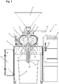
- the in the FIGS. 1 and 2 illustrated device for flaking or slicing food crop contains a in FIG. 1 in a section shown housing 1, in which two mutually parallel and separated by a gap 2 rollers 3 are rotatably mounted.
- the two rollers 3 may have a different surface.
- the two rollers can, for example, have a knurled or smooth surface.
- the two rollers 3 may contain a corrugated surface.
- At least one of the two rollers is arranged so adjustable within the housing 1 via an adjusting mechanism 4 that the gap 2 can be set between the two rollers 3 and changed as needed.
- the two rollers 3 are driven to rotate in the opposite direction.
- the housing 1 is mounted in the embodiment shown on a machine frame 8 provided with four height-adjustable feet 7.
- a feed or metering device 9 is arranged with a hopper 10.
- the feeding or metering device 9 is driven by a motor 11 via a transmission 12 and may e.g. in the form of a screw conveyor or the like. Be formed. This allows a controlled and precisely metered supply of grain to the two rollers 3 done.
- a collecting and discharging device 13 is arranged for the crop between the two rollers 3 crops.
- the collecting and discharging device 13 has a arranged below the two rollers 3 Collecting funnel 14 and a leading to a collecting container 15 outlet pipe 16.
- the projecting into the sump 15 outlet pipe 16 is adjustable in height.
- the collecting container 15 is arranged between the feet 7 of the machine frame 8 and can be closed by a lid.
- a suction device 17 is connected to generate a suction air 18 sucked in from below via the collecting and discharging device 13 and leading upwards along the outside of the rollers 3.
- the suction device 17 comprises a vacuum cleaner 19 and a suction line 20 with two above the two rollers 3 in the housing 1 inlet opening 21.
- the suction air 18 flows from below through the outlet pipe 16 and the collecting funnel 14 to the inner wall of the housing 1 facing outer sides of the two rollers 3 along the top of the housing 1.
- a throttle valve 22 is provided for regulating the air flow.
- the vacuum cleaner 19 has, in a conventional manner, a fan for generating a negative pressure.
- suitable filters may be arranged.
- FIG. 1 air can be sucked in via the outlet pipe 16 of the collecting and discharging device 13 via the negative pressure generated in the vacuum cleaner 19 and directed along the outer sides of the two rollers 3 facing the inner wall of the housing 1 to the intake pipe 21.
- the resulting during the treatment of the grain between the rollers 3 dust particles 23 can be guided to the top of the housing 1 and passed through the suction line 20 to the vacuum cleaner 19.
- the dust particles 23 can then be deposited via one or more filters.
- the grain bodies 24 deformed in the gap 2 between the two rolls 3 can fall down into the collecting container 15 via the collecting funnel 14 and the outlet pipe 16 of the collecting and discharging device 13.
- the vacuum cleaner 19 is arranged on one side of the machine frame. On the other side of the machine frame, a cabinet 25 is attached.
- FIG. 1 It can also be seen that two oppositely inclined guide plates 26 are arranged inside the housing 1 above the gap 2 formed between the two rollers 3.
- the food crop supplied via the feed or metering device 9 is directed, on the one hand, to the gap 2, on the other hand, it is through this Baffles 26, the intake 21 shielded and thereby prevents that fed through the feed or metering device 9 food crop is sucked in before the processing on the intake 21.
- two adjacent to the rollers 3 and adjustable Abstreiferbleche 27 are arranged within the housing 1 also. This can avoid that it comes to unwanted adhesion to the rollers 3.
Abstract
Die Erfindung betrifft eine Vorrichtung zum Flockieren oder Schroten von Speisegetreide mit einem Gehäuse (1), zwei zueinander parallelen und innerhalb des Gehäuses (1) durch einen Spalt (2) voneinander getrennt angeordneten, motorisch drehbaren Walzen (3), einer an der Oberseite des Gehäuses (1) angeordneten Einspeise- oder Dosiereinrichtung (9) für die Zuführung des Speisegetreides zu dem zwischen den Walzen (3) gebildeten Spalt (2) und einer an der Unterseite des Gehäuses (1) angeordneten Sammel- und Abführeinrichtung (13) für das zwischen den Walzen (3) verformte Speisegetreide. An das Gehäuse (1) ist eine Absaugeinrichtung (17) zur Erzeugung einer über die Sammel- und Abführeinrichtung (13) von unten angesaugten und entlang der Außenseite der Walzen (3) zur Oberseite des Gehäuses (1) führenden Ansaugluft (18) angeschlossen.The invention relates to a device for flaking or slicing food cereals with a housing (1), two mutually parallel and inside the housing (1) separated by a gap (2) arranged, motorized rotatable rollers (3), one at the top of the Housing (1) arranged feeding or metering device (9) for the supply of edible grain to the formed between the rollers (3) gap (2) and arranged on the underside of the housing (1) collecting and discharging means (13) for the between the rollers (3) deformed food crops. To the housing (1) is connected a suction device (17) for generating an intake air (18) sucked from below via the collection and discharge device (13) and leading along the outside of the rollers (3) to the upper side of the housing (1).
Description
Die Erfindung betrifft eine Vorrichtung zum Flockieren oder Schroten von Speisegetreide nach dem Oberbegriff des Anspruchs 1.The invention relates to a device for flaking or shredding food cereals according to the preamble of
Aus der
Ein Problem bekannter Vorrichtungen zum Flockieren oder Schroten von Speisegetreide besteht darin, dass bei der Bearbeitung des Speisegetreides Staub entsteht, der zu Störungen des Bearbeitungsprozesses und zu Beeinträchtigungen der Bearbeitungsqualität führen kann.One problem with known devices for flaking or slicing food crops is that dust is produced during processing of the food crop, which can lead to disruptions of the processing process and to impaired processing quality.
Aufgabe der Erfindung ist es, eine Vorrichtung zum Flockieren oder Schroten zu schaffen, die eine möglichst effektive und staubfreie Behandlung des Speisegetreides ermöglicht.The object of the invention is to provide a device for flocculation or crushing, which allows the most effective and dust-free treatment of the edible grain.
Diese Aufgabe wird durch eine Vorrichtung zum Flockieren oder Schroten mit den Merkmalen des Anspruchs 1 gelöst. Zweckmäßige Ausgestaltungen und vorteilhafte Weiterbildungen der Erfindung sind in den Unteransprüchen angegeben.This object is achieved by a device for flocculation or shredding with the features of
Bei der erfindungsgemäßen Vorrichtung zum Flockieren oder Schroten ist an das Gehäuse mit den zwei zueinander parallelen und innerhalb des Gehäuses durch einen Spalt voneinander getrennt angeordneten, motorisch drehbaren Walzen eine Absaugeinrichtung zur Erzeugung einer über die Sammel- und Abführeinrichtung von unten angesaugten und entlang der Außenseite der Walzen nach oben führenden Ansaugluft angeschlossen. Durch die Absaugeinrichtung kann der bei der Bearbeitung des Getreides entstehende Staub zur Oberseite des Gehäuses geleitet und aus dem Gehäuse abgeführt werden. Auf diese Weise kann eine staubfreie Bearbeitung erfolgen. Der Staub wird über die Absaugeinrichtung nach oben abgesaugt, während das zwischen den Walzen bearbeitete Getreide nach unten fällt und an der Unterseite des Gehäuses abgeführt werden kann. Durch den über die Absaugeinrichtung erzeugten Unterdruck im Gehäuse kann außerdem die Entstehung von Schwitzwasser und die dadurch bedingte Bildung von Schimmel verhindert werden. Dadurch wird eine besonders hygienische Bearbeitung ermöglicht.In the apparatus according to the invention for flocculation or crushing is on the housing with the two mutually parallel and within the housing by a gap separated from each other arranged, motor-rotatable rollers, a suction device for generating an over the collection and discharge device sucked from below and along the outside of the Rollers connected to the top leading intake air. By means of the suction device, the dust produced during the processing of the grain can be led to the top of the housing and removed from the housing. In this way, a dust-free processing can take place. The dust is sucked upwards via the suction device, while the grain processed between the rolls falls downwards and can be removed at the bottom of the housing. Due to the vacuum generated in the housing via the suction device can also the formation of Condensation and the resulting formation of mold can be prevented. This allows a particularly hygienic processing.
In einer besonders vorteilhaften Ausführung enthält die Absaugvorrichtung einen Staubsauger und eine Ansaugleitung mit zwei oberhalb der beiden Walzen in das Gehäuse einmündenden Ansaugstutzen. Dadurch kann der Staub besonders effektiv abgesaugt werden. In der Ansaugleitung kann zweckmäßigerweise ein Drosselventil angeordnet sein. Dadurch kann die Absaugleistung eingestellt und dadurch der Feinmehlanteil im bearbeiteten Getreide verändert werden. Es kann somit auch ein Windsichten durchgeführt werden.In a particularly advantageous embodiment, the suction device includes a vacuum cleaner and a suction line with two above the two rollers in the housing opening intake. This allows the dust to be extracted particularly effectively. A throttle valve may expediently be arranged in the intake line. As a result, the suction power can be adjusted and thereby the fine flour content in the processed grain can be changed. It can thus also be carried out an air classification.
In einer weiteren vorteilhaften Ausgestaltung kann an dem Gehäuse eine Stelleinrichtung zur Einstellung des Spalts zwischen den beiden Walzen angeordnet sein. Dadurch kann die Größe bzw. Form der Flocken oder geschroteten Körner eingestellt werden.In a further advantageous embodiment, an adjusting device for adjusting the gap between the two rollers can be arranged on the housing. Thereby, the size or shape of the flakes or crushed grains can be adjusted.
Innerhalb des Gehäuses können oberhalb des zwischen den beiden Walzen gebildeten Spalts entgegengesetzt schräge Leitbleche angeordnet sein. Durch diese Leitbleche kann das über die Einspeise- oder Dosiereinrichtung zugeführte Speisegetreide einerseits zu dem Spalt gelenkt werden, andrerseits werden durch diese Leitbleche die Ansaugstutzen abgeschirmt und verhindert, dass das über die Einspeise- oder Dosiereinrichtung zugeführte Speisegetreide noch vor der Bearbeitung über die Ansaugstutzen angesaugt wird.Within the housing oppositely inclined baffles can be arranged above the gap formed between the two rolls. Through these baffles fed via the feeding or metering food crops can be directed to the gap on the one hand, on the other hand are shielded by these baffles the intake manifold and prevents the fed via the feed or metering food crops is sucked before processing on the intake ,
Unterhalb des zwischen den beiden Walzen gebildeten Spalts können innerhalb des Gehäuses außerdem zwei an den Walzen anliegende und einstellbare Abstreiferbleche angeordnet sein. Durch solche Abstreiferbleche kann vermieden werden, dass es zu unerwünschten Anhaftungen an den Walzen kommt.Below the gap formed between the two rolls can also be arranged within the housing two voltage applied to the rollers and adjustable Abstreiferbleche. Such scraper plates can be used to prevent unwanted adhesion to the rollers.
In einer zweckmäßigen Ausführung kann die Sammel- und Abführeinrichtung einen Auffangtrichter und ein in einen Sammelbehälter führendes Austrittsrohr umfassen. Das Austrittsrohr kann in der Höhe verstellbar sein.In an expedient embodiment, the collecting and discharging device may comprise a collecting funnel and an outlet tube leading into a collecting container. The outlet pipe can be adjustable in height.
Die beiden Walzen werden vorzugsweise durch jeweils einen Motor über jeweils ein Getriebe angetrieben. Auch die Einspeise- oder Dosiereinrichtung kann von einem Motor über ein Getriebe angetrieben werden.The two rollers are preferably driven by a respective motor via a respective transmission. Also, the feed or metering device can be driven by a motor via a transmission.
Weitere Besonderheiten und Vorzüge der Erfindung ergeben sich aus der folgenden Beschreibung eines bevorzugten Ausführungsbeispiels anhand der Zeichnung. Es zeigen:
-
Figur 1 - eine Vorrichtung zum Flockieren oder Schroten von Speisegetreide in einer zum Teil geschnittenen Vorderansicht und
Figur 2- die in
Figur 1
- FIG. 1
- a device for flocculating or shredding food crops in a partially sectioned front view and
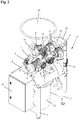
- FIG. 2
- in the
FIG. 1 shown device for flaking or slicing food crops in a perspective.
Die in den
Das Gehäuse 1 ist bei der gezeigten Ausführung auf einem mit vier höhenverstellbaren Füßen 7 versehenen Maschinengestell 8 montiert. Auf der Oberseite des Gehäuses 1 ist eine Einspeise- oder Dosiereinrichtung 9 mit einem Einfülltrichter 10 angeordnet. Über die Einspeise- oder Dosiereinrichtung 9 kann ein in dem Einfülltrichter 10 befindliches Getreide zum Spalt 2 zwischen den beiden Walzen 3 gefördert werden. Die Einspeise- oder Dosiereinrichtung 9 wird von einem Motor 11 über ein Getriebe 12 angetrieben und kann z.B. in Form einer Förderschnecke oder dgl. ausgebildet sein. Dadurch kann eine gesteuerte und genau dosierte Zufuhr von Getreide zu den beiden Walzen 3 erfolgen.The
An der Unterseite des Gehäuses 1 ist eine Sammel- und Abführeinrichtung 13 für das zwischen den beiden Walzen 3 verformte Speisegetreide angeordnet. Die Sammel- und Abführeinrichtung 13 weist einen unterhalb der beiden Walzen 3 angeordneten Auffangtrichter 14 und ein zu einem Sammelbehälter 15 führendes Austrittsrohr 16 auf. Das in den Sammelbehälter 15 ragende Austrittsrohr 16 ist in der Höhe verstellbar. Der Sammelbehälter 15 ist zwischen den Füßen 7 des Maschinengestells 8 angeordnet und kann durch einen Deckel verschlossen sein.At the bottom of the
An das Gehäuse 1 ist eine Absaugeinrichtung 17 zur Erzeugung einer über die Sammel- und Abführeinrichtung 13 von unten angesaugten und entlang der Außenseite der Walzen 3 nach oben führenden Absaugluft 18 angeschlossen. Die Absaugeinrichtung 17 umfasst einen Staubsauger 19 und eine Ansaugleitung 20 mit zwei oberhalb der beiden Walzen 3 in das Gehäuse 1 einmündenden Ansaugstutzen 21. Durch die Absaugeinrichtung 17 strömt die Absaugluft 18 von unten durch das Austrittsrohr 16 und den Auffangtrichter 14 an den zur Innenwand des Gehäuses 1 gewandten Außenseiten der beiden Walzen 3 entlang zur Oberseite des Gehäuses 1. In der Ansaugleitung 20 ist ein Drosselventil 22 zur Regulierung der Luftströmung vorgesehen. Der Staubsauger 19 weist in an sich bekannter Weise ein Gebläse zur Erzeugung eines Unterdrucks auf. In dem Staubsauger 19 können ferner geeignete Filter angeordnet sein.To the
Wie aus
Aus
Claims (10)
Applications Claiming Priority (1)
| Application Number | Priority Date | Filing Date | Title |
|---|---|---|---|
| DE202017100720.0U DE202017100720U1 (en) | 2017-02-10 | 2017-02-10 | Device for flaking or slicing food crops |
Publications (2)
| Publication Number | Publication Date |
|---|---|
| EP3360613A1 true EP3360613A1 (en) | 2018-08-15 |
| EP3360613B1 EP3360613B1 (en) | 2020-01-08 |
Family
ID=61157043
Family Applications (1)
| Application Number | Title | Priority Date | Filing Date |
|---|---|---|---|
| EP18154808.2A Active EP3360613B1 (en) | 2017-02-10 | 2018-02-02 | Device for flocking or crushing food cereals |
Country Status (2)
| Country | Link |
|---|---|
| EP (1) | EP3360613B1 (en) |
| DE (1) | DE202017100720U1 (en) |
Cited By (3)
| Publication number | Priority date | Publication date | Assignee | Title |
|---|---|---|---|---|
| CN109731634A (en) * | 2019-02-27 | 2019-05-10 | 广东世纪青山镍业有限公司 | A kind of ferronickel raw material are processed into the preparation process of nickel steel finished product |
| CN111359759A (en) * | 2020-03-30 | 2020-07-03 | 马绍成 | Smashing device method for feed manufacturing and efficiency calculation |
| CN111905876A (en) * | 2020-08-10 | 2020-11-10 | 张纪彬 | Preparation process of green organic rice flour |
Families Citing this family (2)
| Publication number | Priority date | Publication date | Assignee | Title |
|---|---|---|---|---|
| CN110052310A (en) * | 2019-05-20 | 2019-07-26 | 枣庄鑫金山智能机械股份有限公司 | A kind of combined vibrating sand making machine |
| CN112791775A (en) * | 2021-01-13 | 2021-05-14 | 王志海 | Grain grinding device |
Citations (6)
| Publication number | Priority date | Publication date | Assignee | Title |
|---|---|---|---|---|
| US1188323A (en) * | 1914-11-21 | 1916-06-20 | True B Richardson | Aspirating-shoe. |
| DE1054809B (en) * | 1956-07-13 | 1959-04-09 | Simon Ltd Henry | Roller mill |
| WO2013117864A1 (en) * | 2012-02-08 | 2013-08-15 | Vicat | Plant for crushing mineral materials |
| CN204234135U (en) * | 2014-11-08 | 2015-04-01 | 湖北大顶山制药有限公司 | A kind of traditional Chinese medicine powder millstone |
| CN104923340A (en) * | 2015-06-19 | 2015-09-23 | 黄斌 | Speed-adjustable dust collecting and crushing device used for crushing coal mines |
| CN205570420U (en) * | 2016-02-24 | 2016-09-14 | 宁波大学 | Multi -functional environmental protection milling machine |
Family Cites Families (1)
| Publication number | Priority date | Publication date | Assignee | Title |
|---|---|---|---|---|
| CH697410B1 (en) | 2005-08-29 | 2008-09-30 | Alb Lehmann Lindmuehle Ag | Method for the production of flakes from grains of corn and legume, comprises heating the grains in a heating zone at a first temperature and moistening in a moistening zone at a moisture content, and cooling the grains in a resting zone |
-
2017
- 2017-02-10 DE DE202017100720.0U patent/DE202017100720U1/en active Active
-
2018
- 2018-02-02 EP EP18154808.2A patent/EP3360613B1/en active Active
Patent Citations (6)
| Publication number | Priority date | Publication date | Assignee | Title |
|---|---|---|---|---|
| US1188323A (en) * | 1914-11-21 | 1916-06-20 | True B Richardson | Aspirating-shoe. |
| DE1054809B (en) * | 1956-07-13 | 1959-04-09 | Simon Ltd Henry | Roller mill |
| WO2013117864A1 (en) * | 2012-02-08 | 2013-08-15 | Vicat | Plant for crushing mineral materials |
| CN204234135U (en) * | 2014-11-08 | 2015-04-01 | 湖北大顶山制药有限公司 | A kind of traditional Chinese medicine powder millstone |
| CN104923340A (en) * | 2015-06-19 | 2015-09-23 | 黄斌 | Speed-adjustable dust collecting and crushing device used for crushing coal mines |
| CN205570420U (en) * | 2016-02-24 | 2016-09-14 | 宁波大学 | Multi -functional environmental protection milling machine |
Cited By (3)
| Publication number | Priority date | Publication date | Assignee | Title |
|---|---|---|---|---|
| CN109731634A (en) * | 2019-02-27 | 2019-05-10 | 广东世纪青山镍业有限公司 | A kind of ferronickel raw material are processed into the preparation process of nickel steel finished product |
| CN111359759A (en) * | 2020-03-30 | 2020-07-03 | 马绍成 | Smashing device method for feed manufacturing and efficiency calculation |
| CN111905876A (en) * | 2020-08-10 | 2020-11-10 | 张纪彬 | Preparation process of green organic rice flour |
Also Published As
| Publication number | Publication date |
|---|---|
| DE202017100720U1 (en) | 2018-05-15 |
| EP3360613B1 (en) | 2020-01-08 |
Similar Documents
| Publication | Publication Date | Title |
|---|---|---|
| EP3360613B1 (en) | Device for flocking or crushing food cereals | |
| DE3026001A1 (en) | RICE MILL | |
| EP1562451B1 (en) | Device for processing tobacco during the production of cigarettes | |
| AT16260U1 (en) | Device for separating foreign substances from a bulk material | |
| EP2186575B1 (en) | Device for separating a bulk mixture in a fluid medium | |
| CH620859A5 (en) | System for reclaiming plastics | |
| DE1532213A1 (en) | Tobacco distributor with rib separator | |
| CH660073A5 (en) | VACUUM DRYING DEVICE. | |
| DE3407871A1 (en) | Process and apparatus for producing a constant mass flow rate or volumetric flow rate gas/solid particle free jet of defined velocity | |
| DE102008058998B4 (en) | Process for the screening or classification of cut, vegetable bulk material, in particular tobacco, and apparatus for carrying out the process | |
| DE2360057C2 (en) | Method and device for starting up a grinding plant | |
| DE1927262B1 (en) | Cleaning device for combine harvester | |
| DE2727308A1 (en) | THRESHER | |
| DE960344C (en) | Device for pneumatic cleaning and sifting of shredded tobacco leaves | |
| DE102007020267B4 (en) | Device for separating a loose mixture in a fluid medium | |
| DE2939809C2 (en) | ||
| DE2009521B2 (en) | Device for automatically dividing cut tobacco into ready-to-pack weight portions | |
| DE625874C (en) | Impact shredder for grinding grainy substances such as grain or the like. | |
| DE2717009A1 (en) | Plastic waste recovery - using a shredder, cleaners and dewatering towers | |
| DE2135295A1 (en) | Machine for pre-cleaning and cleaning of grains and seeds | |
| DE1910255B2 (en) | Device for the continuous production of edible fat emulsions such as butter and margarine | |
| EP0012790A1 (en) | Machine for husking and cleaning cereals | |
| DE708239C (en) | Device for the pneumatic sifting of shredded tobacco leaves | |
| DE942357C (en) | Ascending air sorting machine for cleaning and sorting grain and seeds of various kinds | |
| EP4000734A1 (en) | Roller mill with improved product collection |
Legal Events
| Date | Code | Title | Description |
|---|---|---|---|
| PUAI | Public reference made under article 153(3) epc to a published international application that has entered the european phase |
Free format text: ORIGINAL CODE: 0009012 |
|
| STAA | Information on the status of an ep patent application or granted ep patent |
Free format text: STATUS: THE APPLICATION HAS BEEN PUBLISHED |
|
| AK | Designated contracting states |
Kind code of ref document: A1 Designated state(s): AL AT BE BG CH CY CZ DE DK EE ES FI FR GB GR HR HU IE IS IT LI LT LU LV MC MK MT NL NO PL PT RO RS SE SI SK SM TR |
|
| AX | Request for extension of the european patent |
Extension state: BA ME |
|
| STAA | Information on the status of an ep patent application or granted ep patent |
Free format text: STATUS: REQUEST FOR EXAMINATION WAS MADE |
|
| 17P | Request for examination filed |
Effective date: 20190215 |
|
| RBV | Designated contracting states (corrected) |
Designated state(s): AL AT BE BG CH CY CZ DE DK EE ES FI FR GB GR HR HU IE IS IT LI LT LU LV MC MK MT NL NO PL PT RO RS SE SI SK SM TR |
|
| GRAP | Despatch of communication of intention to grant a patent |
Free format text: ORIGINAL CODE: EPIDOSNIGR1 |
|
| STAA | Information on the status of an ep patent application or granted ep patent |
Free format text: STATUS: GRANT OF PATENT IS INTENDED |
|
| INTG | Intention to grant announced |
Effective date: 20190805 |
|
| GRAS | Grant fee paid |
Free format text: ORIGINAL CODE: EPIDOSNIGR3 |
|
| GRAA | (expected) grant |
Free format text: ORIGINAL CODE: 0009210 |
|
| STAA | Information on the status of an ep patent application or granted ep patent |
Free format text: STATUS: THE PATENT HAS BEEN GRANTED |
|
| AK | Designated contracting states |
Kind code of ref document: B1 Designated state(s): AL AT BE BG CH CY CZ DE DK EE ES FI FR GB GR HR HU IE IS IT LI LT LU LV MC MK MT NL NO PL PT RO RS SE SI SK SM TR |
|
| REG | Reference to a national code |
Ref country code: GB Ref legal event code: FG4D Free format text: NOT ENGLISH |
|
| REG | Reference to a national code |
Ref country code: CH Ref legal event code: EP |
|
| REG | Reference to a national code |
Ref country code: DE Ref legal event code: R096 Ref document number: 502018000599 Country of ref document: DE |
|
| REG | Reference to a national code |
Ref country code: IE Ref legal event code: FG4D Free format text: LANGUAGE OF EP DOCUMENT: GERMAN |
|
| REG | Reference to a national code |
Ref country code: AT Ref legal event code: REF Ref document number: 1222033 Country of ref document: AT Kind code of ref document: T Effective date: 20200215 |
|
| REG | Reference to a national code |
Ref country code: DE Ref legal event code: R082 Ref document number: 502018000599 Country of ref document: DE Representative=s name: TBK, DE |
|
| REG | Reference to a national code |
Ref country code: NL Ref legal event code: MP Effective date: 20200108 |
|
| REG | Reference to a national code |
Ref country code: LT Ref legal event code: MG4D |
|
| PG25 | Lapsed in a contracting state [announced via postgrant information from national office to epo] |
Ref country code: RS Free format text: LAPSE BECAUSE OF FAILURE TO SUBMIT A TRANSLATION OF THE DESCRIPTION OR TO PAY THE FEE WITHIN THE PRESCRIBED TIME-LIMIT Effective date: 20200108 Ref country code: NL Free format text: LAPSE BECAUSE OF FAILURE TO SUBMIT A TRANSLATION OF THE DESCRIPTION OR TO PAY THE FEE WITHIN THE PRESCRIBED TIME-LIMIT Effective date: 20200108 Ref country code: FI Free format text: LAPSE BECAUSE OF FAILURE TO SUBMIT A TRANSLATION OF THE DESCRIPTION OR TO PAY THE FEE WITHIN THE PRESCRIBED TIME-LIMIT Effective date: 20200108 Ref country code: LT Free format text: LAPSE BECAUSE OF FAILURE TO SUBMIT A TRANSLATION OF THE DESCRIPTION OR TO PAY THE FEE WITHIN THE PRESCRIBED TIME-LIMIT Effective date: 20200108 Ref country code: NO Free format text: LAPSE BECAUSE OF FAILURE TO SUBMIT A TRANSLATION OF THE DESCRIPTION OR TO PAY THE FEE WITHIN THE PRESCRIBED TIME-LIMIT Effective date: 20200408 Ref country code: PT Free format text: LAPSE BECAUSE OF FAILURE TO SUBMIT A TRANSLATION OF THE DESCRIPTION OR TO PAY THE FEE WITHIN THE PRESCRIBED TIME-LIMIT Effective date: 20200531 |
|
| PG25 | Lapsed in a contracting state [announced via postgrant information from national office to epo] |
Ref country code: SE Free format text: LAPSE BECAUSE OF FAILURE TO SUBMIT A TRANSLATION OF THE DESCRIPTION OR TO PAY THE FEE WITHIN THE PRESCRIBED TIME-LIMIT Effective date: 20200108 Ref country code: LV Free format text: LAPSE BECAUSE OF FAILURE TO SUBMIT A TRANSLATION OF THE DESCRIPTION OR TO PAY THE FEE WITHIN THE PRESCRIBED TIME-LIMIT Effective date: 20200108 Ref country code: HR Free format text: LAPSE BECAUSE OF FAILURE TO SUBMIT A TRANSLATION OF THE DESCRIPTION OR TO PAY THE FEE WITHIN THE PRESCRIBED TIME-LIMIT Effective date: 20200108 Ref country code: GR Free format text: LAPSE BECAUSE OF FAILURE TO SUBMIT A TRANSLATION OF THE DESCRIPTION OR TO PAY THE FEE WITHIN THE PRESCRIBED TIME-LIMIT Effective date: 20200409 Ref country code: IS Free format text: LAPSE BECAUSE OF FAILURE TO SUBMIT A TRANSLATION OF THE DESCRIPTION OR TO PAY THE FEE WITHIN THE PRESCRIBED TIME-LIMIT Effective date: 20200508 Ref country code: BG Free format text: LAPSE BECAUSE OF FAILURE TO SUBMIT A TRANSLATION OF THE DESCRIPTION OR TO PAY THE FEE WITHIN THE PRESCRIBED TIME-LIMIT Effective date: 20200408 |
|
| REG | Reference to a national code |
Ref country code: DE Ref legal event code: R097 Ref document number: 502018000599 Country of ref document: DE |
|
| REG | Reference to a national code |
Ref country code: BE Ref legal event code: MM Effective date: 20200229 |
|
| PG25 | Lapsed in a contracting state [announced via postgrant information from national office to epo] |
Ref country code: RO Free format text: LAPSE BECAUSE OF FAILURE TO SUBMIT A TRANSLATION OF THE DESCRIPTION OR TO PAY THE FEE WITHIN THE PRESCRIBED TIME-LIMIT Effective date: 20200108 Ref country code: CZ Free format text: LAPSE BECAUSE OF FAILURE TO SUBMIT A TRANSLATION OF THE DESCRIPTION OR TO PAY THE FEE WITHIN THE PRESCRIBED TIME-LIMIT Effective date: 20200108 Ref country code: SK Free format text: LAPSE BECAUSE OF FAILURE TO SUBMIT A TRANSLATION OF THE DESCRIPTION OR TO PAY THE FEE WITHIN THE PRESCRIBED TIME-LIMIT Effective date: 20200108 Ref country code: ES Free format text: LAPSE BECAUSE OF FAILURE TO SUBMIT A TRANSLATION OF THE DESCRIPTION OR TO PAY THE FEE WITHIN THE PRESCRIBED TIME-LIMIT Effective date: 20200108 Ref country code: LU Free format text: LAPSE BECAUSE OF NON-PAYMENT OF DUE FEES Effective date: 20200202 Ref country code: MC Free format text: LAPSE BECAUSE OF FAILURE TO SUBMIT A TRANSLATION OF THE DESCRIPTION OR TO PAY THE FEE WITHIN THE PRESCRIBED TIME-LIMIT Effective date: 20200108 Ref country code: EE Free format text: LAPSE BECAUSE OF FAILURE TO SUBMIT A TRANSLATION OF THE DESCRIPTION OR TO PAY THE FEE WITHIN THE PRESCRIBED TIME-LIMIT Effective date: 20200108 Ref country code: SM Free format text: LAPSE BECAUSE OF FAILURE TO SUBMIT A TRANSLATION OF THE DESCRIPTION OR TO PAY THE FEE WITHIN THE PRESCRIBED TIME-LIMIT Effective date: 20200108 Ref country code: DK Free format text: LAPSE BECAUSE OF FAILURE TO SUBMIT A TRANSLATION OF THE DESCRIPTION OR TO PAY THE FEE WITHIN THE PRESCRIBED TIME-LIMIT Effective date: 20200108 |
|
| PLBE | No opposition filed within time limit |
Free format text: ORIGINAL CODE: 0009261 |
|
| STAA | Information on the status of an ep patent application or granted ep patent |
Free format text: STATUS: NO OPPOSITION FILED WITHIN TIME LIMIT |
|
| 26N | No opposition filed |
Effective date: 20201009 |
|
| PG25 | Lapsed in a contracting state [announced via postgrant information from national office to epo] |
Ref country code: IT Free format text: LAPSE BECAUSE OF FAILURE TO SUBMIT A TRANSLATION OF THE DESCRIPTION OR TO PAY THE FEE WITHIN THE PRESCRIBED TIME-LIMIT Effective date: 20200108 Ref country code: IE Free format text: LAPSE BECAUSE OF NON-PAYMENT OF DUE FEES Effective date: 20200202 Ref country code: FR Free format text: LAPSE BECAUSE OF NON-PAYMENT OF DUE FEES Effective date: 20200308 |
|
| PG25 | Lapsed in a contracting state [announced via postgrant information from national office to epo] |
Ref country code: SI Free format text: LAPSE BECAUSE OF FAILURE TO SUBMIT A TRANSLATION OF THE DESCRIPTION OR TO PAY THE FEE WITHIN THE PRESCRIBED TIME-LIMIT Effective date: 20200108 Ref country code: PL Free format text: LAPSE BECAUSE OF FAILURE TO SUBMIT A TRANSLATION OF THE DESCRIPTION OR TO PAY THE FEE WITHIN THE PRESCRIBED TIME-LIMIT Effective date: 20200108 Ref country code: BE Free format text: LAPSE BECAUSE OF NON-PAYMENT OF DUE FEES Effective date: 20200229 |
|
| PG25 | Lapsed in a contracting state [announced via postgrant information from national office to epo] |
Ref country code: CH Free format text: LAPSE BECAUSE OF NON-PAYMENT OF DUE FEES Effective date: 20210228 Ref country code: LI Free format text: LAPSE BECAUSE OF NON-PAYMENT OF DUE FEES Effective date: 20210228 |
|
| PGRI | Patent reinstated in contracting state [announced from national office to epo] |
Ref country code: CH Effective date: 20211012 Ref country code: LI Effective date: 20211012 |
|
| PG25 | Lapsed in a contracting state [announced via postgrant information from national office to epo] |
Ref country code: TR Free format text: LAPSE BECAUSE OF FAILURE TO SUBMIT A TRANSLATION OF THE DESCRIPTION OR TO PAY THE FEE WITHIN THE PRESCRIBED TIME-LIMIT Effective date: 20200108 Ref country code: MT Free format text: LAPSE BECAUSE OF FAILURE TO SUBMIT A TRANSLATION OF THE DESCRIPTION OR TO PAY THE FEE WITHIN THE PRESCRIBED TIME-LIMIT Effective date: 20200108 Ref country code: CY Free format text: LAPSE BECAUSE OF FAILURE TO SUBMIT A TRANSLATION OF THE DESCRIPTION OR TO PAY THE FEE WITHIN THE PRESCRIBED TIME-LIMIT Effective date: 20200108 |
|
| PG25 | Lapsed in a contracting state [announced via postgrant information from national office to epo] |
Ref country code: MK Free format text: LAPSE BECAUSE OF FAILURE TO SUBMIT A TRANSLATION OF THE DESCRIPTION OR TO PAY THE FEE WITHIN THE PRESCRIBED TIME-LIMIT Effective date: 20200108 Ref country code: AL Free format text: LAPSE BECAUSE OF FAILURE TO SUBMIT A TRANSLATION OF THE DESCRIPTION OR TO PAY THE FEE WITHIN THE PRESCRIBED TIME-LIMIT Effective date: 20200108 |
|
| GBPC | Gb: european patent ceased through non-payment of renewal fee |
Effective date: 20220202 |
|
| PG25 | Lapsed in a contracting state [announced via postgrant information from national office to epo] |
Ref country code: GB Free format text: LAPSE BECAUSE OF NON-PAYMENT OF DUE FEES Effective date: 20220202 |
|
| PGFP | Annual fee paid to national office [announced via postgrant information from national office to epo] |
Ref country code: CH Payment date: 20230307 Year of fee payment: 6 Ref country code: AT Payment date: 20230215 Year of fee payment: 6 |
|
| P01 | Opt-out of the competence of the unified patent court (upc) registered |
Effective date: 20231107 |
|
| PGFP | Annual fee paid to national office [announced via postgrant information from national office to epo] |
Ref country code: AT Payment date: 20240216 Year of fee payment: 7 |
|
| PGFP | Annual fee paid to national office [announced via postgrant information from national office to epo] |
Ref country code: DE Payment date: 20240227 Year of fee payment: 7 Ref country code: CH Payment date: 20240301 Year of fee payment: 7 |