EP3359622B1 - Verbesserte elektrophoretische medien für niedrige temperaturen - Google Patents
Verbesserte elektrophoretische medien für niedrige temperaturen Download PDFInfo
- Publication number
- EP3359622B1 EP3359622B1 EP16854159.7A EP16854159A EP3359622B1 EP 3359622 B1 EP3359622 B1 EP 3359622B1 EP 16854159 A EP16854159 A EP 16854159A EP 3359622 B1 EP3359622 B1 EP 3359622B1
- Authority
- EP
- European Patent Office
- Prior art keywords
- electrophoretic medium
- electrophoretic
- particles
- charge control
- charged particles
- Prior art date
- Legal status (The legal status is an assumption and is not a legal conclusion. Google has not performed a legal analysis and makes no representation as to the accuracy of the status listed.)
- Active
Links
Images


Classifications
-
- G—PHYSICS
- G02—OPTICS
- G02F—OPTICAL DEVICES OR ARRANGEMENTS FOR THE CONTROL OF LIGHT BY MODIFICATION OF THE OPTICAL PROPERTIES OF THE MEDIA OF THE ELEMENTS INVOLVED THEREIN; NON-LINEAR OPTICS; FREQUENCY-CHANGING OF LIGHT; OPTICAL LOGIC ELEMENTS; OPTICAL ANALOGUE/DIGITAL CONVERTERS
- G02F1/00—Devices or arrangements for the control of the intensity, colour, phase, polarisation or direction of light arriving from an independent light source, e.g. switching, gating or modulating; Non-linear optics
- G02F1/01—Devices or arrangements for the control of the intensity, colour, phase, polarisation or direction of light arriving from an independent light source, e.g. switching, gating or modulating; Non-linear optics for the control of the intensity, phase, polarisation or colour
- G02F1/165—Devices or arrangements for the control of the intensity, colour, phase, polarisation or direction of light arriving from an independent light source, e.g. switching, gating or modulating; Non-linear optics for the control of the intensity, phase, polarisation or colour based on translational movement of particles in a fluid under the influence of an applied field
- G02F1/1675—Constructional details
- G02F1/1679—Gaskets; Spacers; Sealing of cells; Filling or closing of cells
- G02F1/1681—Gaskets; Spacers; Sealing of cells; Filling or closing of cells having two or more microcells partitioned by walls, e.g. of microcup type
-
- C—CHEMISTRY; METALLURGY
- C09—DYES; PAINTS; POLISHES; NATURAL RESINS; ADHESIVES; COMPOSITIONS NOT OTHERWISE PROVIDED FOR; APPLICATIONS OF MATERIALS NOT OTHERWISE PROVIDED FOR
- C09D—COATING COMPOSITIONS, e.g. PAINTS, VARNISHES OR LACQUERS; FILLING PASTES; CHEMICAL PAINT OR INK REMOVERS; INKS; CORRECTING FLUIDS; WOODSTAINS; PASTES OR SOLIDS FOR COLOURING OR PRINTING; USE OF MATERIALS THEREFOR
- C09D5/00—Coating compositions, e.g. paints, varnishes or lacquers, characterised by their physical nature or the effects produced; Filling pastes
- C09D5/44—Coating compositions, e.g. paints, varnishes or lacquers, characterised by their physical nature or the effects produced; Filling pastes for electrophoretic applications
- C09D5/4407—Coating compositions, e.g. paints, varnishes or lacquers, characterised by their physical nature or the effects produced; Filling pastes for electrophoretic applications with polymers obtained by polymerisation reactions involving only carbon-to-carbon unsaturated bonds
-
- C—CHEMISTRY; METALLURGY
- C09—DYES; PAINTS; POLISHES; NATURAL RESINS; ADHESIVES; COMPOSITIONS NOT OTHERWISE PROVIDED FOR; APPLICATIONS OF MATERIALS NOT OTHERWISE PROVIDED FOR
- C09D—COATING COMPOSITIONS, e.g. PAINTS, VARNISHES OR LACQUERS; FILLING PASTES; CHEMICAL PAINT OR INK REMOVERS; INKS; CORRECTING FLUIDS; WOODSTAINS; PASTES OR SOLIDS FOR COLOURING OR PRINTING; USE OF MATERIALS THEREFOR
- C09D5/00—Coating compositions, e.g. paints, varnishes or lacquers, characterised by their physical nature or the effects produced; Filling pastes
- C09D5/44—Coating compositions, e.g. paints, varnishes or lacquers, characterised by their physical nature or the effects produced; Filling pastes for electrophoretic applications
- C09D5/4407—Coating compositions, e.g. paints, varnishes or lacquers, characterised by their physical nature or the effects produced; Filling pastes for electrophoretic applications with polymers obtained by polymerisation reactions involving only carbon-to-carbon unsaturated bonds
- C09D5/4411—Homopolymers or copolymers of acrylates or methacrylates
-
- C—CHEMISTRY; METALLURGY
- C09—DYES; PAINTS; POLISHES; NATURAL RESINS; ADHESIVES; COMPOSITIONS NOT OTHERWISE PROVIDED FOR; APPLICATIONS OF MATERIALS NOT OTHERWISE PROVIDED FOR
- C09D—COATING COMPOSITIONS, e.g. PAINTS, VARNISHES OR LACQUERS; FILLING PASTES; CHEMICAL PAINT OR INK REMOVERS; INKS; CORRECTING FLUIDS; WOODSTAINS; PASTES OR SOLIDS FOR COLOURING OR PRINTING; USE OF MATERIALS THEREFOR
- C09D5/00—Coating compositions, e.g. paints, varnishes or lacquers, characterised by their physical nature or the effects produced; Filling pastes
- C09D5/44—Coating compositions, e.g. paints, varnishes or lacquers, characterised by their physical nature or the effects produced; Filling pastes for electrophoretic applications
- C09D5/4476—Coating compositions, e.g. paints, varnishes or lacquers, characterised by their physical nature or the effects produced; Filling pastes for electrophoretic applications comprising polymerisation in situ
-
- C—CHEMISTRY; METALLURGY
- C09—DYES; PAINTS; POLISHES; NATURAL RESINS; ADHESIVES; COMPOSITIONS NOT OTHERWISE PROVIDED FOR; APPLICATIONS OF MATERIALS NOT OTHERWISE PROVIDED FOR
- C09D—COATING COMPOSITIONS, e.g. PAINTS, VARNISHES OR LACQUERS; FILLING PASTES; CHEMICAL PAINT OR INK REMOVERS; INKS; CORRECTING FLUIDS; WOODSTAINS; PASTES OR SOLIDS FOR COLOURING OR PRINTING; USE OF MATERIALS THEREFOR
- C09D5/00—Coating compositions, e.g. paints, varnishes or lacquers, characterised by their physical nature or the effects produced; Filling pastes
- C09D5/44—Coating compositions, e.g. paints, varnishes or lacquers, characterised by their physical nature or the effects produced; Filling pastes for electrophoretic applications
- C09D5/448—Coating compositions, e.g. paints, varnishes or lacquers, characterised by their physical nature or the effects produced; Filling pastes for electrophoretic applications characterised by the additives used
-
- C—CHEMISTRY; METALLURGY
- C09—DYES; PAINTS; POLISHES; NATURAL RESINS; ADHESIVES; COMPOSITIONS NOT OTHERWISE PROVIDED FOR; APPLICATIONS OF MATERIALS NOT OTHERWISE PROVIDED FOR
- C09K—MATERIALS FOR MISCELLANEOUS APPLICATIONS, NOT PROVIDED FOR ELSEWHERE
- C09K3/00—Materials not provided for elsewhere
-
- C—CHEMISTRY; METALLURGY
- C09—DYES; PAINTS; POLISHES; NATURAL RESINS; ADHESIVES; COMPOSITIONS NOT OTHERWISE PROVIDED FOR; APPLICATIONS OF MATERIALS NOT OTHERWISE PROVIDED FOR
- C09K—MATERIALS FOR MISCELLANEOUS APPLICATIONS, NOT PROVIDED FOR ELSEWHERE
- C09K9/00—Tenebrescent materials, i.e. materials for which the range of wavelengths for energy absorption is changed as a result of excitation by some form of energy
- C09K9/02—Organic tenebrescent materials
-
- G—PHYSICS
- G02—OPTICS
- G02F—OPTICAL DEVICES OR ARRANGEMENTS FOR THE CONTROL OF LIGHT BY MODIFICATION OF THE OPTICAL PROPERTIES OF THE MEDIA OF THE ELEMENTS INVOLVED THEREIN; NON-LINEAR OPTICS; FREQUENCY-CHANGING OF LIGHT; OPTICAL LOGIC ELEMENTS; OPTICAL ANALOGUE/DIGITAL CONVERTERS
- G02F1/00—Devices or arrangements for the control of the intensity, colour, phase, polarisation or direction of light arriving from an independent light source, e.g. switching, gating or modulating; Non-linear optics
- G02F1/01—Devices or arrangements for the control of the intensity, colour, phase, polarisation or direction of light arriving from an independent light source, e.g. switching, gating or modulating; Non-linear optics for the control of the intensity, phase, polarisation or colour
- G02F1/165—Devices or arrangements for the control of the intensity, colour, phase, polarisation or direction of light arriving from an independent light source, e.g. switching, gating or modulating; Non-linear optics for the control of the intensity, phase, polarisation or colour based on translational movement of particles in a fluid under the influence of an applied field
- G02F1/166—Devices or arrangements for the control of the intensity, colour, phase, polarisation or direction of light arriving from an independent light source, e.g. switching, gating or modulating; Non-linear optics for the control of the intensity, phase, polarisation or colour based on translational movement of particles in a fluid under the influence of an applied field characterised by the electro-optical or magneto-optical effect
- G02F1/167—Devices or arrangements for the control of the intensity, colour, phase, polarisation or direction of light arriving from an independent light source, e.g. switching, gating or modulating; Non-linear optics for the control of the intensity, phase, polarisation or colour based on translational movement of particles in a fluid under the influence of an applied field characterised by the electro-optical or magneto-optical effect by electrophoresis
-
- G—PHYSICS
- G02—OPTICS
- G02F—OPTICAL DEVICES OR ARRANGEMENTS FOR THE CONTROL OF LIGHT BY MODIFICATION OF THE OPTICAL PROPERTIES OF THE MEDIA OF THE ELEMENTS INVOLVED THEREIN; NON-LINEAR OPTICS; FREQUENCY-CHANGING OF LIGHT; OPTICAL LOGIC ELEMENTS; OPTICAL ANALOGUE/DIGITAL CONVERTERS
- G02F1/00—Devices or arrangements for the control of the intensity, colour, phase, polarisation or direction of light arriving from an independent light source, e.g. switching, gating or modulating; Non-linear optics
- G02F1/01—Devices or arrangements for the control of the intensity, colour, phase, polarisation or direction of light arriving from an independent light source, e.g. switching, gating or modulating; Non-linear optics for the control of the intensity, phase, polarisation or colour
- G02F1/165—Devices or arrangements for the control of the intensity, colour, phase, polarisation or direction of light arriving from an independent light source, e.g. switching, gating or modulating; Non-linear optics for the control of the intensity, phase, polarisation or colour based on translational movement of particles in a fluid under the influence of an applied field
- G02F1/1675—Constructional details
- G02F2001/1678—Constructional details characterised by the composition or particle type
Definitions
- Particle-based electrophoretic displays have been the subject of intense research and development for a number of years.
- a plurality of charged particles (sometimes referred to as pigment particles) move through a fluid under the influence of an electric field.
- the electric field is typically provided by a conductive film or a transistor, such as a field-effect transistor.
- Electrophoretic displays have good brightness and contrast, wide viewing angles, state bistability, and low power consumption when compared with liquid crystal displays. Such electrophoretic displays have slower switching speeds than LCD displays, however, and electrophoretic displays are typically too slow to display real-time video. Additionally, the electrophoretic displays can be sluggish at low temperatures because the viscosity of the fluid limits the movement of the electrophoretic particles.
- electrophoretic displays can be found in everyday products such as electronic books (e-readers), mobile phones and mobile phone covers, smart cards, signs, watches, shelf labels, and flash drives.
- electrophoretic media essentially display only two colors, with a gradient between the black and white extremes, known as “grayscale.”
- Such electrophoretic media either use a single type of electrophoretic particle having a first color in a colored fluid having a second, different color (in which case, the first color is displayed when the particles lie adjacent the viewing surface of the display and the second color is displayed when the particles are spaced from the viewing surface), or first and second types of electrophoretic particles having differing first and second colors in an uncolored fluid. In the latter case, the first color is displayed when the first type of particles lie adjacent the viewing surface of the display and the second color is displayed when the second type of particles lie adjacent the viewing surface).
- the two colors are black and white.
- a color filter array may be deposited over the viewing surface of the monochrome (black and white) display. Displays with color filter arrays rely on area sharing and color blending to create color stimuli. The available display area is shared between three or four primary colors such as red/green/blue (RGB) or red/green/blue/white (RGBW), and the filters can be arranged in one-dimensional (stripe) or two-dimensional (2x2) repeat patterns. Other choices of primary colors or more than three primaries are also known in the art.
- the three (in the case of RGB displays) or four (in the case of RGBW displays) sub-pixels are chosen small enough so that at the intended viewing distance they visually blend together to a single pixel with a uniform color stimulus ('color blending').
- the inherent disadvantage of area sharing is that the colorants are always present, and colors can only be modulated by switching the corresponding pixels of the underlying monochrome display to white or black (switching the corresponding primary colors on or off).
- each of the red, green, blue and white primaries occupy one fourth of the display area (one sub-pixel out of four), with the white sub-pixel being as bright as the underlying monochrome display white, and each of the colored sub-pixels being no lighter than one third of the monochrome display white.
- the brightness of the white color shown by the display as a whole cannot be more than one half of the brightness of the white sub-pixel (white areas of the display are produced by displaying the one white sub-pixel out of each four, plus each colored sub-pixel in its colored form being equivalent to one third of a white sub-pixel, so the three colored sub-pixels combined contribute no more than the one white sub-pixel).
- the brightness and saturation of colors is lowered by area-sharing with color pixels switched to black.
- Area sharing is especially problematic when mixing yellow because it is lighter than any other color of equal brightness, and saturated yellow is almost as bright as white. Switching the blue pixels (one fourth of the display area) to black makes the yellow too dark.
- US 2014/0340430 A1 describes an electrophoretic medium comprising a non-polar fluid having a low dielectric constant (typically about 2), a plurality of charged particles (which may be of one or more colors) and charge control agents.
- a low dielectric constant typically about 2
- a plurality of charged particles which may be of one or more colors
- charge control agents which may be of one or more colors
- Paragraphs [0098] to [0105] of this published application discuss in detail preferred types of charge control agents.
- a first addressing impulse when a first addressing impulse is applied to the medium, a first species of particles move in one direction relative to the electric field, but when a second addressing impulse, larger than the first addressing impulse, is applied to the medium, the first species of particles move in the opposed direction relative to the electric field.
- US 6 113 810 A describes an electrophoretic display having a dielectric dispersion comprising a dielectric (non-polar) fluid, a first plurality of particles of a first color having a surface charge of a selected polarity dispersed within the dielectric fluid, and a second plurality of particles of a second color having a surface charge of opposite polarity to that of the first plurality and a steric repulsion thereto preventing coagulation of the first and second pluralities.
- Charge control agents are added to the dispersion to establish opposite polarities on the respective particles.
- US 2001/0039879 A1 describes an air filtration filter formed of material such as a resin bound fiber forming a woven or non-woven fabric, thermoplastic netting, tackifying resin solution and/or antimicrobial agents in which said material is compounded or coated to contain 0.01 to 20% by weight of a positive and/or negative charge control agent.
- the filter is charged to apply an electrostatic charge thereto.
- Paragraphs [0073] to [0079] of this published application contain a detailed discussion of appropriate charge control agents, which operate by triboelectric charging of particles.
- electrophoretic media and electrophoretic devices display complex behaviors. For instance, it has been discovered that simple "on/off" voltage pulses are insufficient to achieve high-quality text in electronic readers. Rather, complicated “waveforms” are needed to drive the particles between states and to assure that the new displayed text does not retain a memory of the previous text, i.e., a "ghost.” See, for example, US 2015/0213765 A1 .
- the internal phase i.e., the mixture of particles (pigment) and fluid
- unexpected behavior may result from impurities in the fluid, pigments, or encapsulation medium. Accordingly, it is difficult to predict how an electrophoretic display will respond to variations in the internal phase composition.
- MIT Massachusetts Institute of Technology
- E Ink Corporation E Ink Corporation
- Such encapsulated media comprise numerous small capsules, each of which itself comprises an internal phase containing electrophoretically-mobile particles in a fluid medium, and a capsule wall surrounding the internal phase.
- the capsules are themselves held within a polymeric binder to form a coherent layer positioned between two electrodes.
- the technologies described in these patents and applications include:
- the invention provides an electrophoretic medium that allows for faster switching speeds and a larger dynamic range when used in electrophoretic displays.
- the electrophoretic medium of the invention is generally similar to those described in the aforementioned US 2014/0340430 A1 and US 6 113 810 A in comprising a non-polar fluid, a plurality of first charged particles, and charge control agents.
- the electrophoretic medium of the invention is characterized in that the charge control agents include a quaternary amine and an unsaturated polymeric tail comprising monomers of at least 10 carbon atoms in length.
- the charge control agents may form complexes with the first charged particles.
- electrophoretic medium will include at least a second charged particle
- electrophoretic media of the invention may include many different types of charge particles, each of which may have different charge and mobility properties from the other particles.
- the additional charged particles may also be complexed with the charge control agents, e.g., including a quaternary amine and an unsaturated polymeric tail comprising monomers of at least 10 carbon atoms in length, however other charge control agents can be used in addition.
- the ratio of charge control agent to first charged particles is greater than 1:1000 (wt/wt), e.g., greater than 1:500 (wt/wt), e.g., greater than 1:300 (wt/wt), e.g., greater than 1:200 (wt/wt), e.g., greater than 1:100 (wt/wt).
- the charge control agents including a quaternary amine and an unsaturated polymeric tail comprising monomers of at least 10 carbon atoms in length, may include multiple double bonds.
- the polymeric tail may be the condensation product of an unsaturated carboxylic acid monomer having a secondary alcohol.
- the resulting polymer will include a backbone of repeating alkene units as well as pendant alkyl chains (i.e., a comb polymer).
- Other polymeric tails, derived from other unsaturated monomers, are also suitable for use with the invention.
- the polymer tail may be the condensation product of an unsaturated carboxylic acid monomer having a primary alcohol.
- the polymer tail may be the condensation product of an unsaturated carboxylic acid monomer having a tertiary alcohol.
- Electrophoretic media of the invention are typically encapsulated when used in a display to improve the switching speed and to discourage gravitational settling.
- the electrophoretic media may be encapsulated in microcells or a protein coacervate, such as a coacervate comprise gelatin.
- the electrophoretic media are dispersed, as a suspension, in a polymer.
- the encapsulated medium When incorporated into a display, the encapsulated medium may have a dynamic range of 55L* at 0 °C when driven by a 15V, 500ms drive pulse.
- the present invention provides electrophoretic media.
- the media may be incorporated into displays, or into front plane laminates or inverted front plane laminates that are coupled to a backplane to make a display.
- the media include a non-polar fluid and a plurality of first charged particles dispersed in the non-polar fluid, wherein the first charged particles are complexed with a charge control agent including a quaternary amine and an unsaturated polymeric tail comprising monomers of at least 10 carbon atoms in length.
- the formulations show improved switching speed and dynamic range at low temperatures (i.e., approximately 0 °C).
- gray state is used herein in its conventional meaning in the imaging art to refer to a state intermediate two extreme optical states of a pixel, and does not necessarily imply a black-white transition between these two extreme states.
- E Ink patents and published applications referred to below describe electrophoretic displays in which the extreme states are white and deep blue, so that an intermediate gray state would actually be pale blue. Indeed, as already mentioned, the change in optical state may not be a color change at all.
- black and white may be used hereinafter to refer to the two extreme optical states of a display, and should be understood as normally including extreme optical states which are not strictly black and white, for example the aforementioned white and dark blue states.
- bistable and bistability are used herein in their conventional meaning in the art to refer to displays comprising display elements having first and second display states differing in at least one optical property, and such that after any given element has been driven, by means of an addressing pulse of finite duration, to assume either its first or second display state, after the addressing pulse has terminated, that state will persist for at least several times, for example at least four times, the minimum duration of the addressing pulse required to change the state of the display element.
- U.S. Patent No. 7,170,670 some particle-based electrophoretic displays capable of gray scale are stable not only in their extreme black and white states but also in their intermediate gray states, and the same is true of some other types of electro-optic displays. This type of display is properly called multi-stable rather than bistable, although for convenience the term bistable may be used herein to cover both bistable and multi-stable displays.
- impulse when used to refer to driving an electrophoretic display, is used herein to refer to the integral of the applied voltage with respect to time during the period in which the display is driven.
- a particle that absorbs, scatters, or reflects light, either in a broad band or at selected wavelengths, is referred to herein as a colored or pigment particle.
- a related type of electrophoretic display is a so-called microcell electrophoretic display.
- the charged particles and the fluid are not encapsulated within microcapsules but instead are retained within a plurality of cavities formed within a carrier medium, typically a polymeric film.
- a carrier medium typically a polymeric film.
- electrophoretic media require the presence of a fluid.
- this fluid is a liquid, but electrophoretic media can be produced using gaseous fluids; see, for example, Kitamura, T., et al., Electrical toner movement for electronic paper-like display, IDW Japan, 2001, Paper HCS1-1, and Yamaguchi, Y., et al., Toner display using insulative particles charged triboelectrically, IDW Japan, 2001, Paper AMD4-4). See also U.S. Patents Nos. 7,321,459 and 7,236,291 .
- Such gas-based electrophoretic media appear to be susceptible to the same types of problems due to particle settling as liquid-based electrophoretic media, when the media are used in an orientation which permits such settling, for example in a sign where the medium is disposed in a vertical plane. Indeed, particle settling appears to be a more serious problem in gas-based electrophoretic media than in liquid-based ones, since the lower viscosity of gaseous suspending fluids as compared with liquid ones allows more rapid settling of the electrophoretic particles.
- An encapsulated electrophoretic display typically does not suffer from the clustering and settling failure mode of traditional electrophoretic devices and provides further advantages, such as the ability to print or coat the display on a wide variety of flexible and rigid substrates.
- Use of the word printing is intended to include all forms of printing and coating, including, but without limitation: pre-metered coatings such as patch die coating, slot or extrusion coating, slide or cascade coating, curtain coating; roll coating such as knife over roll coating, forward and reverse roll coating; gravure coating; dip coating; spray coating; meniscus coating; spin coating; brush coating; air knife coating; silk screen printing processes; electrostatic printing processes; thermal printing processes; ink jet printing processes; electrophoretic deposition (See U.S. Patent No. 7,339,715 ); and other similar techniques.)
- pre-metered coatings such as patch die coating, slot or extrusion coating, slide or cascade coating, curtain coating
- roll coating such as knife over roll coating, forward and reverse roll coating
- gravure coating dip coating
- spray coating meniscus
- U.S. Patent No. 6,982,178 describes a method of assembling electrophoretic displays (including an encapsulated electrophoretic display).
- this patent describes a so-called front plane laminate (FPL) which comprises, in order, a light-transmissive electrically-conductive layer; a layer of a solid electro-optic medium in electrical contact with the electrically-conductive layer; an adhesive layer; and a release sheet.
- FPL front plane laminate
- the light-transmissive electrically-conductive layer will be carried on a light-transmissive substrate, which is preferably flexible, in the sense that the substrate can be manually wrapped around a drum (say) 10 inches (254 mm) in diameter without permanent deformation.
- the term light-transmissive is used in this patent and herein to mean that the layer thus designated transmits sufficient light to enable an observer, looking through that layer, to observe the change in display states of the electro-optic medium, which will normally be viewed through the electrically-conductive layer and adjacent substrate (if present); in cases where the electro-optic medium displays a change in reflectivity at non-visible wavelengths, the term light-transmissive should of course be interpreted to refer to transmission of the relevant non-visible wavelengths.
- the substrate will typically be a polymeric film, and will normally have a thickness in the range of about 1 to about 25 mil (25 to 634 ⁇ m), preferably about 2 to about 10 mil (51 to 254 ⁇ m).
- the electrically-conductive layer is conveniently a thin metal or metal oxide layer of, for example, aluminum or indium tin oxide (ITO), or may be a conductive polymer.
- ITO indium tin oxide
- PET Poly(ethylene terephthalate) films coated with aluminum or ITO are available commercially, for example as aluminized Mylar (Mylar is a Registered Trade Mark) from E.I. du Pont de Nemours & Company, Wilmington DE, and such commercial materials may be used with good results in the front plane laminate.
- Assembly of an electro-optic display using such a front plane laminate may be effected by removing the release sheet from the front plane laminate and contacting the adhesive layer with the backplane under conditions effective to cause the adhesive layer to adhere to the backplane, thereby securing the adhesive layer, layer of electro-optic medium and electrically-conductive layer to the backplane.
- This process is well-adapted to mass production since the front plane laminate may be mass produced, typically using roll-to-roll coating techniques, and then cut into pieces of any size needed for use with specific backplanes.
- U.S. Patent No. 7,561,324 describes a so-called double release sheet which is essentially a simplified version of the front plane laminate of the aforementioned U.S. Patent No. 6,982,178 .
- One form of the double release sheet comprises a layer of a solid electro-optic medium sandwiched between two adhesive layers, one or both of the adhesive layers being covered by a release sheet.
- Another form of the double release sheet comprises a layer of a solid electro-optic medium sandwiched between two release sheets.
- Both forms of the double release film are intended for use in a process generally similar to the process for assembling an electro-optic display from a front plane laminate already described, but involving two separate laminations; typically, in a first lamination the double release sheet is laminated to a front electrode to form a front sub-assembly, and then in a second lamination the front sub-assembly is laminated to a backplane to form the final display, although the order of these two laminations could be reversed if desired.
- U. S. Patent No. 7,839,564 describes a so-called inverted front plane laminate, which is a variant of the front plane laminate described in the aforementioned U.S. Patent No. 6,982,178 .
- This inverted front plane laminate comprises, in order, at least one of a light-transmissive protective layer and a light-transmissive electrically-conductive layer; an adhesive layer; a layer of a solid electro-optic medium; and a release sheet.
- This inverted front plane laminate is used to form an electro-optic display having a layer of lamination adhesive between the electro-optic layer and the front electrode or front substrate; a second, typically thin layer of adhesive may or may not be present between the electro-optic layer and a backplane.
- Such electro-optic displays can combine good resolution with good low temperature performance.
- Multilayer, stacked electrophoretic displays are known in the art; see, for example, J. Heikenfeld, P. Drzaic, J-S Yeo and T. Koch, Journal of the SID, 19(2), 2011, pp. 129-156 .
- ambient light passes through images in each of the three subtractive primary colors, in precise analogy with conventional color printing.
- U.S. Patent No. 6,727,873 describes a stacked electrophoretic display in which three layers of switchable cells are placed over a reflective background.
- Similar displays are known in which colored particles are moved laterally (see International Application No. WO 2008/065605 ) or, using a combination of vertical and lateral motion, sequestered into micropits.
- each layer is provided with electrodes that serve to concentrate or disperse the colored particles on a pixel-by-pixel basis, so that each of the three layers requires a layer of thin-film transistors (TFT's) (two of the three layers of TFT's must be substantially transparent) and a light-transmissive counter-electrode.
- TFT's thin-film transistors
- Such a complex arrangement of electrodes is costly to manufacture, and in the present state of the art it is difficult to provide an adequately transparent plane of pixel electrodes, especially as the white state of the display must be viewed through several layers of electrodes.
- Multi-layer displays also suffer from parallax problems as the thickness of the display stack approaches or exceeds the pixel size.
- U.S. Applications Publication Nos. 2012/0008188 and 2012/0134009 describe multicolor electrophoretic displays having a single back plane comprising independently addressable pixel electrodes and a common, light-transmissive front electrode. Between the back plane and the front electrode is disposed a plurality of electrophoretic layers. Displays described in these applications are capable of rendering any of the primary colors (red, green, blue, cyan, magenta, yellow, white and black) at any pixel location.
- optical losses in an electrophoretic layer closest to the viewing surface may affect the appearance of images formed in underlying electrophoretic layers.
- U.S. Patent Application Publication No. 2013/0208338 describes a color display comprising an electrophoretic fluid which comprises one or two types of pigment particles dispersed in a clear and colorless or colored solvent, the electrophoretic fluid being sandwiched between a common electrode and a plurality of driving electrodes. The driving electrodes are kept at a certain distance in order to expose a background layer.
- U.S. Patent Application Publication No. 2014/0177031 describes a method for driving a display cell filled with an electrophoretic fluid comprising two types of charged particles carrying opposite charge polarities and of two contrast colors.
- the two types of pigment particles are dispersed in a colored solvent or in a solvent with non-charged or slightly charged colored particles dispersed therein.
- the method comprises driving the display cell to display the color of the solvent or the color of the non-charged or slightly charged colored particles by applying a driving voltage which is about 1 to about 20% of the full driving voltage.
- a driving voltage which is about 1 to about 20% of the full driving voltage.
- U.S. Patent Application Publication No. 2014/0092465 and 2014/0092466 describe an electrophoretic fluid, and a method for driving an electrophoretic display.
- the fluid comprises first, second and third type of pigment particles, all of which are dispersed in a solvent or solvent mixture.
- the first and second types of pigment particles carry opposite charge polarities, and the third type of pigment particles has a charge level being less than about 50% of the charge level of the first or second type.
- the three types of pigment particles have different levels of threshold voltage, or different levels of mobility, or both.
- U.S. Patent Application Publication No. 2007/0031031 describes an image processing device for processing image data in order to display an image on a display medium in which each pixel is capable of displaying white, black and one other color.
- U.S. Patent Applications Publication Nos. 2008/0151355 ; 2010/0188732 ; and 2011/0279885 describe a color display in which mobile particles move through a porous structure.
- U.S. Patent Applications Publication Nos. 2008/0303779 and 2010/0020384 describe a display medium comprising first, second and third particles of differing colors. The first and second particles can form aggregates, and the smaller third particles can move through apertures left between the aggregated first and second particles.
- 2011/0134506 describes a display device including an electrophoretic display element including plural types of particles enclosed between a pair of substrates, at least one of the substrates being translucent and each of the respective plural types of particles being charged with the same polarity, differing in optical properties, and differing in either in migration speed and/or electric field threshold value for moving, a translucent display-side electrode provided at the substrate side where the translucent substrate is disposed, a first back-side electrode provided at the side of the other substrate, facing the display-side electrode, and a second back-side electrode provided at the side of the other substrate, facing the display-side electrode; and a voltage control section that controls the voltages applied to the display-side electrode, the first back-side electrode, and the second back-side electrode, such that the types of particles having the fastest migration speed from the plural types of particles, or the types of particles having the lowest threshold value from the plural types of particles, are moved, in sequence by each of the different types of particles, to the first back-side electrode or to the second back-side electrode, and then the particles that
- U.S. Patent Applications Publication Nos. 2011/0175939 ; 2011/0298835 ; 2012/0327504 ; and 2012/0139966 describe color displays which rely upon aggregation of multiple particles and threshold voltages.
- U.S. Patent Application Publication No. 2013/0222884 describes an electrophoretic particle, which contains a colored particle containing a charged group-containing polymer and a coloring agent, and a branched silicone-based polymer being attached to the colored particle and containing, as copolymerization components, a reactive monomer and at least one monomer selected from a specific group of monomers.
- 2013/0222885 describes a dispersion liquid for an electrophoretic display containing a dispersion medium, a colored electrophoretic particle group dispersed in the dispersion medium and migrates in an electric field, a non-electrophoretic particle group which does not migrate and has a color different from that of the electrophoretic particle group, and a compound having a neutral polar group and a hydrophobic group, which is contained in the dispersion medium in a ratio of about 0.01 to about 1 mass % based on the entire dispersion liquid.
- 2013/0222886 describes a dispersion liquid for a display including floating particles containing: core particles including a colorant and a hydrophilic resin; and a shell covering a surface of each of the core particles and containing a hydrophobic resin with a difference in a solubility parameter of 7.95 (J/cm 3 ) 1/2 or more.
- U.S. Patent Applications Publication Nos. 2013/0222887 and 2013/0222888 describe an electrophoretic particle having specified chemical compositions.
- 2014/0104675 describes a particle dispersion including first and second colored particles that move in response to an electric field, and a dispersion medium, the second colored particles having a larger diameter than the first colored particles and the same charging characteristic as a charging characteristic of the first color particles, and in which the ratio (Cs/Cl) of the charge amount Cs of the first colored particles to the charge amount Cl of the second colored particles per unit area of the display is less than or equal to 5.
- U.S. Patent Applications Publication Nos. 2012/0314273 and 2014/0002889 describe an electrophoresis device including a plurality of first and second electrophoretic particles included in an insulating liquid, the first and second particles having different charging characteristics that are different from each other; the device further comprising a porous layer included in the insulating liquid and formed of a fibrous structure.
- the polymers formed on particles by the present processes include charged or chargeable groups, since such groups are useful in controlling the charge on the electrophoretic particles.
- the charge on electrophoretic particles is normally controlled by adding a charge control agent (CCA) to the electrophoretic medium.
- CCA charge control agent
- the CCA is a surfactant which adsorbs on to the particles and varies the charge thereon.
- any mixture including charged particles and a CCA that gives the desired performance is suitable.
- the CCAs may be complexed with the charged particles, absorbed into the particles, or they may be covalently bound to the surface of the particles.
- the particles and the CCAs may exist in a charge complex, or be loosely associated via van der Waals forces.
- Charge control agents often charge the particles by poorly understood and uncontrolled processes, and can lead to undesirably high conductivity of the electrophoretic medium. Also, since the charge control agent is only physically adsorbed on to the particles and is not bound thereto, changes in conditions may cause partial or complete desorption of the charge control agent from the particles, with consequent undesirable changes in the electrophoretic characteristics of the particles. The desorbed charge control agent might resorb on to other surfaces within the electrophoretic medium, and such resorption has the potential for causing additional problems.
- charge control agents are especially difficult in dual particle electrophoretic media, where a charge control agent may adsorb on to the surface of one or both types of electrophoretic particles.
- a charge control agent may adsorb on to the surface of one or both types of electrophoretic particles.
- the present inventors have observed cases where the addition of a charge control agent to a dual particle electrophoretic medium, which was intended to be of the type in which the two types of particles bear charges of opposite polarity, resulted in some particles of one type becoming positively charged, and other particles of the same type becoming negatively charged, thus rendering the medium essentially useless for its intended purpose.
- the charge control agent it is also possible for the charge control agent to adsorb on to the capsule wall. Providing charged groups within the bound polymer ensures that these charged groups remain fixed on to the particle, with essentially no tendency to desorb (unless the polymer chains themselves are rendered capable of desorption, as already discussed).
- charge control agents comprising a quaternary amine and an unsaturated polymeric tail comprising monomers of at least 10 carbon atoms in length are preferred.
- Quaternary amines comprise a quaternary ammonium cation [NR 1 R 2 R 3 R 4 ] + bonded to an organic molecule, for example an alkyl group or an aryl group.
- Quaternary amine charge control agents typically include a long non-polar tail attached to the charged ammonium cation, such as the families of fatty acid quaternary amines offered by Akzo Nobel under the Registered Trademark ARQUAD
- the quaternary amine charge control agents may be purchased in a purified form, or the charge control agents may be purchased as a reaction product that has formed a quaternary amine charge control agent.
- SOLSPERSE 17000 (“SOLSPERSE” is a Registered Trademark of Lubrizol Corporation), may be purchased as a reaction product of 12-hydroxy-octadecanoic acid homopolymer with N,N-dimethyl-1,3-propanediamine and methylbisulfate.
- the non-polar tail of the quaternary amine charge control agents is unsaturated, i.e., contains at least one carbon-carbon double bond.
- unsaturated quaternary amine charge control agents when unsaturated quaternary amine charge control agents are incorporated into electrophoretic media, the media have improved switching speeds, especially at low temperatures.
- the non-polar tail of the quaternary amine charge control agents is formed from a polymeric or oligomeric compound, such as a polyester.
- the polyester may be formed via a condensation reaction of carboxylic acid, e.g., a fatty acid, having a secondary amine.
- the condensation reaction will result in repeating units having at least one carbon-carbon double bond (i.e., unsaturated), with repeating pendant carbon chains, which may be saturated or unsaturated.
- unsaturated polymeric quaternary amine charge control agents are commercially available from Lubrizol under the tradenames SOLSPERSE 19000 and SOLSPERSE 16000.
- the overall length of the monomer from which the tail is formed is at least 10 carbon atoms in length, for example 14 carbon atoms in length, for example 18 carbon atoms in length.
- the charge control agents may be added to the electrophoretic medium at a concentration of greater than 1 g of charge control agent for every 100 g of charged particles.
- the charge control agent to charged particle ratio may be 1:30 (wt/wt), e.g., 1:25 (wt/wt), e.g., 1:20 (wt/wt).
- the charge control agents may have an average molecular weight of greater than 12,000 grams/mole, e.g., greater than 13,000 grams/mole, e.g., greater than 14,000 grams/mole, e.g., greater than 15,000 grams/mole, e.g., greater than 16,000 grams/mole, e.g., greater than 17,000 grams/mole, e.g., greater than greater than 1 g of charge control agent for every 100 g of charged particles.
- the charge control agent to charged particle ratio may be 1:30 (wt/wt), e.g., 1:25 (wt/wt), e.g., 1:20 (wt/wt).
- the charge control agents may have an average molecular weight of greater than 12,000 grams/mole, e.g., greater than 13,000 grams/mole, e.g., greater than 14,000 grams/mole, e.g., greater than 15,000 grams/mole, e.g., greater than 16,000 grams/mole, e.g., greater than 17,000 grams/mole, e.g., greater than 18,000 grams/mole, e.g., greater than 19,000 grams/mole, e.g., greater than 20,000 grams/mole, e.g., greater than 21,000 grams/mole.
- the average molecular weight of the charge control agent may be between 14,000 grams/mole and 22,000 grams/mole, e.g., between 15,000 grams/mole and 20,000 grams/mole. In some embodiments, the charge control agents have an average molecular weight of about 19,000 grams/mole.
- Additional charge control agents may be used, with or without charged groups in polymer coatings, to provide good electrophoretic mobility to the electrophoretic particles.
- Stabilizers may be used to prevent agglomeration of the electrophoretic particles, as well as prevent the electrophoretic particles from irreversibly depositing onto the capsule wall.
- Either component can be constructed from materials across a wide range of molecular weights (low molecular weight, oligomeric, or polymeric), and may be a single pure compound or a mixture.
- An optional charge control agent or charge director may be used. These constituents typically consist of low molecular weight surfactants, polymeric agents, or blends of one or more components and serve to stabilize or otherwise modify the sign and/or magnitude of the charge on the electrophoretic particles. Additional pigment properties which may be relevant are the particle size distribution, the chemical composition, and the lightfastness.
- Charge adjuvants may also be added. These materials increase the effectiveness of the charge control agents or charge directors.
- the charge adjuvant may be a polyhydroxy compound or an aminoalcohol compound, and is preferably soluble in the suspending fluid in an amount of at least 2% by weight.
- polyhydroxy compounds which contain at least two hydroxyl groups include, but are not limited to, ethylene glycol, 2,4,7,9-tetramethyldecyne-4,7-diol, poly(propylene glycol), pentaethylene glycol, tripropylene glycol, triethylene glycol, glycerol, pentaerythritol, glycerol tris(12-hydroxystearate), propylene glycerol monohydroxystearate, and ethylene glycol monohydroxystearate.
- the charge adjuvant is preferably present in the suspending fluid in an amount of about 1 to about 100 milligrams per gram ("mg/g") of the particle mass, and more preferably about 50 to about 200 mg/g.
- the particles may be very convenient to treat the particles (after any preliminary treatment such as silica coating) with a mixture of two reagents, one of which carries the charged or chargeable group (or a group which will eventually be treated to produce the desired charged or chargeable group), and the other of which carries the polymerizable or polymerization-initiating group.
- the two reagents have the same, or essentially the same, functional group which reacts with the particle surface so that, if minor variations in reaction conditions occur, the relative rates at which the reagents react with the particles will change in a similar manner, and the ratio between the number of charged or chargeable groups and the number of polymerizable or polymerization-initiating groups will remain substantially constant. It will be appreciated that this ratio can be varied and controlled by varying the relative molar amounts of the two (or more) reagents used in the mixture.
- reagents which provide chargeable sites but not polymerizable or polymerization-initiating groups include 3-(trimethoxysilyl)propylamine, N-[3-(trimethoxysilyl)propyl]diethylenetriamine, N-[3-(trimethoxysilyl)propyl]ethylene and 1-[3-(trimethoxysilyl)propyl]urea; all these silane reagents may be purchased from United Chemical Technologies, Inc., Bristol, Pa., 19007.
- an example of a reagent which provides polymerizable groups but not charged or chargeable groups is 3-(trimethoxysilyl)propyl methacrylate.
- the charged particle CCA complexes formed may be used with advantage in all of the types of electrophoretic display (namely single particle, opposite charge dual particle, same polarity dual particle and polymer dispersed) previously described.
- the charged particle CCA complexes of the present invention are especially useful in opposite charge dual particle electrophoretic displays, which are especially difficult to stabilize, since as already mentioned the two types of particles of opposite polarity are inherently attracted towards one another and hence have a strong tendency to form aggregates which may interfere with the electrophoretic operation of the display.
- the described charged particle CCA complexes may be used to construct an electrophoretic medium having only one type of particle, such as used in a variable transmission window.
- the described charged particle CCA complexes may be used to construct an electrophoretic medium to be used in black/white displays, i.e., including black particles and white particles.
- the described charged particle CCA complexes may be used to construct an electrophoretic medium to be used in colors displays, i.e., including, for example, three, four, five, six, seven, or eight different types of particles.
- a display may be constructed where the particles include black, white, and red or black, white, and yellow.
- the display may include red, green, and blue particles, or cyan, magenta, and yellow particles, or red, green, blue, and yellow particles.
- the electrophoretic media of the present invention may employ the same components and manufacturing techniques as in the aforementioned Massachusetts Institute of Technology and E Ink Corporation patents and applications.
- the suspending fluid containing the particles should be chosen based on properties such as density, refractive index, and solubility.
- a preferred suspending fluid has a low dielectric constant (about 2), high volume resistivity (about 1015 ohm-cm), low viscosity (less than 5 centistokes (“cst”)), low toxicity and environmental impact, low water solubility (less than 10 parts per million (“ppm”)), high specific gravity (greater than 1.5), a high boiling point (greater than 90° C.), and a low refractive index (less than 1.2).
- non-polar fluid may be based on concerns of chemical inertness, density matching to the electrophoretic particle, or chemical compatibility with both the electrophoretic particle and bounding capsule (in the case of encapsulated electrophoretic displays).
- the viscosity of the fluid should be low when movement of the particles is desired.
- the refractive index of the suspending fluid may also be substantially matched to that of the particles. As used herein, the refractive index of a suspending fluid "is substantially matched" to that of a particle if the difference between their respective refractive indices is between about zero and about 0.3, and is preferably between about 0.05 and about 0.2.
- Non-polar organic solvents such as halogenated organic solvents, saturated linear or branched hydrocarbons, silicone oils, and low molecular weight halogen-containing polymers are some useful non-polar fluids.
- the non-polar fluid may comprise a single fluid.
- the non-polar fluid will, however, often be a blend of more than one fluid in order to tune its chemical and physical properties.
- the non-polar fluid may contain additional surface modifiers to modify the surface energy or charge of the electrophoretic particle or bounding capsule.
- Reactants or solvents for the microencapsulation process oil soluble monomers, for example
- Additional charge control agents can also be added to the suspending fluid.
- Useful organic solvents include, but are not limited to, epoxides, such as decane epoxide and dodecane epoxide; vinyl ethers, such as cyclohexyl vinyl ether and Decave (Registered Trade Mark of International Flavors & Fragrances, Inc., New York, N.Y.); and aromatic hydrocarbons, such as toluene and naphthalene.
- Useful halogenated organic solvents include, but are not limited to, tetrafluorodibromoethylene, tetrachloroethylene, trifluorochloroethylene, 1,2,4-trichlorobenzene and carbon tetrachloride. These materials have high densities.
- Useful hydrocarbons include, but are not limited to, dodecane, tetradecane, the aliphatic hydrocarbons in the Isopar (Registered Trade Mark) series (Exxon, Houston, Tex.), Norpar (Registered Trade Mark) (a series of normal paraffinic liquids), Shell-Sol (Registered Trade Mark) (Shell, Houston, Tex.), and Sol-Trol (Registered Trade Mark) (Shell), naphtha, and other petroleum solvents. These materials usually have low densities.
- silicone oils include, but are not limited to, octamethyl cyclosiloxane and higher molecular weight cyclic siloxanes, poly(methyl phenyl siloxane), hexamethyldisiloxane, and polydimethylsiloxane. These materials usually have low densities.
- Useful low molecular weight halogen-containing polymers include, but are not limited to, poly(chlorotrifluoroethylene) polymer (Halogenated Hydrocarbon Inc., River Edge, N.J.), Galden (Registered Trade Mark) (a perfluorinated ether from Ausimont, Morristown, N.J.), or Krytox (Registered Trade Mark) from du Pont (Wilmington, Del.).
- the suspending fluid is a poly (chlorotrifluoroethylene) polymer.
- this polymer has a degree of polymerization from about 2 to about 10. Many of the above materials are available in a range of viscosities, densities, and boiling points.
- the non-polar fluid must be capable of being formed into small droplets prior to a capsule being formed.
- Processes for forming small droplets include flow-through jets, membranes, nozzles, or orifices, as well as shear-based emulsifying schemes.
- the formation of small drops may be assisted by electrical or sonic fields.
- Surfactants and polymers can be used to aid in the stabilization and emulsification of the droplets in the case of an emulsion type encapsulation.
- One surfactant for use in displays of the invention is sodium dodecylsulfate.
- the non-polar fluid will include an optically absorbing dye.
- This dye must be soluble in the fluid, but will generally be insoluble in the other components of the capsule.
- the dye can be a pure compound, or blends of dyes to achieve a particular color, including black.
- the dyes can be fluorescent, which would produce a display in which the fluorescence properties depend on the position of the particles.
- the dyes can be photoactive, changing to another color or becoming colorless upon irradiation with either visible or ultraviolet light, providing another means for obtaining an optical response. Dyes could also be polymerizable by, for example, thermal, photochemical or chemical diffusion processes, forming a solid absorbing polymer inside the bounding shell.
- dyes that can be used in encapsulated electrophoretic displays. Properties important here include light fastness, solubility in the suspending liquid, color, and cost. These dyes are generally chosen from the classes of azo, anthraquinone, and triphenylmethane type dyes and may be chemically modified so as to increase their solubility in the oil phase and reduce their adsorption by the particle surface.
- Useful azo dyes include, but are not limited to: the Oil Red dyes, and the Sudan Red and Sudan Black series of dyes.
- Useful anthraquinone dyes include, but are not limited to: the Oil Blue dyes, and the Macrolex Blue series of dyes.
- Useful triphenylmethane dyes include, but are not limited to, Michler's hydrol, Malachite Green, Crystal Violet, and Auramine O.
- charging results as an acid-base reaction between some moiety present in the continuous phase and the particle surface.
- useful materials are those which are capable of participating in such a reaction, or any other charging reaction as known in the art.
- Particle dispersion stabilizers may be added to prevent particle flocculation or attachment to the capsule walls.
- non-aqueous surfactants include, but are not limited to, glycol ethers, acetylenic glycols, alkanolamides, sorbitol derivatives, alkyl amines, quaternary amines, imidazolines, dialkyl oxides, and sulfosuccinates.
- a bistable electrophoretic medium it may be desirable to include in the suspending fluid a polymer having a number average molecular weight in excess of about 20,000, this polymer being essentially non-absorbing on the electrophoretic particles; poly(isobutylene) is a preferred polymer for this purpose. See US 2002/0180687 A1 and the corresponding International Application WO 02/079869 .
- Encapsulation of the internal phase may be accomplished in a number of different ways. Numerous suitable procedures for microencapsulation are detailed in both Microencapsulation, Processes and Applications, (I. E. Vandegaer, ed.), Plenum Press, New York, N.Y (1974 ) and Gutcho, Microcapsules and Microencapsulation Techniques, Noyes Data Corp., Park Ridge, N.J. (1976 ). The processes fall into several general categories, all of which can be applied to the present invention: interfacial polymerization, in situ polymerization, physical processes, such as coextrusion and other phase separation processes, in-liquid curing, and simple/complex coacervation.
- Useful materials for simple coacervation processes to form the capsule include, but are not limited to, gelatin, poly(vinyl alcohol), poly(vinyl acetate), and cellulosic derivatives, such as, for example, carboxymethylcellulose.
- Useful materials for complex coacervation processes include, but are not limited to, gelatin, acacia, carageenan, carboxymethylcellulose, hydrolyzed styrene anhydride copolymers, agar, alginate, casein, albumin, methyl vinyl ether co-maleic anhydride, and cellulose phthalate.
- Useful materials for phase separation processes include, but are not limited to, polystyrene, poly(methyl methacrylate) (PMMA), poly(ethyl methacrylate), poly(butyl methacrylate), ethyl cellulose, poly(vinylpyridine), and polyacrylonitrile.
- Useful materials for in situ polymerization processes include, but are not limited to, polyhydroxyamides, with aldehydes, melamine, or urea and formaldehyde; water-soluble oligomers of the condensate of melamine, or urea and formaldehyde; and vinyl monomers, such as, for example, styrene, methyl methacrylate (MMA) and acrylonitrile.
- useful materials for interfacial polymerization processes include, but are not limited to, diacyl chlorides, such as, for example, sebacoyl, adipoyl, and di- or poly-amines or alcohols, and isocyanates.
- useful emulsion polymerization materials may include, but are not limited to, styrene, vinyl acetate, acrylic acid, butyl acrylate, t-butyl acrylate, methyl methacrylate, and butyl methacrylate.
- Capsules produced may be dispersed into a curable carrier, resulting in an ink which may be printed or coated on large and arbitrarily shaped or curved surfaces using conventional printing and coating techniques.
- capsule properties include the distribution of capsule radii; electrical, mechanical, diffusion, and optical properties of the capsule wall; and chemical compatibility with the internal phase of the capsule.
- the capsule wall generally has a high electrical resistivity. Although it is possible to use walls with relatively low resistivities, this may limit performance in requiring relatively higher addressing voltages.
- the capsule wall should also be mechanically strong (although if the finished capsule powder is to be dispersed in a curable polymeric binder for coating, mechanical strength is not as critical).
- the capsule wall should generally not be porous. If, however, it is desired to use an encapsulation procedure that produces porous capsules, these can be overcoated in a post-processing step (i.e., a second encapsulation). Moreover, if the capsules are to be dispersed in a curable binder, the binder will serve to close the pores.
- the capsule walls should be optically clear.
- the wall material may, however, be chosen to match the refractive index of the internal phase of the capsule (i.e., the suspending fluid) or a binder in which the capsules are to be dispersed. For some applications (e.g., interposition between two fixed electrodes), monodispersed capsule radii are desirable.
- An encapsulation technique that is suited to the present invention involves a polymerization between urea and formaldehyde in an aqueous phase of an oil/water emulsion in the presence of a negatively charged, carboxyl-substituted, linear hydrocarbon polyelectrolyte material.
- the resulting capsule wall is a urea/formaldehyde copolymer, which discretely encloses the internal phase.
- the capsule is clear, mechanically strong, and has good resistivity properties.
- the related technique of in situ polymerization utilizes an oil/water emulsion, which is formed by dispersing the electrophoretic fluid (i.e., the dielectric liquid containing a suspension of the pigment particles) in an aqueous environment.
- the monomers polymerize to form a polymer with higher affinity for the internal phase than for the aqueous phase, thus condensing around the emulsified oily droplets.
- urea and formaldehyde condense in the presence of poly(acrylic acid) (see, e.g., U.S. Pat. No. 4,001,140 ).
- any of a variety of cross-linking agents borne in aqueous solution is deposited around microscopic oil droplets.
- Such cross-linking agents include aldehydes, especially formaldehyde, glyoxal, or glutaraldehyde; alum; zirconium salts; and polyisocyanates.
- the coacervation approach also utilizes an oil/water emulsion.
- One or more colloids are coacervated (i.e., agglomerated) out of the aqueous phase and deposited as shells around the oily droplets through control of temperature, pH and/or relative concentrations, thereby creating the microcapsule.
- Materials suitable for coacervation include gelatins and gum arabic. See, e.g., U.S. Pat. No. 2,800,457 .
- the interfacial polymerization approach relies on the presence of an oil-soluble monomer in the electrophoretic composition, which once again is present as an emulsion in an aqueous phase.
- the monomers in the minute hydrophobic droplets react with a monomer introduced into the aqueous phase, polymerizing at the interface between the droplets and the surrounding aqueous medium and forming shells around the droplets.
- the resulting walls are relatively thin and may be permeable, this process does not require the elevated temperatures characteristic of some other processes, and therefore affords greater flexibility in terms of choosing the dielectric liquid.
- Additional materials may be added to encapsulated medium to improve the construction of an electrophoretic display.
- coating aids can be used to improve the uniformity and quality of the coated or printed electrophoretic ink material.
- Wetting agents may be added to adjust the interfacial tension at the coating/substrate interface and to adjust the liquid/air surface tension.
- Wetting agents include, but are not limited to, anionic and cationic surfactants, and nonionic species, such as silicone or fluoropolymer-based materials.
- Dispersing agents may be used to modify the interfacial tension between the capsules and binder, providing control over flocculation and particle settling.
- the electrophoretic medium may be contained in microfabricated cells, i.e., microcells, such as fabricated by E Ink under the tradename MICROCUP.
- microcells such as fabricated by E Ink under the tradename MICROCUP.
- a male mold may be used to imprint a conductive substrate, upon which is formed a transparent conductor film.
- a layer of a thermoplastic or thermoset precursor is then coated on the conductor film.
- the thermoplastic or thermoset precursor layer is embossed at a temperature higher than the glass transition temperature of the thermoplastic or thermoset precursor layer by the male mold in the form of a roller, plate or belt. Once formed, the mold is released during or after the precursor layer is hardened to reveal an array of microcells.
- the hardening of the precursor layer may be accomplished by cooling, cross-linking by radiation, heat or moisture.
- thermoset precursor is accomplished by UV radiation
- UV may radiate onto the transparent conductor film from the bottom or the top of the web as shown in the two figures.
- UV lamps may be placed inside the mold. In this case, the mold must be transparent to allow the UV light to radiate through the pre-patterned male mold on to the thermoset precursor layer.
- thermoplastic or thermoset precursor for the preparation of the microcells may be multifunctional acrylate or methacrylate, vinylether, epoxide and their oligomers, polymers and the like.
- the composition may contain polymer, oligomer, monomer and additives or only oligomer, monomer and additives.
- the microcells can be of any shape, and their sizes and shapes may vary.
- the microcells may be of substantially uniform size and shape in one system.
- microcells having a mixture of different shapes and sizes may be produced.
- microcells filled with a dispersion of the red color may have a different shape or size from the green microcells or the blue microcells.
- a pixel may consist of different numbers of microcells of different colors. For example, a pixel may consist of a number of small green microcells, a number of large red microcells, and a number of small blue microcells. It is not necessary to have the same shape and number for the three colors.
- the openings of the microcells may be round, square, rectangular, hexagonal, or any other shape.
- the partition area between the openings is preferably kept small in order to achieve a high color saturation and contrast while maintaining desirable mechanical properties. Consequently the honeycomb-shaped opening is preferred over, for example, the circular opening.
- each individual microcell may be in the range of about 10 2 to about 5 ⁇ 10 5 ⁇ m 2 , preferably from about 10 3 about 5 ⁇ 10 4 ⁇ m 2 .
- the depth of the microcells is in the range of about 3 to about 100 ⁇ m, preferably from about 10 to about 50 ⁇ m.
- the opening to wall ratio is in the range of from about 0.05 to about 100, preferably from about 0.4 to about 20.
- the distances of the openings usually are in the range of from about 15 to about 450 ⁇ m, preferably from about 25 to about 300 ⁇ m from edge to edge of the openings.
- White pigment is a silanol-functionalized light-scattering pigment (titanium dioxide) to which a polymeric material comprising lauryl methacrylate (LMA) monomers has been attached as described in U.S. Patent No. 7,002,728 . It is understood that other white (or colored) pigments can be used with the invention.
- Black pigment (BP) is a copper chromite-based inorganic pigment that has been surface functionalized using N-[3-(trimethoxysilyl)propyl]-N'-(4-vinylbenzyl)ethylenediamine bishydrochloride (United Chemical Technologies) using substantially the same procedure as described in U.S. Patent No. 6,822,782 (Example 26). It is understood that other black (or colored) pigments can be used with the invention.
- 100g of internal phase is prepared by combining the following constituents in a plastic bottle with mixing: TABLE 1: Components of exemplary electrophoretic media Component S16k Formulation S19k Formulation S17k Form. #1 S17k Form. #2 S17k Form. #3 60% Black Pigment in ISOPAR (Exxon) 20.83g 20.83g 20.83g 20.83g 20.83g 60% White Pigment in ISOPAR 62.5g 62.5g 62.5g 62.5g 62.5g 62.5g 10 wt% polyisobutylene in ISOPAR 5.25g 5.25g 5.25g 5.50g 5.75g 20% Charge Control Agent in ISOPAR 4.50g 3.00g 7.00g 7.00g 7.00g Additional ISOPAR 6.92g 8.42g 4.42g 4.17 3.92
- the formulations S16k and S19k correspond to commercial formulations of charge control agents having unsaturated polymeric tails (SOLSPERSE 16000 and SOLSPERSE 19000; Lubrizol Corporation, Wickliffe, OH).
- the S17k formulations 1-3 correspond to commercial formulations of charge control agents having saturated polymeric tails (SOLSPERSE 17000; Lubrizol). All of the charge control agents comprise a quaternary amine headgroup that complexes with the surface of the pigment. In some embodiments the quaternary amine headgroup is adsorbed to the surface of the pigment, in some embodiments the quaternary amine headgroup is covalently bonded to the surface of the pigment, in some embodiments the quaternary amine headgroup is associated with the pigment due to opposing charges.
- the formulations in Table 1 may include additional charge stabilization agents, such as sulfates, bisulfates, phosphates, nitrites, and/or nitrates.
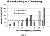
- S17k formulation #1, the S16k formulation, and the S19k formulation were tested for viscosity and conductivity.
- the viscosity was measured on an Ares G2 Rheometer (TA Instruments, New Castle, DE) using recessed concentric cylinders in a forced convection oven cooled with evaporating liquid nitrogen.
- the data in FIG. 1 corresponds to a temperature ramp of 2 °C/min.
- the viscosity of the formulations was quite similar for the range of -20 °C to 25 °C.
- the S16k formulation, which includes an unsaturated tail group of a different weight than the S19k formulations also did not show a marked increase in viscosity around -20 °C (data not shown in FIG. 1 ).
- the marked differences in conductivity between the saturated and unsaturated charge control agents were unexpected because the dominant charge carriers in the electrophoretic medium are the charged pigments, which are loaded at identical levels in all formulations.
- the observed trends in conductivity may be related to the observed changes in viscosity ( FIG. 1 ) because the increased mobility of the pigments may facilitate alignment of the charged particles with instantaneous electric fields associated with the conductivity measurements.
- the differences in conductivity between the electrophoretic medium will influence the stability of a resulting electrophoretic display. Accordingly, the actual loading of unsaturated charge control agent was reduced (as compared to the loading of saturated charge control agents) for the analyses described below. The decreased loading is reflected in Table 1, where the unsaturated CCAs are loaded at about half of the amount of the saturated CCAs.
- DI water (161.5g) was added to a 500mL jacketed reactor held at 25 °C using a circulating, controlled-temperature bath.
- Powdered, acid-processed pig-skin gelatin (10.66g) was hydrated by sprinkling the powdered material onto the surface of the water in the reactor and the suspension was allowed to stand for 0.5hr. The solution stirred for 1hr at 100 rpm.
- Example 1 the temperature was gradually increased from 25 °C to 42.5 °C using a programmable water bath (Huber Ministat 230 with programmable controller).
- the stirring rate was subsequently increased to 300 rpm.
- 162.73g of the internal phase (Example 1) was added to the gelatin solution with a sub-surface addition funnel. The addition was over a period of about one minute.
- the stir rate was increased to 535 rpm, and the solution was stirred for 25min.
- the capsule size distribution (CSD) was then measured, and the stir rate adjusted to achieve a distribution of 20-70 ⁇ m, as desired.
- the resulting encapsulated material was isolated by sedimentation, washed with DI water, and classified by sieving, using sieves of varying mesh size.
- a distribution analysis (Coulter Multisizer) showed that the resulting capsules had a distribution of 30 to 50 ⁇ m with a mean size of ⁇ 40 ⁇ m.
- the encapsulated electrophoretic medium was transformed into a slurry for lamination as described in U.S. Patent No. 8,199,395 .
- the pH was raised above 8.0 with the addition of a 1% ammonium hydroxide solution.
- the capsule slurry was then mixed with a polyurethane binder at a ratio of 1 part by weight binder to 8 parts by weight of capsules.
- a 1% hydroxypropylmethylcellulose (HPMC) in water solution was added as a thickener, with a desired weight fraction of 0.002 HPMC in the slurry.
- Triton X-100 (Sigma-Aldrich) was added as a surfactant, with a desired weight fraction of 0.001.
- the resultant slurry was stirred for one hour.
- the basic slurry was then bar-coated on to a 127 ⁇ m-thick polyester film coated with indium tin oxide (ITO), which will act as an electrode.
- ITO indium tin oxide
- the coated film was oven dried at 60° C for 15 minutes to produce an electrophoretic medium approximately 30 ⁇ m thick containing essentially a single layer of capsules on ITO.
- a front-plane laminate (see U.S. Patent No. 6,982,178 ) was produced by laminating a doped polyurethane adhesive over the capsule layer.
- the front plane laminate was then laminated to a segmented graphite backplane comprising a layer of graphite on a polyester film to produce experimental electro-optic displays suitable for measurement of their electro-optical properties, i.e., as shown in FIGS. 3 and 4 .
- the finished electro-optic displays were equilibrated for five days at a temperature of 25 °C and a relative humidity of 50%.
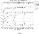
- the electro-optical properties of the displays described in Example 3 were measured using a PR-650 SpectraScan Colorimeter. The samples were driven at various voltages, pulse lengths and temperatures. In these tests, the displays were repeatedly driven to their black and white extreme optical states, then driven to either their black or white extreme optical state. The reflectivity of the optical state was measured about 3 seconds after the final drive pulse (to allow certain transient effects to pass) and then 2 minutes after the final drive pulse, and the two measurements compared to detect any image instability (i.e., lack of bistability in the image). The results are shown in FIG. 3 (in which "DS" refers to dark state and "WS" to white state). The data in FIG. 3 correspond to S17k formulations 2 and 3, which are commercial formulations. The performance of S16k and S19k formulations were similar, however the S19k formulation was generally superior to S16k.
- electrophoretic media including unsaturated charge control agents provide display performance better than electrophoretic media with saturated charge control agents.
- the S19k formulation showed brighter white states, darker dark states, and, thus, a wider dynamic range over a range of temperatures.
- the switching speeds, from a white threshold to a black threshold were faster with formulations including an unsaturated CCA. The increased switching speed was especially evident at low temperatures, e.g., at around 0 °C.
- a 55L* dynamic range could be achieved at 0 °C with a 15V, 500ms drive pulse.
- a 55L* dynamic range could be achieved with a 15V, 240ms drive pulse
- a 60L* dynamic range could be achieved with a 15V, 500ms drive pulse.
- FIG. 4 shows the electro-optic performance of the S16k, S17k #1, and S19k internal phases at -2 °C, 10 °C, and 25 °C across several different pulse lengths. These internal phases were encapsulated at the 500mL scale. As can be seen in FIG. 4 there is a significant difference in dark state performance (filled squares) across all pulse lengths at -2 °C between the unsaturated CCAs (S16k, S19k) and the saturated CCA (S17k).
- the white state performance (filled circles) of the unsaturated CCA formulations is measurably better at longer pulse lengths than the saturated CCA formulations, and about the same at shorted pulse lengths.
- the differences between the unsaturated and saturated CCA formulations are less pronounced at 10 °C, and almost disappear at 25 °C.
- microcell arrays of the type described in U.S. Patent No. 7492505 were prepared, filled with S19k and S17k (formulation #1) electrophoretic media (described in Example 1), and sealed. The arrays were evaluated for optical performance as described above in Example 5. The tests were performed at 20 °C. When driving the microcell displays at 15V for 5 seconds, it was found that the microcell display including the S19k electrophoretic medium had a white state that was about 15% whiter (higher L* value) than the microcell display incorporating the S17k medium. At the same time, the microcell display with the S19k medium exhibited a dark state that was about 15% darker (lower L*) than the S17k formulation.
- the dynamic range of the microcell displays including the S19k also improved by approximately 15% as compared to the microcell displays including the S17k formulation.
- This data suggests that the improved performance of the electrophortetic media with the incorporation of unsaturated charge control agents should not be strongly dependent upon the type of encapsulation used.
Landscapes
- Chemical & Material Sciences (AREA)
- Life Sciences & Earth Sciences (AREA)
- Engineering & Computer Science (AREA)
- Organic Chemistry (AREA)
- Materials Engineering (AREA)
- Molecular Biology (AREA)
- Health & Medical Sciences (AREA)
- Wood Science & Technology (AREA)
- Physics & Mathematics (AREA)
- Chemical Kinetics & Catalysis (AREA)
- Nonlinear Science (AREA)
- General Physics & Mathematics (AREA)
- Optics & Photonics (AREA)
- Electrochemistry (AREA)
- Electrochromic Elements, Electrophoresis, Or Variable Reflection Or Absorption Elements (AREA)
- Compositions Of Macromolecular Compounds (AREA)
Claims (16)
- Elektrophoretisches Medium, umfassend:(a) ein unpolares Fluid;(b) mehrere erste geladene Teilchen und(c) Ladungssteuermittel,wobei das Medium dadurch gekennzeichnet ist, dass die Ladungssteuermittel ein quaternäres Amin und einen ungesättigten polymeren Schwanz, der Monomere mit einer Länge von mindestens 10 Kohlenstoffatomen umfasst, enthält.
- Elektrophoretisches Medium nach Anspruch 1, ferner umfassend mehrere zweite geladene Teilchen, die in dem unpolaren Fluid dispergiert sind, wobei die ersten und die zweiten geladenen Teilchen entgegengesetzte Ladungen aufweisen.
- Elektrophoretisches Medium nach Anspruch 2, wobei die ersten und die zweiten geladenen Teilchen mit den Ladungssteuermitteln komplexiert sind.
- Verkapseltes elektrophoretisches Medium, umfassend das elektrophoretische Medium nach Anspruch 1.
- Verkapseltes elektrophoretisches Medium nach Anspruch 4, wobei das elektrophoretische Medium in einer Mikrozelle oder einem Proteinkoazervat verkapselt ist.
- Elektrophoretisches Medium nach Anspruch 1, wobei das elektrophoretische Medium in einem Polymer dispergiert ist.
- Elektrophoretisches Medium nach Anspruch 1, wobei die Ladungssteuermittel mit den ersten geladenen Teilchen komplexiert, an die ersten geladenen Teilchen adsorbiert oder kovalent an die ersten geladenen Teilchen gebunden sind.
- Elektrophoretisches Medium nach Anspruch 1, wobei der polymere Schwanz Monomere mit einer Länge von mindestens 14 Kohlenstoffatomen und/oder einen Polyester oder einen Poly-sek.-alkohol umfasst.
- Elektrophoretisches Medium nach Anspruch 8, wobei jedes Monomer mindestens eine Kohlenstoff-Kohlenstoff-Doppelbindung umfasst.
- Elektrophoretisches Medium nach Anspruch 1, wobei die ersten geladenen Teilchen Titandioxid, Ruß oder Kupferchromit umfassen.
- Elektrophoretisches Medium nach Anspruch 1, wobei das Verhältnis von Ladungssteuermittel zu ersten geladenen Teilchen größer als 1:500 (Gew./Gew.) ist.
- Elektrophoretisches Medium nach Anspruch 11, wobei die Leitfähigkeit des elektrophoretischen Mediums weniger als 300 pS/m beträgt.
- Elektrophoretisches Medium nach Anspruch 11, wobei die ersten geladenen Teilchen sich in einem Feld von 300 kV/m mit einer Geschwindigkeit von mehr als 50 µm/s bewegen werden, wenn sich das elektrophoretische Medium bei einer Temperatur von 0 °C befindet.
- Elektrophoretisches Medium nach Anspruch 1, ferner umfassend mehrere zweite geladene Teilchen und mehrere dritte geladene Teilchen, wobei die ersten, zweiten oder dritten geladenen Teilchen rot, grün, blau, cyan, gelb oder magenta sind.
- Elektrophoretisches Medium nach Anspruch 1, wobei das mittlere Molekulargewicht des Ladungssteuermittels größer als 12.000 Gramm/mol ist und vorzugsweise zwischen 14.000 Gramm/mol und 22.000 Gramm/mol liegt.
- Frontflächenlaminat, invertiertes Frontflächenlaminat, E-Book-Reader, tragbarer Computer, Tablet-Computer, Mobiltelefon, Smartcard, Schild, Armbanduhr, Regaletikett, Flash-Laufwerk, Fenster oder Fensterfolie, umfassend ein elektrophoretisches Medium nach Anspruch 1.
Priority Applications (1)
| Application Number | Priority Date | Filing Date | Title |
|---|---|---|---|
| PL16854159T PL3359622T3 (pl) | 2015-10-06 | 2016-10-04 | Ulepszone niskotemperaturowe podłoża elektroforetyczne |
Applications Claiming Priority (2)
| Application Number | Priority Date | Filing Date | Title |
|---|---|---|---|
| US201562237691P | 2015-10-06 | 2015-10-06 | |
| PCT/US2016/055294 WO2017062345A1 (en) | 2015-10-06 | 2016-10-04 | Improved low-temperature electrophoretic media |
Publications (3)
| Publication Number | Publication Date |
|---|---|
| EP3359622A1 EP3359622A1 (de) | 2018-08-15 |
| EP3359622A4 EP3359622A4 (de) | 2019-07-31 |
| EP3359622B1 true EP3359622B1 (de) | 2021-01-13 |
Family
ID=58447720
Family Applications (1)
| Application Number | Title | Priority Date | Filing Date |
|---|---|---|---|
| EP16854159.7A Active EP3359622B1 (de) | 2015-10-06 | 2016-10-04 | Verbesserte elektrophoretische medien für niedrige temperaturen |
Country Status (10)
| Country | Link |
|---|---|
| US (3) | US11098206B2 (de) |
| EP (1) | EP3359622B1 (de) |
| JP (1) | JP6552751B2 (de) |
| KR (1) | KR102079884B1 (de) |
| CN (2) | CN111929960B (de) |
| ES (1) | ES2859154T3 (de) |
| PL (1) | PL3359622T3 (de) |
| PT (1) | PT3359622T (de) |
| TW (2) | TWI616493B (de) |
| WO (1) | WO2017062345A1 (de) |
Families Citing this family (18)
| Publication number | Priority date | Publication date | Assignee | Title |
|---|---|---|---|---|
| US10324353B2 (en) | 2013-10-22 | 2019-06-18 | Vlyte Innovations Limited | Wide operating temperature range electrophoretic device |
| CN111929960B (zh) * | 2015-10-06 | 2024-04-23 | 伊英克公司 | 改善的低温电泳介质 |
| KR102329012B1 (ko) * | 2017-06-16 | 2021-11-18 | 이 잉크 코포레이션 | 가변 투과 전기영동 디바이스들 |
| ES2963164T3 (es) * | 2017-06-16 | 2024-03-25 | E Ink Corp | Medios electro-ópticos que incluyen pigmentos encapsulados en aglutinante de gelatina |
| US11460722B2 (en) * | 2019-05-10 | 2022-10-04 | E Ink Corporation | Colored electrophoretic displays |
| WO2020231648A1 (en) * | 2019-05-10 | 2020-11-19 | E Ink Corporation | Charge control agents and particle dispersions including the same |
| GB201914105D0 (en) | 2019-09-30 | 2019-11-13 | Vlyte Innovations Ltd | A see-through electrophoretic device having a visible grid |
| US12181767B2 (en) | 2020-09-15 | 2024-12-31 | E Ink Corporation | Five-particle electrophoretic medium with improved black optical state |
| US11846863B2 (en) | 2020-09-15 | 2023-12-19 | E Ink Corporation | Coordinated top electrode—drive electrode voltages for switching optical state of electrophoretic displays using positive and negative voltages of different magnitudes |
| KR20250048119A (ko) | 2020-09-15 | 2025-04-07 | 이 잉크 코포레이션 | 진보된 컬러 전기영동 디스플레이를 위한 개선된 구동 전압 및 개선된 구동 전압에 의한 디스플레이 |
| US12276894B2 (en) * | 2021-02-04 | 2025-04-15 | E Ink Corporation | Sealing layers comprising a conductive filler for sealing microcells of electrophoretic displays |
| CN118451364A (zh) * | 2022-01-04 | 2024-08-06 | 伊英克公司 | 包括电泳粒子和电荷控制剂组合的电泳介质 |
| EP4578003A1 (de) | 2022-08-25 | 2025-07-02 | E Ink Corporation | Übergangsansteuermodi zum impulsausgleich beim umschalten zwischen globalem farbmodus und direktem aktualisierungsmodus für elektrophoretische anzeigen |
| US20240402562A1 (en) | 2023-06-05 | 2024-12-05 | E Ink Corporation | Color electrophoretic medium having four pigment particle system addressable by waveforms having four voltage levels |
| US12412538B2 (en) | 2023-06-27 | 2025-09-09 | E Ink Corporation | Electrophoretic device with ambient light sensor and adaptive whiteness restoring and color balancing frontlight |
| TWI867636B (zh) * | 2023-07-25 | 2024-12-21 | 美商電子墨水股份有限公司 | 電光組裝件及其所使用的材料 |
| WO2025136446A1 (en) | 2023-12-22 | 2025-06-26 | E Ink Corporation | Five-particle electrophoretic medium with improved black optical state |
| WO2025147410A2 (en) * | 2024-01-02 | 2025-07-10 | E Ink Corporation | Electrophoretic media comprising a cationic charge control agent |
Family Cites Families (159)
| Publication number | Priority date | Publication date | Assignee | Title |
|---|---|---|---|---|
| US2800457A (en) | 1953-06-30 | 1957-07-23 | Ncr Co | Oil-containing microscopic capsules and method of making them |
| US4273672A (en) | 1971-08-23 | 1981-06-16 | Champion International Corporation | Microencapsulation process |
| US4001140A (en) | 1974-07-10 | 1977-01-04 | Ncr Corporation | Capsule manufacture |
| US4219614A (en) | 1977-09-29 | 1980-08-26 | Eastman Kodak Company | Electrophoretic migration imaging composition and process using same |
| US4684596A (en) | 1986-02-18 | 1987-08-04 | Eastman Kodak Company | Electrographic toner and developer composition containing quaternary ammonium salt charge-control agent |
| US5223823A (en) * | 1991-03-11 | 1993-06-29 | Copytele, Inc. | Electrophoretic display panel with plural electrically independent anode elements |
| CA2162874A1 (en) | 1993-05-21 | 1994-12-08 | Wei-Hsin Hou | Methods of preparing electrophoretic dispersions containing two types of particles with different colors and opposite charges |
| US5380362A (en) | 1993-07-16 | 1995-01-10 | Copytele, Inc. | Suspension for use in electrophoretic image display systems |
| DE4332170A1 (de) | 1993-09-22 | 1995-03-23 | Hoechst Ag | Polyestersalze und ihre Verwendung als Ladungssteuermittel |
| US6017584A (en) | 1995-07-20 | 2000-01-25 | E Ink Corporation | Multi-color electrophoretic displays and materials for making the same |
| US7167155B1 (en) | 1995-07-20 | 2007-01-23 | E Ink Corporation | Color electrophoretic displays |
| US7327511B2 (en) | 2004-03-23 | 2008-02-05 | E Ink Corporation | Light modulators |
| US8139050B2 (en) | 1995-07-20 | 2012-03-20 | E Ink Corporation | Addressing schemes for electronic displays |
| US7956841B2 (en) | 1995-07-20 | 2011-06-07 | E Ink Corporation | Stylus-based addressing structures for displays |
| US8089453B2 (en) | 1995-07-20 | 2012-01-03 | E Ink Corporation | Stylus-based addressing structures for displays |
| US7259744B2 (en) | 1995-07-20 | 2007-08-21 | E Ink Corporation | Dielectrophoretic displays |
| US6866760B2 (en) | 1998-08-27 | 2005-03-15 | E Ink Corporation | Electrophoretic medium and process for the production thereof |
| US7411719B2 (en) | 1995-07-20 | 2008-08-12 | E Ink Corporation | Electrophoretic medium and process for the production thereof |
| US7023420B2 (en) | 2000-11-29 | 2006-04-04 | E Ink Corporation | Electronic display with photo-addressing means |
| US7193625B2 (en) | 1999-04-30 | 2007-03-20 | E Ink Corporation | Methods for driving electro-optic displays, and apparatus for use therein |
| US7583251B2 (en) | 1995-07-20 | 2009-09-01 | E Ink Corporation | Dielectrophoretic displays |
| US6664944B1 (en) | 1995-07-20 | 2003-12-16 | E-Ink Corporation | Rear electrode structures for electrophoretic displays |
| US7999787B2 (en) | 1995-07-20 | 2011-08-16 | E Ink Corporation | Methods for driving electrophoretic displays using dielectrophoretic forces |
| US5930026A (en) | 1996-10-25 | 1999-07-27 | Massachusetts Institute Of Technology | Nonemissive displays and piezoelectric power supplies therefor |
| US8213076B2 (en) | 1997-08-28 | 2012-07-03 | E Ink Corporation | Multi-color electrophoretic displays and materials for making the same |
| US7002728B2 (en) | 1997-08-28 | 2006-02-21 | E Ink Corporation | Electrophoretic particles, and processes for the production thereof |
| US6839158B2 (en) | 1997-08-28 | 2005-01-04 | E Ink Corporation | Encapsulated electrophoretic displays having a monolayer of capsules and materials and methods for making the same |
| US8040594B2 (en) | 1997-08-28 | 2011-10-18 | E Ink Corporation | Multi-color electrophoretic displays |
| US6753999B2 (en) | 1998-03-18 | 2004-06-22 | E Ink Corporation | Electrophoretic displays in portable devices and systems for addressing such displays |
| AU3190499A (en) | 1998-03-18 | 1999-10-11 | E-Ink Corporation | Electrophoretic displays and systems for addressing such displays |
| US7075502B1 (en) | 1998-04-10 | 2006-07-11 | E Ink Corporation | Full color reflective display with multichromatic sub-pixels |
| US6241921B1 (en) | 1998-05-15 | 2001-06-05 | Massachusetts Institute Of Technology | Heterogeneous display elements and methods for their fabrication |
| EP1093600B1 (de) | 1998-07-08 | 2004-09-15 | E Ink Corporation | Verfahren zur verbesserung der farbwiedergabe in elektrophoretischen vorrichtungen, welche mikrokapseln verwenden |
| WO2000003349A1 (en) | 1998-07-08 | 2000-01-20 | E Ink Corporation | Method and apparatus for sensing the state of an electrophoretic display |
| US20030102858A1 (en) | 1998-07-08 | 2003-06-05 | E Ink Corporation | Method and apparatus for determining properties of an electrophoretic display |
| US6504524B1 (en) | 2000-03-08 | 2003-01-07 | E Ink Corporation | Addressing methods for displays having zero time-average field |
| US6531997B1 (en) | 1999-04-30 | 2003-03-11 | E Ink Corporation | Methods for addressing electrophoretic displays |
| US7012600B2 (en) | 1999-04-30 | 2006-03-14 | E Ink Corporation | Methods for driving bistable electro-optic displays, and apparatus for use therein |
| US7119772B2 (en) | 1999-04-30 | 2006-10-10 | E Ink Corporation | Methods for driving bistable electro-optic displays, and apparatus for use therein |
| US8009348B2 (en) | 1999-05-03 | 2011-08-30 | E Ink Corporation | Machine-readable displays |
| US20010039879A1 (en) | 1999-12-16 | 2001-11-15 | Chapman Rick L. | Charged filter media containing charge control agents |
| US6672921B1 (en) | 2000-03-03 | 2004-01-06 | Sipix Imaging, Inc. | Manufacturing process for electrophoretic display |
| US6930818B1 (en) | 2000-03-03 | 2005-08-16 | Sipix Imaging, Inc. | Electrophoretic display and novel process for its manufacture |
| US6788449B2 (en) | 2000-03-03 | 2004-09-07 | Sipix Imaging, Inc. | Electrophoretic display and novel process for its manufacture |
| AU2002250304A1 (en) | 2001-03-13 | 2002-09-24 | E Ink Corporation | Apparatus for displaying drawings |
| US20050156340A1 (en) | 2004-01-20 | 2005-07-21 | E Ink Corporation | Preparation of capsules |
| US7679814B2 (en) | 2001-04-02 | 2010-03-16 | E Ink Corporation | Materials for use in electrophoretic displays |
| US7230750B2 (en) * | 2001-05-15 | 2007-06-12 | E Ink Corporation | Electrophoretic media and processes for the production thereof |
| EP1666964B1 (de) | 2001-04-02 | 2018-12-19 | E Ink Corporation | Elektrophoretisches Medium mit verbesserter Bildstabilität |
| JP4188091B2 (ja) | 2001-05-15 | 2008-11-26 | イー インク コーポレイション | 電気泳動粒子 |
| US6727873B2 (en) | 2001-05-18 | 2004-04-27 | International Business Machines Corporation | Reflective electrophoretic display with stacked color cells |
| US7535624B2 (en) | 2001-07-09 | 2009-05-19 | E Ink Corporation | Electro-optic display and materials for use therein |
| US6982178B2 (en) | 2002-06-10 | 2006-01-03 | E Ink Corporation | Components and methods for use in electro-optic displays |
| US7492505B2 (en) | 2001-08-17 | 2009-02-17 | Sipix Imaging, Inc. | Electrophoretic display with dual mode switching |
| US6825970B2 (en) | 2001-09-14 | 2004-11-30 | E Ink Corporation | Methods for addressing electro-optic materials |
| US7528822B2 (en) | 2001-11-20 | 2009-05-05 | E Ink Corporation | Methods for driving electro-optic displays |
| US8558783B2 (en) | 2001-11-20 | 2013-10-15 | E Ink Corporation | Electro-optic displays with reduced remnant voltage |
| US7952557B2 (en) | 2001-11-20 | 2011-05-31 | E Ink Corporation | Methods and apparatus for driving electro-optic displays |
| US8125501B2 (en) | 2001-11-20 | 2012-02-28 | E Ink Corporation | Voltage modulated driver circuits for electro-optic displays |
| US7202847B2 (en) | 2002-06-28 | 2007-04-10 | E Ink Corporation | Voltage modulated driver circuits for electro-optic displays |
| US9412314B2 (en) | 2001-11-20 | 2016-08-09 | E Ink Corporation | Methods for driving electro-optic displays |
| US6905807B2 (en) | 2002-01-08 | 2005-06-14 | Samsung Electronics Co., Ltd. | Liquid inks comprising stabilizing organosols |
| US6574034B1 (en) * | 2002-01-16 | 2003-06-03 | Xerox Corporation | Electrophoretic displays, display fluids for use therein, and methods of displaying images |
| US6900851B2 (en) | 2002-02-08 | 2005-05-31 | E Ink Corporation | Electro-optic displays and optical systems for addressing such displays |
| CN100339757C (zh) | 2002-03-06 | 2007-09-26 | 株式会社普利司通 | 图像显示装置和方法 |
| US6950220B2 (en) | 2002-03-18 | 2005-09-27 | E Ink Corporation | Electro-optic displays, and methods for driving same |
| WO2003092077A2 (en) | 2002-04-24 | 2003-11-06 | E Ink Corporation | Electronic displays |
| US8363299B2 (en) | 2002-06-10 | 2013-01-29 | E Ink Corporation | Electro-optic displays, and processes for the production thereof |
| US20110199671A1 (en) | 2002-06-13 | 2011-08-18 | E Ink Corporation | Methods for driving electrophoretic displays using dielectrophoretic forces |
| US20080024482A1 (en) | 2002-06-13 | 2008-01-31 | E Ink Corporation | Methods for driving electro-optic displays |
| US7839564B2 (en) | 2002-09-03 | 2010-11-23 | E Ink Corporation | Components and methods for use in electro-optic displays |
| CN101109885B (zh) | 2002-09-03 | 2012-06-13 | 伊英克公司 | 电光显示器 |
| JP2006510066A (ja) | 2002-12-16 | 2006-03-23 | イー−インク コーポレイション | 電気光学表示装置用バックプレーン |
| US6922276B2 (en) | 2002-12-23 | 2005-07-26 | E Ink Corporation | Flexible electro-optic displays |
| US7339715B2 (en) | 2003-03-25 | 2008-03-04 | E Ink Corporation | Processes for the production of electrophoretic displays |
| US7910175B2 (en) | 2003-03-25 | 2011-03-22 | E Ink Corporation | Processes for the production of electrophoretic displays |
| US9672766B2 (en) | 2003-03-31 | 2017-06-06 | E Ink Corporation | Methods for driving electro-optic displays |
| US7236291B2 (en) | 2003-04-02 | 2007-06-26 | Bridgestone Corporation | Particle use for image display media, image display panel using the particles, and image display device |
| US8174490B2 (en) | 2003-06-30 | 2012-05-08 | E Ink Corporation | Methods for driving electrophoretic displays |
| EP1656658A4 (de) | 2003-08-19 | 2009-12-30 | E Ink Corp | Verfahren zur steuerung von elektrooptischen displays |
| WO2005029458A1 (en) | 2003-09-19 | 2005-03-31 | E Ink Corporation | Methods for reducing edge effects in electro-optic displays |
| US8300006B2 (en) | 2003-10-03 | 2012-10-30 | E Ink Corporation | Electrophoretic display unit |
| JP4848280B2 (ja) * | 2003-10-08 | 2011-12-28 | イー インク コーポレイション | 電気泳動媒質 |
| CN100434959C (zh) * | 2003-10-08 | 2008-11-19 | 伊英克公司 | 电泳介质 |
| US8319759B2 (en) | 2003-10-08 | 2012-11-27 | E Ink Corporation | Electrowetting displays |
| US7420549B2 (en) | 2003-10-08 | 2008-09-02 | E Ink Corporation | Electro-wetting displays |
| CN101382719B (zh) * | 2003-10-24 | 2012-04-04 | 伊英克公司 | 电光显示器 |
| WO2005052905A1 (en) | 2003-11-25 | 2005-06-09 | Koninklijke Philips Electronics N.V. | A display apparatus with a display device and a cyclic rail-stabilized method of driving the display device |
| US8928562B2 (en) | 2003-11-25 | 2015-01-06 | E Ink Corporation | Electro-optic displays, and methods for driving same |
| US7492339B2 (en) | 2004-03-26 | 2009-02-17 | E Ink Corporation | Methods for driving bistable electro-optic displays |
| US8289250B2 (en) | 2004-03-31 | 2012-10-16 | E Ink Corporation | Methods for driving electro-optic displays |
| US20050253777A1 (en) | 2004-05-12 | 2005-11-17 | E Ink Corporation | Tiled displays and methods for driving same |
| WO2006015044A1 (en) | 2004-07-27 | 2006-02-09 | E Ink Corporation | Electro-optic displays |
| US20080136774A1 (en) | 2004-07-27 | 2008-06-12 | E Ink Corporation | Methods for driving electrophoretic displays using dielectrophoretic forces |
| US7453445B2 (en) | 2004-08-13 | 2008-11-18 | E Ink Corproation | Methods for driving electro-optic displays |
| JP4718859B2 (ja) | 2005-02-17 | 2011-07-06 | セイコーエプソン株式会社 | 電気泳動装置とその駆動方法、及び電子機器 |
| JP4690079B2 (ja) | 2005-03-04 | 2011-06-01 | セイコーエプソン株式会社 | 電気泳動装置とその駆動方法、及び電子機器 |
| JP2007041300A (ja) | 2005-08-03 | 2007-02-15 | Fuji Xerox Co Ltd | 画像処理装置、画像処理方法、及び画像処理プログラム |
| US20080043318A1 (en) | 2005-10-18 | 2008-02-21 | E Ink Corporation | Color electro-optic displays, and processes for the production thereof |
| JP4946016B2 (ja) | 2005-11-25 | 2012-06-06 | 富士ゼロックス株式会社 | 多色表示用光学組成物、光学素子、及び光学素子の表示方法 |
| US7952790B2 (en) | 2006-03-22 | 2011-05-31 | E Ink Corporation | Electro-optic media produced using ink jet printing |
| US8018640B2 (en) | 2006-07-13 | 2011-09-13 | E Ink Corporation | Particles for use in electrophoretic displays |
| US20080024429A1 (en) | 2006-07-25 | 2008-01-31 | E Ink Corporation | Electrophoretic displays using gaseous fluids |
| JP2008068429A (ja) | 2006-09-12 | 2008-03-27 | Fuji Xerox Co Ltd | 記録装置 |
| EP2122412A2 (de) | 2006-11-30 | 2009-11-25 | Koninklijke Philips Electronics N.V. | Auf gleicher ebene wechselnde elektrophoretische farbanzeige |
| JP2008145879A (ja) * | 2006-12-12 | 2008-06-26 | Ricoh Co Ltd | ポリマーグラフト微粒子、その製造方法、電気泳動分散液及びこれを利用した画像表示装置 |
| US7499211B2 (en) | 2006-12-26 | 2009-03-03 | Fuji Xerox Co., Ltd. | Display medium and display device |
| CN101681211A (zh) | 2007-05-21 | 2010-03-24 | 伊英克公司 | 用于驱动视频电光显示器的方法 |
| US8174491B2 (en) | 2007-06-05 | 2012-05-08 | Fuji Xerox Co., Ltd. | Image display medium and image display device |
| US9199441B2 (en) | 2007-06-28 | 2015-12-01 | E Ink Corporation | Processes for the production of electro-optic displays, and color filters for use therein |
| US8902153B2 (en) | 2007-08-03 | 2014-12-02 | E Ink Corporation | Electro-optic displays, and processes for their production |
| JP5083095B2 (ja) | 2007-08-10 | 2012-11-28 | 富士ゼロックス株式会社 | 画像表示媒体及び画像表示装置 |
| EP2053099B1 (de) * | 2007-10-24 | 2010-12-15 | Agfa Graphics N.V. | Weisse Tintenstrahldruckfarbe mit verbesserter Dispersionsstabilität |
| US8054526B2 (en) | 2008-03-21 | 2011-11-08 | E Ink Corporation | Electro-optic displays, and color filters for use therein |
| US8314784B2 (en) | 2008-04-11 | 2012-11-20 | E Ink Corporation | Methods for driving electro-optic displays |
| JP5310145B2 (ja) * | 2008-08-20 | 2013-10-09 | 株式会社リコー | 電気泳動液、及びそれを用いた表示素子 |
| JP5689320B2 (ja) | 2008-12-16 | 2015-03-25 | 昭和電工株式会社 | 硬化性組成物及びその硬化物 |
| US8717664B2 (en) | 2012-10-02 | 2014-05-06 | Sipix Imaging, Inc. | Color display device |
| US8964282B2 (en) | 2012-10-02 | 2015-02-24 | E Ink California, Llc | Color display device |
| TWI484273B (zh) * | 2009-02-09 | 2015-05-11 | E Ink Corp | 電泳粒子 |
| US8098418B2 (en) | 2009-03-03 | 2012-01-17 | E. Ink Corporation | Electro-optic displays, and color filters for use therein |
| US9657114B2 (en) | 2009-07-31 | 2017-05-23 | Hewlett-Packard Development Company, L.P. | Electrically chargeable encapsulated particles |
| WO2011046563A1 (en) | 2009-10-16 | 2011-04-21 | Hewlett Packard Development Company, L.P. | Electronic inks |
| KR101330269B1 (ko) * | 2009-11-20 | 2013-11-18 | 한국전자통신연구원 | 전자 잉크의 제조 방법, 이에 의해 형성된 전자잉크 및 이를 포함하는 전기영동 디스플레이 |
| JP2011123205A (ja) | 2009-12-09 | 2011-06-23 | Fuji Xerox Co Ltd | 表示装置 |
| WO2011078854A1 (en) | 2009-12-22 | 2011-06-30 | Hewlett-Packard Development Company | Ink composition and method of preparing same |
| JP5381737B2 (ja) | 2010-01-18 | 2014-01-08 | 富士ゼロックス株式会社 | 表示装置 |
| TWI504692B (zh) * | 2010-04-05 | 2015-10-21 | Sipix Imaging Inc | 用於電泳顯示器之顏料顆粒 |
| CN102834857B (zh) | 2010-04-09 | 2016-03-02 | 伊英克公司 | 用于驱动电光显示器的方法 |
| TWI484275B (zh) | 2010-05-21 | 2015-05-11 | E Ink Corp | 光電顯示器及其驅動方法、微型空腔電泳顯示器 |
| US9116412B2 (en) | 2010-05-26 | 2015-08-25 | E Ink California, Llc | Color display architecture and driving methods |
| US8576470B2 (en) | 2010-06-02 | 2013-11-05 | E Ink Corporation | Electro-optic displays, and color alters for use therein |
| JP5434804B2 (ja) | 2010-06-07 | 2014-03-05 | 富士ゼロックス株式会社 | 表示媒体の駆動装置、駆動プログラム、及び表示装置 |
| US8496324B2 (en) | 2010-07-30 | 2013-07-30 | Hewlett-Packard Development Company, L.P. | Ink composition, digital printing system and methods |
| WO2012074792A1 (en) | 2010-11-30 | 2012-06-07 | E Ink Corporation | Multi-color electrophoretic displays |
| JP5304850B2 (ja) | 2010-12-01 | 2013-10-02 | 富士ゼロックス株式会社 | 表示媒体の駆動装置、駆動プログラム、及び表示装置 |
| US8449096B2 (en) | 2010-12-06 | 2013-05-28 | Xerox Corporation | Five member ring stabilizers for quinacridone-type pigments in solid ink |
| TWM411262U (en) | 2010-12-17 | 2011-09-11 | dun-ji Fu | Inner container structure of striking bag |
| CN102591086B (zh) * | 2011-01-04 | 2016-02-10 | 广州奥熠电子科技有限公司 | 一种电泳显示液及其粒子制备方法 |
| JP2012198417A (ja) | 2011-03-22 | 2012-10-18 | Sony Corp | 電気泳動素子、表示装置および電子機器 |
| US8873129B2 (en) | 2011-04-07 | 2014-10-28 | E Ink Corporation | Tetrachromatic color filter array for reflective display |
| CN103688212B (zh) | 2011-05-21 | 2017-11-28 | 伊英克公司 | 电光显示器 |
| US9382427B2 (en) * | 2011-06-09 | 2016-07-05 | E Ink California, Llc | Silane-containing pigment particles for electrophoretic display |
| US20120320308A1 (en) * | 2011-06-20 | 2012-12-20 | Jong-Souk Yeo | Transflective displays |
| US8587859B2 (en) | 2011-06-23 | 2013-11-19 | Fuji Xerox Co., Ltd. | White particle for display, particle dispersion for display , display medium, and display device |
| US8652245B2 (en) | 2011-09-15 | 2014-02-18 | Hewlett-Packard Development Company, L.P. | Dual color electronically addressable ink |
| EP3783597A1 (de) | 2012-02-01 | 2021-02-24 | E Ink Corporation | Verfahren zur ansteuerung elektrooptischer anzeigen |
| US8917439B2 (en) | 2012-02-09 | 2014-12-23 | E Ink California, Llc | Shutter mode for color display devices |
| US20130222884A1 (en) | 2012-02-27 | 2013-08-29 | Fujifilm Corporation | Electrophoretic particle, particle dispersion liquid for display, display medium and display device |
| JP5981729B2 (ja) | 2012-02-27 | 2016-08-31 | イー インク コーポレイション | 電気泳動粒子、電気泳動粒子分散液、表示媒体、及び表示装置 |
| JP2013174819A (ja) | 2012-02-27 | 2013-09-05 | Fuji Xerox Co Ltd | 電気泳動粒子、電気泳動粒子分散液、表示媒体、及び表示装置 |
| JP5972604B2 (ja) | 2012-02-27 | 2016-08-17 | イー インク コーポレイション | 電気泳動表示用分散液、表示媒体、及び表示装置 |
| JP2013173896A (ja) | 2012-02-27 | 2013-09-05 | Fuji Xerox Co Ltd | 表示用分散液、表示媒体、および表示装置 |
| WO2013189580A1 (en) * | 2012-06-22 | 2013-12-27 | Merck Patent Gmbh | Electrophoretic fluid |
| JP5884659B2 (ja) | 2012-06-29 | 2016-03-15 | ソニー株式会社 | 電気泳動素子および表示装置 |
| JP6008685B2 (ja) | 2012-10-12 | 2016-10-19 | イー インク コーポレイション | 表示用粒子分散液、表示媒体、及び表示装置 |
| WO2014186449A1 (en) * | 2013-05-14 | 2014-11-20 | E Ink Corporation | Colored electrophoretic displays |
| US9922603B2 (en) * | 2014-07-09 | 2018-03-20 | E Ink California, Llc | Color display device and driving methods therefor |
| CN111929960B (zh) * | 2015-10-06 | 2024-04-23 | 伊英克公司 | 改善的低温电泳介质 |
-
2016
- 2016-10-04 CN CN202010894564.XA patent/CN111929960B/zh active Active
- 2016-10-04 WO PCT/US2016/055294 patent/WO2017062345A1/en not_active Ceased
- 2016-10-04 PL PL16854159T patent/PL3359622T3/pl unknown
- 2016-10-04 JP JP2018536709A patent/JP6552751B2/ja active Active
- 2016-10-04 CN CN201680057982.5A patent/CN108138038B/zh active Active
- 2016-10-04 EP EP16854159.7A patent/EP3359622B1/de active Active
- 2016-10-04 PT PT168541597T patent/PT3359622T/pt unknown
- 2016-10-04 US US15/284,887 patent/US11098206B2/en active Active
- 2016-10-04 KR KR1020187009768A patent/KR102079884B1/ko active Active
- 2016-10-04 ES ES16854159T patent/ES2859154T3/es active Active
- 2016-10-05 TW TW105132197A patent/TWI616493B/zh active
- 2016-10-05 TW TW106144725A patent/TWI665266B/zh active
-
2021
- 2021-07-21 US US17/381,983 patent/US12084595B2/en active Active
-
2024
- 2024-08-02 US US18/792,794 patent/US12606713B2/en active Active
Non-Patent Citations (1)
| Title |
|---|
| None * |
Also Published As
| Publication number | Publication date |
|---|---|
| EP3359622A1 (de) | 2018-08-15 |
| KR20180039186A (ko) | 2018-04-17 |
| CN108138038B (zh) | 2020-10-09 |
| CN108138038A (zh) | 2018-06-08 |
| KR102079884B1 (ko) | 2020-02-20 |
| TWI616493B (zh) | 2018-03-01 |
| US20170097556A1 (en) | 2017-04-06 |
| US20240392144A1 (en) | 2024-11-28 |
| US12606713B2 (en) | 2026-04-21 |
| TW201829646A (zh) | 2018-08-16 |
| US12084595B2 (en) | 2024-09-10 |
| HK1249127A1 (zh) | 2018-10-26 |
| WO2017062345A1 (en) | 2017-04-13 |
| US20210355332A1 (en) | 2021-11-18 |
| CN111929960A (zh) | 2020-11-13 |
| EP3359622A4 (de) | 2019-07-31 |
| CN111929960B (zh) | 2024-04-23 |
| TW201718777A (zh) | 2017-06-01 |
| JP6552751B2 (ja) | 2019-07-31 |
| PT3359622T (pt) | 2021-03-04 |
| ES2859154T3 (es) | 2021-10-01 |
| TWI665266B (zh) | 2019-07-11 |
| JP2018536904A (ja) | 2018-12-13 |
| US11098206B2 (en) | 2021-08-24 |
| PL3359622T3 (pl) | 2021-07-05 |
Similar Documents
| Publication | Publication Date | Title |
|---|---|---|
| US12606713B2 (en) | Electrophoretic media including charge control agents comprising quartenary amines and unsaturated polymeric tails | |
| US9765015B2 (en) | Branched polyol additives for electrophoretic media | |
| US10061123B2 (en) | Surfactants for improving electrophoretic media performance | |
| EP3583464B1 (de) | Für elektrophoretische farbanzeigemedien verwendete polymeradditive | |
| US20170205649A1 (en) | Polyhydroxy compositions for sealing electrophoretic displays | |
| WO2020231648A1 (en) | Charge control agents and particle dispersions including the same | |
| US10585325B2 (en) | Photo-thermally induced polymerization inhibitors for electrophoretic media | |
| HK40031437A (en) | Improved low-temperature electrophoretic media | |
| HK40031437B (zh) | 改善的低温电泳介质 | |
| HK1249127B (zh) | 改善的低温电泳介质 |
Legal Events
| Date | Code | Title | Description |
|---|---|---|---|
| STAA | Information on the status of an ep patent application or granted ep patent |
Free format text: STATUS: THE INTERNATIONAL PUBLICATION HAS BEEN MADE |
|
| PUAI | Public reference made under article 153(3) epc to a published international application that has entered the european phase |
Free format text: ORIGINAL CODE: 0009012 |
|
| STAA | Information on the status of an ep patent application or granted ep patent |
Free format text: STATUS: REQUEST FOR EXAMINATION WAS MADE |
|
| 17P | Request for examination filed |
Effective date: 20180507 |
|
| AK | Designated contracting states |
Kind code of ref document: A1 Designated state(s): AL AT BE BG CH CY CZ DE DK EE ES FI FR GB GR HR HU IE IS IT LI LT LU LV MC MK MT NL NO PL PT RO RS SE SI SK SM TR |
|
| AX | Request for extension of the european patent |
Extension state: BA ME |
|
| DAV | Request for validation of the european patent (deleted) | ||
| DAX | Request for extension of the european patent (deleted) | ||
| A4 | Supplementary search report drawn up and despatched |
Effective date: 20190701 |
|
| RIC1 | Information provided on ipc code assigned before grant |
Ipc: G02F 1/15 20190101ALI20190625BHEP Ipc: C09K 3/00 20060101ALI20190625BHEP Ipc: C09K 11/02 20060101AFI20190625BHEP |
|
| STAA | Information on the status of an ep patent application or granted ep patent |
Free format text: STATUS: EXAMINATION IS IN PROGRESS |
|
| 17Q | First examination report despatched |
Effective date: 20200218 |
|
| GRAP | Despatch of communication of intention to grant a patent |
Free format text: ORIGINAL CODE: EPIDOSNIGR1 |
|
| STAA | Information on the status of an ep patent application or granted ep patent |
Free format text: STATUS: GRANT OF PATENT IS INTENDED |
|
| INTG | Intention to grant announced |
Effective date: 20200928 |
|
| GRAS | Grant fee paid |
Free format text: ORIGINAL CODE: EPIDOSNIGR3 |
|
| GRAA | (expected) grant |
Free format text: ORIGINAL CODE: 0009210 |
|
| STAA | Information on the status of an ep patent application or granted ep patent |
Free format text: STATUS: THE PATENT HAS BEEN GRANTED |
|
| AK | Designated contracting states |
Kind code of ref document: B1 Designated state(s): AL AT BE BG CH CY CZ DE DK EE ES FI FR GB GR HR HU IE IS IT LI LT LU LV MC MK MT NL NO PL PT RO RS SE SI SK SM TR |
|
| REG | Reference to a national code |
Ref country code: GB Ref legal event code: FG4D |
|
| REG | Reference to a national code |
Ref country code: CH Ref legal event code: EP |
|
| REG | Reference to a national code |
Ref country code: IE Ref legal event code: FG4D |
|
| REG | Reference to a national code |
Ref country code: DE Ref legal event code: R096 Ref document number: 602016051508 Country of ref document: DE |
|
| REG | Reference to a national code |
Ref country code: AT Ref legal event code: REF Ref document number: 1354560 Country of ref document: AT Kind code of ref document: T Effective date: 20210215 |
|
| REG | Reference to a national code |
Ref country code: PT Ref legal event code: SC4A Ref document number: 3359622 Country of ref document: PT Date of ref document: 20210304 Kind code of ref document: T Free format text: AVAILABILITY OF NATIONAL TRANSLATION Effective date: 20210225 |
|
| REG | Reference to a national code |
Ref country code: SE Ref legal event code: TRGR |
|
| REG | Reference to a national code |
Ref country code: NL Ref legal event code: FP |
|
| REG | Reference to a national code |
Ref country code: NO Ref legal event code: T2 Effective date: 20210113 |
|
| REG | Reference to a national code |
Ref country code: LT Ref legal event code: MG9D |
|
| PG25 | Lapsed in a contracting state [announced via postgrant information from national office to epo] |
Ref country code: HR Free format text: LAPSE BECAUSE OF FAILURE TO SUBMIT A TRANSLATION OF THE DESCRIPTION OR TO PAY THE FEE WITHIN THE PRESCRIBED TIME-LIMIT Effective date: 20210113 Ref country code: FI Free format text: LAPSE BECAUSE OF FAILURE TO SUBMIT A TRANSLATION OF THE DESCRIPTION OR TO PAY THE FEE WITHIN THE PRESCRIBED TIME-LIMIT Effective date: 20210113 Ref country code: GR Free format text: LAPSE BECAUSE OF FAILURE TO SUBMIT A TRANSLATION OF THE DESCRIPTION OR TO PAY THE FEE WITHIN THE PRESCRIBED TIME-LIMIT Effective date: 20210414 Ref country code: BG Free format text: LAPSE BECAUSE OF FAILURE TO SUBMIT A TRANSLATION OF THE DESCRIPTION OR TO PAY THE FEE WITHIN THE PRESCRIBED TIME-LIMIT Effective date: 20210413 Ref country code: LT Free format text: LAPSE BECAUSE OF FAILURE TO SUBMIT A TRANSLATION OF THE DESCRIPTION OR TO PAY THE FEE WITHIN THE PRESCRIBED TIME-LIMIT Effective date: 20210113 |
|
| PG25 | Lapsed in a contracting state [announced via postgrant information from national office to epo] |
Ref country code: LV Free format text: LAPSE BECAUSE OF FAILURE TO SUBMIT A TRANSLATION OF THE DESCRIPTION OR TO PAY THE FEE WITHIN THE PRESCRIBED TIME-LIMIT Effective date: 20210113 Ref country code: RS Free format text: LAPSE BECAUSE OF FAILURE TO SUBMIT A TRANSLATION OF THE DESCRIPTION OR TO PAY THE FEE WITHIN THE PRESCRIBED TIME-LIMIT Effective date: 20210113 |
|
| PG25 | Lapsed in a contracting state [announced via postgrant information from national office to epo] |
Ref country code: IS Free format text: LAPSE BECAUSE OF FAILURE TO SUBMIT A TRANSLATION OF THE DESCRIPTION OR TO PAY THE FEE WITHIN THE PRESCRIBED TIME-LIMIT Effective date: 20210513 |
|
| REG | Reference to a national code |
Ref country code: ES Ref legal event code: FG2A Ref document number: 2859154 Country of ref document: ES Kind code of ref document: T3 Effective date: 20211001 |
|
| REG | Reference to a national code |
Ref country code: DE Ref legal event code: R097 Ref document number: 602016051508 Country of ref document: DE |
|
| REG | Reference to a national code |
Ref country code: AT Ref legal event code: UEP Ref document number: 1354560 Country of ref document: AT Kind code of ref document: T Effective date: 20210113 |
|
| PG25 | Lapsed in a contracting state [announced via postgrant information from national office to epo] |
Ref country code: SM Free format text: LAPSE BECAUSE OF FAILURE TO SUBMIT A TRANSLATION OF THE DESCRIPTION OR TO PAY THE FEE WITHIN THE PRESCRIBED TIME-LIMIT Effective date: 20210113 Ref country code: EE Free format text: LAPSE BECAUSE OF FAILURE TO SUBMIT A TRANSLATION OF THE DESCRIPTION OR TO PAY THE FEE WITHIN THE PRESCRIBED TIME-LIMIT Effective date: 20210113 Ref country code: CZ Free format text: LAPSE BECAUSE OF FAILURE TO SUBMIT A TRANSLATION OF THE DESCRIPTION OR TO PAY THE FEE WITHIN THE PRESCRIBED TIME-LIMIT Effective date: 20210113 |
|
| PLBE | No opposition filed within time limit |
Free format text: ORIGINAL CODE: 0009261 |
|
| STAA | Information on the status of an ep patent application or granted ep patent |
Free format text: STATUS: NO OPPOSITION FILED WITHIN TIME LIMIT |
|
| PG25 | Lapsed in a contracting state [announced via postgrant information from national office to epo] |
Ref country code: SK Free format text: LAPSE BECAUSE OF FAILURE TO SUBMIT A TRANSLATION OF THE DESCRIPTION OR TO PAY THE FEE WITHIN THE PRESCRIBED TIME-LIMIT Effective date: 20210113 Ref country code: RO Free format text: LAPSE BECAUSE OF FAILURE TO SUBMIT A TRANSLATION OF THE DESCRIPTION OR TO PAY THE FEE WITHIN THE PRESCRIBED TIME-LIMIT Effective date: 20210113 Ref country code: DK Free format text: LAPSE BECAUSE OF FAILURE TO SUBMIT A TRANSLATION OF THE DESCRIPTION OR TO PAY THE FEE WITHIN THE PRESCRIBED TIME-LIMIT Effective date: 20210113 |
|
| 26N | No opposition filed |
Effective date: 20211014 |
|
| PG25 | Lapsed in a contracting state [announced via postgrant information from national office to epo] |
Ref country code: AL Free format text: LAPSE BECAUSE OF FAILURE TO SUBMIT A TRANSLATION OF THE DESCRIPTION OR TO PAY THE FEE WITHIN THE PRESCRIBED TIME-LIMIT Effective date: 20210113 |
|
| PG25 | Lapsed in a contracting state [announced via postgrant information from national office to epo] |
Ref country code: SI Free format text: LAPSE BECAUSE OF FAILURE TO SUBMIT A TRANSLATION OF THE DESCRIPTION OR TO PAY THE FEE WITHIN THE PRESCRIBED TIME-LIMIT Effective date: 20210113 |
|
| PG25 | Lapsed in a contracting state [announced via postgrant information from national office to epo] |
Ref country code: IS Free format text: LAPSE BECAUSE OF FAILURE TO SUBMIT A TRANSLATION OF THE DESCRIPTION OR TO PAY THE FEE WITHIN THE PRESCRIBED TIME-LIMIT Effective date: 20210513 |
|
| PG25 | Lapsed in a contracting state [announced via postgrant information from national office to epo] |
Ref country code: MC Free format text: LAPSE BECAUSE OF FAILURE TO SUBMIT A TRANSLATION OF THE DESCRIPTION OR TO PAY THE FEE WITHIN THE PRESCRIBED TIME-LIMIT Effective date: 20210113 |
|
| PG25 | Lapsed in a contracting state [announced via postgrant information from national office to epo] |
Ref country code: LU Free format text: LAPSE BECAUSE OF NON-PAYMENT OF DUE FEES Effective date: 20211004 |
|
| PG25 | Lapsed in a contracting state [announced via postgrant information from national office to epo] |
Ref country code: HU Free format text: LAPSE BECAUSE OF FAILURE TO SUBMIT A TRANSLATION OF THE DESCRIPTION OR TO PAY THE FEE WITHIN THE PRESCRIBED TIME-LIMIT; INVALID AB INITIO Effective date: 20161004 |
|
| PG25 | Lapsed in a contracting state [announced via postgrant information from national office to epo] |
Ref country code: CY Free format text: LAPSE BECAUSE OF FAILURE TO SUBMIT A TRANSLATION OF THE DESCRIPTION OR TO PAY THE FEE WITHIN THE PRESCRIBED TIME-LIMIT Effective date: 20210113 |
|
| PG25 | Lapsed in a contracting state [announced via postgrant information from national office to epo] |
Ref country code: MK Free format text: LAPSE BECAUSE OF FAILURE TO SUBMIT A TRANSLATION OF THE DESCRIPTION OR TO PAY THE FEE WITHIN THE PRESCRIBED TIME-LIMIT Effective date: 20210113 |
|
| PG25 | Lapsed in a contracting state [announced via postgrant information from national office to epo] |
Ref country code: MT Free format text: LAPSE BECAUSE OF FAILURE TO SUBMIT A TRANSLATION OF THE DESCRIPTION OR TO PAY THE FEE WITHIN THE PRESCRIBED TIME-LIMIT Effective date: 20210113 |
|
| PGFP | Annual fee paid to national office [announced via postgrant information from national office to epo] |
Ref country code: PT Payment date: 20250926 Year of fee payment: 10 |
|
| PGFP | Annual fee paid to national office [announced via postgrant information from national office to epo] |
Ref country code: NO Payment date: 20250925 Year of fee payment: 10 |
|
| PGFP | Annual fee paid to national office [announced via postgrant information from national office to epo] |
Ref country code: PL Payment date: 20250929 Year of fee payment: 10 Ref country code: NL Payment date: 20250923 Year of fee payment: 10 Ref country code: IT Payment date: 20250923 Year of fee payment: 10 |
|
| PGFP | Annual fee paid to national office [announced via postgrant information from national office to epo] |
Ref country code: GB Payment date: 20250923 Year of fee payment: 10 Ref country code: BE Payment date: 20250923 Year of fee payment: 10 |
|
| PGFP | Annual fee paid to national office [announced via postgrant information from national office to epo] |
Ref country code: FR Payment date: 20250925 Year of fee payment: 10 |
|
| PGFP | Annual fee paid to national office [announced via postgrant information from national office to epo] |
Ref country code: SE Payment date: 20250923 Year of fee payment: 10 |
|
| PGFP | Annual fee paid to national office [announced via postgrant information from national office to epo] |
Ref country code: IE Payment date: 20250925 Year of fee payment: 10 |
|
| REG | Reference to a national code |
Ref country code: CH Ref legal event code: U11 Free format text: ST27 STATUS EVENT CODE: U-0-0-U10-U11 (AS PROVIDED BY THE NATIONAL OFFICE) Effective date: 20251101 |
|
| PG25 | Lapsed in a contracting state [announced via postgrant information from national office to epo] |
Ref country code: TR Free format text: LAPSE BECAUSE OF FAILURE TO SUBMIT A TRANSLATION OF THE DESCRIPTION OR TO PAY THE FEE WITHIN THE PRESCRIBED TIME-LIMIT Effective date: 20210113 |
|
| PGFP | Annual fee paid to national office [announced via postgrant information from national office to epo] |
Ref country code: DE Payment date: 20250923 Year of fee payment: 10 |
|
| PGFP | Annual fee paid to national office [announced via postgrant information from national office to epo] |
Ref country code: AT Payment date: 20250926 Year of fee payment: 10 |
|
| PGFP | Annual fee paid to national office [announced via postgrant information from national office to epo] |
Ref country code: CH Payment date: 20251101 Year of fee payment: 10 |
|
| PGFP | Annual fee paid to national office [announced via postgrant information from national office to epo] |
Ref country code: ES Payment date: 20251103 Year of fee payment: 10 |