EP3358205A1 - Articulation à rotule - Google Patents
Articulation à rotule Download PDFInfo
- Publication number
- EP3358205A1 EP3358205A1 EP16851542.7A EP16851542A EP3358205A1 EP 3358205 A1 EP3358205 A1 EP 3358205A1 EP 16851542 A EP16851542 A EP 16851542A EP 3358205 A1 EP3358205 A1 EP 3358205A1
- Authority
- EP
- European Patent Office
- Prior art keywords
- ball
- spherical
- housing
- support member
- opening
- Prior art date
- Legal status (The legal status is an assumption and is not a legal conclusion. Google has not performed a legal analysis and makes no representation as to the accuracy of the status listed.)
- Granted
Links
- 230000002093 peripheral effect Effects 0.000 claims description 11
- 230000001105 regulatory effect Effects 0.000 claims description 4
- 239000003381 stabilizer Substances 0.000 description 40
- 239000004519 grease Substances 0.000 description 16
- 238000012986 modification Methods 0.000 description 14
- 230000004048 modification Effects 0.000 description 14
- 239000000725 suspension Substances 0.000 description 14
- 238000006243 chemical reaction Methods 0.000 description 8
- 230000000694 effects Effects 0.000 description 8
- 239000000428 dust Substances 0.000 description 6
- 238000003825 pressing Methods 0.000 description 6
- 238000001746 injection moulding Methods 0.000 description 5
- 238000005299 abrasion Methods 0.000 description 4
- 230000008878 coupling Effects 0.000 description 4
- 238000010168 coupling process Methods 0.000 description 4
- 238000005859 coupling reaction Methods 0.000 description 4
- 238000010586 diagram Methods 0.000 description 4
- 238000000465 moulding Methods 0.000 description 4
- 238000009825 accumulation Methods 0.000 description 3
- XEEYBQQBJWHFJM-UHFFFAOYSA-N Iron Chemical compound [Fe] XEEYBQQBJWHFJM-UHFFFAOYSA-N 0.000 description 2
- 229920002292 Nylon 6 Polymers 0.000 description 2
- 229920002302 Nylon 6,6 Polymers 0.000 description 2
- 239000004734 Polyphenylene sulfide Substances 0.000 description 2
- 229910000831 Steel Inorganic materials 0.000 description 2
- 230000008602 contraction Effects 0.000 description 2
- 238000007796 conventional method Methods 0.000 description 2
- 238000005520 cutting process Methods 0.000 description 2
- 230000003247 decreasing effect Effects 0.000 description 2
- 238000009826 distribution Methods 0.000 description 2
- 230000005489 elastic deformation Effects 0.000 description 2
- 229920006351 engineering plastic Polymers 0.000 description 2
- 229920006324 polyoxymethylene Polymers 0.000 description 2
- 229920000069 polyphenylene sulfide Polymers 0.000 description 2
- 229920005989 resin Polymers 0.000 description 2
- 239000011347 resin Substances 0.000 description 2
- 238000005096 rolling process Methods 0.000 description 2
- 239000010959 steel Substances 0.000 description 2
- 229920005992 thermoplastic resin Polymers 0.000 description 2
- 229910000975 Carbon steel Inorganic materials 0.000 description 1
- 229930182556 Polyacetal Natural products 0.000 description 1
- 230000002159 abnormal effect Effects 0.000 description 1
- 230000002238 attenuated effect Effects 0.000 description 1
- 239000010962 carbon steel Substances 0.000 description 1
- 238000010273 cold forging Methods 0.000 description 1
- 238000013016 damping Methods 0.000 description 1
- 230000007423 decrease Effects 0.000 description 1
- 238000013461 design Methods 0.000 description 1
- 229910052742 iron Inorganic materials 0.000 description 1
- 238000005304 joining Methods 0.000 description 1
- 239000000314 lubricant Substances 0.000 description 1
- 239000010687 lubricating oil Substances 0.000 description 1
- 238000012545 processing Methods 0.000 description 1
- 239000000243 solution Substances 0.000 description 1
- 229920003002 synthetic resin Polymers 0.000 description 1
- 239000000057 synthetic resin Substances 0.000 description 1
- 229920001169 thermoplastic Polymers 0.000 description 1
- 239000004416 thermosoftening plastic Substances 0.000 description 1
- 238000003466 welding Methods 0.000 description 1
Images


Classifications
-
- F—MECHANICAL ENGINEERING; LIGHTING; HEATING; WEAPONS; BLASTING
- F16—ENGINEERING ELEMENTS AND UNITS; GENERAL MEASURES FOR PRODUCING AND MAINTAINING EFFECTIVE FUNCTIONING OF MACHINES OR INSTALLATIONS; THERMAL INSULATION IN GENERAL
- F16C—SHAFTS; FLEXIBLE SHAFTS; ELEMENTS OR CRANKSHAFT MECHANISMS; ROTARY BODIES OTHER THAN GEARING ELEMENTS; BEARINGS
- F16C11/00—Pivots; Pivotal connections
- F16C11/04—Pivotal connections
- F16C11/06—Ball-joints; Other joints having more than one degree of angular freedom, i.e. universal joints
- F16C11/08—Ball-joints; Other joints having more than one degree of angular freedom, i.e. universal joints with resilient bearings
-
- F—MECHANICAL ENGINEERING; LIGHTING; HEATING; WEAPONS; BLASTING
- F16—ENGINEERING ELEMENTS AND UNITS; GENERAL MEASURES FOR PRODUCING AND MAINTAINING EFFECTIVE FUNCTIONING OF MACHINES OR INSTALLATIONS; THERMAL INSULATION IN GENERAL
- F16C—SHAFTS; FLEXIBLE SHAFTS; ELEMENTS OR CRANKSHAFT MECHANISMS; ROTARY BODIES OTHER THAN GEARING ELEMENTS; BEARINGS
- F16C11/00—Pivots; Pivotal connections
- F16C11/04—Pivotal connections
- F16C11/06—Ball-joints; Other joints having more than one degree of angular freedom, i.e. universal joints
- F16C11/0619—Ball-joints; Other joints having more than one degree of angular freedom, i.e. universal joints the female part comprising a blind socket receiving the male part
- F16C11/0623—Construction or details of the socket member
- F16C11/0628—Construction or details of the socket member with linings
- F16C11/0633—Construction or details of the socket member with linings the linings being made of plastics
-
- B—PERFORMING OPERATIONS; TRANSPORTING
- B60—VEHICLES IN GENERAL
- B60G—VEHICLE SUSPENSION ARRANGEMENTS
- B60G21/00—Interconnection systems for two or more resiliently-suspended wheels, e.g. for stabilising a vehicle body with respect to acceleration, deceleration or centrifugal forces
- B60G21/02—Interconnection systems for two or more resiliently-suspended wheels, e.g. for stabilising a vehicle body with respect to acceleration, deceleration or centrifugal forces permanently interconnected
- B60G21/04—Interconnection systems for two or more resiliently-suspended wheels, e.g. for stabilising a vehicle body with respect to acceleration, deceleration or centrifugal forces permanently interconnected mechanically
- B60G21/05—Interconnection systems for two or more resiliently-suspended wheels, e.g. for stabilising a vehicle body with respect to acceleration, deceleration or centrifugal forces permanently interconnected mechanically between wheels on the same axle but on different sides of the vehicle, i.e. the left and right wheel suspensions being interconnected
- B60G21/055—Stabiliser bars
- B60G21/0551—Mounting means therefor
-
- B—PERFORMING OPERATIONS; TRANSPORTING
- B60—VEHICLES IN GENERAL
- B60G—VEHICLE SUSPENSION ARRANGEMENTS
- B60G7/00—Pivoted suspension arms; Accessories thereof
- B60G7/005—Ball joints
-
- F—MECHANICAL ENGINEERING; LIGHTING; HEATING; WEAPONS; BLASTING
- F16—ENGINEERING ELEMENTS AND UNITS; GENERAL MEASURES FOR PRODUCING AND MAINTAINING EFFECTIVE FUNCTIONING OF MACHINES OR INSTALLATIONS; THERMAL INSULATION IN GENERAL
- F16C—SHAFTS; FLEXIBLE SHAFTS; ELEMENTS OR CRANKSHAFT MECHANISMS; ROTARY BODIES OTHER THAN GEARING ELEMENTS; BEARINGS
- F16C11/00—Pivots; Pivotal connections
- F16C11/04—Pivotal connections
- F16C11/06—Ball-joints; Other joints having more than one degree of angular freedom, i.e. universal joints
- F16C11/068—Special features relating to lubrication
-
- F—MECHANICAL ENGINEERING; LIGHTING; HEATING; WEAPONS; BLASTING
- F16—ENGINEERING ELEMENTS AND UNITS; GENERAL MEASURES FOR PRODUCING AND MAINTAINING EFFECTIVE FUNCTIONING OF MACHINES OR INSTALLATIONS; THERMAL INSULATION IN GENERAL
- F16C—SHAFTS; FLEXIBLE SHAFTS; ELEMENTS OR CRANKSHAFT MECHANISMS; ROTARY BODIES OTHER THAN GEARING ELEMENTS; BEARINGS
- F16C11/00—Pivots; Pivotal connections
- F16C11/04—Pivotal connections
- F16C11/06—Ball-joints; Other joints having more than one degree of angular freedom, i.e. universal joints
- F16C11/0685—Manufacture of ball-joints and parts thereof, e.g. assembly of ball-joints
-
- B—PERFORMING OPERATIONS; TRANSPORTING
- B60—VEHICLES IN GENERAL
- B60G—VEHICLE SUSPENSION ARRANGEMENTS
- B60G2202/00—Indexing codes relating to the type of spring, damper or actuator
- B60G2202/10—Type of spring
- B60G2202/13—Torsion spring
- B60G2202/135—Stabiliser bar and/or tube
-
- B—PERFORMING OPERATIONS; TRANSPORTING
- B60—VEHICLES IN GENERAL
- B60G—VEHICLE SUSPENSION ARRANGEMENTS
- B60G2204/00—Indexing codes related to suspensions per se or to auxiliary parts
- B60G2204/10—Mounting of suspension elements
- B60G2204/12—Mounting of springs or dampers
- B60G2204/122—Mounting of torsion springs
- B60G2204/1224—End mounts of stabiliser on wheel suspension
-
- B—PERFORMING OPERATIONS; TRANSPORTING
- B60—VEHICLES IN GENERAL
- B60G—VEHICLE SUSPENSION ARRANGEMENTS
- B60G2204/00—Indexing codes related to suspensions per se or to auxiliary parts
- B60G2204/40—Auxiliary suspension parts; Adjustment of suspensions
- B60G2204/416—Ball or spherical joints
-
- B—PERFORMING OPERATIONS; TRANSPORTING
- B60—VEHICLES IN GENERAL
- B60G—VEHICLE SUSPENSION ARRANGEMENTS
- B60G2206/00—Indexing codes related to the manufacturing of suspensions: constructional features, the materials used, procedures or tools
- B60G2206/01—Constructional features of suspension elements, e.g. arms, dampers, springs
- B60G2206/10—Constructional features of arms
- B60G2206/11—Constructional features of arms the arm being a radius or track or torque or steering rod or stabiliser end link
-
- F—MECHANICAL ENGINEERING; LIGHTING; HEATING; WEAPONS; BLASTING
- F16—ENGINEERING ELEMENTS AND UNITS; GENERAL MEASURES FOR PRODUCING AND MAINTAINING EFFECTIVE FUNCTIONING OF MACHINES OR INSTALLATIONS; THERMAL INSULATION IN GENERAL
- F16C—SHAFTS; FLEXIBLE SHAFTS; ELEMENTS OR CRANKSHAFT MECHANISMS; ROTARY BODIES OTHER THAN GEARING ELEMENTS; BEARINGS
- F16C11/00—Pivots; Pivotal connections
- F16C11/04—Pivotal connections
- F16C11/06—Ball-joints; Other joints having more than one degree of angular freedom, i.e. universal joints
- F16C11/0666—Sealing means between the socket and the inner member shaft
- F16C11/0671—Sealing means between the socket and the inner member shaft allowing operative relative movement of joint parts due to flexing of the sealing means
-
- F—MECHANICAL ENGINEERING; LIGHTING; HEATING; WEAPONS; BLASTING
- F16—ENGINEERING ELEMENTS AND UNITS; GENERAL MEASURES FOR PRODUCING AND MAINTAINING EFFECTIVE FUNCTIONING OF MACHINES OR INSTALLATIONS; THERMAL INSULATION IN GENERAL
- F16C—SHAFTS; FLEXIBLE SHAFTS; ELEMENTS OR CRANKSHAFT MECHANISMS; ROTARY BODIES OTHER THAN GEARING ELEMENTS; BEARINGS
- F16C2208/00—Plastics; Synthetic resins, e.g. rubbers
- F16C2208/20—Thermoplastic resins
- F16C2208/52—Polyphenylene sulphide [PPS]
-
- F—MECHANICAL ENGINEERING; LIGHTING; HEATING; WEAPONS; BLASTING
- F16—ENGINEERING ELEMENTS AND UNITS; GENERAL MEASURES FOR PRODUCING AND MAINTAINING EFFECTIVE FUNCTIONING OF MACHINES OR INSTALLATIONS; THERMAL INSULATION IN GENERAL
- F16C—SHAFTS; FLEXIBLE SHAFTS; ELEMENTS OR CRANKSHAFT MECHANISMS; ROTARY BODIES OTHER THAN GEARING ELEMENTS; BEARINGS
- F16C2208/00—Plastics; Synthetic resins, e.g. rubbers
- F16C2208/20—Thermoplastic resins
- F16C2208/60—Polyamides [PA]
-
- F—MECHANICAL ENGINEERING; LIGHTING; HEATING; WEAPONS; BLASTING
- F16—ENGINEERING ELEMENTS AND UNITS; GENERAL MEASURES FOR PRODUCING AND MAINTAINING EFFECTIVE FUNCTIONING OF MACHINES OR INSTALLATIONS; THERMAL INSULATION IN GENERAL
- F16C—SHAFTS; FLEXIBLE SHAFTS; ELEMENTS OR CRANKSHAFT MECHANISMS; ROTARY BODIES OTHER THAN GEARING ELEMENTS; BEARINGS
- F16C2208/00—Plastics; Synthetic resins, e.g. rubbers
- F16C2208/20—Thermoplastic resins
- F16C2208/66—Acetals, e.g. polyoxymethylene [POM]
-
- F—MECHANICAL ENGINEERING; LIGHTING; HEATING; WEAPONS; BLASTING
- F16—ENGINEERING ELEMENTS AND UNITS; GENERAL MEASURES FOR PRODUCING AND MAINTAINING EFFECTIVE FUNCTIONING OF MACHINES OR INSTALLATIONS; THERMAL INSULATION IN GENERAL
- F16C—SHAFTS; FLEXIBLE SHAFTS; ELEMENTS OR CRANKSHAFT MECHANISMS; ROTARY BODIES OTHER THAN GEARING ELEMENTS; BEARINGS
- F16C2220/00—Shaping
- F16C2220/02—Shaping by casting
- F16C2220/04—Shaping by casting by injection-moulding
-
- F—MECHANICAL ENGINEERING; LIGHTING; HEATING; WEAPONS; BLASTING
- F16—ENGINEERING ELEMENTS AND UNITS; GENERAL MEASURES FOR PRODUCING AND MAINTAINING EFFECTIVE FUNCTIONING OF MACHINES OR INSTALLATIONS; THERMAL INSULATION IN GENERAL
- F16C—SHAFTS; FLEXIBLE SHAFTS; ELEMENTS OR CRANKSHAFT MECHANISMS; ROTARY BODIES OTHER THAN GEARING ELEMENTS; BEARINGS
- F16C2326/00—Articles relating to transporting
- F16C2326/01—Parts of vehicles in general
- F16C2326/05—Vehicle suspensions, e.g. bearings, pivots or connecting rods used therein
-
- Y—GENERAL TAGGING OF NEW TECHNOLOGICAL DEVELOPMENTS; GENERAL TAGGING OF CROSS-SECTIONAL TECHNOLOGIES SPANNING OVER SEVERAL SECTIONS OF THE IPC; TECHNICAL SUBJECTS COVERED BY FORMER USPC CROSS-REFERENCE ART COLLECTIONS [XRACs] AND DIGESTS
- Y10—TECHNICAL SUBJECTS COVERED BY FORMER USPC
- Y10T—TECHNICAL SUBJECTS COVERED BY FORMER US CLASSIFICATION
- Y10T403/00—Joints and connections
- Y10T403/32—Articulated members
- Y10T403/32606—Pivoted
- Y10T403/32631—Universal ball and socket
- Y10T403/32721—Elastomeric seat
Definitions
- the present invention relates to a ball joint for use in a stabilizer link that is coupled between a suspension device and a stabilizer device of a vehicle, or the like.
- Suspension devices of a vehicle is intended to reduce impact transmitted to a vehicle body from a road surface
- a stabilizer device is intended to increase roll stiffness (rigidity against twisting) of the vehicle body. That is, the stabilizer device serves to couple a stabilizer bar to the suspension devices of the vehicle so as to stabilize a posture of the vehicle by utilizing torsion spring force of the stabilizer bar.
- the stabilizer device is configured such that both ends of the stabilizer bar formed in a U-shape are coupled to actuating portions of the suspension devices and a torsion portion of the stabilizer bar is fixed with a fixing member to allow a body frame to be deformed, so as to receive torsion reaction force.
- the suspension devices are coupled to the stabilizer device via ball joints arranged at both ends of stabilizer links.
- Patent Document 1 describes a ball joint device, for example.
- the ball joints are, as described in Patent Documents 2 and 3, configured to be fixed at both ends of a support bar in a rod shape.
- a spherical ball of a ball stud is rotatably accommodated in a cup-shaped housing via a ball seat made of thermoplastic synthetic resin.
- a stud portion unidirectionally extends from the ball portion, and a dust cover formed with an elastic member is attached between the stud portion and the housing.
- One end of the support bar is fixed on the outer periphery of the housing.
- the ball portion swings and slides on the ball seat as the suspension devices of the vehicle stroke.
- a property at the time of the swinging and sliding is defined as a swing-and-slide torque or a rotation torque.
- the inner diameter of the inner periphery of the housing is made smaller than the outer diameter of the outer periphery of the ball seat, to sufficiently fix the ball seat in the housing by elastic force. If a tightening margin as a difference between the inner diameter and the outer diameter is large, the ball seat is pressed inward by the housing. This increases frictional force between the ball seat and the ball, which increases the swing-and slide torque to deteriorate riding comfort. Then, the tightening margin is reduced to lower the frictional force for decreasing the swing-and-slide torque, to improve riding comfort.
- the swing-and-slide torque is decreased by reducing the tightening margin between the housing and the ball seat.
- elastic lift reacting to the swing-and-slide torque increases.
- the elastic lift is a movement amount when a load is applied to. That is, if the tightening margin is reduced, the elastic lift amount increases, so that the ball seat is deformed and clattering is generated.
- the clattering may lead to abnormal noise while the vehicle is traveling.
- the outer diameter (for example, ⁇ 18 to 25) of the ball seat has a variation of about 0.05 to 0.10 mm due to a variation in sheet molding shrinkage.
- the housing is molded by press molding or cold forging forming, and the inner diameter thereof has the same variation of about 0.05 to 0.10 mm due to molding accuracy.
- the present invention is made to solve such a problem and provides a ball joint that reduces a swing-and-slide torque and restrains an increase of an elastic lift amount to suppress occurrence of clattering, so as to improve riding comfort of a vehicle.
- the present invention provides a ball joint having: a ball stud that has a stud portion with one end being coupled to a structure body and the other end being joined in one piece with a spherical body portion; a housing that includes a space in which the spherical body portion of the ball stud is supported swingably and rotatably; and a support member that is arranged between the housing and the spherical body portion, wherein the support member is an elastic body having a given thickness, and has an opening for the stud portion to protrude therethrough and a spherical space inside to accommodate the spherical body portion therein, and wherein the housing has a spherical inner face along an outer periphery of the spherical body portion, and the support member is arranged to fill in a gap between the outer periphery of the spherical body portion that is inserted toward the spherical inner face and the spherical inner face.
- a ball joint that reduces a swing-and-slide torque and restrains an increase of an elastic lift amount to suppress occurrence of clattering, so as to improve riding comfort of a vehicle.
- FIG. 1 is a perspective view of stabilizer links having ball joints of an embodiment according to the present invention coupling dampers to a stabilizer.
- FIG. 2 is an exploded perspective view of those within a circle A defined by a dash-dot line in FIG. 1 .
- FIG. 3A is a side view of the whole stabilizer link having the ball joints
- FIG. 3B is a top view of one of the ball joints in FIG. 3A
- FIG. 3C is a bottom view of the ball joint
- FIG. 3D is an end view showing a shape of one end face of a support bar.
- FIG. 4A is a longitudinal cross-sectional view of the ball joint of the present embodiment
- FIG. 4B is a schematic cross-sectional view of a clamped portion of the housing being clamped.
- a ball joint 1b of the present embodiment has features as follows.
- a ball seat 12 is an elastic body having a given thickness in a tubular shape with the top and bottom being open, and has a spherical space 12k in which a ball portion 10b is accommodated.
- a housing 11 has a spherical inner face 11a along the outer periphery of the ball portion 10b, and the ball seat 12 is arranged to fill in a gap between the outer periphery of the ball seat 12 inserted toward the spherical inner face 11a and the spherical inner face 11a.
- a clamped portion 11k at one peripheral end of the housing 11 is clamped to press the ball seat 12 from above downward such that the ball portion 10b accommodated in the spherical inner face 11a is swingable and rotatable.
- the ball portion 10b is supported by the ball seat 12 having a thickness with small dimensional tolerance, instead of accumulation of diameter dimensions with large dimensional tolerance of respective components such as the housing and the ball seat, as with conventional technique above.
- the ball seat 12 may be in a spherical bag shape having only one opening (see an upper opening 12op in FIG. 5B ) through which a stud portion 10s protrudes, other than the tubular shape with the top and bottom being open.
- FIG. 1 a stabilizer link 1, a stabilizer device 2 and a suspension device 3 in FIG. 1 will be described.
- Wheels W for a vehicle are attached to a vehicle body (not shown) via the suspension devices 3.
- Each suspension device 3 has a coil spring 3a and a damper 3b.
- the damper 3b rotatably supports the wheel W.
- the damper 3b and the coil spring 3a buffer an impact transmitted to the vehicle body from the wheel W.
- the damper 3b is attached to the vehicle body (not shown) via the coil spring 3a. Vibration transmitted to the vehicle body by the viscous damping force during expansion and contraction of the damper 3b and the elastic force of the coil spring 3a is attenuated by the suspension device 3.
- the stabilizer device 2 of a metallic bar in a U-shape is arranged between the right and left suspension devices 3.
- the stabilizer device 2 increases the roll stiffness (rigidity against twisting) of the vehicle body to suppress rolling of the vehicle.
- the stabilizer device 2 has a torsion portion 2a extending across the wheels W, and a pair of arm portions 2b extending in a direction perpendicular to the torsion portion 2a from both ends of the torsion portion portion 2a.
- the stabilizer device 2 is a spring member in a rod shape suitably bent according to the shape of the vehicle.
- the stabilizer device 2 is coupled to the damper 3b supporting the wheel W via the stabilizer link 1, which is a feature of the present embodiment. This coupling is the same at both wheels W facing with each other. Note that the stabilizer device 2 or the suspension device 3 constitutes a structure body in the appended claims.
- the stabilizer device 2 in FIG. 1 extends across the wheels W, and is twisted by the shift of the arm portions 2b via the stabilizer links 1 according to the difference in the expansion and contraction amount between the dampers 3b at both ends, such as when the vehicle turns. At this moment, the torsion portion 2a suppresses the rolling of the vehicle with the torsional elastic force to restore the twist.
- the stabilizer link 1 has a support bar 1a in a rod shape and ball joints 1b.
- the ball joints 1b are arranged at both ends of the support bar 1a.
- the support bar 1a is, for example, a rod-shaped member made of a hollow steel bar. Further, in order to press-fit an iron link 13a of a dust cover 13 in an upper portion of the housing 11, as shown in FIG. 3D , the support bar 1a is pressed to be thin in the direction of a vertical axis V1 at its tip end 1a1.
- the ball joint 1b has the ball stud 10 accommodated in the housing 11 and is supported to be swingably and rotatably.
- the stud portion 10s of the ball stud 10 has a flange 10a extending in a rounded shape, and a male screw 10n is threaded around the stud portion 10s which is closer to the distal end than the flange 10a.
- the dust cover 13 is attached between the flange 10a and the upper end of the housing 11 so as to be widened peripherally.
- the ball stud 10 protruding from one of the ball joints 1b of the support bar 1a in FIG. 2 is fastened to a bracket 3c of the damper 3b. Further, the ball stud 10 protruding from the other ball joint 1b is fastened to the arm portion 2b of the stabilizer device 2.
- the bracket 3c is attached to the damper 3b by spot welding or the like.
- the bracket 3c has a flat portion 3c1 extending in the orthogonal direction from the damper 3b.
- An attachment hole 3c2 is formed in the flat portion 3c1.
- a distal end portion 2b1 of the arm portion 2b is plastically deformed flatly, and an attachment hole 2b2 is formed.
- the distal end portion 2b1 of the arm portion 2b is coupled to the flat portion 3c1 of the bracket 3c via the ball joints 1b at both ends of the stabilizer link 1.
- the stud portion 10s of one ball joint 1b is inserted through the attachment hole 3c2 of the bracket 3c to the position of the flange 10a.
- the male screw 10n on the inserted stud portion 10s is tightly screwed with a nut N1, to fix the ball stud 10 to the damper 3b.
- the stud portion 10s of the other ball joint 1b is inserted through the attachment hole 2b2 of the arm portion 2b to the position of the flange 10a.
- the male screw 10n on the inserted stud portion 10s is tightly screwed with a nut N2, to fix the ball stud 10 to the arm portion 2b of the stabilizer device 2.
- the ball joints 1b of stabilizer link 1 at both ends are fixed to the damper 3b and the arm portion 2b of the stabilizer device 2 via the ball studs 10. Since the ball studs 10 are swingably and rotatably supported (to be described in detail later), the ball joints 1b at both ends are movable relative to the damper 3b and the torsion portion 2a ( Fig. 1 ). In other words, the stabilizer link 1 having the ball joints 1b at both ends acts in accordance with the motion of the suspension device 3 and the stabilizer device 2.
- the ball joint 1b has the ball stud 10, the housing 11, the ball seat 12 and the dust cover 13 to be configured as follows. That is, the ball stud 10 is accommodated in the housing 11a swingably and rotatably via the ball portion 10b and the ball seat 12. Note that the ball portion 10b constitutes a spherical body portion and the ball seat 12 constitutes a support member in the appended claims.
- the dust cover 13 is widened peripherally to be attached between the flange 10a of the stud portion 10s of the ball stud 10 and the upper end of the housing 11.
- the ball stud 10 is oriented in the vertical direction, and the axis V1 in the vertical direction passing through a center P1 of the ball portion 10b and a horizontal axis H1 (reference line H1) passing through the center P1 and being perpendicular to the axis V1 are shown by chain lines.
- the axis V1 is also referred to as the vertical axis V1 because it extends perpendicular to the horizontal reference line H1.
- the ball stud 10 has the spherical ball portion 10b in a true sphere or almost true sphere shape and the stud portion 10s extending from the ball portion 10b unidirectionally (vertical direction to the horizontal reference line H1).
- the top of the ball portion 10b is connected to the ball stud 10s, and the bottom of the ball portion 10b is formed in a flat shape for securing the volume of a grease chamber 11g in the housing 11.
- the ball portion 10b may be made in a true sphere shape in an acceptable range. Note that the direction to which the stud portion 10s in the ball joint 1b extends is appropriately determined according to a positional relationship between the damper 3b (see FIG. 2 ) and the arm portion 2b of the stabilizer device 2.
- the ball seat 12 is in a tubular shape with the top and bottom being open and is formed by injection molding with a thermoplastic resin having abrasion resistance and flexibility.
- a thermoplastic resin having abrasion resistance and flexibility.
- an engineering plastic or a super engineering plastic is used as an elastic body such as PA66 (Polyamide 66), PA6 (Polyamide 6), PPS (Polyphenylene sulfide), and POM (Polyacetal).
- PA66 Polyamide 66
- PA6 Polyamide 6
- PPS Polyphenylene sulfide
- POM Polyacetal
- FIG. 5A is a conceptual diagram showing center offsets o1, o2 of the inner face of the ball seat 12, and FIG. 5B is a side view of the ball seat 12 having the ball portion 10b therein.
- the ball seat 12 is arranged to have the maximum surface pressure distribution at its upper and lower end portions with respect to the ball portion 10b by the center offsets o1, o2 in FIG. 5A .
- An inner face 12n of the ball seat 12 has an upper inner periphery 12nu closer to an upper opening 12op, which is formed above the reference line H1 when the ball portion 10b is accommodated so as to draw a circular arc around the center offset o1, and a lower inner periphery 12ns closer to a lower opening 12od, which is formed below the reference line H1 so as to draw a circular arc around the center offset O2.
- the upper opening 12op constitute a first opening and the lower opening 12od constitutes a second opening in the appended claims.
- the inner face 12n of the ball seat 12 as compared with the outer periphery of the ball portion 10b, has a smaller diameter in the upper inner periphery 12nu with the increasing distance upward from the reference line H1. Further, the inner diameter becomes smaller in the lower inner periphery 12ns with the increasing distance downward from the reference line H1. With such a smaller inner diameter, as shown in FIG. 5B , the surface pressure abutting with the ball portion 10b is increased when the ball portion 10b is accommodated in the ball seat 12. Therefore, the upper and lower ends abutting with the ball portion 10b of the ball seat 12 has the maximum surface pressure distribution with respect to the ball portion 10b.
- an opening diameter D1 at the upper opening 12op of the ball seat 12 has a dimension of [90% ⁇ 5%] of a spherical diameter D2 passing through the center P1 of the ball portion 10b.
- the dimension of the opening diameter D1 is set to secure a swing angle of the stud 10s.
- An opening diameter D3 of the lower opening 12od is set to support a fall-offload (to be described later) such that the ball portion 10b does not fall off downward from the ball seat 12.
- the fall-offload is a load when the ball portion 10b, once inserted in the ball seat 12, falls off therefrom, prior to being inserted in the housing 11.
- peripheral end of the upper opening 12op of the ball seat 12 is basically flat.
- the peripheral end of the lower opening 12od is also flat. Note that, each peripheral end of the upper opening 12op and lower opening 12od may be in any shape other than being flat.
- the opening end of the lower opening 12od of the ball seat 12 is determined to position as follows. That is, a position (lower opening end position) of the opening end of the lower opening 12od is set to a position on the ball seat 12 where the ball seat 12 intersects with a straight line G1 that forms an angle ⁇ 1 with the reference line H1 at the center P1 of the ball portion 10b.
- the angle ⁇ 1 is set in the range satisfying [41° ⁇ ⁇ 1 ⁇ 49°].
- a force P from above during the clamping is a component force (vertical force) in the peripheral direction of the ball seat 12.
- a vertical component force F component force F of the force P from above
- the vertical component force F is denoted as a reaction force F of the vertical component force F.
- the vertical component force F is 70% of the maximum value "1". This indicates that the force P from above effectively acts until the lower opening end position at around 45°. Therefore, when the reduction rate of the vertical component force F is assumed to be 70%, 45° is a limit for the angle ⁇ 1.
- the lower opening end position is in the range satisfying [45° ⁇ ⁇ 1 ⁇ 49°].
- a contact area between the ball seat 12 and the ball portion 10b is advantageously large. If the angle ⁇ 1 is smaller than 45°, abrasion resistance is poor. Though the lower limit of the angle ⁇ 1 is set to be 45°, if an error 4° is assumed, the angle ⁇ 1 is set in the range satisfying [41° ⁇ ⁇ 1 ⁇ 49°].
- the thickness of the ball seat 12 at the lower part below the reference line H1 is preferably between 0.4 mm and 2.0 mm. If a grease groove 12B1 (see Fig. 10A ) is not formed as described later in the housing 11 of the ball seat 12, the thickness of the part below the reference line H1 may be 0.4 mm. However, since the ball seat 12 is tubular, the ball portion 10b is fitted in a state that the ball seat 12 becomes thinner downward and extends to a given position when the ball portion 10b is inserted and pushed into the housing 11.
- the ball joint 1b has a basic configuration in which the ball seat 12 having a thickness, with which a reaction force is generated when the ball seat 12 is pressed from above with the clamped portion 11k, supports the ball portion 10b.
- a dimensional tolerance may be 1/20 of 0.07 mm.
- the ball joint 1b is obtained in which the ball portion 10b is accommodated via the ball seat 12 in the housing 11, with the accuracy of this dimension tolerance.
- the dimension of the ball joint 1b is controlled with the thickness of the ball seat 12 having a minimal dimensional tolerance, instead of the accumulation of the diameter dimensions of components (dimensional tolerance is large) as described above with the conventional technique. Therefore, the ball seat 12 of the present embodiment is molded having the above thickness between 0.4 mm and 2.0 mm, with at least 0.01 mm tolerance range or less.
- the ball joint 1b may have a second structure having an annular member in an O-ring shape arranged between the ball seat 12 and the clamped portion 11k to press the ball seat 12, instead of a first structure having the clamped portion 11k to directly press the ball seat 12.
- the inner face of the ball seat 12 is in a spherical shape along the outer periphery of the ball portion 10b, and the ball seat 12 delimits a space (spherical space) 12k in a substantially spherical shape with the upper and lower ends being cut at the upper and lower opening end positions in parallel with the reference line HI. Therefore, the ball portion 10b is accommodated in the spherical space 12k swingably and rotatably and moves with the stud portion 10s (see FIG. 4A ) integrated therewith. In this case, the stud portion 10s receives a swing-and-slide torque caused by the r swinging and rotating of the ball portion 10b in the spherical space 12k.
- the housing 11 is made of steel such as carbon steel for machine structure, is in a cup shape, and has the inner face (spherical inner face) 11a in which the ball portion 10b can be accommodated via the ball seat 12.
- the spherical inner face 11a is formed such that the spherical upper end is cut in parallel with the reference line H1.
- the ball seat 12 is arranged on the spherical inner surface 11a without any gap.
- the grease chamber 11g is delimited below the ball portion 10b in the spherical inner face 11a, when the ball portion 10b is accommodated via the ball seat 12.
- the grease chamber 11g is delimited by the ball portion 10b having a flat bottom.
- the ball portion 10b is accommodated in the spherical inner face 11a of the housing 11 via the tubular ball seat 12, to support the stud portion 10s of the ball stud 10 swingably and rotatably. A joining end between the stud portion 10s and the ball portion 10b is prevented from being positioned in the spherical inner face 11a.
- the ball joint 1b is configured to have a ball joint structure such that the ball portion 10b formed in one piece with the stud portion 10s of the ball stud 10 is accommodated in the spherical inner face 11a of the housing 11 swingably and rotatably via the ball seat 12.
- the ball portion 10b receives a swing torque
- the ball portion 10b receives a rotation torque
- the swing torque and rotation torque are one mode of the swing-and-slide torque.
- the ball portion 10b Since the ball portion 10b is supported with the elastic force of the ball seat 12 surrounding the ball portion 10b, the dimensional tolerance of only the thickness of the ball portion 10b has to be considered. Therefore, if compared with the conventional case in which the accumulation at the time of assembling the respective components such as the housing 11 and the ball seat 12 is regarded as the dimensional tolerance, the present embodiment has the dimensional tolerance being significantly smaller because only the thickness of the ball portion 10b has to be considered. With the significantly smaller dimensional tolerance, the ball portion 10b is accommodated in the housing 11 via the ball seat 12, to form the ball joint 1b. Accordingly, since tightening margin of the ball portion 10b by clamping is adjustable accurately, the reaction force for the given torque is easily obtained.
- FIG. 8 is a longitudinal cross-sectional view of a ball seat 12A according to a first modification of the present embodiment. Part of the ball seat 12A below the reference line H1 has a thickness tapered to be gradually thinner toward its lower end.
- FIG. 9 is a longitudinal cross-sectional view of the ball seat 12A in the lower left region defined by the reference line H1 and the vertical axis V1 in FIG. 8 that intersect with each other.
- the tapered shape of the ball seat 12A in FIG. 9 is defined by a circular arc R1 having a straight line L10 with a given length from the center P1 of the ball portion 10b as a radius, and a circular arc R2 having the straight line L10 as a radius from a point P1a horizontally shifted by a given length j 1 with respect to the center P1 in the radius direction of the ball portion 10b.
- a thickness dt1 (lower end thickness) at the end of the lower opening 12od of the ball seat 12A is preferably set to be 0.4 mm or more. This is a value in consideration of fluidity of the molten resin at the time of injection molding the ball seat 12A.
- a thickness dt2 (reference thickness) at a position where the ball seat 12A intersects with the reference line H1 thereof is thickest in the taper shape.
- the lower end thickness dt1 is thinner than the reference thickness dt2.
- the force P from above at the time of clamping is used as component force R in the peripheral direction of the ball seat 12A, to generate by the wedge effect the ball holding force R for holding the ball portion 10b.
- the thickness dt1 of the lower end in a taper shape of the ball seat 12A in FIG. 9 is set to be 0.4 mm
- the L is a developed length from the reference line H1 to the lower end.
- the ball portion 10b can be held, by the wedge effect, by the component force R in the peripheral direction of the ball seat 12A of the force P from above at the time of clamping.
- FIG. 10A is a plan view of a ball seat 12B according to a second modification of the present embodiment
- FIG. 10B is a cross-sectional view taken along a line I-I in FIG. 10A
- FIG. 10C is an enlarged view of those within a circle B3 shown by a dashed line in FIG. 10A .
- the ball seat 12B is formed with grease grooves 12B1 as lubricant grooves in the inner face of the above-mentioned tapered ball seat 12, which faces the ball portion 10b.
- eight grease grooves 12B1 are formed at equal intervals in the ball seat 12B of the second modification.
- the grease grooves 12B1 are formed along the vertical axis V1 from the upper end to the lower end of the ball seat 12B. Note that the grease groove 12B1 corresponds to a groove in the appended claims.
- a depth t1 (groove depth) of the grease groove 12B1 is set in a dimensional range between 0.1 mm and 0.5 mm, and a width t2 is set to 2.0 mm, for example.
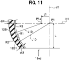
- FIG. 11 is a longitudinal cross-sectional view of the ball seat 12B in the lower left region defined by the reference line H1 and the vertical axis V1 in FIG. 10B that intersect with each other.
- the ball seat 12B in a taper shape in FIG. 11 has the same thickness as the ball seat 12A described above, but the inner face of the ball seat 12B includes a bottom face of the grease groove 12B1 as the circular arc R1 described above and a circular arc R3 that is the circular arc R1 widened by the groove depth t1.
- a thickness dt3 (lower end thickness) at the end of the lower opening 12od of the ball seat 12B in FIG. 11 is preferably set to be 0.4 mm or more. This is a value in consideration of fluidity of the molten resin at the time of injection molding the ball seat 12B, and the grease grooves 12B1 are also simultaneously molded by the injection molding. Further, the grease grooves 12B1 may also be formed in the ball seat 12 having a constant thickness described above.
- a thickness dt4 (reference thickness) between the circular arcs R2 and R3 at a position where the ball seat 12B intersects with the reference line H1 thereof is thickest in the taper shape.
- the force P (see FIG. 6 ) from above at the time of clamping is converted to the component force R in the peripheral direction of the ball seat 12B, to generated by wedge effect the ball holding force R for holding the ball portion 10b.
- the taper angle is in the range satisfying [2° ⁇ ⁇ 2 (see FIG. 6 ) ⁇ 9°].
- the ball portion 10b With the use of the ball seat 12B, the ball portion 10b can be held, by wedge effect, by the component force R in the peripheral direction of the ball seat 12B of the force P from above at the time of clamping. In this case, since lubricating oil flows in the grease grooves 12B1, the ball portion 10b can be swung and rotated smoothly. Further, since the ball seat 12B is simultaneously molded by injection molding, including the grease grooves 12B1, the ball seat 12B can be efficiently produced.
- FIG. 12 is a longitudinal cross-sectional view of the ball joint 1b with a housing 11A according to a third modification of the present embodiment.
- the housing 11A includes a ball seat fitting recess 11b (also referred to as a recess) surrounding, in a concave groove shape, the side portion of the spherical inner face 11a.
- the recess 11b includes a support portion 11c at its lower end, to fit the ball seat 12A described above in the concave groove that is formed in a concave groove shape.
- the ball seat 12A When the ball seat 12A is fitted, firstly, the ball portion 10b of the ball stud 10 is inserted in the spherical space of the ball seat 12A for assembly. Then, the assembled ball portion 10b and the ball seat 12A is inserted and set in the recess 11b of the housing 11A. This setting causes the lower end of the ball seat 12A to be arranged at the support portion 11c, and the upper face protrudes to be exposed above the spherical inner face 11a. Then, the clamped portion 11k is clamped.
- the ball seat 12A is pressed against the support portion 11c by the force from above at the time of clamping. With the pressing force, the ball seat 12A elastically deforms to bulge in the thickness direction. With the bulge, the clamping force (tightening margin) of the ball portion 10b in the ball seat 12A is controlled.
- the clamping is stopped at the optimal clamping position, while a pressing load Pa during the pressing from above as indicated by a vertical axis in FIG. 13 and a stroke length Sa indicated by a horizontal axis during the clamped portion 11k being clamped downward are measured.
- the optimal clamped position is at an inflection point of the clamped portion 11k where the pressing load is Pa1 and the stroke length is Sa1.
- the swing-and-slide torque is optimally reduced and the tightening margin is easily determined.
- the tightening margin at the optimal clamping position reduces the swing-and-slide torque and suppresses an increase of elastic lift to prevent clattering such that riding comfort of the vehicle is improved.
- the ball seat 12A the ball seat 12 or the ball seat 12B may be inserted in the recess 11b to obtain similar advantageous effects.
- FIG. 14 is a partially cross-sectional view of a configuration having a gap in a taper shape between the housing 11B and the ball portion 10b according to a fourth modification of the present embodiment.
- the fourth modification has a feature in which the cross-sectional shape of the gap between the spherical inner face 11a of the housing 11 and the outer periphery of the ball portion 10b is made in a taper shape below the reference line H1.
- a circular arc R4 of the outer periphery of the ball portion 10b has a straight line L11 with a given length from the center P1 as a radius.
- a circular arc R5 has the straight line L11 as a radius from a point P1b horizontally shifted by a given length j2 with respect to the center P1 in the radius direction of the ball portion 10b.
- the spherical inner face 11a is formed by the circular arc R5 below the reference line H1 of the housing 11B.
- the gap below the reference line H1 between the spherical inner face 11a of the housing 11 and the outer periphery of the ball portion 10b is tapered.
- a dimension dt5 at the lower end of the gap in a taper shape is smaller than a dimension dt6 at a position of intersection with the reference line H1.
- the ball holding force R for holding the ball portion 10b via the ball seat 12 is improved, and the tightening margin is more easily controlled. Therefore, swing-and-slide torque is reduced and elastic lift is suppressed from increasing to prevent clattering, resulting in improving riding comfort of the vehicle.
- the ball joint of the present invention is applicable to joints of a robot arm such as of an industrial robot and humanoid robot, and to a device having arms rotated at joints such as an excavator and a crane.
- stabilizer link 1a support bar (rod member) 1b: ball joint (connecting portion) 2: stabilizer (first structure body) 2b: arm portion 3: suspension device (second structure body) 3b: damper 10: ball stud 10b: ball portion (spherical body portion) 10s: stud portion 11, 11A, 11B: housing 11a: spherical inner face 11g: grease chamber 11k: clamped portion 12, 12A, 12B: ball seat (support member) 12k: spherical space 12op: upper opening (first opening) 12od: lower opening (second opening) 12B1: grease groove (groove) 13: dust cover
Applications Claiming Priority (2)
| Application Number | Priority Date | Filing Date | Title |
|---|---|---|---|
| JP2015196696A JP6300772B2 (ja) | 2015-10-02 | 2015-10-02 | ボールジョイント |
| PCT/JP2016/078474 WO2017057371A1 (fr) | 2015-10-02 | 2016-09-27 | Articulation à rotule |
Publications (3)
| Publication Number | Publication Date |
|---|---|
| EP3358205A1 true EP3358205A1 (fr) | 2018-08-08 |
| EP3358205A4 EP3358205A4 (fr) | 2019-06-05 |
| EP3358205B1 EP3358205B1 (fr) | 2020-07-15 |
Family
ID=58423607
Family Applications (1)
| Application Number | Title | Priority Date | Filing Date |
|---|---|---|---|
| EP16851542.7A Active EP3358205B1 (fr) | 2015-10-02 | 2016-09-27 | Articulation à rotule |
Country Status (6)
| Country | Link |
|---|---|
| US (1) | US11041524B2 (fr) |
| EP (1) | EP3358205B1 (fr) |
| JP (1) | JP6300772B2 (fr) |
| CN (1) | CN108026961B (fr) |
| ES (1) | ES2819851T3 (fr) |
| WO (1) | WO2017057371A1 (fr) |
Families Citing this family (6)
| Publication number | Priority date | Publication date | Assignee | Title |
|---|---|---|---|---|
| JP6335986B2 (ja) | 2016-08-25 | 2018-05-30 | 日本発條株式会社 | スタビリンク |
| JP2019018829A (ja) * | 2017-07-21 | 2019-02-07 | 日本発條株式会社 | スタビリンクのシール部構造、及びスタビリンク |
| EP3453593B1 (fr) * | 2017-09-01 | 2020-12-09 | Schaublin SA | Ensemble de pivot d'attelage avec une configuration de réception de couple |
| JP6836560B2 (ja) * | 2018-09-12 | 2021-03-03 | ファナック株式会社 | 関節カバー、ロボットおよびパラレルリンクロボット |
| EP3865720A4 (fr) * | 2018-10-11 | 2022-06-15 | NOK Corporation | Joint à rotule et capot anti-poussière |
| JP7260491B2 (ja) * | 2020-01-23 | 2023-04-18 | 日本発條株式会社 | ボールシート及びボールジョイント |
Family Cites Families (35)
| Publication number | Priority date | Publication date | Assignee | Title |
|---|---|---|---|---|
| US3154333A (en) * | 1962-08-16 | 1964-10-27 | Automotive Prod Co Ltd | Ball-and-socket joints |
| JPS4633042Y1 (fr) * | 1967-05-08 | 1971-11-15 | ||
| DE2057513A1 (de) * | 1970-11-23 | 1972-06-15 | Elastrogran Gmbh | Kugelgelenk |
| JPS529781B2 (fr) * | 1973-11-29 | 1977-03-18 | ||
| US4231673A (en) * | 1977-12-28 | 1980-11-04 | Oiles Industries Co., Ltd. | Ball joint and a method for manufacturing the ball joint |
| JPH0318739Y2 (fr) * | 1984-12-28 | 1991-04-19 | ||
| JPS6449719U (fr) * | 1987-09-22 | 1989-03-28 | ||
| US4904106A (en) * | 1989-06-26 | 1990-02-27 | Dana Corporation | Socket bearing |
| JPH0623567B2 (ja) * | 1990-01-16 | 1994-03-30 | 株式会社ソミック石川 | ボールジョイント |
| DE4211897C2 (de) * | 1992-04-09 | 1996-05-30 | Daimler Benz Ag | Kugelgelenk für Teile der Lenkung oder Radaufhängung von Kraftfahrzeugen |
| JP3168229B2 (ja) | 1992-10-06 | 2001-05-21 | 日本発条株式会社 | ボールジョイント装置 |
| JP3369659B2 (ja) | 1993-08-06 | 2003-01-20 | 日本発条株式会社 | ボールジョイント |
| JP3011119U (ja) * | 1994-11-14 | 1995-05-16 | 株式会社ソミック石川 | ボールジョイント |
| JPH08159147A (ja) * | 1994-12-08 | 1996-06-18 | Somic Ishikawa:Kk | ロッドエンド軸受装置 |
| JP4237314B2 (ja) * | 1998-12-18 | 2009-03-11 | 株式会社ソミック石川 | ボールジョイント |
| DE10028984C2 (de) * | 2000-06-16 | 2002-09-26 | Zf Lemfoerder Metallwaren Ag | Lagerschale für Kugelgelenke oder Kugelhülsengelenke |
| DE10110738C5 (de) * | 2001-03-01 | 2008-06-05 | ZF Lemförder GmbH | Kugelgelenk, Vorrichtung zum Steuern von Betriebsparametern eines Kraftfahrzeuges, Lenkgestänge, Spurstange sowie Verfahren zur Herstellung eines Kugelgelenks |
| JP2004116546A (ja) * | 2002-09-24 | 2004-04-15 | Musashi Seimitsu Ind Co Ltd | ボールジョイント |
| JP3880557B2 (ja) * | 2003-08-13 | 2007-02-14 | 日本発条株式会社 | ボールジョイント |
| DE102004040403A1 (de) * | 2004-08-19 | 2006-03-09 | Zf Friedrichshafen Ag | Kugelgelenk und Verfahren zu dessen Herstellung |
| CN101142415B (zh) * | 2005-03-15 | 2011-09-07 | Thk株式会社 | 球接头 |
| JP4573694B2 (ja) * | 2005-04-22 | 2010-11-04 | 株式会社ソミック石川 | ボールジョイント及びそのベアリングシート |
| JP4175548B2 (ja) * | 2005-07-15 | 2008-11-05 | 株式会社リズム | ボールジョイント及びボールシート |
| WO2008038458A1 (fr) | 2006-09-27 | 2008-04-03 | Thk Co., Ltd. | Roulement à rotule et procédé de fabrication de celui-ci |
| DE102006061974A1 (de) * | 2006-12-21 | 2008-07-10 | Zf Friedrichshafen Ag | Kugelgelenk mit Verschlussring |
| DE102008006846A1 (de) * | 2008-01-31 | 2009-08-06 | Daimler Ag | Kugelgelenk |
| JP5177518B2 (ja) * | 2008-06-10 | 2013-04-03 | 株式会社ジェイテクト | ボールジョイント |
| KR100948816B1 (ko) * | 2009-11-04 | 2010-03-19 | 주식회사 센트랄 링크텍 | 인서트 몰딩 형식의 볼조인트 |
| JP5357742B2 (ja) * | 2009-12-25 | 2013-12-04 | Thkリズム株式会社 | ボールジョイント |
| JP5165011B2 (ja) | 2010-02-16 | 2013-03-21 | 日本発條株式会社 | ボールジョイント装置 |
| JP5720934B2 (ja) * | 2011-01-25 | 2015-05-20 | 株式会社ジェイテクト | ボールジョイントおよびボールジョイントの製造方法 |
| JP5885547B2 (ja) * | 2012-03-09 | 2016-03-15 | Thk株式会社 | ボールジョイントの製造方法 |
| CN104024665B (zh) * | 2011-12-28 | 2017-08-08 | Thk株式会社 | 球窝接头及其制造方法 |
| JP6313555B2 (ja) * | 2013-08-06 | 2018-04-18 | 株式会社ソミック石川 | ボールジョイント及びその製造方法 |
| JP6449719B2 (ja) | 2015-05-27 | 2019-01-09 | ヤンマー株式会社 | 作業車 |
-
2015
- 2015-10-02 JP JP2015196696A patent/JP6300772B2/ja not_active Expired - Fee Related
-
2016
- 2016-09-27 EP EP16851542.7A patent/EP3358205B1/fr active Active
- 2016-09-27 ES ES16851542T patent/ES2819851T3/es active Active
- 2016-09-27 CN CN201680054932.1A patent/CN108026961B/zh active Active
- 2016-09-27 WO PCT/JP2016/078474 patent/WO2017057371A1/fr active Application Filing
- 2016-09-27 US US15/765,154 patent/US11041524B2/en active Active
Also Published As
| Publication number | Publication date |
|---|---|
| CN108026961A (zh) | 2018-05-11 |
| US20180298940A1 (en) | 2018-10-18 |
| ES2819851T3 (es) | 2021-04-19 |
| CN108026961B (zh) | 2021-05-04 |
| EP3358205A4 (fr) | 2019-06-05 |
| EP3358205B1 (fr) | 2020-07-15 |
| JP2017067260A (ja) | 2017-04-06 |
| JP6300772B2 (ja) | 2018-03-28 |
| WO2017057371A1 (fr) | 2017-04-06 |
| US11041524B2 (en) | 2021-06-22 |
Similar Documents
| Publication | Publication Date | Title |
|---|---|---|
| EP3358205B1 (fr) | Articulation à rotule | |
| US6254114B1 (en) | Composite stabilizer bar link | |
| WO2016132885A1 (fr) | Liaison de stabilisateur | |
| EP2722540A1 (fr) | Liaison de stabilisation et son procédé de production | |
| CA3015829C (fr) | Ensemble douille a angle d'oscillation restreint | |
| US20190118596A1 (en) | Axial Ball Joint And Length-Adjustable Two-Point Link With Such An Axial Ball Joint | |
| JP5728103B1 (ja) | リンクアーム部材 | |
| KR20180110119A (ko) | 볼 조인트 및 이것을 사용한 스태빌라이저 링크 | |
| US20140306412A1 (en) | Articulated connection for transferring a steering movement onto a vehicle wheel | |
| JP2011162093A (ja) | ショックアブソーバの取付構造 | |
| US11585372B2 (en) | Ball joint, stabilizer link using ball joint, and stabilizer assembly | |
| CN110497763B (zh) | 稳定杆连杆 | |
| CN108368872B (zh) | 球窝接头、铆接方法以及铆接模型 | |
| JP2011052730A (ja) | ボールジョイント | |
| US11754114B2 (en) | Ball joint, stabilizer link, and ball joint manufacturing method | |
| US11345203B2 (en) | Ball joint and hybrid suspension arm including same | |
| JP3548270B2 (ja) | 後輪用緩衝器のバネ荷重調整装置 | |
| CN114714840A (zh) | 一种减振器总成及汽车 | |
| JP5876267B2 (ja) | スタビライザブッシュおよび軸受装置 | |
| JP2003074633A (ja) | 筒型防振ブッシュ |
Legal Events
| Date | Code | Title | Description |
|---|---|---|---|
| STAA | Information on the status of an ep patent application or granted ep patent |
Free format text: STATUS: THE INTERNATIONAL PUBLICATION HAS BEEN MADE |
|
| PUAI | Public reference made under article 153(3) epc to a published international application that has entered the european phase |
Free format text: ORIGINAL CODE: 0009012 |
|
| STAA | Information on the status of an ep patent application or granted ep patent |
Free format text: STATUS: REQUEST FOR EXAMINATION WAS MADE |
|
| 17P | Request for examination filed |
Effective date: 20180426 |
|
| AK | Designated contracting states |
Kind code of ref document: A1 Designated state(s): AL AT BE BG CH CY CZ DE DK EE ES FI FR GB GR HR HU IE IS IT LI LT LU LV MC MK MT NL NO PL PT RO RS SE SI SK SM TR |
|
| AX | Request for extension of the european patent |
Extension state: BA ME |
|
| DAV | Request for validation of the european patent (deleted) | ||
| DAX | Request for extension of the european patent (deleted) | ||
| A4 | Supplementary search report drawn up and despatched |
Effective date: 20190506 |
|
| RIC1 | Information provided on ipc code assigned before grant |
Ipc: B60G 7/00 20060101ALI20190429BHEP Ipc: F16C 11/08 20060101AFI20190429BHEP Ipc: F16C 11/06 20060101ALI20190429BHEP Ipc: B60G 21/055 20060101ALI20190429BHEP |
|
| GRAP | Despatch of communication of intention to grant a patent |
Free format text: ORIGINAL CODE: EPIDOSNIGR1 |
|
| STAA | Information on the status of an ep patent application or granted ep patent |
Free format text: STATUS: GRANT OF PATENT IS INTENDED |
|
| INTG | Intention to grant announced |
Effective date: 20200211 |
|
| GRAS | Grant fee paid |
Free format text: ORIGINAL CODE: EPIDOSNIGR3 |
|
| GRAA | (expected) grant |
Free format text: ORIGINAL CODE: 0009210 |
|
| STAA | Information on the status of an ep patent application or granted ep patent |
Free format text: STATUS: THE PATENT HAS BEEN GRANTED |
|
| AK | Designated contracting states |
Kind code of ref document: B1 Designated state(s): AL AT BE BG CH CY CZ DE DK EE ES FI FR GB GR HR HU IE IS IT LI LT LU LV MC MK MT NL NO PL PT RO RS SE SI SK SM TR |
|
| REG | Reference to a national code |
Ref country code: CH Ref legal event code: EP Ref country code: GB Ref legal event code: FG4D |
|
| REG | Reference to a national code |
Ref country code: IE Ref legal event code: FG4D |
|
| REG | Reference to a national code |
Ref country code: DE Ref legal event code: R096 Ref document number: 602016040148 Country of ref document: DE |
|
| REG | Reference to a national code |
Ref country code: AT Ref legal event code: REF Ref document number: 1291342 Country of ref document: AT Kind code of ref document: T Effective date: 20200815 |
|
| REG | Reference to a national code |
Ref country code: LT Ref legal event code: MG4D |
|
| REG | Reference to a national code |
Ref country code: AT Ref legal event code: MK05 Ref document number: 1291342 Country of ref document: AT Kind code of ref document: T Effective date: 20200715 |
|
| REG | Reference to a national code |
Ref country code: NL Ref legal event code: MP Effective date: 20200715 |
|
| PG25 | Lapsed in a contracting state [announced via postgrant information from national office to epo] |
Ref country code: GR Free format text: LAPSE BECAUSE OF FAILURE TO SUBMIT A TRANSLATION OF THE DESCRIPTION OR TO PAY THE FEE WITHIN THE PRESCRIBED TIME-LIMIT Effective date: 20201016 Ref country code: BG Free format text: LAPSE BECAUSE OF FAILURE TO SUBMIT A TRANSLATION OF THE DESCRIPTION OR TO PAY THE FEE WITHIN THE PRESCRIBED TIME-LIMIT Effective date: 20201015 Ref country code: NO Free format text: LAPSE BECAUSE OF FAILURE TO SUBMIT A TRANSLATION OF THE DESCRIPTION OR TO PAY THE FEE WITHIN THE PRESCRIBED TIME-LIMIT Effective date: 20201015 Ref country code: AT Free format text: LAPSE BECAUSE OF FAILURE TO SUBMIT A TRANSLATION OF THE DESCRIPTION OR TO PAY THE FEE WITHIN THE PRESCRIBED TIME-LIMIT Effective date: 20200715 Ref country code: LT Free format text: LAPSE BECAUSE OF FAILURE TO SUBMIT A TRANSLATION OF THE DESCRIPTION OR TO PAY THE FEE WITHIN THE PRESCRIBED TIME-LIMIT Effective date: 20200715 Ref country code: PT Free format text: LAPSE BECAUSE OF FAILURE TO SUBMIT A TRANSLATION OF THE DESCRIPTION OR TO PAY THE FEE WITHIN THE PRESCRIBED TIME-LIMIT Effective date: 20201116 Ref country code: FI Free format text: LAPSE BECAUSE OF FAILURE TO SUBMIT A TRANSLATION OF THE DESCRIPTION OR TO PAY THE FEE WITHIN THE PRESCRIBED TIME-LIMIT Effective date: 20200715 Ref country code: SE Free format text: LAPSE BECAUSE OF FAILURE TO SUBMIT A TRANSLATION OF THE DESCRIPTION OR TO PAY THE FEE WITHIN THE PRESCRIBED TIME-LIMIT Effective date: 20200715 Ref country code: HR Free format text: LAPSE BECAUSE OF FAILURE TO SUBMIT A TRANSLATION OF THE DESCRIPTION OR TO PAY THE FEE WITHIN THE PRESCRIBED TIME-LIMIT Effective date: 20200715 |
|
| PG25 | Lapsed in a contracting state [announced via postgrant information from national office to epo] |
Ref country code: LV Free format text: LAPSE BECAUSE OF FAILURE TO SUBMIT A TRANSLATION OF THE DESCRIPTION OR TO PAY THE FEE WITHIN THE PRESCRIBED TIME-LIMIT Effective date: 20200715 Ref country code: PL Free format text: LAPSE BECAUSE OF FAILURE TO SUBMIT A TRANSLATION OF THE DESCRIPTION OR TO PAY THE FEE WITHIN THE PRESCRIBED TIME-LIMIT Effective date: 20200715 Ref country code: RS Free format text: LAPSE BECAUSE OF FAILURE TO SUBMIT A TRANSLATION OF THE DESCRIPTION OR TO PAY THE FEE WITHIN THE PRESCRIBED TIME-LIMIT Effective date: 20200715 Ref country code: IS Free format text: LAPSE BECAUSE OF FAILURE TO SUBMIT A TRANSLATION OF THE DESCRIPTION OR TO PAY THE FEE WITHIN THE PRESCRIBED TIME-LIMIT Effective date: 20201115 |
|
| PG25 | Lapsed in a contracting state [announced via postgrant information from national office to epo] |
Ref country code: NL Free format text: LAPSE BECAUSE OF FAILURE TO SUBMIT A TRANSLATION OF THE DESCRIPTION OR TO PAY THE FEE WITHIN THE PRESCRIBED TIME-LIMIT Effective date: 20200715 |
|
| REG | Reference to a national code |
Ref country code: DE Ref legal event code: R097 Ref document number: 602016040148 Country of ref document: DE |
|
| REG | Reference to a national code |
Ref country code: ES Ref legal event code: FG2A Ref document number: 2819851 Country of ref document: ES Kind code of ref document: T3 Effective date: 20210419 |
|
| PG25 | Lapsed in a contracting state [announced via postgrant information from national office to epo] |
Ref country code: EE Free format text: LAPSE BECAUSE OF FAILURE TO SUBMIT A TRANSLATION OF THE DESCRIPTION OR TO PAY THE FEE WITHIN THE PRESCRIBED TIME-LIMIT Effective date: 20200715 Ref country code: IT Free format text: LAPSE BECAUSE OF FAILURE TO SUBMIT A TRANSLATION OF THE DESCRIPTION OR TO PAY THE FEE WITHIN THE PRESCRIBED TIME-LIMIT Effective date: 20200715 Ref country code: SM Free format text: LAPSE BECAUSE OF FAILURE TO SUBMIT A TRANSLATION OF THE DESCRIPTION OR TO PAY THE FEE WITHIN THE PRESCRIBED TIME-LIMIT Effective date: 20200715 Ref country code: RO Free format text: LAPSE BECAUSE OF FAILURE TO SUBMIT A TRANSLATION OF THE DESCRIPTION OR TO PAY THE FEE WITHIN THE PRESCRIBED TIME-LIMIT Effective date: 20200715 Ref country code: CZ Free format text: LAPSE BECAUSE OF FAILURE TO SUBMIT A TRANSLATION OF THE DESCRIPTION OR TO PAY THE FEE WITHIN THE PRESCRIBED TIME-LIMIT Effective date: 20200715 Ref country code: DK Free format text: LAPSE BECAUSE OF FAILURE TO SUBMIT A TRANSLATION OF THE DESCRIPTION OR TO PAY THE FEE WITHIN THE PRESCRIBED TIME-LIMIT Effective date: 20200715 |
|
| REG | Reference to a national code |
Ref country code: CH Ref legal event code: PL |
|
| PLBE | No opposition filed within time limit |
Free format text: ORIGINAL CODE: 0009261 |
|
| STAA | Information on the status of an ep patent application or granted ep patent |
Free format text: STATUS: NO OPPOSITION FILED WITHIN TIME LIMIT |
|
| PG25 | Lapsed in a contracting state [announced via postgrant information from national office to epo] |
Ref country code: AL Free format text: LAPSE BECAUSE OF FAILURE TO SUBMIT A TRANSLATION OF THE DESCRIPTION OR TO PAY THE FEE WITHIN THE PRESCRIBED TIME-LIMIT Effective date: 20200715 |
|
| REG | Reference to a national code |
Ref country code: BE Ref legal event code: MM Effective date: 20200930 |
|
| 26N | No opposition filed |
Effective date: 20210416 |
|
| GBPC | Gb: european patent ceased through non-payment of renewal fee |
Effective date: 20201015 |
|
| PG25 | Lapsed in a contracting state [announced via postgrant information from national office to epo] |
Ref country code: LU Free format text: LAPSE BECAUSE OF NON-PAYMENT OF DUE FEES Effective date: 20200927 Ref country code: SK Free format text: LAPSE BECAUSE OF FAILURE TO SUBMIT A TRANSLATION OF THE DESCRIPTION OR TO PAY THE FEE WITHIN THE PRESCRIBED TIME-LIMIT Effective date: 20200715 |
|
| PG25 | Lapsed in a contracting state [announced via postgrant information from national office to epo] |
Ref country code: FR Free format text: LAPSE BECAUSE OF NON-PAYMENT OF DUE FEES Effective date: 20200930 |
|
| PG25 | Lapsed in a contracting state [announced via postgrant information from national office to epo] |
Ref country code: CH Free format text: LAPSE BECAUSE OF NON-PAYMENT OF DUE FEES Effective date: 20200930 Ref country code: BE Free format text: LAPSE BECAUSE OF NON-PAYMENT OF DUE FEES Effective date: 20200930 Ref country code: SI Free format text: LAPSE BECAUSE OF FAILURE TO SUBMIT A TRANSLATION OF THE DESCRIPTION OR TO PAY THE FEE WITHIN THE PRESCRIBED TIME-LIMIT Effective date: 20200715 Ref country code: LI Free format text: LAPSE BECAUSE OF NON-PAYMENT OF DUE FEES Effective date: 20200930 Ref country code: GB Free format text: LAPSE BECAUSE OF NON-PAYMENT OF DUE FEES Effective date: 20201015 Ref country code: IE Free format text: LAPSE BECAUSE OF NON-PAYMENT OF DUE FEES Effective date: 20200927 |
|
| REG | Reference to a national code |
Ref country code: DE Ref legal event code: R082 Ref document number: 602016040148 Country of ref document: DE Representative=s name: SIMMONS & SIMMONS LLP, DE |
|
| PG25 | Lapsed in a contracting state [announced via postgrant information from national office to epo] |
Ref country code: TR Free format text: LAPSE BECAUSE OF FAILURE TO SUBMIT A TRANSLATION OF THE DESCRIPTION OR TO PAY THE FEE WITHIN THE PRESCRIBED TIME-LIMIT Effective date: 20200715 Ref country code: MT Free format text: LAPSE BECAUSE OF FAILURE TO SUBMIT A TRANSLATION OF THE DESCRIPTION OR TO PAY THE FEE WITHIN THE PRESCRIBED TIME-LIMIT Effective date: 20200715 Ref country code: CY Free format text: LAPSE BECAUSE OF FAILURE TO SUBMIT A TRANSLATION OF THE DESCRIPTION OR TO PAY THE FEE WITHIN THE PRESCRIBED TIME-LIMIT Effective date: 20200715 |
|
| PG25 | Lapsed in a contracting state [announced via postgrant information from national office to epo] |
Ref country code: MK Free format text: LAPSE BECAUSE OF FAILURE TO SUBMIT A TRANSLATION OF THE DESCRIPTION OR TO PAY THE FEE WITHIN THE PRESCRIBED TIME-LIMIT Effective date: 20200715 Ref country code: MC Free format text: LAPSE BECAUSE OF FAILURE TO SUBMIT A TRANSLATION OF THE DESCRIPTION OR TO PAY THE FEE WITHIN THE PRESCRIBED TIME-LIMIT Effective date: 20200715 |
|
| PGFP | Annual fee paid to national office [announced via postgrant information from national office to epo] |
Ref country code: DE Payment date: 20230802 Year of fee payment: 8 |
|
| PGFP | Annual fee paid to national office [announced via postgrant information from national office to epo] |
Ref country code: ES Payment date: 20231003 Year of fee payment: 8 |