EP3354241B1 - Disruptive dressing for use with negative pressure and fluid instillation - Google Patents
Disruptive dressing for use with negative pressure and fluid instillation Download PDFInfo
- Publication number
- EP3354241B1 EP3354241B1 EP18162504.7A EP18162504A EP3354241B1 EP 3354241 B1 EP3354241 B1 EP 3354241B1 EP 18162504 A EP18162504 A EP 18162504A EP 3354241 B1 EP3354241 B1 EP 3354241B1
- Authority
- EP
- European Patent Office
- Prior art keywords
- contact layer
- tissue
- holes
- tissue site
- debris
- Prior art date
- Legal status (The legal status is an assumption and is not a legal conclusion. Google has not performed a legal analysis and makes no representation as to the accuracy of the status listed.)
- Active
Links
- 239000012530 fluid Substances 0.000 title claims description 66
- 239000000463 material Substances 0.000 claims description 31
- 239000011800 void material Substances 0.000 claims description 17
- 230000004044 response Effects 0.000 claims description 8
- 229920002725 thermoplastic elastomer Polymers 0.000 claims description 8
- 239000004744 fabric Substances 0.000 claims description 3
- 125000006850 spacer group Chemical group 0.000 claims description 2
- 210000001519 tissue Anatomy 0.000 description 250
- 238000002560 therapeutic procedure Methods 0.000 description 120
- 239000006260 foam Substances 0.000 description 85
- 230000001225 therapeutic effect Effects 0.000 description 65
- 238000000034 method Methods 0.000 description 39
- 230000008569 process Effects 0.000 description 26
- 238000011282 treatment Methods 0.000 description 26
- 238000001804 debridement Methods 0.000 description 23
- 208000027418 Wounds and injury Diseases 0.000 description 18
- 239000011148 porous material Substances 0.000 description 18
- 206010052428 Wound Diseases 0.000 description 17
- 206010033675 panniculitis Diseases 0.000 description 13
- 210000004304 subcutaneous tissue Anatomy 0.000 description 13
- 239000006261 foam material Substances 0.000 description 12
- 230000001338 necrotic effect Effects 0.000 description 12
- 230000008602 contraction Effects 0.000 description 11
- 230000007423 decrease Effects 0.000 description 11
- 210000000416 exudates and transudate Anatomy 0.000 description 11
- 230000035876 healing Effects 0.000 description 11
- 239000011159 matrix material Substances 0.000 description 11
- 239000000243 solution Substances 0.000 description 11
- 230000002358 autolytic effect Effects 0.000 description 10
- 206010051814 Eschar Diseases 0.000 description 9
- 230000006835 compression Effects 0.000 description 9
- 238000007906 compression Methods 0.000 description 9
- 238000005520 cutting process Methods 0.000 description 9
- 231100000333 eschar Toxicity 0.000 description 9
- 208000015181 infectious disease Diseases 0.000 description 9
- 230000015572 biosynthetic process Effects 0.000 description 8
- 108090000790 Enzymes Proteins 0.000 description 7
- 102000004190 Enzymes Human genes 0.000 description 7
- 239000004433 Thermoplastic polyurethane Substances 0.000 description 7
- 229920002803 thermoplastic polyurethane Polymers 0.000 description 7
- 230000008901 benefit Effects 0.000 description 6
- 208000014674 injury Diseases 0.000 description 6
- 206010063560 Excessive granulation tissue Diseases 0.000 description 5
- 229920005830 Polyurethane Foam Polymers 0.000 description 5
- 230000006378 damage Effects 0.000 description 5
- 210000001126 granulation tissue Anatomy 0.000 description 5
- 239000007788 liquid Substances 0.000 description 5
- 238000010297 mechanical methods and process Methods 0.000 description 5
- 230000005226 mechanical processes and functions Effects 0.000 description 5
- 239000011496 polyurethane foam Substances 0.000 description 5
- 238000007789 sealing Methods 0.000 description 5
- 230000000699 topical effect Effects 0.000 description 5
- 230000008733 trauma Effects 0.000 description 5
- 210000004027 cell Anatomy 0.000 description 4
- 230000010261 cell growth Effects 0.000 description 4
- 230000008859 change Effects 0.000 description 4
- 230000003247 decreasing effect Effects 0.000 description 4
- 230000000087 stabilizing effect Effects 0.000 description 4
- 239000000126 substance Substances 0.000 description 4
- 238000012360 testing method Methods 0.000 description 4
- 229920000954 Polyglycolide Polymers 0.000 description 3
- 208000033809 Suppuration Diseases 0.000 description 3
- 208000025865 Ulcer Diseases 0.000 description 3
- 230000009286 beneficial effect Effects 0.000 description 3
- 239000001913 cellulose Substances 0.000 description 3
- 229920002678 cellulose Polymers 0.000 description 3
- 125000004122 cyclic group Chemical group 0.000 description 3
- 238000011161 development Methods 0.000 description 3
- 230000002255 enzymatic effect Effects 0.000 description 3
- 210000002615 epidermis Anatomy 0.000 description 3
- 230000002209 hydrophobic effect Effects 0.000 description 3
- 230000001788 irregular Effects 0.000 description 3
- 239000000203 mixture Substances 0.000 description 3
- 239000002245 particle Substances 0.000 description 3
- 230000037361 pathway Effects 0.000 description 3
- 239000004633 polyglycolic acid Substances 0.000 description 3
- 238000003860 storage Methods 0.000 description 3
- 231100000397 ulcer Toxicity 0.000 description 3
- 238000013022 venting Methods 0.000 description 3
- 102000008186 Collagen Human genes 0.000 description 2
- 108010035532 Collagen Proteins 0.000 description 2
- 206010070245 Foreign body Diseases 0.000 description 2
- 206010017533 Fungal infection Diseases 0.000 description 2
- 206010020649 Hyperkeratosis Diseases 0.000 description 2
- 206010061218 Inflammation Diseases 0.000 description 2
- 241001465754 Metazoa Species 0.000 description 2
- 208000031888 Mycoses Diseases 0.000 description 2
- 206010030113 Oedema Diseases 0.000 description 2
- 239000004372 Polyvinyl alcohol Substances 0.000 description 2
- 229920001247 Reticulated foam Polymers 0.000 description 2
- 206010000269 abscess Diseases 0.000 description 2
- 230000009471 action Effects 0.000 description 2
- 239000000853 adhesive Substances 0.000 description 2
- 230000001070 adhesive effect Effects 0.000 description 2
- 230000001580 bacterial effect Effects 0.000 description 2
- 230000004888 barrier function Effects 0.000 description 2
- 230000000740 bleeding effect Effects 0.000 description 2
- 239000008280 blood Substances 0.000 description 2
- 210000004369 blood Anatomy 0.000 description 2
- 230000001413 cellular effect Effects 0.000 description 2
- 239000011248 coating agent Substances 0.000 description 2
- 238000000576 coating method Methods 0.000 description 2
- 229920001436 collagen Polymers 0.000 description 2
- 230000001419 dependent effect Effects 0.000 description 2
- 210000004207 dermis Anatomy 0.000 description 2
- 230000002500 effect on skin Effects 0.000 description 2
- 230000000694 effects Effects 0.000 description 2
- 239000000499 gel Substances 0.000 description 2
- 230000012010 growth Effects 0.000 description 2
- 230000000887 hydrating effect Effects 0.000 description 2
- WQYVRQLZKVEZGA-UHFFFAOYSA-N hypochlorite Chemical compound Cl[O-] WQYVRQLZKVEZGA-UHFFFAOYSA-N 0.000 description 2
- 230000001771 impaired effect Effects 0.000 description 2
- 230000004054 inflammatory process Effects 0.000 description 2
- 238000003698 laser cutting Methods 0.000 description 2
- 230000033001 locomotion Effects 0.000 description 2
- 230000007246 mechanism Effects 0.000 description 2
- 229910052751 metal Inorganic materials 0.000 description 2
- 239000002184 metal Substances 0.000 description 2
- 150000002739 metals Chemical class 0.000 description 2
- 235000019645 odor Nutrition 0.000 description 2
- 239000001814 pectin Substances 0.000 description 2
- 229920001277 pectin Polymers 0.000 description 2
- 235000010987 pectin Nutrition 0.000 description 2
- 239000004626 polylactic acid Substances 0.000 description 2
- 229920001296 polysiloxane Polymers 0.000 description 2
- 229920002451 polyvinyl alcohol Polymers 0.000 description 2
- 230000010349 pulsation Effects 0.000 description 2
- 238000000926 separation method Methods 0.000 description 2
- SQGYOTSLMSWVJD-UHFFFAOYSA-N silver(1+) nitrate Chemical compound [Ag+].[O-]N(=O)=O SQGYOTSLMSWVJD-UHFFFAOYSA-N 0.000 description 2
- 239000004753 textile Substances 0.000 description 2
- XLYOFNOQVPJJNP-UHFFFAOYSA-N water Chemical compound O XLYOFNOQVPJJNP-UHFFFAOYSA-N 0.000 description 2
- 238000003466 welding Methods 0.000 description 2
- 241000193738 Bacillus anthracis Species 0.000 description 1
- 208000035143 Bacterial infection Diseases 0.000 description 1
- 229940123208 Biguanide Drugs 0.000 description 1
- 235000014653 Carica parviflora Nutrition 0.000 description 1
- 241000243321 Cnidaria Species 0.000 description 1
- RYGMFSIKBFXOCR-UHFFFAOYSA-N Copper Chemical compound [Cu] RYGMFSIKBFXOCR-UHFFFAOYSA-N 0.000 description 1
- 102000009123 Fibrin Human genes 0.000 description 1
- 108010073385 Fibrin Proteins 0.000 description 1
- BWGVNKXGVNDBDI-UHFFFAOYSA-N Fibrin monomer Chemical compound CNC(=O)CNC(=O)CN BWGVNKXGVNDBDI-UHFFFAOYSA-N 0.000 description 1
- 206010017711 Gangrene Diseases 0.000 description 1
- 206010028851 Necrosis Diseases 0.000 description 1
- 239000004721 Polyphenylene oxide Substances 0.000 description 1
- 239000004820 Pressure-sensitive adhesive Substances 0.000 description 1
- BQCADISMDOOEFD-UHFFFAOYSA-N Silver Chemical compound [Ag] BQCADISMDOOEFD-UHFFFAOYSA-N 0.000 description 1
- FAPWRFPIFSIZLT-UHFFFAOYSA-M Sodium chloride Chemical compound [Na+].[Cl-] FAPWRFPIFSIZLT-UHFFFAOYSA-M 0.000 description 1
- 208000003589 Spider Bites Diseases 0.000 description 1
- NINIDFKCEFEMDL-UHFFFAOYSA-N Sulfur Chemical compound [S] NINIDFKCEFEMDL-UHFFFAOYSA-N 0.000 description 1
- 241000282898 Sus scrofa Species 0.000 description 1
- ATJFFYVFTNAWJD-UHFFFAOYSA-N Tin Chemical compound [Sn] ATJFFYVFTNAWJD-UHFFFAOYSA-N 0.000 description 1
- 238000005299 abrasion Methods 0.000 description 1
- 239000003522 acrylic cement Substances 0.000 description 1
- 230000001154 acute effect Effects 0.000 description 1
- 210000000577 adipose tissue Anatomy 0.000 description 1
- 230000000844 anti-bacterial effect Effects 0.000 description 1
- 208000022362 bacterial infectious disease Diseases 0.000 description 1
- SNHRLVCMMWUAJD-SUYDQAKGSA-N betamethasone valerate Chemical compound C1CC2=CC(=O)C=C[C@]2(C)[C@]2(F)[C@@H]1[C@@H]1C[C@H](C)[C@@](C(=O)CO)(OC(=O)CCCC)[C@@]1(C)C[C@@H]2O SNHRLVCMMWUAJD-SUYDQAKGSA-N 0.000 description 1
- 150000004283 biguanides Chemical class 0.000 description 1
- 230000000903 blocking effect Effects 0.000 description 1
- 230000017531 blood circulation Effects 0.000 description 1
- 210000000988 bone and bone Anatomy 0.000 description 1
- 239000001506 calcium phosphate Substances 0.000 description 1
- 229910000389 calcium phosphate Inorganic materials 0.000 description 1
- 235000011010 calcium phosphates Nutrition 0.000 description 1
- 150000004649 carbonic acid derivatives Chemical class 0.000 description 1
- 210000000845 cartilage Anatomy 0.000 description 1
- 125000002091 cationic group Chemical group 0.000 description 1
- 238000012412 chemical coupling Methods 0.000 description 1
- 238000006243 chemical reaction Methods 0.000 description 1
- 239000003795 chemical substances by application Substances 0.000 description 1
- 230000001684 chronic effect Effects 0.000 description 1
- 210000002808 connective tissue Anatomy 0.000 description 1
- 229920001577 copolymer Polymers 0.000 description 1
- 229910052802 copper Inorganic materials 0.000 description 1
- 239000010949 copper Substances 0.000 description 1
- 230000008878 coupling Effects 0.000 description 1
- 238000010168 coupling process Methods 0.000 description 1
- 238000005859 coupling reaction Methods 0.000 description 1
- 230000007547 defect Effects 0.000 description 1
- 230000002950 deficient Effects 0.000 description 1
- 230000001934 delay Effects 0.000 description 1
- 230000006866 deterioration Effects 0.000 description 1
- 206010012601 diabetes mellitus Diseases 0.000 description 1
- 229910003460 diamond Inorganic materials 0.000 description 1
- 239000010432 diamond Substances 0.000 description 1
- 238000009826 distribution Methods 0.000 description 1
- 238000005553 drilling Methods 0.000 description 1
- 210000000981 epithelium Anatomy 0.000 description 1
- 238000009950 felting Methods 0.000 description 1
- 229950003499 fibrin Drugs 0.000 description 1
- 238000007667 floating Methods 0.000 description 1
- 238000011010 flushing procedure Methods 0.000 description 1
- 230000006870 function Effects 0.000 description 1
- 238000005469 granulation Methods 0.000 description 1
- 230000003179 granulation Effects 0.000 description 1
- 230000037313 granulation tissue formation Effects 0.000 description 1
- 230000005484 gravity Effects 0.000 description 1
- 150000004677 hydrates Chemical class 0.000 description 1
- 239000000416 hydrocolloid Substances 0.000 description 1
- 239000000017 hydrogel Substances 0.000 description 1
- 230000002706 hydrostatic effect Effects 0.000 description 1
- 125000002887 hydroxy group Chemical group [H]O* 0.000 description 1
- 230000002458 infectious effect Effects 0.000 description 1
- 230000028709 inflammatory response Effects 0.000 description 1
- 238000003780 insertion Methods 0.000 description 1
- 230000037431 insertion Effects 0.000 description 1
- 239000000644 isotonic solution Substances 0.000 description 1
- 230000029774 keratinocyte migration Effects 0.000 description 1
- 230000002045 lasting effect Effects 0.000 description 1
- 210000003041 ligament Anatomy 0.000 description 1
- 239000003589 local anesthetic agent Substances 0.000 description 1
- 229960005015 local anesthetics Drugs 0.000 description 1
- 230000014759 maintenance of location Effects 0.000 description 1
- 230000008018 melting Effects 0.000 description 1
- 238000002844 melting Methods 0.000 description 1
- 239000012528 membrane Substances 0.000 description 1
- 230000000813 microbial effect Effects 0.000 description 1
- 230000005012 migration Effects 0.000 description 1
- 238000013508 migration Methods 0.000 description 1
- 238000012986 modification Methods 0.000 description 1
- 230000004048 modification Effects 0.000 description 1
- 238000012544 monitoring process Methods 0.000 description 1
- 238000000465 moulding Methods 0.000 description 1
- 210000003205 muscle Anatomy 0.000 description 1
- 230000017074 necrotic cell death Effects 0.000 description 1
- 238000009581 negative-pressure wound therapy Methods 0.000 description 1
- 230000001537 neural effect Effects 0.000 description 1
- 230000008520 organization Effects 0.000 description 1
- 230000036407 pain Effects 0.000 description 1
- 230000037325 pain tolerance Effects 0.000 description 1
- 239000006072 paste Substances 0.000 description 1
- 230000002093 peripheral effect Effects 0.000 description 1
- 230000002572 peristaltic effect Effects 0.000 description 1
- 229940021222 peritoneal dialysis isotonic solution Drugs 0.000 description 1
- 230000035699 permeability Effects 0.000 description 1
- 229920000747 poly(lactic acid) Polymers 0.000 description 1
- 239000004417 polycarbonate Substances 0.000 description 1
- 229920000515 polycarbonate Polymers 0.000 description 1
- 229920000728 polyester Polymers 0.000 description 1
- 229920000570 polyether Polymers 0.000 description 1
- 229920000642 polymer Polymers 0.000 description 1
- 229920000098 polyolefin Polymers 0.000 description 1
- 229920002635 polyurethane Polymers 0.000 description 1
- 239000004814 polyurethane Substances 0.000 description 1
- 229920006264 polyurethane film Polymers 0.000 description 1
- 238000002360 preparation method Methods 0.000 description 1
- 238000012545 processing Methods 0.000 description 1
- 230000000717 retained effect Effects 0.000 description 1
- 229920006395 saturated elastomer Polymers 0.000 description 1
- 229910052709 silver Inorganic materials 0.000 description 1
- 239000004332 silver Substances 0.000 description 1
- 229910001961 silver nitrate Inorganic materials 0.000 description 1
- 239000011780 sodium chloride Substances 0.000 description 1
- 239000007787 solid Substances 0.000 description 1
- 239000007921 spray Substances 0.000 description 1
- 230000004936 stimulating effect Effects 0.000 description 1
- -1 styrene ethylene butylene styrene Chemical class 0.000 description 1
- 238000007920 subcutaneous administration Methods 0.000 description 1
- 239000011593 sulfur Substances 0.000 description 1
- 229910052717 sulfur Inorganic materials 0.000 description 1
- 238000001356 surgical procedure Methods 0.000 description 1
- 239000003826 tablet Substances 0.000 description 1
- 210000002435 tendon Anatomy 0.000 description 1
- 238000003856 thermoforming Methods 0.000 description 1
- 229910052718 tin Inorganic materials 0.000 description 1
- 239000011135 tin Substances 0.000 description 1
- 230000000451 tissue damage Effects 0.000 description 1
- 231100000827 tissue damage Toxicity 0.000 description 1
- 239000003053 toxin Substances 0.000 description 1
- 231100000765 toxin Toxicity 0.000 description 1
- 108700012359 toxins Proteins 0.000 description 1
- 238000012546 transfer Methods 0.000 description 1
- 230000000472 traumatic effect Effects 0.000 description 1
- QORWJWZARLRLPR-UHFFFAOYSA-H tricalcium bis(phosphate) Chemical compound [Ca+2].[Ca+2].[Ca+2].[O-]P([O-])([O-])=O.[O-]P([O-])([O-])=O QORWJWZARLRLPR-UHFFFAOYSA-H 0.000 description 1
- 238000011144 upstream manufacturing Methods 0.000 description 1
- 230000008016 vaporization Effects 0.000 description 1
- 230000002792 vascular Effects 0.000 description 1
- 201000002282 venous insufficiency Diseases 0.000 description 1
- 230000000007 visual effect Effects 0.000 description 1
- 239000002699 waste material Substances 0.000 description 1
Images


Classifications
-
- A—HUMAN NECESSITIES
- A61—MEDICAL OR VETERINARY SCIENCE; HYGIENE
- A61B—DIAGNOSIS; SURGERY; IDENTIFICATION
- A61B17/00—Surgical instruments, devices or methods, e.g. tourniquets
- A61B17/32—Surgical cutting instruments
-
- A—HUMAN NECESSITIES
- A61—MEDICAL OR VETERINARY SCIENCE; HYGIENE
- A61B—DIAGNOSIS; SURGERY; IDENTIFICATION
- A61B17/00—Surgical instruments, devices or methods, e.g. tourniquets
- A61B17/22—Implements for squeezing-off ulcers or the like on the inside of inner organs of the body; Implements for scraping-out cavities of body organs, e.g. bones; Calculus removers; Calculus smashing apparatus; Apparatus for removing obstructions in blood vessels, not otherwise provided for
- A61B17/22004—Implements for squeezing-off ulcers or the like on the inside of inner organs of the body; Implements for scraping-out cavities of body organs, e.g. bones; Calculus removers; Calculus smashing apparatus; Apparatus for removing obstructions in blood vessels, not otherwise provided for using mechanical vibrations, e.g. ultrasonic shock waves
-
- A—HUMAN NECESSITIES
- A61—MEDICAL OR VETERINARY SCIENCE; HYGIENE
- A61F—FILTERS IMPLANTABLE INTO BLOOD VESSELS; PROSTHESES; DEVICES PROVIDING PATENCY TO, OR PREVENTING COLLAPSING OF, TUBULAR STRUCTURES OF THE BODY, e.g. STENTS; ORTHOPAEDIC, NURSING OR CONTRACEPTIVE DEVICES; FOMENTATION; TREATMENT OR PROTECTION OF EYES OR EARS; BANDAGES, DRESSINGS OR ABSORBENT PADS; FIRST-AID KITS
- A61F13/00—Bandages or dressings; Absorbent pads
- A61F13/05—Bandages or dressings; Absorbent pads specially adapted for use with sub-pressure or over-pressure therapy, wound drainage or wound irrigation, e.g. for use with negative-pressure wound therapy [NPWT]
-
- A—HUMAN NECESSITIES
- A61—MEDICAL OR VETERINARY SCIENCE; HYGIENE
- A61M—DEVICES FOR INTRODUCING MEDIA INTO, OR ONTO, THE BODY; DEVICES FOR TRANSDUCING BODY MEDIA OR FOR TAKING MEDIA FROM THE BODY; DEVICES FOR PRODUCING OR ENDING SLEEP OR STUPOR
- A61M1/00—Suction or pumping devices for medical purposes; Devices for carrying-off, for treatment of, or for carrying-over, body-liquids; Drainage systems
- A61M1/84—Drainage tubes; Aspiration tips
- A61M1/85—Drainage tubes; Aspiration tips with gas or fluid supply means, e.g. for supplying rinsing fluids or anticoagulants
-
- A—HUMAN NECESSITIES
- A61—MEDICAL OR VETERINARY SCIENCE; HYGIENE
- A61M—DEVICES FOR INTRODUCING MEDIA INTO, OR ONTO, THE BODY; DEVICES FOR TRANSDUCING BODY MEDIA OR FOR TAKING MEDIA FROM THE BODY; DEVICES FOR PRODUCING OR ENDING SLEEP OR STUPOR
- A61M1/00—Suction or pumping devices for medical purposes; Devices for carrying-off, for treatment of, or for carrying-over, body-liquids; Drainage systems
- A61M1/90—Negative pressure wound therapy devices, i.e. devices for applying suction to a wound to promote healing, e.g. including a vacuum dressing
- A61M1/91—Suction aspects of the dressing
- A61M1/915—Constructional details of the pressure distribution manifold
-
- A—HUMAN NECESSITIES
- A61—MEDICAL OR VETERINARY SCIENCE; HYGIENE
- A61M—DEVICES FOR INTRODUCING MEDIA INTO, OR ONTO, THE BODY; DEVICES FOR TRANSDUCING BODY MEDIA OR FOR TAKING MEDIA FROM THE BODY; DEVICES FOR PRODUCING OR ENDING SLEEP OR STUPOR
- A61M1/00—Suction or pumping devices for medical purposes; Devices for carrying-off, for treatment of, or for carrying-over, body-liquids; Drainage systems
- A61M1/90—Negative pressure wound therapy devices, i.e. devices for applying suction to a wound to promote healing, e.g. including a vacuum dressing
- A61M1/92—Negative pressure wound therapy devices, i.e. devices for applying suction to a wound to promote healing, e.g. including a vacuum dressing with liquid supply means
-
- A—HUMAN NECESSITIES
- A61—MEDICAL OR VETERINARY SCIENCE; HYGIENE
- A61M—DEVICES FOR INTRODUCING MEDIA INTO, OR ONTO, THE BODY; DEVICES FOR TRANSDUCING BODY MEDIA OR FOR TAKING MEDIA FROM THE BODY; DEVICES FOR PRODUCING OR ENDING SLEEP OR STUPOR
- A61M27/00—Drainage appliance for wounds or the like, i.e. wound drains, implanted drains
-
- A—HUMAN NECESSITIES
- A61—MEDICAL OR VETERINARY SCIENCE; HYGIENE
- A61B—DIAGNOSIS; SURGERY; IDENTIFICATION
- A61B17/00—Surgical instruments, devices or methods, e.g. tourniquets
- A61B17/22—Implements for squeezing-off ulcers or the like on the inside of inner organs of the body; Implements for scraping-out cavities of body organs, e.g. bones; Calculus removers; Calculus smashing apparatus; Apparatus for removing obstructions in blood vessels, not otherwise provided for
- A61B17/22004—Implements for squeezing-off ulcers or the like on the inside of inner organs of the body; Implements for scraping-out cavities of body organs, e.g. bones; Calculus removers; Calculus smashing apparatus; Apparatus for removing obstructions in blood vessels, not otherwise provided for using mechanical vibrations, e.g. ultrasonic shock waves
- A61B2017/22005—Effects, e.g. on tissue
- A61B2017/22007—Cavitation or pseudocavitation, i.e. creation of gas bubbles generating a secondary shock wave when collapsing
- A61B2017/22008—Cavitation or pseudocavitation, i.e. creation of gas bubbles generating a secondary shock wave when collapsing used or promoted
-
- A—HUMAN NECESSITIES
- A61—MEDICAL OR VETERINARY SCIENCE; HYGIENE
- A61B—DIAGNOSIS; SURGERY; IDENTIFICATION
- A61B17/00—Surgical instruments, devices or methods, e.g. tourniquets
- A61B17/22—Implements for squeezing-off ulcers or the like on the inside of inner organs of the body; Implements for scraping-out cavities of body organs, e.g. bones; Calculus removers; Calculus smashing apparatus; Apparatus for removing obstructions in blood vessels, not otherwise provided for
- A61B2017/22082—Implements for squeezing-off ulcers or the like on the inside of inner organs of the body; Implements for scraping-out cavities of body organs, e.g. bones; Calculus removers; Calculus smashing apparatus; Apparatus for removing obstructions in blood vessels, not otherwise provided for after introduction of a substance
- A61B2017/22089—Gas-bubbles
-
- A—HUMAN NECESSITIES
- A61—MEDICAL OR VETERINARY SCIENCE; HYGIENE
- A61B—DIAGNOSIS; SURGERY; IDENTIFICATION
- A61B17/00—Surgical instruments, devices or methods, e.g. tourniquets
- A61B17/32—Surgical cutting instruments
- A61B2017/320004—Surgical cutting instruments abrasive
- A61B2017/320008—Scrapers
-
- A—HUMAN NECESSITIES
- A61—MEDICAL OR VETERINARY SCIENCE; HYGIENE
- A61B—DIAGNOSIS; SURGERY; IDENTIFICATION
- A61B17/00—Surgical instruments, devices or methods, e.g. tourniquets
- A61B17/32—Surgical cutting instruments
- A61B2017/32006—Surgical cutting instruments with a cutting strip, band or chain, e.g. like a chainsaw
-
- A—HUMAN NECESSITIES
- A61—MEDICAL OR VETERINARY SCIENCE; HYGIENE
- A61B—DIAGNOSIS; SURGERY; IDENTIFICATION
- A61B17/00—Surgical instruments, devices or methods, e.g. tourniquets
- A61B17/32—Surgical cutting instruments
- A61B2017/320064—Surgical cutting instruments with tissue or sample retaining means
-
- A—HUMAN NECESSITIES
- A61—MEDICAL OR VETERINARY SCIENCE; HYGIENE
- A61M—DEVICES FOR INTRODUCING MEDIA INTO, OR ONTO, THE BODY; DEVICES FOR TRANSDUCING BODY MEDIA OR FOR TAKING MEDIA FROM THE BODY; DEVICES FOR PRODUCING OR ENDING SLEEP OR STUPOR
- A61M1/00—Suction or pumping devices for medical purposes; Devices for carrying-off, for treatment of, or for carrying-over, body-liquids; Drainage systems
- A61M1/90—Negative pressure wound therapy devices, i.e. devices for applying suction to a wound to promote healing, e.g. including a vacuum dressing
- A61M1/96—Suction control thereof
Definitions
- the invention set forth in the appended claims relates generally to tissue treatment systems and more particularly, but without limitation, to a dressing for disrupting non-viable tissue at a tissue site.
- Negative-pressure therapy may provide a number of benefits, including migration of epithelial and subcutaneous tissues, improved blood flow, and micro-deformation of tissue at a wound site. Together, these benefits can increase development of granulation tissue and reduce healing times.
- tissue debris located in or on a tissue site may hinder the application of beneficial therapy, increasing healing times and the risk of further tissue damage.
- Debris can include necrotic tissue, foreign bodies, biofilms, slough, eschar, and other debris that can negatively impact tissue healing. Removal of the tissue debris can be accomplished through debridement processes; however, debridement processes can be painful to a patient and may result in further damage to the tissue site. Debriding a tissue site can also be a time-consuming process that may significantly delay the application of other beneficial therapies, such as negative-pressure therapy or instillation therapy.
- beneficial therapies such as negative-pressure therapy or instillation therapy.
- WO2014/014922A1 discusses a stabilizing structure for insertion into a wound.
- the stabilizing structure comprises a plurality of cells provided side-by-side in a plane, each cell defined by one or more walls, each cell having a top end and a bottom end with an opening extending through the top and bottom ends in the direction perpendicular to the plane.
- the stabilizing structure is configured to collapse significantly more within the plane than along the direction perpendicular to the plane.
- the stabilizing structure may be constructed from a foam.
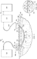
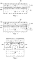
- FIG 1 is a sectional view, with a portion shown in elevation, of an example embodiment of a therapy system 100 that can provide negative pressure therapy, instillation of topical treatment solutions, and disruption of debris on tissue in accordance with this specification.
- the therapy system 100 may include a dressing and a negative-pressure source.
- a dressing 102 may be fluidly coupled to a negative-pressure source 104, as illustrated in Figure 1.
- Figure 1A is a detail view of a portion of the therapy system 100 of Figure 1 .
- the dressing 102 for example, includes a cover, such as a drape 106, and a tissue interface 107 for positioning adjacent to or proximate to a tissue site such as, for example, a tissue site 103.
- the tissue interface 107 may be a cover layer, such as a retainer layer 108
- the tissue interface 107 can also be a contact layer 110 having a tissue-facing surface 111 adapted to face the tissue site 103 and an opposite surface 113 adapted to face, for example, the retainer layer 108.
- the tissue interface 107 can be both the retainer layer 108 and the contact layer 110, and the retainer layer 108 and the contact layer 110 may be integral components.
- the tissue interface 107 can include the retainer layer 108 and the contact layer 110, and the retainer layer and the contact layer 110 may be separate components as shown in Figure 1 .
- the therapy system 100 may also include an exudate container, such as a container 112, coupled to the dressing 102 and to the negative-pressure source 104.
- a container 112 may be fluidly coupled to the dressing 102 by a connector 114 and a tube 116, and the container 112 may be fluidly coupled to the negative-pressure source 104 by a tube 118.
- the therapy system 100 may also include an instillation solution source.
- a fluid source 120 may be fluidly coupled to the dressing 102 by a tube 122 and a connector 124, as illustrated in the example embodiment of Figure 1 .
- components of the therapy system 100 may be coupled directly or indirectly.
- the negative-pressure source 104 may be directly coupled to the container 112 and indirectly coupled to the dressing 102 through the container 112.
- Components may be fluidly coupled to each other to provide a path for transferring fluids (i.e., liquid and/or gas) between the components.
- components may be fluidly coupled through a tube, such as the tube 116, the tube 118, and the tube 122.
- a tube is an elongated, cylindrical structure with some flexibility, but the geometry and rigidity may vary.
- Components may also be fluidly coupled without the use of a tube, for example, by having surfaces in contact with or proximate to each other.
- components may additionally or alternatively be coupled by virtue of physical proximity, being integral to a single structure, or being formed from the same piece of material.
- components may be coupled by being positioned adjacent to each other or by being operable with each other. Coupling may also include mechanical, thermal, electrical, or chemical coupling (such as a chemical bond) in some contexts.
- the tissue interface 107 may be placed within, over, on, or otherwise proximate to the tissue site 103.
- the drape 106 may be placed over the tissue interface 107 and sealed to tissue near the tissue site.
- the drape 106 may be sealed to undamaged epidermis peripheral to a tissue site, also known as peritissue.
- the dressing 102 can provide a sealed therapeutic environment 128 proximate to a tissue site, substantially isolated from the external environment, and the negative-pressure source 104 can reduce the pressure in the sealed therapeutic environment 128.
- Negative pressure applied across the tissue site 103 through the tissue interface 107 in the sealed therapeutic environment 128 can induce macrostrain and microstrain in the tissue site 103, as well as remove exudates and other fluids from the tissue site 103, which can be collected in container 112 and disposed of properly.
- the fluid mechanics of using a negative-pressure source to reduce pressure in another component or location, such as within a sealed therapeutic environment can be mathematically complex.
- the basic principles of fluid mechanics applicable to negative-pressure therapy and instillation are generally well-known to those skilled in the art.
- downstream typically refers to a position in a fluid path that is closer to a source of negative pressure or alternatively further away from a source of positive pressure.
- upstream refers to a position in a fluid path further away from a source of negative pressure or closer to a source of positive pressure.
- tissue site such as the tissue site 103, in this context broadly refers to a wound or defect located on or within tissue, including but not limited to, bone tissue, adipose tissue, muscle tissue, neural tissue, dermal tissue, vascular tissue, connective tissue, cartilage, tendons, or ligaments.
- a wound may include chronic, acute, traumatic, subacute, and dehisced wounds, partial-thickness burns, ulcers (such as diabetic, pressure, or venous insufficiency ulcers), flaps, and grafts, for example.
- tissue site may also refer to areas of tissue that are not necessarily wounded or defective, but are instead areas in which it may be desirable to add or promote the growth of additional tissue.
- negative pressure may be used in certain tissue areas to grow additional tissue that may be harvested and transplanted to another tissue location.
- the tissue site 103 may extend through an epidermis 105, a dermis 109, and into subcutaneous tissue 115.
- Negative pressure generally refers to a pressure less than a local ambient pressure, such as the ambient pressure in a local environment external to the sealed therapeutic environment 128 provided by the dressing 102.
- the local ambient pressure may also be the atmospheric pressure at which a tissue site is located.
- the pressure may be less than a hydrostatic pressure associated with tissue at the tissue site. Unless otherwise indicated, values of pressure stated herein are gauge pressures.
- references to increases in negative pressure typically refer to a decrease in absolute pressure, while decreases in negative pressure typically refer to an increase in absolute pressure.
- a negative-pressure source such as the negative-pressure source 104, may be a reservoir of air at a negative pressure, or may be a manual or electrically-powered device that can reduce the pressure in a sealed volume, such as a vacuum pump, a suction pump, a wall suction port available at many healthcare facilities, or a micro-pump, for example.
- a negative-pressure source can also include a tablet, solution, spray, or other delivery mechanism that can initiate a chemical reaction to generate negative pressure.
- a negative-pressure source can also include a pressurized gas cylinder, such as a CO 2 cylinder used to drive a pump to produce negative pressure.
- a negative-pressure source may be housed within or used in conjunction with other components, such as sensors, processing units, alarm indicators, memory, databases, software, display devices, or user interfaces that further facilitate negative-pressure therapy. While the amount and nature of negative pressure applied to a tissue site may vary according to therapeutic requirements, the pressure is generally a low vacuum, also commonly referred to as a rough vacuum, between -5 mmHg (-667 Pa) and -500 mmHg (-66.7 kPa).
- Common therapeutic ranges are between -25 mmHg (-3.3 kPa) and about -350 mmHg (-46.6 kPa) and more commonly between -75 mmHg (-9.9 kPa) and -300 mmHg (-39.9 kPa).
- a "connector,” such as the connector 114 and the connector 124, may be used to fluidly couple a tube to the sealed therapeutic environment 128.
- the negative pressure developed by a negative-pressure source may be delivered through a tube to a connector.
- a connector may be a T.R.A.C.® Pad or Sensa T.R.A.C.® Pad available from KCI of San Antonio, Texas.
- the connector 114 may allow the negative pressure generated by the negative-pressure source 104 to be delivered to the sealed therapeutic environment 128.
- a connector may also be a tube inserted through a drape.
- the connector 124 may allow fluid provided by the fluid source 120 to be delivered to the sealed therapeutic environment 128.
- the connector 114 and the connector 124 may be combined in a single device, such as a Vera T.R.A.C.® Pad available from KCI of San Antonio, Texas.
- the connector 114 and the connector 124 may include one or more filters to trap particles entering and leaving the sealed therapeutic environment 128.
- the tissue interface 107 can be generally adapted to contact a tissue site.
- the tissue interface 107 may be partially or fully in contact with the tissue site. If the tissue site is a wound, for example, the tissue interface 107 may partially or completely fill the wound, or may be placed over the wound.
- the tissue interface 107 may take many forms, and may have many sizes, shapes, or thicknesses depending on a variety of factors, such as the type of treatment being implemented or the nature and size of a tissue site. For example, the size and shape of the tissue interface 107 may be adapted to the contours of deep and irregular shaped tissue sites. In some embodiments, the tissue interface 107 may be provided in a spiral cut sheet. Moreover, any or all of the surfaces of the tissue interface 107 may have an uneven, coarse, or jagged profile that can induce microstrains and stresses at a tissue site.
- the tissue interface 107 may include the retainer layer 108, the contact layer 110, or both and may also be a manifold.
- a "manifold" in this context generally includes any substance or structure providing a plurality of pathways adapted to collect or distribute fluid across a tissue site under negative pressure.
- a manifold may be adapted to receive negative pressure from a source and distribute the negative pressure through multiple apertures across a tissue site, which may have the effect of collecting fluid from across a tissue site and drawing the fluid toward the source.
- the fluid path may be reversed or a secondary fluid path may be provided to facilitate delivering fluid across a tissue site.
- the pathways of a manifold may be channels interconnected to improve distribution or collection of fluids across a tissue site.
- cellular foam, open-cell foam, reticulated foam, porous tissue collections, and other porous material such as gauze or felted material generally include pores, edges, and/or walls adapted to form interconnected fluid pathways.
- Liquids, gels, and other foams may also include or be cured to include apertures and flow channels.
- a manifold may be a porous foam material having interconnected cells or pores adapted to uniformly (or quasi-uniformly) distribute negative pressure to a tissue site.
- the foam material may be either hydrophobic or hydrophilic.
- the pore size of a foam material may vary according to needs of a prescribed therapy.
- the retainer layer 108 may be a foam having pore sizes in a range of about 60 microns to about 2000 microns.
- the retainer layer 108 may be a foam having pore sizes in a range of about 400 microns to about 600 microns.
- the tensile strength of the retainer layer 108 may also vary according to needs of a prescribed therapy. For example, the tensile strength of a foam may be increased for instillation of topical treatment solutions.
- the retainer layer 108 may be an open-cell, reticulated polyurethane foam such as GranuFoam® dressing available from Kinetic Concepts, Inc. of San Antonio, Texas; in other embodiments the retainer layer 108 may be an open-cell, reticulated polyurethane foam such as a V.A.C. VeraFlo® foam, also available from Kinetic Concepts, Inc., of San Antonio, Texas. In other embodiments, the retainer layer 108 may be formed of an un-reticulated open-cell foam.
- the tissue interface 107 may also wick fluid away from a tissue site, while continuing to distribute negative pressure to the tissue site.
- the wicking properties of the tissue interface 107 may draw fluid away from a tissue site by capillary flow or other wicking mechanisms.
- An example of a hydrophilic foam is a polyvinyl alcohol, open-cell foam such as V.A.C. WhiteFoam® dressing available from Kinetic Concepts, Inc. of San Antonio, Texas.
- Other hydrophilic foams may include those made from polyether.
- Other foams that may exhibit hydrophilic characteristics include hydrophobic foams that have been treated or coated to provide hydrophilicity.
- the tissue interface 107 may be constructed from bioresorbable materials. Suitable bioresorbable materials may include, without limitation, a polymeric blend of polylactic acid (PLA) and polyglycolic acid (PGA). The polymeric blend may also include without limitation polycarbonates, polyfumarates, and capralactones.
- the tissue interface 107 may further serve as a scaffold for new cell-growth, or a scaffold material may be used in conjunction with the tissue interface 107 to promote cell-growth.
- a scaffold is generally a substance or structure used to enhance or promote the growth of cells or formation of tissue, such as a three-dimensional porous structure that provides a template for cell growth.
- Illustrative examples of scaffold materials include calcium phosphate, collagen, PLA/PGA, coral hydroxy apatites, carbonates, or processed allograft materials.
- the drape 106 may provide a bacterial barrier and protection from physical trauma.
- the drape 106 may also be sealing member constructed from a material that can reduce evaporative losses and provide a fluid seal between two components or two environments, such as between a therapeutic environment and a local external environment.
- the drape 106 may be, for example, an elastomeric film or membrane that can provide a seal adequate to maintain a negative pressure at a tissue site for a given negative-pressure source.
- the drape 106 may be a polymer drape, such as a polyurethane film, that is permeable to water vapor but impermeable to liquid. Such drapes typically have a thickness in the range of about 25 microns to about 50 microns. For permeable materials, the permeability generally should be low enough that a desired negative pressure may be maintained.
- An attachment device may be used to attach the drape 106 to an attachment surface, such as undamaged epidermis, a gasket, or another cover.
- the attachment device may take many forms.
- an attachment device may be a medically-acceptable, pressure-sensitive adhesive that extends about a periphery, a portion, or an entire sealing member.
- some or all of the drape 106 may be coated with an acrylic adhesive having a coating weight between about 25 grams per square meter (gsm) to about 65 gsm. Thicker adhesives, or combinations of adhesives, may be applied in some embodiments to improve the seal and reduce leaks.
- Other example embodiments of an attachment device may include a double-sided tape, paste, hydrocolloid, hydrogel, silicone gel, or organogel.
- the container 112 is representative of a container, canister, pouch, or other storage component that can be used to manage exudates and other fluids withdrawn from a tissue site.
- a rigid container may be preferred or required for collecting, storing, and disposing of fluids.
- fluids may be properly disposed of without rigid container storage, and a re-usable container could reduce waste and costs associated with negative-pressure therapy.
- the fluid source 120 may be representative of a container, canister, pouch, bag, or other storage component that can provide a solution for instillation therapy. Compositions of solutions may vary according to prescribed therapy, but examples of solutions that are suitable for some prescriptions include hypochlorite-based solutions, silver nitrate (0.5%), sulfur-based solutions, biguanides, cationic solutions, and isotonic solutions.
- a fluid source such as the fluid source 120, may be a reservoir of fluid at an atmospheric or greater pressure, or may be a manual or electrically-powered device, such as a pump, that can convey fluid to a sealed volume, such as the sealed therapeutic environment 128, for example.
- a fluid source may include a peristaltic pump.
- Biofilms can comprise a microbial infection that can cover a tissue site and impair healing of the tissue site, such as the tissue site 103. Biofilms can also lower the effectiveness of topical antibacterial treatments by preventing the topical treatments from reaching the tissue site. The presence of biofilms can increase healing times, reduce the efficacy and efficiency of various treatments, and increase the risk of a more serious infection.
- necrotic tissue may be dead tissue resulting from infection, toxins, or trauma that caused the tissue to die faster than the tissue can be removed by the normal body processes that regulate the removal of dead tissue.
- necrotic tissue may be in the form of slough, which may include a viscous liquid mass of tissue.
- slough is produced by bacterial and fungal infections that stimulate an inflammatory response in the tissue. Slough may be a creamy yellow color and may also be referred to as pus.
- Necrotic tissue may also include eschar. Eschar may be a portion of necrotic tissue that has become dehydrated and hardened. Eschar may be the result of a burn injury, gangrene, ulcers, fungal infections, spider bites, or anthrax. Eschar may be difficult to move without the use of surgical cutting instruments.
- the tissue site 103 may include biofilms, necrotic tissue, lacerated tissue, devitalized tissue, contaminated tissue, damaged tissue, infected tissue, exudate, highly viscous exudate, fibrinous slough and/or other material that can generally be referred to as debris 130.
- the debris 130 may inhibit the efficacy of tissue treatment and slow the healing of the tissue site 103.
- the debris 130 may cover all or a portion of the tissue site 103. If the debris is in the tissue site 103, the tissue site 103 site may be treated with different processes to disrupt the debris 130. Examples of disruption can include softening of the debris 130, separation of the debris 130 from desired tissue, such as the subcutaneous tissue 115, preparation of the debris 130 for removal from the tissue site 103, and removal of the debris 130 from the tissue site 103.
- the debris 130 can require debridement performed in an operating room.
- tissue sites requiring debridement may not be life-threatening, and debridement may be considered low-priority.
- Low-priority cases can experience delays prior to treatment as other, more life-threatening, cases may be given priority for an operating room.
- Low priority cases may need temporization.
- Temporization can include stasis of a tissue site, such as the tissue site 103, that limits deterioration of the tissue site prior to other treatments, such as debridement, negative-pressure therapy or instillation.
- tissue site 103 When debriding, clinicians may find it difficult to define separation between healthy, vital tissue and necrotic tissue. As a result, normal debridement techniques may remove too much healthy tissue or not enough necrotic tissue. If non-viable tissue demarcation does not extend deeper than the deep dermal layer, such as the dermis 109, or if the tissue site 103 is covered by the debris 130, such as slough or fibrin, gentle methods to remove the debris 130 should be considered to avoid excess damage to the tissue site 103
- Debridement may include the removal of the debris 130.
- a mechanical process is used to remove the debris 130.
- Mechanical processes may include using scalpels or other cutting tools having a sharp edge to cut away the debris 130 from the tissue site.
- Other mechanical processes may use devices that can provide a stream of particles to impact the debris 130 to remove the debris 130 in an abrasion process, or jets of high pressure fluid to impact the debris 130 to remove the debris 130 using water-jet cutting or lavage.
- mechanical processes of debriding a tissue site may be painful and may require the application of local anesthetics. Mechanical processes also risk over removal of healthy tissue that can cause further damage to the tissue site 103 and delay the healing process.
- Debridement may also be performed with an autolytic process.
- an autolytic process may involve using enzymes and moisture produced by a tissue site to soften and liquefy the necrotic tissue and debris.
- a dressing may be placed over a tissue site having debris so that fluid produced by the tissue site may remain in place, hydrating the debris.
- Autolytic processes can be pain-free, but autolytic processes are a slow and can take many days. Because autolytic processes are slow, autolytic processes may also involve many dressing changes.
- Some autolytic processes may be paired with negative-pressure therapy so that, as debris hydrates, negative pressure supplied to a tissue site may draw off the debris.
- a manifold positioned at a tissue site to distribute negative-pressure across the tissue site may become blocked or clogged with debris broken down by an autolytic process. If a manifold becomes clogged, negative-pressure may not be able to remove debris, which can slow or stop the autolytic process.
- Debridement may also be performed by adding enzymes or other agents to the tissue site that digest tissue. Often, strict control of the placement of the enzymes and the length of time the enzymes are in contact with a tissue site must be maintained. If enzymes are left on a tissue site for longer than needed, the enzymes may remove too much healthy tissue, contaminate the tissue site, or be carried to other areas of a patient. Once carried to other areas of a patient, the enzymes may break down undamaged tissue and cause other complications.
- the therapy system 100 which can provide negative-pressure therapy, instillation therapy, and disruption of debris.
- the therapy system 100 can provide mechanical movement at a surface of the tissue site in combination with cyclic delivery and dwell of topical solutions to help solubilize debris.
- a negative-pressure source may be fluidly coupled to a tissue site to provide negative pressure to the tissue site for negative-pressure therapy.
- a fluid source may be fluidly coupled to a tissue site to provide therapeutic fluid to the tissue site for instillation therapy.
- the therapy system 100 may include a contact layer positioned adjacent to a tissue site that may be used with negative-pressure therapy to disrupt areas of a tissue site having debris.
- the therapy system 100 may include a contact layer positioned adjacent to a tissue site that may be used with instillation therapy to disrupt areas of a tissue site having debris. In some embodiments, the therapy system 100 may include a contact layer positioned adjacent to a tissue site that may be used with both negative-pressure therapy and instillation therapy to disrupt areas of a tissue site having debris. Following the disruption of the debris, negative-pressure therapy, instillation therapy, and other processes may be used to remove the debris from a tissue site. In some embodiments, the therapy system 100 may be used in conjunction with other tissue removal and debridement techniques. For example, the therapy system 100 may be used prior to enzymatic debridement to soften the debris. In another example, mechanical debridement may be used to remove a portion of the debris a the tissue site, and the therapy system 100 may then be used to remove the remaining debris while reducing the risk of trauma to the tissue site.
- the therapy system 100 may be used on the tissue site 103 having the debris 130.
- the contact layer 110 may be positioned adjacent to the tissue site 103 so that the contact layer 110 is in contact with the debris 130.
- the retainer layer 108 may be positioned over the contact layer 110. In other embodiments, if the tissue site 103 has a depth that is about the same as a thickness 134 of the contact layer 110, the retainer layer 108 may not be used.
- the retainer layer 108 may be positioned over the contact layer 110, and if the depth of the tissue site 103 is greater than a thickness of the retainer layer 108 and the thickness 134 of the contact layer 110 combined, another retainer layer 108 may be placed over the contact layer 110 and the retainer layer 108.
- the contact layer 110 may have a substantially uniform thickness.
- the contact layer 110 may have the thickness 134.
- the thickness 134 may be between about 7 mm and about 15 mm. In other embodiments, the thickness 134 may be thinner or thicker than the stated range as needed for the tissue site 103. In a preferred embodiment, the thickness 134 may be about 8 mm.
- individual portions of the contact layer 110 may have a minimal tolerance from the thickness 134. In some embodiments, the thickness 134 may have a tolerance of about 2 mm. In some embodiments, the thickness 134 may be between about 6 mm and about 10 mm.
- the contact layer 110 may be flexible so that the contact layer 110 can be contoured to a surface of the tissue site 103.
- the contact layer 110 may be formed from thermoplastic elastomers (TPE), such as styrene ethylene butylene styrene (SEBS) copolymers, or thermoplastic polyurethane (TPU).
- TPE thermoplastic elastomers
- SEBS styrene ethylene butylene styrene
- TPU thermoplastic polyurethane
- the contact layer 110 may be formed by combining sheets of TPE or TPU.
- the sheets of TPE or TPU may be bonded, welded, adhered, or otherwise coupled to one another.
- the sheets of TPE or TPU may be welded using radiant heat, radio-frequency welding, or laser welding.
- Supracor, Inc., Hexacor, Ltd., Hexcel Corp., and Econocorp, Inc. may produce suitable TPE or TPU sheets for the formation of the contact layer 110.
- sheets of TPE or TPU having a thickness between about 0.2 mm and about 2.0 mm may be used to form a structure having the thickness 134.
- the contact layer 110 may be formed from a 3D textile, also referred to as a spacer fabric. Suitable 3D textiles may be produced by Heathcoat Fabrics, Ltd., Baltex, and Mueller Textil Group.
- the contact layer 110 can also be formed from polyurethane, silicone, polyvinyl alcohol, and metals, such as copper, tin, silver or other beneficial metals.
- the contact layer 110 may be formed from a foam.
- cellular foam, open-cell foam, reticulated foam, or porous tissue collections may be used to form the contact layer 110.
- the contact layer 110 may be formed of GranuFoam®, grey foam, or Zotefoam.
- Grey foam may be a polyester polyurethane foam having about 23.6 pores per centimeter (60 pores per inch, ppi).
- Zotefoam may be a closed-cell crosslinked polyolefin foam.
- the contact layer 110 may be an open-cell, reticulated polyurethane foam such as GranuFoam® dressing available from Kinetic Concepts, Inc.
- the contact layer 110 may be an open-cell, reticulated polyurethane foam such as a V.A.C. VeraFlo® foam, also available from Kinetic Concepts, Inc., of San Antonio, Texas.
- the contact layer 110 may be formed from a foam that is mechanically or chemically compressed to increase the density of the foam at ambient pressure.
- a foam that is mechanically or chemically compressed may be referred to as a compressed foam.
- a compressed foam may be characterized by a firmness factor (FF) that is defined as a ratio of the density of a foam in a compressed state to the density of the same foam in an uncompressed state.
- FF firmness factor
- FF firmness factor
- Mechanically or chemically compressing a foam may reduce a thickness of the foam at ambient pressure when compared to the same foam that has not been compressed.
- a compressed foam may be a compressed GranuFoam®.
- GranuFoam® may have a density of about 0.03 grams per centimeter3 (g/cm3) in its uncompressed state.
- the GranuFoam® may be compressed until the density of the GranuFoam® is about 0.15g/cm3.
- V.A.C. VeraFlo® foam may also be compressed to form a compressed foam having a firmness factor (FF) up to 5.
- the contact layer 110 may have a thickness between about 4 mm to about 15 mm, and more specifically, about 8 mm at ambient pressure.
- the thickness 134 of the contact layer is about 8 mm, and the contact layer 110 is positioned within the sealed therapeutic environment 128 and subjected to negative pressure of about -15.3 kPa (-115 mmHg) to about -18.0 kPa (-135 mmHg), the thickness 134 of the contact layer 110 may be between about 1 mm and about 5 mm and, generally, greater than about 3 mm.
- a compressed foam may also be referred to as a felted foam.
- a felted foam undergoes a thermoforming process to permanently compress the foam to increase the density of the foam.
- a felted foam may also be compared to other felted foams or compressed foams by comparing the firmness factor of the felted foam to the firmness factor of other compressed or uncompressed foams. Generally a compressed or felted foam may have a firmness factor greater than 1.
- the firmness factor (FF) may also be used to compare compressed foam materials with non-foam materials.
- a Supracor® material may have a firmness factor (FF) that allows Supracor® to be compared to compressed foams.
- the firmness factor (FF) for a non-foam material may represent that the non-foam material has a stiffness that is equivalent to a stiffness of a compressed foam having the same firmness factor.
- a contact layer is formed from Supracor®, as illustrated in Table 1 below, the contact layer may have a stiffness that is about the same as the stiffness of a compressed GranuFoam® material having a firmness factor (FF) of 3.
- the compressed foam exhibits less deformation than a similar uncompressed foam.
- the contact layer 110 is formed of a compressed foam
- the thickness 134 of the contact layer 110 may deform less than if the contact layer 110 is formed of a comparable uncompressed foam.
- the decrease in deformation may be caused by the increased stiffness as reflected by the firmness factor (FF).
- FF firmness factor
- the foam material used to form a compressed foam may be either hydrophobic or hydrophilic.
- the foam material used to form a compressed foam may also be either reticulated or un-reticulated.
- the pore size of a foam material may vary according to needs of the contact layer 110 and the amount of compression of the foam. For example, in some embodiments, an uncompressed foam may have pore sizes in a range of about 400 microns to about 600 microns. If the same foam is compressed, the pore sizes may be smaller than when the foam is in its uncompressed state.
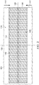
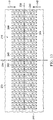
- FIG. 2 is a plan view, illustrating additional details that may be associated with some embodiments of the contact layer 110.
- the contact layer 110 may include a plurality of through-holes 140 or other perforations extending through the contact layer 110 to form walls 148.
- an exterior surface of the walls 148 may be parallel to sides of the contact layer 110.
- an interior surface of the walls 148 may be generally perpendicular to the tissue-facing surface 111 and the opposite surface 113 of the contact layer 110.
- the exterior surface or surfaces of the walls 148 may be coincident with the tissue-facing surface 111 and the opposite surface 113.
- the interior surface or surfaces of the walls 148 may form a perimeter 152 of each through-hole 140 and may connect the tissue facng surface 111 to the opposite surface 113.
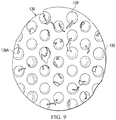
- the through-holes 140 may have a circular shape as shown.
- the through-holes 140 may have diameters between about 5 mm and about 20 mm, and in some embodiments, the diameters of the through-holes 140 may be about 10 mm.
- the through-holes 140 may have a depth that is about equal to the thickness 134 of the contact layer 110.
- the through-holes 140 may have a depth between about 6 mm to about 10 mm, and more specifically, about 8 mm at ambient pressure.
- the contact layer 110 may have a first orientation line 136 and a second orientation line 138 that is perpendicular to the first orientation line 136.
- the first orientation line 136 and the second orientation line 138 may be lines of symmetry of the contact layer 110.
- a line of symmetry may be, for example, an imaginary line across the tissue-facing surface 111 or the opposite surface 113 of the contact layer 110 defining a fold line such that if the contact layer 110 is folded on the line of symmetry, the through-holes 140 and walls 148 would be coincidentally aligned.
- the first orientation line 136 and the second orientation line 138 aid in the description of the contact layer 110.
- the first orientation line 136 and the second orientation line 138 may be used to refer to the desired directions of contraction of the contact layer 110.
- the desired direction of contraction may be parallel to the second orientation line 138 and perpendicular to the first orientation line 136.
- the desired direction of contraction may be parallel to the first orientation line 136 and perpendicular to the second orientation line 138.
- the desired direction of contraction may be at a non-perpendicular angle to both the first orientation line 136 and the second orientation line 138.
- the contact layer 110 may not have a desired direction of contraction.
- the contact layer 110 may be placed at the tissue site 103 so that the second orientation line 138 extends across the debris 130 of Figure 1 .
- the contact layer 110 is shown as having a generally rectangular shape including longitudinal edges 144 and latitudinal edges 146, the contact layer 110 may have other shapes.
- the contact layer 110 may have a diamond, square, or circular shape.
- the shape of the contact layer 110 may be selected to accommodate the type of tissue site being treated.
- the contact layer 110 may have an oval or circular shape to accommodate an oval or circular tissue site.
- the first orientation line 136 may be parallel to the longitudinal edges 144.
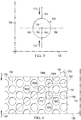
- the through-hole 140 may include a center 150 and a perimeter 152.
- the through-hole 140 may have a perforation shape factor (PSF).
- the perforation shape factor (PSF) may represent an orientation of the through-hole 140 relative to the first orientation line 136 and the second orientation line 138.
- the perforation shape factor (PSF) is a ratio of 1 ⁇ 2 a maximum length of the through-hole 140 that is parallel to the desired direction of contraction to 1 ⁇ 2 a maximum length of the through-hole 140 that is perpendicular to the desired direction of contraction.
- the desired direction of contraction is parallel to the second orientation line 138.
- the desired direction of contraction may be indicated by a lateral force 142.
- the through-hole 140 may have an X-axis 156 extending through the center 150 between opposing vertices of the hexagon and parallel to the first orientation line 136, and a Y-axis 154 extending through the center 150 between opposing sides of the hexagon and parallel to the second orientation line 138.
- the perforation shape factor (PSF) of the through-hole 140 may be defined as a ratio of a line segment 158 on the Y-axis 154 extending from the center 150 to the perimeter 152 of the through-hole 140, to a line segment 160 on the X-axis 156 extending from the center 150 to the perimeter 152 of the through-hole 140.
- the perforation shape factor (PSF) would be 1.
- the through-holes 140 may have other shapes and orientations, for example, oval, hexagonal, square, triangular, or amorphous or irregular and be oriented relative to the first orientation line 136 and the second orientation line 138 so that the perforation shape factor (PSF) may range from about 0.5 to about 1.10.
- the contact layer 110 may include the plurality of through-holes 140 aligned in parallel rows to form an array.
- the array of through-holes 140 may include a first row 162 of the through-holes 140, a second row 164 of the through-holes 140, and a third row 166 of the through-holes 140.
- a width of the wall 148 between the perimeters 152 of adjacent the through-holes 140 in a row, such as the first row 162 may be about 5 mm.
- the centers 150 of the through-holes 140 in adjacent rows may be characterized by being offset from the second orientation line 138 along the first orientation line 136.
- a line connecting the centers of adjacent rows may form a strut angle (SA) with the first orientation line 136.
- SA strut angle
- a first through-hole 140A in the first row 162 may have a center 150A
- a second through-hole 140B in the second row 164 may have a center 150B.
- a strut line 168 may connect the center 150A with the center 150B.
- the strut line 168 may form an angle 170 with the first orientation line 136.
- the angle 170 may be the strut angle (SA) of the contact layer 110.
- the strut angle (SA) may be less than about 90°. In other embodiments, the strut angle (SA) may be between about 30° and about 70° relative to the first orientation line 136. In other embodiments, the strut angle (SA) may be about 66° from the first orientation line 136. Generally, as the strut angle (SA) decreases, a stiffness of the contact layer 110 in a direction parallel to the first orientation line 136 may increase. Increasing the stiffness of the contact layer 110 parallel to the first orientation line 136 may increase the compressibility of the contact layer 110 perpendicular to the first orientation line 136.
- the contact layer 110 may be more compliant or compressible in a direction perpendicular to the first orientation line 136.
- the contact layer 110 may collapse to apply the lateral force 142 to the tissue site 103 described in more detail below.
- the centers 150 of the through-holes 140 in alternating rows may be spaced from each other parallel to the second orientation line 138 by a length 172.
- the length 172 may be greater than an effective diameter of the through-hole 140. If the centers 150 of through-holes 140 in alternating rows are separated by the length 172, the exterior surface of the walls 148 parallel to the first orientation line 136 may be considered continuous. Generally, exterior surface of the walls 148 may be continuous if the exterior surface of the walls 148 do not have any discontinuities or breaks between through-holes 140.
- the length 172 may be between about 7 mm and about 25 mm.
- the through-holes 140 in the contact layer 110 may leave void spaces in the contact layer 110 and on the tissue-facing surface 111 and the opposite surface 113 of the contact layer 110 so that only the exterior surface of the walls 148 of the contact layer 110 remain with a surface available to contact the tissue site 103. It may be desirable to minimize the exterior surface of the walls 148 so that the through-holes 140 may collapse, causing the contact layer 110 to collapse and generate the lateral force 142 in a direction perpendicular to the first orientation line 136. However, it may also be desirable not to minimize the exterior surface of the walls 148 so much that the contact layer 110 becomes too fragile for sustaining the application of a negative pressure.
- the void space percentage (VS) of the through-holes 140 may be equal to the percentage of the volume or surface area of the void spaces of the tissue-facing surface 111 created by the through-holes 140 to the total volume or surface area of the tissue-facing surface 111 of the contact layer 110. In some embodiments, the void space percentage (VS) may be between about 40% and about 75%. In other embodiments, the void space percentage (VS) may be about 55%.
- the organization of the through-holes 140 can also impact the void space percentage (VS), influencing the total surface area of the contact layer 110 that may contact the tissue site 103. In some embodiments, the longitudinal edge 144 and the latitudinal edge 146 of the contact layer 110 may be discontinuous.
- An edge may be discontinuous where the through-holes 140 overlap an edge causing the edge to have a non-linear profile.
- a discontinuous edge may reduce the disruption of keratinocyte migration and enhance re-epithelialization while negative pressure is applied to the dressing 102.
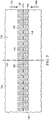
- the through-holes 140 of the contact layer 110 may have a depth that is less than the thickness 134 of the contact layer 110.
- the holes 140 may be blind holes formed in the tissue-facing surface 111 of the contact layer 110. The holes 140 may leave void spaces in the contact layer 110 on the tissue-facing surface 111 so that only the exterior surface of the walls 148 of the contact layer 110 on the tissue-facing surface 111 remain with a surface available to contact the tissue site 103 at ambient pressure.
- the void space percentage (VS) of the opposite surface 113 may be zero, while the void space percentage (VS) of the tissue-facing surface 111 is greater than zero, for example 55%.
- the holes 140 may be similar to and operate as described with respect to the through-holes 140, having similar structural, positional, and operational properties.
- the through-holes 140 may be formed during molding of the contact layer 110. In other embodiments, the through-holes 140 may be formed by cutting, melting, drilling, or vaporizing the contact layer 110 after the contact layer 110 is formed. For example, the through-holes 140 may be formed in the contact layer 110 by laser cutting the compressed foam of the contact layer 110. In some embodiments, the through-holes 140 may be formed so that the interior surfaces of the walls 148 of the through-holes 140 are parallel to the thickness 134. In other embodiments, the through-holes 140 may be formed so that the interior surfaces of the walls 148 of the through-holes 140 form a non-perpendicular angle with the tissue-facing surface 111.
- the interior surfaces of the walls 148 of the through-holes 140 may taper toward the center 150 of the through-holes 140 to form conical, pyramidal, or other irregular through-hole shapes. If the interior surfaces of the walls 148 of the through-holes 140 taper, the through-holes 140 may have a height less than the thickness 134 of the contact layer 110.
- formation of the through-holes 140 may thermoform the material of the contact layer 110, for example a compressed foam or a felted foam, causing the interior surface of the walls 148 extending between the tissue-facing surface 111 and the opposite surface 113 to be smooth.
- smoothness may refer to the formation of the through-holes 140 that causes the interior surface of the walls 148 that extends between the tissue-facing surface 111 and the opposite surface 113 to be substantially free of pores if compared to an uncut portion of the contact layer 110.
- laser-cutting the through-holes 140 into the contact layer 110 may plastically deform the material of the contact layer 110, closing any pores on the interior surfaces of the walls 148 that extend between the tissue-facing surface 111 and the opposite surface 113.
- a smooth interior surface of the walls 148 may limit or otherwise inhibit ingrowth of tissue into the contact layer 110 through the through-holes 140.
- the smooth interior surfaces of the walls 148 may be formed by a smooth material or a smooth coating.
- an effective diameter of the through-holes 140 may be selected to permit flow of particulates through the through-holes 140.
- the diameter of the through-holes 140 may be selected based on the size of the solubilized debris to be lifted from the tissue site 103. Larger through-holes 140 may allow larger debris to pass through the contact layer 110, and smaller through-holes 140 may allow smaller debris to pass through the contact layer 110 while blocking debris larger than the through-holes.
- successive applications of the dressing 102 can use contact layers 110 having successively smaller diameters of the through-holes 140 as the size of the solubilized debris in the tissue site 103 decreases.
- Sequentially decreasing diameters of the through-holes 140 may also aid in fine tuning a level of tissue disruption to the debris 130 during the treatment of the tissue site 103.
- the diameter of the through-holes 140 can also influence fluid movement in the contact layer 110 and the dressing 102.
- the contact layer 110 can channel fluid in the dressing 102 toward the through-holes 140 to aid in the disruption of the debris 130 on the tissue site 103.
- Variation of the diameters of the through-holes 140 can vary how fluid is moved through the dressing 102 with respect to both the removal of fluid and the application of negative pressure.
- the diameter of the through-holes 140 is between about 5 mm and about 20 mm and, more specifically, about 10 mm.
- An effective diameter of a non-circular area is defined as a diameter of a circular area having the same surface area as the non-circular area.
- each through-hole 140 may have an effective diameter of about 3.5 mm. In other embodiments, each through-hole 140 may have an effective diameter between about 5 mm and about 20 mm.
- the effective diameter of the through-holes 140 should be distinguished from the porosity of the material forming the walls 148 of the contact layer 110. Generally, an effective diameter of the through-holes 140 is an order of magnitude larger than the effective diameter of the pores of a material forming the contact layer 110.
- the effective diameter of the through-holes 140 may be larger than about 1 mm, while the walls 148 may be formed from GranuFoam® material having a pore size less than about 600 microns.
- the pores of the walls 148 may not create openings that extend all the way through the material.
- the through-holes 140 do not include pores formed by the foam formation process, and the through-holes 140 may have an average effective diameter that is greater than ten times an average effective diameter of pores of a material.
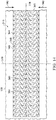
- the through-holes 140 may form a pattern depending on the geometry of the through-holes 140 and the alignment of the through-holes 140 between adjacent and alternating rows in the contact layer 110 with respect to the first orientation line 136. If the contact layer 110 is subjected to negative pressure, the through-holes 140 of the contact layer 110 may contract. As used herein, contraction can refer to both vertical compression of a body parallel to a thickness of the body, such as the contact layer 110, and lateral compression of a body perpendicular to a thickness of the body, such as the contact layer 110.
- the void space percentage (VS), the perforation shape factor (PSF), and the strut angle (SA) may cause the contact layer 110 to contract along the second orientation line 138 perpendicular to the first orientation line 136 as shown in more detail in Figure 5 . If the contact layer 110 is positioned on the tissue site 103, the contact layer 110 may generate the lateral force 142 along the second orientation line 138, contracting the contact layer 110, as shown in more detail in Figure 5 .
- the lateral force 142 may be optimized by adjusting the factors described above as set forth in Table 1 below.
- the through-holes 140 may be circular, have a strut angle (SA) of approximately 37°, a void space percentage (VS) of about 54%, a firmness factor (FF) of about 5, a perforation shape factor (PSF) of about 1, and a diameter of about 5 mm. If the contact layer 110 is subjected to a negative pressure of about -16.7 kPa (-125 mmHg), the contact layer 110 asserts the lateral force 142 of approximately 11.9 N.
- SA strut angle
- VS void space percentage
- FF firmness factor
- PSF perforation shape factor
- the through-holes 140 may be hexagonal, have a strut angle (SA) of approximately 66°, a void space percentage (VS) of about 55%, a firmness factor (FF) of about 5, a perforation shape factor (PSF) of about 1.07, and an effective diameter of about 5 mm.
- the lateral force 142 asserted by the contact layer 110 is about 13.3 N. If the effective diameter of the through-holes 140 of the contact layer 110 is increased to 10 mm, the lateral force 142 is decreased to about 7.5 N.
- the contact layer 110 is in the second position, or contracted position, as indicated by the lateral force 142.
- negative pressure is supplied to the sealed therapeutic environment 128 with the negative-pressure source 104.
- the contact layer 110 contracts from the relaxed position illustrated in Figure 2 to the contracted position illustrated in Figure 5 .
- the thickness 134 of the contact layer 110 remains substantially the same.
- the tissue-facing surface 111 of the contact layer 110 may disrupt the debris 130 on the tissue site 103 by rubbing the debris 130 from the tissue site 103.
- the edges of the through-holes 140 formed by the tissue-facing surface 111 and the interior surfaces or transverse surfaces of the walls 148 can form cutting edges that can disrupt the debris 130 in the tissue site 103, allowing the debris 130 to exit through the through-holes 140.
- the cutting edges are defined by the perimeter 152 where each through-hole 140 intersects the tissue-facing surface 111.
- the material, the void space percentage (VS), the firmness factor, the strut angle, the hole shape, the perforation shape factor (PSF), and the hole diameter may be selected to increase compression or collapse of the contact layer 110 in a lateral direction, as shown by the lateral force 142, by forming weaker walls 148.
- the factors may be selected to decrease compression or collapse of the contact layer 110 in a lateral direction, as shown by the lateral force 142, by forming stronger walls 148.
- the factors described herein can be selected to decrease or increase the compression or collapse of the contact layer 110 perpendicular to the lateral force 142.
- the therapy system 100 may provide cyclic therapy. Cyclic therapy may alternately apply negative pressure to and vent negative pressure from the sealed therapeutic environment 128. In some embodiments, negative pressure may be supplied to the sealed therapeutic environment 128 until the pressure in the sealed therapeutic environment 128 reaches a predetermined therapy pressure. If negative pressure is supplied to the sealed therapeutic environment 128, the debris 130 and the subcutaneous tissue 115 may be drawn into the through-holes 140. In some embodiments, the sealed therapeutic environment 128 may remain at the therapy pressure for a predetermined therapy period such as, for example, about 10 minutes. In other embodiments, the therapy period may be longer or shorter as needed to supply appropriate negative-pressure therapy to the tissue site 103.
- the sealed therapeutic environment 128 may be vented.
- the negative-pressure source 104 may fluidly couple the sealed therapeutic environment 128 to the atmosphere (not shown), allowing the sealed therapeutic environment 128 to return to ambient pressure.
- the negative-pressure source 104 may vent the sealed therapeutic environment 128 for about 1 minute.
- the negative-pressure source 104 may vent the sealed therapeutic environment 128 for longer or shorter periods. After venting of the sealed therapeutic environment 128, the negative-pressure source 104 may be operated to begin another negative-pressure therapy cycle.
- instillation therapy may be combined with negative-pressure therapy.
- the fluid source 120 may operate to provide fluid to the sealed therapeutic environment 128.
- the fluid source 120 may provide fluid while the negative-pressure source 104 vents the sealed therapeutic environment 128.
- the fluid source 120 may include a pump configured to move instillation fluid from the fluid source 120 to the sealed therapeutic environment 128.
- the fluid source 120 may not have a pump and may operate using a gravity feed system.
- the negative-pressure source 104 may not vent the sealed therapeutic environment 128. Instead, the negative pressure in the sealed therapeutic environment 128 is used to draw instillation fluid from the fluid source 120 into the sealed therapeutic environment 128.
- the fluid source 120 may provide a volume of fluid to the sealed therapeutic environment 128.
- the volume of fluid may be the same as a volume of the sealed therapeutic environment 128.
- the volume of fluid may be smaller or larger than the sealed therapeutic environment 128 as needed to appropriately apply instillation therapy.
- Instilling of the tissue site 103 may raise a pressure in the sealed therapeutic environment 128 to a pressure greater than the ambient pressure, for example to between about 0 Pa (0 mmHg) and about 2000 Pa (15 mmHg) and, more specifically, about 666.6 Pa (5 mmHg).
- the fluid provided by the fluid source 120 may remain in the sealed therapeutic environment 128 for a dwell time.
- the dwell time is about 5 minutes.
- the dwell time may be longer or shorter as needed to appropriately administer instillation therapy to the tissue site 103.
- the dwell time may be zero.
- the negative-pressure source 104 may be operated to draw the instillation fluid into the container 112, completing a cycle of therapy.
- negative pressure may also be supplied to the sealed therapeutic environment 128, starting another cycle of therapy.
- Figure 6 is a sectional view of a portion of the contact layer 110, illustrating additional details that may be associated with some embodiments.
- the contact layer 110 and the retainer layer 108 may be placed at the tissue site 103 having the debris 130 covering the subcutaneous tissue 115.
- the drape 106 may be placed over the retainer layer 108 to provide the sealed therapeutic environment 128 for the application of negative pressure therapy or instillation therapy.
- the retainer layer 108 may have a thickness 131 if the pressure in the sealed therapeutic environment 128 is about an ambient pressure. In some embodiments, the thickness 131 may be about 8 mm. In other embodiments, the thickness 131 may be about 16 mm.
- Figure 7 is a sectional view of a portion of the dressing 102 during negative-pressure therapy, illustrating additional details that may be associated with some embodiments.
- Figure 7 may illustrate a moment in time where a pressure in the sealed therapeutic environment 128 may be about 16.7 kPa (125 mmHg) of negative pressure.
- the retainer layer 108 may be a non-precompressed foam, and the contact layer 110 may be a precompressed foam.
- the contact layer 110 may not compress, and the retainer layer 108 may compress so that the manifold has a thickness 133.
- the thickness 133 of the retainer layer 108 during negative-pressure therapy may be less than the thickness 131 of the retainer layer 108 if the pressure in the sealed therapeutic environment 128 is about the ambient pressure.
- negative pressure in the sealed therapeutic environment 128 can generate concentrated stresses in the retainer layer 108 adjacent to the through-holes 140 in the contact layer 110.
- the concentrated stresses can cause macro-deformation of the retainer layer 108 that draws portions of the retainer layer 108 into the through-holes 140 of the contact layer 110.
- negative pressure in the sealed therapeutic environment 128 can generate concentrated stresses in the debris 130 adjacent to the through-holes 140 in the contact layer 110.
- the concentrated stresses can cause macro-deformations of the debris 130 and the subcutaneous tissue 115 that draws portions of the debris 130 and the subcutaneous tissue 115 into the through-holes 140.
- Figure 8 is a detail view of the contact layer 110, illustrating additional details of the operation of the contact layer 110 during negative-pressure therapy.
- Portions of the retainer layer 108 in contact with the opposite surface 113 of the contact layer 110 may be drawn into the through-holes 140 to form bosses 137.
- the bosses 137 may have a shape that corresponds to the through-holes 140.
- a height of the bosses 137 from the retainer layer 108 may be dependent on the pressure of the negative pressure in the sealed therapeutic environment 128, the area of the through-holes 140, and the firmness factor of the retainer layer 108.
- the through-holes 140 of the contact layer 110 may create macro-pressure points in portions of the debris 130 and the subcutaneous tissue 115 that are in contact with the tissue-facing surface 111 of the contact layer 110, causing tissue puckering and nodules 139 in the debris 130 and the subcutaneous tissue 115.
- a height of the nodules 139 over the surrounding tissue may be selected to maximize disruption of debris 130 and minimize damage to subcutaneous tissue 115 or other desired tissue.
- the pressure in the sealed therapeutic environment 128 can exert a force that is proportional to the area over which the pressure is applied.
- the force may be concentrated as the resistance to the application of the pressure is less than in the walls 148 of the contact layer 110.
- the debris 130 and the subcutaneous tissue 115 that forms the nodules 139 may be drawn into and through the through-holes 140 until the force applied by the pressure is equalized by the reactive force of the debris 130 and the subcutaneous tissue 115.
- the thickness 134 of the contact layer 110 may be selected to limit the height of the nodules 139 over the surrounding tissue.
- the retainer layer 108 may limit the height of the nodules 139 to the thickness 134 of the contact layer 110 under negative pressure if the contact layer is compressible.
- the bosses 137 of the retainer layer 108 may limit the height of the nodules 139 to a height that is less than the thickness 134 of the contact layer 110. By controlling the firmness factor of the retainer layer 108, the height of the bosses 137 over the surrounding material of the retainer layer 108 can be controlled.
- the height of the nodules 139 can be limited to the difference of the thickness 134 of the contact layer 110 and the height of the bosses 137. In some embodiments, the height of the bosses 137 can vary from zero to several millimeters as the firmness factor of the retainer layer 108 decreases. In an exemplary embodiment, the thickness 134 of the contact layer 110 may be about 7 mm. During the application of negative pressure, the bosses 137 may have a height between about 4 mm to about 5 mm, limiting the height of the nodules to about 2 mm to about 3 mm. By controlling the height of the nodules 139 by controlling the thickness 134 of the contact layer 110, the firmness factor of the retainer layer 108, or both, the aggressiveness of disruption to the debris 130 and tearing can be controlled.
- the height of the nodules 139 can also be controlled by controlling an expected compression of the contact layer 110 during negative-pressure therapy.
- the contact layer 110 may have a thickness 134 of about 8 mm. If the contact layer 110 is formed from a compressed foam, the firmness factor of the contact layer 110 may be higher; however, the contact layer 110 may still reduce in thickness in response to negative pressure in the sealed therapeutic environment 128.
- application of negative pressure of between about -6.7 kPa (-50 mmHg) and about -46.7 kPa (-350 mmHg), between about -13.3 kPa (-100 mmHg) and about -33.3 kPa (-250 mmHg) and, more specifically, about -16.7 kPa (-125 mmHg) in the sealed therapeutic environment 128 may reduce the thickness 134 of the contact layer 110 from about 8 mm to about 3 mm. If the retainer layer 108 is placed over the contact layer 110, the height of the nodules 139 may be limited to be no greater than the thickness 134 of the contact layer 110 during negative-pressure therapy, for example, about 3 mm. By controlling the height of the nodules 139, the forces applied to the debris 130 by the contact layer 110 can be adjusted and the degree that the debris 130 is stretched can be varied.
- the formation of the bosses 137 and the nodules 139 can cause the debris 130 to remain in contact with a tissue interface 107 during negative pressure therapy.
- the nodules 139 may contact the sidewalls of the through-holes 140 of the contact layer 110 and the bosses 137 of the retainer layer 108, while the surrounding tissue may contact the tissue-facing surface 111 of the contact layer 110.
- formation of the nodules 139 may lift debris and particulates off of the surrounding tissue, operating in a piston-like manner to move debris toward the retainer layer 108 and out of the sealed therapeutic environment 128.
- the debris 130 and the subcutaneous tissue 115 may leave the through-holes 140, returning to the position shown in Figure 6 .
- FIG. 9 is a top view of the debris 130, illustrating additional details that may be associated with some embodiments.
- the nodules 139 may rupture.
- the debris 130 in a nodule 139A may rupture, aiding in the removal of the debris 130.
- repeated application of negative-pressure therapy and instillation therapy while the contact layer 110 is disposed over the debris 130 may disrupt the debris 130, allowing the debris 130 to be removed during dressing changes.
- the contact layer 110 may disrupt the debris 130 so that the debris 130 can be removed by negative pressure.
- the contact layer 110 may disrupt the debris 130, aiding removal of the debris 130 during debridement processes.
- the contact layer 110 may form nodules 139 in the debris 130.
- the formation of the nodules 139 and release of the nodules 139 by the contact layer 110 during therapy may disrupt the debris 130.
- disruption of the debris 130 can be increased.
- Disruption of the debris 130 can be caused, at least in part, by the concentrated forces applied to the debris 130 by the through-holes 140 and the walls 148 of the contact layer 110.
- the forces applied to the debris 130 can be a function of the negative pressure supplied to the sealed therapeutic environment 128 and the area of each through-hole 140. For example, if the negative pressure supplied to the sealed therapeutic environment 128 is about 16.7 kPa (125 mmHg) and the diameter of each through-hole 140 is about 5 mm, the force applied at each through-hole 140 is about 0.31 N (0.07 lbf). If the diameter of each through-hole 140 is increased to about 8 mm, the force applied at each through-hole 140 can increase up to 6 times. Generally, the relationship between the diameter of each through-hole 140 and the applied force at each through-hole 140 is not linear and can increase exponentially with an increase in diameter.
- the negative pressure applied by the negative-pressure source 104 may be cycled rapidly. For example, negative pressure may be supplied for a few seconds, then vented for a few seconds, causing a pulsation of negative pressure in the sealed therapeutic environment 128. The pulsation of the negative pressure can pulsate the nodules 139, causing further disruption of the debris 130.
- the cyclical application of instillation therapy and negative pressure therapy may cause micro-floating.
- negative pressure may be applied to the sealed therapeutic environment 128 during a negative-pressure therapy cycle.
- instillation fluid may be supplied during the instillation therapy cycle.
- the instillation fluid may cause the contact layer 110 to float relative to the debris 130.
- the contact layer 110 may change position relative to the position the contact layer 110 occupied during the negative-pressure therapy cycle. The position change may cause the contact layer 110 to engage a slightly different portion of the debris 130 during the next negative-pressure therapy cycle, aiding disruption of the debris 130.
- the contact layer 110 may be bonded to the retainer layer 108.
- the retainer layer 108 may have a portion subjected to the compression or felting processes to form the contact layer 110.
- the plurality of through-holes 140 may then be formed or cut into the compressed foam portion of the retainer layer 108 to a depth for the desired height of the nodules 139.
- the retainer layer 108 may be a compressed or felted foam having the through-holes 140 formed in a portion of the retainer layer 108.
- the portions of the retainer layer 108 having the through-holes 140 may comprise the contact layer 110.
- the contact layer 110 may be provided as a component of a dressing kit.
- the kit may include a punch, and the contact layer 110 may be provided without any through-holes 140.
- the user may use the punch to place the through-holes 140 through portions of the contact layer 110 that may be placed over the debris 130.
- the kit provides a user, such as a clinician, the ability to customize the contact layer 110 to the particular tissue site 103, so that the through-holes 140 are only disrupting the debris 130 and not healthy tissue that may be near or surround the debris 130.
- the contact layer 110 can also be used with other foams without the through-holes 140.
- the contact layer 110 can be cut to fit the debris 130 at the tissue site 103, and dressing material without the through-holes 140 may be placed over remaining areas of the tissue site 103.
- other dressing materials may be placed between the contact layer 110 and the tissue site 103 where no disruption is desired.
- the kit may include a first retainer layer 108 having a thickness of between about 5 mm and about 15 mm and, more specifically, about 8 mm.
- the kit can also include a second retainer layer 108 having a thickness between about 10 mm and about 20 mm and, more specifically, about 16 mm.
- the user may select an appropriate one of the first retainer layer 108 and the second retainer layer 108 as needed to fill the tissue site 103.
- the contact layer 110 was evaluated on various matrices using a Dermosol wound model to simulate human tissue that allows contraction of the tissue during negative-pressure therapy.
- the matrices included a soluble Pectin matrix to simulate thick exudate or biofilm, a combination soluble and insoluble matrix to simulate slough and eschar, and an insoluble matrix, such as PrismaTM, to simulate robust devitalized tissue.
- the experimental results indicated that the contact layer 110 provided granulation and particle loss comparable to negative-pressure therapy with a foam manifold, such as Granufoam®, with decrease in peel force and bleeding.
- the experimental results provided consistent visual evidence of surface changes related to the pattern of the through-holes 140 that results in loosening and detachment of exudate and infectious material.
- each matrix was 5 cm in diameter and had a 1 cm depth. Each matrix was maintained at a controlled temperature using heated circulated water.
- the Pectin matrices were subjected to a single cycle, each having a 10 minute instillation soak period and 30 minute negative pressure therapy period lasting for an experimental time period of about 1 hour.
- the simulated eschar matrices were subjected to 10 cycles, each having a 20 minute instillation soak period and 45 minute negative pressure therapy period for an experimental time period of about 10 hours.
- the collagen matrices were subjected to 48 cycles, each having a 20 minute instillation soak period and a 45 minute negative pressure therapy period for an experimental time period of about 48 hours. As illustrated in Figure 10 , in each experimental case, softening and other disruption of debris occurred.
- the model used full thickness dorsal excisional wounds having a rectangular shape.
- the wounds were 3 cm x 7 cm in size on female domestic swine.
- the dressings used in the experimental model were changed every two to three days during a seven day study duration.
- Each animal included a control site dressed with a foam manifold, such as a Granufoam®, and saline instillation.
- Each animal had twelve tissue sites. 180 degree peel testing was conducted at each dressing change to determine the peel force required to remove the dressing and the amount of foam retention in the site.
- Histology was conducted at the termination of seven days to determine the granulation tissue thickness and to make a scored assessment of inflammation, abscess, and edema.
- the scored assessment used the following scale: 0 for the condition not being present, 1 for the condition being minimal, 2 for the condition being mild, 3 for the condition being moderate, 4 for the condition being marked, and 5 for the condition being severe.
- images were made of each tissue site at each dressing change to determine healing progression and the amount of retained foam. Treatment included a 10 minute instillation soak period, a 3.5 hour negative pressure therapy period at -16.7 kPa (-125 mmHg), and 6.5 therapy cycles were conducted per day.
- Six experimental dressing types were tested. The through-holes in the contact layer in two dressings were circular.
- the through-holes had 4mm diameters and 3 mm spacing between the perimeters of adjacent through-holes; in the second, the through-holes had 10 mm diameters and 5 mm spacing between the perimeters of adjacent through-holes.
- the through-holes in the contact layer in two dressings were hexagonal. In the first, the through-holes had 4 mm sides and 3mm spacing between the perimeters of adjacent through-holes. In the second, the through-holes had 10 mm sides and 5 mm spacing between the perimeters of adjacent through-holes.
- the through-holes in the contact layer in two dressings were ellipsoid. In the first, the through-holes had a 10 mm x 5 mm ellipse and small spacing, and in the second, the through-holes had a 5 mm x 10 mm ellipse and large spacing.
- the control group experienced an average of 5.1 Newtons (N) peel force on day 7 and maximum bleeding.
- Granulation tissue thickness was nominal, edema measured at 1.8, abscess at 0.5, and inflammation at 1.2.
- the average peel force was less than 5.1 N at day 3, day 5, and day 7.
- the total amount of blood loss for the experimental dressings was 50% of the blood loss for the control dressings at day 7.
- the histological scores for the experimental contact layers were less than 3.
- granulation tissue thickness for the experimental dressings was measured at between 3 mm and 5 mm, where the granulation tissue thickness in the control dressings was about 4 mm.
- FIG. 11 Disruption of debris associated with other experimental results is illustrated in Figure 11 and Figure 12 .
- a cellulose test matrix was treated with a contact layer having circular holes and a foam material.
- the portion treated with the contact layer having circular holes demonstrated disruption of debris on the tissue following treatment.
- the portion of the cellulose test matrix treated with a foam material experienced little to no disruption.
- Figure 12 illustrates a magnified view of the cellulose test matrix of Figure 11 showing the fibrous matrix having a thickened gel-like pulp. Following treatment with the contact layer, the fibrous matrix showed evidence of disruption including rupture of the matrix.
- Figure 13 is a plan view, illustrating additional details that may be associated with some embodiments of a contact layer 210.
- the contact layer 210 may be similar to the contact layer 110 and operate as described above with respect to Figures 1-9 . Similar elements may have similar numbers indexed to 200.
- the contact layer 210 is shown as having a generally rectangular shape including longitudinal edges 244 and latitudinal edges 246.
- the contact layer 210 may have a first orientation line 236 and a second orientation line 238 that is perpendicular to the first orientation line 236.
- the contact layer 210 may include a plurality of through-holes 240 or perforations extending through the contact layer 210 to from walls 248 that extend through the contact layer 210.
- the walls 248 may have interior or transverse surfaces that intersect with the tissue-facing surface 211 to form cutting edges.
- the through-holes 240 may have a hexagonal shape as shown.
- Figure 14 is a plan view, illustrating additional details that may be associated with some embodiments of a contact layer 310.
- the contact layer 310 may be similar to the contact layer 110 and operate as described above with respect to Figures 1-9 . Similar elements may have similar reference numbers indexed to 300.
- the contact layer 310 may have a first orientation line 336 and a second orientation line 338 that is perpendicular to the first orientation line 336.
- the contact layer 310 may include a plurality of through-holes 340 or perforations extending through the contact layer 310 to form walls 348 that extend through the contact layer 310.
- the walls 348 may have interior surfaces or transverse surfaces that intersect with the tissue-facing surface 311 to form cutting edges.
- the through-holes 340 may have an ovoid shape as shown.
- Figure 15 is a plan view, illustrating additional details that may be associated with some embodiments of a contact layer 410.
- the contact layer 410 may be similar to the contact layer 110 and operate as described with respect to Figures 1-9 . Similar elements may have similar reference numbers indexed to 400.
- the contact layer 410 is shown as having a generally rectangular shape including longitudinal edges 444 and latitudinal edges 446.
- the contact layer 410 may have a first orientation line 436 and a second orientation line 438 that is perpendicular to the first orientation line 436.
- the contact layer 410 may include a plurality of through-holes 440 or perforations extending through the contact layer 410 to form walls 448 that extend through the contact layer 410.
- the walls 448 may have interior surfaces or transverse surfaces that intersect with the tissue-facing surface 411 to form cutting edges.
- the through-holes 440 may have a triangular shape as shown.
- the through-holes 240, the through-holes 340, and the through-holes 440 of each of the contact layer 210, the contact layer 310, and the contact layer 410 may generate concentrated stresses that influence disruption of the debris 130 in different ways.
- the triangular shaped through-holes 440 of the contact layer 410 may focus the stresses of the contact layer 410 at vertices of the through-holes 440 so that disruption of the debris 130 may be focused at the vertices of the through-holes 440.
- the different shapes of the through-holes 240 and the through-holes 340 may also focus the stresses generated by the contact layer 210 and the contact layer 310 in other advantageous areas.
- a lateral force, such as the lateral force 142, generated by a contact layer, such as the contact layer 110, may be related to a compressive force generated by applying negative pressure at a therapy pressure to a sealed therapeutic environment.
- the lateral force 142 may be proportional to a product of a therapy pressure (TP) in the sealed therapeutic environment 128, the compressibility factor (CF) of the contact layer 110, and a surface area (A) the tissue-facing surface 111 of the contact layer 110.
- TP therapy pressure
- CF compressibility factor
- A surface area
- the therapy pressure TP is measured in N/m 2
- the compressibility factor (CF) is dimensionless
- the area (A) is measured in m 2
- the lateral force is measured in Newtons (N).
- the compressibility factor (CF) resulting from the application of negative pressure to a contact layer may be, for example, a dimensionless number that is proportional to the product of the void space percentage (VS) of a contact layer, the firmness factor (FF) of the contact layer, the strut angle (SA) of the through-holes in the contact layer, and the perforation shape factor (PSF) of the through-holes in the contact layer.
- the relationship is expressed as follows: Compressibility Factor CF ⁇ VS ⁇ FF ⁇ sin SA ⁇ PSF
- contact layers formed from different materials with through-holes of different shapes were manufactured and tested to determine the lateral force of the contact layers.
- the therapy pressure TP was about -16.7 kPa (-125 mmHg) and the dimensions of the contact layer were about 200 mm by about 53 mm so that the surface area (A) of the tissue-facing surface of the contact layer was about 106 cm 2 or 0.0106 m 2 .
- the lateral force for a Supracor® contact layer 210 having a firmness factor (FF) of 3 was about 13.3 where the Supracor® contact layer 210 had hexagonal through-holes 240 with a distance between opposite vertices of 5 mm, a perforation shape factor (PSF) of 1.07, a strut angle (SA) of approximately 66°, and a void space percentage (VS) of about 55%.
- a similarly dimensioned GranuFoam® contact layer 110 generated the lateral force 142 of about 9.1 Newtons (N). TABLE 1 Material VS FF SA Hole Shape PSF Major diam.
- the formulas described above may not precisely describe the lateral forces due to losses in force due to the transfer of the force from the contact layer to the wound.
- the modulus and stretching of the drape 106, the modulus of the tissue site 103, slippage of the drape 106 over the tissue site 103, and friction between the contact layer 110 and the tissue site 103 may cause the actual value of the lateral force 142 to be less than the calculated value of the lateral force 142.
- Figure 16 is a flow chart 1600 illustrating exemplary operations that can be associated with some embodiments of the therapy system 100 of Figure 1 .
- the contact layer 110 may be selected for use on the tissue site 103.
- the selected contact layer can be positioned at a tissue site.
- the contact layer 110 can be positioned over the debris 130 of the tissue site 103.
- a retainer layer may be selected for use on the tissue site.
- the retainer layer 108 can be selected for use on the tissue site 103.
- the selected retainer layer can be positioned over the contact layer.
- the retainer layer 108 can be positioned over the contact layer 110.
- a sealing member may be positioned over the retainer layer, the contact layer, and the tissue site, and at block 1611, the sealing member can be sealed to tissue surrounding the tissue site.
- the drape 106 can be positioned over the tissue site 103 and sealed to tissue surrounding the tissue site 103.
- a negative pressure source can be fluidly coupled to a sealed space formed by the sealing member.
- the negative-pressure source 104 can be fluidly coupled to the sealed therapeutic environment 128 formed by the drape 106.
- the negative-pressure source can supply negative pressure to the sealed space.
- a controller of the negative-pressure source 104 can actuate the negative-pressure source 104 to draw fluid from the sealed therapeutic environment 128, thereby supplying negative-pressure to the sealed therapeutic environment 128 for a negative-pressure therapy period.
- the controller can determine if the negative-pressure therapy period has concluded. For example, a controller of the negative-pressure source 104 can determine if a timer, started when the negative-pressure source was actuated to supply negative pressure, has reached a predetermined time. The predetermined time may be based on an expected timer interval for negative-pressure therapy of the predetermined time may be a time period selected by a user. At block 1617, if the timer has not expired, the method can continue on the NO path to block 1615, where the controller of the negative-pressure source can continue supplying negative pressure to the sealed space.
- the method can continue on the YES path to block 1619, where the controller of the negative-pressure source can vent the negative pressure in the sealed space to the ambient environment.
- the controller of the negative-pressure source 104 can vent the sealed therapeutic environment 128 to the ambient environment.
- the method determines if therapy has concluded.
- the controller of the negative-pressure source 104 can determine if a predetermined number of supply and vent cycles has been completed.
- the predetermined number of supply and vent cycles can be a standard number of cycles for therapy or can be a number of cycles entered in by a user. If therapy has not concluded, the method can continue on the NO path to block 1615, where the negative-pressure source can be operated to supply negative pressure to the sealed space. If therapy has concluded, the method can continue on the YES path, where the method ends.
- FIG 17 is a flow chart 1700 illustrating exemplary operations that can be associated with some embodiments of the therapy system 100 of Figure 1 .
- operations may be implemented by a controller in a negative-pressure source, such as the negative-pressure source 104, configured to execute the operations.
- Operations may also be performed by a user, such as a clinician.
- a user may examine a tissue site.
- a clinician may examine the tissue site 103.
- the user may determine, based on the user's examination, a status of the debris of the tissue site.
- a clinician may determine that the debris 130 covers the tissue site 103.
- the status determination can also include: a thickness of the debris 130, a consistency of the debris 130, a color of the debris 130, and a moisture level of the debris 130.
- the clinician may determine that the debris 130 at the tissue site 103 may have a thin, thick, runny, solid, rough, firm, smooth, heavy, or light consistency.
- the clinician may determine that the debris 130 at the tissue site 103 has a black, red, brown, green, yellow, gray, or other color that is indicative of a state of infection of the debris 130.
- the clinician can also determine how moist the debris 130 at the tissue site 103 is on a scale ranging from no presence of liquid to saturated. In some embodiments, the determination of a moisture level aids a clinician in understanding how much exudate is present in the tissue site 103.
- the user may determine other parameters influencing treatment.
- the clinician can determine a patient's pain tolerance, environment, preference, age, co-morbidities, quality of life, caregiver resources, and caregiver skills.
- the user can determine the desired targets for treatment of the debris at the tissue site. For example, the clinician can determine if the debris 130 comprises necrotic tissue, eschar, impaired tissue, other sources of infection, exudate, slough including hyperkeratosis, pus, foreign bodies, biofilm, or other types of bioburden. The clinician can also determine if treatment will reduce unpleasant odors, excess moisture, and the risk of infection of the debris 130 and the tissue site 103.
- the user can select a contact layer having a firmness factor, a thickness, a through-hole shape, a through-hole size, and an array pattern to achieve the desired targets for treatment.
- the clinician may select the contact layer 110 to have the thickness 134 greater than the thickness determine at block 1703.
- the clinician can also select the contact layer 110 having circular through-holes 140 to permit the flow of the debris 130 having a yellowish color, a thick consistency, and a high moisture level.
- the clinician can further select a contact layer 110 having the through-holes 140 having a diameter greater than a size of the largest solubilized debris 130 in the tissue site 103.
- the clinician may select a contact layer 110 having triangular through-holes 140, for example, if the debris 130 is rough, black, and has a low moisture content.
- the user can select a retainer layer.
- the clinician can select the retainer layer 108 having a firmness factor and a thickness.
- the thickness of the retainer layer 108 may be selected to fill the tissue site 103.
- the clinician may select the firmness factor of the retainer layer 108 to limit the height of the nodules 139. For example, if the debris 130 is thinner than the contact layer 110, has a runny consistency, and has a smooth surface, the clinician may select a retainer layer 108 having a low firmness factor.
- a lower firmness factor of the retainer layer 108 may permit the bosses 137 to have a larger height than a retainer layer 108 having a high firmness factor, thereby decreasing the height of the nodules 139.
- the user may conduct treatment with contact layer.
- the clinician may conduct treatment with the contact layer 110 and the therapy system 100, after which the method concludes.
- the systems, apparatuses, and exemplary methods described herein may provide significant advantages. For example, combining the mechanical rubbing action of a contact layer with the hydrating and flushing action of instillation and negative-pressure therapy may enable low or no pain debridement of a tissue site.
- a contact layer as described herein may also require less monitoring from a clinician or other attendant as compared to other mechanical debridement processes and enzymatic debridement processes.
- contact layers as described herein may not become blocked by removed necrotic tissue as may occur during autolytic debridement of a tissue site.
- the contact layers described herein can aid in removal of necrosis, eschar, impaired tissue, sources of infection, exudate, slough including hyperkeratosis, pus, foreign bodies, debris, and other types of bioburden or barriers to healing.
- the contact layers can also decrease odor, excess wound moisture, and the risk of infection while stimulating edges of a tissue site and epithelialization.
- the contact layers described herein can also provide improved removal of thick exudate, allow for earlier placement of instillation and negative-pressure therapy devices, may limit or prevent the use of other debridement processes, and can be used on tissue sites that are difficult to debride.
- the therapy system may be used in conjunction with other tissue removal and debridement techniques.
- the therapy system may be used prior to enzymatic debridement to soften the debris.
- mechanical debridement may be used to remove a portion of the debris a the tissue site, and the therapy system may then be used to remove the remaining debris while reducing the risk of trauma to the tissue site.
Landscapes
- Health & Medical Sciences (AREA)
- Heart & Thoracic Surgery (AREA)
- Life Sciences & Earth Sciences (AREA)
- Engineering & Computer Science (AREA)
- Public Health (AREA)
- Animal Behavior & Ethology (AREA)
- General Health & Medical Sciences (AREA)
- Biomedical Technology (AREA)
- Veterinary Medicine (AREA)
- Surgery (AREA)
- Vascular Medicine (AREA)
- Hematology (AREA)
- Anesthesiology (AREA)
- Medical Informatics (AREA)
- Nuclear Medicine, Radiotherapy & Molecular Imaging (AREA)
- Molecular Biology (AREA)
- Orthopedic Medicine & Surgery (AREA)
- Mechanical Engineering (AREA)
- Otolaryngology (AREA)
- Oral & Maxillofacial Surgery (AREA)
- Pulmonology (AREA)
- Media Introduction/Drainage Providing Device (AREA)
- Surgical Instruments (AREA)
Priority Applications (1)
| Application Number | Priority Date | Filing Date | Title |
|---|---|---|---|
| EP20204773.4A EP3791837A1 (en) | 2014-05-09 | 2015-05-08 | Disruptive dressing for use with negative pressure and fluid instillation |
Applications Claiming Priority (5)
| Application Number | Priority Date | Filing Date | Title |
|---|---|---|---|
| US201461991150P | 2014-05-09 | 2014-05-09 | |
| US201461991134P | 2014-05-09 | 2014-05-09 | |
| US201461991174P | 2014-05-09 | 2014-05-09 | |
| PCT/US2015/030030 WO2015172111A1 (en) | 2014-05-09 | 2015-05-08 | Disruptive dressing for use with negative pressure and fluid instillation |
| EP15724881.6A EP3139880B1 (en) | 2014-05-09 | 2015-05-08 | Disruptive dressing for use with negative pressure and fluid instillation |
Related Parent Applications (1)
| Application Number | Title | Priority Date | Filing Date |
|---|---|---|---|
| EP15724881.6A Division EP3139880B1 (en) | 2014-05-09 | 2015-05-08 | Disruptive dressing for use with negative pressure and fluid instillation |
Related Child Applications (2)
| Application Number | Title | Priority Date | Filing Date |
|---|---|---|---|
| EP20204773.4A Division-Into EP3791837A1 (en) | 2014-05-09 | 2015-05-08 | Disruptive dressing for use with negative pressure and fluid instillation |
| EP20204773.4A Division EP3791837A1 (en) | 2014-05-09 | 2015-05-08 | Disruptive dressing for use with negative pressure and fluid instillation |
Publications (2)
| Publication Number | Publication Date |
|---|---|
| EP3354241A1 EP3354241A1 (en) | 2018-08-01 |
| EP3354241B1 true EP3354241B1 (en) | 2020-12-30 |
Family
ID=53267628
Family Applications (3)
| Application Number | Title | Priority Date | Filing Date |
|---|---|---|---|
| EP15724881.6A Active EP3139880B1 (en) | 2014-05-09 | 2015-05-08 | Disruptive dressing for use with negative pressure and fluid instillation |
| EP18162504.7A Active EP3354241B1 (en) | 2014-05-09 | 2015-05-08 | Disruptive dressing for use with negative pressure and fluid instillation |
| EP20204773.4A Pending EP3791837A1 (en) | 2014-05-09 | 2015-05-08 | Disruptive dressing for use with negative pressure and fluid instillation |
Family Applications Before (1)
| Application Number | Title | Priority Date | Filing Date |
|---|---|---|---|
| EP15724881.6A Active EP3139880B1 (en) | 2014-05-09 | 2015-05-08 | Disruptive dressing for use with negative pressure and fluid instillation |
Family Applications After (1)
| Application Number | Title | Priority Date | Filing Date |
|---|---|---|---|
| EP20204773.4A Pending EP3791837A1 (en) | 2014-05-09 | 2015-05-08 | Disruptive dressing for use with negative pressure and fluid instillation |
Country Status (7)
| Country | Link |
|---|---|
| US (3) | US9918733B2 (zh) |
| EP (3) | EP3139880B1 (zh) |
| JP (2) | JP6640114B2 (zh) |
| CN (2) | CN106413594B (zh) |
| AU (2) | AU2015255726B2 (zh) |
| CA (1) | CA2948170C (zh) |
| WO (1) | WO2015172111A1 (zh) |
Families Citing this family (84)
| Publication number | Priority date | Publication date | Assignee | Title |
|---|---|---|---|---|
| GB0808376D0 (en) | 2008-05-08 | 2008-06-18 | Bristol Myers Squibb Co | Wound dressing |
| GB0817796D0 (en) | 2008-09-29 | 2008-11-05 | Convatec Inc | wound dressing |
| GB201020236D0 (en) | 2010-11-30 | 2011-01-12 | Convatec Technologies Inc | A composition for detecting biofilms on viable tissues |
| CA2819475C (en) | 2010-12-08 | 2019-02-12 | Convatec Technologies Inc. | Integrated system for assessing wound exudates |
| CA2819549C (en) | 2010-12-08 | 2019-09-10 | Convatec Technologies Inc. | Wound exudate system accessory |
| US9421132B2 (en) | 2011-02-04 | 2016-08-23 | University Of Massachusetts | Negative pressure wound closure device |
| EP2723286B2 (en) | 2011-06-24 | 2021-10-13 | KCI Licensing, Inc. | Reduced-pressure dressings employing tissue-fixation elements |
| GB201115182D0 (en) | 2011-09-02 | 2011-10-19 | Trio Healthcare Ltd | Skin contact material |
| GB2497406A (en) | 2011-11-29 | 2013-06-12 | Webtec Converting Llc | Dressing with a perforated binder layer |
| GB201120693D0 (en) | 2011-12-01 | 2012-01-11 | Convatec Technologies Inc | Wound dressing for use in vacuum therapy |
| MX2014014325A (es) | 2012-05-24 | 2015-08-06 | Smith & Nephew Inc | Dispositivos y metodos para tratar y cerrar heridas con presion negativa. |
| CN104812343B (zh) | 2012-07-16 | 2019-06-18 | 史密夫和内修有限公司 | 负压伤口闭合设备 |
| CN105008611A (zh) | 2012-12-20 | 2015-10-28 | 康沃特克科技公司 | 化学改性的纤维素纤维的处理 |
| CN113730099A (zh) | 2013-03-13 | 2021-12-03 | 史密夫和内修有限公司 | 负压伤口封闭装置以及用于以负压处理伤口的系统和方法 |
| GB201414146D0 (en) * | 2014-08-08 | 2014-09-24 | Medtrade Products Ltd | Wound dressing |
| GB201414147D0 (en) * | 2014-08-08 | 2014-09-24 | Medtrade Products Ltd | Wound dressing |
| JP6743050B2 (ja) | 2015-04-27 | 2020-08-19 | スミス アンド ネフュー ピーエルシーSmith & Nephew Public Limited Company | 減圧装置および方法 |
| US11439539B2 (en) | 2015-04-29 | 2022-09-13 | University Of Massachusetts | Negative pressure wound closure device |
| AU2016382963B2 (en) * | 2015-12-29 | 2021-12-09 | Solventum Intellectual Properties Company | System and methods for treatment of wounds with negative pressure and peroxy pyruvic acid |
| CA3016484A1 (en) | 2016-03-07 | 2017-09-14 | Smith & Nephew Plc | Wound treatment apparatuses and methods with negative pressure source integrated into wound dressing |
| US11167074B2 (en) | 2016-03-17 | 2021-11-09 | Kcl Licensing, Inc. | Systems and methods for treating a tissue site using one manifold and multiple therapy units |
| MX2018011801A (es) | 2016-03-30 | 2019-12-16 | Convatec Technologies Inc | Deteccion de infecciones microbianas en heridas. |
| CN109564213B (zh) | 2016-03-30 | 2023-01-31 | 西诺福有限公司 | 检测伤口微生物感染 |
| AU2017256692B2 (en) | 2016-04-26 | 2022-03-03 | Smith & Nephew Plc | Wound dressings and methods of use with integrated negative pressure source having a fluid ingress inhibition component |
| CA3038206A1 (en) | 2016-05-03 | 2017-11-09 | Smith & Nephew Plc | Optimizing power transfer to negative pressure sources in negative pressure therapy systems |
| WO2017191158A1 (en) | 2016-05-03 | 2017-11-09 | Smith & Nephew Plc | Systems and methods for driving negative pressure sources in negative pressure therapy systems |
| EP3452129B1 (en) | 2016-05-03 | 2022-03-23 | Smith & Nephew plc | Negative pressure wound therapy device activation and control |
| PL3481360T3 (pl) | 2016-07-08 | 2022-05-02 | Convatec Technologies Inc. | Wykrywanie przepływu płynu |
| EP3481348A4 (en) | 2016-07-08 | 2020-02-26 | ConvaTec Technologies Inc. | FLUID COLLECTION APPARATUS |
| AU2017292881B2 (en) | 2016-07-08 | 2022-03-17 | Convatec Technologies Inc. | Flexible negative pressure system |
| EP3503857B1 (en) | 2016-08-25 | 2024-04-17 | Smith & Nephew plc | Absorbent negative pressure wound therapy dressing |
| CN109640903A (zh) | 2016-08-30 | 2019-04-16 | 史密夫及内修公开有限公司 | 用于施加减压疗法的系统 |
| US11564847B2 (en) | 2016-09-30 | 2023-01-31 | Smith & Nephew Plc | Negative pressure wound treatment apparatuses and methods with integrated electronics |
| CN110167495B (zh) * | 2016-11-02 | 2022-06-14 | 史密夫和内修有限公司 | 伤口闭合设备 |
| CN110267630B (zh) * | 2017-01-09 | 2021-12-28 | 3M创新知识产权公司 | 用于改善流体移除的伤口敷料层 |
| AU2018229808B2 (en) | 2017-03-08 | 2024-04-11 | Smith & Nephew Plc | Negative pressure wound therapy device control in presence of fault condition |
| WO2018206420A1 (en) | 2017-05-09 | 2018-11-15 | Smith & Nephew Plc | Redundant controls for negative pressure wound therapy systems |
| EP3634339B1 (en) | 2017-06-07 | 2022-07-27 | 3M Innovative Properties Company | Peel and place dressing for negative-pressure therapy |
| US11179512B2 (en) * | 2017-06-07 | 2021-11-23 | Kci Licensing, Inc. | Multi-layer wound filler for extended wear time |
| WO2018226705A1 (en) | 2017-06-07 | 2018-12-13 | Kci Licensing, Inc. | Composite dressings for improved granulation and reduced maceration with negative-pressure treatment |
| RU2019139918A (ru) * | 2017-06-07 | 2021-07-09 | Кейсиай ЛАЙСЕНСИНГ, ИНК. | Отслаиваемый и размещаемый на месте перевязочный материал для густого экссудата и инстилляции |
| WO2018226687A1 (en) | 2017-06-07 | 2018-12-13 | Kci Licensing, Inc. | Methods for manufacturing and assembling dual material tissue interface for negative-pressure therapy |
| WO2018226650A1 (en) | 2017-06-07 | 2018-12-13 | Kci Licensing, Inc. | Systems, apparatuses, and methods for negative-pressure treatment with reduced tissue in-growth |
| AU2018282159A1 (en) | 2017-06-07 | 2019-12-19 | 3M Innovative Properties Company | Composite dressings for improved granulation and reduced maceration with negative-pressure treatment |
| RU2019142454A (ru) | 2017-06-07 | 2021-07-12 | Кейсиай ЛАЙСЕНСИНГ, ИНК. | Композитные перевязочные материалы для улучшенной грануляции и сниженной мацерации для лечения посредством отрицательного давления |
| AU2018280130A1 (en) | 2017-06-07 | 2019-12-19 | 3M Innovative Properties Company | Composite dressings for improved granulation reduced maceration with negative-pressure treatment |
| EP3634337B1 (en) | 2017-06-07 | 2023-05-24 | 3M Innovative Properties Company | Methods for manufacturing and assembling dual material tissue interface for negative-pressure therapy |
| CN110996867A (zh) * | 2017-06-12 | 2020-04-10 | 凯希特许有限公司 | 发泡且纹理化的烧结聚合物伤口填料 |
| US11123476B2 (en) * | 2017-06-14 | 2021-09-21 | Smith & Nephew, Inc. | Fluid removal management and control of wound closure in wound therapy |
| JP7394746B2 (ja) | 2017-09-13 | 2023-12-08 | スミス アンド ネフュー ピーエルシー | 一体化された電子機器を備えた陰圧創傷治療装置及び方法 |
| GB201718070D0 (en) | 2017-11-01 | 2017-12-13 | Smith & Nephew | Negative pressure wound treatment apparatuses and methods with integrated electronics |
| US11850124B2 (en) | 2017-10-24 | 2023-12-26 | 3M Innovative Properties Company | Debridement wound dressings and systems and methods using the same |
| GB201718072D0 (en) | 2017-11-01 | 2017-12-13 | Smith & Nephew | Negative pressure wound treatment apparatuses and methods with integrated electronics |
| GB201718054D0 (en) | 2017-11-01 | 2017-12-13 | Smith & Nephew | Sterilization of integrated negative pressure wound treatment apparatuses and sterilization methods |
| US11497653B2 (en) | 2017-11-01 | 2022-11-15 | Smith & Nephew Plc | Negative pressure wound treatment apparatuses and methods with integrated electronics |
| US11771599B2 (en) | 2017-11-03 | 2023-10-03 | Kci Licensing, Inc. | Extended wear-time dressing |
| CN111670022A (zh) * | 2018-01-04 | 2020-09-15 | 凯希特许有限公司 | 用于浓稠渗出物和滴注物的剥离与放置敷料 |
| EP3749268A1 (en) * | 2018-02-05 | 2020-12-16 | 3M Innovative Properties Company | Dressing for disruption of debris at a tissue site |
| WO2019157466A1 (en) | 2018-02-12 | 2019-08-15 | Healyx Labs, Inc. | Negative pressure wound therapy systems, devices, and methods |
| EP3755290B1 (en) * | 2018-02-23 | 2023-06-21 | 3M Innovative Properties Company | Dressing with bolster for linear tissue sites |
| EP3784182A1 (en) * | 2018-04-23 | 2021-03-03 | KCI Licensing, Inc. | Dressing providing apertures with multiple orifice sizes for negative-pressure therapy |
| EP3836872A1 (en) * | 2018-08-13 | 2021-06-23 | KCI Licensing, Inc. | Disruptive dressing for use with negative pressure and fluid instillation |
| CN112912117A (zh) * | 2018-09-12 | 2021-06-04 | 凯希特许有限公司 | 采用滴注治疗和动态压力控制的伤口治疗系统 |
| USD898925S1 (en) | 2018-09-13 | 2020-10-13 | Smith & Nephew Plc | Medical dressing |
| EP3876886B1 (en) * | 2018-11-08 | 2023-09-27 | 3M Innovative Properties Company | Dressing with protruding layer allowing for cleansing of wound bed macro deformations |
| EP3876885B1 (en) * | 2018-11-08 | 2023-11-29 | 3M Innovative Properties Company | Wound dressing with semi-rigid support to increase disruption using perforated dressing and negative pressure wound therapy |
| US20200146899A1 (en) * | 2018-11-09 | 2020-05-14 | Kci Licensing, Inc. | Hybrid adhesive tissue cover |
| EP3893825A1 (en) | 2018-12-13 | 2021-10-20 | University of Massachusetts | Negative pressure wound closure devices and methods |
| US20220072217A1 (en) | 2018-12-21 | 2022-03-10 | Systagenix Wound Management, Limited | Wound dressing material for visual indication of wound protease activity |
| CN113795225A (zh) * | 2019-05-08 | 2021-12-14 | 凯希特许有限公司 | 用于负压治疗的具有生物活性物质的歧管 |
| US20220218530A1 (en) | 2019-05-24 | 2022-07-14 | Kci Licensing, Inc. | Perforated Collagen Wound Interface For Use With Negative Pressure Wound Therapy |
| CN114340571A (zh) * | 2019-06-28 | 2022-04-12 | 凯希特许有限公司 | 具有聚合物递送的敷料 |
| EP4048335A1 (en) * | 2019-10-21 | 2022-08-31 | KCI Licensing, Inc. | Fluid bridge configured for use vertically and/or under compression |
| US11833290B2 (en) * | 2019-11-01 | 2023-12-05 | Kci Licensing, Inc. | Dressing design incorporating formed 3D textile for the delivery of therapeutic negative pressure and compressive forces to a treatment site |
| WO2021090276A1 (en) | 2019-11-07 | 2021-05-14 | Kci Licensing, Inc. | Means to reduce pressure reduction experienced with a collagen foam interface layer |
| WO2021111354A1 (en) * | 2019-12-04 | 2021-06-10 | Kci Licensing, Inc. | Tissue interface for negative-pressure and instillation therapy |
| US11331221B2 (en) | 2019-12-27 | 2022-05-17 | Convatec Limited | Negative pressure wound dressing |
| US11771819B2 (en) | 2019-12-27 | 2023-10-03 | Convatec Limited | Low profile filter devices suitable for use in negative pressure wound therapy systems |
| US11160917B2 (en) * | 2020-01-22 | 2021-11-02 | J&M Shuler Medical Inc. | Negative pressure wound therapy barrier |
| EP4132440A1 (en) * | 2020-05-05 | 2023-02-15 | KCI Licensing, Inc. | Tissue interface for negative pressure and instillation therapy |
| WO2022003463A1 (en) | 2020-07-01 | 2022-01-06 | Kci Licensing, Inc. | Non-silver wound instillation fluid with bio-film reduction properties |
| CN116367800A (zh) * | 2020-07-30 | 2023-06-30 | 3M创新知识产权公司 | 低向内生长组织界面 |
| JP2023551974A (ja) * | 2020-12-07 | 2023-12-13 | ケーシーアイ マニュファクチャリング アンリミテッド カンパニー | 透明な特性を有する伸縮可能な深さのドレッシング |
| WO2022234444A1 (en) | 2021-05-06 | 2022-11-10 | Kci Manufacturing Unlimited Company | Bio-absorbable dispersible rapidly deployable wound interface |
Family Cites Families (181)
| Publication number | Priority date | Publication date | Assignee | Title |
|---|---|---|---|---|
| US1355846A (en) | 1920-02-06 | 1920-10-19 | David A Rannells | Medical appliance |
| US2547758A (en) | 1949-01-05 | 1951-04-03 | Wilmer B Keeling | Instrument for treating the male urethra |
| US2632443A (en) | 1949-04-18 | 1953-03-24 | Eleanor P Lesher | Surgical dressing |
| GB692578A (en) | 1949-09-13 | 1953-06-10 | Minnesota Mining & Mfg | Improvements in or relating to drape sheets for surgical use |
| US2682873A (en) | 1952-07-30 | 1954-07-06 | Johnson & Johnson | General purpose protective dressing |
| NL189176B (nl) | 1956-07-13 | 1900-01-01 | Hisamitsu Pharmaceutical Co | Pleister op basis van een synthetische rubber. |
| US2969057A (en) | 1957-11-04 | 1961-01-24 | Brady Co W H | Nematodic swab |
| US3066672A (en) | 1960-09-27 | 1962-12-04 | Jr William H Crosby | Method and apparatus for serial sampling of intestinal juice |
| US3367332A (en) | 1965-08-27 | 1968-02-06 | Gen Electric | Product and process for establishing a sterile area of skin |
| US3520300A (en) | 1967-03-15 | 1970-07-14 | Amp Inc | Surgical sponge and suction device |
| US3568675A (en) | 1968-08-30 | 1971-03-09 | Clyde B Harvey | Fistula and penetrating wound dressing |
| US3682180A (en) | 1970-06-08 | 1972-08-08 | Coilform Co Inc | Drain clip for surgical drain |
| BE789293Q (fr) | 1970-12-07 | 1973-01-15 | Parke Davis & Co | Pansement medico-chirugical pour brulures et lesions analogues |
| US3826254A (en) | 1973-02-26 | 1974-07-30 | Verco Ind | Needle or catheter retaining appliance |
| DE2527706A1 (de) | 1975-06-21 | 1976-12-30 | Hanfried Dr Med Weigand | Einrichtung zum einleiten von kontrastmittel in einen kuenstlichen darmausgang |
| DE2640413C3 (de) | 1976-09-08 | 1980-03-27 | Richard Wolf Gmbh, 7134 Knittlingen | Katheter-Überwachungsgerät |
| NL7710909A (nl) | 1976-10-08 | 1978-04-11 | Smith & Nephew | Samengestelde hechtstrook. |
| GB1562244A (en) | 1976-11-11 | 1980-03-05 | Lock P M | Wound dressing materials |
| US4080970A (en) | 1976-11-17 | 1978-03-28 | Miller Thomas J | Post-operative combination dressing and internal drain tube with external shield and tube connector |
| US4139004A (en) | 1977-02-17 | 1979-02-13 | Gonzalez Jr Harry | Bandage apparatus for treating burns |
| US4184510A (en) | 1977-03-15 | 1980-01-22 | Fibra-Sonics, Inc. | Valued device for controlling vacuum in surgery |
| US4165748A (en) | 1977-11-07 | 1979-08-28 | Johnson Melissa C | Catheter tube holder |
| US4256109A (en) | 1978-07-10 | 1981-03-17 | Nichols Robert L | Shut off valve for medical suction apparatus |
| SE414994B (sv) | 1978-11-28 | 1980-09-01 | Landstingens Inkopscentral | Venkateterforband |
| BR7908937A (pt) | 1978-12-06 | 1981-06-30 | Svedman Paul | Dispositivo para tratamento de tecidos,por exemplo,pele |
| US4266545A (en) | 1979-04-06 | 1981-05-12 | Moss James P | Portable suction device for collecting fluids from a closed wound |
| US4284079A (en) | 1979-06-28 | 1981-08-18 | Adair Edwin Lloyd | Method for applying a male incontinence device |
| US4261363A (en) | 1979-11-09 | 1981-04-14 | C. R. Bard, Inc. | Retention clips for body fluid drains |
| US4569348A (en) | 1980-02-22 | 1986-02-11 | Velcro Usa Inc. | Catheter tube holder strap |
| US4480638A (en) | 1980-03-11 | 1984-11-06 | Eduard Schmid | Cushion for holding an element of grafted skin |
| US4297995A (en) | 1980-06-03 | 1981-11-03 | Key Pharmaceuticals, Inc. | Bandage containing attachment post |
| JPS5713040U (zh) * | 1980-06-23 | 1982-01-23 | ||
| JPS59387B2 (ja) | 1980-06-26 | 1984-01-06 | 日本フル−ト株式会社 | 板素材繰出し装置 |
| US4333468A (en) | 1980-08-18 | 1982-06-08 | Geist Robert W | Mesentery tube holder apparatus |
| US4465485A (en) | 1981-03-06 | 1984-08-14 | Becton, Dickinson And Company | Suction canister with unitary shut-off valve and filter features |
| US4392853A (en) | 1981-03-16 | 1983-07-12 | Rudolph Muto | Sterile assembly for protecting and fastening an indwelling device |
| US4373519A (en) | 1981-06-26 | 1983-02-15 | Minnesota Mining And Manufacturing Company | Composite wound dressing |
| US4392858A (en) | 1981-07-16 | 1983-07-12 | Sherwood Medical Company | Wound drainage device |
| US4419097A (en) | 1981-07-31 | 1983-12-06 | Rexar Industries, Inc. | Attachment for catheter tube |
| AU550575B2 (en) | 1981-08-07 | 1986-03-27 | Richard Christian Wright | Wound drainage device |
| SE429197B (sv) | 1981-10-14 | 1983-08-22 | Frese Nielsen | Anordning for behandling av sar |
| DE3146266A1 (de) | 1981-11-21 | 1983-06-01 | B. Braun Melsungen Ag, 3508 Melsungen | Kombinierte vorrichtung fuer eine medizinische saugdrainage |
| US4551139A (en) | 1982-02-08 | 1985-11-05 | Marion Laboratories, Inc. | Method and apparatus for burn wound treatment |
| US4475909A (en) | 1982-05-06 | 1984-10-09 | Eisenberg Melvin I | Male urinary device and method for applying the device |
| EP0100148B1 (en) | 1982-07-06 | 1986-01-08 | Dow Corning Limited | Medical-surgical dressing and a process for the production thereof |
| NZ206837A (en) | 1983-01-27 | 1986-08-08 | Johnson & Johnson Prod Inc | Thin film adhesive dressing:backing material in three sections |
| US4548202A (en) | 1983-06-20 | 1985-10-22 | Ethicon, Inc. | Mesh tissue fasteners |
| US4540412A (en) | 1983-07-14 | 1985-09-10 | The Kendall Company | Device for moist heat therapy |
| US4543100A (en) | 1983-11-01 | 1985-09-24 | Brodsky Stuart A | Catheter and drain tube retainer |
| US4525374A (en) | 1984-02-27 | 1985-06-25 | Manresa, Inc. | Treating hydrophobic filters to render them hydrophilic |
| GB2157958A (en) | 1984-05-03 | 1985-11-06 | Ernest Edward Austen Bedding | Ball game net support |
| US4897081A (en) | 1984-05-25 | 1990-01-30 | Thermedics Inc. | Percutaneous access device |
| US5215522A (en) | 1984-07-23 | 1993-06-01 | Ballard Medical Products | Single use medical aspirating device and method |
| GB8419745D0 (en) | 1984-08-02 | 1984-09-05 | Smith & Nephew Ass | Wound dressing |
| US4872450A (en) | 1984-08-17 | 1989-10-10 | Austad Eric D | Wound dressing and method of forming same |
| US4826494A (en) | 1984-11-09 | 1989-05-02 | Stryker Corporation | Vacuum wound drainage system |
| US4655754A (en) | 1984-11-09 | 1987-04-07 | Stryker Corporation | Vacuum wound drainage system and lipids baffle therefor |
| US4605399A (en) | 1984-12-04 | 1986-08-12 | Complex, Inc. | Transdermal infusion device |
| US5037397A (en) | 1985-05-03 | 1991-08-06 | Medical Distributors, Inc. | Universal clamp |
| US4640688A (en) | 1985-08-23 | 1987-02-03 | Mentor Corporation | Urine collection catheter |
| US4710165A (en) | 1985-09-16 | 1987-12-01 | Mcneil Charles B | Wearable, variable rate suction/collection device |
| US4758220A (en) | 1985-09-26 | 1988-07-19 | Alcon Laboratories, Inc. | Surgical cassette proximity sensing and latching apparatus |
| US4733659A (en) | 1986-01-17 | 1988-03-29 | Seton Company | Foam bandage |
| EP0256060A1 (en) | 1986-01-31 | 1988-02-24 | OSMOND, Roger L. W. | Suction system for wound and gastro-intestinal drainage |
| US4838883A (en) | 1986-03-07 | 1989-06-13 | Nissho Corporation | Urine-collecting device |
| JPS62281965A (ja) | 1986-05-29 | 1987-12-07 | テルモ株式会社 | カテ−テルおよびカテ−テル用固定部材 |
| GB8621884D0 (en) | 1986-09-11 | 1986-10-15 | Bard Ltd | Catheter applicator |
| GB2195255B (en) | 1986-09-30 | 1991-05-01 | Vacutec Uk Limited | Apparatus for vacuum treatment of an epidermal surface |
| US4743232A (en) | 1986-10-06 | 1988-05-10 | The Clinipad Corporation | Package assembly for plastic film bandage |
| DE3634569A1 (de) | 1986-10-10 | 1988-04-21 | Sachse Hans E | Kondomkatheter, ein harnroehrenkatheter zur verhinderung von aufsteigenden infektionen |
| JPS63135179A (ja) | 1986-11-26 | 1988-06-07 | 立花 俊郎 | 薬物の経皮投与具 |
| GB8628564D0 (en) | 1986-11-28 | 1987-01-07 | Smiths Industries Plc | Anti-foaming agent suction apparatus |
| GB8706116D0 (en) | 1987-03-14 | 1987-04-15 | Smith & Nephew Ass | Adhesive dressings |
| US4787888A (en) | 1987-06-01 | 1988-11-29 | University Of Connecticut | Disposable piezoelectric polymer bandage for percutaneous delivery of drugs and method for such percutaneous delivery (a) |
| US4863449A (en) | 1987-07-06 | 1989-09-05 | Hollister Incorporated | Adhesive-lined elastic condom cathether |
| US5176663A (en) | 1987-12-02 | 1993-01-05 | Pal Svedman | Dressing having pad with compressibility limiting elements |
| US4906240A (en) | 1988-02-01 | 1990-03-06 | Matrix Medica, Inc. | Adhesive-faced porous absorbent sheet and method of making same |
| US4985019A (en) | 1988-03-11 | 1991-01-15 | Michelson Gary K | X-ray marker |
| GB8812803D0 (en) | 1988-05-28 | 1988-06-29 | Smiths Industries Plc | Medico-surgical containers |
| US4919654A (en) | 1988-08-03 | 1990-04-24 | Kalt Medical Corporation | IV clamp with membrane |
| US5000741A (en) | 1988-08-22 | 1991-03-19 | Kalt Medical Corporation | Transparent tracheostomy tube dressing |
| US4906244A (en) | 1988-10-04 | 1990-03-06 | Cordis Corporation | Balloons for medical devices and fabrication thereof |
| DE69017479T2 (de) | 1989-01-16 | 1995-07-13 | Roussel Uclaf | Azabicycloheptenderivate und ihre Salze, Verfahren zu ihrer Herstellung, ihre Verwendung als Arzneimittel und diese enthaltende Zubereitungen. |
| GB8906100D0 (en) | 1989-03-16 | 1989-04-26 | Smith & Nephew | Laminates |
| US4969880A (en) | 1989-04-03 | 1990-11-13 | Zamierowski David S | Wound dressing and treatment method |
| US5527293A (en) | 1989-04-03 | 1996-06-18 | Kinetic Concepts, Inc. | Fastening system and method |
| US5100396A (en) | 1989-04-03 | 1992-03-31 | Zamierowski David S | Fluidic connection system and method |
| US5261893A (en) | 1989-04-03 | 1993-11-16 | Zamierowski David S | Fastening system and method |
| US5358494A (en) | 1989-07-11 | 1994-10-25 | Svedman Paul | Irrigation dressing |
| JP2719671B2 (ja) | 1989-07-11 | 1998-02-25 | 日本ゼオン株式会社 | 創傷被覆材 |
| US5232453A (en) | 1989-07-14 | 1993-08-03 | E. R. Squibb & Sons, Inc. | Catheter holder |
| GB2235877A (en) | 1989-09-18 | 1991-03-20 | Antonio Talluri | Closed wound suction apparatus |
| US5134994A (en) | 1990-02-12 | 1992-08-04 | Say Sam L | Field aspirator in a soft pack with externally mounted container |
| US5092858A (en) | 1990-03-20 | 1992-03-03 | Becton, Dickinson And Company | Liquid gelling agent distributor device |
| US5149331A (en) | 1991-05-03 | 1992-09-22 | Ariel Ferdman | Method and device for wound closure |
| US5278100A (en) | 1991-11-08 | 1994-01-11 | Micron Technology, Inc. | Chemical vapor deposition technique for depositing titanium silicide on semiconductor wafers |
| US5636643A (en) | 1991-11-14 | 1997-06-10 | Wake Forest University | Wound treatment employing reduced pressure |
| US5645081A (en) | 1991-11-14 | 1997-07-08 | Wake Forest University | Method of treating tissue damage and apparatus for same |
| US5279550A (en) | 1991-12-19 | 1994-01-18 | Gish Biomedical, Inc. | Orthopedic autotransfusion system |
| US5167613A (en) | 1992-03-23 | 1992-12-01 | The Kendall Company | Composite vented wound dressing |
| FR2690617B1 (fr) | 1992-04-29 | 1994-06-24 | Cbh Textile | Pansement adhesif transparent. |
| DE4306478A1 (de) | 1993-03-02 | 1994-09-08 | Wolfgang Dr Wagner | Drainagevorrichtung, insbesondere Pleuradrainagevorrichtung, und Drainageverfahren |
| US5342376A (en) | 1993-05-03 | 1994-08-30 | Dermagraphics, Inc. | Inserting device for a barbed tissue connector |
| US6241747B1 (en) | 1993-05-03 | 2001-06-05 | Quill Medical, Inc. | Barbed Bodily tissue connector |
| US5344415A (en) | 1993-06-15 | 1994-09-06 | Deroyal Industries, Inc. | Sterile system for dressing vascular access site |
| US5437651A (en) | 1993-09-01 | 1995-08-01 | Research Medical, Inc. | Medical suction apparatus |
| US5549584A (en) | 1994-02-14 | 1996-08-27 | The Kendall Company | Apparatus for removing fluid from a wound |
| US5607388A (en) | 1994-06-16 | 1997-03-04 | Hercules Incorporated | Multi-purpose wound dressing |
| US5556375A (en) | 1994-06-16 | 1996-09-17 | Hercules Incorporated | Wound dressing having a fenestrated base layer |
| US5664270A (en) | 1994-07-19 | 1997-09-09 | Kinetic Concepts, Inc. | Patient interface system |
| ZA956968B (en) | 1994-08-22 | 1996-03-29 | Kinetic Concepts Inc | Wound drainage equipment |
| DE29504378U1 (de) | 1995-03-15 | 1995-09-14 | Mtg Medizinisch Tech Geraeteba | Elektronisch geregelte Niedervakuumpumpe für die Thorax- und Wunddrainage |
| GB9523253D0 (en) | 1995-11-14 | 1996-01-17 | Mediscus Prod Ltd | Portable wound treatment apparatus |
| JP3040964B2 (ja) * | 1997-07-11 | 2000-05-15 | 秀紀 萩原 | 痩身用吸引カップ |
| US6135116A (en) | 1997-07-28 | 2000-10-24 | Kci Licensing, Inc. | Therapeutic method for treating ulcers |
| GB9719520D0 (en) | 1997-09-12 | 1997-11-19 | Kci Medical Ltd | Surgical drape and suction heads for wound treatment |
| AU755496B2 (en) | 1997-09-12 | 2002-12-12 | Kci Licensing, Inc. | Surgical drape and suction head for wound treatment |
| US6071267A (en) | 1998-02-06 | 2000-06-06 | Kinetic Concepts, Inc. | Medical patient fluid management interface system and method |
| US6488643B1 (en) | 1998-10-08 | 2002-12-03 | Kci Licensing, Inc. | Wound healing foot wrap |
| CN2376935Y (zh) * | 1999-02-12 | 2000-05-10 | 姜宪委 | 一种促进创面愈合的仪器 |
| US6287316B1 (en) | 1999-03-26 | 2001-09-11 | Ethicon, Inc. | Knitted surgical mesh |
| US6856821B2 (en) | 2000-05-26 | 2005-02-15 | Kci Licensing, Inc. | System for combined transcutaneous blood gas monitoring and vacuum assisted wound closure |
| US7799004B2 (en) | 2001-03-05 | 2010-09-21 | Kci Licensing, Inc. | Negative pressure wound treatment apparatus and infection identification system and method |
| US6991643B2 (en) | 2000-12-20 | 2006-01-31 | Usgi Medical Inc. | Multi-barbed device for retaining tissue in apposition and methods of use |
| US6387103B2 (en) | 1999-12-30 | 2002-05-14 | Aq Technologies, Inc. | Instruments and techniques for inducing neocollagenesis in skin treatments |
| DE60103248T2 (de) | 2000-02-24 | 2005-06-16 | Venetec International, Inc., San Diego | Universelles katheterbefestigungssystem |
| GB0011202D0 (en) * | 2000-05-09 | 2000-06-28 | Kci Licensing Inc | Abdominal wound dressing |
| US6855135B2 (en) | 2000-11-29 | 2005-02-15 | Hill-Rom Services, Inc. | Vacuum therapy and cleansing dressing for wounds |
| US6685681B2 (en) * | 2000-11-29 | 2004-02-03 | Hill-Rom Services, Inc. | Vacuum therapy and cleansing dressing for wounds |
| US6540705B2 (en) | 2001-02-22 | 2003-04-01 | Core Products International, Inc. | Ankle brace providing upper and lower ankle adjustment |
| GB2377939B (en) | 2001-07-26 | 2005-04-20 | Johnson & Johnson Medical Ltd | Apertured sheet materials |
| US7846141B2 (en) | 2002-09-03 | 2010-12-07 | Bluesky Medical Group Incorporated | Reduced pressure treatment system |
| GB0224986D0 (en) | 2002-10-28 | 2002-12-04 | Smith & Nephew | Apparatus |
| GB0325120D0 (en) | 2003-10-28 | 2003-12-03 | Smith & Nephew | Apparatus with actives |
| GB0325126D0 (en) | 2003-10-28 | 2003-12-03 | Smith & Nephew | Apparatus with heat |
| US7909805B2 (en) | 2004-04-05 | 2011-03-22 | Bluesky Medical Group Incorporated | Flexible reduced pressure treatment appliance |
| US7951124B2 (en) * | 2004-04-13 | 2011-05-31 | Boehringer Technologies, Lp | Growth stimulating wound dressing with improved contact surfaces |
| US8529548B2 (en) | 2004-04-27 | 2013-09-10 | Smith & Nephew Plc | Wound treatment apparatus and method |
| US8415523B2 (en) | 2005-04-16 | 2013-04-09 | Aalnex, Inc. | Secondary wound dressings for securing primary dressings and managing fluid from wounds, and methods of using same |
| US20080033324A1 (en) * | 2006-03-14 | 2008-02-07 | Cornet Douglas A | System for administering reduced pressure treatment having a manifold with a primary flow passage and a blockage prevention member |
| DE102006017194B4 (de) | 2006-04-12 | 2010-11-04 | Birgit Riesinger | Flüssigkeitsdurchlässiger Primärverband |
| EP2059204A4 (en) * | 2006-07-07 | 2010-12-01 | Boehringer Technologies Lp | IMPROVING GROWTH STIMULATING WITH ENHANCED CONTACT SURFACES |
| JP2008125577A (ja) * | 2006-11-17 | 2008-06-05 | Eisuke Imanaga | 薬効成分送達システム、施術用カップ及び薬効成分含有組成物 |
| WO2008136998A1 (en) | 2007-05-01 | 2008-11-13 | The Brigham And Women's Hospital, Inc. | Wound healing device |
| WO2009021523A1 (en) | 2007-08-14 | 2009-02-19 | Coloplast A/S | Pressure-distributing element of closed cell foam |
| WO2009111655A2 (en) * | 2008-03-05 | 2009-09-11 | Kcl Licensing Inc. | Dressing and method for applying reduced pressure to and collecting and storing fluid from a tissue site |
| US9033942B2 (en) | 2008-03-07 | 2015-05-19 | Smith & Nephew, Inc. | Wound dressing port and associated wound dressing |
| US8021347B2 (en) | 2008-07-21 | 2011-09-20 | Tyco Healthcare Group Lp | Thin film wound dressing |
| JP2009273669A (ja) * | 2008-05-15 | 2009-11-26 | Alcare Co Ltd | 創傷用器具用シート体、並びに該シート体を用いた創傷用器具及び創傷用装置 |
| US8007481B2 (en) | 2008-07-17 | 2011-08-30 | Tyco Healthcare Group Lp | Subatmospheric pressure mechanism for wound therapy system |
| US8251979B2 (en) | 2009-05-11 | 2012-08-28 | Tyco Healthcare Group Lp | Orientation independent canister for a negative pressure wound therapy device |
| US8216198B2 (en) | 2009-01-09 | 2012-07-10 | Tyco Healthcare Group Lp | Canister for receiving wound exudate in a negative pressure therapy system |
| US9414968B2 (en) * | 2008-09-05 | 2016-08-16 | Smith & Nephew, Inc. | Three-dimensional porous film contact layer with improved wound healing |
| MX2011004464A (es) | 2008-10-29 | 2011-05-25 | Kci Licensing Inc | Sistemas y metodos de tratamiento abdominal con presion reducida. |
| US8529528B2 (en) * | 2008-12-24 | 2013-09-10 | Kci Licensing, Inc. | Reduced-pressure wound treatment systems and methods employing microstrain-inducing manifolds |
| US8486032B2 (en) * | 2008-12-24 | 2013-07-16 | Kci Licensing, Inc. | Reduced-pressure treatment systems and methods employing debridement mechanisms |
| US8162907B2 (en) * | 2009-01-20 | 2012-04-24 | Tyco Healthcare Group Lp | Method and apparatus for bridging from a dressing in negative pressure wound therapy |
| US20110066123A1 (en) * | 2009-09-15 | 2011-03-17 | Aidan Marcus Tout | Medical dressings, systems, and methods employing sealants |
| EP3569376B1 (en) * | 2010-01-20 | 2022-12-14 | 3M Innovative Properties Company | Method for making foam wound insert with regions of higher and lower densities |
| US8721606B2 (en) * | 2010-03-11 | 2014-05-13 | Kci Licensing, Inc. | Dressings, systems, and methods for treating a tissue site |
| US9358158B2 (en) * | 2010-03-16 | 2016-06-07 | Kci Licensing, Inc. | Patterned neo-epithelialization dressings, systems, and methods |
| CN201710549U (zh) * | 2010-06-28 | 2011-01-19 | 蔡锦芳 | 创面治疗装置 |
| CN201959090U (zh) * | 2010-11-11 | 2011-09-07 | 佘振定 | 敷料装置 |
| WO2012078556A2 (en) * | 2010-12-07 | 2012-06-14 | Kci Licensing, Inc. | Wound healing apparatus for promoting granulation and epithelialisation at a tissue site |
| US8613733B2 (en) | 2010-12-15 | 2013-12-24 | Kci Licensing, Inc. | Foam dressing with integral porous film |
| US9421132B2 (en) * | 2011-02-04 | 2016-08-23 | University Of Massachusetts | Negative pressure wound closure device |
| CA2833232C (en) * | 2011-04-15 | 2018-05-22 | University Of Massachusetts | Surgical cavity drainage and closure system |
| EP2723286B2 (en) * | 2011-06-24 | 2021-10-13 | KCI Licensing, Inc. | Reduced-pressure dressings employing tissue-fixation elements |
| EP2944337B1 (en) * | 2011-08-03 | 2021-03-24 | 3M Innovative Properties Company | Reduced-pressure wound dressings |
| AU2012301427B2 (en) * | 2011-08-31 | 2017-03-02 | Solventum Intellectual Properties Company | Reduced-pressure treatment and debridement systems and methods |
| US9393354B2 (en) * | 2011-11-01 | 2016-07-19 | J&M Shuler Medical, Inc. | Mechanical wound therapy for sub-atmospheric wound care system |
| US10137037B2 (en) | 2011-11-11 | 2018-11-27 | Kci Licensing, Inc. | Reduced-pressure, tunnel-wound dressings, systems, and methods |
| US9655807B2 (en) * | 2011-11-18 | 2017-05-23 | Kci Licensing, Inc. | Tissue treatment systems and methods having a porous substrate with a compressed region and an expanded region |
| US10940047B2 (en) | 2011-12-16 | 2021-03-09 | Kci Licensing, Inc. | Sealing systems and methods employing a hybrid switchable drape |
| CN104053420B (zh) * | 2012-02-02 | 2020-07-14 | 凯希特许有限公司 | 用于定向肉芽形成的泡沫结构伤口插入物 |
| JP6067973B2 (ja) | 2012-02-28 | 2017-01-25 | ユニ・チャーム株式会社 | 創傷部被覆材 |
| CN104812343B (zh) * | 2012-07-16 | 2019-06-18 | 史密夫和内修有限公司 | 负压伤口闭合设备 |
| EP3089683B1 (en) * | 2013-12-31 | 2017-08-30 | KCI Licensing, Inc. | Hydraulically actuated skin graft harvesting |
| CA2937397A1 (en) * | 2014-01-21 | 2015-07-30 | Smith & Nephew Plc | Wound treatment apparatuses |
| EP3527180B1 (en) * | 2014-05-09 | 2021-01-06 | 3M Innovative Properties Company | Debriding dressing for use with negative pressure and fluid instillation |
| CN111134959B (zh) * | 2014-05-09 | 2022-08-16 | 3M创新知识产权公司 | 具有用于线性组织部位的收缩层的敷件 |
-
2015
- 2015-05-08 CN CN201580027867.9A patent/CN106413594B/zh active Active
- 2015-05-08 EP EP15724881.6A patent/EP3139880B1/en active Active
- 2015-05-08 CA CA2948170A patent/CA2948170C/en active Active
- 2015-05-08 CN CN202010670342.XA patent/CN111839658A/zh active Pending
- 2015-05-08 US US14/708,109 patent/US9918733B2/en active Active
- 2015-05-08 EP EP18162504.7A patent/EP3354241B1/en active Active
- 2015-05-08 JP JP2016566785A patent/JP6640114B2/ja active Active
- 2015-05-08 AU AU2015255726A patent/AU2015255726B2/en active Active
- 2015-05-08 EP EP20204773.4A patent/EP3791837A1/en active Pending
- 2015-05-08 WO PCT/US2015/030030 patent/WO2015172111A1/en active Application Filing
-
2018
- 2018-01-30 US US15/884,149 patent/US10743900B2/en active Active
-
2019
- 2019-12-25 JP JP2019233695A patent/JP2020049289A/ja active Pending
-
2020
- 2020-06-03 AU AU2020203649A patent/AU2020203649B2/en active Active
- 2020-07-08 US US16/923,651 patent/US20200337719A1/en active Pending
Non-Patent Citations (1)
| Title |
|---|
| None * |
Also Published As
| Publication number | Publication date |
|---|---|
| EP3139880B1 (en) | 2018-03-21 |
| US20200337719A1 (en) | 2020-10-29 |
| EP3354241A1 (en) | 2018-08-01 |
| JP2017518793A (ja) | 2017-07-13 |
| AU2015255726B2 (en) | 2020-03-05 |
| US10743900B2 (en) | 2020-08-18 |
| US20180153570A1 (en) | 2018-06-07 |
| WO2015172111A1 (en) | 2015-11-12 |
| JP6640114B2 (ja) | 2020-02-05 |
| CN106413594A (zh) | 2017-02-15 |
| JP2020049289A (ja) | 2020-04-02 |
| CA2948170C (en) | 2023-12-12 |
| AU2020203649B2 (en) | 2022-03-17 |
| EP3139880A1 (en) | 2017-03-15 |
| US20150320434A1 (en) | 2015-11-12 |
| AU2020203649A1 (en) | 2020-06-25 |
| EP3791837A1 (en) | 2021-03-17 |
| CA2948170A1 (en) | 2015-11-12 |
| US9918733B2 (en) | 2018-03-20 |
| CN111839658A (zh) | 2020-10-30 |
| CN106413594B (zh) | 2020-07-31 |
| AU2015255726A1 (en) | 2016-11-17 |
Similar Documents
| Publication | Publication Date | Title |
|---|---|---|
| AU2020203649B2 (en) | Disruptive dressing for use with negative pressure and fluid instillation | |
| US20240109849A1 (en) | Debriding dressing for use with negative pressure and fluid instillation | |
| EP3876885B1 (en) | Wound dressing with semi-rigid support to increase disruption using perforated dressing and negative pressure wound therapy | |
| US20200046567A1 (en) | Disruptive dressing for use with negative pressure and fluid instillation |
Legal Events
| Date | Code | Title | Description |
|---|---|---|---|
| PUAI | Public reference made under article 153(3) epc to a published international application that has entered the european phase |
Free format text: ORIGINAL CODE: 0009012 |
|
| STAA | Information on the status of an ep patent application or granted ep patent |
Free format text: STATUS: THE APPLICATION HAS BEEN PUBLISHED |
|
| AC | Divisional application: reference to earlier application |
Ref document number: 3139880 Country of ref document: EP Kind code of ref document: P |
|
| AK | Designated contracting states |
Kind code of ref document: A1 Designated state(s): AL AT BE BG CH CY CZ DE DK EE ES FI FR GB GR HR HU IE IS IT LI LT LU LV MC MK MT NL NO PL PT RO RS SE SI SK SM TR |
|
| STAA | Information on the status of an ep patent application or granted ep patent |
Free format text: STATUS: REQUEST FOR EXAMINATION WAS MADE |
|
| 17P | Request for examination filed |
Effective date: 20190131 |
|
| RBV | Designated contracting states (corrected) |
Designated state(s): AL AT BE BG CH CY CZ DE DK EE ES FI FR GB GR HR HU IE IS IT LI LT LU LV MC MK MT NL NO PL PT RO RS SE SI SK SM TR |
|
| STAA | Information on the status of an ep patent application or granted ep patent |
Free format text: STATUS: EXAMINATION IS IN PROGRESS |
|
| 17Q | First examination report despatched |
Effective date: 20191217 |
|
| GRAP | Despatch of communication of intention to grant a patent |
Free format text: ORIGINAL CODE: EPIDOSNIGR1 |
|
| STAA | Information on the status of an ep patent application or granted ep patent |
Free format text: STATUS: GRANT OF PATENT IS INTENDED |
|
| INTG | Intention to grant announced |
Effective date: 20200727 |
|
| GRAS | Grant fee paid |
Free format text: ORIGINAL CODE: EPIDOSNIGR3 |
|
| RAP1 | Party data changed (applicant data changed or rights of an application transferred) |
Owner name: 3M INNOVATIVE PROPERTIES COMPANY |
|
| GRAA | (expected) grant |
Free format text: ORIGINAL CODE: 0009210 |
|
| STAA | Information on the status of an ep patent application or granted ep patent |
Free format text: STATUS: THE PATENT HAS BEEN GRANTED |
|
| AC | Divisional application: reference to earlier application |
Ref document number: 3139880 Country of ref document: EP Kind code of ref document: P |
|
| AK | Designated contracting states |
Kind code of ref document: B1 Designated state(s): AL AT BE BG CH CY CZ DE DK EE ES FI FR GB GR HR HU IE IS IT LI LT LU LV MC MK MT NL NO PL PT RO RS SE SI SK SM TR |
|
| REG | Reference to a national code |
Ref country code: GB Ref legal event code: FG4D |
|
| REG | Reference to a national code |
Ref country code: AT Ref legal event code: REF Ref document number: 1349185 Country of ref document: AT Kind code of ref document: T Effective date: 20210115 |
|
| REG | Reference to a national code |
Ref country code: DE Ref legal event code: R096 Ref document number: 602015064319 Country of ref document: DE |
|
| REG | Reference to a national code |
Ref country code: IE Ref legal event code: FG4D |
|
| PG25 | Lapsed in a contracting state [announced via postgrant information from national office to epo] |
Ref country code: RS Free format text: LAPSE BECAUSE OF FAILURE TO SUBMIT A TRANSLATION OF THE DESCRIPTION OR TO PAY THE FEE WITHIN THE PRESCRIBED TIME-LIMIT Effective date: 20201230 Ref country code: FI Free format text: LAPSE BECAUSE OF FAILURE TO SUBMIT A TRANSLATION OF THE DESCRIPTION OR TO PAY THE FEE WITHIN THE PRESCRIBED TIME-LIMIT Effective date: 20201230 Ref country code: NO Free format text: LAPSE BECAUSE OF FAILURE TO SUBMIT A TRANSLATION OF THE DESCRIPTION OR TO PAY THE FEE WITHIN THE PRESCRIBED TIME-LIMIT Effective date: 20210330 Ref country code: GR Free format text: LAPSE BECAUSE OF FAILURE TO SUBMIT A TRANSLATION OF THE DESCRIPTION OR TO PAY THE FEE WITHIN THE PRESCRIBED TIME-LIMIT Effective date: 20210331 |
|
| REG | Reference to a national code |
Ref country code: AT Ref legal event code: MK05 Ref document number: 1349185 Country of ref document: AT Kind code of ref document: T Effective date: 20201230 |
|
| PG25 | Lapsed in a contracting state [announced via postgrant information from national office to epo] |
Ref country code: BG Free format text: LAPSE BECAUSE OF FAILURE TO SUBMIT A TRANSLATION OF THE DESCRIPTION OR TO PAY THE FEE WITHIN THE PRESCRIBED TIME-LIMIT Effective date: 20210330 Ref country code: SE Free format text: LAPSE BECAUSE OF FAILURE TO SUBMIT A TRANSLATION OF THE DESCRIPTION OR TO PAY THE FEE WITHIN THE PRESCRIBED TIME-LIMIT Effective date: 20201230 Ref country code: LV Free format text: LAPSE BECAUSE OF FAILURE TO SUBMIT A TRANSLATION OF THE DESCRIPTION OR TO PAY THE FEE WITHIN THE PRESCRIBED TIME-LIMIT Effective date: 20201230 |
|
| REG | Reference to a national code |
Ref country code: NL Ref legal event code: MP Effective date: 20201230 |
|
| PG25 | Lapsed in a contracting state [announced via postgrant information from national office to epo] |
Ref country code: HR Free format text: LAPSE BECAUSE OF FAILURE TO SUBMIT A TRANSLATION OF THE DESCRIPTION OR TO PAY THE FEE WITHIN THE PRESCRIBED TIME-LIMIT Effective date: 20201230 |
|
| REG | Reference to a national code |
Ref country code: LT Ref legal event code: MG9D |
|
| PG25 | Lapsed in a contracting state [announced via postgrant information from national office to epo] |
Ref country code: RO Free format text: LAPSE BECAUSE OF FAILURE TO SUBMIT A TRANSLATION OF THE DESCRIPTION OR TO PAY THE FEE WITHIN THE PRESCRIBED TIME-LIMIT Effective date: 20201230 Ref country code: SK Free format text: LAPSE BECAUSE OF FAILURE TO SUBMIT A TRANSLATION OF THE DESCRIPTION OR TO PAY THE FEE WITHIN THE PRESCRIBED TIME-LIMIT Effective date: 20201230 Ref country code: PT Free format text: LAPSE BECAUSE OF FAILURE TO SUBMIT A TRANSLATION OF THE DESCRIPTION OR TO PAY THE FEE WITHIN THE PRESCRIBED TIME-LIMIT Effective date: 20210430 Ref country code: LT Free format text: LAPSE BECAUSE OF FAILURE TO SUBMIT A TRANSLATION OF THE DESCRIPTION OR TO PAY THE FEE WITHIN THE PRESCRIBED TIME-LIMIT Effective date: 20201230 Ref country code: EE Free format text: LAPSE BECAUSE OF FAILURE TO SUBMIT A TRANSLATION OF THE DESCRIPTION OR TO PAY THE FEE WITHIN THE PRESCRIBED TIME-LIMIT Effective date: 20201230 Ref country code: CZ Free format text: LAPSE BECAUSE OF FAILURE TO SUBMIT A TRANSLATION OF THE DESCRIPTION OR TO PAY THE FEE WITHIN THE PRESCRIBED TIME-LIMIT Effective date: 20201230 |
|
| PG25 | Lapsed in a contracting state [announced via postgrant information from national office to epo] |
Ref country code: AT Free format text: LAPSE BECAUSE OF FAILURE TO SUBMIT A TRANSLATION OF THE DESCRIPTION OR TO PAY THE FEE WITHIN THE PRESCRIBED TIME-LIMIT Effective date: 20201230 Ref country code: PL Free format text: LAPSE BECAUSE OF FAILURE TO SUBMIT A TRANSLATION OF THE DESCRIPTION OR TO PAY THE FEE WITHIN THE PRESCRIBED TIME-LIMIT Effective date: 20201230 |
|
| PG25 | Lapsed in a contracting state [announced via postgrant information from national office to epo] |
Ref country code: IS Free format text: LAPSE BECAUSE OF FAILURE TO SUBMIT A TRANSLATION OF THE DESCRIPTION OR TO PAY THE FEE WITHIN THE PRESCRIBED TIME-LIMIT Effective date: 20210430 |
|
| REG | Reference to a national code |
Ref country code: DE Ref legal event code: R097 Ref document number: 602015064319 Country of ref document: DE |
|
| PG25 | Lapsed in a contracting state [announced via postgrant information from national office to epo] |
Ref country code: IT Free format text: LAPSE BECAUSE OF FAILURE TO SUBMIT A TRANSLATION OF THE DESCRIPTION OR TO PAY THE FEE WITHIN THE PRESCRIBED TIME-LIMIT Effective date: 20201230 Ref country code: AL Free format text: LAPSE BECAUSE OF FAILURE TO SUBMIT A TRANSLATION OF THE DESCRIPTION OR TO PAY THE FEE WITHIN THE PRESCRIBED TIME-LIMIT Effective date: 20201230 |
|
| PLBE | No opposition filed within time limit |
Free format text: ORIGINAL CODE: 0009261 |
|
| STAA | Information on the status of an ep patent application or granted ep patent |
Free format text: STATUS: NO OPPOSITION FILED WITHIN TIME LIMIT |
|
| PG25 | Lapsed in a contracting state [announced via postgrant information from national office to epo] |
Ref country code: DK Free format text: LAPSE BECAUSE OF FAILURE TO SUBMIT A TRANSLATION OF THE DESCRIPTION OR TO PAY THE FEE WITHIN THE PRESCRIBED TIME-LIMIT Effective date: 20201230 |
|
| 26N | No opposition filed |
Effective date: 20211001 |
|
| REG | Reference to a national code |
Ref country code: CH Ref legal event code: PL |
|
| PG25 | Lapsed in a contracting state [announced via postgrant information from national office to epo] |
Ref country code: ES Free format text: LAPSE BECAUSE OF FAILURE TO SUBMIT A TRANSLATION OF THE DESCRIPTION OR TO PAY THE FEE WITHIN THE PRESCRIBED TIME-LIMIT Effective date: 20201230 Ref country code: CH Free format text: LAPSE BECAUSE OF NON-PAYMENT OF DUE FEES Effective date: 20210531 Ref country code: LI Free format text: LAPSE BECAUSE OF NON-PAYMENT OF DUE FEES Effective date: 20210531 Ref country code: LU Free format text: LAPSE BECAUSE OF NON-PAYMENT OF DUE FEES Effective date: 20210508 Ref country code: MC Free format text: LAPSE BECAUSE OF FAILURE TO SUBMIT A TRANSLATION OF THE DESCRIPTION OR TO PAY THE FEE WITHIN THE PRESCRIBED TIME-LIMIT Effective date: 20201230 |
|
| REG | Reference to a national code |
Ref country code: BE Ref legal event code: MM Effective date: 20210531 |
|
| PG25 | Lapsed in a contracting state [announced via postgrant information from national office to epo] |
Ref country code: SI Free format text: LAPSE BECAUSE OF FAILURE TO SUBMIT A TRANSLATION OF THE DESCRIPTION OR TO PAY THE FEE WITHIN THE PRESCRIBED TIME-LIMIT Effective date: 20201230 |
|
| PG25 | Lapsed in a contracting state [announced via postgrant information from national office to epo] |
Ref country code: IE Free format text: LAPSE BECAUSE OF NON-PAYMENT OF DUE FEES Effective date: 20210508 |
|
| PG25 | Lapsed in a contracting state [announced via postgrant information from national office to epo] |
Ref country code: IS Free format text: LAPSE BECAUSE OF FAILURE TO SUBMIT A TRANSLATION OF THE DESCRIPTION OR TO PAY THE FEE WITHIN THE PRESCRIBED TIME-LIMIT Effective date: 20210430 |
|
| PG25 | Lapsed in a contracting state [announced via postgrant information from national office to epo] |
Ref country code: BE Free format text: LAPSE BECAUSE OF NON-PAYMENT OF DUE FEES Effective date: 20210531 |
|
| PG25 | Lapsed in a contracting state [announced via postgrant information from national office to epo] |
Ref country code: NL Free format text: LAPSE BECAUSE OF NON-PAYMENT OF DUE FEES Effective date: 20201230 Ref country code: CY Free format text: LAPSE BECAUSE OF FAILURE TO SUBMIT A TRANSLATION OF THE DESCRIPTION OR TO PAY THE FEE WITHIN THE PRESCRIBED TIME-LIMIT Effective date: 20201230 |
|
| P01 | Opt-out of the competence of the unified patent court (upc) registered |
Effective date: 20230530 |
|
| PG25 | Lapsed in a contracting state [announced via postgrant information from national office to epo] |
Ref country code: SM Free format text: LAPSE BECAUSE OF FAILURE TO SUBMIT A TRANSLATION OF THE DESCRIPTION OR TO PAY THE FEE WITHIN THE PRESCRIBED TIME-LIMIT Effective date: 20201230 Ref country code: HU Free format text: LAPSE BECAUSE OF FAILURE TO SUBMIT A TRANSLATION OF THE DESCRIPTION OR TO PAY THE FEE WITHIN THE PRESCRIBED TIME-LIMIT; INVALID AB INITIO Effective date: 20150508 |
|
| PGFP | Annual fee paid to national office [announced via postgrant information from national office to epo] |
Ref country code: FR Payment date: 20230420 Year of fee payment: 9 Ref country code: DE Payment date: 20230419 Year of fee payment: 9 |
|
| PGFP | Annual fee paid to national office [announced via postgrant information from national office to epo] |
Ref country code: GB Payment date: 20230420 Year of fee payment: 9 |
|
| REG | Reference to a national code |
Ref country code: GB Ref legal event code: 732E Free format text: REGISTERED BETWEEN 20240208 AND 20240214 |
|
| REG | Reference to a national code |
Ref country code: DE Ref legal event code: R081 Ref document number: 602015064319 Country of ref document: DE Owner name: SOLVENTUM INTELLECTUAL PROPERTIES CO. (N.D.GES, US Free format text: FORMER OWNER: 3M INNOVATIVE PROPERTIES COMPANY, ST. PAUL, MN, US |
|
| PG25 | Lapsed in a contracting state [announced via postgrant information from national office to epo] |
Ref country code: MK Free format text: LAPSE BECAUSE OF FAILURE TO SUBMIT A TRANSLATION OF THE DESCRIPTION OR TO PAY THE FEE WITHIN THE PRESCRIBED TIME-LIMIT Effective date: 20201230 |