EP3348879A1 - Dispositif et procédé de commande d'embrayage de verrouillage pour véhicule - Google Patents
Dispositif et procédé de commande d'embrayage de verrouillage pour véhicule Download PDFInfo
- Publication number
- EP3348879A1 EP3348879A1 EP16844242.4A EP16844242A EP3348879A1 EP 3348879 A1 EP3348879 A1 EP 3348879A1 EP 16844242 A EP16844242 A EP 16844242A EP 3348879 A1 EP3348879 A1 EP 3348879A1
- Authority
- EP
- European Patent Office
- Prior art keywords
- value
- learning
- meeting point
- present
- detection error
- Prior art date
- Legal status (The legal status is an assumption and is not a legal conclusion. Google has not performed a legal analysis and makes no representation as to the accuracy of the status listed.)
- Withdrawn
Links
Images


Classifications
-
- F—MECHANICAL ENGINEERING; LIGHTING; HEATING; WEAPONS; BLASTING
- F16—ENGINEERING ELEMENTS AND UNITS; GENERAL MEASURES FOR PRODUCING AND MAINTAINING EFFECTIVE FUNCTIONING OF MACHINES OR INSTALLATIONS; THERMAL INSULATION IN GENERAL
- F16H—GEARING
- F16H61/00—Control functions within control units of change-speed- or reversing-gearings for conveying rotary motion ; Control of exclusively fluid gearing, friction gearing, gearings with endless flexible members or other particular types of gearing
- F16H61/14—Control of torque converter lock-up clutches
- F16H61/143—Control of torque converter lock-up clutches using electric control means
-
- F—MECHANICAL ENGINEERING; LIGHTING; HEATING; WEAPONS; BLASTING
- F16—ENGINEERING ELEMENTS AND UNITS; GENERAL MEASURES FOR PRODUCING AND MAINTAINING EFFECTIVE FUNCTIONING OF MACHINES OR INSTALLATIONS; THERMAL INSULATION IN GENERAL
- F16D—COUPLINGS FOR TRANSMITTING ROTATION; CLUTCHES; BRAKES
- F16D48/00—External control of clutches
- F16D48/06—Control by electric or electronic means, e.g. of fluid pressure
-
- B—PERFORMING OPERATIONS; TRANSPORTING
- B60—VEHICLES IN GENERAL
- B60Y—INDEXING SCHEME RELATING TO ASPECTS CROSS-CUTTING VEHICLE TECHNOLOGY
- B60Y2300/00—Purposes or special features of road vehicle drive control systems
- B60Y2300/42—Control of clutches
- B60Y2300/421—Control of lock-up type clutches, e.g. in a torque converter
-
- F—MECHANICAL ENGINEERING; LIGHTING; HEATING; WEAPONS; BLASTING
- F16—ENGINEERING ELEMENTS AND UNITS; GENERAL MEASURES FOR PRODUCING AND MAINTAINING EFFECTIVE FUNCTIONING OF MACHINES OR INSTALLATIONS; THERMAL INSULATION IN GENERAL
- F16D—COUPLINGS FOR TRANSMITTING ROTATION; CLUTCHES; BRAKES
- F16D2500/00—External control of clutches by electric or electronic means
- F16D2500/10—System to be controlled
- F16D2500/104—Clutch
- F16D2500/10406—Clutch position
- F16D2500/10412—Transmission line of a vehicle
-
- F—MECHANICAL ENGINEERING; LIGHTING; HEATING; WEAPONS; BLASTING
- F16—ENGINEERING ELEMENTS AND UNITS; GENERAL MEASURES FOR PRODUCING AND MAINTAINING EFFECTIVE FUNCTIONING OF MACHINES OR INSTALLATIONS; THERMAL INSULATION IN GENERAL
- F16D—COUPLINGS FOR TRANSMITTING ROTATION; CLUTCHES; BRAKES
- F16D2500/00—External control of clutches by electric or electronic means
- F16D2500/10—System to be controlled
- F16D2500/104—Clutch
- F16D2500/10443—Clutch type
- F16D2500/1045—Friction clutch
-
- F—MECHANICAL ENGINEERING; LIGHTING; HEATING; WEAPONS; BLASTING
- F16—ENGINEERING ELEMENTS AND UNITS; GENERAL MEASURES FOR PRODUCING AND MAINTAINING EFFECTIVE FUNCTIONING OF MACHINES OR INSTALLATIONS; THERMAL INSULATION IN GENERAL
- F16D—COUPLINGS FOR TRANSMITTING ROTATION; CLUTCHES; BRAKES
- F16D2500/00—External control of clutches by electric or electronic means
- F16D2500/50—Problem to be solved by the control system
- F16D2500/502—Relating the clutch
- F16D2500/50245—Calibration or recalibration of the clutch touch-point
- F16D2500/50251—During operation
-
- F—MECHANICAL ENGINEERING; LIGHTING; HEATING; WEAPONS; BLASTING
- F16—ENGINEERING ELEMENTS AND UNITS; GENERAL MEASURES FOR PRODUCING AND MAINTAINING EFFECTIVE FUNCTIONING OF MACHINES OR INSTALLATIONS; THERMAL INSULATION IN GENERAL
- F16H—GEARING
- F16H61/00—Control functions within control units of change-speed- or reversing-gearings for conveying rotary motion ; Control of exclusively fluid gearing, friction gearing, gearings with endless flexible members or other particular types of gearing
- F16H2061/0075—Control functions within control units of change-speed- or reversing-gearings for conveying rotary motion ; Control of exclusively fluid gearing, friction gearing, gearings with endless flexible members or other particular types of gearing characterised by a particular control method
- F16H2061/0087—Adaptive control, e.g. the control parameters adapted by learning
-
- F—MECHANICAL ENGINEERING; LIGHTING; HEATING; WEAPONS; BLASTING
- F16—ENGINEERING ELEMENTS AND UNITS; GENERAL MEASURES FOR PRODUCING AND MAINTAINING EFFECTIVE FUNCTIONING OF MACHINES OR INSTALLATIONS; THERMAL INSULATION IN GENERAL
- F16H—GEARING
- F16H61/00—Control functions within control units of change-speed- or reversing-gearings for conveying rotary motion ; Control of exclusively fluid gearing, friction gearing, gearings with endless flexible members or other particular types of gearing
- F16H61/14—Control of torque converter lock-up clutches
- F16H61/143—Control of torque converter lock-up clutches using electric control means
- F16H2061/146—Control of torque converter lock-up clutches using electric control means for smoothing gear shift shock
Definitions
- the present invention relates to a vehicular lockup clutch control device and a vehicular lockup clutch control method configured to perform a control to obtain a learning value based on information about a meeting point at which a lockup clutch starts torque transmission.
- a method is disclosed which is configured to: compare an engine rotational speed with a clutch input rotational speed when a vehicle start clutch is engaged gradually; and learn as a torque transmission point a clutch supply hydraulic pressure when the clutch input rotational speed falls by a predetermined rotational speed with respect to the engine rotational speed (see a patent document 1, for example).
- a lockup clutch provided in a torque converter is also required to strike a balance between quick engagement for enhancement of fuel efficiency and suppression of driver's uncomfortable feel due to change of vehicle behavior at engagement.
- a torque transmission point of the lockup clutch is also learned, and the learning control for the vehicle start clutch is applied to the lockup clutch.
- the learning control for the torque transmission point of the lockup clutch is performed while the vehicle is running, it is possible that the engine rotational speed is changed by a factor other than the state of engagement of the lockup clutch, causing erroneous learning.
- a general learning control in which when a calculated detection error of a learning detection value is above a predetermined value, a constant learning value correction quantity is added to a last learning value to obtain a present learning value, is confronted by the following problem. If the learning value correction quantity is set to a large constant value, in a situation where the last learning value is close to a true value after convergence and the present detection error is based on an erroneous learning detection value, the present learning value becomes apart from the true value. On the other hand, if the learning value correction quantity is set to a small constant value, in a situation where the last learning value is apart from the true value, multiple learning experiences are required for convergence of the learning value to the true value.
- the present invention is made with attention to the problem described above, and is targeted for providing a vehicular lockup clutch control device and a vehicular lockup clutch control method capable of allowing a learning value to converge to and be held at a true value, while ensuring the frequency of learning, wherein a learning control is performed based on information about a meeting point at which a lockup clutch starts torque transmission.
- Patent Document 1 JP 2002-295529 A
- the present invention comprises: a lockup control part configured to control engagement of the lockup clutch; and a meeting point learning control part configured to perform a learning control of obtaining a learning value based on information about a meeting point at which the lockup clutch starts torque transmission, wherein the meeting point learning control part is further configured to: obtain a present learning detected value when the lockup clutch experiences a transition into engaged state while the vehicle Is running, and calculate a present detection error based on a difference between a last learning value memorized and the present learning detected value; calculate a present basic correction quantity based on the present detection error; when the present detection error has the same sign as a last detection error, set a correction coefficient such that the correction coefficient increases as an absolute value of the last detection error increases; calculate a present learning value correction quantity by multiplying the present basic correction quantity by the correction coefficient; and calculate a present learning value by adding the present
- the present detection error when it has the same sign as the last detection error, it is configured to: set the correction coefficient such that the correction coefficient increases as the absolute value of the last detection error increases; calculate the present learning value correction quantity by multiplying the present basic correction quantity by the correction coefficient; and calculate the present learning value by adding the present learning value correction quantity to the last learning value.
- the present learning value correction quantity to be added to the last learning value is set to increase as the absolute value of the last detection error Increases and decrease as the absolute value of the last detection error decreases, under the condition that the detection error and the last detection error occur in the same direction.
- the learning value correction quantity becomes small because the absolute value of the last detection error is small, so that the present learning value is not affected but is maintained close to the true value. Furthermore, when both of the present detection error and the last detection error are far apart from the true value, the learning value correction quantity becomes large so that the present learning value far apart from the true value can be made to converge to the true value quickly. This serves to allow the learning value to converge to and be held at the true value, while ensuring the frequency of learning, wherein the learning control is performed based on information about the meeting point at which the lockup clutch starts torque transmission.
- the following describes configuration of the lockup clutch control device and lockup clutch control method according to the first embodiment, applied to an engine vehicle where a continuously variable transmission and a torque converter with a lockup clutch are mounted.
- the following describes configuration of the lockup clutch control device of the engine vehicle according to the first embodiment, separately in sections [Whole System Configuration] and [Configuration of Process of Meeting Point Learning Control].
- FIG. 1 shows the engine vehicle to which the lockup clutch control device and lockup clutch control method according to the first embodiment are applied. The following describes whole system configuration with reference to FIG. 1 .
- a vehicle drive system includes an engine 1, an engine output shaft 2, a lockup clutch 3, a torque converter 4, a transmission input shaft 5, a continuously variable transmission (CVT) 6, a drive shaft 7, and driving wheels 8.
- CVT continuously variable transmission
- Lockup clutch 3 is accommodated in torque converter 4, and is configured to be disengaged to connect the engine 1 to continuously variable transmission 6 via torque converter 4, and engaged to connect the engine output shaft 2 rigidly to transmission input shaft 5. Lockup clutch 3 is controlled among engaged state, slip-engaged state, and disengaged state, by an LU actual hydraulic pressure which is produced based on an LU command pressure from a CVT control unit 12 described below. Transmission input shaft 5 is provided with an oil pump 9 configured to be driven by a driving force transmitted from engine 1 via torque converter 4.
- Torque converter 4 includes a pump impeller 41, a turbine runner 42, and a stator 43, wherein turbine runner 42 is arranged to face the pump impeller 41, and wherein stator 43 is arranged between pump impeller 41 and turbine runner 42.
- Torque converter 4 is a fluid coupling filled with working oil which circulates through each blade of turbine runner 42 and stator 43 and thereby transmits torque.
- Pump impeller 41 is coupled to engine output shaft 2 via a converter cover 44 whose inner surface serves as an engagement surface of lockup clutch 3.
- Turbine runner 42 is connected to transmission input shaft 5.
- Stator 43 is connected to a stationary component (transmission case, etc.) via a one-way clutch 45.
- Continuously variable transmission 6 is a belt-type continuously variable transmission configured to continuously control a transmission ratio by varying a diameter of contact between a belt and a primary pulley and a diameter of contact between the belt and a secondary pulley. Output rotation of continuously variable transmission 6 after speed change is transmitted to driving wheels 8 via drive shaft 7.
- a vehicle control system includes an engine control unit (ECU) 11, CVT control unit (CVTCU) 12, and a CAN communication line 13.
- the control system includes an engine rotational speed sensor 14, a turbine rotational speed sensor (CVT input rotational speed sensor) 15, a CVT output rotational speed sensor (vehicle speed sensor) 16, an accelerator opening sensor 17, a secondary rotational speed sensor 18, a primary rotational speed sensor 19, and other sensors and switches 20.
- Engine control unit 11 is configured to perform various controls about engine 1, such as fuel injection control, fuel cut control, etc. for engine 1.
- Engine control unit 11 generates an engine torque signal, based on characteristics of relationship between rotational speed and torque of engine 1, engine rotational speed, fuel injection quantity, etc.
- engine control unit 11 informs CVT control unit 12 of the engine torque signal.
- CVT control unit 12 is configured to perform a shift control to control the transmission ratio of continuously variable transmission 6, a lockup clutch control to shift the lockup clutch 3 among engaged state, slip-engaged state, and disengaged state, etc.
- CVT control unit 12 is further configured to perform a meeting point learning control to obtain a learning value of a meeting point (LU command pressure) at which lockup clutch 3 Is engaged to start torque transmission.
- CVT control unit 12 includes a shift control part 12a configured to perform a basic control of the shift control. For example, with a shift map shown in FIG. 2 , shift control part 12a outputs a shift command to vary the transmission ratio and thereby obtain a target input rotational speed (target primary rotational speed), when an operating point, which is defined by vehicle speed VSP and accelerator opening APO, moves to a lower position transmission ratio side or a higher position transmission ratio side.
- target primary rotational speed target primary rotational speed
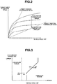
- CVT control unit 12 includes a lockup control part 12b configured to perform a basic control of the lockup clutch control, for enhancement of fuel efficiency while the vehicle is driven with depression of an accelerator, by using a lockup map shown in FIG. 3 .
- lockup control part 12b outputs an LU engagement request to engage the disengaged lockup clutch 3 in response to an event that the operating point defined by vehicle speed VSP and accelerator opening APO crosses an OFF->ON line in FIG. 3 .
- lockup control part 12b outputs an LU disengagement request to disengage the engaged lockup clutch 3 in response to an event that the operating point defined by vehicle speed VSP and accelerator opening APO crosses an ON->OFF line in FIG. 3 .
- CVT control unit 12 includes a meeting point learning control part 12c configured to perform the meeting point learning control.
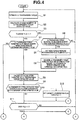
- FIGS. 4 to 7 show a flow of process of meeting point learning control performed by meeting point learning control part 12c of CVT control unit 12 according to the first embodiment (meeting point learning control means).
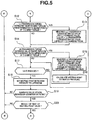
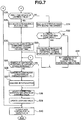
- the following describes steps of the process of meeting point learning control with reference to a flow of meeting point detection (S1 to S20) shown In FIGS. 4 and 5 , a flow of capacity excess detection determination (S21 to S27) shown in FIG. 6 , and a flow of learning value update (S28 to S39) shown in FIG. 7 .
- Engine torque signal value Te is obtained from engine control unit 11 by outputting a request for information.
- Torque capacity coefficient T is given depending on speed ratio, by using characteristics of torque capacity coefficient with respect to speed ratio.
- the term of T ⁇ Ne 2 in equation (1) represents a torque converter transmission torque.
- the meeting point learning control part 12c calculates a quantity of change of the LU transmission torque estimated value, and proceeds to Step S3.
- the monotonous increase determination flag TLUEDGEFLAG is set at Step S5, when the LU transmission torque estimated value change quantity exceeds the edge detection threshold value.
- the meeting point learning control part 12c determines whether or not the LU transmission torque estimated value change quantity > the edge detection threshold value. In case of YES (the LU transmission torque estimated value change quantity > the edge detection threshold value), meeting point learning control part 12c proceeds to Step S5. In case of NO (the LU transmission torque estimated value change quantity ⁇ the edge detection threshold value), meeting point learning control part 12c returns to Step S1.
- the edge detection threshold value is set to a value of the LU transmission torque estimated value change quantity with which it can be determined that the LU transmission torque estimated value has entered a tendency of increase, even with influences of fluctuations of rotational speed, torque, etc. of engine 1, namely, a value slightly above a quantity of change of the LU transmission torque estimated value corresponding to a quantity of such fluctuations.
- Step S6 following the setting of monotonous increase determination flag TLUEDGEFLAG at Step S5, the meeting point learning control part 12c memorizes an LU transmission torque estimated value TLUEDGE and an LU command value LUPRSEDGE when it is determined that the LU transmission torque estimated value change quantity > the edge detection threshold value, and proceeds to Step S8.
- the meeting point learning control part 12c determines whether or not the LU transmission torque estimated value change quantity > a monotonous increase determination threshold value. In case of YES (the LU transmission torque estimated value change quantity > the monotonous increase determination threshold value), meeting point learning control part 12c proceeds to Step S8. In case of NO (the LU transmission torque estimated value change quantity ⁇ the monotonous increase determination threshold value), meeting point learning control part 12c proceeds to Step S40 in the flow of learning value update in FIG. 7 .
- the monotonous increase determination threshold value is set to a value for determining that the LU transmission torque estimated value change quantity is increasing monotonously, namely, a value for excluding situations where the LU transmission torque estimated value shows a small gradient of increase or shows no increase but is unchanged.
- the meeting point learning control part 12c calculates a calculation variation of the LU transmission torque estimated value, and proceeds to Step S9.
- Step S9 following the calculation of the calculation variation of the LU transmission torque estimated value at Step S8, the meeting point learning control part 12c determines whether or not the LU transmission torque estimated value exceeds the calculation variation of the LU transmission torque estimated value. In case of YES (the LU transmission torque estimated value > the calculation variation of the LU transmission torque estimated value), meeting point learning control part 12c proceeds to Step S10. In case of NO (the LU transmission torque estimated value ⁇ the calculation variation of the LU transmission torque estimated value), meeting point learning control part 12c proceeds to Step S11. Step S9 serves as a determination step for confirming the occurrence of LU capacity.
- meeting point learning control part 12c determines that the LU transmission torque estimated value passes through the calculation variation of the LU transmission torque estimated value, based on determination that the LU transmission torque estimated value ⁇ the calculation variation of the LU transmission torque estimated value during the last operation, and the LU transmission torque estimated value > the calculation variation of the LU transmission torque estimated value during the present operation.
- the determination that the LU transmission torque estimated value passes through the calculation variation of the LU transmission torque estimated value serves to confirm detection of the clutch meeting point (point where the LU capacity occurs) within the calculation variation of the LU transmission torque estimated value.
- the meeting point learning control part 12c determines whether or not the LU transmission torque estimated value passes through a predetermined ratio (lower point) of a T/C input torque. In case of YES (the lower point is passed through), meeting point learning control part 12c proceeds to Step S13. In case of NO (the lower point is not passed through), meeting point learning control part 12c proceeds to Step S14.
- the lower point is a point of the LU transmission torque estimated value apart by a predetermined ratio change from the upper point. Both of the upper point and the lower point are less than or equal to 50% of T/C Input torque.
- the meeting point learning control part 12c memorizes an LU transmission torque estimated value TLULOP and an LU command value LUPRSLOP when the lower point is passed through, and proceeds to Step S14.
- the meeting point learning control part 12c determines whether or not the LU transmission torque estimated value passes through a predetermined ratio (upper point) of the T/C input torque. In case of YES (the upper point is passed through), meeting point learning control part 12c proceeds to Step S15. In case of NO (the upper point is not passed through), meeting point learning control part 12c proceeds to Step S17.
- the predetermined ratio of the upper point with respect to T/C input torque is higher than that of the lower point.
- the upper point is a point of the LU transmission torque estimated value apart by the predetermined ratio change from the lower point, and is less than or equal to 50% of T/C input torque.
- Step S15 following the determination at Step S14 that the upper point is passed through, the meeting point learning control part 12c memorizes an LU transmission torque estimated value TLUHIP and an LU command value LUPRSHIP when the upper point is passed through, and proceeds to Step S16.
- the meeting point learning control part 12c calculates a meeting point estimated pressure, and proceeds to Step S17.
- the meeting point learning control part 12c determines whether or not the lockup clutch LU/C is engaged. In case of YES (LU/C is engaged), meeting point learning control part 12c proceeds to Step S18. In case of NO (LU/C is not engaged), meeting point learning control part 12c returns to Step S1.
- the phrase "LU/C is engaged” means that engagement of the lockup clutch LU/C is completed. This determination is affirmed in response to a situation that the LU transmission torque estimated value has reached a predetermined ratio for engagement determination (80% or higher, for example) of the T/C input torque.
- the meeting point learning control part 12c sets a meeting point detection pressure to the LU command value LUPRSEDGE memorized at Step S6, and proceeds to Step S19.
- the meeting point detection pressure is a value of the LU command value corresponding to a detected pressure at the meeting point, which is provisionally set by the present operation.
- the meeting point learning control part 12c determines whether or not a learning value update permission condition is satisfied. In case of YES (the learning value update permission condition is satisfied), meeting point learning control part 12c proceeds to Step S20. In case of NO (the learning value update permission condition is unsatisfied), meeting point learning control part 12c proceeds to Step S40 in the flow of learning value update in FIG. 7 .
- the learning value update permission condition is determined as being satisfied when all of the following requirements are met:
- the meeting point learning control part 12c determines whether or not a result of testing of the meeting point is valid. In case of YES (the result of testing of the meeting point is valid), meeting point learning control part 12c proceeds to Step S28 in the flow of learning value update in FIG. 7 . In case of NO (the result of testing of the meeting point is invalid), meeting point learning control part 12c proceeds to Step S40 in the flow of learning value update in FIG. 7 .
- the testing of the meeting point is implemented by checking an equation of [predetermined lower limit value] ⁇
- the meeting point learning control part 12c determines whether or not the LU transmission torque estimated value calculated by the equation (1) exceeds a capacity excess determination transmission torque threshold value. In case of YES (the LU transmission torque estimated value > the capacity excess determination transmission torque threshold value), meeting point learning control part 12c proceeds to Step S23. In case of NO (the LU transmission torque estimated value ⁇ the capacity excess determination transmission torque threshold value), meeting point learning control part 12c returns to Step S11.
- the meeting point learning control part 12c determines whether or not a capacity excess detection permission condition is satisfied. In case of YES (the capacity excess detection permission condition is satisfied), meeting point learning control part 12c proceeds to Step 524. In case of NO (the capacity excess detection permission condition is unsatisfied), meeting point learning control part 12c returns to Step S11.
- the capacity excess detection permission condition is based on monitoring of changes of engine torque and throttle opening, and is determined as being satisfied when it Is determined that the engine torque is stable and the throttle opening is stable.
- the meeting point learning control part 12c calculates a present number of capacity excess continuous detections by adding 1 to the last number of capacity excess continuous detections, and proceeds to Step S25.
- the meeting point learning control part 12c determines whether or not the number of capacity excess continuous detections is greater than or equal to a threshold value. In case of YES (the number of capacity excess continuous detections ⁇ the threshold value), meeting point learning control part 12c proceeds to Step S26. In case of NO (the number of capacity excess continuous detections ⁇ the threshold value), meeting point learning control part 12c proceeds to Step S27.
- the threshold value for the number of capacity excess continuous detections is set to two or three.
- the meeting point learning control part 12c calculates a learning value correction quantity for state of confirmation of capacity excess, and proceeds to Step S35 in the flow of learning value update in FIG. 7 .
- the learning value correction quantity for state of confirmation of capacity excess is a quantity of correction of the learning value for reducing the learning value to reliably prevent capacity excess, and is set to a value that is several times (five times, for example) the maximum value of the learning value correction quantity for normal state, based on confirmation of capacity excess.
- the meeting point learning control part 12c calculates the learning value correction quantity for state of detection of capacity excess, and proceeds to Step S35 in the flow of learning value update in FIG. 7 .
- the learning value correction quantity for state of detection of capacity excess is a quantity of correction of the learning value for reducing the learning value to prevent capacity excess, and is set to about the maximum value of the learning value correction quantity for normal state, based on detection of capacity excess.
- the meeting point learning control part 12c determines whether or not updating of the learning value of the meeting point is for the first time. In case of YES (first-time update of the learning value), meeting point learning control part 12c proceeds to Step S29. In case of NO (two or more updates of the learning value), meeting point learning control part 12c proceeds to Step S31.
- the meeting point learning control part 12c calculates an initial detection error E_1, and proceeds to Step S30.
- the meeting point learning control part 12c calculates a learning value correction quantity for normal state of learning (for the first time), and proceeds to Step S35.
- the learning value correction quantity for normal state of learning (for the first time) is set to a basic correction pressure f(E_1) with respect to initial detection error E_1, wherein basic correction pressure f(E_1) is equal to about ⁇ 10kPa, for example.
- the meeting point learning control part 12c calculates a detection error E_n for the n-th time, and proceeds to Step S32.
- the meeting point learning control part 12c determines whether or not the present detection error E_n and the last detection error E_n-1 are in the same direction (the same sign). In case of YES (E_n and E_n-1 have the same sign), meeting point learning control part 12c proceeds to Step S33. In case of NO (E_n and E_n-1 have different signs), meeting point learning control part 12c proceeds to Step S34.
- the meeting point learning control part 12c calculates the learning value correction quantity for normal state of learning (for the second time onward), and proceeds to Step S35.
- Step S34 following the determination at Step S32 that E_n and E_n-1 have different signs, the meeting point learning control part 12c sets the learning value correction quantity (for the second time onward) to zero, and proceeds to Step S35.
- the meeting point learning control part 12c determines whether or not the number of capacity excess continuous detections has increased. In case of YES (the number of capacity excess continuous detections has increased), meeting point learning control part 12c proceeds to Step S38. In case of NO (the number of capacity excess continuous detections Is unchanged), meeting point learning control part 12c proceeds to Step S36.
- Step S36 following the determination at Step S35 that the number of capacity excess continuous detections is unchanged, the meeting point learning control part 12c resets the number of capacity excess continuous detections to zero, and proceeds to Step S37.
- the meeting point learning control part 12c selects a correction quantity of the learning value of the meeting point for updating, and proceeds to Step S39.
- the selection of correction quantity of the learning value of the meeting point for updating is implemented by selecting the correction quantity of the learning value for state of detection (confirmation) of capacity excess, when both of the determination of normal learning and the determination of detection (confirmation) of capacity excess are made simultaneously.
- the meeting point learning control part 12c updates the learning value of the meeting point, and proceeds to Step S40.
- the updating of the learning value of the meeting point is implemented by replacing the memorized previously learning value of the meeting point with a new learning value Ln of the meeting point that is obtained by adding the learning value correction quantity to the last learning value L_n-1.
- the meeting point learning control part 12c clears the flags, and proceeds to the end.
- the flags to be cleared are the monotonous increase determination flag TLUEDGEFLAG and the capacity confirmation flag CAPAFLG.
- Step S1 -> Step S2 -> Step S3 -> Step S4 the flow of Step S1 -> Step S2 -> Step S3 -> Step S4 is repeated. During the repetition, the LU transmission torque is estimated at Step S1, and the LU transmission torque estimated value change quantity is calculated at Step S2.
- Step S4 When the LU transmission torque estimated value change quantity thereafter starts to rise and it is determined at Step S4 that the LU transmission torque estimated value change quantity > the edge detection threshold value, the process proceeds as Step S4 -> Step S5 -> Step S6 -> Step S8 -> Step S9 -> Step S11.
- the monotonous increase determination flag TLUEDGEFLAG is set to 1, and at Step S6, it memorizes the LU transmission torque estimated value TLUEDGE and the LU command value LUPRSEDGE when it is determined that the LU transmission torque estimated value change quantity > the edge detection threshold value.
- Step S5 it is determined whether or not the LU transmission torque estimated value change quantity > the monotonous increase determination threshold value, and when the LU transmission torque estimated value change quantity > the monotonous increase determination threshold value, the process proceeds to Step S8, and the meeting point learning process continues.
- Step S23 the process proceeds as Step S23 -> the end, wherein the meeting point learning process Is terminated because the situation is not one where the LU transmission torque estimated value change quantity increases monotonously (the situation is unsuitable for learning using characteristics of monotonous increase of the LU transmission torque estimated value).
- Step S7 While it is determined at Step S7 that the LU transmission torque estimated value change quantity > the monotonous increase determination threshold value, the process proceeds from Step S7 to Step S8 -> Step S9.
- Step S8 the variation of calculation of LU transmission torque estimated value is calculated.
- Step S9 it is determined whether or not the LU transmission torque estimated value has exceeded the variation of calculation of LU transmission torque estimated value.
- the state of (the LU transmission torque estimated value ⁇ the variation of calculation of LU transmission torque estimated value) shifts to the state of (the LU transmission torque estimated value > the variation of calculation of LU transmission torque estimated value) at Step S9, the process proceeds to Step S10.
- Step S12 it is determined whether or not the LU transmission torque estimated value passes through the predetermined ratio (lower point) of the T/C input torque.
- the process proceeds to Step S13 where it memorizes the LU transmission torque estimated value TLULOP and the LU command value LUPRSLOP when the lower point is passed through.
- Step S14 it is determined whether or not the LU transmission torque estimated value passes through the predetermined ratio (upper point) of the T/C input torque.
- the process proceeds to Step S15 where it memorizes the LU transmission torque estimated value TLUHIP and the LU command value LUPRSHIP when the upper point Is passed through.
- the meeting point estimated pressure LUPRSEDGE# is calculated which Is an LU command value at the point where the LU transmission torque estimated value starts to rise on the line passing through the lower point and the upper point.
- the process thereafter proceeds to Step S17 where it is determined whether or not the lockup clutch LU/C is engaged.
- the process proceeds to Step S18 onward.
- the process returns to Step S1.
- the calculation of the LU transmission torque estimated value at Step S1 and the calculation of the LU transmission torque estimated value change quantity at Step S2 are repeated until it is determined that engagement of lockup clutch LU/C is completed.
- Step S17 When it is determined at Step S17 that engagement of lockup clutch LU/C is completed, the process proceeds to Step S18 where the meeting point detection pressure is set to the LU command value LUPRSEDGE memorized at Step S6. Subsequently, at Step S19, it is determined whether or not the learning value update permission condition is satisfied.
- Step S19 When it is determined at Step S19 that the learning value update permission condition is unsatisfied, the process proceeds as Step S40 -> the end, wherein the meeting point learning process is terminated because it is likely to cause erroneous learning of the meeting point learning value.
- Step S20 When it is determined at Step S19 that the learning value update permission condition is satisfied, the process proceeds to Step S20 where it is determined whether or not the result of testing of the meeting point is valid. When it is determined that the result of testing of the meeting point is invalid, the process proceeds as Step S40 -> the end, wherein the meeting point learning process is terminated because it is likely to cause erroneous learning of the meeting point
- Step S11 (Actions of Process of Capacity Excess Detection Determination: FIG. 6 )
- Step S11 the process proceeds from Step S11 to Step S12 onward in FIG. 5 and from Step S11 to Step S21 onward in FIG. 6 , where the process of meeting point detection and the process of capacity excess detection determination are performed in parallel.
- Step S24 the number of capacity excess detections is counted, and if the number of capacity excess detections is already counted, the number of capacity excess detections is incremented by 1 as the number of capacity excess continuous detections.
- Step S25 it is determined whether or not the number of capacity excess continuous detections is greater than or equal to the threshold value (two or three).
- the process proceeds to Step S27 where the learning value correction quantity for state of detection of capacity excess is calculated.
- the learning value correction quantity for state of detection of capacity excess is a quantity of correction of the learning value for reducing the learning value to prevent capacity excess, and is set to about the maximum value of the learning value correction quantity for normal state.
- Step S25 when it is determined at Step S25 whether or not the number of capacity excess continuous detections is greater than or equal to the threshold value, and that the number of capacity excess continuous detections ⁇ the threshold value, the process proceeds to Step S26 where the learning value correction quantity for state of confirmation of capacity excess is calculated.
- the learning value correction quantity for state of confirmation of capacity excess is a quantity of correction of the learning value for reducing the learning value to reliably prevent capacity excess, and is set to a value that is several times (five times, for example) the maximum value of the learning value correction quantity for normal state.
- Step S35 the learning value correction quantity for state of detection (confirmation) of capacity excess is selected as the correction quantity for updating, prior to the learning value correction quantity for normal state of learning.
- Step S39 the learning value is updated.
- Step S19 When it is determined at Step S19 that the learning value update permission condition is satisfied and It is determined at Step S20 that the result of testing of the meeting point is valid, the meeting point is set to the learning detection value. The process then proceeds from Step S20 to Step S28 onward in FIG. 7 where the process of normal learning determination is performed.
- Step S28 it is determined whether or not updating of the learning value of the meeting point is for the first time.
- the process proceeds from Step S28 to Step S29 -> Step S30 -> Step S35 -> Step S36 -> Step S37 -> Step S38 -> Step S39.
- Step S29 the initial detection error E_1 is calculated, and at Step S30, the learning value correction quantity for normal state of learning (for the first time) is calculated. Since the number of capacity excess continuous detections is equal to zero, the process proceeds to Step S37 where the present detection error E_n is memorized in the last detection error E_n-1.
- Step S38 the learning value correction quantity for normal state of learning (for the first time) calculated at Step S30 is selected as a correction quantity of the learning value of the meeting point for updating. Then, at Step S39, the learning value of the meeting point is updated by addition of the learning value correction quantity for normal state of learning (for the first time).
- Step S28 When it is determined at Step S28 that two or more updates of the learning value have been made, and It Is determined that the present detection error E_n and the last detection error E_n-1 are in the same direction, the process proceeds from Step S28 to Step S31 -> Step S32 - > Step S33 -> Step S35 -> Step S36 -> Step S37 -> Step S38 -> Step S39. Following the calculation of the n-th detection error E_n at Step S31 and the determination at Step S32 that E_n and E_n-1 are in the same direction, the learning value correction quantity for normal state of learning (for the second time onward) is calculated at Step S33.
- Step S37 the present detection error E_n is memorized in the last detection error E_n-1.
- Step S38 the learning value correction quantity for normal state of learning (for the second time onward) calculated at Step S33 is selected as a correction quantity of the learning value of the meeting point for updating.
- Step S39 the learning value of the meeting point is updated by addition of the learning value correction quantity for normal state of learning (for the second time onward).
- Step S28 when it is determined at Step S28 that two or more updates of the learning value have been made, and it is determined that the present detection error E_n and the last detection error E_n-1 are in different directions, the process proceeds from Step S28 to Step S31 -> Step S32 -> Step S34 -> Step S35 -> Step S36 -> Step S37 -> Step S38 -> Step S39.
- the learning value correction quantity for normal state of learning Is set to zero (indicating "no correction" at Step S34.
- Step S37 the present detection error E_n is memorized in the last detection error E_n-1.
- Step S38 the value of zero obtained at Step S34 is selected as a correction quantity of the learning value of the meeting point for updating.
- Step S39 the learning value of the meeting point is maintained unchanged from the last learning value.
- a time instant t1 is a time instant at which an LU engagement request is outputted.
- a time instant t2 is a time instant at which the meeting point estimated pressure is calculated.
- a time instant t3 is a time instant at which the meeting point detection pressure is determined.
- a time instant t4 Is a time instant at which the lower point Is passed through.
- a time instant t5 is a time instant at which the upper point is passed through.
- a time instant t6 is a time instant at which 50% of the T/C input torque is passed through.
- a time instant t7 is a time instant at which it is determined that engagement of lockup clutch 3 is completed.
- the LU transmission torque estimated value and the LU transmission torque estimated value change quantity are calculated.
- the LU transmission torque estimated value change quantity exceeds the edge detection threshold value at time instant t3
- the LU command value at time instant t3 is memorized.
- meeting point detection pressure LUPRSEDGE is set to the memorized LU command value.
- the meeting point estimated pressure LUPRSEDGE# is calculated based on the acquired information at the lower point, the acquired information at the upper point, and the LU command value LUPRSEDGE. Namely, as shown in FIG.
- the meeting point estimated pressure LUPRSEDGE# is calculated which is an LU command value at the point (time Instant t2) at which an extension line passing through the lower point and the upper point crosses a coordinate axis indicating that the LU transmission torque estimated value is equal to zero, wherein at the meeting point estimated pressure LUPRSEDGE#, lockup clutch 3 is assumed to shift into a state to transmit the torque.
- the meeting point estimated pressure LUPRSEDGE# is calculated and it is determined that the capacity excess detection permission condition is satisfied, it is determined whether or not the result of testing of the meeting point detection pressure LUPRSEDGE is valid. Namely, as shown in FIG. 8 , when the absolute value of the difference between the meeting point detection pressure LUPRSEDGE and the meeting point estimated pressure LUPRSEDGE# is within the range from the predetermined lower limit value to the predetermined upper limit value, it is determined that the result of testing of the meeting point is valid. When it is determined that the result of testing of the meeting point is valid, the currently acquired meeting point detection pressure LUPRSEDGE is employed in the update process of the learning value, and the meeting point learning value is updated from the last memorized value. When it is determined that the result of testing of the meeting point is invalid, the currently acquired meeting point detection pressure LUPRSEDGE is abandoned and no update of the learning value is performed.
- the standby pressure is an oil pressure to prepare for start of stroke of lockup clutch 3, and charge a lockup hydraulic pressure circuit with working oil, without occurrence of L/U capacity.
- the initial pressure P is an oil pressure produced by an LU command value that is increased in a stepwise manner at start of LU engagement control such that stroke of lockup clutch 3 is completed within a predetermined time period, and is lower than the oil pressure at the meeting point, causing no L/U capacity.
- the learning value L is set within a range from an upper limit to a lower limit possible due to hardware-side variation, and the learning initial value is set to the lower limit of the range of variation.
- the offset pressure is a constant value (conformable value for each accelerator opening) which determines a reduction of the initial pressure P away from the meeting point M.
- the LU command value (LUPRS) to lockup clutch 3 is increased at a predetermined gradient (conformable value).
- the LU command value (LUPRS) at time instant t3 is set to new learning value L_1, and the update operation is performed to update the learning initial value L_0 to new learning value L_1, and new learning value L_1 is thus memorized.
- a time instant t1 is a time instant at which commanding of the last initial pressure P_(n) is issued.
- a time instant t2 is a time instant at which the last learning value L_(n-1) Is reached.
- a time instant t3 is a time instant at which the present learning value L_(n) based on application of correction coefficient g(E_(n-1)) is reached.
- a time instant t4 is a time instant at which the present learning value L_(n) without application of correction coefficient g(E_(n-1)) is reached.
- a time instant t5 is a time instant at which the present learning detected value M_n is reached.
- the LU command value (LUPRS) to lockup clutch 3 is increased at a predetermined gradient (conformable value).
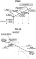
- basic correction pressure f(E_n) is set based on the present detection error E_n, and is limited depending on the magnitude of the present detection error E_n, as shown in FIG. 12 .
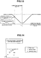
- the correction coefficient g(E_(n-1)) is set based on the last detection error E_n-1 such that correction coefficient g(E_(n-1)) becomes smaller as the absolute value of the last detection error E_n-1 decreases, as shown In FIG. 13 .
- the present learning value L_n is equal to the LU command value (LUPRS) at time instant t3 in FIG. 11 .
- the present learning value L_n is set to the LU command value (LUPRS) at time instant t3, and the last learning value L_(n-1) is updated by the present learning value L_n, and the learning value L_n is thus memorized.
- the present learning value L_n is equal to the LU command value (LUPRS) at time instant t4 in FIG. 11 .
- learning value L_n of the meeting point is updated, and in response to a next LU engagement request for engaging the disengaged lockup clutch 3, the LU command value is increased by one stroke to the next initial pressure P_(n+1). Thereafter, the LU engagement control is performed to Increase the LU command value, which is raised to the next initial pressure P_(n+1), at a gradient with which lockup shocking is suppressed.
- This LU engagement control serves to set a time period from LU engagement request to occurrence of clutch transmission torque to a short constant time period, even with variation in manufacturing and variation in time, ensuring a stable response of engagement of lockup clutch 3.
- the quantity of ⁇ [basic correction pressure f(E_n)] ⁇ [correction coefficient g(E_(n-1))])- is added to the last learning value L_n-1, because the present detection error E_n and the last detection error E_n-1 are in the same direction (same sign).
- the correction quantity of the learning value per one time is limited to the maximum learning value correction quantity (about 10kPa, for example) in the initial stage of the learning, and is set to decrease gradually as the number of learning operations increases.
- the guard function works against a single erroneous detection, as shown in FIG. 16 .
- the meeting point changes up and down (E_n and E_n-1 having different signs) as indicated by 16A, the last learning value is maintained unchanged.
- a point 16F is apparently a meeting point (learning detection value) based on erroneous detection, but is not a basis for the learning, because the sign of this meeting point is different from those of the previous and next meeting points.
- the meeting point (learning detection value) is detected on the same side continuously (E_n and E_n-1 having the same sign) as indicated by 16C, the learning value is corrected based on the present detection error E_n and the last detection error E_n-1.
- a point 16G is apparently a meeting point (learning detection value) based on erroneous detection.
- the present detection error E_n is large but the last detection error E_n-1 is small so that correction coefficient g(E_(n-1)) is set small, whereas the meeting point (learning detection value) changes up and down as indicated by the next situation 16B so that the last learning value is maintained unchanged.
- the learning value is corrected wherein basic correction pressure f(E_n) and correction coefficient g(E_(n-1)) are set small based on the present detection error E_n and the last detection error E_n-1. Accordingly, in a situation where a meeting point (learning detection value) based on erroneous detection appears solely after convergence of the learning value as shown in FIG. 16 , the erroneous detection is prevented from affecting the learning value.
- the guard function does not work against two or more erroneous detections, as shown in FIG. 17 .
- the meeting point (learning detection value) changes up and down (E_n and E_n-1 having different signs) as indicated by 17A, the last learning value is maintained unchanged.
- a point 17F is apparently a meeting point (learning detection value) based on erroneous detection, but is not a basis for the learning, because the sign of this meeting point is different from those of the previous and next meeting points.
- the erroneous detection is not prevented from affecting the learning value. After a shift from a meeting point based on erroneous detection to a meeting point based on normal detection, the learning value converges again toward the true value with preferable response.
- the learning value follows the true value changing slowly as shown in FIG. 18 . While the true value changes slowly from a lower state indicated by 18A to a higher state indicated by 18B, the present detection error E_n and the last detection error E_n-1 are in the same direction (same sign), and the present detection error E_n and the last detection error E_n-1 are small.
- the learning value L_n increases gradually as the number of learning operations increase, wherein the learning value L_n is calculated by addition of ⁇ [basic correction pressure f(E_n)] ⁇ [correction coefficient g(E_(n-1))] ⁇ to the last learning value L_n-1, wherein the basic correction pressure f(E_n) and the correction coefficient g(E_(n-1)) are small. Accordingly, as the true value changes slowly, the learning value follows the true value changing slowly as shown in FIG. 18 .
- the learning value In a situation of stable state after convergence of the learning value (with the true value changing rapidly), the learning value converges quickly and smoothly to the true value changing rapidly as shown in FIG. 19 . While the true value changes rapidly from a lower state indicated by 19A to a higher state indicated by 19B, the learning value is far apart from the true value in an initial stage of the rapid change of the true value. After the rapid change of the true value, the present detection error E_n and the last detection error E_n-1 are in the same direction (same sign), the learning value L_n is calculated by addition of ⁇ [basic correction pressure f(E_n)] ⁇ [correction coefficient g(E_(n-1))] ⁇ to the last learning value L_n-1.
- the correction quantity of the learning value per one time is limited to the maximum learning value correction quantity (about 10kPa, for example), and is set to decrease gradually as the number of learning operations increases. In this way, in a situation where the true value changes rapidly, the learning value converges to the true value quickly by initial learning operations, and as the number of learning operations increases thereafter, the learning value converges to the true value smoothly depending on the present detection error E_n and the last detection error E_n-1, as shown in FIG. 19 .
- a general learning control is known in which when a calculated detection error of a learning detection value is above a predetermined value, a constant learning value correction quantity is added to a last learning value to obtain a present learning value.
- the learning value correction quantity is set to a large constant value, in a situation where the last learning value is close to a true value after convergence and the present detection error is based on an erroneous learning detection value, the present learning value becomes apart from the true value.
- the learning value correction quantity is set to a small constant value, in a situation where the last learning value is apart from the true value, multiple learning experiences are required for convergence of the learning value to the true value.
- the present detection error E_n when the present detection error E_n has the same sign as the last detection error E_n-1, it is configured to: set the correction coefficient g(E_(n-1)) such that the correction coefficient g(E_(n-1)) increases as the absolute value
- the present learning value correction quantity to be added to the last learning value L_n-1 is set to increase as the absolute value
- the learning value correction quantity becomes large so that the present learning value L_n far apart from the true value can be made to converge to the true value quickly.
- This serves to allow the learning value L_n to converge to and be held at the true value, while ensuring the frequency of learning, wherein the learning control is performed based on information about the meeting point at which the lockup clutch 3 starts torque transmission.
- the first embodiment includes the correction coefficient setting part ( FIG. 13 ) configured to set the correction coefficient g(E_(n-1)) such that the correction coefficient g(E_(n-1)) decreases as the absolute value
- the correction coefficient g(E_(n-1)) is set such that the correction coefficient g(E_(n-1)) decreases as the absolute value
- of the last detection error E_n-1 becomes small so that the learning value L_n is thereafter maintained unchanged substantially with slight fluctuations. This serves to enhance the ability of converge of the learning value L_n to the true value in the region where the learning value L_n is apart from the true value, and after converge of the learning value L_n to the true value, suppress change of the learning value L_n.
- the correction coefficient g(E_(n-1)) is set to decrease linearly as the absolute value
- the correction coefficient g(E_(n-1)) may be set to decrease in a curved manner (in a quadratic manner, for example), or may be set to be constant in some range(s), and decrease in a stepwise manner, or may be set by combination of the formers. Namely, the correction coefficient g(E_(n-1)) may be set arbitrarily in consideration of the ability of convergence to the true value and the ability of stabilization at the true value.
- the basic correction pressure f(E_n) as the basic correction quantity I s set to the constant correction pressure less than the present detection error E_n, in the region where the absolute value
- the learning control is configured to set the learning value correction quantity constant when the absolute value
- the feature of correcting the learning value L_n with the variable correction value serves to enhance the ability of converge of the learning value L_n to the true value and thereby obtain the learning value L_n within a reduced gap from the true value.
- the present detection error E_n when the present detection error E_n is different in sign from a last detection error E_n-1, the present learning value correction quantity is set to zero, and the present learning value L_n is set unchanged from the last learning value L_n-1. Namely, with the true value constant, the learning control causes the learning value to approach the true value gradually from one side.
- the condition that the present detection error E_n is different in sign from a last detection error E_n-1 means that it is likely that the learning detected values M_n, M_n-1, which are used to calculate the detection errors E_n, E_n-1, respectively, are based on erroneous detection.
- the feature of maintaining the last learning value L_n-1 unchanged, when the present detection error E_n is different in sign from the last detection error E_n-1 serves to exclude erroneous detection of the learning detected values M_n, M_n-1 and thereby ensure the stability of the learning value L_n.
- the LU transmission torque is estimated based on the difference between the engine torque (engine torque signal value Te) and the torque converter transmission torque (T ⁇ N 2 ).
- the meeting point detection pressure LUPRSEDGE when it is determined that the lockup transmission torque estimated value enters a tendency of increase, is used as meeting point information for the meeting point learning control. While the vehicle is running, change of the engine rotational speed causes a change of the transmission torque of torque converter 4, and a change of the transmission torque of lockup clutch 3.
- the meeting point detection pressure LUPRSEDGE is an oil pressure at which the lockup transmission torque estimated value enters a tendency of increase and which is estimated based on the difference between the engine torque (engine torque signal value Te) and the torque converter transmission torque (T ⁇ N 2 ); namely, the meeting point detection pressure LUPRSEDGE is an oil pressure with which the transmission torque of lockup clutch 3 is in a state maintained from decreasing.
- the feature that learning value L_n is determined based on the meeting point information that is the meeting point detection pressure LUPRSEDGE when it is determined that the lockup transmission torque estimated value enters a tendency of increase, serves to prevent erroneous detection.
- lockup clutch 3 undergoes the lockup engagement control for transition from disengaged state into engaged state while the vehicle is running, the process of meeting point learning control is started. This serves to prevent erroneous learning while ensuring the frequency of learning, when performing the learning control based on the information of the meeting point at which lockup clutch 3 starts torque transmission.
- the lockup clutch control device and lockup clutch control method applied to the engine vehicle according to the embodiment produces the following listed effects.
- meeting point learning control part 12c is configured to perform the learning control to obtain the learning value L_n of the meeting point of the LU command value, wherein meeting point detection pressure LUPRSEDGE is information about the meeting point at which lockup clutch 3 starts torque transmission.
- meeting point learning control part 12c may be configured to perform a learning control to obtain a learning value of an initial pressure of the LU command value, wherein meeting point detection pressure LUPRSEDGE is information about the meeting point.
- the learning control may be configured to obtain a learning value of the gradient of the LU command value.
- the learning control may be configured to obtain a learning value of an initial pressure and a learning value of the gradient of the LU command value.
- meeting point learning control part 12c is configured to obtain the learning value L based on meeting point detection pressure LUPRSEDGE, when it is determined that the result of testing based on meeting point estimated pressure LUPRSEDGE# is valid.
- meeting point learning control part 12c may be configured to perform testing based on a condition other than meeting point estimated pressure, such as a difference from the memorized meeting point learning value, and when it is determined that the result of testing is valid, obtain a learning value based on meeting point detection pressure.
- meeting point learning control part 12c may be configured to obtain a learning value based on meeting point detection pressure in response to a satisfaction of the learning value update permission condition, wherein the learning value update permission condition is set strict to omit the testing.
- meeting point learning control part 12c is configured to set the basic correction pressure f(E_n) and the correction coefficient g(E_(n-1)) to variable values, respectively.
- meeting point learning control part 12c may be configured to set the basic correction pressure f(E_n) to a constant value, and set the correction coefficient g(E_(n-1)) to a variable value.
- meeting point learning control part 12c may be configured to vary the learning value correction quantity in a stepwise manner depending on the magnitude of the last detection error E_n-1.
- the first embodiment has the exemplified configuration that the lockup clutch control device and lockup clutch control method according to the present invention are applied to the engine vehicle where the continuously variable transmission is mounted.
- the lockup clutch control device and lockup clutch control method according to the present invention may be applied to a vehicle such as a hybrid vehicle where an engine is mounted as a drive source, wherein the transmission may be a step-shift automatic transmission configured to automatically perform step-shifting.
- the present invention may be applied to a vehicle where a torque converter is mounted between an engine and a transmission, wherein the torque converter includes a lockup clutch.
Landscapes
- Engineering & Computer Science (AREA)
- General Engineering & Computer Science (AREA)
- Mechanical Engineering (AREA)
- Physics & Mathematics (AREA)
- Fluid Mechanics (AREA)
- Control Of Transmission Device (AREA)
- Hydraulic Clutches, Magnetic Clutches, Fluid Clutches, And Fluid Joints (AREA)
- Control Of Fluid Gearings (AREA)
Applications Claiming Priority (2)
| Application Number | Priority Date | Filing Date | Title |
|---|---|---|---|
| JP2015180175 | 2015-09-11 | ||
| PCT/JP2016/075395 WO2017043381A1 (fr) | 2015-09-11 | 2016-08-31 | Dispositif et procédé de commande d'embrayage de verrouillage pour véhicule |
Publications (2)
| Publication Number | Publication Date |
|---|---|
| EP3348879A1 true EP3348879A1 (fr) | 2018-07-18 |
| EP3348879A4 EP3348879A4 (fr) | 2018-09-19 |
Family
ID=58239736
Family Applications (1)
| Application Number | Title | Priority Date | Filing Date |
|---|---|---|---|
| EP16844242.4A Withdrawn EP3348879A4 (fr) | 2015-09-11 | 2016-08-31 | Dispositif et procédé de commande d'embrayage de verrouillage pour véhicule |
Country Status (6)
| Country | Link |
|---|---|
| US (1) | US10480648B2 (fr) |
| EP (1) | EP3348879A4 (fr) |
| JP (1) | JP6437124B2 (fr) |
| KR (1) | KR102000892B1 (fr) |
| CN (1) | CN107949732B (fr) |
| WO (1) | WO2017043381A1 (fr) |
Families Citing this family (4)
| Publication number | Priority date | Publication date | Assignee | Title |
|---|---|---|---|---|
| JP6782657B2 (ja) * | 2017-03-29 | 2020-11-11 | 本田技研工業株式会社 | クラッチ制御装置 |
| KR102404301B1 (ko) * | 2017-07-21 | 2022-06-07 | 생-고뱅 퍼포먼스 플라스틱스 코포레이션 | 3차원 바디를 형성하는 방법 |
| KR20200113527A (ko) | 2019-03-25 | 2020-10-07 | 현대자동차주식회사 | 차량의 변속기 클러치토크 오학습 방지방법 |
| CN111089166B (zh) * | 2020-03-23 | 2020-07-10 | 盛瑞传动股份有限公司 | 液力变矩器的自学习方法及装置、电子设备及存储介质 |
Family Cites Families (17)
| Publication number | Priority date | Publication date | Assignee | Title |
|---|---|---|---|---|
| US5335174A (en) * | 1990-04-04 | 1994-08-02 | Zexel Corporation | Correcting method for data used for control operation of vehicular clutch |
| JP3191632B2 (ja) * | 1995-08-09 | 2001-07-23 | トヨタ自動車株式会社 | 車両用直結クラッチのスリップ制御装置 |
| JP4496603B2 (ja) * | 2000-05-22 | 2010-07-07 | トヨタ自動車株式会社 | 車両用クラッチの制御装置 |
| JP2002295529A (ja) * | 2001-03-28 | 2002-10-09 | Isuzu Motors Ltd | クラッチのトルク点学習方法 |
| JP2004183704A (ja) * | 2002-11-29 | 2004-07-02 | Toyota Motor Corp | 無段変速機構を含む駆動系統の制御装置 |
| JP4178994B2 (ja) * | 2003-02-25 | 2008-11-12 | トヨタ自動車株式会社 | 車両用動力伝達装置の制御装置 |
| JP2005291174A (ja) * | 2004-04-05 | 2005-10-20 | Denso Corp | 車両用エンジンのトルク制御装置 |
| JP4779452B2 (ja) * | 2005-06-01 | 2011-09-28 | トヨタ自動車株式会社 | 車両の制御装置 |
| JP4182972B2 (ja) * | 2005-10-17 | 2008-11-19 | トヨタ自動車株式会社 | 無段変速機構を含む駆動系統の制御装置 |
| JP4899457B2 (ja) * | 2005-12-13 | 2012-03-21 | トヨタ自動車株式会社 | 車両用動力伝達装置の制御装置 |
| JP5203401B2 (ja) * | 2010-02-05 | 2013-06-05 | 本田技研工業株式会社 | ツインクラッチ式変速機 |
| JP5031052B2 (ja) * | 2010-03-16 | 2012-09-19 | ジヤトコ株式会社 | 自動変速機の制御装置 |
| US8548699B2 (en) * | 2010-05-25 | 2013-10-01 | GM Global Technology Operations LLC | Control system and method for adaptive control of transmission fluid operating pressures |
| JP2012021549A (ja) * | 2010-07-12 | 2012-02-02 | Honda Motor Co Ltd | 自動変速機のロックアップクラッチ制御装置 |
| JP5839396B2 (ja) * | 2011-12-27 | 2016-01-06 | ダイハツ工業株式会社 | ロックアップクラッチ制御装置 |
| JP6187058B2 (ja) * | 2013-09-09 | 2017-08-30 | 日産自動車株式会社 | ハイブリッド車両の制御装置 |
| JP6187057B2 (ja) * | 2013-09-09 | 2017-08-30 | 日産自動車株式会社 | ハイブリッド車両の制御装置 |
-
2016
- 2016-08-31 KR KR1020187006137A patent/KR102000892B1/ko active IP Right Grant
- 2016-08-31 WO PCT/JP2016/075395 patent/WO2017043381A1/fr active Application Filing
- 2016-08-31 EP EP16844242.4A patent/EP3348879A4/fr not_active Withdrawn
- 2016-08-31 US US15/757,455 patent/US10480648B2/en active Active
- 2016-08-31 CN CN201680051749.6A patent/CN107949732B/zh active Active
- 2016-08-31 JP JP2017539132A patent/JP6437124B2/ja active Active
Also Published As
| Publication number | Publication date |
|---|---|
| WO2017043381A1 (fr) | 2017-03-16 |
| US10480648B2 (en) | 2019-11-19 |
| CN107949732B (zh) | 2019-09-27 |
| EP3348879A4 (fr) | 2018-09-19 |
| JP6437124B2 (ja) | 2018-12-12 |
| US20180245689A1 (en) | 2018-08-30 |
| CN107949732A (zh) | 2018-04-20 |
| JPWO2017043381A1 (ja) | 2018-06-07 |
| KR102000892B1 (ko) | 2019-07-16 |
| KR20180037231A (ko) | 2018-04-11 |
Similar Documents
| Publication | Publication Date | Title |
|---|---|---|
| EP3348878A1 (fr) | Dispositif de commande d'embrayage de verrouillage pour véhicule, et procédé de commande d'embrayage de verrouillage | |
| EP3348879A1 (fr) | Dispositif et procédé de commande d'embrayage de verrouillage pour véhicule | |
| EP2426378B1 (fr) | Dispositif de commande de transmission à variation continue basé sur une courroie, et procédé de commande afférent | |
| EP2426379B1 (fr) | Dispositif de commande de transmission à variation continue basé sur une courroie, et procédé de commande afférent | |
| US9696333B2 (en) | Display control apparatus for meter | |
| US9897625B2 (en) | Display control apparatus for meter | |
| EP3190316B1 (fr) | Dispositif de commande d'embrayage de verrouillage pour vehicule | |
| EP2075491A2 (fr) | Dispositif de commande d'embrayage de pontage pour transmission automatique et procédé de commande correspondant | |
| EP1531288A2 (fr) | Transmission de puissance avec convertisseur de couple hydrodynamique muni de moyens de pontage et procédé de commande de pontage | |
| US10053003B2 (en) | Display control device for meter | |
| US10175143B2 (en) | Display of a meter during an upshift | |
| EP2754925B1 (fr) | Dispositif de commande pour transmission à variation continue | |
| EP3343075A1 (fr) | Dispositif de commande d'embrayage de verrouillage de véhicule et procédé de commande d'embrayage de verrouillage | |
| CN110789525B (zh) | 驱动力控制装置 | |
| US10175144B2 (en) | Rotational engine speed display device | |
| EP3345802B1 (fr) | Dispositif de contrôle pour véhicule | |
| US10518641B2 (en) | Control apparatus for vehicle | |
| JP2008267609A (ja) | 車両の発進制御装置 |
Legal Events
| Date | Code | Title | Description |
|---|---|---|---|
| PUAI | Public reference made under article 153(3) epc to a published international application that has entered the european phase |
Free format text: ORIGINAL CODE: 0009012 |
|
| 17P | Request for examination filed |
Effective date: 20180302 |
|
| AK | Designated contracting states |
Kind code of ref document: A1 Designated state(s): AL AT BE BG CH CY CZ DE DK EE ES FI FR GB GR HR HU IE IS IT LI LT LU LV MC MK MT NL NO PL PT RO RS SE SI SK SM TR |
|
| AX | Request for extension of the european patent |
Extension state: BA ME |
|
| A4 | Supplementary search report drawn up and despatched |
Effective date: 20180820 |
|
| RIC1 | Information provided on ipc code assigned before grant |
Ipc: F16H 61/14 20060101AFI20180813BHEP |
|
| DAV | Request for validation of the european patent (deleted) | ||
| DAX | Request for extension of the european patent (deleted) | ||
| GRAP | Despatch of communication of intention to grant a patent |
Free format text: ORIGINAL CODE: EPIDOSNIGR1 |
|
| STAA | Information on the status of an ep patent application or granted ep patent |
Free format text: STATUS: THE APPLICATION HAS BEEN WITHDRAWN |
|
| INTG | Intention to grant announced |
Effective date: 20190222 |
|
| 18W | Application withdrawn |
Effective date: 20190220 |