EP3345857B1 - Verfahren und system zum steuern des krans einer arbeitsmaschine durch verwendung einer auslegerspitzensteuerung - Google Patents
Verfahren und system zum steuern des krans einer arbeitsmaschine durch verwendung einer auslegerspitzensteuerung Download PDFInfo
- Publication number
- EP3345857B1 EP3345857B1 EP18152966.0A EP18152966A EP3345857B1 EP 3345857 B1 EP3345857 B1 EP 3345857B1 EP 18152966 A EP18152966 A EP 18152966A EP 3345857 B1 EP3345857 B1 EP 3345857B1
- Authority
- EP
- European Patent Office
- Prior art keywords
- crane
- boom
- control
- head
- working machine
- Prior art date
- Legal status (The legal status is an assumption and is not a legal conclusion. Google has not performed a legal analysis and makes no representation as to the accuracy of the status listed.)
- Active
Links
- 238000000034 method Methods 0.000 title claims description 35
- 238000012545 processing Methods 0.000 claims description 11
- 230000000670 limiting effect Effects 0.000 claims description 4
- 238000004364 calculation method Methods 0.000 description 3
- 241001124569 Lycaenidae Species 0.000 description 1
- 238000013459 approach Methods 0.000 description 1
- 238000004891 communication Methods 0.000 description 1
- 230000001010 compromised effect Effects 0.000 description 1
- 238000005094 computer simulation Methods 0.000 description 1
- 230000003247 decreasing effect Effects 0.000 description 1
- 230000001419 dependent effect Effects 0.000 description 1
- 238000005265 energy consumption Methods 0.000 description 1
- 230000002452 interceptive effect Effects 0.000 description 1
- 238000012913 prioritisation Methods 0.000 description 1
- 230000002829 reductive effect Effects 0.000 description 1
- 238000011160 research Methods 0.000 description 1
- 230000011218 segmentation Effects 0.000 description 1
- 230000007704 transition Effects 0.000 description 1
Images
Classifications
-
- B—PERFORMING OPERATIONS; TRANSPORTING
- B66—HOISTING; LIFTING; HAULING
- B66C—CRANES; LOAD-ENGAGING ELEMENTS OR DEVICES FOR CRANES, CAPSTANS, WINCHES, OR TACKLES
- B66C13/00—Other constructional features or details
- B66C13/18—Control systems or devices
-
- A—HUMAN NECESSITIES
- A01—AGRICULTURE; FORESTRY; ANIMAL HUSBANDRY; HUNTING; TRAPPING; FISHING
- A01G—HORTICULTURE; CULTIVATION OF VEGETABLES, FLOWERS, RICE, FRUIT, VINES, HOPS OR SEAWEED; FORESTRY; WATERING
- A01G23/00—Forestry
-
- A—HUMAN NECESSITIES
- A01—AGRICULTURE; FORESTRY; ANIMAL HUSBANDRY; HUNTING; TRAPPING; FISHING
- A01G—HORTICULTURE; CULTIVATION OF VEGETABLES, FLOWERS, RICE, FRUIT, VINES, HOPS OR SEAWEED; FORESTRY; WATERING
- A01G23/00—Forestry
- A01G23/003—Collecting felled trees
-
- B—PERFORMING OPERATIONS; TRANSPORTING
- B66—HOISTING; LIFTING; HAULING
- B66C—CRANES; LOAD-ENGAGING ELEMENTS OR DEVICES FOR CRANES, CAPSTANS, WINCHES, OR TACKLES
- B66C23/00—Cranes comprising essentially a beam, boom, or triangular structure acting as a cantilever and mounted for translatory of swinging movements in vertical or horizontal planes or a combination of such movements, e.g. jib-cranes, derricks, tower cranes
- B66C23/18—Cranes comprising essentially a beam, boom, or triangular structure acting as a cantilever and mounted for translatory of swinging movements in vertical or horizontal planes or a combination of such movements, e.g. jib-cranes, derricks, tower cranes specially adapted for use in particular purposes
- B66C23/36—Cranes comprising essentially a beam, boom, or triangular structure acting as a cantilever and mounted for translatory of swinging movements in vertical or horizontal planes or a combination of such movements, e.g. jib-cranes, derricks, tower cranes specially adapted for use in particular purposes mounted on road or rail vehicles; Manually-movable jib-cranes for use in workshops; Floating cranes
- B66C23/42—Cranes comprising essentially a beam, boom, or triangular structure acting as a cantilever and mounted for translatory of swinging movements in vertical or horizontal planes or a combination of such movements, e.g. jib-cranes, derricks, tower cranes specially adapted for use in particular purposes mounted on road or rail vehicles; Manually-movable jib-cranes for use in workshops; Floating cranes with jibs of adjustable configuration, e.g. foldable
-
- E—FIXED CONSTRUCTIONS
- E02—HYDRAULIC ENGINEERING; FOUNDATIONS; SOIL SHIFTING
- E02F—DREDGING; SOIL-SHIFTING
- E02F3/00—Dredgers; Soil-shifting machines
- E02F3/04—Dredgers; Soil-shifting machines mechanically-driven
- E02F3/28—Dredgers; Soil-shifting machines mechanically-driven with digging tools mounted on a dipper- or bucket-arm, i.e. there is either one arm or a pair of arms, e.g. dippers, buckets
- E02F3/36—Component parts
- E02F3/42—Drives for dippers, buckets, dipper-arms or bucket-arms
- E02F3/43—Control of dipper or bucket position; Control of sequence of drive operations
- E02F3/435—Control of dipper or bucket position; Control of sequence of drive operations for dipper-arms, backhoes or the like
- E02F3/437—Control of dipper or bucket position; Control of sequence of drive operations for dipper-arms, backhoes or the like providing automatic sequences of movements, e.g. linear excavation, keeping dipper angle constant
-
- E—FIXED CONSTRUCTIONS
- E02—HYDRAULIC ENGINEERING; FOUNDATIONS; SOIL SHIFTING
- E02F—DREDGING; SOIL-SHIFTING
- E02F9/00—Component parts of dredgers or soil-shifting machines, not restricted to one of the kinds covered by groups E02F3/00 - E02F7/00
- E02F9/20—Drives; Control devices
- E02F9/2025—Particular purposes of control systems not otherwise provided for
- E02F9/2033—Limiting the movement of frames or implements, e.g. to avoid collision between implements and the cabin
-
- E—FIXED CONSTRUCTIONS
- E02—HYDRAULIC ENGINEERING; FOUNDATIONS; SOIL SHIFTING
- E02F—DREDGING; SOIL-SHIFTING
- E02F9/00—Component parts of dredgers or soil-shifting machines, not restricted to one of the kinds covered by groups E02F3/00 - E02F7/00
- E02F9/20—Drives; Control devices
- E02F9/22—Hydraulic or pneumatic drives
- E02F9/2203—Arrangements for controlling the attitude of actuators, e.g. speed, floating function
- E02F9/2214—Arrangements for controlling the attitude of actuators, e.g. speed, floating function for reducing the shock generated at the stroke end
Definitions
- the invention relates to a method for controlling the crane of a working machine by using boom tip control.
- the invention also relates to a system for controlling the crane, or crane, of a working machine according to the method of the invention.
- a crane mounted on a working machine is in most cases still controlled in by controlling the actuator provided in connection with each boom of the crane separately.
- the driver has to combine the movements of various actuators in order to make the crane move in a desired way.
- cranes are used for moving an implement fastened to the head of the crane.
- the implement is a harvester head or a loading grapple, depending on whether the machine is a harvester or a forwarder.
- the crane is normally moved from the load space of the forwarder to the side of a log pile and back to the load space.
- the crane When a harvester is used for felling of timber, the crane is normally moved in the horizontal direction from the working machine towards the trees to be felled and, after the felling, in a suitable direction where a pile of cut and delimbed tree trunks is placed.
- the aim of the movements of the crane is to move the implement at the head of the crane from one place to another. This may be the reason why a method has been recently developed for controlling the crane in a way that serves this aim better and thereby facilitates the work of the driver of the machine.
- boom tip control or coordinated control
- the driver controls the crane in such a way that the control devices of the working machine are used for directly controlling the movement of the head of the crane in different directions of motion.
- a single control function of the control device is used for controlling the head of the crane to move e.g. in the horizontal direction away from the working machine and back towards the working machine, another control function is used for controlling the movement upwards and downwards in the vertical direction, and a third control function is used for controlling the turning of the whole crane to the left and to the right in the horizontal direction.
- this so-called boom tip control is motorically less demanding, because when it is applied, the driver does not need to control the different actuators separately and to know how to combine the relationship between the movements of the single booms generated by them with the movements of the head of the crane, but this is performed automatically by the control system of the working machine according to the direction of motion where the driver wants the head of the crane to move.
- boom tip control has been found to make the work easier and more efficient, particularly for a driver with little experience.
- Such a method and apparatus for controlling the crane on the basis of boom tip control is described in the thesis by Markus Saarela, "Coordinated Motion Control of a Log Loader Boom".
- the crane comprises two to three booms connected to each other and to the working machine in an articulated or otherwise movable manner.
- the forest machines manufactured by the applicant typically comprise a hoisting boom connected at its first end in an articulated manner to a traverser mounted on the body of the working machine in a swivelled manner with respect to the vertical axis, a stick boom connected at its first end in an articulated manner to the second end of the hoisting boom, as well as an extension boom movable linearly out of the second end of the stick boom, in the longitudinal direction of the stick boom, and back into the stick boom.
- the control system has, in principle, an infinite number of alternatives selectable for implementing a movement in a given direction of motion.
- some of these alternatives are always such that their implementation will lead to a situation in which the movement of the crane is more difficult than the implementation of another alternative, because of one or more factors limiting the movement of the booms of the crane.
- This may mean, for example, that in a certain position the head of the crane will not move at all if an attempt is made to steer it in a direction whose implementation brings the control system to a situation in which it would have to move an actuator although this is, for example, in its extreme position, or in which a boom would hit the working machine, the ground, or another surrounding obstacle.
- the driver has to move the crane first in a suitable direction, in which the boom tip control can move the crane, to be able to continue the work.
- the aim of the invention is achieved by a method and a system, in which the control system in a working machine, controlling the movements of the head of the crane of the working machine, is programmed to operate in such a way that it selects the speeds of motion of the different booms of the crane on the basis of predetermined factors in such a way that the desired direction and speed of motion of the head of the crane is implemented by using speeds of motion of the different booms of the crane which are suitable for the situation.
- the method and the system according to the invention have the advantage that when using boom tip control according to the invention, it is faster and easier to control the crane of the working machine, because the movement of the head of the crane is not prevented or complicated even if a boom of the crane is in the extreme end of its range of motion, or if a boom is in a position from which it cannot move further in a direction required for the movement of the head of the crane in the desired direction because of an obstacle or for another reason, or if the head of the crane is moving in a direction which would lead to e.g. a risk of collision. Thanks to this, the driver does not need to make extra movements manually in order to avoid these situations, whereby the operation of the crane becomes easier and faster with respect to the boom tip control implemented in the way of prior art.
- the speed of motion of at least one other boom is increased.
- the working machine is a forest machine equipped with a load space
- the crane comprises a hoisting boom connected at its first end in an articulated manner to the working machine, a stick boom connected at its first end in an articulated manner to the second end of the hoisting boom, and an extension boom connected to the stick boom at its second end and movable linearly outwards and inwards in the longitudinal direction of the stick boom.
- the speed of motion of the extension boom is limited when the head of the crane is within the load space.
- the speed of motion of the extension boom is limited when the head of the crane is at a predetermined distance from the load space.
- the boom tip control is switched off in one or some of the following ways when the head of the crane is within a given area or reaches a given area by its movement: automatically, by a control function to be generated by a separate control device, or by maintaining a control function for controlling another function for a predetermined time.
- the boom tip control is automatically switched on again when the head of the crane moves out of a given area.
- control system of the working machine comprises a data processing unit for controlling the movements of the crane by programmable software in the data processing unit, and the control element is software stored in the data processing unit.
- the method and the system according to the invention can be applied in a variety of working machines equipped with a crane, for example in various excavators and forest machines.
- the method can be well utilized in, for example, forwarders 10 such as that shown in Fig. 1 , and harvesters 44 such as that shown in Fig. 3 .
- the actuators used for moving different booms of a crane in a working machine are hydraulic cylinders, but in principle they could also be other actuators with linear movements, such as pneumatic cylinders or spindle motors.
- actuators generating a rotary motion such as hydraulic or electric motors.
- control system equipped with a programmable data processing unit and controlling the movements of the crane by means of control functions generated by control devices placed in the cabin of the working machine in such a way that that the control system converts a given control function into a control command for generating a desired movement of one or some actuators in the working machine.
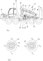
- the forest machine shown in Fig. 1 is a forwarder 10 intended for hauling felled tree trunks out of the forest.
- the rear part of the body 12 of the forwarder 10 is provided with a load space 14 formed for the transportation of the tree trunks in a space between bunks 16.
- the front part of the forwarder 10 is provided with a driving motor 18 and a cabin 20, with its steering and control equipment.
- the control levers for the left and the right hand, shown in Fig. 2 are provided within the cabin.
- the crane 22 intended for the manipulation of tree trunks is provided between the cabin 20 and the load space 14.
- the crane 22 consists of a hoisting boom 24, a stick boom 26, and an extension boom 28.
- the crane 22 is mounted on the body 12 of the forwarder by means of a traverser 30 that is rotatable about a vertical axis with respect to the same in such a way that it can be rotated about the forwarder 10, from the left to the right and vice versa in lateral direction with respect to the body 12.
- the hoisting boom 24 is connected at its first end in an articulated manner to the traverser, to be turnable with respect to a horizontal axis.
- the stick boom 26 is connected in an articulated manner to the second end of the hoisting boom 24, and the extension boom 28 is arranged at the end of the stick boom to be movable in its longitudinal direction in such a way that it is movable from the end of the stick boom by its range of motion out of the end of the stick boom and back into the stick boom 26.
- actuators 32, 34 and 36 are provided which operate in a way known as such, for example hydraulically, and by which the hoisting boom 24 can be turned with respect to the traverser 30, the stick boom 36 can be turned with respect to the hoisting boom 24, and the extension boom 28 can be moved outwards from the stick boom 22 and back inwards.
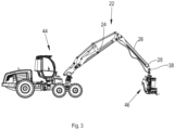
- a loading grapple 40 is provided, equipped with gripping members 48 known as such, which are turned towards or away from each other by an actuator provided in them, wherein the loading grapple 40 can be used for gripping one or more tree trunks for hauling them to a desired location.
- the loading grapple 40 can also be rotated by a rotating device 42 provided therein, so that the trunks in the loading grapple 40 can be brought to a suitable position when they are e.g. loaded into or unloaded from the loading space 14.
- the control of the forwarder 10, the crane 22 and the loading grapple 40 is configured to be performed from the cabin 30 placed in the front part of the body 12.
- the cabin 30 is provided with various control devices known as such, for example the control lever 50 for the left hand and the control lever 52 for the right hand as shown in Fig. 2 , as well as rocker levers 54 and 56 provided in these for controlling e.g. the movement of the crane 22 and the opening and closing of the gripping members of the loading grapple 40 with control functions generated by these controls.
- control commands generated by the control functions given with the control lever 50 for the left hand and the control lever 52 for the right hand are transferred from these controls by communication buses to a data processing unit located in the control system and actually taking care of the control of the actuators 32, 34 and 36 for generating the functions of the crane 22 as well as the actuator controlling the opening of the loading grapple, and the rotating device 42, by means of electro-hydraulic control valves in their hydraulic circuits.
- FIG 3 shows a harvester 44 equipped with a corresponding crane.
- the control of the crane 22 is implemented in a similar way but for the control of the harvester unit 46, more control functions have to be generated by various control devices. Some of these may be implemented by means of control devices separate from the control lever 50 for the left hand and the control lever 52 for the right hand shown in Fig. 2 . However, these do not need to be presented in more detail in this context, because the subject of interest is merely the control of the crane 22 which is implemented in the same way in the forest machines shown in Figs. 1 and 3 .
- Boom tip control is applied for controlling the crane 22 in the forwarder 10 according to Fig. 1 and in the harvester 44 according to Fig. 3 . Consequently, when the crane 22 is controlled with control devices in the cabin, particularly the control lever 50 for the left hand and the control lever 52 for the right hand can be applied for determining the desired direction of motion of the head 38 of the crane.
- software has been programmed in the data processing unit of the control system to calculate the speeds of motion needed for the actuators 32, 34 and 36 moving the different booms, by applying kinematic equations in such a way that the desired direction and speed of motion of the head 38 of the crane are achieved as well as possible.
- the factors (i.e . criteria) applied are implemented in the boom tip control of the crane 22 in the forwarder 10 of Fig. 1 and in the harvester of Fig. 3 in such a way that when a given criterion is met, the desired direction of motion of the head 38 of the crane, or the way of putting it into action (i.e . the booms by which the movement is implemented) is changed according to the criteria.
- the automatic correcting functions modify the control command for controlling a given boom or given booms 24, 26, 28 of the crane 22, and/or the way in which the speeds of motion of the single booms, obtained as a result of calculation, are determined for the different booms. This is performed by software in the data processing unit of the control system of the working machine on the basis of the location of the head 38 of the crane and the positions of the different booms 24, 26, 28 of the crane 22 with respect to each other.
- control of the crane 22 by boom tip control is executed with control devices 50 and 52 of Fig. 2 , in a normal situation in the following way (that is, when the control system does not modify the control commands to be generated with the different control functions):
- the control lever 50 for the left hand is turned in the direction +Yv
- the head 38 of the crane will move away from the working machine in the horizontal direction.
- the control lever 50 for the left hand is turned in the direction Yv
- the head 38 of the crane will move towards the working machine in the horizontal direction.
- the driver of the working machine will turn the left control lever obliquely to the left and forward (that is, in a direction between the directions +Yv and +Xv).
- the speed of the movement of the head 38 of the crane is directly proportional to how much the control lever is turned in the direction of the control function for generating said movement.
- the crane controlled according to a method not forming part of the invention will move precisely in the way controlled by the driver only if there is no obstacle for moving the head of the crane in said direction of motion controlled by the driver.
- the segmentation of the movement of the head of the crane among the single booms is automatically adjusted on the basis of certain factors (criteria) depending on the position and location of the crane 22.
- any movement of a boom of the crane 22 approaches its end limit (which is typically caused by the limitedness of the range of motion of the actuator for moving the same), its speed is started to reduce well in advance (at a given distance from the end limit of said movement). This distance will depend on the structure of the crane and the lengths of the booms. Furthermore, the deceleration may take place gradually in a ramp-like manner. When the speed of one boom is decreased, the speed of motion of the other boom is increased respectively so that the direction and speed of motion of the head of the crane, desired by the driver, are achieved. The increase in the speed of the other booms / one other boom may take place in a ramp-like manner similar to the deceleration of the boom approaching its end limit. This feature is effective for all booms of the crane 22, that is, the hoisting boom 24, the stick boom 26 and the extension boom 28.
- a more precise example is a situation, in which a loading grapple 50 is brought from a long distance closer to the machine.
- all the booms are in use, that is, the hoisting boom 24, the stick boom 26 and the extension boom 28.
- the extension boom 28 comes close to its end limit, to a certain limit distance from it, its movement is gradually decelerated.
- the speeds of the hoisting boom 24 and the stick boom 26 are increased correspondingly.
- the extension boom 28 has been totally withdrawn into the stick boom 26, the movement is continued merely with the hoisting boom 24 and the stick boom 26.
- the desired speed of motion of the head 38 of the crane can be achieved by a large variety of speed combinations of different booms.
- Factors on the selection of the weightings may include, for example, the maximum speed of motion of the head 38 of the crane, the smooth application of the boom, the relative strengths of the actuators 32, 34 and 36, and the need to keep the crane 22 in an advantageous position for the next movements.
- the software programmed in the control system comprises basic rules which apply in very different situations.
- prioritizations of the movements of different booms i.e . different actuators
- the movements of different booms include the following:
- a direction of motion is to be sought for the head 38 of the crane, which direction does not deviate too much from the desired direction of motion and which will result in the crane 22 circumventing the obstacle to the movement.
- This is implemented so that when deviating from the desired direction of movement, the head 38 of the crane is controlled to move more slowly than usual (that is, than the normal speed of motion corresponding to this speed of motion). Also, the transition between these two modes is implemented smoothly.
- a situation can be mentioned in which the head 38 of the crane is controlled to move upwards in the vicinity of a column.
- the head 38 of the crane can be moved directly upwards, but when the extension boom 38 is totally withdrawn in the stick boom 26, a linear motion upwards will be impossible.
- the aim is to correct this situation by applying the hoisting boom 24 or the stick boom 26.
- the resulting path of motion will deviate from the desired one, but the crane 22 will not stop and the "deadlock" situation will be passed.
- the driver of the machine determines the direction of motion of the head 38 of the crane.
- the control system can intervene by changing this direction of motion controlled by a control device, if this is expedient. For example in the harvester of Fig. 3 , changes in the direction of motion are made in the following situations:
- the way of controlling the boom can also be changed on the basis of a work stage.
- the movement of the different booms 24, 26 and 28 can be limited according to the need. For example, if any boom of the crane 22 were moving to a difficult position in view of the surrounding known obstacles, the movement of such boom can be limited and compensated by other booms.
- the boom tip control according to the method of the invention can also function so that it is switched off automatically, by a separate control device, or by maintaining a control function controlling another function for at least or not longer than a predetermined time when this function is in a given condition and the head of the crane is within a given area or reaches a given area by its movement.
- a function could be the control function for withdrawing the extension boom into the stick boom when the extension boom is already placed completely inside the stick boom and the loading grapple is e.g. close to (within a predetermined maximum distance from) the screen of the load space.
- the boom tip control according to the method of the invention can be configured to function so that it is automatically switched on again when the head of the crane moves out of a given area.
- the method according to the invention can used in cranes implemented in different ways from the crane 22 shown.
- the number of various alternatives for providing a given direction and speed of motion increases.
- the number of booms connected to each other is smaller than three (e.g. in the case of an excavator), e.g. a linear motion cannot always be implemented, and the aim of the control can thus be to move the head of the crane by applying the closest possible direction of motion to be implemented.
- Functions according to the method of the invention, affecting the direction of motion or the way of implementation of the head of the crane or the single booms, and programmed in the control system of the machine may also be other than those presented in the examples above.
- the determining factor could be, for example, the lowest possible energy consumption (e.g. when the loading grapple of the forwarder is empty when it is moved) or the greatest possible force (when it is known that the trunk in the loading grapple is very heavy) that can be achieved with the boom in connection with said movement.
- the software in the control system can operate so that it implements most of the movement with the boom that makes the head of the crane move as fast as possible in the easiest way.
- This can be implemented, for example, in such a way that the software calculates the theoretical realized path of motion from the different positions of the control lever, and after that (in practice, at the moment of stopping), the head of the crane is moved by the deviation between the real location and the calculated location, after which the head of the crane is, after the movement has ended, exactly in the location intended by the driver of the machine.
Landscapes
- Engineering & Computer Science (AREA)
- Mechanical Engineering (AREA)
- Life Sciences & Earth Sciences (AREA)
- Mining & Mineral Resources (AREA)
- Civil Engineering (AREA)
- General Engineering & Computer Science (AREA)
- Structural Engineering (AREA)
- Forests & Forestry (AREA)
- Biodiversity & Conservation Biology (AREA)
- Ecology (AREA)
- Environmental Sciences (AREA)
- General Life Sciences & Earth Sciences (AREA)
- Paleontology (AREA)
- Automation & Control Theory (AREA)
- Jib Cranes (AREA)
- Control And Safety Of Cranes (AREA)
Claims (8)
- Verfahren zum Steuern eines Krans (22) einer Arbeitsmaschine (10; 44) unter Verwendung einer Auslegerspitzensteuerung, wobei die Arbeitsmaschine ferner ein Steuersystem und Steuerungen (52, 54) umfasst, und der Kran (22) mindestens zwei Ausleger (24, 26, 28), die mit der Arbeitsmaschine (10; 44) und miteinander in einer gelenkigen Weise verbunden sind, und einen Kopf (38) umfasst,wobei das Verfahren Folgendes umfasst- Bewegen der mindestens zwei Ausleger in Relation zu der Arbeitsmaschine (10; 44) und zueinander mittels Aktuatoren (32, 34, 36), die durch das Steuersystem der Arbeitsmaschine (10; 44) gesteuert werden, und- Steuern der Bewegungsrichtung und -geschwindigkeit des Kopfes (38) des Krans durch einen Fahrer, der die Steuerungen (50, 52) in der Arbeitsmaschine (10; 44) anwendet, wobei die Bewegungsrichtung und -geschwindigkeit des Kopfes (38) durch Anwenden von Geschwindigkeiten der mindestens zwei Ausleger (24, 26, 28) des Krans (22) erreicht werden,wobei die Geschwindigkeiten der mindestens zwei Ausleger (24, 26, 28) des Krans (22) automatisch in der folgenden Weise in der jeweiligen Situation gesteuert werden:- Begrenzen der Bewegungsgeschwindigkeit eines Auslegers (24, 26, 28) des Krans (22), wenn der Ausleger näher als einen vorbestimmten Abstand an das äußerste Ende des Bewegungsbereichs des Auslegers kommt, und gekennzeichnet durchErhöhen der Bewegungsgeschwindigkeit mindestens eines anderen Auslegers (24, 26, 28), wenn die Position mindestens eines Auslegers (24, 26, 28) näher als einen vorbestimmten Abstand an das äußerste Ende des Bewegungsbereichs des mindestens einen Auslegers kommt.
- Verfahren nach Anspruch 1, dadurch gekennzeichnet, dass die Arbeitsmaschine eine Forstmaschine (10) ist, die mit einem Laderaum (14) ausgerüstet ist, und der Kran (22) einen Hubausleger (24), der an einem ersten Ende des Hubauslegers in einer gelenkigen Weise mit der Arbeitsmaschine verbunden ist, einen Stielausleger (26), der an einem ersten Ende des Stielauslegers in einer gelenkigen Weise mit einem zweiten Ende des Hubauslegers (24) verbunden ist, und einen Ausfahrausleger (28), der mit dem Stielausleger (26) an einem zweiten Ende des Stielauslegers verbunden und in der Längsrichtung des Stielauslegers (26) linear nach außen und nach innen beweglich ist, umfasst.
- Verfahren nach Anspruch 2, gekennzeichnet durch- Begrenzen der Bewegungsgeschwindigkeit des Ausfahrauslegers (28), wenn sich der Kopf (38) des Krans innerhalb des Laderaums (14) befindet.
- Verfahren nach Anspruch 3, gekennzeichnet durch- Begrenzen der Bewegungsgeschwindigkeit des Ausfahrauslegers (28), wenn sich der Kopf (38) des Krans innerhalb eines vorbestimmten Abstands von dem Laderaum (14) befindet.
- Verfahren nach einem der Ansprüche 1 bis 4, gekennzeichnet durch- Ausschalten der Auslegerspitzensteuerung, wenn sich der Kopf des Krans innerhalb eines gegebenen Bereichs befindet oder einen gegebenen Bereich durch seine Bewegung erreicht, wobei das Ausschalten auf eine oder mehrere der folgenden Arten stattfindet: automatisch; durch eine Steuerfunktion, die durch eine separate Steuervorrichtung zu erzeugen ist; oder durch Aufrechterhalten einer Steuerfunktion zum Steuern einer anderen Funktion für eine vorbestimmte Zeit.
- Verfahren nach Anspruch 5, gekennzeichnet durch- automatisches Wiedereinschalten der Auslegerspitzensteuerung, wenn sich der Kopf des Krans aus einem gegebenen Bereich heraus bewegt.
- System zum Steuern eines Krans (22) einer Arbeitsmaschine (10; 44) durch eine Auslegerspitzensteuerung, dadurch gekennzeichnet, dass das System ein Steuerelement zum Steuern des Krans (22) durch das Verfahren nach einem der Ansprüche 1 bis 6 umfasst.
- System nach Anspruch 7, dadurch gekennzeichnet, dass das Steuersystem der Arbeitsmaschine (10; 44) eine Datenverarbeitungseinheit zum Steuern der Bewegungen des Krans (22) durch programmierbare Software in der Datenverarbeitungseinheit umfasst, und dass das Steuerelement Software ist, die in der Datenverarbeitungseinheit gespeichert ist.
Priority Applications (1)
| Application Number | Priority Date | Filing Date | Title |
|---|---|---|---|
| EP22205697.0A EP4186849A1 (de) | 2013-01-29 | 2014-01-27 | Verfahren und system zum steuern des krans einer arbeitsmaschine durch verwendung einer auslegerspitzensteuerung |
Applications Claiming Priority (3)
| Application Number | Priority Date | Filing Date | Title |
|---|---|---|---|
| FI20135085A FI20135085L (fi) | 2013-01-29 | 2013-01-29 | Menetelmä ja järjestelmä työkoneen puomiston ohjaamiseksi kärkiohjauksella |
| EP14746100.8A EP2950631B1 (de) | 2013-01-29 | 2014-01-27 | Verfahren und system zum steuern des krans einer arbeitsmaschine durch verwendung einer auslegerspitzensteuerung |
| PCT/FI2014/050063 WO2014118430A1 (en) | 2013-01-29 | 2014-01-27 | Method and system for controlling the crane of a working machine by using boom tip control |
Related Parent Applications (1)
| Application Number | Title | Priority Date | Filing Date |
|---|---|---|---|
| EP14746100.8A Division EP2950631B1 (de) | 2013-01-29 | 2014-01-27 | Verfahren und system zum steuern des krans einer arbeitsmaschine durch verwendung einer auslegerspitzensteuerung |
Related Child Applications (2)
| Application Number | Title | Priority Date | Filing Date |
|---|---|---|---|
| EP22205697.0A Division EP4186849A1 (de) | 2013-01-29 | 2014-01-27 | Verfahren und system zum steuern des krans einer arbeitsmaschine durch verwendung einer auslegerspitzensteuerung |
| EP22205697.0A Division-Into EP4186849A1 (de) | 2013-01-29 | 2014-01-27 | Verfahren und system zum steuern des krans einer arbeitsmaschine durch verwendung einer auslegerspitzensteuerung |
Publications (2)
| Publication Number | Publication Date |
|---|---|
| EP3345857A1 EP3345857A1 (de) | 2018-07-11 |
| EP3345857B1 true EP3345857B1 (de) | 2023-04-19 |
Family
ID=51261510
Family Applications (3)
| Application Number | Title | Priority Date | Filing Date |
|---|---|---|---|
| EP18152966.0A Active EP3345857B1 (de) | 2013-01-29 | 2014-01-27 | Verfahren und system zum steuern des krans einer arbeitsmaschine durch verwendung einer auslegerspitzensteuerung |
| EP14746100.8A Revoked EP2950631B1 (de) | 2013-01-29 | 2014-01-27 | Verfahren und system zum steuern des krans einer arbeitsmaschine durch verwendung einer auslegerspitzensteuerung |
| EP22205697.0A Pending EP4186849A1 (de) | 2013-01-29 | 2014-01-27 | Verfahren und system zum steuern des krans einer arbeitsmaschine durch verwendung einer auslegerspitzensteuerung |
Family Applications After (2)
| Application Number | Title | Priority Date | Filing Date |
|---|---|---|---|
| EP14746100.8A Revoked EP2950631B1 (de) | 2013-01-29 | 2014-01-27 | Verfahren und system zum steuern des krans einer arbeitsmaschine durch verwendung einer auslegerspitzensteuerung |
| EP22205697.0A Pending EP4186849A1 (de) | 2013-01-29 | 2014-01-27 | Verfahren und system zum steuern des krans einer arbeitsmaschine durch verwendung einer auslegerspitzensteuerung |
Country Status (7)
| Country | Link |
|---|---|
| US (1) | US10414634B2 (de) |
| EP (3) | EP3345857B1 (de) |
| AU (1) | AU2014211012B2 (de) |
| BR (1) | BR112015016705B1 (de) |
| CA (1) | CA2898352C (de) |
| FI (2) | FI20135085L (de) |
| WO (1) | WO2014118430A1 (de) |
Families Citing this family (10)
| Publication number | Priority date | Publication date | Assignee | Title |
|---|---|---|---|---|
| EP2987399B1 (de) | 2014-08-22 | 2021-07-21 | John Deere Forestry Oy | Verfahren und system zur ausrichtung eines werkzeugs |
| PL3141108T3 (pl) | 2015-09-14 | 2020-05-18 | Deere & Company | Sposób i zestaw do monitorowania zbierania materiału roślinnego |
| FI127122B (fi) * | 2016-08-30 | 2017-11-30 | Ponsse Oyj | Menetelmä ja järjestelmä puunkäsittelylaitteen käsittävän puomiston toimintojen ohjaamiseksi puun kaatotapahtuman yhteydessä ja vastaava metsäkone |
| SE1651640A1 (sv) | 2016-12-14 | 2018-06-15 | Cargotec Patenter Ab | A working vehicle including a crane |
| FI130903B1 (fi) | 2017-01-10 | 2024-05-22 | Ponsse Oyj | Menetelmä ja järjestely puunkäsittelylaitteen toiminnan ohjaamiseksi työkoneessa ja metsäkone |
| EP3378823A1 (de) * | 2017-03-23 | 2018-09-26 | EPSILON Kran GmbH. | Kran |
| FI128475B (fi) * | 2018-08-30 | 2020-06-15 | Ponsse Oyj | Järjestely ja menetelmä metsäkoneen kuorman purkamisen hallintaan |
| US11693411B2 (en) * | 2020-02-27 | 2023-07-04 | Deere & Company | Machine dump body control using object detection |
| SE545967C2 (sv) * | 2021-11-09 | 2024-03-26 | Komatsu Forest Ab | Förfarande och system för att styra en parallellkran på en arbetsmaskin |
| FI20225631A1 (fi) * | 2022-07-05 | 2024-01-06 | Ponsse Oyj | Menetelmä ja ohjausjärjestelmä metsätyökoneen puomiston ohjaamiseksi |
Citations (9)
| Publication number | Priority date | Publication date | Assignee | Title |
|---|---|---|---|---|
| JPH02120427A (ja) | 1989-09-21 | 1990-05-08 | Kubota Ltd | バックホウの制御装置 |
| US5312217A (en) | 1992-06-15 | 1994-05-17 | The University Of British Columbia | Resolved motion velocity control |
| US5835874A (en) | 1994-04-28 | 1998-11-10 | Hitachi Construction Machinery Co., Ltd. | Region limiting excavation control system for construction machine |
| DE19810341A1 (de) | 1998-03-10 | 1999-09-16 | Deutsch Zentr Luft & Raumfahrt | Verfahren zur automatischen Kollisionsvermeidung eines Manipulators in einem durch Hindernisse beschränkten Arbeitsraum |
| EP0979901B1 (de) | 1997-06-20 | 2004-02-18 | Hitachi Construction Machinery Co., Ltd. | Vorrichtung zur regulation der aushebetiefe einer baunmaschine |
| JP2006161465A (ja) | 2004-12-09 | 2006-06-22 | Hitachi Constr Mach Co Ltd | 作業機械の干渉防止装置 |
| EP2116128A1 (de) | 2008-05-09 | 2009-11-11 | Harri Stenberg | Kran einer Forstmaschine |
| US7975410B2 (en) | 2008-05-30 | 2011-07-12 | Caterpillar Inc. | Adaptive excavation control system having adjustable swing stops |
| WO2012127914A1 (ja) | 2011-03-24 | 2012-09-27 | 株式会社小松製作所 | 掘削制御システム |
Family Cites Families (34)
| Publication number | Priority date | Publication date | Assignee | Title |
|---|---|---|---|---|
| FI7189A (fi) | 1919-02-15 | Postileimasin | ||
| US4752012A (en) * | 1986-08-29 | 1988-06-21 | Harnischfeger Corporation | Crane control means employing load sensing devices |
| US4910673A (en) * | 1987-05-29 | 1990-03-20 | Hitachi Construction Machinery Co., Ltd. | Apparatus for controlling arm movement of industrial vehicle |
| JP2636036B2 (ja) | 1989-03-06 | 1997-07-30 | 花王株式会社 | 高密度洗剤粒子の連続造粒方法及び装置 |
| JPH0794737B2 (ja) * | 1989-08-02 | 1995-10-11 | 株式会社小松製作所 | 油圧掘削機における直線掘削制御装置 |
| US5065326A (en) | 1989-08-17 | 1991-11-12 | Caterpillar, Inc. | Automatic excavation control system and method |
| WO1993009300A1 (fr) * | 1991-10-29 | 1993-05-13 | Kabushiki Kaisha Komatsu Seisakusho | Procede pour selectionner le mode de fonctionnement automatique d'un engin de chantier |
| US5424623A (en) | 1993-05-13 | 1995-06-13 | Caterpillar Inc. | Coordinated control for a work implement |
| DE4412643A1 (de) | 1993-08-26 | 1995-03-02 | Putzmeister Maschf | Großmanipulator, insbesondere für Autobetonpumpen, sowie Verfahren zu dessen Handhabung |
| US5960378A (en) * | 1995-08-14 | 1999-09-28 | Hitachi Construction Machinery Co., Ltd. | Excavation area setting system for area limiting excavation control in construction machines |
| US5957989A (en) * | 1996-01-22 | 1999-09-28 | Hitachi Construction Machinery Co. Ltd. | Interference preventing system for construction machine |
| JP3306301B2 (ja) * | 1996-06-26 | 2002-07-24 | 日立建機株式会社 | 建設機械のフロント制御装置 |
| US6098322A (en) * | 1996-12-12 | 2000-08-08 | Shin Caterpillar Mitsubishi Ltd. | Control device of construction machine |
| US5961563A (en) * | 1997-01-22 | 1999-10-05 | Daniel H. Wagner Associates | Anti-sway control for rotating boom cranes |
| SG82672A1 (en) * | 1999-02-04 | 2001-08-21 | Snorkel International Inc | Aerial work platform boom having ground and platform controls linked by a controller area network |
| WO2000052627A1 (en) * | 1999-03-01 | 2000-09-08 | North Carolina State University | Crane monitoring and data retrieval system and method |
| FI111938B (fi) | 1999-07-06 | 2003-10-15 | Plustech Oy | Puomiston ohjausjärjestelmä maastossa liikkuvassa työkoneessa |
| US20010044789A1 (en) | 2000-02-17 | 2001-11-22 | The Board Of Trustees Of The Leland Stanford Junior University | Neurointerface for human control of complex machinery |
| JP2002179387A (ja) * | 2000-10-03 | 2002-06-26 | Komatsu Ltd | 作業用車両の速度制御装置とその速度制御方法 |
| US20020070870A1 (en) * | 2000-12-12 | 2002-06-13 | Paceco Corp. | Boom protection system for dockside container cranes |
| DE10101570B4 (de) * | 2001-01-15 | 2008-12-04 | Schwing Gmbh | Großmanipulator mit Schwingungsdämpfung |
| CN100425520C (zh) * | 2003-08-05 | 2008-10-15 | 新东工业株式会社 | 起重机及其控制器 |
| FI123932B (fi) * | 2006-08-16 | 2013-12-31 | John Deere Forestry Oy | Puomirakenteen ja siihen nivelletysti kiinnitetyn työkalun ohjaus |
| US7979181B2 (en) * | 2006-10-19 | 2011-07-12 | Caterpillar Inc. | Velocity based control process for a machine digging cycle |
| DE102007039408A1 (de) * | 2007-05-16 | 2008-11-20 | Liebherr-Werk Nenzing Gmbh | Kransteuerung, Kran und Verfahren |
| FI123361B (fi) | 2007-10-01 | 2013-03-15 | Sandvik Mining & Constr Oy | Menetelmä ja laitteisto sekä tietokoneohjelma hydraulikäyttöisen puomin toiminnan säätämiseksi |
| GB2471134B (en) * | 2009-06-19 | 2012-10-10 | Bamford Excavators Ltd | Speed sensitive longitudinal load moment control of a working machine |
| DE102009032267A1 (de) * | 2009-07-08 | 2011-01-13 | Liebherr-Werk Nenzing Gmbh, Nenzing | Kran zum Umschlagen einer an einem Lastseil hängenden Last |
| NO337712B1 (no) * | 2010-03-24 | 2016-06-06 | Nat Oilwell Varco Norway As | Anordning og fremgangsmåte for å redusere dynamiske laster i kraner |
| JP2012052687A (ja) | 2010-08-31 | 2012-03-15 | Panasonic Corp | 空気調和機 |
| CN102345389B (zh) | 2011-07-14 | 2013-01-02 | 中联重科股份有限公司 | 工程机械以及机械臂的控制方法与控制装置 |
| EP2562125B1 (de) * | 2011-08-26 | 2014-01-22 | Liebherr-Werk Nenzing GmbH | Kransteuervorrichtung |
| US9415976B2 (en) * | 2012-05-10 | 2016-08-16 | Trimble Navigation Limited | Crane collision avoidance |
| US9409752B2 (en) * | 2013-07-26 | 2016-08-09 | Electronic Power Design, Inc. | Method and apparatus for an emergency lowering kit |
-
2013
- 2013-01-29 FI FI20135085A patent/FI20135085L/fi not_active Application Discontinuation
-
2014
- 2014-01-27 BR BR112015016705-5A patent/BR112015016705B1/pt active IP Right Grant
- 2014-01-27 US US14/761,602 patent/US10414634B2/en active Active
- 2014-01-27 EP EP18152966.0A patent/EP3345857B1/de active Active
- 2014-01-27 CA CA2898352A patent/CA2898352C/en active Active
- 2014-01-27 FI FIEP18152966.0T patent/FI3345857T3/fi active
- 2014-01-27 WO PCT/FI2014/050063 patent/WO2014118430A1/en active Application Filing
- 2014-01-27 AU AU2014211012A patent/AU2014211012B2/en active Active
- 2014-01-27 EP EP14746100.8A patent/EP2950631B1/de not_active Revoked
- 2014-01-27 EP EP22205697.0A patent/EP4186849A1/de active Pending
Patent Citations (11)
| Publication number | Priority date | Publication date | Assignee | Title |
|---|---|---|---|---|
| JPH02120427A (ja) | 1989-09-21 | 1990-05-08 | Kubota Ltd | バックホウの制御装置 |
| JPH06104985B2 (ja) * | 1989-09-21 | 1994-12-21 | 株式会社クボタ | バックホウの制御装置 |
| US5312217A (en) | 1992-06-15 | 1994-05-17 | The University Of British Columbia | Resolved motion velocity control |
| US5835874A (en) | 1994-04-28 | 1998-11-10 | Hitachi Construction Machinery Co., Ltd. | Region limiting excavation control system for construction machine |
| EP0979901B1 (de) | 1997-06-20 | 2004-02-18 | Hitachi Construction Machinery Co., Ltd. | Vorrichtung zur regulation der aushebetiefe einer baunmaschine |
| DE19810341A1 (de) | 1998-03-10 | 1999-09-16 | Deutsch Zentr Luft & Raumfahrt | Verfahren zur automatischen Kollisionsvermeidung eines Manipulators in einem durch Hindernisse beschränkten Arbeitsraum |
| JP2006161465A (ja) | 2004-12-09 | 2006-06-22 | Hitachi Constr Mach Co Ltd | 作業機械の干渉防止装置 |
| EP2116128A1 (de) | 2008-05-09 | 2009-11-11 | Harri Stenberg | Kran einer Forstmaschine |
| US7975410B2 (en) | 2008-05-30 | 2011-07-12 | Caterpillar Inc. | Adaptive excavation control system having adjustable swing stops |
| WO2012127914A1 (ja) | 2011-03-24 | 2012-09-27 | 株式会社小松製作所 | 掘削制御システム |
| US20130315699A1 (en) | 2011-03-24 | 2013-11-28 | Komatsu Ltd. | Excavation control system |
Non-Patent Citations (16)
| Title |
|---|
| "Doctoral Thesis", 9 November 2009, KTH INDUSTRIAL ENGINEERING AND MANAGEMENT, Sweden, ISBN: 978-91-7415-513-6, article BJÖRN LÖFGREN: "Kinematic Control of Redundant Knuckle Booms with Automatic Path-Following Functions", pages: 1 - 159, XP093155258 |
| "Licentiate thesis", 23 January 2004, KTH MACHINE DESIGN, Sweden, article BJORN LOFGREN: "Kinematic control of redundant knuckle booms", pages: 1 - 75, XP093155273 |
| A. HANSSON ET AL.: "Semi-autonomous shared control of large-scale manipulator arms", CONTROL ENGINEERING PRACTICE, vol. 18, no. 9, September 2010 (2010-09-01), pages 1069 - 1076, XP027230373 |
| BJÖRN LÖFGREN: "Kinematic Control of Redundant Knuckle Booms with Automatic Path-Following Functions", DOCTORAL THESIS, 9 November 2009 (2009-11-09), pages 1 - 159, XP093155258, ISSN: 1400-1179 |
| BJORN LOFGREN: "Kinematic control of redundant knuckle booms", LICENTIATE THESIS, 23 January 2004 (2004-01-23), pages 1 - 75, XP093155273 |
| BRUNO SICILIANO ET AL.: "Robotics - Modelling, Planning and Control", 2009, SPRINGER-VERLAG LONDON LIMITED, pages: 644pp |
| DANIEL E, WHITNEY: "Resolved Motion Rate Control of Manipulators and Human Prostheses", IEEE TRANSACTIONS ON MAN-MACHINE SYSTEMS, vol. 10, no. 2, June 1969 (1969-06-01), XP011163162 |
| HANSSON, A. ; SERVIN, M.: "Semi-autonomous shared control of large-scale manipulator arms", CONTROL ENGINEERING PRACTICE., PERGAMON PRESS, OXFORD., GB, vol. 18, no. 9, 1 September 2010 (2010-09-01), GB , pages 1069 - 1076, XP027230373, ISSN: 0967-0661 |
| KALLE PROROK: "Crane-Tip Control of a Hydraulic Crane: A new Approach", 2 December 2003 (2003-12-02), pages 1 - 31, XP093155263 |
| L BEINER, ET AL: "An improved pseudoinverse solution for redundant hydraulic manipulators", ROBOTICA, vol. 17, 1 January 1999 (1999-01-01), pages 173 - 179, XP055531037, DOI: 10.1017/S0263574799001216 |
| L. SCIAVICCO: "A dynamic solution to the inverse kinematic problem for redundant manipulators", PROCEEDINGS. 1987 IEEE INTERNATIONAL CONFERENCE ON ROBOTICS AND AUTOMATION, INSTITUTE OF ELECTRICAL AND ELECTRONICS ENGINEERS, vol. 4, 1 January 1987 (1987-01-01), pages 1081 - 1087, XP093155242, DOI: 10.1109/ROBOT.1987.1087921 |
| M SAARELA: "Coordinated closed-loop motion control of a forest log-loader boom", THE NINTH SCANDINAVIAN INTERNATIONAL CONFERENCE ON FLUID POWER, SICFP’05, 1 June 2005 (2005-06-01), XP093155249 |
| MIKKEL M. PEDERSEN ET AL.: "Developing a Tool Point Control Scheme for a Hydraulic Crane Using Interactive Real-time Dynamic Simulation", MODELING, IDENTIFICATION AND CONTROL: A NORWEGIAN RESEARCH BULLETIN, vol. 31, no. 4, 1 January 2010 (2010-01-01), pages 133 - 143, XP055213772, ISSN: 0332-7353, DOI: 10.4173/mic.2010.4.2 |
| MIKKEL M. PEDERSEN ET AL.: "Developing a Tool Point Control Scheme for a Hydraulic Crane Using Interactive Real-time Dynamic Simulation", MODELLING, IDENTIFICATION AND CONTROL, vol. 31, no. 4, 2010, pages 133 - 143, XP055530787, ISSN: 1890-1328, DOI: 10.4173/mic.2010.4.2 |
| MIKKEL M. PEDERSEN: "Developing a Tool Point Control Scheme for a Hydraulic Crane Using Interactive Real-time Dynamic Simulation", MODELING, IDENTIFICATION AND CONTROL: A NORWEGIAN RESEARCH BULLETIN, vol. 31, no. 4, 1 January 2010 (2010-01-01), pages 133 - 143, XP093155247, ISSN: 0332-7353, DOI: 10.4173/mic.2010.4.2 |
| SIMON WESTERBERG: "Virtual Environment for Teleoperation of Forwarder Crane", THESIS UMEA UNIVERSITY, 21 May 2007 (2007-05-21), pages 1 - 54, XP093155268 |
Also Published As
| Publication number | Publication date |
|---|---|
| WO2014118430A1 (en) | 2014-08-07 |
| EP2950631A4 (de) | 2016-11-09 |
| US20150353328A1 (en) | 2015-12-10 |
| FI20135085L (fi) | 2014-07-30 |
| EP4186849A1 (de) | 2023-05-31 |
| BR112015016705B1 (pt) | 2020-11-03 |
| BR112015016705A2 (pt) | 2017-07-11 |
| EP3345857A1 (de) | 2018-07-11 |
| FI3345857T3 (fi) | 2023-06-15 |
| EP2950631A1 (de) | 2015-12-09 |
| AU2014211012A1 (en) | 2015-07-30 |
| EP2950631B1 (de) | 2018-02-14 |
| CA2898352C (en) | 2021-03-09 |
| AU2014211012B2 (en) | 2017-10-05 |
| US10414634B2 (en) | 2019-09-17 |
| CA2898352A1 (en) | 2014-08-07 |
Similar Documents
| Publication | Publication Date | Title |
|---|---|---|
| EP3345857B1 (de) | Verfahren und system zum steuern des krans einer arbeitsmaschine durch verwendung einer auslegerspitzensteuerung | |
| CA2597203C (en) | Control of a boom construction and a tool articulated thereto | |
| US8862340B2 (en) | Linkage end effecter tracking mechanism for slopes | |
| CN110206079B (zh) | 液压减载运行稳定性控制与校准 | |
| EP2924175B1 (de) | Frontlader | |
| US20110004379A1 (en) | Interference prevention control device of work machine | |
| US11937554B2 (en) | Method and arrangement to control the operation of a wood-handling device in a work machine, and a forest machine | |
| US11591773B2 (en) | Intelligent assist system for a work machine | |
| US10844572B2 (en) | Method of controlling movement of an intelligent boom | |
| US10954650B2 (en) | Hydraulic derate stability control | |
| FI131035B1 (fi) | Menetelmä ja järjestelmä työkoneen puomiston ohjaamiseksi kärkiohjauksella | |
| EP2939530B1 (de) | Verfahren und system zur steuerung des krans einer forstmaschine | |
| FI127305B (fi) | Menetelmä ja järjestelmä metsäkoneen puomiston ohjaamiseksi | |
| JP7141991B2 (ja) | 油圧ショベル | |
| US20210400888A1 (en) | Tree Felling Head Control System and Method | |
| US20200331730A1 (en) | Control system and method for controlling a crane assembly of a work vehicle | |
| JP4716925B2 (ja) | オフセット式油圧ショベルの干渉防止装置 | |
| FI20236316A1 (fi) | Menetelmä ja järjestely puunkäsittelylaitteen toiminnan ohjaamiseksi työkoneessa ja metsäkone |
Legal Events
| Date | Code | Title | Description |
|---|---|---|---|
| PUAI | Public reference made under article 153(3) epc to a published international application that has entered the european phase |
Free format text: ORIGINAL CODE: 0009012 |
|
| STAA | Information on the status of an ep patent application or granted ep patent |
Free format text: STATUS: THE APPLICATION HAS BEEN PUBLISHED |
|
| AC | Divisional application: reference to earlier application |
Ref document number: 2950631 Country of ref document: EP Kind code of ref document: P |
|
| AK | Designated contracting states |
Kind code of ref document: A1 Designated state(s): AL AT BE BG CH CY CZ DE DK EE ES FI FR GB GR HR HU IE IS IT LI LT LU LV MC MK MT NL NO PL PT RO RS SE SI SK SM TR |
|
| STAA | Information on the status of an ep patent application or granted ep patent |
Free format text: STATUS: REQUEST FOR EXAMINATION WAS MADE |
|
| 17P | Request for examination filed |
Effective date: 20190104 |
|
| RBV | Designated contracting states (corrected) |
Designated state(s): AL AT BE BG CH CY CZ DE DK EE ES FI FR GB GR HR HU IE IS IT LI LT LU LV MC MK MT NL NO PL PT RO RS SE SI SK SM TR |
|
| STAA | Information on the status of an ep patent application or granted ep patent |
Free format text: STATUS: REQUEST FOR EXAMINATION WAS MADE |
|
| TPAC | Observations filed by third parties |
Free format text: ORIGINAL CODE: EPIDOSNTIPA |
|
| STAA | Information on the status of an ep patent application or granted ep patent |
Free format text: STATUS: EXAMINATION IS IN PROGRESS |
|
| STAA | Information on the status of an ep patent application or granted ep patent |
Free format text: STATUS: EXAMINATION IS IN PROGRESS |
|
| 17Q | First examination report despatched |
Effective date: 20210913 |
|
| GRAP | Despatch of communication of intention to grant a patent |
Free format text: ORIGINAL CODE: EPIDOSNIGR1 |
|
| STAA | Information on the status of an ep patent application or granted ep patent |
Free format text: STATUS: GRANT OF PATENT IS INTENDED |
|
| INTG | Intention to grant announced |
Effective date: 20221123 |
|
| GRAS | Grant fee paid |
Free format text: ORIGINAL CODE: EPIDOSNIGR3 |
|
| GRAA | (expected) grant |
Free format text: ORIGINAL CODE: 0009210 |
|
| STAA | Information on the status of an ep patent application or granted ep patent |
Free format text: STATUS: THE PATENT HAS BEEN GRANTED |
|
| AC | Divisional application: reference to earlier application |
Ref document number: 2950631 Country of ref document: EP Kind code of ref document: P |
|
| AK | Designated contracting states |
Kind code of ref document: B1 Designated state(s): AL AT BE BG CH CY CZ DE DK EE ES FI FR GB GR HR HU IE IS IT LI LT LU LV MC MK MT NL NO PL PT RO RS SE SI SK SM TR |
|
| REG | Reference to a national code |
Ref country code: GB Ref legal event code: FG4D |
|
| REG | Reference to a national code |
Ref country code: DE Ref legal event code: R096 Ref document number: 602014086748 Country of ref document: DE |
|
| REG | Reference to a national code |
Ref country code: CH Ref legal event code: EP |
|
| REG | Reference to a national code |
Ref country code: IE Ref legal event code: FG4D |
|
| REG | Reference to a national code |
Ref country code: AT Ref legal event code: REF Ref document number: 1561059 Country of ref document: AT Kind code of ref document: T Effective date: 20230515 |
|
| REG | Reference to a national code |
Ref country code: SE Ref legal event code: TRGR |
|
| REG | Reference to a national code |
Ref country code: LT Ref legal event code: MG9D |
|
| REG | Reference to a national code |
Ref country code: NL Ref legal event code: MP Effective date: 20230419 |
|
| REG | Reference to a national code |
Ref country code: AT Ref legal event code: MK05 Ref document number: 1561059 Country of ref document: AT Kind code of ref document: T Effective date: 20230419 |
|
| PG25 | Lapsed in a contracting state [announced via postgrant information from national office to epo] |
Ref country code: NL Free format text: LAPSE BECAUSE OF FAILURE TO SUBMIT A TRANSLATION OF THE DESCRIPTION OR TO PAY THE FEE WITHIN THE PRESCRIBED TIME-LIMIT Effective date: 20230419 |
|
| PG25 | Lapsed in a contracting state [announced via postgrant information from national office to epo] |
Ref country code: PT Free format text: LAPSE BECAUSE OF FAILURE TO SUBMIT A TRANSLATION OF THE DESCRIPTION OR TO PAY THE FEE WITHIN THE PRESCRIBED TIME-LIMIT Effective date: 20230821 Ref country code: NO Free format text: LAPSE BECAUSE OF FAILURE TO SUBMIT A TRANSLATION OF THE DESCRIPTION OR TO PAY THE FEE WITHIN THE PRESCRIBED TIME-LIMIT Effective date: 20230719 Ref country code: ES Free format text: LAPSE BECAUSE OF FAILURE TO SUBMIT A TRANSLATION OF THE DESCRIPTION OR TO PAY THE FEE WITHIN THE PRESCRIBED TIME-LIMIT Effective date: 20230419 Ref country code: AT Free format text: LAPSE BECAUSE OF FAILURE TO SUBMIT A TRANSLATION OF THE DESCRIPTION OR TO PAY THE FEE WITHIN THE PRESCRIBED TIME-LIMIT Effective date: 20230419 |
|
| PG25 | Lapsed in a contracting state [announced via postgrant information from national office to epo] |
Ref country code: RS Free format text: LAPSE BECAUSE OF FAILURE TO SUBMIT A TRANSLATION OF THE DESCRIPTION OR TO PAY THE FEE WITHIN THE PRESCRIBED TIME-LIMIT Effective date: 20230419 Ref country code: PL Free format text: LAPSE BECAUSE OF FAILURE TO SUBMIT A TRANSLATION OF THE DESCRIPTION OR TO PAY THE FEE WITHIN THE PRESCRIBED TIME-LIMIT Effective date: 20230419 Ref country code: LV Free format text: LAPSE BECAUSE OF FAILURE TO SUBMIT A TRANSLATION OF THE DESCRIPTION OR TO PAY THE FEE WITHIN THE PRESCRIBED TIME-LIMIT Effective date: 20230419 Ref country code: LT Free format text: LAPSE BECAUSE OF FAILURE TO SUBMIT A TRANSLATION OF THE DESCRIPTION OR TO PAY THE FEE WITHIN THE PRESCRIBED TIME-LIMIT Effective date: 20230419 Ref country code: IS Free format text: LAPSE BECAUSE OF FAILURE TO SUBMIT A TRANSLATION OF THE DESCRIPTION OR TO PAY THE FEE WITHIN THE PRESCRIBED TIME-LIMIT Effective date: 20230819 Ref country code: HR Free format text: LAPSE BECAUSE OF FAILURE TO SUBMIT A TRANSLATION OF THE DESCRIPTION OR TO PAY THE FEE WITHIN THE PRESCRIBED TIME-LIMIT Effective date: 20230419 Ref country code: GR Free format text: LAPSE BECAUSE OF FAILURE TO SUBMIT A TRANSLATION OF THE DESCRIPTION OR TO PAY THE FEE WITHIN THE PRESCRIBED TIME-LIMIT Effective date: 20230720 Ref country code: AL Free format text: LAPSE BECAUSE OF FAILURE TO SUBMIT A TRANSLATION OF THE DESCRIPTION OR TO PAY THE FEE WITHIN THE PRESCRIBED TIME-LIMIT Effective date: 20230419 |
|
| PG25 | Lapsed in a contracting state [announced via postgrant information from national office to epo] |
Ref country code: SK Free format text: LAPSE BECAUSE OF FAILURE TO SUBMIT A TRANSLATION OF THE DESCRIPTION OR TO PAY THE FEE WITHIN THE PRESCRIBED TIME-LIMIT Effective date: 20230419 |
|
| REG | Reference to a national code |
Ref country code: DE Ref legal event code: R026 Ref document number: 602014086748 Country of ref document: DE |
|
| PLBI | Opposition filed |
Free format text: ORIGINAL CODE: 0009260 |
|
| PG25 | Lapsed in a contracting state [announced via postgrant information from national office to epo] |
Ref country code: SM Free format text: LAPSE BECAUSE OF FAILURE TO SUBMIT A TRANSLATION OF THE DESCRIPTION OR TO PAY THE FEE WITHIN THE PRESCRIBED TIME-LIMIT Effective date: 20230419 Ref country code: SK Free format text: LAPSE BECAUSE OF FAILURE TO SUBMIT A TRANSLATION OF THE DESCRIPTION OR TO PAY THE FEE WITHIN THE PRESCRIBED TIME-LIMIT Effective date: 20230419 Ref country code: RO Free format text: LAPSE BECAUSE OF FAILURE TO SUBMIT A TRANSLATION OF THE DESCRIPTION OR TO PAY THE FEE WITHIN THE PRESCRIBED TIME-LIMIT Effective date: 20230419 Ref country code: EE Free format text: LAPSE BECAUSE OF FAILURE TO SUBMIT A TRANSLATION OF THE DESCRIPTION OR TO PAY THE FEE WITHIN THE PRESCRIBED TIME-LIMIT Effective date: 20230419 Ref country code: DK Free format text: LAPSE BECAUSE OF FAILURE TO SUBMIT A TRANSLATION OF THE DESCRIPTION OR TO PAY THE FEE WITHIN THE PRESCRIBED TIME-LIMIT Effective date: 20230419 Ref country code: CZ Free format text: LAPSE BECAUSE OF FAILURE TO SUBMIT A TRANSLATION OF THE DESCRIPTION OR TO PAY THE FEE WITHIN THE PRESCRIBED TIME-LIMIT Effective date: 20230419 |
|
| 26 | Opposition filed |
Opponent name: PONSSE OYJ Effective date: 20240118 Opponent name: EPSILON KRAN GMBH Effective date: 20240117 Opponent name: HOHENLOHER SPEZIAL-MASCHINENBAU GMBH Effective date: 20240119 |
|
| PLAX | Notice of opposition and request to file observation + time limit sent |
Free format text: ORIGINAL CODE: EPIDOSNOBS2 |
|
| PGFP | Annual fee paid to national office [announced via postgrant information from national office to epo] |
Ref country code: FI Payment date: 20240125 Year of fee payment: 11 Ref country code: DE Payment date: 20231220 Year of fee payment: 11 |
|
| PG25 | Lapsed in a contracting state [announced via postgrant information from national office to epo] |
Ref country code: SI Free format text: LAPSE BECAUSE OF FAILURE TO SUBMIT A TRANSLATION OF THE DESCRIPTION OR TO PAY THE FEE WITHIN THE PRESCRIBED TIME-LIMIT Effective date: 20230419 |
|
| PG25 | Lapsed in a contracting state [announced via postgrant information from national office to epo] |
Ref country code: SI Free format text: LAPSE BECAUSE OF FAILURE TO SUBMIT A TRANSLATION OF THE DESCRIPTION OR TO PAY THE FEE WITHIN THE PRESCRIBED TIME-LIMIT Effective date: 20230419 Ref country code: IT Free format text: LAPSE BECAUSE OF FAILURE TO SUBMIT A TRANSLATION OF THE DESCRIPTION OR TO PAY THE FEE WITHIN THE PRESCRIBED TIME-LIMIT Effective date: 20230419 |
|
| PGFP | Annual fee paid to national office [announced via postgrant information from national office to epo] |
Ref country code: SE Payment date: 20240127 Year of fee payment: 11 |
|
| PG25 | Lapsed in a contracting state [announced via postgrant information from national office to epo] |
Ref country code: MC Free format text: LAPSE BECAUSE OF FAILURE TO SUBMIT A TRANSLATION OF THE DESCRIPTION OR TO PAY THE FEE WITHIN THE PRESCRIBED TIME-LIMIT Effective date: 20230419 |
|
| PG25 | Lapsed in a contracting state [announced via postgrant information from national office to epo] |
Ref country code: MC Free format text: LAPSE BECAUSE OF FAILURE TO SUBMIT A TRANSLATION OF THE DESCRIPTION OR TO PAY THE FEE WITHIN THE PRESCRIBED TIME-LIMIT Effective date: 20230419 |
|
| REG | Reference to a national code |
Ref country code: CH Ref legal event code: PL |
|
| PG25 | Lapsed in a contracting state [announced via postgrant information from national office to epo] |
Ref country code: LU Free format text: LAPSE BECAUSE OF NON-PAYMENT OF DUE FEES Effective date: 20240127 |
|
| PLBB | Reply of patent proprietor to notice(s) of opposition received |
Free format text: ORIGINAL CODE: EPIDOSNOBS3 |
|
| GBPC | Gb: european patent ceased through non-payment of renewal fee |
Effective date: 20240127 |
|
| PG25 | Lapsed in a contracting state [announced via postgrant information from national office to epo] |
Ref country code: LU Free format text: LAPSE BECAUSE OF NON-PAYMENT OF DUE FEES Effective date: 20240127 |
|
| PG25 | Lapsed in a contracting state [announced via postgrant information from national office to epo] |
Ref country code: GB Free format text: LAPSE BECAUSE OF NON-PAYMENT OF DUE FEES Effective date: 20240127 |
|
| PG25 | Lapsed in a contracting state [announced via postgrant information from national office to epo] |
Ref country code: BE Free format text: LAPSE BECAUSE OF NON-PAYMENT OF DUE FEES Effective date: 20240131 |
|
| PG25 | Lapsed in a contracting state [announced via postgrant information from national office to epo] |
Ref country code: FR Free format text: LAPSE BECAUSE OF NON-PAYMENT OF DUE FEES Effective date: 20240131 |