EP3340179B1 - Figure plotting device, figure plotting method, and recording medium - Google Patents
Figure plotting device, figure plotting method, and recording medium Download PDFInfo
- Publication number
- EP3340179B1 EP3340179B1 EP17210320.2A EP17210320A EP3340179B1 EP 3340179 B1 EP3340179 B1 EP 3340179B1 EP 17210320 A EP17210320 A EP 17210320A EP 3340179 B1 EP3340179 B1 EP 3340179B1
- Authority
- EP
- European Patent Office
- Prior art keywords
- plotting
- circle
- intersection
- coordinates
- equal
- Prior art date
- Legal status (The legal status is an assumption and is not a legal conclusion. Google has not performed a legal analysis and makes no representation as to the accuracy of the status listed.)
- Active
Links
Images


Classifications
-
- G—PHYSICS
- G06—COMPUTING OR CALCULATING; COUNTING
- G06F—ELECTRIC DIGITAL DATA PROCESSING
- G06F3/00—Input arrangements for transferring data to be processed into a form capable of being handled by the computer; Output arrangements for transferring data from processing unit to output unit, e.g. interface arrangements
- G06F3/01—Input arrangements or combined input and output arrangements for interaction between user and computer
- G06F3/048—Interaction techniques based on graphical user interfaces [GUI]
- G06F3/0484—Interaction techniques based on graphical user interfaces [GUI] for the control of specific functions or operations, e.g. selecting or manipulating an object, an image or a displayed text element, setting a parameter value or selecting a range
- G06F3/04845—Interaction techniques based on graphical user interfaces [GUI] for the control of specific functions or operations, e.g. selecting or manipulating an object, an image or a displayed text element, setting a parameter value or selecting a range for image manipulation, e.g. dragging, rotation, expansion or change of colour
-
- G—PHYSICS
- G06—COMPUTING OR CALCULATING; COUNTING
- G06T—IMAGE DATA PROCESSING OR GENERATION, IN GENERAL
- G06T11/00—2D [Two Dimensional] image generation
- G06T11/20—Drawing from basic elements, e.g. lines or circles
- G06T11/206—Drawing of charts or graphs
-
- G—PHYSICS
- G06—COMPUTING OR CALCULATING; COUNTING
- G06F—ELECTRIC DIGITAL DATA PROCESSING
- G06F15/00—Digital computers in general; Data processing equipment in general
- G06F15/02—Digital computers in general; Data processing equipment in general manually operated with input through keyboard and computation using a built-in program, e.g. pocket calculators
- G06F15/0216—Constructional details or arrangements
-
- G—PHYSICS
- G06—COMPUTING OR CALCULATING; COUNTING
- G06F—ELECTRIC DIGITAL DATA PROCESSING
- G06F15/00—Digital computers in general; Data processing equipment in general
- G06F15/02—Digital computers in general; Data processing equipment in general manually operated with input through keyboard and computation using a built-in program, e.g. pocket calculators
- G06F15/0225—User interface arrangements, e.g. keyboard, display; Interfaces to other computer systems
-
- G—PHYSICS
- G06—COMPUTING OR CALCULATING; COUNTING
- G06F—ELECTRIC DIGITAL DATA PROCESSING
- G06F15/00—Digital computers in general; Data processing equipment in general
- G06F15/02—Digital computers in general; Data processing equipment in general manually operated with input through keyboard and computation using a built-in program, e.g. pocket calculators
- G06F15/025—Digital computers in general; Data processing equipment in general manually operated with input through keyboard and computation using a built-in program, e.g. pocket calculators adapted to a specific application
-
- G—PHYSICS
- G06—COMPUTING OR CALCULATING; COUNTING
- G06F—ELECTRIC DIGITAL DATA PROCESSING
- G06F3/00—Input arrangements for transferring data to be processed into a form capable of being handled by the computer; Output arrangements for transferring data from processing unit to output unit, e.g. interface arrangements
- G06F3/01—Input arrangements or combined input and output arrangements for interaction between user and computer
- G06F3/048—Interaction techniques based on graphical user interfaces [GUI]
- G06F3/0481—Interaction techniques based on graphical user interfaces [GUI] based on specific properties of the displayed interaction object or a metaphor-based environment, e.g. interaction with desktop elements like windows or icons, or assisted by a cursor's changing behaviour or appearance
- G06F3/0482—Interaction with lists of selectable items, e.g. menus
-
- G—PHYSICS
- G06—COMPUTING OR CALCULATING; COUNTING
- G06F—ELECTRIC DIGITAL DATA PROCESSING
- G06F3/00—Input arrangements for transferring data to be processed into a form capable of being handled by the computer; Output arrangements for transferring data from processing unit to output unit, e.g. interface arrangements
- G06F3/01—Input arrangements or combined input and output arrangements for interaction between user and computer
- G06F3/048—Interaction techniques based on graphical user interfaces [GUI]
- G06F3/0487—Interaction techniques based on graphical user interfaces [GUI] using specific features provided by the input device, e.g. functions controlled by the rotation of a mouse with dual sensing arrangements, or of the nature of the input device, e.g. tap gestures based on pressure sensed by a digitiser
- G06F3/0488—Interaction techniques based on graphical user interfaces [GUI] using specific features provided by the input device, e.g. functions controlled by the rotation of a mouse with dual sensing arrangements, or of the nature of the input device, e.g. tap gestures based on pressure sensed by a digitiser using a touch-screen or digitiser, e.g. input of commands through traced gestures
- G06F3/04883—Interaction techniques based on graphical user interfaces [GUI] using specific features provided by the input device, e.g. functions controlled by the rotation of a mouse with dual sensing arrangements, or of the nature of the input device, e.g. tap gestures based on pressure sensed by a digitiser using a touch-screen or digitiser, e.g. input of commands through traced gestures for inputting data by handwriting, e.g. gesture or text
-
- G—PHYSICS
- G06—COMPUTING OR CALCULATING; COUNTING
- G06F—ELECTRIC DIGITAL DATA PROCESSING
- G06F3/00—Input arrangements for transferring data to be processed into a form capable of being handled by the computer; Output arrangements for transferring data from processing unit to output unit, e.g. interface arrangements
- G06F3/01—Input arrangements or combined input and output arrangements for interaction between user and computer
- G06F3/048—Interaction techniques based on graphical user interfaces [GUI]
- G06F3/0487—Interaction techniques based on graphical user interfaces [GUI] using specific features provided by the input device, e.g. functions controlled by the rotation of a mouse with dual sensing arrangements, or of the nature of the input device, e.g. tap gestures based on pressure sensed by a digitiser
- G06F3/0489—Interaction techniques based on graphical user interfaces [GUI] using specific features provided by the input device, e.g. functions controlled by the rotation of a mouse with dual sensing arrangements, or of the nature of the input device, e.g. tap gestures based on pressure sensed by a digitiser using dedicated keyboard keys or combinations thereof
-
- G—PHYSICS
- G06—COMPUTING OR CALCULATING; COUNTING
- G06T—IMAGE DATA PROCESSING OR GENERATION, IN GENERAL
- G06T17/00—Three dimensional [3D] modelling, e.g. data description of 3D objects
-
- G—PHYSICS
- G06—COMPUTING OR CALCULATING; COUNTING
- G06T—IMAGE DATA PROCESSING OR GENERATION, IN GENERAL
- G06T17/00—Three dimensional [3D] modelling, e.g. data description of 3D objects
- G06T17/10—Constructive solid geometry [CSG] using solid primitives, e.g. cylinders, cubes
Definitions
- the technical field relates to a figure plotting device, a control method for plotting circular cylinders carried out by a figure plotting device, and a non-transitory recording medium having a program recorded thereon to control a figure plotting device.
- This method of plotting 3D figures as 3D graphs needs only relatively easy arithmetic processing, and thus can be implemented without requiring a high-speed high-performance processor (CPU), however, it cannot easily plot circular cylinders (including elliptic cylinders), cones (including elliptic cones), spheres (elliptic spheres), and so on.
- XP010786272 relates to enhancing readability when displaying small Chinese characters.
- the character or part thereof may be shifted and/or its thickness may be alter in order to match a pixel grid of a display.
- EP 2 781 999 A1 relates to scrolling on a display showing a graph of a mathematical function, wherein the graph stops at the border of a plotting area.
- JP 2013 203006 A and US 2009/073180 A1 relate tc procedures for displaying geometric objects which extend beyond the boundaries of a display area, wherein each point of the geometric shape to be plotted that falls outside the display area is mapped to one or more points within the area.
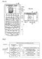
- FIGS. 1A and 1B are front views illustrating the configuration of the external appearance of a figure plotting device 10 according to an embodiment
- FIG. 1A is view in the case of implementing a graphing calculator 10F as the figure plotting device 10
- FIG. 1B is view in the case of implementing a tablet terminal 10T as the figure plotting device 10, respectively.
- FIG. 10 As the figure plotting device 10, besides the graphing calculator 10F and the tablet terminal 10T, other devices having a figure plotting function (having a figure display control program) such as a personal computer, a smart phone, a portable phone, a touch panel type personal digital assistant (PDA), an e-book, and a portable game console can be configured.
- a figure plotting function having a figure display control program
- examples of the figure plotting device 10 like the tablet terminal 10T having no physical keys (buttons) unlike the graphing calculator 10F display a software keyboard similar to keys of the graphing calculator 10F, and performs processing according to key operations on the software keyboard.
- the graphing calculator 10F is configured in such a small size that a user can hold it with one hand and operate it with one hand, due to the necessity of portability, and a key input unit 11 and a display output unit (a display unit) 12 are provided on the front surface of the main body of the graphing calculator 10F.
- the key input unit 11 includes a number/operation-symbol key group 111 for inputting numerical values or mathematical expressions, or issuing a calculation performance instruction, an arithmetic-function function key group 112 for inputting various arithmetic functions or starting a memory function, a mode setting key group 113 for displaying a menu screen ofvarious operating modes or issuing an operating-mode setting instruction, a function key group 114 for starting various functions displayed along the lower end of the display output unit 12 by one key operation, and a cursor key 115 for performing various operations such as an operation to move a cursor displayed on the display output unit 12 and an operation to select a data item.
- an "x 2 " key (a square key), a "sin” (sine) key, a “cos” (cosine) key, a “tan” (tangent) key, and so on are arranged.
- a "MENU” (menu) key As the mode setting key group 113, a "MENU” (menu) key, and a “SHIFT” (shift) key, an "OPTN” (option) key, and so on are arranged.
- each key of the number/operation-symbol key group 111, the arithmetic-function function key group 112, and the mode setting key group 113 is configured so as to be able to act as a key for a function written above the corresponding key, not a function written on the corresponding key, if the corresponding key is operated after the "SHIFT" key is operated.
- an operation on the "AC” key after an operation on the "SHIFT' key acts as an "OFF" (power-off) key.
- a “SHIFT”+"MENU” key acts as a “SET UP” (set up) key, and a “SHIFT” + “F3” key acts as a "V-Window” (view window) key (for instructing display of a plotting-area setting screen Gv).
- the display output unit 12 is composed of a dot matrix type liquid crystal display unit. Also, the display output unit 12 of the tablet terminal 10T is composed of a liquid crystal display unit superimposed on a touch panel.
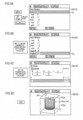
- FIG. 2 is a block diagram illustrating the electronic circuit configuration of the figure plotting device 10 (10F or 10T).
- the electronic circuit of the figure plotting device 10 includes not only the key input unit 11 and the display output unit 12 but also a CPU 21 which is a computer, a memory 22, a recording-medium reading unit 24, and a communication unit 25.
- the CPU 21 controls operations of the individual units of the circuit according to the figure display control program 22a stored in the memory 22, thereby performing various calculation processes based on key input signals from the key input unit 11.
- the figure display control program 22a may be stored in the memory 22 in advance, or may be a program read from an external recording medium 23 such as a memory card through the recording-medium reading unit 13 and stored in the memory 22. Even if the user operates the key input unit 11, the figure display control program 22a is not rewritten.
- the memory 22 has an area for storing data which the user can rewrite such as data on mathematical expressions, table data, and graph data, other than such information which the user cannot rewrite. If the user sequentially inputs key code data by operating the keys of the key input unit 11, whereby data is created by the key code data, the created data is stored in that area.
- the area of the memory 22 for storing data which the user can rewrite includes a V-Window data area 22b, a figure data area 22c, a figure plotting data area 22d, and a display data area 22e.
- a plotting-area setting screen Gv (see FIGS. 6A and 6B ) (here, a plotting-area setting screen Gv for plotting 3D figures) is displayed on the display output unit 12. Then, if the user inputs data on a 3D coordinate plotting area Ad (Xmin, Xmax, Ymin, Ymax, Zmin, and Zmax) for plotting 3D figures and a division number for grids (polygons) by performing operations on the plotting-area setting screen, the input data is stored in the V-Window data area 22b.
- MENU "MENU" (menu) key
- an operation menu (not shown in the drawings) is displayed, and if the user selects an icon "3D-Graph" for plotting a 3D figure from the operation menu, a 3D graph setting screen Gs (see FIG. 6C ) (here, a 3D graph setting screen Gs for plotting a circular cylinder) is displayed on the display output unit 12.
- the user inputs data on a 3D figure (plotting data (the radius R, the height Z, and the coordinates X and Y of the center) for modeling the figure with reference to the plotting area Ad) by operating the 3D graph setting screen, the input data is stored in the figure data area 22c.
- plotting data on the 3D figure (the coordinates of the apexes of individual grids (polygonal grids) constituting grid sets to constitute the surfaces of the 3D figure) is generated, and the generated data is stored in the figure plotting data area 22d.
- the display data area 22e includes a memory area corresponding to the display size of the liquid crystal display unit constituting the display output unit 12, and in this memory area, display data to be displayed on the liquid crystal display unit is stored as bitmap data (here, bitmap data developed according to the data on the plotting area and the data on the 3D figure).
- the CPU 21 controls operations of the individual circuit units according to commands described in the figure display control program 22a such that software and hardware operate in cooperation with each other, whereby the figure plotting device 10 (10F or 10T) configured as described above implements a figure plotting function to be described in the following operation description.
- FIG. 3 is a flow chart illustrating a circular-cylinder plotting process which is performed according to the figure display control program 22a of the figure plotting device 10.
- FIG. 4 is a flow chart illustrating a circle plotting process included in the circular-cylinder plotting process of the figure plotting device 10.
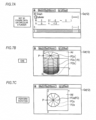
- FIGS. 5Ato 5D are views illustrating the relation between individual grids constituting a circle and a plotting area Ad when the grids are plotted in the circle plotting process of the figure plotting device 10.
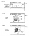
- FIGS. 6A to 8C are views illustrating display operations (first to third examples) corresponding to user's operations according to the circular-cylinder plotting process of the figure plotting device 10.
- a 3D-coordinate string constituting the circumference of one circle (an upper lid) and a 3D-coordinate string constituting the circumference of the other circle (a lower lid) are calculated by arithmetic processing (wherein the circles correspond to the data on the circular cylinder). Also, coordinate strings constituting lines connecting the calculated coordinate string corresponding to the one circle and the calculated coordinate string corresponding to the other circle are calculated as coordinate strings constituting the side surface of the circular cylinder by arithmetic processing.
- points of coordinates included in the calculated coordinate string corresponding to the one circle, the calculated coordinate string corresponding to the other circle, and the coordinate strings corresponding to the side surface of the circular cylinder and included in the plotting area are plotted in the order of the one circle, the other circle, and the side surface, whereby the set circular cylinder is displayed.
- division is performed along radial lines connecting the coordinate point of the center of the corresponding circle with individual coordinate points corresponding to the circumference of the corresponding circle, and lines connecting the individual coordinate points of the circumference of the corresponding circle, whereby a number of triangles are formed, and the set of the formed triangles constitutes the surface of the corresponding circle.
- division is performed along lines connecting the individual coordinate points corresponding to the circumference of the one circle with the individual coordinate points corresponding to the circumference of the other circle, whereby a number of quadrangles (grids) are formed, and the set of the formed quadrangles (grids) constitutes the surface of the side surface.
- the side surface is divided into quadrangles in horizontal directions (X-Y directions) and vertical directions (Z directions) along vertical lines connecting coordinate points constituting the individual triangles obtained by dividing the one circle and positioned on the circumference of the one circle with coordinate points constituting the individual triangles obtained by dividing the other circle and positioned on the circumference of the other circle and horizontal lines dividing a part between the one circle and the other circle according to the set division number, and the coordinates of the apexes of the individual quadrangles are determined, and the side surface is plotted.
- the plotting-area setting screen Gv for plotting 3D figures is displayed on the display output unit 12.
- a 3D graph setting screen Gs for plotting circular cylinders is displayed on the display output unit 12.
- the user inputs data on a circular cylinder by operating the 3D graph setting screen Gs, in other words, if the user inputs "2", “-2”, “2", “0”, and “0” as the radius R, the minimum value and the maximum value in the height direction (the Z direction), and the X and Y coordinates of the center, respectively, the input data (the radius R "2", the maximum value “2” and the minimum value "-2” in the height direction (the Z direction), and the X and Y coordinates (0, 0)) on the circular cylinder is stored in the figure data area 22c (STEP S2).
- the X and Y coordinates (0, 0) of the center defined in the data on the circular cylinder are determined as the coordinates of an intersection 1 with a triangle to constitute the circle which is a plotting object (STEP A2), and whether the coordinates of the intersection 1 (the X and Y coordinates (0, 0) of the center of the circle) is inside a horizontal plotting area (between Xmin "-3" and Xmax "3" and between Ymin "-3" and Ymax "3") defined in the data of the plotting area Ad is determined (STEP A3).
- the circular cylinder in a circular-cylinder plotting process of the second example, is like a circular cylinder obtained by shifting the center of the circular cylinder FC plotted in the first example in the Y direction by -1.2; however, in each of the upper circle plotting process and the lower circle plotting process shown in FIG.
- the X and Y coordinates of the intersection 2 (or 3) which is the intersection P (having X and Y coordinates (0, -3.2)) determined as being outside the plotting area are shifted to X and Y coordinates (here, (0, -3)) closest thereto and positioned in the plotting area (between Xmin "-3" and Xmax "3" and between Ymin "-3” and Ymax "3") as shown in FIGS. 5B and 5C (STEP A82).
- FIG. 7C shows a display state which is obtained by performing a process of rotating the plotted circular cylinder FC shown in FIG. 7B in a planar direction.
- rectangles of the side surface FCs positioned between two triangles of the upper circle FCa and two triangles of the lower circle FCb including the intersections P which are coordinate points 2 (or 3) shifted into the plotting area Ad have not been plotted for the purpose of convenience; however, they may be plotted.
- the circular cylinder is like a circular cylinder obtained by shifting the center of the circular cylinder FC plotted in the first example in the Y direction by -1.2 and increasing the height of the circular cylinder FC in the Z direction by "+2" such that a minimum value and a maximum value in the Z direction become -2 and 4, respectively. Therefore, in the circular-cylinder plotting process shown in FIG. 3 , it is determined that the upper circle FCa of the circular cylinder is outside the plotting area Ad ("No" in STEP S3).
- the X and Y coordinates of the intersection 2 (or 3) which is the intersection P (having X and Y coordinates (0, -3.2)) determined as being outside the plotting area are shifted to X and Y coordinates (here, (0, -3)) closest thereto and positioned in the plotting area (between Xmin "-3" and Xmax "3" and between Ymin "-3” and Ymax "3") as shown in FIGS. 5B and 5C (STEP A82).
- FIG. 8C shows a display state which is obtained by performing a process of rotating the plotted circular cylinder FC shown in FIG. 8B in a planar direction.
- rectangles of the side surface FCs corresponding to two triangles of the lower circle FCb including a intersection P which is a coordinate point 2 (or 3) shifted into the plotting area Ad have not been plotted for the purpose of convenience; however, they may be plotted.
- the user sets data on a 3D figure plotting area Ad (Xmin, Xmax, Ymin, Ymax, Zmin, and Zmax) according to the plotting-area setting screen Gv, and inputs plotting data on a circular cylinder FC (the radius R, the height in the Z direction, and the X and Y coordinates of the center) according to the 3D graph setting screen Gs.
- Ad 3D figure plotting area
- FC the radius R, the height in the Z direction, and the X and Y coordinates of the center
- the coordinates of individual intersections of the circumference of the corresponding circle with individual lines extending radially from the coordinates of the center of the corresponding circle at intervals of ⁇ are determined on the basis of the data on the plotting area Ad and the plotting data on the circular cylinder FC, and a plurality of triangles is formed by connecting the coordinates of the center with the coordinates of each of the intersections and connecting the coordinates of the individual intersections, and the corresponding circle FCa or FCb is plotted by the set of the triangles.
- quadrangles are formed by lines connecting the coordinates of the individual intersections determined on the circumference of one circle FCa of the circular cylinder FC with the coordinates of the individual intersections determined on the circumference of the other circle FCb and a plurality of dividing lines parallel to the circles FCa and FCb, and the side surface FCs is plotted by the set of the quadrangles.
- a figure having circles may include elliptic cylinders having ellipses at both ends, cones, elliptic cones, spheres, and elliptic spheres.
- the coordinate point positioned outside the plotting area may be shifted to a coordinate point closest thereto and positioned in the plotting area, and the corresponding circle may be plotted.
- the upper surface and the lower surface may not be circular, and may have any other shape which can be formed by connecting a plurality of points.
- examples of such a shape include circles and polygons, i.e. shapes which can be formed by connecting points with straight lines or curved lines.
- this technology can also be used in the case of plotting side surfaces of circular cylinders and in the case of plotting figures other than circular cylinders.
- a plane which is a plotting object included in the figure is divided into two or more predetermined shapes (wherein each predetermined shape is a polygon) each of which can be formed by connecting a plurality of points, such that grids are formed, and a shape which can be formed by connecting the plurality of points (in the case of the polygon, a plurality of apexes (The same is true in the following parentheses)) and the centroid point of the predetermined shape is plotted, whereby the predetermined shape (the polygon) is plotted in a plotting area of a display screen ofthe display unit.
- another shape different from the predetermined shape may be plotted, wherein the another shape can be formed by shifting each point positioned outside the plotting area to a point in the plotting area and connecting the at least one shifted point of the plurality of apexes of the polygon and one or more points, having not been shifted, of the plurality of points of the predetermined shape (the plurality of apexes of the polygon).
- all of the methods of the individual processes which are performed by the figure plotting device 10 described can be configured as programs executable in a computer, and the programs can be stored in media of external recording devices, such as memory cards (such as ROM cards and RAM cards), magnetic disks (such as floppy (registered as a trade mark) disks and hard disks), optical disks (such as CD-ROMs and DVDs), and semiconductor memories, to distributed.
- external recording devices such as memory cards (such as ROM cards and RAM cards), magnetic disks (such as floppy (registered as a trade mark) disks and hard disks), optical disks (such as CD-ROMs and DVDs), and semiconductor memories, to distributed.
- a computer of an electronic device having a display function can read the programs recorded on a medium of an external recording device, and can control operations according to the read programs, thereby implementing the function of plotting figures having circles described in each embodiment, and performing the same processes according to the above-described methods.
- data on the programs for realizing the methods may be transmitted in a program code form on a communication network (N), and the program data may be downloaded from a computer device (a program server) connected to the communication network (N), into a storage device of an electronic device having a display function, such that it is possible to realize the above-described function of plotting figures having circles.
Landscapes
- Engineering & Computer Science (AREA)
- Theoretical Computer Science (AREA)
- Physics & Mathematics (AREA)
- General Engineering & Computer Science (AREA)
- General Physics & Mathematics (AREA)
- Human Computer Interaction (AREA)
- Computer Hardware Design (AREA)
- Computing Systems (AREA)
- Geometry (AREA)
- Software Systems (AREA)
- Computer Graphics (AREA)
- Image Generation (AREA)
- Processing Or Creating Images (AREA)
- Calculators And Similar Devices (AREA)
- User Interface Of Digital Computer (AREA)
- Time Recorders, Dirve Recorders, Access Control (AREA)
Applications Claiming Priority (1)
| Application Number | Priority Date | Filing Date | Title |
|---|---|---|---|
| JP2016250412A JP6708117B2 (ja) | 2016-12-26 | 2016-12-26 | 図形描画装置、図形描画方法、サーバ装置、プログラム、及びプログラムを送信する方法 |
Publications (2)
| Publication Number | Publication Date |
|---|---|
| EP3340179A1 EP3340179A1 (en) | 2018-06-27 |
| EP3340179B1 true EP3340179B1 (en) | 2023-05-03 |
Family
ID=60971915
Family Applications (1)
| Application Number | Title | Priority Date | Filing Date |
|---|---|---|---|
| EP17210320.2A Active EP3340179B1 (en) | 2016-12-26 | 2017-12-22 | Figure plotting device, figure plotting method, and recording medium |
Country Status (7)
| Country | Link |
|---|---|
| US (1) | US20180182138A1 (enExample) |
| EP (1) | EP3340179B1 (enExample) |
| JP (1) | JP6708117B2 (enExample) |
| CN (1) | CN108241462B (enExample) |
| AU (1) | AU2017279801B2 (enExample) |
| ES (1) | ES2946786T3 (enExample) |
| PT (1) | PT3340179T (enExample) |
Families Citing this family (1)
| Publication number | Priority date | Publication date | Assignee | Title |
|---|---|---|---|---|
| JP6939135B2 (ja) * | 2017-06-23 | 2021-09-22 | カシオ計算機株式会社 | 電子機器、プログラム、サーバ、グラフ画像生成方法およびグラフ画像生成システム |
Citations (3)
| Publication number | Priority date | Publication date | Assignee | Title |
|---|---|---|---|---|
| US20010043211A1 (en) * | 2000-04-12 | 2001-11-22 | Yasushi Niitsu | Method for three-dimensional solid graphic generation and record medium of three-dimensional solid graphic generation |
| US20090073180A1 (en) * | 2007-09-13 | 2009-03-19 | Fujitsu Microelectronics Limited | Graphics drawing apparatus, method, and program and recording medium on which the program is recorded |
| JP2013203006A (ja) * | 2012-03-29 | 2013-10-07 | Oki Data Corp | 画像形成装置 |
Family Cites Families (15)
| Publication number | Priority date | Publication date | Assignee | Title |
|---|---|---|---|---|
| JPS6232575A (ja) * | 1985-08-06 | 1987-02-12 | Mitsubishi Electric Corp | 図形入力方式 |
| JPH03141479A (ja) * | 1989-10-27 | 1991-06-17 | Hitachi Ltd | 三次元図形表示方法及びその装置 |
| US5491779A (en) * | 1992-04-03 | 1996-02-13 | Bezjian; Richard D. | Three dimensional presentation of multiple data sets in unitary format with pie charts |
| JPH07225849A (ja) * | 1993-12-17 | 1995-08-22 | Hitachi Ltd | グラフィックスコンピュータと直線描画装置 |
| JPH07220098A (ja) * | 1994-01-28 | 1995-08-18 | Nippon Avionics Co Ltd | 多角形近似による円弧の描画データ作成装置 |
| JP3138390B2 (ja) * | 1994-08-08 | 2001-02-26 | シャープ株式会社 | 図形描画装置 |
| JP2002108621A (ja) * | 2000-09-28 | 2002-04-12 | Casio Comput Co Ltd | プログラム配信システム、及び記憶媒体 |
| JP2005182125A (ja) | 2003-12-16 | 2005-07-07 | Casio Comput Co Ltd | グラフ表示制御装置及びプログラム |
| US7408548B2 (en) * | 2005-06-30 | 2008-08-05 | Microsoft Corporation | Triangulating procedural geometric objects |
| US8161040B2 (en) * | 2007-04-30 | 2012-04-17 | Piffany, Inc. | Criteria-specific authority ranking |
| EP2731078B1 (en) * | 2011-07-06 | 2017-12-13 | The University of Tokyo | Shape extraction method and shape extraction system |
| CN103164867A (zh) * | 2011-12-09 | 2013-06-19 | 金耀有限公司 | 三维图形数据处理方法和装置 |
| JP5835255B2 (ja) * | 2013-03-19 | 2015-12-24 | カシオ計算機株式会社 | グラフ表示装置及びグラフ表示プログラム |
| US20150169758A1 (en) * | 2013-12-17 | 2015-06-18 | Luigi ASSOM | Multi-partite graph database |
| CN105787986A (zh) * | 2016-02-29 | 2016-07-20 | 浪潮(苏州)金融技术服务有限公司 | 一种三维图形渲染的方法和装置 |
-
2016
- 2016-12-26 JP JP2016250412A patent/JP6708117B2/ja active Active
-
2017
- 2017-12-21 US US15/849,892 patent/US20180182138A1/en not_active Abandoned
- 2017-12-22 EP EP17210320.2A patent/EP3340179B1/en active Active
- 2017-12-22 AU AU2017279801A patent/AU2017279801B2/en active Active
- 2017-12-22 PT PT172103202T patent/PT3340179T/pt unknown
- 2017-12-22 ES ES17210320T patent/ES2946786T3/es active Active
- 2017-12-26 CN CN201711431400.8A patent/CN108241462B/zh active Active
Patent Citations (3)
| Publication number | Priority date | Publication date | Assignee | Title |
|---|---|---|---|---|
| US20010043211A1 (en) * | 2000-04-12 | 2001-11-22 | Yasushi Niitsu | Method for three-dimensional solid graphic generation and record medium of three-dimensional solid graphic generation |
| US20090073180A1 (en) * | 2007-09-13 | 2009-03-19 | Fujitsu Microelectronics Limited | Graphics drawing apparatus, method, and program and recording medium on which the program is recorded |
| JP2013203006A (ja) * | 2012-03-29 | 2013-10-07 | Oki Data Corp | 画像形成装置 |
Also Published As
| Publication number | Publication date |
|---|---|
| AU2017279801B2 (en) | 2022-11-24 |
| CN108241462A (zh) | 2018-07-03 |
| JP2018106321A (ja) | 2018-07-05 |
| EP3340179A1 (en) | 2018-06-27 |
| AU2017279801A1 (en) | 2018-07-12 |
| ES2946786T3 (es) | 2023-07-26 |
| CN108241462B (zh) | 2021-04-27 |
| US20180182138A1 (en) | 2018-06-28 |
| PT3340179T (pt) | 2023-05-29 |
| JP6708117B2 (ja) | 2020-06-10 |
Similar Documents
| Publication | Publication Date | Title |
|---|---|---|
| US9870144B2 (en) | Graph display apparatus, graph display method and storage medium | |
| US20120206471A1 (en) | Systems, methods, and computer-readable media for managing layers of graphical object data | |
| KR20160046150A (ko) | 도형 컨텐트를 생성 및 해석하는 방법 및 장치 | |
| KR20140070040A (ko) | 터치스크린 상에 표시되는 복수의 객체들을 관리하는 장치 및 방법 | |
| EP2237230B1 (en) | Graph display control apparatus and graph display control method | |
| WO2012137861A1 (ja) | 電子機器、表示方法、および表示プログラム | |
| JP2017058972A (ja) | 情報処理装置、その表示方法、及びコンピュータが実行可能なプログラム | |
| JP2004118727A (ja) | 図形表示制御装置及びプログラム | |
| JP6965518B2 (ja) | 描画方法、描画装置、及びプログラム | |
| EP3340179B1 (en) | Figure plotting device, figure plotting method, and recording medium | |
| US10460528B2 (en) | Figure drawing apparatus, control method of figure drawing apparatus, and recording medium | |
| US9047707B2 (en) | Graph display device | |
| US11210822B2 (en) | Display apparatus, display method, and storage medium for displaying distinct display of relative position of specific point to three-dimensional range in three dimensional coordinate system | |
| JP5287588B2 (ja) | 図形表示装置およびプログラム | |
| JP6142553B2 (ja) | 図形表示制御装置、図形表示制御方法及びプログラム | |
| JP5617961B2 (ja) | 図形表示装置およびプログラム |
Legal Events
| Date | Code | Title | Description |
|---|---|---|---|
| PUAI | Public reference made under article 153(3) epc to a published international application that has entered the european phase |
Free format text: ORIGINAL CODE: 0009012 |
|
| STAA | Information on the status of an ep patent application or granted ep patent |
Free format text: STATUS: REQUEST FOR EXAMINATION WAS MADE |
|
| 17P | Request for examination filed |
Effective date: 20171222 |
|
| AK | Designated contracting states |
Kind code of ref document: A1 Designated state(s): AL AT BE BG CH CY CZ DE DK EE ES FI FR GB GR HR HU IE IS IT LI LT LU LV MC MK MT NL NO PL PT RO RS SE SI SK SM TR |
|
| AX | Request for extension of the european patent |
Extension state: BA ME |
|
| STAA | Information on the status of an ep patent application or granted ep patent |
Free format text: STATUS: EXAMINATION IS IN PROGRESS |
|
| 17Q | First examination report despatched |
Effective date: 20201022 |
|
| GRAP | Despatch of communication of intention to grant a patent |
Free format text: ORIGINAL CODE: EPIDOSNIGR1 |
|
| STAA | Information on the status of an ep patent application or granted ep patent |
Free format text: STATUS: GRANT OF PATENT IS INTENDED |
|
| INTG | Intention to grant announced |
Effective date: 20221208 |
|
| GRAS | Grant fee paid |
Free format text: ORIGINAL CODE: EPIDOSNIGR3 |
|
| GRAA | (expected) grant |
Free format text: ORIGINAL CODE: 0009210 |
|
| STAA | Information on the status of an ep patent application or granted ep patent |
Free format text: STATUS: THE PATENT HAS BEEN GRANTED |
|
| AK | Designated contracting states |
Kind code of ref document: B1 Designated state(s): AL AT BE BG CH CY CZ DE DK EE ES FI FR GB GR HR HU IE IS IT LI LT LU LV MC MK MT NL NO PL PT RO RS SE SI SK SM TR |
|
| REG | Reference to a national code |
Ref country code: GB Ref legal event code: FG4D |
|
| REG | Reference to a national code |
Ref country code: DE Ref legal event code: R096 Ref document number: 602017068259 Country of ref document: DE |
|
| REG | Reference to a national code |
Ref country code: AT Ref legal event code: REF Ref document number: 1565311 Country of ref document: AT Kind code of ref document: T Effective date: 20230515 Ref country code: CH Ref legal event code: EP |
|
| REG | Reference to a national code |
Ref country code: IE Ref legal event code: FG4D |
|
| REG | Reference to a national code |
Ref country code: PT Ref legal event code: SC4A Ref document number: 3340179 Country of ref document: PT Date of ref document: 20230529 Kind code of ref document: T Free format text: AVAILABILITY OF NATIONAL TRANSLATION Effective date: 20230522 |
|
| REG | Reference to a national code |
Ref country code: NL Ref legal event code: FP |
|
| REG | Reference to a national code |
Ref country code: ES Ref legal event code: FG2A Ref document number: 2946786 Country of ref document: ES Kind code of ref document: T3 Effective date: 20230726 |
|
| REG | Reference to a national code |
Ref country code: LT Ref legal event code: MG9D |
|
| REG | Reference to a national code |
Ref country code: AT Ref legal event code: MK05 Ref document number: 1565311 Country of ref document: AT Kind code of ref document: T Effective date: 20230503 |
|
| PG25 | Lapsed in a contracting state [announced via postgrant information from national office to epo] |
Ref country code: SE Free format text: LAPSE BECAUSE OF FAILURE TO SUBMIT A TRANSLATION OF THE DESCRIPTION OR TO PAY THE FEE WITHIN THE PRESCRIBED TIME-LIMIT Effective date: 20230503 Ref country code: NO Free format text: LAPSE BECAUSE OF FAILURE TO SUBMIT A TRANSLATION OF THE DESCRIPTION OR TO PAY THE FEE WITHIN THE PRESCRIBED TIME-LIMIT Effective date: 20230803 Ref country code: AT Free format text: LAPSE BECAUSE OF FAILURE TO SUBMIT A TRANSLATION OF THE DESCRIPTION OR TO PAY THE FEE WITHIN THE PRESCRIBED TIME-LIMIT Effective date: 20230503 |
|
| PG25 | Lapsed in a contracting state [announced via postgrant information from national office to epo] |
Ref country code: RS Free format text: LAPSE BECAUSE OF FAILURE TO SUBMIT A TRANSLATION OF THE DESCRIPTION OR TO PAY THE FEE WITHIN THE PRESCRIBED TIME-LIMIT Effective date: 20230503 Ref country code: PL Free format text: LAPSE BECAUSE OF FAILURE TO SUBMIT A TRANSLATION OF THE DESCRIPTION OR TO PAY THE FEE WITHIN THE PRESCRIBED TIME-LIMIT Effective date: 20230503 Ref country code: LV Free format text: LAPSE BECAUSE OF FAILURE TO SUBMIT A TRANSLATION OF THE DESCRIPTION OR TO PAY THE FEE WITHIN THE PRESCRIBED TIME-LIMIT Effective date: 20230503 Ref country code: LT Free format text: LAPSE BECAUSE OF FAILURE TO SUBMIT A TRANSLATION OF THE DESCRIPTION OR TO PAY THE FEE WITHIN THE PRESCRIBED TIME-LIMIT Effective date: 20230503 Ref country code: IS Free format text: LAPSE BECAUSE OF FAILURE TO SUBMIT A TRANSLATION OF THE DESCRIPTION OR TO PAY THE FEE WITHIN THE PRESCRIBED TIME-LIMIT Effective date: 20230903 Ref country code: HR Free format text: LAPSE BECAUSE OF FAILURE TO SUBMIT A TRANSLATION OF THE DESCRIPTION OR TO PAY THE FEE WITHIN THE PRESCRIBED TIME-LIMIT Effective date: 20230503 Ref country code: GR Free format text: LAPSE BECAUSE OF FAILURE TO SUBMIT A TRANSLATION OF THE DESCRIPTION OR TO PAY THE FEE WITHIN THE PRESCRIBED TIME-LIMIT Effective date: 20230804 |
|
| PG25 | Lapsed in a contracting state [announced via postgrant information from national office to epo] |
Ref country code: FI Free format text: LAPSE BECAUSE OF FAILURE TO SUBMIT A TRANSLATION OF THE DESCRIPTION OR TO PAY THE FEE WITHIN THE PRESCRIBED TIME-LIMIT Effective date: 20230503 |
|
| PG25 | Lapsed in a contracting state [announced via postgrant information from national office to epo] |
Ref country code: SK Free format text: LAPSE BECAUSE OF FAILURE TO SUBMIT A TRANSLATION OF THE DESCRIPTION OR TO PAY THE FEE WITHIN THE PRESCRIBED TIME-LIMIT Effective date: 20230503 |
|
| PG25 | Lapsed in a contracting state [announced via postgrant information from national office to epo] |
Ref country code: SM Free format text: LAPSE BECAUSE OF FAILURE TO SUBMIT A TRANSLATION OF THE DESCRIPTION OR TO PAY THE FEE WITHIN THE PRESCRIBED TIME-LIMIT Effective date: 20230503 Ref country code: SK Free format text: LAPSE BECAUSE OF FAILURE TO SUBMIT A TRANSLATION OF THE DESCRIPTION OR TO PAY THE FEE WITHIN THE PRESCRIBED TIME-LIMIT Effective date: 20230503 Ref country code: RO Free format text: LAPSE BECAUSE OF FAILURE TO SUBMIT A TRANSLATION OF THE DESCRIPTION OR TO PAY THE FEE WITHIN THE PRESCRIBED TIME-LIMIT Effective date: 20230503 Ref country code: EE Free format text: LAPSE BECAUSE OF FAILURE TO SUBMIT A TRANSLATION OF THE DESCRIPTION OR TO PAY THE FEE WITHIN THE PRESCRIBED TIME-LIMIT Effective date: 20230503 Ref country code: DK Free format text: LAPSE BECAUSE OF FAILURE TO SUBMIT A TRANSLATION OF THE DESCRIPTION OR TO PAY THE FEE WITHIN THE PRESCRIBED TIME-LIMIT Effective date: 20230503 Ref country code: CZ Free format text: LAPSE BECAUSE OF FAILURE TO SUBMIT A TRANSLATION OF THE DESCRIPTION OR TO PAY THE FEE WITHIN THE PRESCRIBED TIME-LIMIT Effective date: 20230503 |
|
| REG | Reference to a national code |
Ref country code: DE Ref legal event code: R097 Ref document number: 602017068259 Country of ref document: DE |
|
| PLBE | No opposition filed within time limit |
Free format text: ORIGINAL CODE: 0009261 |
|
| STAA | Information on the status of an ep patent application or granted ep patent |
Free format text: STATUS: NO OPPOSITION FILED WITHIN TIME LIMIT |
|
| 26N | No opposition filed |
Effective date: 20240206 |
|
| PG25 | Lapsed in a contracting state [announced via postgrant information from national office to epo] |
Ref country code: SI Free format text: LAPSE BECAUSE OF FAILURE TO SUBMIT A TRANSLATION OF THE DESCRIPTION OR TO PAY THE FEE WITHIN THE PRESCRIBED TIME-LIMIT Effective date: 20230503 |
|
| PG25 | Lapsed in a contracting state [announced via postgrant information from national office to epo] |
Ref country code: SI Free format text: LAPSE BECAUSE OF FAILURE TO SUBMIT A TRANSLATION OF THE DESCRIPTION OR TO PAY THE FEE WITHIN THE PRESCRIBED TIME-LIMIT Effective date: 20230503 |
|
| REG | Reference to a national code |
Ref country code: CH Ref legal event code: PL |
|
| PG25 | Lapsed in a contracting state [announced via postgrant information from national office to epo] |
Ref country code: LU Free format text: LAPSE BECAUSE OF NON-PAYMENT OF DUE FEES Effective date: 20231222 |
|
| PG25 | Lapsed in a contracting state [announced via postgrant information from national office to epo] |
Ref country code: MC Free format text: LAPSE BECAUSE OF FAILURE TO SUBMIT A TRANSLATION OF THE DESCRIPTION OR TO PAY THE FEE WITHIN THE PRESCRIBED TIME-LIMIT Effective date: 20230503 |
|
| REG | Reference to a national code |
Ref country code: BE Ref legal event code: MM Effective date: 20231231 |
|
| PG25 | Lapsed in a contracting state [announced via postgrant information from national office to epo] |
Ref country code: MC Free format text: LAPSE BECAUSE OF FAILURE TO SUBMIT A TRANSLATION OF THE DESCRIPTION OR TO PAY THE FEE WITHIN THE PRESCRIBED TIME-LIMIT Effective date: 20230503 Ref country code: LU Free format text: LAPSE BECAUSE OF NON-PAYMENT OF DUE FEES Effective date: 20231222 |
|
| REG | Reference to a national code |
Ref country code: IE Ref legal event code: MM4A |
|
| PG25 | Lapsed in a contracting state [announced via postgrant information from national office to epo] |
Ref country code: IE Free format text: LAPSE BECAUSE OF NON-PAYMENT OF DUE FEES Effective date: 20231222 |
|
| PG25 | Lapsed in a contracting state [announced via postgrant information from national office to epo] |
Ref country code: BE Free format text: LAPSE BECAUSE OF NON-PAYMENT OF DUE FEES Effective date: 20231231 |
|
| PG25 | Lapsed in a contracting state [announced via postgrant information from national office to epo] |
Ref country code: CH Free format text: LAPSE BECAUSE OF NON-PAYMENT OF DUE FEES Effective date: 20231231 |
|
| PG25 | Lapsed in a contracting state [announced via postgrant information from national office to epo] |
Ref country code: IE Free format text: LAPSE BECAUSE OF NON-PAYMENT OF DUE FEES Effective date: 20231222 Ref country code: CH Free format text: LAPSE BECAUSE OF NON-PAYMENT OF DUE FEES Effective date: 20231231 Ref country code: BE Free format text: LAPSE BECAUSE OF NON-PAYMENT OF DUE FEES Effective date: 20231231 |
|
| PG25 | Lapsed in a contracting state [announced via postgrant information from national office to epo] |
Ref country code: BG Free format text: LAPSE BECAUSE OF FAILURE TO SUBMIT A TRANSLATION OF THE DESCRIPTION OR TO PAY THE FEE WITHIN THE PRESCRIBED TIME-LIMIT Effective date: 20230503 |
|
| PG25 | Lapsed in a contracting state [announced via postgrant information from national office to epo] |
Ref country code: BG Free format text: LAPSE BECAUSE OF FAILURE TO SUBMIT A TRANSLATION OF THE DESCRIPTION OR TO PAY THE FEE WITHIN THE PRESCRIBED TIME-LIMIT Effective date: 20230503 |
|
| PGFP | Annual fee paid to national office [announced via postgrant information from national office to epo] |
Ref country code: DE Payment date: 20241029 Year of fee payment: 8 |
|
| PGFP | Annual fee paid to national office [announced via postgrant information from national office to epo] |
Ref country code: PT Payment date: 20241223 Year of fee payment: 8 |
|
| PGFP | Annual fee paid to national office [announced via postgrant information from national office to epo] |
Ref country code: GB Payment date: 20241104 Year of fee payment: 8 |
|
| PGFP | Annual fee paid to national office [announced via postgrant information from national office to epo] |
Ref country code: FR Payment date: 20241111 Year of fee payment: 8 |
|
| PGFP | Annual fee paid to national office [announced via postgrant information from national office to epo] |
Ref country code: IT Payment date: 20241112 Year of fee payment: 8 |
|
| PGFP | Annual fee paid to national office [announced via postgrant information from national office to epo] |
Ref country code: ES Payment date: 20250103 Year of fee payment: 8 |
|
| PG25 | Lapsed in a contracting state [announced via postgrant information from national office to epo] |
Ref country code: CY Free format text: LAPSE BECAUSE OF FAILURE TO SUBMIT A TRANSLATION OF THE DESCRIPTION OR TO PAY THE FEE WITHIN THE PRESCRIBED TIME-LIMIT; INVALID AB INITIO Effective date: 20171222 |
|
| PG25 | Lapsed in a contracting state [announced via postgrant information from national office to epo] |
Ref country code: HU Free format text: LAPSE BECAUSE OF FAILURE TO SUBMIT A TRANSLATION OF THE DESCRIPTION OR TO PAY THE FEE WITHIN THE PRESCRIBED TIME-LIMIT; INVALID AB INITIO Effective date: 20171222 |
|
| PG25 | Lapsed in a contracting state [announced via postgrant information from national office to epo] |
Ref country code: TR Free format text: LAPSE BECAUSE OF FAILURE TO SUBMIT A TRANSLATION OF THE DESCRIPTION OR TO PAY THE FEE WITHIN THE PRESCRIBED TIME-LIMIT Effective date: 20230503 |
|
| PGFP | Annual fee paid to national office [announced via postgrant information from national office to epo] |
Ref country code: NL Payment date: 20251112 Year of fee payment: 9 |