EP3339825B1 - Capteur d'échappement haute température - Google Patents
Capteur d'échappement haute température Download PDFInfo
- Publication number
- EP3339825B1 EP3339825B1 EP17153203.9A EP17153203A EP3339825B1 EP 3339825 B1 EP3339825 B1 EP 3339825B1 EP 17153203 A EP17153203 A EP 17153203A EP 3339825 B1 EP3339825 B1 EP 3339825B1
- Authority
- EP
- European Patent Office
- Prior art keywords
- tube
- sensing
- insulated cable
- mineral insulated
- sealing flange
- Prior art date
- Legal status (The legal status is an assumption and is not a legal conclusion. Google has not performed a legal analysis and makes no representation as to the accuracy of the status listed.)
- Active
Links
- 238000007789 sealing Methods 0.000 claims description 63
- 229910052500 inorganic mineral Inorganic materials 0.000 claims description 58
- 239000011707 mineral Substances 0.000 claims description 58
- 239000012530 fluid Substances 0.000 claims description 25
- 238000000034 method Methods 0.000 claims description 21
- 239000004020 conductor Substances 0.000 claims description 16
- 239000000395 magnesium oxide Substances 0.000 claims description 7
- CPLXHLVBOLITMK-UHFFFAOYSA-N magnesium oxide Inorganic materials [Mg]=O CPLXHLVBOLITMK-UHFFFAOYSA-N 0.000 claims description 7
- 230000008569 process Effects 0.000 claims description 7
- AXZKOIWUVFPNLO-UHFFFAOYSA-N magnesium;oxygen(2-) Chemical compound [O-2].[Mg+2] AXZKOIWUVFPNLO-UHFFFAOYSA-N 0.000 claims description 6
- 238000009413 insulation Methods 0.000 claims description 5
- 238000002788 crimping Methods 0.000 claims description 3
- 238000003825 pressing Methods 0.000 claims description 2
- 230000001681 protective effect Effects 0.000 description 9
- 239000000523 sample Substances 0.000 description 9
- 238000012546 transfer Methods 0.000 description 8
- 230000008901 benefit Effects 0.000 description 7
- 230000035939 shock Effects 0.000 description 7
- 238000005516 engineering process Methods 0.000 description 6
- 238000003466 welding Methods 0.000 description 6
- 239000007789 gas Substances 0.000 description 5
- 238000004519 manufacturing process Methods 0.000 description 3
- 230000005855 radiation Effects 0.000 description 3
- 238000012360 testing method Methods 0.000 description 3
- RYGMFSIKBFXOCR-UHFFFAOYSA-N Copper Chemical compound [Cu] RYGMFSIKBFXOCR-UHFFFAOYSA-N 0.000 description 2
- QVGXLLKOCUKJST-UHFFFAOYSA-N atomic oxygen Chemical compound [O] QVGXLLKOCUKJST-UHFFFAOYSA-N 0.000 description 2
- 238000002485 combustion reaction Methods 0.000 description 2
- 229910052802 copper Inorganic materials 0.000 description 2
- 239000010949 copper Substances 0.000 description 2
- 230000008878 coupling Effects 0.000 description 2
- 238000010168 coupling process Methods 0.000 description 2
- 238000005859 coupling reaction Methods 0.000 description 2
- 230000001419 dependent effect Effects 0.000 description 2
- 238000013461 design Methods 0.000 description 2
- 230000006872 improvement Effects 0.000 description 2
- 229910001026 inconel Inorganic materials 0.000 description 2
- 239000011810 insulating material Substances 0.000 description 2
- 229910052751 metal Inorganic materials 0.000 description 2
- 239000002184 metal Substances 0.000 description 2
- 239000001301 oxygen Substances 0.000 description 2
- 229910052760 oxygen Inorganic materials 0.000 description 2
- 230000004044 response Effects 0.000 description 2
- 239000010935 stainless steel Substances 0.000 description 2
- 229910001220 stainless steel Inorganic materials 0.000 description 2
- KOAWAWHSMVKCON-UHFFFAOYSA-N 6-[difluoro-(6-pyridin-4-yl-[1,2,4]triazolo[4,3-b]pyridazin-3-yl)methyl]quinoline Chemical compound C=1C=C2N=CC=CC2=CC=1C(F)(F)C(N1N=2)=NN=C1C=CC=2C1=CC=NC=C1 KOAWAWHSMVKCON-UHFFFAOYSA-N 0.000 description 1
- 239000000853 adhesive Substances 0.000 description 1
- 230000001070 adhesive effect Effects 0.000 description 1
- 229910045601 alloy Inorganic materials 0.000 description 1
- 239000000956 alloy Substances 0.000 description 1
- 238000005452 bending Methods 0.000 description 1
- 239000011230 binding agent Substances 0.000 description 1
- 230000008859 change Effects 0.000 description 1
- 238000010276 construction Methods 0.000 description 1
- 230000000694 effects Effects 0.000 description 1
- 239000012777 electrically insulating material Substances 0.000 description 1
- 238000002474 experimental method Methods 0.000 description 1
- 238000001125 extrusion Methods 0.000 description 1
- 239000000446 fuel Substances 0.000 description 1
- 239000012774 insulation material Substances 0.000 description 1
- 230000003993 interaction Effects 0.000 description 1
- 230000005923 long-lasting effect Effects 0.000 description 1
- 239000000463 material Substances 0.000 description 1
- 239000002557 mineral fiber Substances 0.000 description 1
- 238000012545 processing Methods 0.000 description 1
- 239000000126 substance Substances 0.000 description 1
- 238000005382 thermal cycling Methods 0.000 description 1
- 230000008542 thermal sensitivity Effects 0.000 description 1
- 230000007704 transition Effects 0.000 description 1
Images


Classifications
-
- F—MECHANICAL ENGINEERING; LIGHTING; HEATING; WEAPONS; BLASTING
- F01—MACHINES OR ENGINES IN GENERAL; ENGINE PLANTS IN GENERAL; STEAM ENGINES
- F01N—GAS-FLOW SILENCERS OR EXHAUST APPARATUS FOR MACHINES OR ENGINES IN GENERAL; GAS-FLOW SILENCERS OR EXHAUST APPARATUS FOR INTERNAL COMBUSTION ENGINES
- F01N11/00—Monitoring or diagnostic devices for exhaust-gas treatment apparatus, e.g. for catalytic activity
- F01N11/002—Monitoring or diagnostic devices for exhaust-gas treatment apparatus, e.g. for catalytic activity the diagnostic devices measuring or estimating temperature or pressure in, or downstream of the exhaust apparatus
-
- G—PHYSICS
- G01—MEASURING; TESTING
- G01K—MEASURING TEMPERATURE; MEASURING QUANTITY OF HEAT; THERMALLY-SENSITIVE ELEMENTS NOT OTHERWISE PROVIDED FOR
- G01K1/00—Details of thermometers not specially adapted for particular types of thermometer
- G01K1/08—Protective devices, e.g. casings
- G01K1/12—Protective devices, e.g. casings for preventing damage due to heat overloading
-
- G—PHYSICS
- G01—MEASURING; TESTING
- G01K—MEASURING TEMPERATURE; MEASURING QUANTITY OF HEAT; THERMALLY-SENSITIVE ELEMENTS NOT OTHERWISE PROVIDED FOR
- G01K13/00—Thermometers specially adapted for specific purposes
- G01K13/02—Thermometers specially adapted for specific purposes for measuring temperature of moving fluids or granular materials capable of flow
-
- G—PHYSICS
- G01—MEASURING; TESTING
- G01K—MEASURING TEMPERATURE; MEASURING QUANTITY OF HEAT; THERMALLY-SENSITIVE ELEMENTS NOT OTHERWISE PROVIDED FOR
- G01K7/00—Measuring temperature based on the use of electric or magnetic elements directly sensitive to heat ; Power supply therefor, e.g. using thermoelectric elements
- G01K7/02—Measuring temperature based on the use of electric or magnetic elements directly sensitive to heat ; Power supply therefor, e.g. using thermoelectric elements using thermoelectric elements, e.g. thermocouples
-
- F—MECHANICAL ENGINEERING; LIGHTING; HEATING; WEAPONS; BLASTING
- F01—MACHINES OR ENGINES IN GENERAL; ENGINE PLANTS IN GENERAL; STEAM ENGINES
- F01N—GAS-FLOW SILENCERS OR EXHAUST APPARATUS FOR MACHINES OR ENGINES IN GENERAL; GAS-FLOW SILENCERS OR EXHAUST APPARATUS FOR INTERNAL COMBUSTION ENGINES
- F01N2560/00—Exhaust systems with means for detecting or measuring exhaust gas components or characteristics
- F01N2560/06—Exhaust systems with means for detecting or measuring exhaust gas components or characteristics the means being a temperature sensor
-
- G—PHYSICS
- G01—MEASURING; TESTING
- G01K—MEASURING TEMPERATURE; MEASURING QUANTITY OF HEAT; THERMALLY-SENSITIVE ELEMENTS NOT OTHERWISE PROVIDED FOR
- G01K13/00—Thermometers specially adapted for specific purposes
- G01K13/02—Thermometers specially adapted for specific purposes for measuring temperature of moving fluids or granular materials capable of flow
- G01K13/024—Thermometers specially adapted for specific purposes for measuring temperature of moving fluids or granular materials capable of flow of moving gases
-
- G—PHYSICS
- G01—MEASURING; TESTING
- G01K—MEASURING TEMPERATURE; MEASURING QUANTITY OF HEAT; THERMALLY-SENSITIVE ELEMENTS NOT OTHERWISE PROVIDED FOR
- G01K2205/00—Application of thermometers in motors, e.g. of a vehicle
- G01K2205/04—Application of thermometers in motors, e.g. of a vehicle for measuring exhaust gas temperature
Definitions
- the subject disclosure relates to a sensing device for sensing a physical quantity of a fluid having a high temperature and a method for assembling such a sensing device. More particular the subject disclosure relates to high-temperature exhaust sensors. More specifically, this disclosure relates to a high temperature capable thermocouple.
- Internal combustion engines such as, but not limited to, diesel and gasoline engines, may include one or more temperature sensors at least partially disposed within the exhaust gas system. These temperature sensors may sense the temperature of the exhaust gas and may be used, at least in part, by an engine control system to adjust one or more properties of the engine such as, but not limited to, air/fuel ratio, boost pressure, timing or the like. Because of the operating environment, the temperature sensors may be exposed to relatively harsh conditions including, but not limited to, vibration, exposure to debris, moisture and corrosive chemicals, large temperature ranges, large temperature gradients, and relatively high continuous use operating temperatures.
- WO2011094753A2 discloses an exhaust gas temperature sensor comprising a temperature sensor coupled to an end of a mineral insulated cable. The cable is coupled to a stop flange. Furthermore, an anti-vibration sleeve is positioned between the stop flange and the temperature sensor.
- thermocouple devices are difficult to implement in an automotive-style system. These thermocouples are typically unable to operate for the extended life requirement in an automotive setting. This situation is compounded by the increasingly harsh application requirements, which can induce failure of conventional thermocouples. These failures are more likely in sensors with a long probe length or extended high-temperature operation with rapid temperature fluctuation of the fluid in which the probe is positioned.
- thermocouples create the need for a design solution that enables the use of thermocouples in automotive applications, specifically those requiring long probe length.
- FR3035500A1 describes a method for producing a probe for measuring the temperature of a part or a fluid.
- the probe comprises: a protective sleeve in which a temperature measuring element is installed.
- the sleeve has a closed end, a wire entry end, and an active part which in use is in contact with the part or fluid whose temperature is to be measured, a cable having a first end connected to the sleeve at the level of its input end and a second end adapted to be connected to an apparatus for processing the signals delivered by the measuring element.
- the flexible cable is formed by conductive wires (30) which are embedded in an electrically insulating material and mineral fibers impregnated with an adhesive binder. Said wires and insulating material are surrounded by an external protective braid.
- US2007/104247A1 describes a temperature sensor.
- the temperature sensor has a thermistor element, a sheath pin, and a cover.
- a pair of signal lines connected to a pair of the electrodes is embedded.
- the cover is placed at a front part of the temperature sensor covering the thermistor element.
- the sheath pin is made of a cable such as a mineral insulated (MI) cable that is widely known.
- MI mineral insulated
- GB1461574A describes a temperature sensing probe for use in gasturbine engines used in aircraft.
- the temperature-sensing probes of this kind may be required to operate at temperatures of some 800 degrees Celsius under conditions of severe vibration, and to withstand thermal shock associated with sudden changes of condition within, for example, the engine combustion chamber.
- a temperature sensor is mounted at one end of a tubular shell and a MI cable for establishing electrical connection with the sensor extends lengthwise of the probe within the shell along a helical path against the inside surface of the shell.
- US2010/0322286A1 describes a thermocouple having a high response speed without receiving mechanical damages such as bending and curving even when it is used in a high-speed fluid.
- a portion of the sheathed thermocouple that is exposed from the protective tube is inserted in a protective cylinder having a bottom cover with a hole on a tip side through which the sheathed thermocouple is inserted and having a plurality of through windows.
- the tip of the sheathed thermocouple is slightly exposed from the bottom cover of the protective cylinder, and the bottom cover of the protective cylinder and the sheathed thermocouple as well as the protective cylinder and a lower portion of the protective tube are welded.
- It is an object of the present technology to provide an improved sensing device for measuring a physical quantity of a fluid which is at least one of: reliable, cheaper to manufacture, producible in high volume by means of semi- or full automatic production processes, long lasting and/or robust to harsh media, increased robustness against thermal expansions and thermal shock, withstanding the temperature and vibration typical of automotive applications.
- this object is achieved by a sensing device having the features of claim 1.
- Advantageous embodiments and further ways of carrying out the present technology may be attained by the measures mentioned in the dependent claims.
- a sensing device comprises a tube-like element surrounding at least a part of a Mineral Insulated cable between a sensing end of the Mineral Insulated cable and a sealing flange element coupled to an outer metallic jacket of the mineral insulated cable.
- a major part of the inner surface the tube-like element is at a predefined distance from the outer surface of the Mineral Insulated cable and forms an air gap between the mineral insulated cable and the tube-like element.
- the tube-like element and the air gap function as a thermal isolator between the fluid and the outer metallic jacket of the mineral insulated cable resulting in less rapid temperature change of the outer jacket of the mineral insulated cable.
- the maximum temperature difference between the outer jacket of the mineral insulated cable and the conductors in the mineral insulated cable will decrease.
- a smaller maximum temperature difference means less tensile stress on the conductors.
- the gap is filled with air such that convective transfer is minimized through the specification of the gap size.
- a proximal end of the tube-like element is attached to the sealing flange element.
- the tube-like element is welded to the sealing flange element.
- the tube-like element comprises at least one radially crimped region to align the mineral-insulated-cable in the tube-like element.
- the radially crimped region of the tube-like element is located at a distal end section of the tube-like element. This feature aligns the mineral insulated cable in the tube-like element. As a result the thermal resistance of combination of the tube-like element and gap is substantially equal around the body axis of the mineral insulated cable and the sensing device is consequently independent of the angular direction of the heat source perpendicular to the body axis of the mineral insulated cable.
- a radially crimped region comprises three or more dimples located at equal distance from each other. In this way, the thermal conductivity between tube-like element and mineral insulated cable could be minimal.
- the sealing flange element comprises a ring section and a tube section, the tube-like element is attached to a distal end of the tube section.
- This feature reduces wear in the coupling between the tube around the mineral insulated cable and the sealing ring. It has been found that welding a tube-like element directly to the sealing ring forms a construction which is less robust than a sealing flange element out of one piece of material with ring section and tube section. Wear in the combination of sealing flange element and tube-like element could be reduced further by at least one radially crimped region at the tube section of the sealing flange.
- a radially crimped region of the tube section is located at a distal end section of the tube section.
- the sensing element is configured to sense temperature.
- the sensing element might also be a pressure sensing element, oxygen sensor (or lambda sensor), or any other sensor sensing one or more physical quantities of the fluid having a large operating temperature range, for example -60 to +1000°C.
- the method comprises:
- the method further comprises attaching a proximal end of the tube-like element to the sealing flange element.
- the method further comprises radially crimping the tube-like element to align the mineral-insulated cable in the tube-like element.
- Figures 1 shows a perspective view of a first embodiment of a temperature sensor 100 according to the present application.
- the sensor 100 is suitable for sensing temperature of a fluid having a high temperature.
- High temperature in the context of the present application means that the sensor is suitable to be used to measure the physical quantity temperature of a fluid in a temperature range from -60°C up to more than 1000°C.
- the shown sensor is particularly designed for measuring the temperature of a flow of exhaust gas in a diesel after treatment system. The sensor is able to survive in automotive and heavy vehicle applications. Furthermore, the sensor has improved characteristics with respect to thermal shocks experienced in diesel after treatment systems.
- the sensor 100 consists of a known MI-cable (Mineral Insulated cable) 102 with a sensing element 104 coupled to a sensing end 102D of the MI-cable.
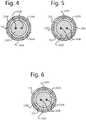
- Figs 4 - 6 show a cross section of the MI-cable.
- the MI-cable comprises an outer metallic jacket 102A, two or more conductors 102B disposed in the outer metallic jacket 102A and Magnesium Oxide insulation 102C.
- the length of the MI-cable depends on the application requirement.
- the outer metallic jacket could be an Inconel sheath or any other metal, e.g. stainless steel or copper, depending on the application requirement.
- the sensor 100 further comprises a sealing flange element 106.
- the sealing flange element is used in conjunction with the mounting nut 108, to secure the sensor in the application.
- the sealing flange element 106 could be a ring-shaped element which is attached to the outer metallic jacket of the MI-cable for example by welding.
- the ring-shaped weld forms a hermetic sealing between the MI-cable and the ring-shaped element.
- the sensor 100 further comprises a tube-like element 110.
- the tube-like element could be an extruded part obtained by an extrusion process.
- the tube-like element is located externally to the outer metallic jacket and surrounds at least a part of the MI-cable 102 between the sealing flange element 106 and the sensing end 102D of the MI-cable.
- the tube-like element could be constructed of any suitable alloy, for example Inconel, stainless steel or copper.
- the tube-like element has an inner diameter such that it fits over the outer metallic jacket leaving a space between outer surface of the MI-cable and the inner surface of the tube-like element.
- a proximal end 110A of the tube-like element 110 is attached to the sealing flange element 106, for example by laser welding.
- the tube-like element 110 is radially crimped such that the crimps align the axis of the tube-like element 110 and the MI-cable 102. In this way, a major part of the inner surface the tube-like element is at a predefined distance from the outer surface of the MI-cable. This distance forms a gap between the MI-cable and the tube-like element. In use, the gap is filled with the fluid whose temperature is measured. In a more expensive embodiment the gap might be filled with any suitable flexible thermal insulating material that resists the high temperature of the fluid to be measured.
- Said distance is preferably chosen such that the combination of heat transfer by 1) conduction through the fluid in the gap, 2) the radiation across the air gap from the tube-like element to the MI-cable is optimal with respect to the diameter of the tube-like element.
- the distance should be small enough to prevent convection and large enough to reduce sufficiently the radiation across the gap.
- the sensor 100 further comprises a rear housing 114 which transitions the electrical signal from the MI-cable to flexible harness 112.
- the present application will focus on the interaction between the MI-cable between the sealing flange element and the sensing element.
- the sensing element 104 is formed by a thermocouple junction (type-N) (not shown).
- the thermocouple junction is obtained by welding the conductors of the MI-cable.
- the sensor has the function of outputting an electrical voltage difference in the conductors depending on the temperature of the junction.
- the junction is protected from the sensed fluid by a protective cap, which is welded to the outer metallic jacket of the MI-cable.
- the function of the tube-like element 110 is as follows. During application of thermal energy to the environment of the sensor, heat must transfer first into the sheath assembly's outer surface.
- the heat at the inner surface may either conduct through the medium in the gap, transfer by radiation across the gap in case of a fluid or conduct across the areas of the crimps that has mechanical contact with the outer metallic jacket of the MI-cable.
- This has the effect of lowering the magnitude of the thermal gradient between the outer jacket 102 and conductors of the MI-cable 102B and thus to lowering the difference in thermal expansion of the outer jacket and conductors of the MI-cable. This lowers the magnitude of stress experienced by the conductors during a thermal cycle, thus improving thermal shock response of the sensor.
- Fig. 2 shows schematically a partial cross sectional view of the first embodiment. In this embodiment only a part of the MI-cable between the sealing flange element 106 and the sensing element 104 is shielded by a heat shield formed by the tube-like element 110. A hotspot region with highest temperature variation in this particular application is indicated with reference numeral 120.
- Figure 2 shows further that the tube-like element 110 comprises three radially crimped regions 130.
- a cross sectional view of the two left sided crimped regions is given in Figure. 4 and a cross sectional view of the crimped region nearest to the sensing element is given in Figure 5 .
- Tests have shown that having two crimped regions at the proximal end of the protection tube around the MI-cable improves the resistance of the combination of sealing element 106 and tube-like element 110 with respect to vibrations.
- radially crimped regions are not present in the hotspot region to reduce thermal transfer.
- Fig. 3 shows schematically a partial cross sectional view of a second embodiment of a temperature sensor.
- This embodiment differs from the embodiment in Figure 2 in that tube-like element 110 extends fully along the length of the MI-cable between the sealing flange element and the sensing element. This is necessary when the hot-spot region 122 is not limited to a relative small part at the length of the MI-cable in contact with the fluid. Furthermore, when the length of the MI-cable inserted in a fluid to be sensed is long and the hotspot region is wide, it might be necessary to have one or more crimped regions between the one or two crimps located at the sealing element side and the crimp located at the sensing element side.
- tube-like element could be deformed by the flow such that the gap width is not the same at all places. Consequently, the heat transfer characteristic from the fluid through the tube-like element and the gap to the MI-cable is not equal around the MI-cable and the MI-cable is heated at one side faster than the opposite side and will bend due to differing thermal expansion.
- the additional crimped regions improve the alignment of the central axis of the tube-like element 110 and the central axis of the MI-cable 102.
- Fig. 4 shows schematically a cross sectional view of a first embodiment of a crimped region.
- the crimped region comprises eight wide dimples 130A.
- This type of crimp has the advantage that it provides strong mechanical fixation between the tube-like element and the metallic jacket, improving stiffness and vibration resistance.
- a disadvantage of this type of crimp is that the heat transfer from the tube-like element in these regions to the MI-cable is very good, i.e.
- Figure 5 shows schematically a cross sectional view of a second embodiment of a crimped region.
- the crimped region comprises four narrow dimples 130A.
- a small part of the inner side of the tube-like element 110 is pressed to the outer surface of the MI-cable.
- the space between the tube-like element 110 and the jacket 102A forms a gap.
- This type of crimp has the advantage that the heat transfer from the tube-like element in this region to the MI-cable is much less than the crimped region shown in Figure 4 , i.e. heat resistance is high.
- FIG. 6 shows schematically a cross sectional view of an alternative embodiment of a crimped region with three dimples.
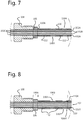
- Figure 7 shows schematically in detail a cross sectional view of the first embodiment in Fig. 2 .
- This figure shows the coupling between the tube-like element 110 and the sealing flange element 106.
- the sealing flange element is a sealing ring which is attached to the metallic jacket 102A of the MI-cable by laser welding.
- An end 110A of the tube-like element is laser welded to the sealing ring.
- the depressions 130A of the two radially crimped regions can be seen.
- the crimped regions are located at the tube-like element.
- Figure 8 shows schematically an alternative embodiment of the sealing element.
- the sealing flange element is made from one piece of metal and comprises a ring section 106A and a tube section 106B.
- the end 110A of the tube-like element is attached to a distal end 106B1 of the tube section 106B.
- the tube section 106B is radially crimped at two locations. Tests have shown that in this embodiment the welded connection between sealing flange element 106 and tube-like element 110 is less sensitive to stress due to vibrations. It might further be possible that the tube section 106B comprises at its distal end one crimped region and the proximal end of the tube-like element 110 comprises a crimped region. In this embodiment the connection between sealing flange element is between said two crimped regions.
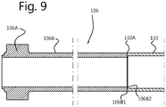
- Figure 9 shows an embodiment of a connection between sealing flange element 106 and tube-like element 110.
- the sealing flange element is one piece comprising the ring section 106A and the tube section 106B.
- An alignment feature 106B2 is provided at a side of the sealing flange element 106 facing the tube-like element 110.
- the alignment feature 106B2 is a triangular projection at the distal end 106B1 of the tube section 106B which is coaxial to the flange element 106.
- the triangular projection fits in the opening at the end 110A of the tube-like element 110.
- the outer diameter of the tube section 106B and tube-like element 110 are similar.
- the inner diameter of the tube 106B section is smaller than the inner diameter of the tube-like element 110.
- the outer diameter of the triangular projection 106B2 matches the inner diameter of the tube-like element 110.
- the triangular projection 106B2 has a width which is preferably equal to the desired gap width between the MI-cable (not shown in figure 9 ) and the tube-like element 110. In this way, a radial crimp of the tube-like element near the proximal end 110A of the tube-like element 110 is not necessary.
- the proximal end 110A of the tube-like element 110 comprises a circular recess to receive the triangular projection 106B2. Furthermore, a radially crimped region at a distal end of the tube section 106B aligns the central axis of the tube section and the MI-cable 102. Consequently the triangular projection 106B2 aligns the central axis of at least the proximal end part of the tube-like element 110.
- a component comprising a mineral insulated cable with an outer metallic jacket, conductors disposed in the outer metallic jacket and Magnesium Oxide insulation.
- a sensing element configured for sensing the physical quantity is already coupled to a sensing end of the Mineral Insulated cable.
- Providing a sealing flange element Attaching the sealing flange element to the mineral insulated cable by a circular welding process.
- a tube-like element is provided. The distal end is inserted in and/or through the tube-like element such that at least a part of the mineral insulated cable between the sealing flange element and the sensing end is positioned in and surrounded by the tube-like element.
- the tube-like element is positioned such that a major part of the inner surface the tube-like element is at a predefined distance from the outer surface of the Mineral Insulated cable to form a gap between mineral insulated cable and the tube-like element.
- a crimped region with three or more dimples might be formed at the tube-like element.
- the depth of the dimples is preferably slightly more than the predefined width of the gap.
- the tube-like element should comprise at least two crimped regions, i.e. at both ends, to obtain a constant gap width between the tube-like element and the MI cable in axial direction.
- the application of the sensing device determines whether this embodiment is suitable.
- the method further comprises: attaching a proximal end of the tube-like element to the sealing flange element.
- the benefits of the present application include a fundamental improvement in thermocouple performance during thermal shock, in increase in product life during thermal cycling, and lower overall conductor temperatures for a given fluid temperature.
- the presented application describes sensors with long probe length or extended temperature operational temperature sensing range which use an MI-cable between sealing flange element and sensing element. These sensors survive in automotive environments for long periods of time.
- thermocouple of type-N as temperature sensing element. It might be clear that the type-N high-temperature thermocouple could be replaced by any other sensing element for sensing a physical characteristic of a fluid having a temperature rapidly varying of a large range to obtain the described advantages. Examples of other sensing elements are not limited to: other types of high-temperature thermocouples, PTC- or NTC-thermistors, and oxygen sensing elements (or lambda sensors).
Landscapes
- Physics & Mathematics (AREA)
- General Physics & Mathematics (AREA)
- Engineering & Computer Science (AREA)
- Chemical & Material Sciences (AREA)
- Chemical Kinetics & Catalysis (AREA)
- Combustion & Propulsion (AREA)
- Mechanical Engineering (AREA)
- General Engineering & Computer Science (AREA)
- Measuring Temperature Or Quantity Of Heat (AREA)
Claims (14)
- Dispositif de détection (100) destiné à détecter une quantité physique d'un fluide, comprenant :- un câble à isolation minérale (102) avec une gaine métallique externe (102A), des conducteurs (102B) entourés par la gaine métallique externe et une isolation en oxyde de magnésium (102C) ;- un élément de détection (104) configuré pour détecter la quantité physique et couplé à une extrémité de détection (102D) du câble à isolation minérale ;- un élément faisant bride d'étanchéité (106) couplé à la gaine métallique externe du câble à isolation minérale ;dans lequel
le dispositif de détection comprend en outre un élément de forme tubulaire (108) entourant au moins une partie du câble à isolation minérale (102) entre l'élément faisant bride d'étanchéité (106) et l'extrémité de détection du câble à isolation minérale, l'élément de détection (104) étant situé à l'extérieur de l'élément de forme tubulaire, et une majeure partie de la surface interne de l'élément de forme tubulaire est à une distance prédéfinie de la surface externe du câble à isolation minérale, formant une lame d'air (112) entre le câble à isolation minérale et l'élément de forme tubulaire, de telle sorte que l'élément de forme tubulaire et la lame d'air fonctionnent comme un isolant thermique entre le fluide et la gaine métallique externe, une petite partie de la surface interne d'une section d'extrémité de l'élément de forme tubulaire la plus proche de l'extrémité de détection du câble à isolation minérale étant comprimée par une opération de sertissage radial sur la surface externe du câble à isolation minérale au moyen d'au moins trois empreintes (130A). - Dispositif de détection selon la revendication 1, dans lequel une extrémité proximale (110A) de l'élément de forme tubulaire est fixée à l'élément faisant bride d'étanchéité.
- Dispositif de détection selon l'une quelconque des revendications 1 - 2, dans lequel l'élément de forme tubulaire est soudé à l'élément faisant bride d'étanchéité.
- Dispositif de détection selon l'une quelconque des revendications 1 - 3, dans lequel l'élément de forme tubulaire comprend au moins une autre région sertie radialement (130) pour aligner le câble à isolation minérale dans l'élément de forme tubulaire.
- Dispositif de détection selon la revendication 4, dans lequel une région sertie radialement (130) de l'élément de forme tubulaire est située dans une section d'extrémité distale (110B) de l'élément de forme tubulaire.
- Dispositif de détection selon l'une quelconque des revendications 4 - 5 dans lequel une région sertie radialement comprend au moins trois empreintes (130A) situées à égale distance les unes des autres.
- Dispositif de détection selon l'une quelconque des revendications 1 - 6, dans lequel l'élément faisant bride d'étanchéité comprend une section annulaire (106A) et une section tubulaire (106B), l'élément de forme tubulaire étant fixé à une extrémité distale de la section tubulaire.
- Dispositif de détection selon la revendication 7, dans lequel l'extrémité distale de la section tubulaire de l'élément faisant bride d'étanchéité comprend un élément d'alignement configuré pour aligner un axe de corps de l'élément faisant bride étanchéité et un axe de corps de l'élément de forme tubulaire.
- Dispositif de détection selon l'une quelconque des revendications 7 - 8, dans lequel la section tubulaire de l'élément faisant bride d'étanchéité comprend au moins une région sertie radialement.
- Dispositif de détection selon la revendication 9, dans lequel une région sertie radialement de la section tubulaire est située dans une section d'extrémité distale de la section tubulaire.
- Dispositif de détection selon l'une quelconque des revendications 1 - 10, dans lequel l'élément de détection est configuré pour détecter la température.
- Procédé d'assemblage d'un dispositif de détection destiné à détecter une quantité physique d'un fluide, le dispositif de détection comprenant les éléments techniques selon l'une quelconque des revendications 1- 11, le procédé comprenant les étapes suivantes :- obtention d'un composant comprenant un câble à isolation minérale avec une gaine métallique externe, des conducteurs entourés par la gaine métallique externe, une isolation en oxyde de magnésium, et un élément de détection configuré pour détecter la quantité physique et couplé à une extrémité de détection du câble à isolation minérale ;- obtention d'un élément faisant bride d'étanchéité ; et- fixation de l'élément faisant bride d'étanchéité au câble à isolation minérale,dans lequel
le procédé comprend en outre :- l'obtention d'un élément de forme tubulaire ;- le positionnement d'au moins une partie du câble à isolation minérale entre l'élément faisant bride d'étanchéité et l'élément de détection dans l'élément de forme tubulaire de telle sorte que l'élément de détection soit situé à l'extérieur de l'élément de forme tubulaire et une majeure partie de la surface interne de l'élément de forme tubulaire soit à une distance prédéfinie de la surface externe du câble à isolation minérale, formant une lame d'air entre le câble à isolation minérale et l'élément de forme tubulaire ; et- la compression par une opération de sertissage radial d'une petite partie de la surface interne d'une section d'extrémité de l'élément de forme tubulaire la plus proche de l'extrémité de détection du câble à isolation minérale sur la surface externe du câble à isolation minérale au moyen d'au moins trois empreintes (130A). - Procédé selon la revendication 12, le procédé comprenant en outre l'étape de fixation d'une extrémité proximale de l'élément de forme tubulaire à l'élément faisant bride d'étanchéité.
- Procédé selon l'une quelconque des revendications 12 - 13, comprenant en outre l'étape de sertissage radial de l'élément de forme tubulaire pour aligner le câble à isolation minérale dans l'élément de forme tubulaire.
Applications Claiming Priority (1)
| Application Number | Priority Date | Filing Date | Title |
|---|---|---|---|
| US15/385,376 US10428716B2 (en) | 2016-12-20 | 2016-12-20 | High-temperature exhaust sensor |
Publications (2)
| Publication Number | Publication Date |
|---|---|
| EP3339825A1 EP3339825A1 (fr) | 2018-06-27 |
| EP3339825B1 true EP3339825B1 (fr) | 2021-10-06 |
Family
ID=57909491
Family Applications (1)
| Application Number | Title | Priority Date | Filing Date |
|---|---|---|---|
| EP17153203.9A Active EP3339825B1 (fr) | 2016-12-20 | 2017-01-26 | Capteur d'échappement haute température |
Country Status (5)
| Country | Link |
|---|---|
| US (1) | US10428716B2 (fr) |
| EP (1) | EP3339825B1 (fr) |
| JP (1) | JP2018100965A (fr) |
| KR (1) | KR20180071966A (fr) |
| CN (1) | CN108204863A (fr) |
Families Citing this family (4)
| Publication number | Priority date | Publication date | Assignee | Title |
|---|---|---|---|---|
| JP7021229B2 (ja) * | 2016-12-30 | 2022-02-16 | ローズマウント インコーポレイテッド | 調節可能なばねが装備された温度センサ用アダプタ |
| US10753807B2 (en) * | 2018-01-19 | 2020-08-25 | Te Wire & Cable Llc | Thermocouple termination/closure and method |
| FR3088424B1 (fr) * | 2018-11-08 | 2021-09-24 | Sc2N Sa | Capteur de temperature avec butee anti-rotation |
| CN113916393A (zh) * | 2021-10-22 | 2022-01-11 | 中国原子能科学研究院 | 热电偶护管及快堆中间热交换器 |
Citations (1)
| Publication number | Priority date | Publication date | Assignee | Title |
|---|---|---|---|---|
| US20100322286A1 (en) * | 2007-11-02 | 2010-12-23 | Kozo Toyama | Quick-response thermocouple for high-speed fluid |
Family Cites Families (177)
| Publication number | Priority date | Publication date | Assignee | Title |
|---|---|---|---|---|
| US2820839A (en) * | 1953-07-23 | 1958-01-21 | Gen Motors Corp | Thermocouple |
| US3691842A (en) | 1970-09-08 | 1972-09-19 | Beckman Instruments Inc | Differential pressure transducer |
| GB1461574A (en) | 1973-03-26 | 1977-01-13 | Smiths Industries Ltd | Temperature-sensing probes |
| US4080027A (en) | 1976-07-30 | 1978-03-21 | Gte Sylvania Incorporated | Electrical contact and connector |
| US4131088A (en) | 1976-11-08 | 1978-12-26 | The Bendix Corporation | Multiple function pressure sensor |
| US4274125A (en) | 1979-01-23 | 1981-06-16 | The Bendix Corporation | Temperature compensated capacitance pressure transducer |
| US4347745A (en) | 1980-12-22 | 1982-09-07 | Bourns Instruments, Inc. | Pressure measuring apparatus |
| US4453835A (en) * | 1982-05-03 | 1984-06-12 | Clawson Burrell E | Temperature sensor |
| US4499330A (en) * | 1983-12-23 | 1985-02-12 | General Electric Company | Anti-vibration support for thermocouple tip |
| US4984461A (en) | 1984-03-14 | 1991-01-15 | Alco Standard Corporation | Fluid flow sensor |
| US4716492A (en) | 1986-05-05 | 1987-12-29 | Texas Instruments Incorporated | Pressure sensor with improved capacitive pressure transducer |
| DE3823449A1 (de) | 1988-07-11 | 1990-01-18 | Bosch Gmbh Robert | Messeinrichtung zur erfassung des drucks und der temperatur |
| DE3832568A1 (de) | 1988-09-24 | 1990-03-29 | Philips Patentverwaltung | Schaltungsanordnung zur temperaturkompensation von kapazitiven druck- und differenzdrucksensoren |
| US4875135A (en) | 1988-12-02 | 1989-10-17 | Texas Instruments Incorporated | Pressure sensor |
| US4955380A (en) | 1988-12-15 | 1990-09-11 | Massachusetts Institute Of Technology | Flexible measurement probes |
| US5259248A (en) | 1990-03-19 | 1993-11-09 | Hitachi Ltd. | Integrated multisensor and static and differential pressure transmitter and plant system using the integrated multisensor |
| US5231301A (en) | 1991-10-02 | 1993-07-27 | Lucas Novasensor | Semiconductor sensor with piezoresistors and improved electrostatic structures |
| US5193912A (en) | 1991-11-18 | 1993-03-16 | Saunders Roger I | Probe for sensing and measuring temperature |
| GB2262837A (en) * | 1991-12-10 | 1993-06-30 | Schlumberger Ind Ltd | Thermocouples |
| US5189591A (en) | 1992-06-12 | 1993-02-23 | Allied-Signal Inc. | Aluminosilicate glass pressure transducer |
| JP2546255Y2 (ja) | 1992-07-08 | 1997-08-27 | 矢崎総業株式会社 | 雌型端子金具 |
| EP0616394A1 (fr) | 1993-03-16 | 1994-09-21 | Hewlett-Packard Company | Procédé et dispositif pour la production de circuits électriquement interconnectés |
| EP0616395B1 (fr) | 1993-03-16 | 1997-09-10 | Hewlett-Packard Company | Procédé et dispositif pour la production de circuits électriquement interconnectés |
| US5308249A (en) | 1993-06-16 | 1994-05-03 | The Whitaker Corporation | Backplane connector utilizing flexible film circuitry |
| US5606513A (en) | 1993-09-20 | 1997-02-25 | Rosemount Inc. | Transmitter having input for receiving a process variable from a remote sensor |
| US5443394A (en) | 1994-05-04 | 1995-08-22 | The Whitaker Corporation | Card edge connector having positive lock and extractor |
| JPH08178778A (ja) | 1994-12-27 | 1996-07-12 | Mitsubishi Electric Corp | 半導体圧力検出装置 |
| US5676559A (en) | 1995-07-06 | 1997-10-14 | The Whitaker Corporation | Zero insertion force (ZIF) electrical connector |
| DE19600822A1 (de) * | 1996-01-11 | 1997-07-17 | Basf Ag | Sonde zur Temperaturmessung |
| US5800186A (en) | 1997-03-13 | 1998-09-01 | Framatome Connectors Usa, Inc. | Printed circuit board assembly |
| JP3379747B2 (ja) | 1997-05-20 | 2003-02-24 | 矢崎総業株式会社 | 低挿入力端子 |
| JP3404257B2 (ja) | 1997-07-11 | 2003-05-06 | 三菱電機株式会社 | 圧力センサ装置 |
| US5974893A (en) | 1997-07-24 | 1999-11-02 | Texas Instruments Incorporated | Combined pressure responsive transducer and temperature sensor apparatus |
| FR2775075B1 (fr) | 1998-02-18 | 2000-05-05 | Theobald Sa A | Capteur de pression differentielle |
| US6412977B1 (en) | 1998-04-14 | 2002-07-02 | The Goodyear Tire & Rubber Company | Method for measuring temperature with an integrated circuit device |
| US6308694B1 (en) | 1999-01-11 | 2001-10-30 | Ford Global Technologies, Inc. | Flow measurement and control |
| JP4409114B2 (ja) | 1999-03-12 | 2010-02-03 | 日本発條株式会社 | 導電性接触子アセンブリ |
| JP2001041838A (ja) | 1999-08-03 | 2001-02-16 | Yamatake Corp | 圧力センサおよびその製造方法 |
| US6473711B1 (en) | 1999-08-13 | 2002-10-29 | Rosemount Inc. | Interchangeable differential, absolute and gage type of pressure transmitter |
| JP2001093634A (ja) | 1999-09-21 | 2001-04-06 | Kato Spring Works Co Ltd | 半導体パッケージ用ソケット |
| US6313523B1 (en) | 1999-10-28 | 2001-11-06 | Hewlett-Packard Company | IC die power connection using canted coil spring |
| US6341962B1 (en) | 1999-10-29 | 2002-01-29 | Aries Electronics, Inc. | Solderless grid array connector |
| JP3619413B2 (ja) | 2000-01-18 | 2005-02-09 | 株式会社エンプラス | 電気部品用ソケット |
| DE10031124C2 (de) | 2000-06-30 | 2002-05-16 | Heraeus Electro Nite Int | Sensor zur Temperaturerfassung eines Fluids |
| DE10031120A1 (de) | 2000-06-30 | 2002-01-17 | Grieshaber Vega Kg | Druckmittler |
| US6363922B1 (en) | 2000-10-11 | 2002-04-02 | Detroit Diesel Corp | Exhaust gas recirculation pressure differential sensor error compensation |
| US6625029B2 (en) | 2000-11-06 | 2003-09-23 | Skg Italiana Spa | Sensor unit |
| JP2002170617A (ja) | 2000-12-04 | 2002-06-14 | Yokowo Co Ltd | コイルばねコネクタ |
| US6588931B2 (en) | 2000-12-07 | 2003-07-08 | Delphi Technologies, Inc. | Temperature sensor with flexible circuit substrate |
| US6668632B2 (en) | 2001-03-05 | 2003-12-30 | Delphi Technologies, Inc. | Spark apparatus with pressure signal response amplification |
| JP3788363B2 (ja) | 2001-03-23 | 2006-06-21 | 株式会社デンソー | 温度センサ |
| WO2003008921A1 (fr) | 2001-07-17 | 2003-01-30 | Measurement Specialties, Inc. | Technique d'isolation pour structure de détection de pression |
| JP4721582B2 (ja) | 2001-09-14 | 2011-07-13 | 株式会社センサータ・テクノロジーズジャパン | ソケット |
| JP2003100375A (ja) | 2001-09-26 | 2003-04-04 | Yokowo Co Ltd | スプリングコネクタ |
| JP2003168532A (ja) | 2001-11-29 | 2003-06-13 | Texas Instr Japan Ltd | 半導体装置用ソケットおよび半導体装置のソケットへの取付け方法 |
| JP4138305B2 (ja) | 2001-12-12 | 2008-08-27 | 株式会社エンプラス | 電気部品用ソケット |
| JP2003234203A (ja) | 2002-02-07 | 2003-08-22 | Denso Corp | 温度センサの製造方法 |
| US6701790B2 (en) | 2002-06-13 | 2004-03-09 | Mykrolis Corporation | Temperature regulator for use with a pressure sensing device |
| US6952042B2 (en) | 2002-06-17 | 2005-10-04 | Honeywell International, Inc. | Microelectromechanical device with integrated conductive shield |
| US6857776B2 (en) * | 2002-12-12 | 2005-02-22 | Ametek, Inc. | Connectorized high-temperature thermocouple |
| FI115109B (fi) | 2003-01-22 | 2005-02-28 | Nokia Corp | Tunnistusjärjestely ja tunnistusjärjestelyn käsittävä matkaviestin |
| JP3942176B2 (ja) | 2003-03-17 | 2007-07-11 | 日本特殊陶業株式会社 | 燃焼圧検知機能付きグロープラグ及びその製造方法 |
| JP4041018B2 (ja) | 2003-06-25 | 2008-01-30 | Tdk株式会社 | 温度センサ |
| US6776668B1 (en) | 2003-08-01 | 2004-08-17 | Tyco Electronics Corporation | Low profile coaxial board-to-board connector |
| US7938783B2 (en) | 2003-08-19 | 2011-05-10 | Advanced Monitors Corporation | Medical body core thermometer |
| DE10343521A1 (de) | 2003-09-19 | 2005-04-21 | Beru Ag | Druckmessglühkerze für einen Dieselmotor |
| US6909975B2 (en) | 2003-11-24 | 2005-06-21 | Mks Instruments, Inc. | Integrated absolute and differential pressure transducer |
| JP2005156307A (ja) | 2003-11-25 | 2005-06-16 | Denso Corp | 圧力センサ |
| US6948372B2 (en) | 2004-01-08 | 2005-09-27 | Delphi Technologies, Inc. | Method of connection to a spark plug pressure sensor |
| CN2679408Y (zh) * | 2004-02-24 | 2005-02-16 | 吴村木 | 一种管体连接件 |
| US7021954B2 (en) | 2004-04-16 | 2006-04-04 | Hon Hai Precision Ind. Co., Ltd. | Test connector with metallic stiffener |
| DE102004021041A1 (de) | 2004-04-29 | 2005-11-24 | Robert Bosch Gmbh | Kombinierter Absolutdruck- und Relativdrucksensor |
| JP2005327628A (ja) | 2004-05-14 | 2005-11-24 | Three M Innovative Properties Co | Icソケット |
| US7073375B2 (en) | 2004-07-02 | 2006-07-11 | Honeywell International Inc. | Exhaust back pressure sensor using absolute micromachined pressure sense die |
| US7077008B2 (en) | 2004-07-02 | 2006-07-18 | Honeywell International Inc. | Differential pressure measurement using backside sensing and a single ASIC |
| JP2006078305A (ja) * | 2004-09-09 | 2006-03-23 | Mitsubishi Heavy Ind Ltd | タービン温度測定器および温度測定器 |
| ATE544034T1 (de) | 2004-09-15 | 2012-02-15 | Beru Ag | Druckmessglühkerze für einen dieselmotor |
| DE102004048367B4 (de) | 2004-10-01 | 2010-10-28 | Endress + Hauser Gmbh + Co. Kg | Verfahren zur Befüllung eines Druckmessaufnehmers |
| US7302855B2 (en) | 2004-10-28 | 2007-12-04 | Denso Corporation | Pressure detection device |
| JP4742593B2 (ja) | 2005-01-19 | 2011-08-10 | 株式会社デンソー | 圧力検出装置の製造方法 |
| US7000478B1 (en) | 2005-01-31 | 2006-02-21 | Texas Instruments Incorporated | Combined pressure and temperature transducer |
| US7884432B2 (en) | 2005-03-22 | 2011-02-08 | Ametek, Inc. | Apparatus and methods for shielding integrated circuitry |
| JP2006307834A (ja) | 2005-03-31 | 2006-11-09 | Ngk Spark Plug Co Ltd | 燃焼圧センサおよびそれを備えたグロープラグ |
| FR2884298B1 (fr) | 2005-04-12 | 2007-08-10 | Siemens Vdo Automotive Sas | Bougie de prechauffage a capteur de pression integre |
| JP2006324326A (ja) | 2005-05-17 | 2006-11-30 | Elpida Memory Inc | 半導体装置 |
| JP4421511B2 (ja) | 2005-05-30 | 2010-02-24 | 三菱電機株式会社 | 半導体圧力センサ |
| DE102006022620B4 (de) | 2005-08-19 | 2014-05-22 | Otto Egelhof Gmbh & Co. Kg | Temperatursensor |
| US7316507B2 (en) | 2005-11-03 | 2008-01-08 | Covidien Ag | Electronic thermometer with flex circuit location |
| JP2007132697A (ja) | 2005-11-08 | 2007-05-31 | Denso Corp | 圧力センサ |
| JP4765871B2 (ja) | 2005-11-09 | 2011-09-07 | 株式会社デンソー | 温度センサ |
| US7467891B2 (en) | 2005-11-29 | 2008-12-23 | Sensata Technologies, Inc. | Sensor arrangement for measuring a pressure and a temperature in a fluid |
| DE102005060651A1 (de) | 2005-12-19 | 2007-06-28 | Robert Bosch Gmbh | Kombinierter Druck- und Temperatursensor |
| TWI286383B (en) | 2005-12-23 | 2007-09-01 | Delta Electronics Inc | Semiconductor piezoresistive sensor and operation method thereof |
| US20070193362A1 (en) | 2006-02-06 | 2007-08-23 | Ferguson Stephen K | Fiber optic strain gage |
| US7675409B2 (en) | 2006-02-28 | 2010-03-09 | Paksense, Inc. | Environmental sensing |
| CA2648024C (fr) | 2006-04-03 | 2012-11-13 | Exxonmobil Upstream Research Company | Procede et appareil de blocage du sable et de regulation du debit d'entree au cours d'operations realisees dans un puits de forage |
| JP4867437B2 (ja) | 2006-04-05 | 2012-02-01 | 株式会社デンソー | 温度センサ |
| US7597668B2 (en) | 2006-05-31 | 2009-10-06 | Medisim Ltd. | Non-invasive temperature measurement |
| JP2008064529A (ja) | 2006-09-06 | 2008-03-21 | Denso Corp | 圧力センサ |
| DE102006043324A1 (de) | 2006-09-15 | 2008-03-27 | Robert Bosch Gmbh | Steckfühler zur kombinierten Druck- und Temperaturmessung |
| EP2056087A4 (fr) | 2006-10-02 | 2011-11-30 | Panasonic Elec Works Co Ltd | Capteur de pression |
| JP4867559B2 (ja) | 2006-10-04 | 2012-02-01 | 株式会社デンソー | 圧力センサおよび圧力センサの取付構造 |
| DE102006050451A1 (de) | 2006-10-20 | 2008-04-24 | Endress + Hauser Gmbh + Co. Kg | Druckmessgerät |
| US7814893B2 (en) | 2006-11-17 | 2010-10-19 | Continental Automotive Canada, Inc. | Exhaust gas recirculation system module with integral vacuum |
| US20080219319A1 (en) | 2007-01-05 | 2008-09-11 | Jay Buckalew | Biological parameter monitoring system and method therefor |
| DE102007010403B4 (de) | 2007-03-01 | 2016-02-11 | Heraeus Sensor Technology Gmbh | Temperatursensor und dessen Verwendung in einer Turboladerüberhitzungssicherung |
| JP4858293B2 (ja) | 2007-05-08 | 2012-01-18 | 住友電装株式会社 | 雌端子金具 |
| JP4854612B2 (ja) | 2007-07-09 | 2012-01-18 | センサータ テクノロジーズ マサチューセッツ インコーポレーテッド | ソケット用アダプタ |
| US7651366B2 (en) | 2007-07-16 | 2010-01-26 | Tyco Electronics Corporation | Electrical connector assembly with shorting contacts |
| JP2009074905A (ja) | 2007-09-20 | 2009-04-09 | Denso Corp | エンジン用温度センサ装置 |
| JP2009097926A (ja) | 2007-10-15 | 2009-05-07 | Denso Corp | 圧力センサおよびその取付構造 |
| JP4868413B2 (ja) | 2007-12-04 | 2012-02-01 | センサータ テクノロジーズ インコーポレーテッド | ソケット |
| US7762140B2 (en) | 2008-01-10 | 2010-07-27 | Sensata Technologies, Inc. | Combined fluid pressure and temperature sensor apparatus |
| US20090194831A1 (en) | 2008-02-01 | 2009-08-06 | Custom Sensors & Technologies, Inc. | Integrated cavity in pcb pressure sensor |
| US7578194B1 (en) | 2008-02-11 | 2009-08-25 | Sensata Technologies, Inc. | Differential fluid pressure measurement apparatus |
| US7743662B2 (en) | 2008-02-14 | 2010-06-29 | Kulite Semiconductor Products, Inc. | Low differential pressure transducer |
| US8764464B2 (en) | 2008-02-29 | 2014-07-01 | Fci Americas Technology Llc | Cross talk reduction for high speed electrical connectors |
| TWM344664U (en) | 2008-04-07 | 2008-11-11 | Hon Hai Prec Ind Co Ltd | Electrical contact |
| JP5155246B2 (ja) * | 2008-05-09 | 2013-03-06 | 日本特殊陶業株式会社 | 温度センサ |
| US7591186B1 (en) | 2008-05-15 | 2009-09-22 | Honeywell International Inc. | Conductive seals and method for fabricating the same |
| US7695285B2 (en) | 2008-05-29 | 2010-04-13 | Yokowo Co., Ltd. | Spring connector and connector |
| ITTO20080484A1 (it) | 2008-06-19 | 2009-12-20 | Eltek Spa | Dispositivo sensore di pressione |
| EP2138820B1 (fr) | 2008-06-25 | 2016-09-21 | Sensata Technologies, Inc. | Fiche de mesure de la pression piézorésistante pour un moteur à combustion |
| DE102008002682B4 (de) | 2008-06-26 | 2020-01-30 | Robert Bosch Gmbh | Vorrichtung zur Erfassung des Drucks und der Temperatur in einem Saugrohr einer Brennkraftmaschine |
| CH699078A1 (de) | 2008-07-02 | 2010-01-15 | Kistler Holding Ag | Zündkerze im Grundaufbau mit Drucksensor. |
| US7878074B1 (en) | 2008-07-17 | 2011-02-01 | Strain Measurement Devices, Inc. | Eccentric load sensing device used to sense differential pressures |
| JP5166176B2 (ja) | 2008-09-04 | 2013-03-21 | スリーエム イノベイティブ プロパティズ カンパニー | 電子デバイス用ソケット |
| JP5227729B2 (ja) | 2008-10-07 | 2013-07-03 | アズビル株式会社 | 圧力センサ |
| JP5197297B2 (ja) | 2008-10-17 | 2013-05-15 | スリーエム イノベイティブ プロパティズ カンパニー | Icソケット |
| JP5291585B2 (ja) | 2008-11-07 | 2013-09-18 | 株式会社日本マイクロニクス | 接触子及び電気的接続装置 |
| JP2010118275A (ja) | 2008-11-13 | 2010-05-27 | Yamaichi Electronics Co Ltd | 半導体装置用ソケット |
| CN102282731B (zh) | 2008-11-14 | 2015-10-21 | 莫列斯公司 | 共振修正连接器 |
| DE102009026402B4 (de) * | 2008-11-19 | 2023-11-02 | Endress + Hauser Wetzer Gmbh + Co. Kg | Vorrichtung zur Bestimmung und/oder Überwachung einer Prozessgröße |
| US8217309B2 (en) | 2008-12-15 | 2012-07-10 | Federal-Mogul Italy Srl. | Glow plug with pressure sensing canister |
| JP5187188B2 (ja) | 2008-12-26 | 2013-04-24 | 富士通株式会社 | 半導体集積回路パッケージの設置方法及び電子部品の製造方法 |
| US7976326B2 (en) | 2008-12-31 | 2011-07-12 | Fci Americas Technology Llc | Gender-neutral electrical connector |
| EP2406606B1 (fr) * | 2009-03-13 | 2019-07-31 | Stoneridge, Inc. | Plombage et réduction de tension de détecteur |
| JP2010256187A (ja) | 2009-04-24 | 2010-11-11 | Panasonic Electric Works Co Ltd | 圧力センサ |
| US8215176B2 (en) | 2009-05-27 | 2012-07-10 | Continental Automotive Systems, Inc. | Pressure sensor for harsh media sensing and flexible packaging |
| US20110019714A1 (en) | 2009-07-24 | 2011-01-27 | Perry Loren R | Overmolded temperature sensor and method for fabricating a temperature sensor |
| US8545096B2 (en) * | 2009-08-06 | 2013-10-01 | Ge Infrastructure Sensing, Inc. | Thermal sensor device and method of assembly |
| US8263879B2 (en) | 2009-11-06 | 2012-09-11 | International Business Machines Corporation | Axiocentric scrubbing land grid array contacts and methods for fabrication |
| WO2011094753A2 (fr) | 2010-02-01 | 2011-08-04 | Stoneridge, Inc. | Capteur de température de gaz d'échappement comprenant un manchon de détente des contraintes et/ou antivibration |
| KR101673520B1 (ko) | 2010-03-04 | 2016-11-08 | 삼성전자 주식회사 | 반도체 모듈과 반도체 모듈용 소켓 및 이들의 결합 구조체 |
| CN201667414U (zh) | 2010-04-07 | 2010-12-08 | 富士康(昆山)电脑接插件有限公司 | 电连接器 |
| JP2011220927A (ja) | 2010-04-13 | 2011-11-04 | Yamatake Corp | 圧力センサ |
| US8129624B2 (en) | 2010-05-27 | 2012-03-06 | Sensata Technologies, Inc. | Pressure sensor |
| US8758067B2 (en) | 2010-06-03 | 2014-06-24 | Hsio Technologies, Llc | Selective metalization of electrical connector or socket housing |
| US8234927B2 (en) | 2010-06-08 | 2012-08-07 | Rosemount Inc. | Differential pressure sensor with line pressure measurement |
| US8132464B2 (en) | 2010-07-12 | 2012-03-13 | Rosemount Inc. | Differential pressure transmitter with complimentary dual absolute pressure sensors |
| CN102072782B (zh) * | 2010-08-20 | 2012-08-08 | 丁锡端 | 一种不焊接热电偶或热电阻 |
| WO2012080811A1 (fr) | 2010-12-15 | 2012-06-21 | パナソニック株式会社 | Capteur de pression à semi-conducteurs |
| US8171800B1 (en) | 2011-01-25 | 2012-05-08 | Continental Automotive Systems, Inc. | Differential pressure sensor using dual backside absolute pressure sensing |
| US8523432B2 (en) | 2011-02-04 | 2013-09-03 | Honeywell International Inc. | Thermally isolated temperature sensor |
| WO2012112222A1 (fr) | 2011-02-16 | 2012-08-23 | Arizant Healthcare Inc. | Dispositifs de mesure de température à flux thermique nul avec mesure de température de peau périphérique |
| US8919656B2 (en) | 2011-06-02 | 2014-12-30 | Key Systems, Inc. | Memory button mount |
| US8792753B2 (en) | 2011-06-30 | 2014-07-29 | General Electric Company | Method and system for a fiber optic sensor |
| GB201113807D0 (en) | 2011-08-10 | 2011-09-21 | Isis Innovation | Determining torque in a shaft |
| DE102011085856A1 (de) | 2011-11-07 | 2013-05-08 | Robert Bosch Gmbh | Vorrichtung zur elektrischen Kontaktierung von Elektronikeinheiten |
| US8893562B2 (en) | 2011-11-21 | 2014-11-25 | Methode Electronics, Inc. | System and method for detecting magnetic noise by applying a switching function to magnetic field sensing coils |
| US9846440B2 (en) | 2011-12-15 | 2017-12-19 | Honeywell International Inc. | Valve controller configured to estimate fuel comsumption |
| JP2013159068A (ja) | 2012-02-07 | 2013-08-19 | Brother Industries Ltd | 液滴吐出装置 |
| JP5994286B2 (ja) | 2012-02-28 | 2016-09-21 | 株式会社ジェイテクト | トルク検出装置およびその製造方法 |
| US8373430B1 (en) | 2012-05-06 | 2013-02-12 | Jerzy Roman Sochor | Low inductance contact probe with conductively coupled plungers |
| US9846085B2 (en) | 2012-07-25 | 2017-12-19 | Nxstage Medical, Inc. | Fluid property measurement devices, methods, and systems |
| US9021787B2 (en) | 2012-09-05 | 2015-05-05 | Mi Yan | Fluid delivery apparatus with flow rate sensing means |
| US9379465B2 (en) | 2012-09-14 | 2016-06-28 | Nhk Spring Co., Ltd. | Connection terminal having a press-fitting part inserted into a hollow part of a holding member |
| US9027409B2 (en) | 2012-12-19 | 2015-05-12 | Kulite Semiconductor Products, Inc. | Matching back pressures on differential oil-filled diaphragms |
| TWI633289B (zh) | 2013-03-13 | 2018-08-21 | 不二工機股份有限公司 | 壓力感測器 |
| US9617928B2 (en) | 2013-04-24 | 2017-04-11 | Ford Global Technologies, Llc | Automotive combination sensor |
| DE102013209060A1 (de) | 2013-05-16 | 2014-11-20 | Robert Bosch Gmbh | Vorrichtung zur Erfassung eines Drucks und einer Temperatur eines in einem Kanal strömenden fluiden Mediums |
| US9052011B2 (en) | 2013-05-24 | 2015-06-09 | Cnh Industrial America Llc | Torque sensor system |
| CN103454032A (zh) | 2013-08-16 | 2013-12-18 | 中国电子科技集团公司第四十八研究所 | 一种带热敏电阻的压力敏感芯体 |
| JP6522624B2 (ja) | 2013-09-06 | 2019-05-29 | イリノイ トゥール ワークス インコーポレイティド | 絶対圧差圧圧力トランスデューサー |
| US9312610B2 (en) | 2013-09-06 | 2016-04-12 | Sensata Technologies, Inc. | Stepped spring contact |
| DE102014200093A1 (de) | 2014-01-08 | 2015-07-09 | Robert Bosch Gmbh | Sensor zur Erfassung einer Temperatur und eines Drucks eines fluiden Mediums |
| FR3035500B1 (fr) | 2015-04-21 | 2019-07-19 | Controle Mesure Regulation (Cmr) | Procede de realisation d'une sonde de temperature |
-
2016
- 2016-12-20 US US15/385,376 patent/US10428716B2/en active Active
-
2017
- 2017-01-26 EP EP17153203.9A patent/EP3339825B1/fr active Active
- 2017-12-18 JP JP2017241568A patent/JP2018100965A/ja active Pending
- 2017-12-18 KR KR1020170173918A patent/KR20180071966A/ko not_active Application Discontinuation
- 2017-12-20 CN CN201711382557.6A patent/CN108204863A/zh active Pending
Patent Citations (1)
| Publication number | Priority date | Publication date | Assignee | Title |
|---|---|---|---|---|
| US20100322286A1 (en) * | 2007-11-02 | 2010-12-23 | Kozo Toyama | Quick-response thermocouple for high-speed fluid |
Also Published As
| Publication number | Publication date |
|---|---|
| KR20180071966A (ko) | 2018-06-28 |
| EP3339825A1 (fr) | 2018-06-27 |
| JP2018100965A (ja) | 2018-06-28 |
| CN108204863A (zh) | 2018-06-26 |
| US10428716B2 (en) | 2019-10-01 |
| US20180171856A1 (en) | 2018-06-21 |
Similar Documents
| Publication | Publication Date | Title |
|---|---|---|
| EP3339825B1 (fr) | Capteur d'échappement haute température | |
| US8558538B2 (en) | Blade tip clearance measurement sensor for gas turbine engines | |
| JP5155246B2 (ja) | 温度センサ | |
| US9816879B2 (en) | Temperature sensor | |
| JP5198934B2 (ja) | 温度センサ | |
| EP3112830B1 (fr) | Capteur de température et procédé de production associé | |
| US4971452A (en) | RTD assembly | |
| JP5229355B2 (ja) | 温度センサ | |
| US20130008886A1 (en) | Glow plug | |
| US20150177073A1 (en) | High temperature measuring sensor arrangement | |
| EP2679905B1 (fr) | Bougie de préchauffage à capteur de pression | |
| US7060949B1 (en) | End seal design for temperature sensing probes | |
| JP5618310B1 (ja) | 高温用温度センサ | |
| JP6253616B2 (ja) | 圧力センサ | |
| JP6560562B2 (ja) | 圧力センサ | |
| JP6143926B1 (ja) | 圧力センサ | |
| JP4307209B2 (ja) | 測温素子を有するヒータ | |
| CN110715751B (zh) | 温度传感器 | |
| JP2017015504A (ja) | 温度センサ |
Legal Events
| Date | Code | Title | Description |
|---|---|---|---|
| PUAI | Public reference made under article 153(3) epc to a published international application that has entered the european phase |
Free format text: ORIGINAL CODE: 0009012 |
|
| STAA | Information on the status of an ep patent application or granted ep patent |
Free format text: STATUS: THE APPLICATION HAS BEEN PUBLISHED |
|
| AK | Designated contracting states |
Kind code of ref document: A1 Designated state(s): AL AT BE BG CH CY CZ DE DK EE ES FI FR GB GR HR HU IE IS IT LI LT LU LV MC MK MT NL NO PL PT RO RS SE SI SK SM TR |
|
| AX | Request for extension of the european patent |
Extension state: BA ME |
|
| STAA | Information on the status of an ep patent application or granted ep patent |
Free format text: STATUS: REQUEST FOR EXAMINATION WAS MADE |
|
| 17P | Request for examination filed |
Effective date: 20190102 |
|
| RBV | Designated contracting states (corrected) |
Designated state(s): AL AT BE BG CH CY CZ DE DK EE ES FI FR GB GR HR HU IE IS IT LI LT LU LV MC MK MT NL NO PL PT RO RS SE SI SK SM TR |
|
| STAA | Information on the status of an ep patent application or granted ep patent |
Free format text: STATUS: EXAMINATION IS IN PROGRESS |
|
| 17Q | First examination report despatched |
Effective date: 20191016 |
|
| STAA | Information on the status of an ep patent application or granted ep patent |
Free format text: STATUS: EXAMINATION IS IN PROGRESS |
|
| GRAP | Despatch of communication of intention to grant a patent |
Free format text: ORIGINAL CODE: EPIDOSNIGR1 |
|
| STAA | Information on the status of an ep patent application or granted ep patent |
Free format text: STATUS: GRANT OF PATENT IS INTENDED |
|
| INTG | Intention to grant announced |
Effective date: 20210506 |
|
| GRAS | Grant fee paid |
Free format text: ORIGINAL CODE: EPIDOSNIGR3 |
|
| GRAA | (expected) grant |
Free format text: ORIGINAL CODE: 0009210 |
|
| STAA | Information on the status of an ep patent application or granted ep patent |
Free format text: STATUS: THE PATENT HAS BEEN GRANTED |
|
| AK | Designated contracting states |
Kind code of ref document: B1 Designated state(s): AL AT BE BG CH CY CZ DE DK EE ES FI FR GB GR HR HU IE IS IT LI LT LU LV MC MK MT NL NO PL PT RO RS SE SI SK SM TR |
|
| REG | Reference to a national code |
Ref country code: GB Ref legal event code: FG4D |
|
| REG | Reference to a national code |
Ref country code: CH Ref legal event code: EP Ref country code: AT Ref legal event code: REF Ref document number: 1436598 Country of ref document: AT Kind code of ref document: T Effective date: 20211015 |
|
| REG | Reference to a national code |
Ref country code: IE Ref legal event code: FG4D |
|
| REG | Reference to a national code |
Ref country code: DE Ref legal event code: R096 Ref document number: 602017047027 Country of ref document: DE |
|
| REG | Reference to a national code |
Ref country code: LT Ref legal event code: MG9D |
|
| REG | Reference to a national code |
Ref country code: NL Ref legal event code: MP Effective date: 20211006 |
|
| REG | Reference to a national code |
Ref country code: AT Ref legal event code: MK05 Ref document number: 1436598 Country of ref document: AT Kind code of ref document: T Effective date: 20211006 |
|
| PG25 | Lapsed in a contracting state [announced via postgrant information from national office to epo] |
Ref country code: RS Free format text: LAPSE BECAUSE OF FAILURE TO SUBMIT A TRANSLATION OF THE DESCRIPTION OR TO PAY THE FEE WITHIN THE PRESCRIBED TIME-LIMIT Effective date: 20211006 Ref country code: LT Free format text: LAPSE BECAUSE OF FAILURE TO SUBMIT A TRANSLATION OF THE DESCRIPTION OR TO PAY THE FEE WITHIN THE PRESCRIBED TIME-LIMIT Effective date: 20211006 Ref country code: FI Free format text: LAPSE BECAUSE OF FAILURE TO SUBMIT A TRANSLATION OF THE DESCRIPTION OR TO PAY THE FEE WITHIN THE PRESCRIBED TIME-LIMIT Effective date: 20211006 Ref country code: BG Free format text: LAPSE BECAUSE OF FAILURE TO SUBMIT A TRANSLATION OF THE DESCRIPTION OR TO PAY THE FEE WITHIN THE PRESCRIBED TIME-LIMIT Effective date: 20220106 Ref country code: AT Free format text: LAPSE BECAUSE OF FAILURE TO SUBMIT A TRANSLATION OF THE DESCRIPTION OR TO PAY THE FEE WITHIN THE PRESCRIBED TIME-LIMIT Effective date: 20211006 |
|
| PG25 | Lapsed in a contracting state [announced via postgrant information from national office to epo] |
Ref country code: IS Free format text: LAPSE BECAUSE OF FAILURE TO SUBMIT A TRANSLATION OF THE DESCRIPTION OR TO PAY THE FEE WITHIN THE PRESCRIBED TIME-LIMIT Effective date: 20220206 Ref country code: SE Free format text: LAPSE BECAUSE OF FAILURE TO SUBMIT A TRANSLATION OF THE DESCRIPTION OR TO PAY THE FEE WITHIN THE PRESCRIBED TIME-LIMIT Effective date: 20211006 Ref country code: PT Free format text: LAPSE BECAUSE OF FAILURE TO SUBMIT A TRANSLATION OF THE DESCRIPTION OR TO PAY THE FEE WITHIN THE PRESCRIBED TIME-LIMIT Effective date: 20220207 Ref country code: PL Free format text: LAPSE BECAUSE OF FAILURE TO SUBMIT A TRANSLATION OF THE DESCRIPTION OR TO PAY THE FEE WITHIN THE PRESCRIBED TIME-LIMIT Effective date: 20211006 Ref country code: NO Free format text: LAPSE BECAUSE OF FAILURE TO SUBMIT A TRANSLATION OF THE DESCRIPTION OR TO PAY THE FEE WITHIN THE PRESCRIBED TIME-LIMIT Effective date: 20220106 Ref country code: NL Free format text: LAPSE BECAUSE OF FAILURE TO SUBMIT A TRANSLATION OF THE DESCRIPTION OR TO PAY THE FEE WITHIN THE PRESCRIBED TIME-LIMIT Effective date: 20211006 Ref country code: LV Free format text: LAPSE BECAUSE OF FAILURE TO SUBMIT A TRANSLATION OF THE DESCRIPTION OR TO PAY THE FEE WITHIN THE PRESCRIBED TIME-LIMIT Effective date: 20211006 Ref country code: HR Free format text: LAPSE BECAUSE OF FAILURE TO SUBMIT A TRANSLATION OF THE DESCRIPTION OR TO PAY THE FEE WITHIN THE PRESCRIBED TIME-LIMIT Effective date: 20211006 Ref country code: GR Free format text: LAPSE BECAUSE OF FAILURE TO SUBMIT A TRANSLATION OF THE DESCRIPTION OR TO PAY THE FEE WITHIN THE PRESCRIBED TIME-LIMIT Effective date: 20220107 Ref country code: ES Free format text: LAPSE BECAUSE OF FAILURE TO SUBMIT A TRANSLATION OF THE DESCRIPTION OR TO PAY THE FEE WITHIN THE PRESCRIBED TIME-LIMIT Effective date: 20211006 |
|
| REG | Reference to a national code |
Ref country code: DE Ref legal event code: R097 Ref document number: 602017047027 Country of ref document: DE |
|
| PG25 | Lapsed in a contracting state [announced via postgrant information from national office to epo] |
Ref country code: SM Free format text: LAPSE BECAUSE OF FAILURE TO SUBMIT A TRANSLATION OF THE DESCRIPTION OR TO PAY THE FEE WITHIN THE PRESCRIBED TIME-LIMIT Effective date: 20211006 Ref country code: SK Free format text: LAPSE BECAUSE OF FAILURE TO SUBMIT A TRANSLATION OF THE DESCRIPTION OR TO PAY THE FEE WITHIN THE PRESCRIBED TIME-LIMIT Effective date: 20211006 Ref country code: RO Free format text: LAPSE BECAUSE OF FAILURE TO SUBMIT A TRANSLATION OF THE DESCRIPTION OR TO PAY THE FEE WITHIN THE PRESCRIBED TIME-LIMIT Effective date: 20211006 Ref country code: EE Free format text: LAPSE BECAUSE OF FAILURE TO SUBMIT A TRANSLATION OF THE DESCRIPTION OR TO PAY THE FEE WITHIN THE PRESCRIBED TIME-LIMIT Effective date: 20211006 Ref country code: DK Free format text: LAPSE BECAUSE OF FAILURE TO SUBMIT A TRANSLATION OF THE DESCRIPTION OR TO PAY THE FEE WITHIN THE PRESCRIBED TIME-LIMIT Effective date: 20211006 Ref country code: CZ Free format text: LAPSE BECAUSE OF FAILURE TO SUBMIT A TRANSLATION OF THE DESCRIPTION OR TO PAY THE FEE WITHIN THE PRESCRIBED TIME-LIMIT Effective date: 20211006 |
|
| PLBE | No opposition filed within time limit |
Free format text: ORIGINAL CODE: 0009261 |
|
| STAA | Information on the status of an ep patent application or granted ep patent |
Free format text: STATUS: NO OPPOSITION FILED WITHIN TIME LIMIT |
|
| PG25 | Lapsed in a contracting state [announced via postgrant information from national office to epo] |
Ref country code: MC Free format text: LAPSE BECAUSE OF FAILURE TO SUBMIT A TRANSLATION OF THE DESCRIPTION OR TO PAY THE FEE WITHIN THE PRESCRIBED TIME-LIMIT Effective date: 20211006 |
|
| REG | Reference to a national code |
Ref country code: CH Ref legal event code: PL |
|
| 26N | No opposition filed |
Effective date: 20220707 |
|
| REG | Reference to a national code |
Ref country code: BE Ref legal event code: MM Effective date: 20220131 |
|
| PG25 | Lapsed in a contracting state [announced via postgrant information from national office to epo] |
Ref country code: LU Free format text: LAPSE BECAUSE OF NON-PAYMENT OF DUE FEES Effective date: 20220126 Ref country code: AL Free format text: LAPSE BECAUSE OF FAILURE TO SUBMIT A TRANSLATION OF THE DESCRIPTION OR TO PAY THE FEE WITHIN THE PRESCRIBED TIME-LIMIT Effective date: 20211006 |
|
| PG25 | Lapsed in a contracting state [announced via postgrant information from national office to epo] |
Ref country code: SI Free format text: LAPSE BECAUSE OF FAILURE TO SUBMIT A TRANSLATION OF THE DESCRIPTION OR TO PAY THE FEE WITHIN THE PRESCRIBED TIME-LIMIT Effective date: 20211006 Ref country code: FR Free format text: LAPSE BECAUSE OF NON-PAYMENT OF DUE FEES Effective date: 20220131 Ref country code: BE Free format text: LAPSE BECAUSE OF NON-PAYMENT OF DUE FEES Effective date: 20220131 |
|
| PG25 | Lapsed in a contracting state [announced via postgrant information from national office to epo] |
Ref country code: LI Free format text: LAPSE BECAUSE OF NON-PAYMENT OF DUE FEES Effective date: 20220131 Ref country code: CH Free format text: LAPSE BECAUSE OF NON-PAYMENT OF DUE FEES Effective date: 20220131 |
|
| PG25 | Lapsed in a contracting state [announced via postgrant information from national office to epo] |
Ref country code: IE Free format text: LAPSE BECAUSE OF NON-PAYMENT OF DUE FEES Effective date: 20220126 |
|
| PG25 | Lapsed in a contracting state [announced via postgrant information from national office to epo] |
Ref country code: IT Free format text: LAPSE BECAUSE OF FAILURE TO SUBMIT A TRANSLATION OF THE DESCRIPTION OR TO PAY THE FEE WITHIN THE PRESCRIBED TIME-LIMIT Effective date: 20211006 |
|
| P01 | Opt-out of the competence of the unified patent court (upc) registered |
Effective date: 20230708 |
|
| PG25 | Lapsed in a contracting state [announced via postgrant information from national office to epo] |
Ref country code: HU Free format text: LAPSE BECAUSE OF FAILURE TO SUBMIT A TRANSLATION OF THE DESCRIPTION OR TO PAY THE FEE WITHIN THE PRESCRIBED TIME-LIMIT; INVALID AB INITIO Effective date: 20170126 |
|
| PG25 | Lapsed in a contracting state [announced via postgrant information from national office to epo] |
Ref country code: MK Free format text: LAPSE BECAUSE OF FAILURE TO SUBMIT A TRANSLATION OF THE DESCRIPTION OR TO PAY THE FEE WITHIN THE PRESCRIBED TIME-LIMIT Effective date: 20211006 Ref country code: CY Free format text: LAPSE BECAUSE OF FAILURE TO SUBMIT A TRANSLATION OF THE DESCRIPTION OR TO PAY THE FEE WITHIN THE PRESCRIBED TIME-LIMIT Effective date: 20211006 |
|
| PGFP | Annual fee paid to national office [announced via postgrant information from national office to epo] |
Ref country code: DE Payment date: 20240129 Year of fee payment: 8 Ref country code: GB Payment date: 20240129 Year of fee payment: 8 |