EP3336268B1 - Sealing connector for pipes, such as for outlet pipes - Google Patents
Sealing connector for pipes, such as for outlet pipes Download PDFInfo
- Publication number
- EP3336268B1 EP3336268B1 EP17208074.9A EP17208074A EP3336268B1 EP 3336268 B1 EP3336268 B1 EP 3336268B1 EP 17208074 A EP17208074 A EP 17208074A EP 3336268 B1 EP3336268 B1 EP 3336268B1
- Authority
- EP
- European Patent Office
- Prior art keywords
- sleeve
- pipe
- sealing membrane
- ring parts
- ring
- Prior art date
- Legal status (The legal status is an assumption and is not a legal conclusion. Google has not performed a legal analysis and makes no representation as to the accuracy of the status listed.)
- Active
Links
Images


Classifications
-
- E—FIXED CONSTRUCTIONS
- E03—WATER SUPPLY; SEWERAGE
- E03D—WATER-CLOSETS OR URINALS WITH FLUSHING DEVICES; FLUSHING VALVES THEREFOR
- E03D11/00—Other component parts of water-closets, e.g. noise-reducing means in the flushing system, flushing pipes mounted in the bowl, seals for the bowl outlet, devices preventing overflow of the bowl contents; devices forming a water seal in the bowl after flushing, devices eliminating obstructions in the bowl outlet or preventing backflow of water and excrements from the waterpipe
- E03D11/13—Parts or details of bowls; Special adaptations of pipe joints or couplings for use with bowls, e.g. provisions in bowl construction preventing backflow of waste-water from the bowl in the flushing pipe or cistern, provisions for a secondary flushing, for noise-reducing
- E03D11/16—Means for connecting the bowl to the floor, e.g. to a floor outlet
-
- F—MECHANICAL ENGINEERING; LIGHTING; HEATING; WEAPONS; BLASTING
- F16—ENGINEERING ELEMENTS AND UNITS; GENERAL MEASURES FOR PRODUCING AND MAINTAINING EFFECTIVE FUNCTIONING OF MACHINES OR INSTALLATIONS; THERMAL INSULATION IN GENERAL
- F16L—PIPES; JOINTS OR FITTINGS FOR PIPES; SUPPORTS FOR PIPES, CABLES OR PROTECTIVE TUBING; MEANS FOR THERMAL INSULATION IN GENERAL
- F16L21/00—Joints with sleeve or socket
- F16L21/002—Sleeves or nipples for pipes of the same diameter; Reduction pieces
-
- F—MECHANICAL ENGINEERING; LIGHTING; HEATING; WEAPONS; BLASTING
- F16—ENGINEERING ELEMENTS AND UNITS; GENERAL MEASURES FOR PRODUCING AND MAINTAINING EFFECTIVE FUNCTIONING OF MACHINES OR INSTALLATIONS; THERMAL INSULATION IN GENERAL
- F16L—PIPES; JOINTS OR FITTINGS FOR PIPES; SUPPORTS FOR PIPES, CABLES OR PROTECTIVE TUBING; MEANS FOR THERMAL INSULATION IN GENERAL
- F16L25/00—Construction or details of pipe joints not provided for in, or of interest apart from, groups F16L13/00 - F16L23/00
- F16L25/14—Joints for pipes of different diameters or cross-section
-
- F—MECHANICAL ENGINEERING; LIGHTING; HEATING; WEAPONS; BLASTING
- F16—ENGINEERING ELEMENTS AND UNITS; GENERAL MEASURES FOR PRODUCING AND MAINTAINING EFFECTIVE FUNCTIONING OF MACHINES OR INSTALLATIONS; THERMAL INSULATION IN GENERAL
- F16L—PIPES; JOINTS OR FITTINGS FOR PIPES; SUPPORTS FOR PIPES, CABLES OR PROTECTIVE TUBING; MEANS FOR THERMAL INSULATION IN GENERAL
- F16L41/00—Branching pipes; Joining pipes to walls
- F16L41/08—Joining pipes to walls or pipes, the joined pipe axis being perpendicular to the plane of a wall or to the axis of another pipe
- F16L41/088—Joining pipes to walls or pipes, the joined pipe axis being perpendicular to the plane of a wall or to the axis of another pipe fixed using an elastic grommet between the extremity of the tube and the wall
Definitions
- the invention relates to a device according to the preamble of claim 1.
- Such a device is for example known from US 3349412 and from US 2976543 .
- a flexible sleeve has to be connected in reliable manner to a pipe.
- a rubber sleeve is often used when for instance a pipe of a smaller diameter has to be connected to an existing pipe. This rubber sleeve must be arranged fixedly on the existing pipe in order to prevent the sleeve being pushed away when the pipe of smaller diameter is inserted.
- the rubber sleeves are usually made of a flexible plastic such as EPDM.
- EPDM a flexible plastic
- Adhesive is rapidly affected by the plasticizers in the EPDM, whereby the adhesion deteriorates. It is therefore very difficult to glue an EPDM sleeve directly into an existing housing or to adhere a sealing membrane to a sleeve.
- the use of a sleeve ensures that the sleeve cannot be forgotten during assembly. This is because without a sleeve a drain will lie much too loosely in an outlet pipe. The installer will hereby be alerted to the fact that something is missing. In the case a sealing membrane is formed on the sleeve it is then also easily possible to check whether the sealing membrane has been arranged or not.
- the flexible sleeve has the additional advantage that a seal is hereby obtained over a determined length in the outlet pipe. Possible fouling of the outlet pipe wall or the sleeve will hereby have little effect.
- the form-retaining peripheral flange is formed by a ring vulcanized onto a sealing membrane.
- the vulcanizing results in a firm connection between the sealing membrane and the sleeve.
- the rubber "fuses" and penetrates here into small cavities, such as between the fibres of a sealing membrane provided with a web, whereby capillary action cannot occur. It is optionally also possible to provide the sealing membrane with a web-free zone onto which the rubber can be vulcanized.
- the vulcanized ring can be arranged on one side against the membrane, although the ring can also enclose the edge of the membrane.
- a further advantage is that the vulcanized ring can easily absorb possible stretch in the membrane.
- the vulcanized ring is preferably arranged on either side of the sealing membrane. Arranging the vulcanized ring on either side ensures that the vulcanized rubber penetrates properly into the sealing membrane and moisture can no longer creep past the ring via the sealing membrane through capillary action.
- An additional advantage of a vulcanized ring is that it can more easily be bent against a wall or can follow a recess in the floor. Because the sleeve is pressed into the outlet pipe and is fixed using an outflow of an outlet pipe, the deformed form-retaining ring cannot press the sleeve out of the pipe later.
- the form-retaining peripheral flange is a metal plate.
- the flexible sleeve is preferably vulcanized onto the metal plate.
- a strong connection is realized by vulcanizing the flexible sleeve onto the metal plate.
- the metal plate can then be used as a base surface for adhering for instance a sealing membrane.
- the advantage of this device not according to the invention is that the cement floor with an outlet pipe therein can be made first.
- the slope in the cement floor can be made in simple manner and is not interrupted, as in the prior art, by flanges arranged on the outlet pipe. After the cement floor has been arranged the sleeve can be inserted into the outlet pipe, whereby a good seal is immediately obtained.
- the flexible sleeve has a peripheral edge and the form-retaining peripheral flange is formed by two ring parts which are arranged on each other and between which the peripheral edge of the flexible sleeve is enclosed.
- a cavity with a radially inward directed opening is formed between the ring parts and the peripheral flange of the flexible sleeve is directed radially outward.
- connection between the peripheral flange and the ring parts will be minimally loaded when a pipe part or drain is inserted axially.
- a thickened portion is preferably arranged on the peripheral flange. This thickened portion ensures that after the ring parts have been brought together the flange can no longer be pulled out of the ring parts as a result of a form-fitting seal between the thickened portion and the cavity in the ring parts.
- a downward directed peripheral wall is provided on one of the ring parts for the purpose of coupling to a pipe.
- the device according to the invention can be glued with the downward directed peripheral wall onto an existing pipe.
- a second downward directed peripheral wall is provided concentrically on one of the ring parts.
- the second downward directed peripheral wall makes it possible to arrange a specific embodiment according to the invention on pipes of two different diameters.
- the ring parts are attached to each other by ultrasonic welding.
- the flexible sleeve is preferably of EPDM rubber.
- a flexible layer can be arranged on the two ring parts arranged on each other.
- Figure 1 shows a cross-sectional view of a first embodiment 1 according to the invention.
- Device 1 has a rubber sleeve 2 which is provided on both the outer side and on the inner side with ridges.
- a peripheral flange 3 with a thickened portion 4 is provided on the upper side of sleeve 2.
- Peripheral flange 3 is enclosed between an upper ring part 5 and a lower ring part 6 which are adhered to each other.
- a sealing membrane 7 can for instance be glued onto ring parts 5, 6 in simple manner because a material can be chosen for ring parts 5, 6 which differs from the material of sleeve 2.
- device 1 is inserted into a pipe 8.
- the ridges on the outer side of rubber sleeve 2 provide for a watertight seal between sleeve 2 and pipe 8.
- the ridges on the outer side of rubber sleeve 2 can optionally be omitted if the diameter corresponds closely to the inner diameter of pipe 8.
- Ring parts 5, 6 ensure that sleeve 2 cannot be pushed away into pipe 8 when outflow 9 of a drain 10 is for instance inserted into sleeve 2.
- the advantage of the device according to the invention is that rubber sleeve 2, and thereby sealing membrane 7, cannot be overlooked during installation, since otherwise the drain 10 can only too obviously not be inserted properly into pipe 8.
- Figure 2 shows a device 20 according to the invention.
- a sleeve 21 which has ridges 22 only on the inner side.
- a peripheral flange 23 with a thickened portion 24 is further provided on the upper side.
- Peripheral flange 23 is enclosed and clamped between an upper ring part 25 and a lower ring part 26.
- Lower ring part 26 further has a downward directed peripheral wall 27 with which device 20 can be glued into a pipe 28.
- Figure 3 shows a device 30 according to the invention.
- Device 30 here also has a sleeve 31 provided on the inner side with ridges 32.
- a flange 33 which is enclosed between an upper ring part 34 and a lower ring part 35.
- the lower ring part 35 has two concentrically arranged, downward directed peripheral walls 36, 37.
- peripheral wall 36 engages on the outer side of a pipe 38.
- Sleeve 32 lies here on pipe 38. It is hereby possible to slide into device 30 another pipe with an inner diameter substantially the same as the inner diameter of pipe 38.
- the ridges 32 of sleeve 31 provide for a good seal here.
- More peripheral walls 36, 37 can optionally be provided which can be cut away depending on the diameter of pipe 38.
- Figure 4 shows a cross-sectional view of an embodiment 40 of a device not according to the invention.
- a rubber sleeve 43 is vulcanized onto a metal plate 41 with a central opening 42.
- a sealing membrane 44 can be glued easily to metal plate 41.
- a drain or shower drain 46 can then be inserted with outflow 47 from above into sleeve 43, whereby a good sealing of shower drain 46 on outlet pipe 45 is also realized.
- Metal plate 41 can optionally be bent so that, when a drain is arranged close to a wall, sealing membrane 44 can run upward along the wall.
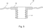
- FIG. 5 shows an embodiment 50 of a device not according to the invention.
- This embodiment 50 has a flexible sleeve 51 with a form-retaining flange 52 thereon which is vulcanized around a sealing membrane 53.
- the vulcanizing thus brings the rubber into direct contact with the sealing membrane such that moisture can no longer pass between the sealing membrane and the rubber. This is a particularly great advantage in the case of a sealing membrane provided with a web layer.
- the rubber sleeve can take a hollow form and be provided on the upper side with small openings in order to nevertheless drain possibly leaking water that gets onto the sealing membrane to the outlet pipe via the small openings and the hollow sleeve.
Landscapes
- Engineering & Computer Science (AREA)
- General Engineering & Computer Science (AREA)
- Mechanical Engineering (AREA)
- Health & Medical Sciences (AREA)
- Life Sciences & Earth Sciences (AREA)
- Hydrology & Water Resources (AREA)
- Public Health (AREA)
- Water Supply & Treatment (AREA)
- Sink And Installation For Waste Water (AREA)
- Joints That Cut Off Fluids, And Hose Joints (AREA)
Priority Applications (1)
| Application Number | Priority Date | Filing Date | Title |
|---|---|---|---|
| PL17208074T PL3336268T3 (pl) | 2013-02-01 | 2014-01-28 | Łącznik uszczelniający do rur, takich jak rury wylotowe |
Applications Claiming Priority (2)
| Application Number | Priority Date | Filing Date | Title |
|---|---|---|---|
| NL2010226A NL2010226C2 (nl) | 2013-02-01 | 2013-02-01 | Inrichting voor aansluiting op een buis, zoals een afvoer. |
| EP14152930.5A EP2762650B1 (en) | 2013-02-01 | 2014-01-28 | Device for connecting a drain to an outlet pipe |
Related Parent Applications (2)
| Application Number | Title | Priority Date | Filing Date |
|---|---|---|---|
| EP14152930.5A Division EP2762650B1 (en) | 2013-02-01 | 2014-01-28 | Device for connecting a drain to an outlet pipe |
| EP14152930.5A Division-Into EP2762650B1 (en) | 2013-02-01 | 2014-01-28 | Device for connecting a drain to an outlet pipe |
Publications (2)
| Publication Number | Publication Date |
|---|---|
| EP3336268A1 EP3336268A1 (en) | 2018-06-20 |
| EP3336268B1 true EP3336268B1 (en) | 2020-01-15 |
Family
ID=48014261
Family Applications (2)
| Application Number | Title | Priority Date | Filing Date |
|---|---|---|---|
| EP17208074.9A Active EP3336268B1 (en) | 2013-02-01 | 2014-01-28 | Sealing connector for pipes, such as for outlet pipes |
| EP14152930.5A Active EP2762650B1 (en) | 2013-02-01 | 2014-01-28 | Device for connecting a drain to an outlet pipe |
Family Applications After (1)
| Application Number | Title | Priority Date | Filing Date |
|---|---|---|---|
| EP14152930.5A Active EP2762650B1 (en) | 2013-02-01 | 2014-01-28 | Device for connecting a drain to an outlet pipe |
Country Status (5)
| Country | Link |
|---|---|
| EP (2) | EP3336268B1 (pl) |
| DK (2) | DK3336268T3 (pl) |
| ES (2) | ES2795062T3 (pl) |
| NL (1) | NL2010226C2 (pl) |
| PL (1) | PL3336268T3 (pl) |
Families Citing this family (7)
| Publication number | Priority date | Publication date | Assignee | Title |
|---|---|---|---|---|
| CA2806916C (en) | 2012-02-20 | 2021-04-06 | Danco, Inc. | Closet collar adaptations |
| CA2849482C (en) | 2013-08-23 | 2021-05-18 | Michael J. Schuster | Seals for closet collars |
| CN105625543A (zh) * | 2016-01-22 | 2016-06-01 | 刘卫东 | 仿生马桶下水 |
| FR3052225B1 (fr) * | 2016-06-06 | 2018-11-16 | Frederic Garate | Piece de raccord, pour le raccordement d'une conduite de descente de gouttiere a une conduite d'evacuation et procede de raccordement correspondant |
| GB2560183B (en) * | 2017-03-02 | 2019-12-18 | Pegler Yorkshire Group Ltd | Sealing pipe liner for connecting metal pipes to plastic pipes |
| CN108343136B (zh) * | 2018-02-01 | 2020-03-20 | 浙江水利水电学院 | 一种用于室内装修的节水马桶 |
| CN111622323A (zh) * | 2020-06-17 | 2020-09-04 | 高文灿 | 马桶排污口密封垫 |
Family Cites Families (15)
| Publication number | Priority date | Publication date | Assignee | Title |
|---|---|---|---|---|
| US961685A (en) * | 1909-09-10 | 1910-06-14 | Joseph J Cosgrove | Water-closet connection. |
| US2976543A (en) * | 1958-01-10 | 1961-03-28 | Debest Mfg Co Inc | Gasket ferrule |
| US3349412A (en) * | 1964-03-19 | 1967-10-31 | Best Mfg Co Inc De | Gasket ferrule |
| DE2325879C2 (de) * | 1973-05-22 | 1975-06-26 | Eddelbuettel & Schneider, 2100 Hamburg | Befestigungsflansch aus Gummi an Gummischläuchen |
| DE7319223U (de) * | 1973-05-22 | 1974-11-07 | Eddelbuettel & Schneider | Befestigungsflansch an Gummischläuchen |
| DE2701320C3 (de) * | 1977-01-14 | 1981-03-12 | Phoenix Ag, 2100 Hamburg | Schlauch und damit festverbundener Flansch |
| JPH04285228A (ja) * | 1991-03-12 | 1992-10-09 | Toyo Tire & Rubber Co Ltd | コンクリートます用可撓接手およびコンクリートます |
| JPH0813594A (ja) * | 1994-06-29 | 1996-01-16 | Inax Corp | 衛生器具の排水管への接続構造 |
| DE29604043U1 (de) * | 1996-03-05 | 1996-04-25 | Dallmer GmbH & Co. KG, 59757 Arnsberg | Dichtungsmuffe für Rohre |
| US9187887B2 (en) * | 2003-02-20 | 2015-11-17 | Coflex S.A. De C.V. | Flange system with modular spacers |
| US20050035558A1 (en) * | 2003-08-12 | 2005-02-17 | Dipzinski Anthony John | Closet flange seal |
| DK176110B1 (da) * | 2005-02-02 | 2006-07-31 | Bluecher Metal As | Gulvaflöb |
| WO2011072025A2 (en) * | 2009-12-08 | 2011-06-16 | Bill Culwell | Water closet flange seal |
| DE202010007693U1 (de) * | 2010-06-08 | 2010-08-26 | Eisenhauer, Michael | Luftabdichtende Steck- und Klebemanschette für Kanäle |
| NL2005289C2 (nl) * | 2010-08-30 | 2012-03-01 | Easy Sanitairy Solutions Bv | Douchevloer afdichtsysteem. |
-
2013
- 2013-02-01 NL NL2010226A patent/NL2010226C2/nl not_active IP Right Cessation
-
2014
- 2014-01-28 EP EP17208074.9A patent/EP3336268B1/en active Active
- 2014-01-28 DK DK17208074.9T patent/DK3336268T3/da active
- 2014-01-28 PL PL17208074T patent/PL3336268T3/pl unknown
- 2014-01-28 DK DK14152930.5T patent/DK2762650T3/da active
- 2014-01-28 ES ES14152930T patent/ES2795062T3/es active Active
- 2014-01-28 ES ES17208074T patent/ES2772721T3/es active Active
- 2014-01-28 EP EP14152930.5A patent/EP2762650B1/en active Active
Non-Patent Citations (1)
| Title |
|---|
| None * |
Also Published As
| Publication number | Publication date |
|---|---|
| ES2772721T3 (es) | 2020-07-08 |
| EP3336268A1 (en) | 2018-06-20 |
| DK2762650T3 (da) | 2020-06-08 |
| EP2762650A1 (en) | 2014-08-06 |
| DK3336268T3 (da) | 2020-02-24 |
| PL3336268T3 (pl) | 2020-06-01 |
| NL2010226C2 (nl) | 2014-08-04 |
| ES2795062T3 (es) | 2020-11-20 |
| EP2762650B1 (en) | 2020-05-06 |
Similar Documents
| Publication | Publication Date | Title |
|---|---|---|
| EP3336268B1 (en) | Sealing connector for pipes, such as for outlet pipes | |
| US9791089B2 (en) | Method and apparatus for repairing a pipe junction | |
| JP5773571B2 (ja) | 基礎部の配管構造及び基礎部の配管工法 | |
| PT2047169E (pt) | Conjunto de tubo e peça de fixação integral em material polímero e método de execução do mesmo | |
| AU2020257546B2 (en) | Drain device having an adapter for connecting to a pipe | |
| JP6044981B2 (ja) | 流水管補修工法 | |
| CA2604601C (en) | Fitting with integral test membrane | |
| WO2013054206A1 (en) | System and methods of flexible and bidirectional sealing device | |
| KR20180132318A (ko) | 파이프 구조체 | |
| KR20160032850A (ko) | 방수용 앵커볼트 | |
| CN104390086B (zh) | 免维护全封闭柔性承插速接管件及其制作方法 | |
| JP5045196B2 (ja) | 排水管接続部材 | |
| CN102418367B (zh) | 用于卫生配件特别是洗脸台配件的定心密封圈 | |
| JP4431240B2 (ja) | シート防水構造物の配管引出部周辺構造 | |
| KR200482505Y1 (ko) | 방수용 앵커볼트 | |
| US20140150531A1 (en) | Selectively sealable pipe stub | |
| KR20110033439A (ko) | 오수받이 | |
| JP2001115536A (ja) | 継ぎ手構造 | |
| JP2002322693A (ja) | 漏水検知機能付き配管構造及び漏水検知具付きソケット等 | |
| JP2007332680A (ja) | 雨水貯留浸透装置用の管接続部構造 | |
| JP3130730U (ja) | 排水管の接続構造 | |
| CN107654786B (zh) | 一种内衬pe薄板水箱防渗漏防污连接管的应用方法 | |
| JP2009074650A (ja) | 閉塞具およびその取付方法 | |
| JP4781130B2 (ja) | 止水サドルおよびそれを用いた更生管路 | |
| JP2001239228A (ja) | 廃棄物処分場の排水・遮水構造及び排水・遮水方法 |
Legal Events
| Date | Code | Title | Description |
|---|---|---|---|
| PUAI | Public reference made under article 153(3) epc to a published international application that has entered the european phase |
Free format text: ORIGINAL CODE: 0009012 |
|
| STAA | Information on the status of an ep patent application or granted ep patent |
Free format text: STATUS: THE APPLICATION HAS BEEN PUBLISHED |
|
| AC | Divisional application: reference to earlier application |
Ref document number: 2762650 Country of ref document: EP Kind code of ref document: P |
|
| AK | Designated contracting states |
Kind code of ref document: A1 Designated state(s): AL AT BE BG CH CY CZ DE DK EE ES FI FR GB GR HR HU IE IS IT LI LT LU LV MC MK MT NL NO PL PT RO RS SE SI SK SM TR |
|
| STAA | Information on the status of an ep patent application or granted ep patent |
Free format text: STATUS: REQUEST FOR EXAMINATION WAS MADE |
|
| 17P | Request for examination filed |
Effective date: 20181217 |
|
| RBV | Designated contracting states (corrected) |
Designated state(s): AL AT BE BG CH CY CZ DE DK EE ES FI FR GB GR HR HU IE IS IT LI LT LU LV MC MK MT NL NO PL PT RO RS SE SI SK SM TR |
|
| GRAP | Despatch of communication of intention to grant a patent |
Free format text: ORIGINAL CODE: EPIDOSNIGR1 |
|
| STAA | Information on the status of an ep patent application or granted ep patent |
Free format text: STATUS: GRANT OF PATENT IS INTENDED |
|
| RIC1 | Information provided on ipc code assigned before grant |
Ipc: E03D 11/14 20060101ALN20190703BHEP Ipc: E03D 11/16 20060101AFI20190703BHEP |
|
| INTG | Intention to grant announced |
Effective date: 20190807 |
|
| GRAS | Grant fee paid |
Free format text: ORIGINAL CODE: EPIDOSNIGR3 |
|
| GRAA | (expected) grant |
Free format text: ORIGINAL CODE: 0009210 |
|
| STAA | Information on the status of an ep patent application or granted ep patent |
Free format text: STATUS: THE PATENT HAS BEEN GRANTED |
|
| AC | Divisional application: reference to earlier application |
Ref document number: 2762650 Country of ref document: EP Kind code of ref document: P |
|
| AK | Designated contracting states |
Kind code of ref document: B1 Designated state(s): AL AT BE BG CH CY CZ DE DK EE ES FI FR GB GR HR HU IE IS IT LI LT LU LV MC MK MT NL NO PL PT RO RS SE SI SK SM TR |
|
| REG | Reference to a national code |
Ref country code: CH Ref legal event code: EP Ref country code: GB Ref legal event code: FG4D |
|
| REG | Reference to a national code |
Ref country code: IE Ref legal event code: FG4D |
|
| REG | Reference to a national code |
Ref country code: DE Ref legal event code: R096 Ref document number: 602014060233 Country of ref document: DE |
|
| REG | Reference to a national code |
Ref country code: AT Ref legal event code: REF Ref document number: 1225266 Country of ref document: AT Kind code of ref document: T Effective date: 20200215 |
|
| REG | Reference to a national code |
Ref country code: DK Ref legal event code: T3 Effective date: 20200218 |
|
| REG | Reference to a national code |
Ref country code: CH Ref legal event code: NV Representative=s name: VALIPAT S.A. C/O BOVARD SA NEUCHATEL, CH |
|
| REG | Reference to a national code |
Ref country code: NL Ref legal event code: FP |
|
| REG | Reference to a national code |
Ref country code: ES Ref legal event code: FG2A Ref document number: 2772721 Country of ref document: ES Kind code of ref document: T3 Effective date: 20200708 |
|
| REG | Reference to a national code |
Ref country code: LT Ref legal event code: MG4D |
|
| PG25 | Lapsed in a contracting state [announced via postgrant information from national office to epo] |
Ref country code: PT Free format text: LAPSE BECAUSE OF FAILURE TO SUBMIT A TRANSLATION OF THE DESCRIPTION OR TO PAY THE FEE WITHIN THE PRESCRIBED TIME-LIMIT Effective date: 20200607 Ref country code: RS Free format text: LAPSE BECAUSE OF FAILURE TO SUBMIT A TRANSLATION OF THE DESCRIPTION OR TO PAY THE FEE WITHIN THE PRESCRIBED TIME-LIMIT Effective date: 20200115 Ref country code: FI Free format text: LAPSE BECAUSE OF FAILURE TO SUBMIT A TRANSLATION OF THE DESCRIPTION OR TO PAY THE FEE WITHIN THE PRESCRIBED TIME-LIMIT Effective date: 20200115 Ref country code: NO Free format text: LAPSE BECAUSE OF FAILURE TO SUBMIT A TRANSLATION OF THE DESCRIPTION OR TO PAY THE FEE WITHIN THE PRESCRIBED TIME-LIMIT Effective date: 20200415 |
|
| PG25 | Lapsed in a contracting state [announced via postgrant information from national office to epo] |
Ref country code: BG Free format text: LAPSE BECAUSE OF FAILURE TO SUBMIT A TRANSLATION OF THE DESCRIPTION OR TO PAY THE FEE WITHIN THE PRESCRIBED TIME-LIMIT Effective date: 20200415 Ref country code: HR Free format text: LAPSE BECAUSE OF FAILURE TO SUBMIT A TRANSLATION OF THE DESCRIPTION OR TO PAY THE FEE WITHIN THE PRESCRIBED TIME-LIMIT Effective date: 20200115 Ref country code: GR Free format text: LAPSE BECAUSE OF FAILURE TO SUBMIT A TRANSLATION OF THE DESCRIPTION OR TO PAY THE FEE WITHIN THE PRESCRIBED TIME-LIMIT Effective date: 20200416 Ref country code: LV Free format text: LAPSE BECAUSE OF FAILURE TO SUBMIT A TRANSLATION OF THE DESCRIPTION OR TO PAY THE FEE WITHIN THE PRESCRIBED TIME-LIMIT Effective date: 20200115 Ref country code: SE Free format text: LAPSE BECAUSE OF FAILURE TO SUBMIT A TRANSLATION OF THE DESCRIPTION OR TO PAY THE FEE WITHIN THE PRESCRIBED TIME-LIMIT Effective date: 20200115 Ref country code: IS Free format text: LAPSE BECAUSE OF FAILURE TO SUBMIT A TRANSLATION OF THE DESCRIPTION OR TO PAY THE FEE WITHIN THE PRESCRIBED TIME-LIMIT Effective date: 20200515 |
|
| REG | Reference to a national code |
Ref country code: DE Ref legal event code: R097 Ref document number: 602014060233 Country of ref document: DE |
|
| PG25 | Lapsed in a contracting state [announced via postgrant information from national office to epo] |
Ref country code: LT Free format text: LAPSE BECAUSE OF FAILURE TO SUBMIT A TRANSLATION OF THE DESCRIPTION OR TO PAY THE FEE WITHIN THE PRESCRIBED TIME-LIMIT Effective date: 20200115 Ref country code: LU Free format text: LAPSE BECAUSE OF NON-PAYMENT OF DUE FEES Effective date: 20200128 Ref country code: EE Free format text: LAPSE BECAUSE OF FAILURE TO SUBMIT A TRANSLATION OF THE DESCRIPTION OR TO PAY THE FEE WITHIN THE PRESCRIBED TIME-LIMIT Effective date: 20200115 Ref country code: SM Free format text: LAPSE BECAUSE OF FAILURE TO SUBMIT A TRANSLATION OF THE DESCRIPTION OR TO PAY THE FEE WITHIN THE PRESCRIBED TIME-LIMIT Effective date: 20200115 Ref country code: SK Free format text: LAPSE BECAUSE OF FAILURE TO SUBMIT A TRANSLATION OF THE DESCRIPTION OR TO PAY THE FEE WITHIN THE PRESCRIBED TIME-LIMIT Effective date: 20200115 Ref country code: RO Free format text: LAPSE BECAUSE OF FAILURE TO SUBMIT A TRANSLATION OF THE DESCRIPTION OR TO PAY THE FEE WITHIN THE PRESCRIBED TIME-LIMIT Effective date: 20200115 Ref country code: MC Free format text: LAPSE BECAUSE OF FAILURE TO SUBMIT A TRANSLATION OF THE DESCRIPTION OR TO PAY THE FEE WITHIN THE PRESCRIBED TIME-LIMIT Effective date: 20200115 |
|
| PLBE | No opposition filed within time limit |
Free format text: ORIGINAL CODE: 0009261 |
|
| STAA | Information on the status of an ep patent application or granted ep patent |
Free format text: STATUS: NO OPPOSITION FILED WITHIN TIME LIMIT |
|
| 26N | No opposition filed |
Effective date: 20201016 |
|
| PG25 | Lapsed in a contracting state [announced via postgrant information from national office to epo] |
Ref country code: IE Free format text: LAPSE BECAUSE OF NON-PAYMENT OF DUE FEES Effective date: 20200128 |
|
| PG25 | Lapsed in a contracting state [announced via postgrant information from national office to epo] |
Ref country code: SI Free format text: LAPSE BECAUSE OF FAILURE TO SUBMIT A TRANSLATION OF THE DESCRIPTION OR TO PAY THE FEE WITHIN THE PRESCRIBED TIME-LIMIT Effective date: 20200115 |
|
| REG | Reference to a national code |
Ref country code: AT Ref legal event code: UEP Ref document number: 1225266 Country of ref document: AT Kind code of ref document: T Effective date: 20200115 |
|
| PG25 | Lapsed in a contracting state [announced via postgrant information from national office to epo] |
Ref country code: TR Free format text: LAPSE BECAUSE OF FAILURE TO SUBMIT A TRANSLATION OF THE DESCRIPTION OR TO PAY THE FEE WITHIN THE PRESCRIBED TIME-LIMIT Effective date: 20200115 Ref country code: MT Free format text: LAPSE BECAUSE OF FAILURE TO SUBMIT A TRANSLATION OF THE DESCRIPTION OR TO PAY THE FEE WITHIN THE PRESCRIBED TIME-LIMIT Effective date: 20200115 Ref country code: CY Free format text: LAPSE BECAUSE OF FAILURE TO SUBMIT A TRANSLATION OF THE DESCRIPTION OR TO PAY THE FEE WITHIN THE PRESCRIBED TIME-LIMIT Effective date: 20200115 |
|
| PG25 | Lapsed in a contracting state [announced via postgrant information from national office to epo] |
Ref country code: MK Free format text: LAPSE BECAUSE OF FAILURE TO SUBMIT A TRANSLATION OF THE DESCRIPTION OR TO PAY THE FEE WITHIN THE PRESCRIBED TIME-LIMIT Effective date: 20200115 Ref country code: AL Free format text: LAPSE BECAUSE OF FAILURE TO SUBMIT A TRANSLATION OF THE DESCRIPTION OR TO PAY THE FEE WITHIN THE PRESCRIBED TIME-LIMIT Effective date: 20200115 |
|
| P01 | Opt-out of the competence of the unified patent court (upc) registered |
Effective date: 20230831 |
|
| PGFP | Annual fee paid to national office [announced via postgrant information from national office to epo] |
Ref country code: GB Payment date: 20240123 Year of fee payment: 11 |
|
| PGFP | Annual fee paid to national office [announced via postgrant information from national office to epo] |
Ref country code: NL Payment date: 20250127 Year of fee payment: 12 |
|
| PGFP | Annual fee paid to national office [announced via postgrant information from national office to epo] |
Ref country code: DE Payment date: 20250129 Year of fee payment: 12 |
|
| PGFP | Annual fee paid to national office [announced via postgrant information from national office to epo] |
Ref country code: DK Payment date: 20250127 Year of fee payment: 12 |
|
| PGFP | Annual fee paid to national office [announced via postgrant information from national office to epo] |
Ref country code: ES Payment date: 20250207 Year of fee payment: 12 |
|
| PGFP | Annual fee paid to national office [announced via postgrant information from national office to epo] |
Ref country code: CH Payment date: 20250201 Year of fee payment: 12 Ref country code: AT Payment date: 20250120 Year of fee payment: 12 Ref country code: BE Payment date: 20250127 Year of fee payment: 12 |
|
| PGFP | Annual fee paid to national office [announced via postgrant information from national office to epo] |
Ref country code: FR Payment date: 20250127 Year of fee payment: 12 Ref country code: PL Payment date: 20250115 Year of fee payment: 12 Ref country code: CZ Payment date: 20250109 Year of fee payment: 12 |
|
| PGFP | Annual fee paid to national office [announced via postgrant information from national office to epo] |
Ref country code: IT Payment date: 20250122 Year of fee payment: 12 |
|
| GBPC | Gb: european patent ceased through non-payment of renewal fee |
Effective date: 20250128 |
|
| PG25 | Lapsed in a contracting state [announced via postgrant information from national office to epo] |
Ref country code: GB Free format text: LAPSE BECAUSE OF NON-PAYMENT OF DUE FEES Effective date: 20250128 |