EP3333477B1 - Linsenkörper, beleuchtungsvorrichtung für fahrzeug - Google Patents
Linsenkörper, beleuchtungsvorrichtung für fahrzeug Download PDFInfo
- Publication number
- EP3333477B1 EP3333477B1 EP18150378.0A EP18150378A EP3333477B1 EP 3333477 B1 EP3333477 B1 EP 3333477B1 EP 18150378 A EP18150378 A EP 18150378A EP 3333477 B1 EP3333477 B1 EP 3333477B1
- Authority
- EP
- European Patent Office
- Prior art keywords
- exit surface
- light
- lens unit
- light source
- lens body
- Prior art date
- Legal status (The legal status is an assumption and is not a legal conclusion. Google has not performed a legal analysis and makes no representation as to the accuracy of the status listed.)
- Active
Links
Images


Classifications
-
- F—MECHANICAL ENGINEERING; LIGHTING; HEATING; WEAPONS; BLASTING
- F21—LIGHTING
- F21S—NON-PORTABLE LIGHTING DEVICES; SYSTEMS THEREOF; VEHICLE LIGHTING DEVICES SPECIALLY ADAPTED FOR VEHICLE EXTERIORS
- F21S41/00—Illuminating devices specially adapted for vehicle exteriors, e.g. headlamps
- F21S41/40—Illuminating devices specially adapted for vehicle exteriors, e.g. headlamps characterised by screens, non-reflecting members, light-shielding members or fixed shades
- F21S41/43—Illuminating devices specially adapted for vehicle exteriors, e.g. headlamps characterised by screens, non-reflecting members, light-shielding members or fixed shades characterised by the shape thereof
-
- B—PERFORMING OPERATIONS; TRANSPORTING
- B60—VEHICLES IN GENERAL
- B60Q—ARRANGEMENT OF SIGNALLING OR LIGHTING DEVICES, THE MOUNTING OR SUPPORTING THEREOF OR CIRCUITS THEREFOR, FOR VEHICLES IN GENERAL
- B60Q1/00—Arrangement of optical signalling or lighting devices, the mounting or supporting thereof or circuits therefor
- B60Q1/02—Arrangement of optical signalling or lighting devices, the mounting or supporting thereof or circuits therefor the devices being primarily intended to illuminate the way ahead or to illuminate other areas of way or environments
- B60Q1/04—Arrangement of optical signalling or lighting devices, the mounting or supporting thereof or circuits therefor the devices being primarily intended to illuminate the way ahead or to illuminate other areas of way or environments the devices being headlights
-
- F—MECHANICAL ENGINEERING; LIGHTING; HEATING; WEAPONS; BLASTING
- F21—LIGHTING
- F21S—NON-PORTABLE LIGHTING DEVICES; SYSTEMS THEREOF; VEHICLE LIGHTING DEVICES SPECIALLY ADAPTED FOR VEHICLE EXTERIORS
- F21S41/00—Illuminating devices specially adapted for vehicle exteriors, e.g. headlamps
- F21S41/10—Illuminating devices specially adapted for vehicle exteriors, e.g. headlamps characterised by the light source
- F21S41/14—Illuminating devices specially adapted for vehicle exteriors, e.g. headlamps characterised by the light source characterised by the type of light source
- F21S41/141—Light emitting diodes [LED]
- F21S41/147—Light emitting diodes [LED] the main emission direction of the LED being angled to the optical axis of the illuminating device
-
- F—MECHANICAL ENGINEERING; LIGHTING; HEATING; WEAPONS; BLASTING
- F21—LIGHTING
- F21S—NON-PORTABLE LIGHTING DEVICES; SYSTEMS THEREOF; VEHICLE LIGHTING DEVICES SPECIALLY ADAPTED FOR VEHICLE EXTERIORS
- F21S41/00—Illuminating devices specially adapted for vehicle exteriors, e.g. headlamps
- F21S41/20—Illuminating devices specially adapted for vehicle exteriors, e.g. headlamps characterised by refractors, transparent cover plates, light guides or filters
- F21S41/25—Projection lenses
- F21S41/26—Elongated lenses
-
- F—MECHANICAL ENGINEERING; LIGHTING; HEATING; WEAPONS; BLASTING
- F21—LIGHTING
- F21S—NON-PORTABLE LIGHTING DEVICES; SYSTEMS THEREOF; VEHICLE LIGHTING DEVICES SPECIALLY ADAPTED FOR VEHICLE EXTERIORS
- F21S41/00—Illuminating devices specially adapted for vehicle exteriors, e.g. headlamps
- F21S41/20—Illuminating devices specially adapted for vehicle exteriors, e.g. headlamps characterised by refractors, transparent cover plates, light guides or filters
- F21S41/25—Projection lenses
- F21S41/27—Thick lenses
-
- F—MECHANICAL ENGINEERING; LIGHTING; HEATING; WEAPONS; BLASTING
- F21—LIGHTING
- F21S—NON-PORTABLE LIGHTING DEVICES; SYSTEMS THEREOF; VEHICLE LIGHTING DEVICES SPECIALLY ADAPTED FOR VEHICLE EXTERIORS
- F21S41/00—Illuminating devices specially adapted for vehicle exteriors, e.g. headlamps
- F21S41/30—Illuminating devices specially adapted for vehicle exteriors, e.g. headlamps characterised by reflectors
- F21S41/32—Optical layout thereof
- F21S41/322—Optical layout thereof the reflector using total internal reflection
-
- F—MECHANICAL ENGINEERING; LIGHTING; HEATING; WEAPONS; BLASTING
- F21—LIGHTING
- F21S—NON-PORTABLE LIGHTING DEVICES; SYSTEMS THEREOF; VEHICLE LIGHTING DEVICES SPECIALLY ADAPTED FOR VEHICLE EXTERIORS
- F21S41/00—Illuminating devices specially adapted for vehicle exteriors, e.g. headlamps
- F21S41/40—Illuminating devices specially adapted for vehicle exteriors, e.g. headlamps characterised by screens, non-reflecting members, light-shielding members or fixed shades
-
- H—ELECTRICITY
- H10—SEMICONDUCTOR DEVICES; ELECTRIC SOLID-STATE DEVICES NOT OTHERWISE PROVIDED FOR
- H10H—INORGANIC LIGHT-EMITTING SEMICONDUCTOR DEVICES HAVING POTENTIAL BARRIERS
- H10H20/00—Individual inorganic light-emitting semiconductor devices having potential barriers, e.g. light-emitting diodes [LED]
- H10H20/80—Constructional details
- H10H20/85—Packages
- H10H20/855—Optical field-shaping means, e.g. lenses
Definitions
- the present invention relates to a lens body and a vehicular lighting fixture.
- a vehicular lamp fitting having a structure of combining a light source and a lens body has been proposed (e.g. JP 2005-228502 A ).
- DE 10 2013 006707 A1 discloses a motor vehicle headlight having at least one first light source and a headlight lens which comprises a blank-molded integrally formed body which is made from a transparent material, and which comprises at least one light tunnel and a light-conducting part having at least one optically effective light exit surface, wherein the light tunnel comprises, an optically effective, light entry surface and merges, while forming a kink, into the light-conducting part for imaging the kink as a light-dark boundary by means of light coupled in or radiated into the light entry surface from the first light source, wherein the light tunnel has a transition region in which the surface delimiting the light tunnel at the top rises in the direction of the light-conducting part.
- the mid-line of the lens is formed by a skew curve arc, and a correcting optical system is provided between the reflector and the lens for obtaining a satisfactory cutoff line, according in particular to the geometry of the entry face and exit face of the lens.
- a lens body combined lens body having an integral appearance linearly extending in a predetermined direction, and a vehicular lamp fitting equipped therewith.
- the present invention has been made in view of these circumstances, providing a lens body as set forth in claim 1 and a vehicular lighting fixture as set forth in claim 7. Preferred embodiments of the present invention may be gathered from the dependent claims.
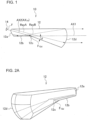
- FIG. 1 is a longitudinal cross-sectional view of the vehicular lamp fitting 10 according to Reference Example 1.
- a dotted line with an arrow at the end indicates an optical path of light from the light source 14 (to be more precise, the reference point F) which entered the lens body 12.
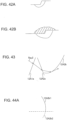
- the entry surface 12a is formed in the rear end of the lens body 12, and is a surface through which the light from the light source 14 (to be more precise, the reference point F in the optical design), which is disposed in the vicinity of the entry surface 12a (see FIG. 4A ), is refracted and enters the lens body 12 (e.g. free-form surface that is convex toward the light source 14), and the surface shape thereof is configured such that the light from the light source 14 (direct light RayA), which entered the lens body 12, is condensed toward the shade 12c in a direction closer to a second reference axis AX2 with respect to at least the vertical direction (see FIG. 4B ).
- the light source 14 includes, for example, a metal substrate (not illustrated), and a semiconductor light emitting element (not illustrated), such as a white LED (Light Emitting Diode) light source (or white LD (Laser Diode) light source) mounted on the surface of the substrate.
- a semiconductor light emitting element such as a white LED (Light Emitting Diode) light source (or white LD (Laser Diode) light source) mounted on the surface of the substrate.
- white LED Light Emitting Diode
- white LD Laser Diode
- the light source 14 may be a light source other than the semiconductor light emitting element, such as a white LED light source (or white LD light source).
- the light source 14 is disposed in the vicinity of the entry surface 12a of the lens body 12 (in the vicinity of the reference point F) in an attitude such that the light emitting surface (not illustrated) thereof faces forward and diagonally downward, in other words, in an attitude such that the optical axis AX 14 of the light source 14 matches the second reference axis AX2.
- the light source 14 may be disposed in the vicinity of the entry surface 12a of the lens body 12 (in the vicinity of the reference point F) in an attitude such that the optical axis AX 14 of the light source 14 does not match the second reference axis AX2 (e.g. in the attitude such that the optical axis AX 14 of the light source 14 is disposed in the horizontal direction).
- I( ⁇ ) denotes the luminous intensity of the light in the direction that is inclined from the optical axis AX 14 of the light source 14 by angle ⁇
- I0 denotes the luminous intensity on the optical axis AX 14 .
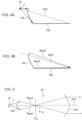
- FIG. 5 is an example of the entry surface 12a (cross-sectional view)
- FIG. 6 is another example of the entry surface 12a (cross-sectional view).
- the surface shape of the entry surface 12a is configured such that the light from the light source 14 which entered the lens body 12 (direct light RayA), is condensed toward the shade 12c in a direction closer to the first reference axis AX1 with respect to the horizontal direction.
- the surface shape of the entry surface 12a may be configured such that the light from the light source 14 which entered the lens body 12 (direct light RayA), becomes parallel with the reference axis AX1 with respect to the horizontal direction.
- the degree of diffusion of the low beam light distribution pattern in the horizontal direction can be freely adjusted by adjusting the surface shape of the entry surface 12a (e.g. curvature of the entry surface 12a in the horizontal direction).
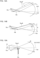
- FIG. 7A and FIG. 7B are diagrams depicting the distance between the entry surface 12a and the light source 14.
- the light source image becomes smaller compared with the case of increasing the distance between the entry surface 12a and the light source 14 (see FIG. 7A ).
- the maximum luminous intensity of the luminous intensity distribution (and the low beam light distribution pattern) that is formed in the vicinity of the focal point F 12d of the exit surface 12d (lens unit) can be increased even more.
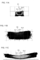
- the low beam light distribution patterns P1 to P3, illustrated in FIG. 11A to FIG. 11C are formed based on this light source image which includes the edges e1, e2 and e3 corresponding to the cut-off lines CL1 to CL3 defined on the upper edge by the shade 12c, hence the low beam light distribution patterns P1 to P3 include the clear cut-off lines CL1, CL2 and CL3 on the upper edges.
- the reflected light RayB' which was internally reflected by the reflection surface 12b, becomes a stray light RayB' which travels in a direction that does not enter the exit surface 12d. As a result, the efficiency drops.
- the second advantage is that the lens body 12 can be downsized compared with the case of disposing the reflection surface 12b in the horizontal direction.
- the height A (height in the vertical direction of the light which exits through the exit surface 12d) indicated in FIG. 14B , decreases 8% compared with the case illustrated in FIG. 14A
- the reflection surface 12b is disposed so as to be inclined with respect to the first reference axis AX1 by 10°
- the height A indicated in FIG. 14B decreases 18.1% compared with the case illustrated in FIG. 14A .
- the advantage is that stray light decreases and efficiency improves compared with the case of disposing the second reference axis AX2 in the horizontal direction and condensing the light from the light source 14 which entered the lens body 12 toward the shade 12c in a direction closer to the second reference axis AX2, at least with respect to the vertical direction.
- the stray light decreases and the efficiency improves compared with the case of disposing the second reference axis AX2 in the horizontal direction and condensing the light from the light source 14 which entered the lens body 12 toward the shade 12c in a direction closer to the second reference axis AX2, at least with respect to the vertical direction.
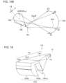
- FIG. 18 is a top view depicting a state where a plurality of vehicular lamp fittings 10 (plurality of lens bodies 12) of Reference Example 1 are disposed on a line.
- the first lens unit 12A1 includes the first entry surface 12a, the reflection surface 12b, the shade 12c, the first exit surface 12A1a and a reference point F that is disposed in the vicinity of the first entry surface 12a in the optical design.
- the second lens unit 12A2 includes the second entry surface 12A2a and the second exit surface 12A2b.
- the first entry surface 12a, the reflection surface 12b, the shade 12c, the first exit surface 12A1a, the second entry surface 12A2a, and the second exit surface 12A2b are disposed in this order along the first reference axis AX1.
- the first reference axis AX passes through a point (e.g. focal point F 12A4 ) in the vicinity of the shade 12c, and extends in the longitudinal direction of the vehicle.
- the second reference axis AX2 passes through the center (to be more precise, the reference point F) of the light source 14 and a point (e.g. focal point F 12A4 ) in the vicinity of the shade 12c, and is inclined forward and diagonally downward with respect to the first reference axis AX1.
- the surface shape of the first entry surface 12a may be configured such that the light from the light source 14, which entered the first lens unit 12A1, becomes parallel with the reference axis AX1 (see FIG. 6 ) with respect to the horizontal direction.
- this lens 12A4 is configured such that light reversely projects the luminous intensity distribution (light source image), which is formed in the vicinity of the focal point F 12A4 of the lens 12A4 by the light beams from the light source 14 which entered the first lens unit 12A1, (in other words, the direct light which travels toward the first exit surface 12A1a and the reflected light which was internally reflected by the reflection surface 12b and travels toward the first exit surface 12A1a, out of the light beams from the light source 14 which entered the first lens unit 12A1), and forms the low beam light distribution pattern P1a, including the cut-off lines CL1 to CL3 defined on an upper edge as illustrated in FIG. 20A on the virtual vertical screen.
- the luminous intensity distribution light source image
- the basic surface shape of the second exit surface 12A2b is as described above, but is actually adjusted as follows, since the extracting angles ⁇ and ⁇ are set for the first exit surface 12A1a and the second entry surface 12A2a.
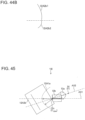
- FIG. 24 is a diagram depicting the normal lines of the first exit surface 12A1a, the second entry surface 12A2a, and the second exit surface 12A2b respectively.
- the normal lines N 12A1a and N 12A2a which pass through the centers of the first exit surface 12A1a and the second entry surface 12A2a, incline with respect to the horizontal line respectively, as illustrated in FIG. 24 .
- the normal line N 12A2b passing through the center of the second exit surface 12A2b, extends in the horizontal direction, the light from the light source 14, which exits through the second exit surface 12A2b, becomes light traveling diagonally upward with respect to the horizontal line, which may cause glare.
- the surface shape of the second exit surface 12A2b is adjusted so that the light from the light source 14, which exits through the second exit surface 12A2b, becomes parallel light with respect to the first reference axis AX1.
- the second exit surface 12A2b is adjusted to the surface shape of which the normal line N 12A2b thereof is inclined forward and diagonally upward, so that the light from the light source 14, which exits through the second exit surface 12A2b, becomes parallel light with respect to the first reference axis AX1.
- This adjustment is performed for matching the focal point F 12A4 of the lens 12A4 constituted by the first exit surface 12A1a and the second lens unit 12A2 (second entry surface 12A2a and second exit surface 12A2b) to a position in the vicinity of the shade 12c.
- the line with an arrow at the end in FIG. 24 indicates the optical path of the light from the light source 14 (to be more precise, the reference point F) which entered the lens body 12A.
- the light from the light source 14 enters the first lens unit 12A1 through the first entry surface 12a of the first lens unit 12A1, and exits through the first exit surface 12A1a of the first lens unit 12A1 after being partially shielded by the shade 12c of the first lens unit 12A1.
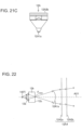
- the light from the light source 14, which exits through the first exit surface 12A1a is condensed in the horizontal direction by a function of the first exit surface 12A1a (see FIG. 22 .
- the light is not condensed or hardly condensed in the vertical direction).
- the light is not condensed, or hardly condensed in the horizontal direction).
- the combined lens body 16 includes a plurality of the lens bodies 12A.
- the combined lens body 16 (a plurality of the lens bodies 12A) is integrally molded by injecting such transparent resins as polycarbonate and acrylic into a die, and cooling and solidifying the resin (injection molding).
- the second exit surface 12A2b of each of the plurality of lens bodies 12A is disposed on a line in the horizontal direction so as to be adjacent to each other, and constitutes a semicircular cylindrical exit surface group having an integral appearance linearly extending in the horizontal direction.
- the combined lens body 16 may be configured by molding a plurality of lens bodies 12 in a physically separated state, and connecting (holding) the lens bodies 12 using a holding member (not illustrated), such as a lens holder.
- the integral appearance linearly extending in the horizontal direction can be implemented because the second exit surface 12A2b, which is the final exit surface, is configured as a semicircular cylindrical surface (semicircular cylindrical refractive surface extending in the horizontal direction).
- a lens body 12A (combined lens body 16) suitable for a vehicular lamp fitting, and a vehicular lamp fitting 10A equipped with the lens body 12A (combined lens body 16), are provided, whereby the light from the light source 14 exited from the second exit surface 12A2b, which is the final exit surface, becomes light parallel with the first reference axis AX1, even though the extracting angles ⁇ and ⁇ are set for the first exit surface 12A1a and the second entry surface 12A2a respectively.
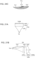
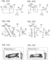
- FIG. 25 is a diagram depicting a lens body 12B, which is a first modification of the lens body 12A of Reference Example 2.
- the extracting angles ⁇ and ⁇ are unnecessary, therefore the adjustment of the second exit surface 12A2b can be omitted.
- the lens body 12C of this modification corresponds to Reference Example 2, where the first exit surface 12A1a and the second exit surface 12A2b are reversed.
- the second exit surface 12A2b of the lens body 12C of this modification is a surface configured to condense the light from the light source 14 which exits through the second exit surface 12A2b in the horizontal direction (corresponding to the second direction of the present invention).
- the second exit surface 12A2b is a semicircular cylindrical surface of which cylindrical axis extends in the vertical direction, which is not in accordance with the claimed present invention, but forms a reference example.
- the focal line of the second exit surface 12A2b extends in the vertical direction in the vicinity of the shade 12c.
- the combined lens body 16C includes a plurality of lens bodies 12C.
- the combined lens body 16C (plurality of lens bodies 12C) is integrally molded by injecting such transparent resins as polycarbonate and acrylic into a die, and cooling and solidifying the resin (injection molding).
- the second exit surface 12A2b of the plurality of lens bodies 12C is disposed on a line in the vertical direction so as to be adjacent to each other, and constitutes a semicircular cylindrical exit surface group having an integral appearance linearly extending in the vertical direction.
- a vehicular lamp fitting 10C having an integral appearance linearly extending in the virtual direction, can be configured.
- the combined lens body 16C may be configured by molding the plurality of lens bodies 12C in a physically separated state, and connecting (holding) the lens bodies 12C using a holding member (not illustrated), such as a lens holder.
- the integral appearance linearly extending in the vertical direction can be implemented because the second exit surface 12A2b, which is the final exit surface, is configured as a semicircular cylindrical surface (semicircular cylindrical refractive surface extending in the vertical direction).
- the low beam light distribution pattern P1a or the like, condensed in the horizontal direction and the vertical direction, can be formed even though the second exit surface 12A2b, which is the final exit surface, is a semicircular cylindrical surface (semicircular cylindrical refractive surface extending in the vertical direction), because condensing light in the vertical direction is mainly performed by the first exit surface 12A1a (semicircular cylindrical refractive surface extending in the horizontal direction) of the first lens unit 12A1, and condensing light in the horizontal direction is mainly performed by the second exit surface 12A2b (semicircular cylindrical refractive surface extending in the vertical direction) of the second lens unit 12A2, which is the final exit surface of the lens body 12A.
- the condensing functions are separated.
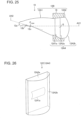
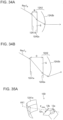
- FIG. 28 is a schematic diagram depicting the direct projection type vehicular lamp fitting 20 to which the concept "condensing functions are separated" is applied.
- the direct projection type vehicular lamp fitting 20 of Reference Example 3 corresponds to a standard direct projection type vehicular lamp fitting, in which a convex lens (convex lens of which final exit surface is a spherical surface) is replaced with the first lens unit 12A1 and the second lens unit 12A2.
- a focal point F 12A5 of a lens 12A5, constituted by the first lens unit 12A1 and the second lens unit 12A2, is set in the vicinity of the upper edge of the shade 22, which is disposed in front of the light source 14 in a state of covering a part of the light source 14 (light emitting surface).
- the first entry surface 12A1b is a plane-shaped (or curved plane-shaped) surface orthogonal to the reference axis AX1.
- the low beam light distribution pattern P1a or the like (corresponding to the predetermined light distribution pattern of the present invention), which includes the cut-off lines CL1 to CL3 defined on the upper edge by the shade 22, as illustrated in FIG. 20A , is formed on a virtual vertical screen.
- a vehicular lamp fitting which forms a high beam light distribution pattern P Hi illustrated in FIG. 29 on a virtual vertical screen, can be configured by omitting the shade 22 in the configuration illustrated in FIG. 28 , and adjusting each surface 12A1a, 12A1b, 12A2a and 12A2b.
- the light from the light source 14 enters the first lens unit 12A1 through the first entry surface 12A1b of the first lens unit 12A1, and exits through the first exit surface 12A1a of the first lens unit 12A1.
- the light from the light source 14 is reflected by the reflector 32, enters the first lens unit 12A1 through the first entry surface 12A1b of the first lens unit 12A1 after being partially shielded by the shade 34, and exits through the first exit surface 12A1a of the first lens unit 12A1.
- the light from the light source 14, which exits through the first exit surface 12A1a is condensed in the horizontal direction by the function of the first exit surface 12A1a (the light is not condensed or hardly condensed in the vertical direction).
- a vehicular head light which formed a high beam light distribution pattern P Hi illustrated in FIG. 29 on a virtual vertical screen, can be configured.
- the light from the light source 14 is reflected by the reflector 32, enters the first lens unit 12A1 through the first entry surface 12A1b of the first lens unit 12A1, and exits through the first exit surface 12A1a of the first lens unit 12A1.
- the light from the light source 14, which exits through the first exit surface 12A1a is condensed in the horizontal direction by the function of the first exit surface 12A1a (the light is not condensed or hardly condensed in the vertical direction).
- the light from the light source 14, which exited through the first exit surface 12A1a passes through the space S, further enters the second lens unit 12A2 through the second entry surface 12A2a of the second lens unit 12A2, then exits through the second exit surface 12A2b of the second lens unit 12A2, and is irradiated forward.
- Embodiment 1 a vehicular lamp fitting 10D, in which a camber angle is added, will be described as Embodiment 1 with reference to the drawings.
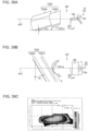
- FIG. 34A is a cross-sectional view (of major optical surfaces only) at the position B in FIG. 32 , and a line with an arrow at the end in FIG. 34A indicates an optical path of the light Ray1B, which enters the first exit surface 12A1a (position B) at a predetermined entry angle.
- FIG. 34B is a cross-sectional view (of major optical surfaces only) at the position C in FIG. 32 , and a line with an arrow at the end in FIG. 34B indicates an optical path of the light Ray1C, which enters the first exit surface 12A1a (position C) at a same entry angle as FIG. 34A .
- the present inventors discovered that this blur is suppressed and the low beam light distribution pattern is generally condensed by adjusting the surface shape of the first exit surface 12A1a (see FIG. 31C ).
- the first exit surface 12A1a of Embodiment 1 is a semicircular cylindrical surface extending in the vertical direction, and the surface shape thereof is adjusted such that the low beam light distribution pattern is generally condensed (see FIG. 31C ).
- This adjustment is for matching the shifted- focal position FB, FC and the like with a position in the vicinity of the shade 12c, and is performed using a predetermined simulation software.
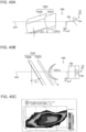
- FIG. 35A is a perspective view (of major optical surfaces only) of the vehicular lamp fitting 10D of Embodiment 1
- FIG. 35B is a comparative example, that is, a perspective view (of major optical surfaces only) of the vehicular lamp fitting 10A of Reference Example 2.
- the first exit surface 12A1a of Embodiment 1 adjusted as mentioned above, becomes non-symmetric-shaped with respect to the reference axis AX1.
- the vehicular lamp fitting 10D of Embodiment 1 is the same as the vehicular lamp fitting 10A of Reference Example 2, except for the above mentioned aspects.
- the reflection surface 12b and the shade 12c of Reference Example 7 are disposed in an attitude inclined with respect to the horizontal direction by the predetermined angle ⁇ 2 in the opposite direction of the second exit surface 12A2b and the first exit surface 12A1a when viewed from the front, similarly to Reference Example 6.
- second reference axis AX2 is inclined with respect to the first reference axis AX1 when viewed from the top
- Reference Example 9 is not limited to the vehicular lamp fitting 10A (lens body 12A) of Embodiment 1, but can be applied to each modification thereof, the vehicular lamp fittings (lens bodies) of Reference Examples 1 to 4, 6 to 8 and the like.
Landscapes
- Engineering & Computer Science (AREA)
- General Engineering & Computer Science (AREA)
- Physics & Mathematics (AREA)
- Microelectronics & Electronic Packaging (AREA)
- Optics & Photonics (AREA)
- Mechanical Engineering (AREA)
- Non-Portable Lighting Devices Or Systems Thereof (AREA)
Claims (9)
- Linsenkörper (10) für einen Fahrzeugscheinwerfer, der eine erste Linseneinheit (12A1) und eine zweite Linseneinheit (12A2) aufweist, die entlang einer ersten Referenzachse (AX1) angeordnet sind, welche sich bei der Anwendung in der Längsrichtung eines Fahrzeugs erstreckt, und so konfiguriert ist, dass Licht von der Lichtquelle (14), welches in die erste Linseneinheit durch eine erste Eintrittsfläche (12a, 12A1b) der ersten Linseneinheit (12a1) eintritt, durch eine erste Austrittsfläche (12A1a) der ersten Linseneinheit (12A1) austritt, weiter in die zweite Linseneinheit (12A2) durch eine zweite Eintrittsfläche (12A2a) der zweiten Linseneinheit (12A2) eintritt, dann durch eine zweite Austrittsfläche (12A2b) der zweiten Linseneinheit (12A2) austritt und nach vorne gestrahlt wird, um ein vorbestimmtes Lichtverteilungsmuster (P1a, PHi) zu formen,
dadurch gekennzeichnet, dassdie zweite Austrittsfläche (12A2b) eine halbkreisförmige zylindrische Oberfläche ist, wobei sich eine Zylinderachse davon in eine Richtung geneigt (θ1) bezüglich der ersten Referenzachse (AX1) erstreckt, wenn man diese von oben ansieht, undwobei die erste Austrittsfläche (12A1a) eine halbkreisförmige zylindrische Oberfläche ist und die Oberflächenformen der ersten Austrittsfläche (12A1a) und der zweiten Austrittsfläche (12A2b) so eingestellt sind, dass das vorbestimmte Lichtverteilungsmuster (P1a, PHi) im Allgemeinen kondensiert bzw. zusammengeführt ist,wobei das Kondensieren bzw. Zusammenführen von Licht in der horizontalen Richtung hauptsächlich durch die erste Austrittsfläche ausgeführt wird, und wobei das Zusammenführen von Licht in der vertikalen Richtung hauptsächlich durch die zweite Austrittsfläche ausgeführt wird, und/oderwobei die erste Austrittsfläche (12A1a) Licht in einer ersten Richtung kondensiert bzw. zusammenführt, und wobei die zweite Austrittsfläche (12A2b) Licht in einer zweiten Richtung zusammenführt, wobei die ersten und zweiten Richtungen orthogonal sind. - Linsenkörper nach Anspruch 1, wobeidie erste Linseneinheit (12A1) eine Blende (12c) aufweist,das Licht von der ersten Lichtquelle (14) in die erste Linseneinheit (12A1) durch die erste Eintrittsfläche (12a) der ersten Linseneinheit (12A1) eintritt, durch die erste Austrittsfläche (12A1a) der ersten Linseneinheit (12A1) austritt, nachdem es teilweise durch die Blende (12c) der ersten Linseneinheit (12A1) abgeschirmt wurde, so dass das vorbestimmte Lichtverteilungsmuster (P1a, PHi), welches durch den Linsenkörper geformt wird, eine Abschnittslinie aufweist, die an einer oberen Kante der Blende (12c) definiert ist.
- Linsenkörper nach Anspruch 1 oder 2, wobei
die erste Linseneinheit (12A1) eine Reflexionsfläche (12b) aufweist, das Licht von der ersten Lichtquelle (14), welches durch die erste Austrittsfläche (12A1a) der ersten Linseneinheit (12A1) austritt, Licht aufweist, welches von der Reflexionsfläche (12b) reflektiert wurde. - Linsenkörper nach einem der Ansprüche 1 bis 3, wobei die Zylinderachse der ersten Austrittsfläche (12A1a) sich i der vertikalen Richtung erstreckt.
- Linsenkörper nach Anspruch 2, wobeidie Zylinderachse der zweiten Austrittsfläche (12A2b) sich in einer Richtung erstreckt, die in einer Ansicht von vorne bezüglich der horizontalen Richtung um einen vorbestimmten Winkel (θ2) geneigt ist,die Zylinderachse der ersten Austrittsfläche (12A1a) sich in einer Richtung erstreckt, die in einer Ansicht von vorne bezüglich der vertikalen Richtung um den vorbestimmten Winkel (θ2) geneigt ist, unddie Blende (12c) in einer Ausrichtung angeordnet ist, die in einer Ansicht von vorne bezüglich der horizontalen Richtung um den vorbestimmten Winkel (θ2) in der entgegengesetzten Richtung der zweiten Austrittsfläche (12A2b) und der ersten Austrittsfläche (12A1a) geneigt ist.
- Linsenkörper nach Anspruch 2 und 3, wobeidie erste Eintrittsfläche (12a), die Reflexionsfläche (12b), die Blende (12c), die erste Austrittsfläche (12A1a), die zweite Eintrittsfläche (12A2a) und die zweite Austrittsfläche (12A2b) in dieser Reihenfolge entlang der ersten Referenzachse (AX1) angeordnet sind,die erste Eintrittsfläche (12a) eine Oberfläche ist, durch welche Licht von der Lichtquelle (14), die in der Nähe der ersten Eintrittsfläche (12a) angeordnet ist, gebrochen wird und in die erste Linseneinheit (12A1) eintritt, und welche so konfiguriert ist, dass das Licht von der Lichtquelle (14), welches in die erste Linseneinheit (12A1) eingetreten ist, in einer Richtung näher zu einer zweiten Referenzachse (AX2) zumindest in der vertikalen Richtung kondensiert bzw. zusammengeführt wird, wobei die zweite Referenzachse (AX2) durch die Mitte der Lichtquelle (14) und einen Punkt in der Nähe der Blende (12c) verläuft und nach vorne und diagonal nach unten bezüglich der ersten Referenzachse (AX1) geneigt ist, die Reflexionsfläche (12b) sich nach vorne von der unteren Kante der ersten Eintrittsfläche (12A1b) erstreckt, unddie Blende (12c) im vorderen Ende der Reflexionsfläche (12b) geformt ist.
- Fahrzeugbeleuchtungsanordnung, die Folgendes aufweist:
den Linsenkörper nach einem der Ansprüche 1 bis 6 und eine Lichtquelle (14), die in der Nähe der ersten Eintrittsfläche (12a) des Linsenkörpers angeordnet ist. - Fahrzeugbeleuchtungsanordnung nach Anspruch 7, wobei die Lichtquelle (14) eine LED-Lichtquelle ist.
- Fahrzeugbeleuchtungsanordnung, die Folgendes aufweist:- den Linsenkörper nach Anspruch 1 oder Anspruch 4, und- eine Lichtquelle (14),- und eine elliptische Reflexionsfläche (32), wobeidas Licht von der Lichtquelle (14), welches von der elliptischen Reflexionsfläche (32) reflektiert wurde, in die erste Linseneinheit (12A1) durch die erste Eintrittsfläche (12A1b) der ersten Linseneinheit (12A1) eintritt, wobei ein erster Fokuspunkt bzw. Brennpunkt (F1) der elliptischen Reflexionsfläche (32) in der Nähe der Lichtquelle (14) festgelegt ist.
Applications Claiming Priority (7)
| Application Number | Priority Date | Filing Date | Title |
|---|---|---|---|
| JP2014107522A JP6260072B2 (ja) | 2014-05-23 | 2014-05-23 | レンズ体、レンズ結合体及び車両用灯具 |
| JP2014107521A JP6256811B2 (ja) | 2014-05-23 | 2014-05-23 | レンズ体及び車両用灯具 |
| JP2014107523A JP6260073B2 (ja) | 2014-05-23 | 2014-05-23 | レンズ体、レンズ結合体及び車両用灯具 |
| JP2014122058A JP6288563B2 (ja) | 2014-06-13 | 2014-06-13 | レンズ体 |
| JP2014195033A JP6361971B2 (ja) | 2014-09-25 | 2014-09-25 | レンズ体及び車両用灯具 |
| PCT/JP2015/062374 WO2015178155A1 (ja) | 2014-05-23 | 2015-04-23 | レンズ体、レンズ結合体及び車両用灯具 |
| EP15796951.0A EP3150905B1 (de) | 2014-05-23 | 2015-04-23 | Linsenkörper, kombinierter linsenkörper und fahrzeuglampenfassung |
Related Parent Applications (2)
| Application Number | Title | Priority Date | Filing Date |
|---|---|---|---|
| EP15796951.0A Division EP3150905B1 (de) | 2014-05-23 | 2015-04-23 | Linsenkörper, kombinierter linsenkörper und fahrzeuglampenfassung |
| EP15796951.0A Division-Into EP3150905B1 (de) | 2014-05-23 | 2015-04-23 | Linsenkörper, kombinierter linsenkörper und fahrzeuglampenfassung |
Publications (2)
| Publication Number | Publication Date |
|---|---|
| EP3333477A1 EP3333477A1 (de) | 2018-06-13 |
| EP3333477B1 true EP3333477B1 (de) | 2024-07-03 |
Family
ID=54553831
Family Applications (2)
| Application Number | Title | Priority Date | Filing Date |
|---|---|---|---|
| EP18150378.0A Active EP3333477B1 (de) | 2014-05-23 | 2015-04-23 | Linsenkörper, beleuchtungsvorrichtung für fahrzeug |
| EP15796951.0A Active EP3150905B1 (de) | 2014-05-23 | 2015-04-23 | Linsenkörper, kombinierter linsenkörper und fahrzeuglampenfassung |
Family Applications After (1)
| Application Number | Title | Priority Date | Filing Date |
|---|---|---|---|
| EP15796951.0A Active EP3150905B1 (de) | 2014-05-23 | 2015-04-23 | Linsenkörper, kombinierter linsenkörper und fahrzeuglampenfassung |
Country Status (3)
| Country | Link |
|---|---|
| US (2) | US10352523B2 (de) |
| EP (2) | EP3333477B1 (de) |
| WO (1) | WO2015178155A1 (de) |
Families Citing this family (37)
| Publication number | Priority date | Publication date | Assignee | Title |
|---|---|---|---|---|
| US10451239B2 (en) | 2014-07-08 | 2019-10-22 | Mitsubishi Electric Corporation | Headlight module and headlight device |
| US9651212B1 (en) * | 2015-12-22 | 2017-05-16 | GM Global Technology Operations LLC | Light assembly |
| CN105546452B (zh) * | 2016-02-01 | 2018-03-23 | 上海小糸车灯有限公司 | 一种车灯全反射近光组合模组 |
| KR20170129445A (ko) * | 2016-05-17 | 2017-11-27 | 현대모비스 주식회사 | 로우빔 구현용 렌즈 조립체 |
| ITUA20164809A1 (it) | 2016-06-30 | 2017-12-30 | Automotive Lighting Italia Spa | Fanale automobilistico comprendente una porzione di emissione luminosa ad effetto opalescente |
| TWI584633B (zh) * | 2016-07-12 | 2017-05-21 | 台達電子工業股份有限公司 | 立體顯示裝置 |
| AT518552B1 (de) * | 2016-08-19 | 2017-11-15 | Zkw Group Gmbh | Beleuchtungseinheit für einen Kraftfahrzeugscheinwerfer zum Erzeugen von zumindest zwei Lichtverteilungen |
| FR3055400B1 (fr) * | 2016-09-01 | 2019-06-28 | Valeo Vision | Module optique pour eclairer des points de portique |
| JP6720809B2 (ja) | 2016-09-29 | 2020-07-08 | オムロン株式会社 | 導光部材、導光部材ユニットおよび照明装置 |
| EP3663637A1 (de) * | 2016-09-30 | 2020-06-10 | H.A. Automotive Systems, Inc. | Kondensator für abblendlichtmodul eines fahrzeugs |
| KR102171391B1 (ko) * | 2017-01-19 | 2020-10-29 | 하스코 비전 테크놀로지 컴퍼니 리미티드 | Adb 기능이 있는 led 광원 하이-로우 빔 일체형 차량용 램프 모듈 |
| JP7154219B2 (ja) * | 2017-03-17 | 2022-10-17 | ルミレッズ ホールディング ベーフェー | 自動車ロービーム用の多焦点コリメートレンズ及びヘッドライトアセンブリ |
| JP7042616B2 (ja) | 2017-12-28 | 2022-03-28 | スタンレー電気株式会社 | 車両用灯具 |
| JP7016257B2 (ja) | 2017-12-28 | 2022-02-21 | スタンレー電気株式会社 | 車両用灯具 |
| JP7042615B2 (ja) * | 2017-12-28 | 2022-03-28 | スタンレー電気株式会社 | 車両用前照灯 |
| JP7093641B2 (ja) | 2018-02-08 | 2022-06-30 | スタンレー電気株式会社 | 車両用灯具 |
| WO2019154139A1 (en) * | 2018-02-08 | 2019-08-15 | Jiaxing Super Lighting Electric Appliance Co., Ltd | Led lamp |
| US11143394B2 (en) | 2018-02-08 | 2021-10-12 | Jiaxing Super Lighting Electric Appliance Co., Ltd | LED lamp |
| US11226078B2 (en) | 2018-04-23 | 2022-01-18 | Stanley Electric Co., Ltd. | Vehicular lamp fitting |
| JP7211655B2 (ja) * | 2018-06-04 | 2023-01-24 | スタンレー電気株式会社 | 車両用灯具 |
| FR3084755B1 (fr) | 2018-08-02 | 2020-12-18 | Valeo Vision | Piece optique comprenant un bloc avec un dioptre formant plieuse pour deux faisceaux |
| CN109140377B (zh) * | 2018-08-03 | 2020-11-24 | 常熟理工学院 | 一种汽车前照灯单元 |
| JP7218041B2 (ja) * | 2019-05-21 | 2023-02-06 | 市光工業株式会社 | 車両用導光体及び車両用灯具ユニット |
| CN210219602U (zh) * | 2019-06-05 | 2020-03-31 | 华域视觉科技(上海)有限公司 | 一种车灯光学元件、车灯模组及车辆 |
| US10753562B1 (en) * | 2019-06-09 | 2020-08-25 | Hossein ALISAFAEE | Lightguide headlamp |
| FR3097979B1 (fr) * | 2019-06-28 | 2021-06-11 | Valeo Vision | Pièce optique destinée à fonctionner en réflexion interne totale |
| US10955681B2 (en) * | 2019-07-10 | 2021-03-23 | Abl Ip Holding Llc | Lighting device with miniature illumination light sources and optical lens sheet |
| CN114270097B (zh) | 2019-08-30 | 2024-01-16 | 三菱电机株式会社 | 前照灯模块和前照灯装置 |
| CN210601445U (zh) * | 2019-10-25 | 2020-05-22 | 华域视觉科技(上海)有限公司 | 一种车灯光学元件 |
| CN211694701U (zh) * | 2020-01-20 | 2020-10-16 | 华域视觉科技(上海)有限公司 | 前照灯光学元件、前照灯模组、车灯及车辆 |
| DE202020102825U1 (de) * | 2020-05-18 | 2020-06-19 | Nimbus Group Gmbh | Asymmetrische Linearlinse und zugehörige Linearleuchte |
| US10865956B1 (en) * | 2020-05-28 | 2020-12-15 | T.Y.C. Brother Industrial Co., Ltd. | Vehicle light |
| US20230008568A1 (en) * | 2021-07-09 | 2023-01-12 | Varroc Lighting Systems, s.r.o. | Lighting and/or signaling device for a motor vehicle and a light guide therefor |
| DE102021127813A1 (de) * | 2021-10-26 | 2023-04-27 | HELLA GmbH & Co. KGaA | Scheinwerfer für ein Kraftfahrzeug sowie Erscheinungslichtmodul für einen derartigen Scheinwerfer |
| JP2024041600A (ja) * | 2022-09-14 | 2024-03-27 | 本田技研工業株式会社 | 車両用照明装置 |
| JP7561801B2 (ja) * | 2022-09-16 | 2024-10-04 | 本田技研工業株式会社 | 車両用照明装置 |
| WO2025249547A1 (ja) * | 2024-05-31 | 2025-12-04 | 市光工業株式会社 | 車両用導光体及び車両用灯具 |
Family Cites Families (32)
| Publication number | Priority date | Publication date | Assignee | Title |
|---|---|---|---|---|
| JPH0738283B2 (ja) * | 1988-07-12 | 1995-04-26 | 株式会社小糸製作所 | 自動車用灯具 |
| US5081564A (en) * | 1989-07-11 | 1992-01-14 | Koito Manufacturing Co., Ltd. | Vehicular lighting device |
| JPH0815412A (ja) * | 1994-06-28 | 1996-01-19 | Nikon Corp | ビーム投光用光学系 |
| JPH09102203A (ja) * | 1995-10-06 | 1997-04-15 | Denso Corp | 車両用灯具装置 |
| JP4068387B2 (ja) * | 2002-04-23 | 2008-03-26 | 株式会社小糸製作所 | 光源ユニット |
| JP4037337B2 (ja) | 2003-07-24 | 2008-01-23 | 株式会社小糸製作所 | 灯具ユニットおよび車両用前照灯 |
| JP4339143B2 (ja) * | 2004-02-10 | 2009-10-07 | 株式会社小糸製作所 | 車両用灯具ユニット |
| FR2872257B1 (fr) * | 2004-06-24 | 2006-08-18 | Valeo Vision Sa | Module d'eclairage pour vehicule automobile et projecteur comportant un tel module |
| FR2884899B1 (fr) | 2005-04-21 | 2007-06-15 | Valeo Vision Sa | Module d'eclairage donnant un faisceau lumineux avec coupure pour projecteur de vehicule automobile, et projecteur comprenant un tel module |
| DE102006006635A1 (de) * | 2006-02-14 | 2007-08-16 | Schefenacker Vision Systems Germany Gmbh | Abblendlichtscheinwerfer, der einen kontraststark ausgebildeten Cut-off erzeugt |
| JP2007317596A (ja) | 2006-05-29 | 2007-12-06 | Koito Mfg Co Ltd | 車両用灯具ユニット |
| FR2905448B1 (fr) * | 2006-09-01 | 2015-05-01 | Valeo Vision | Dispositif d'eclairage ou de signalisation d'aspect guide de lumiere haute performance pour vehicule. |
| FR2910592B1 (fr) * | 2006-12-20 | 2012-07-20 | Valeo Vision | Module de projecteur lumineux de vehicule automobile pour un faisceau a coupure |
| JP2009026462A (ja) | 2007-07-17 | 2009-02-05 | Toyoda Gosei Co Ltd | 車両用灯具 |
| JP2009266710A (ja) * | 2008-04-28 | 2009-11-12 | Ichikoh Ind Ltd | 車両用灯具 |
| JP5196314B2 (ja) * | 2008-10-28 | 2013-05-15 | スタンレー電気株式会社 | 車両用灯具、及び、レンズ体 |
| FR2948439B1 (fr) | 2009-07-21 | 2011-08-05 | Valeo Vision | Module d'eclairage pour projecteur de vehicule automobile, et projecteur equipe d'au moins un tel module. |
| JP5445923B2 (ja) | 2009-09-04 | 2014-03-19 | スタンレー電気株式会社 | 車両用灯具 |
| JP5445049B2 (ja) | 2009-11-13 | 2014-03-19 | スタンレー電気株式会社 | 車両用灯具 |
| EP2322848B1 (de) | 2009-11-12 | 2017-09-27 | Stanley Electric Co., Ltd. | Fahrzeuglicht |
| JP2011171083A (ja) * | 2010-02-17 | 2011-09-01 | Stanley Electric Co Ltd | すれ違いビーム用配光パターン左右反転装置 |
| JP5675272B2 (ja) | 2010-10-28 | 2015-02-25 | 株式会社小糸製作所 | 車輌用灯具 |
| WO2012072190A2 (de) * | 2010-12-03 | 2012-06-07 | Docter Optics Gmbh | Optisches bauteil für beleuchtungszwecke |
| WO2013068053A1 (de) * | 2011-11-11 | 2013-05-16 | Docter Optics Gmbh | Scheinwerferlinse für einen fahrzeugscheinwerfer |
| DE102013006707B4 (de) * | 2012-05-26 | 2025-11-27 | Docter Optics Se | Scheinwerferlinse für einen Fahrzeugscheinwerfer |
| US8714793B2 (en) * | 2012-07-10 | 2014-05-06 | Osram Sylvania Inc. | LED headlight with one or more stepped upward-facing reflectors |
| US8733992B2 (en) * | 2012-10-01 | 2014-05-27 | Osram Sylvania, Inc. | LED low profile linear front fog module |
| JP2014075271A (ja) * | 2012-10-04 | 2014-04-24 | Koito Mfg Co Ltd | 車両用灯具 |
| CN105229371B (zh) * | 2013-05-17 | 2018-08-24 | 市光工业株式会社 | 车辆用前照灯 |
| JP6131724B2 (ja) * | 2013-06-11 | 2017-05-24 | スタンレー電気株式会社 | 車両用灯具 |
| US9587795B2 (en) * | 2013-09-17 | 2017-03-07 | Mitsubishi Electric Corporation | Headlight for in-vehicle use |
| DE102014205450A1 (de) * | 2014-03-24 | 2015-09-24 | Osram Gmbh | Lichtquellenanordnung |
-
2015
- 2015-04-23 EP EP18150378.0A patent/EP3333477B1/de active Active
- 2015-04-23 EP EP15796951.0A patent/EP3150905B1/de active Active
- 2015-04-23 WO PCT/JP2015/062374 patent/WO2015178155A1/ja not_active Ceased
-
2016
- 2016-11-21 US US15/357,643 patent/US10352523B2/en active Active
-
2019
- 2019-05-31 US US16/427,886 patent/US11009210B2/en active Active
Also Published As
| Publication number | Publication date |
|---|---|
| EP3333477A1 (de) | 2018-06-13 |
| WO2015178155A1 (ja) | 2015-11-26 |
| US10352523B2 (en) | 2019-07-16 |
| US11009210B2 (en) | 2021-05-18 |
| EP3150905A1 (de) | 2017-04-05 |
| US20190301697A1 (en) | 2019-10-03 |
| US20170211771A1 (en) | 2017-07-27 |
| EP3150905B1 (de) | 2018-09-19 |
| EP3150905A4 (de) | 2017-06-21 |
Similar Documents
| Publication | Publication Date | Title |
|---|---|---|
| EP3333477B1 (de) | Linsenkörper, beleuchtungsvorrichtung für fahrzeug | |
| US9400089B2 (en) | Vehicle lighting unit | |
| CN101285561B (zh) | 车辆用灯具单元 | |
| JP6268476B2 (ja) | レンズ体及び車両用灯具 | |
| CN106662307B (zh) | 一种用于机动车辆的照明模块 | |
| EP2993392A1 (de) | Linsenelement und fahrzeugbeleuchtungseinheit | |
| EP2159479A2 (de) | Fahrzeuglampeneinheit | |
| EP2767750A2 (de) | Fahrzeugscheinwerfer | |
| EP3181992B1 (de) | Beleuchtungsvorrichtung mit einem linsenkörper und beleuchtungswerkzeug für ein fahrzeug | |
| EP3163155A1 (de) | Optisches streulichtverteilungssystem und fahrzeugbeleuchtungsvorrichtung | |
| KR20230056465A (ko) | 차량용 램프 | |
| CN114270097A (zh) | 前照灯模块和前照灯装置 | |
| JP6256811B2 (ja) | レンズ体及び車両用灯具 | |
| EP3561373B1 (de) | Fahrzeuglampenarmatur | |
| CN106764936B (zh) | 透镜体、透镜结合体以及车辆用灯具 | |
| JP6260073B2 (ja) | レンズ体、レンズ結合体及び車両用灯具 | |
| JP6260072B2 (ja) | レンズ体、レンズ結合体及び車両用灯具 | |
| JP6523418B2 (ja) | 車両用前照灯 | |
| JP6288563B2 (ja) | レンズ体 | |
| JP6523417B2 (ja) | 車両用前照灯 | |
| JP6376450B2 (ja) | レンズ体及び車両用灯具 | |
| JP2017084557A (ja) | レンズ体、レンズ結合体及び車両用灯具 | |
| JP6774470B2 (ja) | 車両用前照灯 | |
| JP7028618B2 (ja) | 車両用灯具 | |
| JP2017103200A (ja) | レンズ体、レンズ結合体及び車両用灯具 |
Legal Events
| Date | Code | Title | Description |
|---|---|---|---|
| PUAI | Public reference made under article 153(3) epc to a published international application that has entered the european phase |
Free format text: ORIGINAL CODE: 0009012 |
|
| STAA | Information on the status of an ep patent application or granted ep patent |
Free format text: STATUS: REQUEST FOR EXAMINATION WAS MADE |
|
| 17P | Request for examination filed |
Effective date: 20180104 |
|
| AC | Divisional application: reference to earlier application |
Ref document number: 3150905 Country of ref document: EP Kind code of ref document: P |
|
| AK | Designated contracting states |
Kind code of ref document: A1 Designated state(s): AL AT BE BG CH CY CZ DE DK EE ES FI FR GB GR HR HU IE IS IT LI LT LU LV MC MK MT NL NO PL PT RO RS SE SI SK SM TR |
|
| STAA | Information on the status of an ep patent application or granted ep patent |
Free format text: STATUS: EXAMINATION IS IN PROGRESS |
|
| 17Q | First examination report despatched |
Effective date: 20211025 |
|
| GRAP | Despatch of communication of intention to grant a patent |
Free format text: ORIGINAL CODE: EPIDOSNIGR1 |
|
| STAA | Information on the status of an ep patent application or granted ep patent |
Free format text: STATUS: GRANT OF PATENT IS INTENDED |
|
| INTG | Intention to grant announced |
Effective date: 20240212 |
|
| GRAS | Grant fee paid |
Free format text: ORIGINAL CODE: EPIDOSNIGR3 |
|
| GRAA | (expected) grant |
Free format text: ORIGINAL CODE: 0009210 |
|
| STAA | Information on the status of an ep patent application or granted ep patent |
Free format text: STATUS: THE PATENT HAS BEEN GRANTED |
|
| AC | Divisional application: reference to earlier application |
Ref document number: 3150905 Country of ref document: EP Kind code of ref document: P |
|
| AK | Designated contracting states |
Kind code of ref document: B1 Designated state(s): AL AT BE BG CH CY CZ DE DK EE ES FI FR GB GR HR HU IE IS IT LI LT LU LV MC MK MT NL NO PL PT RO RS SE SI SK SM TR |
|
| REG | Reference to a national code |
Ref country code: CH Ref legal event code: EP |
|
| REG | Reference to a national code |
Ref country code: DE Ref legal event code: R096 Ref document number: 602015089137 Country of ref document: DE |
|
| REG | Reference to a national code |
Ref country code: LT Ref legal event code: MG9D |
|
| REG | Reference to a national code |
Ref country code: NL Ref legal event code: MP Effective date: 20240703 |
|
| PG25 | Lapsed in a contracting state [announced via postgrant information from national office to epo] |
Ref country code: PT Free format text: LAPSE BECAUSE OF FAILURE TO SUBMIT A TRANSLATION OF THE DESCRIPTION OR TO PAY THE FEE WITHIN THE PRESCRIBED TIME-LIMIT Effective date: 20241104 |
|
| REG | Reference to a national code |
Ref country code: AT Ref legal event code: MK05 Ref document number: 1700154 Country of ref document: AT Kind code of ref document: T Effective date: 20240703 |
|
| PG25 | Lapsed in a contracting state [announced via postgrant information from national office to epo] |
Ref country code: NL Free format text: LAPSE BECAUSE OF FAILURE TO SUBMIT A TRANSLATION OF THE DESCRIPTION OR TO PAY THE FEE WITHIN THE PRESCRIBED TIME-LIMIT Effective date: 20240703 |
|
| PG25 | Lapsed in a contracting state [announced via postgrant information from national office to epo] |
Ref country code: PT Free format text: LAPSE BECAUSE OF FAILURE TO SUBMIT A TRANSLATION OF THE DESCRIPTION OR TO PAY THE FEE WITHIN THE PRESCRIBED TIME-LIMIT Effective date: 20241104 Ref country code: NL Free format text: LAPSE BECAUSE OF FAILURE TO SUBMIT A TRANSLATION OF THE DESCRIPTION OR TO PAY THE FEE WITHIN THE PRESCRIBED TIME-LIMIT Effective date: 20240703 |
|
| PG25 | Lapsed in a contracting state [announced via postgrant information from national office to epo] |
Ref country code: NO Free format text: LAPSE BECAUSE OF FAILURE TO SUBMIT A TRANSLATION OF THE DESCRIPTION OR TO PAY THE FEE WITHIN THE PRESCRIBED TIME-LIMIT Effective date: 20241003 |
|
| PG25 | Lapsed in a contracting state [announced via postgrant information from national office to epo] |
Ref country code: FI Free format text: LAPSE BECAUSE OF FAILURE TO SUBMIT A TRANSLATION OF THE DESCRIPTION OR TO PAY THE FEE WITHIN THE PRESCRIBED TIME-LIMIT Effective date: 20240703 Ref country code: GR Free format text: LAPSE BECAUSE OF FAILURE TO SUBMIT A TRANSLATION OF THE DESCRIPTION OR TO PAY THE FEE WITHIN THE PRESCRIBED TIME-LIMIT Effective date: 20241004 Ref country code: PL Free format text: LAPSE BECAUSE OF FAILURE TO SUBMIT A TRANSLATION OF THE DESCRIPTION OR TO PAY THE FEE WITHIN THE PRESCRIBED TIME-LIMIT Effective date: 20240703 |
|
| PG25 | Lapsed in a contracting state [announced via postgrant information from national office to epo] |
Ref country code: BG Free format text: LAPSE BECAUSE OF FAILURE TO SUBMIT A TRANSLATION OF THE DESCRIPTION OR TO PAY THE FEE WITHIN THE PRESCRIBED TIME-LIMIT Effective date: 20240703 |
|
| PG25 | Lapsed in a contracting state [announced via postgrant information from national office to epo] |
Ref country code: LV Free format text: LAPSE BECAUSE OF FAILURE TO SUBMIT A TRANSLATION OF THE DESCRIPTION OR TO PAY THE FEE WITHIN THE PRESCRIBED TIME-LIMIT Effective date: 20240703 |
|
| PG25 | Lapsed in a contracting state [announced via postgrant information from national office to epo] |
Ref country code: IS Free format text: LAPSE BECAUSE OF FAILURE TO SUBMIT A TRANSLATION OF THE DESCRIPTION OR TO PAY THE FEE WITHIN THE PRESCRIBED TIME-LIMIT Effective date: 20241103 Ref country code: AT Free format text: LAPSE BECAUSE OF FAILURE TO SUBMIT A TRANSLATION OF THE DESCRIPTION OR TO PAY THE FEE WITHIN THE PRESCRIBED TIME-LIMIT Effective date: 20240703 |
|
| PG25 | Lapsed in a contracting state [announced via postgrant information from national office to epo] |
Ref country code: CZ Free format text: LAPSE BECAUSE OF FAILURE TO SUBMIT A TRANSLATION OF THE DESCRIPTION OR TO PAY THE FEE WITHIN THE PRESCRIBED TIME-LIMIT Effective date: 20240703 Ref country code: HR Free format text: LAPSE BECAUSE OF FAILURE TO SUBMIT A TRANSLATION OF THE DESCRIPTION OR TO PAY THE FEE WITHIN THE PRESCRIBED TIME-LIMIT Effective date: 20240703 |
|
| PG25 | Lapsed in a contracting state [announced via postgrant information from national office to epo] |
Ref country code: ES Free format text: LAPSE BECAUSE OF FAILURE TO SUBMIT A TRANSLATION OF THE DESCRIPTION OR TO PAY THE FEE WITHIN THE PRESCRIBED TIME-LIMIT Effective date: 20240703 Ref country code: RS Free format text: LAPSE BECAUSE OF FAILURE TO SUBMIT A TRANSLATION OF THE DESCRIPTION OR TO PAY THE FEE WITHIN THE PRESCRIBED TIME-LIMIT Effective date: 20241003 |
|
| PG25 | Lapsed in a contracting state [announced via postgrant information from national office to epo] |
Ref country code: RS Free format text: LAPSE BECAUSE OF FAILURE TO SUBMIT A TRANSLATION OF THE DESCRIPTION OR TO PAY THE FEE WITHIN THE PRESCRIBED TIME-LIMIT Effective date: 20241003 Ref country code: PL Free format text: LAPSE BECAUSE OF FAILURE TO SUBMIT A TRANSLATION OF THE DESCRIPTION OR TO PAY THE FEE WITHIN THE PRESCRIBED TIME-LIMIT Effective date: 20240703 Ref country code: NO Free format text: LAPSE BECAUSE OF FAILURE TO SUBMIT A TRANSLATION OF THE DESCRIPTION OR TO PAY THE FEE WITHIN THE PRESCRIBED TIME-LIMIT Effective date: 20241003 Ref country code: LV Free format text: LAPSE BECAUSE OF FAILURE TO SUBMIT A TRANSLATION OF THE DESCRIPTION OR TO PAY THE FEE WITHIN THE PRESCRIBED TIME-LIMIT Effective date: 20240703 Ref country code: IS Free format text: LAPSE BECAUSE OF FAILURE TO SUBMIT A TRANSLATION OF THE DESCRIPTION OR TO PAY THE FEE WITHIN THE PRESCRIBED TIME-LIMIT Effective date: 20241103 Ref country code: HR Free format text: LAPSE BECAUSE OF FAILURE TO SUBMIT A TRANSLATION OF THE DESCRIPTION OR TO PAY THE FEE WITHIN THE PRESCRIBED TIME-LIMIT Effective date: 20240703 Ref country code: GR Free format text: LAPSE BECAUSE OF FAILURE TO SUBMIT A TRANSLATION OF THE DESCRIPTION OR TO PAY THE FEE WITHIN THE PRESCRIBED TIME-LIMIT Effective date: 20241004 Ref country code: FI Free format text: LAPSE BECAUSE OF FAILURE TO SUBMIT A TRANSLATION OF THE DESCRIPTION OR TO PAY THE FEE WITHIN THE PRESCRIBED TIME-LIMIT Effective date: 20240703 Ref country code: ES Free format text: LAPSE BECAUSE OF FAILURE TO SUBMIT A TRANSLATION OF THE DESCRIPTION OR TO PAY THE FEE WITHIN THE PRESCRIBED TIME-LIMIT Effective date: 20240703 Ref country code: CZ Free format text: LAPSE BECAUSE OF FAILURE TO SUBMIT A TRANSLATION OF THE DESCRIPTION OR TO PAY THE FEE WITHIN THE PRESCRIBED TIME-LIMIT Effective date: 20240703 Ref country code: BG Free format text: LAPSE BECAUSE OF FAILURE TO SUBMIT A TRANSLATION OF THE DESCRIPTION OR TO PAY THE FEE WITHIN THE PRESCRIBED TIME-LIMIT Effective date: 20240703 Ref country code: AT Free format text: LAPSE BECAUSE OF FAILURE TO SUBMIT A TRANSLATION OF THE DESCRIPTION OR TO PAY THE FEE WITHIN THE PRESCRIBED TIME-LIMIT Effective date: 20240703 |
|
| REG | Reference to a national code |
Ref country code: DE Ref legal event code: R097 Ref document number: 602015089137 Country of ref document: DE |
|
| PG25 | Lapsed in a contracting state [announced via postgrant information from national office to epo] |
Ref country code: DK Free format text: LAPSE BECAUSE OF FAILURE TO SUBMIT A TRANSLATION OF THE DESCRIPTION OR TO PAY THE FEE WITHIN THE PRESCRIBED TIME-LIMIT Effective date: 20240703 Ref country code: SM Free format text: LAPSE BECAUSE OF FAILURE TO SUBMIT A TRANSLATION OF THE DESCRIPTION OR TO PAY THE FEE WITHIN THE PRESCRIBED TIME-LIMIT Effective date: 20240703 Ref country code: RO Free format text: LAPSE BECAUSE OF FAILURE TO SUBMIT A TRANSLATION OF THE DESCRIPTION OR TO PAY THE FEE WITHIN THE PRESCRIBED TIME-LIMIT Effective date: 20240703 |
|
| PG25 | Lapsed in a contracting state [announced via postgrant information from national office to epo] |
Ref country code: EE Free format text: LAPSE BECAUSE OF FAILURE TO SUBMIT A TRANSLATION OF THE DESCRIPTION OR TO PAY THE FEE WITHIN THE PRESCRIBED TIME-LIMIT Effective date: 20240703 |
|
| PG25 | Lapsed in a contracting state [announced via postgrant information from national office to epo] |
Ref country code: SK Free format text: LAPSE BECAUSE OF FAILURE TO SUBMIT A TRANSLATION OF THE DESCRIPTION OR TO PAY THE FEE WITHIN THE PRESCRIBED TIME-LIMIT Effective date: 20240703 Ref country code: IT Free format text: LAPSE BECAUSE OF FAILURE TO SUBMIT A TRANSLATION OF THE DESCRIPTION OR TO PAY THE FEE WITHIN THE PRESCRIBED TIME-LIMIT Effective date: 20240703 |
|
| PLBE | No opposition filed within time limit |
Free format text: ORIGINAL CODE: 0009261 |
|
| STAA | Information on the status of an ep patent application or granted ep patent |
Free format text: STATUS: NO OPPOSITION FILED WITHIN TIME LIMIT |
|
| 26N | No opposition filed |
Effective date: 20250404 |
|
| PGFP | Annual fee paid to national office [announced via postgrant information from national office to epo] |
Ref country code: DE Payment date: 20250429 Year of fee payment: 11 |
|
| PGFP | Annual fee paid to national office [announced via postgrant information from national office to epo] |
Ref country code: GB Payment date: 20250429 Year of fee payment: 11 |
|
| PGFP | Annual fee paid to national office [announced via postgrant information from national office to epo] |
Ref country code: FR Payment date: 20250429 Year of fee payment: 11 |
|
| PG25 | Lapsed in a contracting state [announced via postgrant information from national office to epo] |
Ref country code: SE Free format text: LAPSE BECAUSE OF FAILURE TO SUBMIT A TRANSLATION OF THE DESCRIPTION OR TO PAY THE FEE WITHIN THE PRESCRIBED TIME-LIMIT Effective date: 20240703 |
|
| REG | Reference to a national code |
Ref country code: CH Ref legal event code: H13 Free format text: ST27 STATUS EVENT CODE: U-0-0-H10-H13 (AS PROVIDED BY THE NATIONAL OFFICE) Effective date: 20251125 |
|
| PG25 | Lapsed in a contracting state [announced via postgrant information from national office to epo] |
Ref country code: LU Free format text: LAPSE BECAUSE OF NON-PAYMENT OF DUE FEES Effective date: 20250423 |
|
| PG25 | Lapsed in a contracting state [announced via postgrant information from national office to epo] |
Ref country code: MC Free format text: LAPSE BECAUSE OF FAILURE TO SUBMIT A TRANSLATION OF THE DESCRIPTION OR TO PAY THE FEE WITHIN THE PRESCRIBED TIME-LIMIT Effective date: 20240703 |
|
| REG | Reference to a national code |
Ref country code: BE Ref legal event code: MM Effective date: 20250430 |
|
| PG25 | Lapsed in a contracting state [announced via postgrant information from national office to epo] |
Ref country code: BE Free format text: LAPSE BECAUSE OF NON-PAYMENT OF DUE FEES Effective date: 20250430 |
|
| PG25 | Lapsed in a contracting state [announced via postgrant information from national office to epo] |
Ref country code: CH Free format text: LAPSE BECAUSE OF NON-PAYMENT OF DUE FEES Effective date: 20250430 |