EP3333477B1 - Lens body, vehicle lighting feature - Google Patents
Lens body, vehicle lighting feature Download PDFInfo
- Publication number
- EP3333477B1 EP3333477B1 EP18150378.0A EP18150378A EP3333477B1 EP 3333477 B1 EP3333477 B1 EP 3333477B1 EP 18150378 A EP18150378 A EP 18150378A EP 3333477 B1 EP3333477 B1 EP 3333477B1
- Authority
- EP
- European Patent Office
- Prior art keywords
- exit surface
- light
- lens unit
- light source
- lens body
- Prior art date
- Legal status (The legal status is an assumption and is not a legal conclusion. Google has not performed a legal analysis and makes no representation as to the accuracy of the status listed.)
- Active
Links
- 238000009826 distribution Methods 0.000 claims description 106
- 230000003287 optical effect Effects 0.000 description 64
- 238000010586 diagram Methods 0.000 description 26
- 230000000052 comparative effect Effects 0.000 description 22
- 230000004048 modification Effects 0.000 description 18
- 238000012986 modification Methods 0.000 description 18
- 235000014698 Brassica juncea var multisecta Nutrition 0.000 description 14
- 244000275904 brauner Senf Species 0.000 description 14
- 230000000694 effects Effects 0.000 description 8
- 239000011347 resin Substances 0.000 description 8
- 229920005989 resin Polymers 0.000 description 8
- 230000007423 decrease Effects 0.000 description 6
- 238000009792 diffusion process Methods 0.000 description 6
- 238000004088 simulation Methods 0.000 description 6
- NIXOWILDQLNWCW-UHFFFAOYSA-N acrylic acid group Chemical group C(C=C)(=O)O NIXOWILDQLNWCW-UHFFFAOYSA-N 0.000 description 5
- 229920000515 polycarbonate Polymers 0.000 description 5
- 239000004417 polycarbonate Substances 0.000 description 5
- 230000003247 decreasing effect Effects 0.000 description 4
- 230000004313 glare Effects 0.000 description 4
- 238000001465 metallisation Methods 0.000 description 4
- 238000000465 moulding Methods 0.000 description 4
- 239000004065 semiconductor Substances 0.000 description 4
- 241000347389 Serranus cabrilla Species 0.000 description 3
- 238000001816 cooling Methods 0.000 description 3
- 238000001746 injection moulding Methods 0.000 description 3
- 238000000034 method Methods 0.000 description 3
- 239000011521 glass Substances 0.000 description 2
- 239000000463 material Substances 0.000 description 2
- 238000002844 melting Methods 0.000 description 2
- 230000008018 melting Effects 0.000 description 2
- 239000000758 substrate Substances 0.000 description 2
- 230000001419 dependent effect Effects 0.000 description 1
- 238000000605 extraction Methods 0.000 description 1
- 238000003384 imaging method Methods 0.000 description 1
- 239000002184 metal Substances 0.000 description 1
- 230000007704 transition Effects 0.000 description 1
- 239000012780 transparent material Substances 0.000 description 1
Images


Classifications
-
- F—MECHANICAL ENGINEERING; LIGHTING; HEATING; WEAPONS; BLASTING
- F21—LIGHTING
- F21S—NON-PORTABLE LIGHTING DEVICES; SYSTEMS THEREOF; VEHICLE LIGHTING DEVICES SPECIALLY ADAPTED FOR VEHICLE EXTERIORS
- F21S41/00—Illuminating devices specially adapted for vehicle exteriors, e.g. headlamps
- F21S41/40—Illuminating devices specially adapted for vehicle exteriors, e.g. headlamps characterised by screens, non-reflecting members, light-shielding members or fixed shades
- F21S41/43—Illuminating devices specially adapted for vehicle exteriors, e.g. headlamps characterised by screens, non-reflecting members, light-shielding members or fixed shades characterised by the shape thereof
-
- B—PERFORMING OPERATIONS; TRANSPORTING
- B60—VEHICLES IN GENERAL
- B60Q—ARRANGEMENT OF SIGNALLING OR LIGHTING DEVICES, THE MOUNTING OR SUPPORTING THEREOF OR CIRCUITS THEREFOR, FOR VEHICLES IN GENERAL
- B60Q1/00—Arrangement of optical signalling or lighting devices, the mounting or supporting thereof or circuits therefor
- B60Q1/02—Arrangement of optical signalling or lighting devices, the mounting or supporting thereof or circuits therefor the devices being primarily intended to illuminate the way ahead or to illuminate other areas of way or environments
- B60Q1/04—Arrangement of optical signalling or lighting devices, the mounting or supporting thereof or circuits therefor the devices being primarily intended to illuminate the way ahead or to illuminate other areas of way or environments the devices being headlights
-
- F—MECHANICAL ENGINEERING; LIGHTING; HEATING; WEAPONS; BLASTING
- F21—LIGHTING
- F21S—NON-PORTABLE LIGHTING DEVICES; SYSTEMS THEREOF; VEHICLE LIGHTING DEVICES SPECIALLY ADAPTED FOR VEHICLE EXTERIORS
- F21S41/00—Illuminating devices specially adapted for vehicle exteriors, e.g. headlamps
- F21S41/10—Illuminating devices specially adapted for vehicle exteriors, e.g. headlamps characterised by the light source
- F21S41/14—Illuminating devices specially adapted for vehicle exteriors, e.g. headlamps characterised by the light source characterised by the type of light source
- F21S41/141—Light emitting diodes [LED]
- F21S41/147—Light emitting diodes [LED] the main emission direction of the LED being angled to the optical axis of the illuminating device
-
- F—MECHANICAL ENGINEERING; LIGHTING; HEATING; WEAPONS; BLASTING
- F21—LIGHTING
- F21S—NON-PORTABLE LIGHTING DEVICES; SYSTEMS THEREOF; VEHICLE LIGHTING DEVICES SPECIALLY ADAPTED FOR VEHICLE EXTERIORS
- F21S41/00—Illuminating devices specially adapted for vehicle exteriors, e.g. headlamps
- F21S41/20—Illuminating devices specially adapted for vehicle exteriors, e.g. headlamps characterised by refractors, transparent cover plates, light guides or filters
- F21S41/25—Projection lenses
- F21S41/26—Elongated lenses
-
- F—MECHANICAL ENGINEERING; LIGHTING; HEATING; WEAPONS; BLASTING
- F21—LIGHTING
- F21S—NON-PORTABLE LIGHTING DEVICES; SYSTEMS THEREOF; VEHICLE LIGHTING DEVICES SPECIALLY ADAPTED FOR VEHICLE EXTERIORS
- F21S41/00—Illuminating devices specially adapted for vehicle exteriors, e.g. headlamps
- F21S41/20—Illuminating devices specially adapted for vehicle exteriors, e.g. headlamps characterised by refractors, transparent cover plates, light guides or filters
- F21S41/25—Projection lenses
- F21S41/27—Thick lenses
-
- F—MECHANICAL ENGINEERING; LIGHTING; HEATING; WEAPONS; BLASTING
- F21—LIGHTING
- F21S—NON-PORTABLE LIGHTING DEVICES; SYSTEMS THEREOF; VEHICLE LIGHTING DEVICES SPECIALLY ADAPTED FOR VEHICLE EXTERIORS
- F21S41/00—Illuminating devices specially adapted for vehicle exteriors, e.g. headlamps
- F21S41/30—Illuminating devices specially adapted for vehicle exteriors, e.g. headlamps characterised by reflectors
- F21S41/32—Optical layout thereof
- F21S41/322—Optical layout thereof the reflector using total internal reflection
-
- F—MECHANICAL ENGINEERING; LIGHTING; HEATING; WEAPONS; BLASTING
- F21—LIGHTING
- F21S—NON-PORTABLE LIGHTING DEVICES; SYSTEMS THEREOF; VEHICLE LIGHTING DEVICES SPECIALLY ADAPTED FOR VEHICLE EXTERIORS
- F21S41/00—Illuminating devices specially adapted for vehicle exteriors, e.g. headlamps
- F21S41/40—Illuminating devices specially adapted for vehicle exteriors, e.g. headlamps characterised by screens, non-reflecting members, light-shielding members or fixed shades
-
- H—ELECTRICITY
- H01—ELECTRIC ELEMENTS
- H01L—SEMICONDUCTOR DEVICES NOT COVERED BY CLASS H10
- H01L33/00—Semiconductor devices having potential barriers specially adapted for light emission; Processes or apparatus specially adapted for the manufacture or treatment thereof or of parts thereof; Details thereof
- H01L33/48—Semiconductor devices having potential barriers specially adapted for light emission; Processes or apparatus specially adapted for the manufacture or treatment thereof or of parts thereof; Details thereof characterised by the semiconductor body packages
- H01L33/58—Optical field-shaping elements
Definitions
- the present invention relates to a lens body and a vehicular lighting fixture.
- a vehicular lamp fitting having a structure of combining a light source and a lens body has been proposed (e.g. JP 2005-228502 A ).
- DE 10 2013 006707 A1 discloses a motor vehicle headlight having at least one first light source and a headlight lens which comprises a blank-molded integrally formed body which is made from a transparent material, and which comprises at least one light tunnel and a light-conducting part having at least one optically effective light exit surface, wherein the light tunnel comprises, an optically effective, light entry surface and merges, while forming a kink, into the light-conducting part for imaging the kink as a light-dark boundary by means of light coupled in or radiated into the light entry surface from the first light source, wherein the light tunnel has a transition region in which the surface delimiting the light tunnel at the top rises in the direction of the light-conducting part.
- the mid-line of the lens is formed by a skew curve arc, and a correcting optical system is provided between the reflector and the lens for obtaining a satisfactory cutoff line, according in particular to the geometry of the entry face and exit face of the lens.
- a lens body combined lens body having an integral appearance linearly extending in a predetermined direction, and a vehicular lamp fitting equipped therewith.
- the present invention has been made in view of these circumstances, providing a lens body as set forth in claim 1 and a vehicular lighting fixture as set forth in claim 7. Preferred embodiments of the present invention may be gathered from the dependent claims.
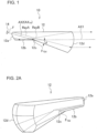
- FIG. 1 is a longitudinal cross-sectional view of the vehicular lamp fitting 10 according to Reference Example 1.
- a dotted line with an arrow at the end indicates an optical path of light from the light source 14 (to be more precise, the reference point F) which entered the lens body 12.
- the entry surface 12a is formed in the rear end of the lens body 12, and is a surface through which the light from the light source 14 (to be more precise, the reference point F in the optical design), which is disposed in the vicinity of the entry surface 12a (see FIG. 4A ), is refracted and enters the lens body 12 (e.g. free-form surface that is convex toward the light source 14), and the surface shape thereof is configured such that the light from the light source 14 (direct light RayA), which entered the lens body 12, is condensed toward the shade 12c in a direction closer to a second reference axis AX2 with respect to at least the vertical direction (see FIG. 4B ).
- the light source 14 includes, for example, a metal substrate (not illustrated), and a semiconductor light emitting element (not illustrated), such as a white LED (Light Emitting Diode) light source (or white LD (Laser Diode) light source) mounted on the surface of the substrate.
- a semiconductor light emitting element such as a white LED (Light Emitting Diode) light source (or white LD (Laser Diode) light source) mounted on the surface of the substrate.
- white LED Light Emitting Diode
- white LD Laser Diode
- the light source 14 may be a light source other than the semiconductor light emitting element, such as a white LED light source (or white LD light source).
- the light source 14 is disposed in the vicinity of the entry surface 12a of the lens body 12 (in the vicinity of the reference point F) in an attitude such that the light emitting surface (not illustrated) thereof faces forward and diagonally downward, in other words, in an attitude such that the optical axis AX 14 of the light source 14 matches the second reference axis AX2.
- the light source 14 may be disposed in the vicinity of the entry surface 12a of the lens body 12 (in the vicinity of the reference point F) in an attitude such that the optical axis AX 14 of the light source 14 does not match the second reference axis AX2 (e.g. in the attitude such that the optical axis AX 14 of the light source 14 is disposed in the horizontal direction).
- I( ⁇ ) denotes the luminous intensity of the light in the direction that is inclined from the optical axis AX 14 of the light source 14 by angle ⁇
- I0 denotes the luminous intensity on the optical axis AX 14 .
- FIG. 5 is an example of the entry surface 12a (cross-sectional view)
- FIG. 6 is another example of the entry surface 12a (cross-sectional view).
- the surface shape of the entry surface 12a is configured such that the light from the light source 14 which entered the lens body 12 (direct light RayA), is condensed toward the shade 12c in a direction closer to the first reference axis AX1 with respect to the horizontal direction.
- the surface shape of the entry surface 12a may be configured such that the light from the light source 14 which entered the lens body 12 (direct light RayA), becomes parallel with the reference axis AX1 with respect to the horizontal direction.
- the degree of diffusion of the low beam light distribution pattern in the horizontal direction can be freely adjusted by adjusting the surface shape of the entry surface 12a (e.g. curvature of the entry surface 12a in the horizontal direction).
- FIG. 7A and FIG. 7B are diagrams depicting the distance between the entry surface 12a and the light source 14.
- the light source image becomes smaller compared with the case of increasing the distance between the entry surface 12a and the light source 14 (see FIG. 7A ).
- the maximum luminous intensity of the luminous intensity distribution (and the low beam light distribution pattern) that is formed in the vicinity of the focal point F 12d of the exit surface 12d (lens unit) can be increased even more.
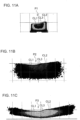
- the low beam light distribution patterns P1 to P3, illustrated in FIG. 11A to FIG. 11C are formed based on this light source image which includes the edges e1, e2 and e3 corresponding to the cut-off lines CL1 to CL3 defined on the upper edge by the shade 12c, hence the low beam light distribution patterns P1 to P3 include the clear cut-off lines CL1, CL2 and CL3 on the upper edges.
- the reflected light RayB' which was internally reflected by the reflection surface 12b, becomes a stray light RayB' which travels in a direction that does not enter the exit surface 12d. As a result, the efficiency drops.
- the second advantage is that the lens body 12 can be downsized compared with the case of disposing the reflection surface 12b in the horizontal direction.
- the height A (height in the vertical direction of the light which exits through the exit surface 12d) indicated in FIG. 14B , decreases 8% compared with the case illustrated in FIG. 14A
- the reflection surface 12b is disposed so as to be inclined with respect to the first reference axis AX1 by 10°
- the height A indicated in FIG. 14B decreases 18.1% compared with the case illustrated in FIG. 14A .
- the advantage is that stray light decreases and efficiency improves compared with the case of disposing the second reference axis AX2 in the horizontal direction and condensing the light from the light source 14 which entered the lens body 12 toward the shade 12c in a direction closer to the second reference axis AX2, at least with respect to the vertical direction.
- the stray light decreases and the efficiency improves compared with the case of disposing the second reference axis AX2 in the horizontal direction and condensing the light from the light source 14 which entered the lens body 12 toward the shade 12c in a direction closer to the second reference axis AX2, at least with respect to the vertical direction.
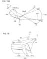
- FIG. 18 is a top view depicting a state where a plurality of vehicular lamp fittings 10 (plurality of lens bodies 12) of Reference Example 1 are disposed on a line.
- the first lens unit 12A1 includes the first entry surface 12a, the reflection surface 12b, the shade 12c, the first exit surface 12A1a and a reference point F that is disposed in the vicinity of the first entry surface 12a in the optical design.
- the second lens unit 12A2 includes the second entry surface 12A2a and the second exit surface 12A2b.
- the first entry surface 12a, the reflection surface 12b, the shade 12c, the first exit surface 12A1a, the second entry surface 12A2a, and the second exit surface 12A2b are disposed in this order along the first reference axis AX1.
- the first reference axis AX passes through a point (e.g. focal point F 12A4 ) in the vicinity of the shade 12c, and extends in the longitudinal direction of the vehicle.
- the second reference axis AX2 passes through the center (to be more precise, the reference point F) of the light source 14 and a point (e.g. focal point F 12A4 ) in the vicinity of the shade 12c, and is inclined forward and diagonally downward with respect to the first reference axis AX1.
- the surface shape of the first entry surface 12a may be configured such that the light from the light source 14, which entered the first lens unit 12A1, becomes parallel with the reference axis AX1 (see FIG. 6 ) with respect to the horizontal direction.
- this lens 12A4 is configured such that light reversely projects the luminous intensity distribution (light source image), which is formed in the vicinity of the focal point F 12A4 of the lens 12A4 by the light beams from the light source 14 which entered the first lens unit 12A1, (in other words, the direct light which travels toward the first exit surface 12A1a and the reflected light which was internally reflected by the reflection surface 12b and travels toward the first exit surface 12A1a, out of the light beams from the light source 14 which entered the first lens unit 12A1), and forms the low beam light distribution pattern P1a, including the cut-off lines CL1 to CL3 defined on an upper edge as illustrated in FIG. 20A on the virtual vertical screen.
- the luminous intensity distribution light source image
- the basic surface shape of the second exit surface 12A2b is as described above, but is actually adjusted as follows, since the extracting angles ⁇ and ⁇ are set for the first exit surface 12A1a and the second entry surface 12A2a.
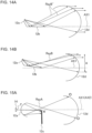
- FIG. 24 is a diagram depicting the normal lines of the first exit surface 12A1a, the second entry surface 12A2a, and the second exit surface 12A2b respectively.
- the normal lines N 12A1a and N 12A2a which pass through the centers of the first exit surface 12A1a and the second entry surface 12A2a, incline with respect to the horizontal line respectively, as illustrated in FIG. 24 .
- the normal line N 12A2b passing through the center of the second exit surface 12A2b, extends in the horizontal direction, the light from the light source 14, which exits through the second exit surface 12A2b, becomes light traveling diagonally upward with respect to the horizontal line, which may cause glare.
- the surface shape of the second exit surface 12A2b is adjusted so that the light from the light source 14, which exits through the second exit surface 12A2b, becomes parallel light with respect to the first reference axis AX1.
- the second exit surface 12A2b is adjusted to the surface shape of which the normal line N 12A2b thereof is inclined forward and diagonally upward, so that the light from the light source 14, which exits through the second exit surface 12A2b, becomes parallel light with respect to the first reference axis AX1.
- This adjustment is performed for matching the focal point F 12A4 of the lens 12A4 constituted by the first exit surface 12A1a and the second lens unit 12A2 (second entry surface 12A2a and second exit surface 12A2b) to a position in the vicinity of the shade 12c.
- the line with an arrow at the end in FIG. 24 indicates the optical path of the light from the light source 14 (to be more precise, the reference point F) which entered the lens body 12A.
- the light from the light source 14 enters the first lens unit 12A1 through the first entry surface 12a of the first lens unit 12A1, and exits through the first exit surface 12A1a of the first lens unit 12A1 after being partially shielded by the shade 12c of the first lens unit 12A1.
- the light from the light source 14, which exits through the first exit surface 12A1a is condensed in the horizontal direction by a function of the first exit surface 12A1a (see FIG. 22 .
- the light is not condensed or hardly condensed in the vertical direction).
- the light is not condensed, or hardly condensed in the horizontal direction).
- the combined lens body 16 includes a plurality of the lens bodies 12A.
- the combined lens body 16 (a plurality of the lens bodies 12A) is integrally molded by injecting such transparent resins as polycarbonate and acrylic into a die, and cooling and solidifying the resin (injection molding).
- the second exit surface 12A2b of each of the plurality of lens bodies 12A is disposed on a line in the horizontal direction so as to be adjacent to each other, and constitutes a semicircular cylindrical exit surface group having an integral appearance linearly extending in the horizontal direction.
- the combined lens body 16 may be configured by molding a plurality of lens bodies 12 in a physically separated state, and connecting (holding) the lens bodies 12 using a holding member (not illustrated), such as a lens holder.
- the integral appearance linearly extending in the horizontal direction can be implemented because the second exit surface 12A2b, which is the final exit surface, is configured as a semicircular cylindrical surface (semicircular cylindrical refractive surface extending in the horizontal direction).
- a lens body 12A (combined lens body 16) suitable for a vehicular lamp fitting, and a vehicular lamp fitting 10A equipped with the lens body 12A (combined lens body 16), are provided, whereby the light from the light source 14 exited from the second exit surface 12A2b, which is the final exit surface, becomes light parallel with the first reference axis AX1, even though the extracting angles ⁇ and ⁇ are set for the first exit surface 12A1a and the second entry surface 12A2a respectively.
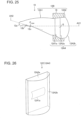
- FIG. 25 is a diagram depicting a lens body 12B, which is a first modification of the lens body 12A of Reference Example 2.
- the extracting angles ⁇ and ⁇ are unnecessary, therefore the adjustment of the second exit surface 12A2b can be omitted.
- the lens body 12C of this modification corresponds to Reference Example 2, where the first exit surface 12A1a and the second exit surface 12A2b are reversed.
- the second exit surface 12A2b of the lens body 12C of this modification is a surface configured to condense the light from the light source 14 which exits through the second exit surface 12A2b in the horizontal direction (corresponding to the second direction of the present invention).
- the second exit surface 12A2b is a semicircular cylindrical surface of which cylindrical axis extends in the vertical direction, which is not in accordance with the claimed present invention, but forms a reference example.
- the focal line of the second exit surface 12A2b extends in the vertical direction in the vicinity of the shade 12c.
- the combined lens body 16C includes a plurality of lens bodies 12C.
- the combined lens body 16C (plurality of lens bodies 12C) is integrally molded by injecting such transparent resins as polycarbonate and acrylic into a die, and cooling and solidifying the resin (injection molding).
- the second exit surface 12A2b of the plurality of lens bodies 12C is disposed on a line in the vertical direction so as to be adjacent to each other, and constitutes a semicircular cylindrical exit surface group having an integral appearance linearly extending in the vertical direction.
- a vehicular lamp fitting 10C having an integral appearance linearly extending in the virtual direction, can be configured.
- the combined lens body 16C may be configured by molding the plurality of lens bodies 12C in a physically separated state, and connecting (holding) the lens bodies 12C using a holding member (not illustrated), such as a lens holder.
- the integral appearance linearly extending in the vertical direction can be implemented because the second exit surface 12A2b, which is the final exit surface, is configured as a semicircular cylindrical surface (semicircular cylindrical refractive surface extending in the vertical direction).
- the low beam light distribution pattern P1a or the like, condensed in the horizontal direction and the vertical direction, can be formed even though the second exit surface 12A2b, which is the final exit surface, is a semicircular cylindrical surface (semicircular cylindrical refractive surface extending in the vertical direction), because condensing light in the vertical direction is mainly performed by the first exit surface 12A1a (semicircular cylindrical refractive surface extending in the horizontal direction) of the first lens unit 12A1, and condensing light in the horizontal direction is mainly performed by the second exit surface 12A2b (semicircular cylindrical refractive surface extending in the vertical direction) of the second lens unit 12A2, which is the final exit surface of the lens body 12A.
- the condensing functions are separated.
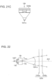
- FIG. 28 is a schematic diagram depicting the direct projection type vehicular lamp fitting 20 to which the concept "condensing functions are separated" is applied.
- the direct projection type vehicular lamp fitting 20 of Reference Example 3 corresponds to a standard direct projection type vehicular lamp fitting, in which a convex lens (convex lens of which final exit surface is a spherical surface) is replaced with the first lens unit 12A1 and the second lens unit 12A2.
- a focal point F 12A5 of a lens 12A5, constituted by the first lens unit 12A1 and the second lens unit 12A2, is set in the vicinity of the upper edge of the shade 22, which is disposed in front of the light source 14 in a state of covering a part of the light source 14 (light emitting surface).
- the first entry surface 12A1b is a plane-shaped (or curved plane-shaped) surface orthogonal to the reference axis AX1.
- the low beam light distribution pattern P1a or the like (corresponding to the predetermined light distribution pattern of the present invention), which includes the cut-off lines CL1 to CL3 defined on the upper edge by the shade 22, as illustrated in FIG. 20A , is formed on a virtual vertical screen.
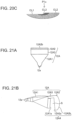
- a vehicular lamp fitting which forms a high beam light distribution pattern P Hi illustrated in FIG. 29 on a virtual vertical screen, can be configured by omitting the shade 22 in the configuration illustrated in FIG. 28 , and adjusting each surface 12A1a, 12A1b, 12A2a and 12A2b.
- the light from the light source 14 enters the first lens unit 12A1 through the first entry surface 12A1b of the first lens unit 12A1, and exits through the first exit surface 12A1a of the first lens unit 12A1.
- the light from the light source 14 is reflected by the reflector 32, enters the first lens unit 12A1 through the first entry surface 12A1b of the first lens unit 12A1 after being partially shielded by the shade 34, and exits through the first exit surface 12A1a of the first lens unit 12A1.
- the light from the light source 14, which exits through the first exit surface 12A1a is condensed in the horizontal direction by the function of the first exit surface 12A1a (the light is not condensed or hardly condensed in the vertical direction).
- a vehicular head light which formed a high beam light distribution pattern P Hi illustrated in FIG. 29 on a virtual vertical screen, can be configured.
- the light from the light source 14 is reflected by the reflector 32, enters the first lens unit 12A1 through the first entry surface 12A1b of the first lens unit 12A1, and exits through the first exit surface 12A1a of the first lens unit 12A1.
- the light from the light source 14, which exits through the first exit surface 12A1a is condensed in the horizontal direction by the function of the first exit surface 12A1a (the light is not condensed or hardly condensed in the vertical direction).
- the light from the light source 14, which exited through the first exit surface 12A1a passes through the space S, further enters the second lens unit 12A2 through the second entry surface 12A2a of the second lens unit 12A2, then exits through the second exit surface 12A2b of the second lens unit 12A2, and is irradiated forward.
- Embodiment 1 a vehicular lamp fitting 10D, in which a camber angle is added, will be described as Embodiment 1 with reference to the drawings.
- FIG. 34A is a cross-sectional view (of major optical surfaces only) at the position B in FIG. 32 , and a line with an arrow at the end in FIG. 34A indicates an optical path of the light Ray1B, which enters the first exit surface 12A1a (position B) at a predetermined entry angle.
- FIG. 34B is a cross-sectional view (of major optical surfaces only) at the position C in FIG. 32 , and a line with an arrow at the end in FIG. 34B indicates an optical path of the light Ray1C, which enters the first exit surface 12A1a (position C) at a same entry angle as FIG. 34A .
- the present inventors discovered that this blur is suppressed and the low beam light distribution pattern is generally condensed by adjusting the surface shape of the first exit surface 12A1a (see FIG. 31C ).
- the first exit surface 12A1a of Embodiment 1 is a semicircular cylindrical surface extending in the vertical direction, and the surface shape thereof is adjusted such that the low beam light distribution pattern is generally condensed (see FIG. 31C ).
- This adjustment is for matching the shifted- focal position FB, FC and the like with a position in the vicinity of the shade 12c, and is performed using a predetermined simulation software.
- FIG. 35A is a perspective view (of major optical surfaces only) of the vehicular lamp fitting 10D of Embodiment 1
- FIG. 35B is a comparative example, that is, a perspective view (of major optical surfaces only) of the vehicular lamp fitting 10A of Reference Example 2.
- the first exit surface 12A1a of Embodiment 1 adjusted as mentioned above, becomes non-symmetric-shaped with respect to the reference axis AX1.
- the vehicular lamp fitting 10D of Embodiment 1 is the same as the vehicular lamp fitting 10A of Reference Example 2, except for the above mentioned aspects.
- the reflection surface 12b and the shade 12c of Reference Example 7 are disposed in an attitude inclined with respect to the horizontal direction by the predetermined angle ⁇ 2 in the opposite direction of the second exit surface 12A2b and the first exit surface 12A1a when viewed from the front, similarly to Reference Example 6.
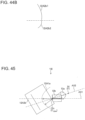
- second reference axis AX2 is inclined with respect to the first reference axis AX1 when viewed from the top
- Reference Example 9 is not limited to the vehicular lamp fitting 10A (lens body 12A) of Embodiment 1, but can be applied to each modification thereof, the vehicular lamp fittings (lens bodies) of Reference Examples 1 to 4, 6 to 8 and the like.
Landscapes
- Engineering & Computer Science (AREA)
- General Engineering & Computer Science (AREA)
- Microelectronics & Electronic Packaging (AREA)
- Physics & Mathematics (AREA)
- Optics & Photonics (AREA)
- Manufacturing & Machinery (AREA)
- Computer Hardware Design (AREA)
- Power Engineering (AREA)
- Mechanical Engineering (AREA)
- Non-Portable Lighting Devices Or Systems Thereof (AREA)
Description
- The present invention relates to a lens body and a vehicular lighting fixture.
- A vehicular lamp fitting having a structure of combining a light source and a lens body has been proposed (e.g.
JP 2005-228502 A - Another vehicular fitting having a structure of combining a light source and a lens body has been proposed (e.g.
JP 2012-094418 A - Another vehicular lamp fitting having a structure of combining a light source and a lens body has also been proposed (e.g.
JP 4037337 B -
DE 10 2013 006707 A1 discloses a motor vehicle headlight having at least one first light source and a headlight lens which comprises a blank-molded integrally formed body which is made from a transparent material, and which comprises at least one light tunnel and a light-conducting part having at least one optically effective light exit surface, wherein the light tunnel comprises, an optically effective, light entry surface and merges, while forming a kink, into the light-conducting part for imaging the kink as a light-dark boundary by means of light coupled in or radiated into the light entry surface from the first light source, wherein the light tunnel has a transition region in which the surface delimiting the light tunnel at the top rises in the direction of the light-conducting part. -
US 2008/151567 A1 discloses a motor vehicle headlight module giving a beam with cutoff, comprising a concave reflector, a light source disposed in the concavity of the reflector, and a lens situated in front of the reflector and light source. The source is formed by at least one light emitting diode for illuminating at least upwards. The reflector is associated with a bender the top face of which is reflective in order to bend the beam coming from the reflector, the bender comprising a front end edge able to form the cutoff in the lighting beam. The exit surface of the lenses chosen so as to be able to be connected on a continuous surface with the exit surfaces of the lenses of adjacent modules. In addition, the mid-line of the lens is formed by a skew curve arc, and a correcting optical system is provided between the reflector and the lens for obtaining a satisfactory cutoff line, according in particular to the geometry of the entry face and exit face of the lens. - In the vehicular lamp fitting according to
JP 2005-228502 A - With the foregoing in view, it is a first object of the present invention to provide a lens body (combined lens body) having an integral appearance linearly extending in a predetermined direction, and a vehicular lamp fitting equipped therewith.
- The present invention has been made in view of these circumstances, providing a lens body as set forth in
claim 1 and a vehicular lighting fixture as set forth in claim 7. Preferred embodiments of the present invention may be gathered from the dependent claims. -
-
FIG. 1 is a longitudinal cross-sectional view of the vehicular lamp fitting 10 according to Reference Example 1. -
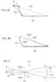
FIG. 2A is a perspective view of thelens body 12 when viewed from the front,FIG. 2B is a perspective view of thelens body 12 when viewed from the back. -
FIG. 3A is a top view,FIG. 3B is a bottom view, andFIG. 3C is a side view of thelens body 12. -
FIG. 4A is a diagram depicting a state when the light from the light source 14 (to be more precise, the reference point F) enters theentry surface 12a, andFIG. 4B is a diagram depicting a state when the light from thelight source 14, which entered the lens body 12 (direct light RayA), is condensed. -
FIG. 5 is an example of theentry surface 12a (cross-sectional view). -
FIG. 6 is another example of theentry surface 12a (cross-sectional view). -
FIG. 7A and FIG. 7B are diagrams depicting the distance between theentry surface 12a and thelight source 14. -
FIG. 8 is a diagram depicting functions of theshade 12c. -
FIG. 9A is a schematic diagram depicting theshade 12c when viewed from thelight source 14 position,FIG. 9B is an enlarged perspective view of thereflection surface 12b (including theshade 12c) illustrated inFIG. 2A , andFIG. 9C is a top view of thereflection surface 12b (including theshade 12c) illustrated inFIG. 2A . -
FIG. 10A to FIG. 10C illustrate modifications (side views) of theshade 12c. -
FIG. 11A illustrates the low beam light distribution pattern P1 on virtual vertical screen which faces the front face of the vehicle (disposed at about 25m in front of the front face of the vehicle),FIG. 11B illustrates a low beam light distribution pattern P2,FIG. 11C illustrates a low beam light distribution pattern P3. -
FIG. 12 is a diagram depicting the light source images formed by the light from thelight source 14 on each cross-section Cs1 to Cs4. -
FIG. 13A is a view illustrating how the reflected light Ray B 'reflected internally by the reflectingsurface 12 b advances in a direction in which the reflected light Ray B' does not enter theemitting surface 12 d when the reflectingsurface 12 b is arranged in the horizontal direction. -
FIG. 13B is a view depicting how the reflected light Ray B, which is internally reflected by thereflecting surface 12 b, travels in a direction in which it is incident on theexit surface 12 d when the reflectingsurface 12 b is disposed so as to be inclined with respect to the firstreference axis AX 1 is there. -
FIG. 14A is a view depicting how the reflected light RayB 'traveling in a direction that does not enter theoutgoing surface 12 d can be captured by extending the reflectingsurface 12 b upward when the reflectingsurface 12 b is arranged in the horizontal direction is there. -
FIG. 14B is a view illustrating a manner in which more light (reflected light RayB internally reflected by the reflectingsurface 12 b) can be captured without extending the reflectingsurface 12 b upward, in the case where the reflectingsurface 12 b is tilted with respect to the firstreference axis AX 1. -
FIG. 15A illustrates most of the light from thelight source 14 which entered thelens body 12 is shielded by theshade 12c, in the case of disposing the second reference axis AX2 in the horizontal direction and condensing the light from thelight source 14 which entered thelens body 12 toward theshade 12c in a direction closer to the second reference axis AX2 at least with respect to the vertical direction. -
FIG. 15B illustrates the light captured in theexit surface 12d (reflected light RayB internally reflected by thereflection surface 12b) increases, in the case of disposing the second reference axis AX2 so as to be inclined with respect to the first reference axis AX1 and condensing the light from thelight source 14 which entered thelens body 12 toward theshade 12c in a direction closer to the second reference axis AX2 at least with respect to the vertical direction. -
FIG. 16 is a perspective view of the vehicular lamp fitting 10A according to Reference Example 2. -
FIG. 17A is a longitudinal cross-sectional view thereof, andFIG. 17B is a diagram depicting the state of the light from thelight source 14 that travels inside alens body 12A. -
FIG. 18 is a top view depicting a state where a plurality of vehicular lamp fittings 10 (plurality of lens bodies 12) of Reference Example 1 are disposed on a line. -
FIG. 19A is a front view depicting the state where a plurality of thevehicular lamp fittings 10A (a plurality of thelens bodies 12A) according to Reference Example 2 are disposed on a line in the horizontal direction, andFIG. 19B is a top view thereof. -
FIG. 20A illustrates the low beam light distribution pattern P1a on virtual vertical screen which faces the front face of the vehicle (disposed at about 25m in front of the front face of the vehicle),FIG. 20B illustrates a low beam light distribution pattern P1b,FIG. 20C illustrates a low beam light distribution pattern P1c. -
FIG. 21A is a top view,FIG. 21B is a side view, andFIG. 21C is a bottom view of thelens body 12A of Reference Example 2. -
FIG. 22 illustrates an example of thefirst entry surface 12a (cross-sectional view). -
FIG. 23 is a perspective view depicting thelens body 12A (first exit surface 12A1a, second entry surface 12A2a and second exit surface 12A2b) of Reference Example 2. -
FIG. 24 is a diagram depicting the normal lines of the first exit surface 12A1a, the second entry surface 12A2a, and the second exit surface 12A2b respectively. -
FIG. 25 is a diagram depicting alens body 12B, which is a first modification of thelens body 12A of Reference Example 2. -
FIG. 26 is a perspective view depicting alens body 12C (first exit surface 12A1a, second entry surface 12A2a, second exit surface 12A2b), which is a second modification of thelens body 12A of Reference Example 2. -
FIG. 27 is a front view depicting a state where a plurality ofvehicular lamp fittings 10C (a plurality oflens bodies 12C) are disposed on a line in the vertical direction. -
FIG. 28 is a schematic diagram depicting the direct projection type vehicular lamp fitting 20 to which the concept "condensing functions are separated" is applied. -
FIG. 29 is an example of the high beam light distribution pattern PHi that is formed on a virtual vertical screen facing the front surface of the vehicle (disposed about 25 m in front of the front face of the vehicle). -
FIG. 30 is a schematic diagram depicting the projector type vehicular lamp fitting 30 to which the concept "condensing functions are separated" is applied. -
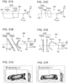
FIG. 31A is a side view (of major optical surfaces only) of the vehicular lamp fitting 10D in which a camber angle is added,FIG. 31B is a top view (of major optical surfaces only) thereof, andFIG. 31C is an example of a low beam light distribution pattern formed by the vehicular lamp fitting 10D. -
FIG. 31D to FIG. 31F depicting comparative examples, whereFIG. 31D is a side view (of major optical surfaces only) of the vehicular lamp fitting 10A of Reference Example 2 to which the camber angle is not added,FIG. 31E is a top view (of major optical surfaces only) thereof, andFIG. 31F is an example of a low beam light distribution pattern formed by the vehicular lamp fitting 10A of Reference Example 2. -
FIG. 32 is a top view (of major optical surfaces only) depicting a problem of the case of adding a comber angle. -
FIG. 33 is a drawing depicting a problem that appears in the low beam light distribution pattern when a comber angle is added. -
FIG. 34A is a cross-sectional view (of major optical surfaces only) at the position B inFIG. 32 ,FIG. 34B is a cross-sectional view (of major optical surfaces only) at the position C inFIG. 32 -
FIG. 35A is a perspective view (of major optical surfaces only) of the vehicular lamp fitting 10D ofEmbodiment 1,FIG. 35B is a comparative example, that is, a perspective view (of major optical surfaces only) of the vehicular lamp fitting 10A of Reference Example 2. -
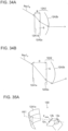
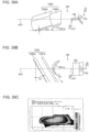
FIG. 36 is a front view of the vehicular lamp fitting 10E in which a slant angle is added. -
FIG. 37A is a drawing depicting a problem that appears in the low beam light distribution pattern when a slant angle is added, andFIG. 37B is a schematic diagram ofFIG. 37A . -
FIG. 38A is a drawing depicting a state when the problem (rotation) which appears in the low beam light distribution pattern was suppressed, andFIG. 38B is a schematic diagram ofFIG. 38A . -
FIG. 39A is a side view (of major optical surfaces only) of the vehicular lamp fitting 10F in which a camber angle and a slant angle are added,FIG. 39B is a top view (of major optical surfaces only) thereof, andFIG. 39C is an example of a low beam light distribution pattern formed by the vehicular lamp fitting 10F. -
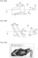
FIG. 40A is a side view (of major optical surfaces only) of the vehicular lamp fitting 10G according to the first comparative example,FIG. 40B is a top view (of major optical surfaces only) thereof, andFIG. 40C is an example of a light distribution pattern formed by the vehicular lamp fitting 10G. -
FIG. 41A is a side view (of major optical surfaces only) of the vehicular lamp fitting 10H of a second comparative example,FIG. 41B is a top view (of major optical surfaces only) thereof, andFIG. 41C is an example of a light distribution pattern formed by the vehicular lamp fitting 10H. -
FIG. 42A is an example of a low beam light distribution pattern formed by the vehicular lamp fitting 10D of Embodiment 1 (or the vehicular lamp fitting 10F of Reference Example 7), when the camber angle θ1 is 30°, andFIG. 42B is an example of a low beam light distribution pattern formed by the vehicular lamp fitting 10D of Embodiment 1 (or the vehicular lamp fitting 10F of Reference Example 7) when the camber angle θ1 is 45°. -
FIG. 43 is a cross-sectional view of the vehicular lamp fitting 10D (of major optical surfaces only) ofEmbodiment 1. -
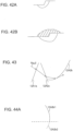
FIG. 44A is an example, where a partial region 12A2b2 of a lower part of the second exit surface 12A2b is physically cut-off and the upper region 12A2b1 remains. -
FIG. 44B is an example, where the surface shape (e.g. curvature) of the partial region 12A2b2 of a lower part of the second exit surface 12A2b is adjusted such that the light Ray2, which exits through the partial region 12A2b2, becomes light travelling in a parallel or downward direction with respect to the first reference axis AX, and the second exit surface 12A2b is separated into the upper region 12A2b1 and the lower region 12A2b2. -
FIG. 45 is a top view (of major optical surfaces only) of the vehicular lamp fitting 10I in which the second reference axis AX2 is inclined with respect to the first reference axis AX1 when viewed from the top. - A vehicular lamp fitting according to Reference Example 1 will be described with reference to the drawings.
-
FIG. 1 is a longitudinal cross-sectional view of the vehicular lamp fitting 10 according to Reference Example 1. - As illustrated in
FIG. 1 , the vehicular lamp fitting 10 according to Reference Example 1 includes alens body 12, and alight source 14 which is disposed in the vicinity of anentry surface 12a of thelens body 12, and is configured as a vehicular head light which forms a low beam light distribution pattern P1, which includes cut-off lines CL1 to CL3 on an upper edge illustrated inFIG. 11A on a virtual vertical screen which faces the front face of the vehicle (disposed at about 25m in front of the front face of the vehicle). -
FIG. 2A is a perspective view of thelens body 12 when viewed from the front,FIG. 2B is a perspective view of thelens body 12 when viewed from the back,FIG. 3A is a top view,FIG. 3B is a bottom view, andFIG. 3C is a side view of thelens body 12. - As illustrated in
FIG. 1 , thelens body 12 is a lens body having a shape along a first reference axis AX1 extending in the horizontal direction, and includes theentry surface 12a, areflection surface 12b, ashade 12c, anexit surface 12d, and a reference point F which is disposed in the vicinity of theentry surface 12a in the optical design. Theentry surface 12a, thereflection surface 12b, theshade 12c and theexit surface 12d are disposed in this order along the first reference axis AX1. The material of thelens body 12 may be polycarbonate, or other transparent resins, such as acrylic or glass. - In
FIG. 1 , a dotted line with an arrow at the end indicates an optical path of light from the light source 14 (to be more precise, the reference point F) which entered thelens body 12. - The major functions of the
lens body 12 are primarily capturing light from thelight source 14 in thelens body 12, and secondly forming a low beam light distribution pattern which includes a cut-off line on an upper edge, by inverting and projecting a luminous intensity distribution (light source image) which is formed in the vicinity of a focal point F12d of theexit surface 12d (lens unit) by direct light RayA, which travels toward theexit surface 12d and reflected light RayB, which is internally reflected on thereflection surface 12b, out of the light captured in thelens body 12. -
FIG. 4A is a diagram depicting a state when the light from the light source 14 (to be more precise, the reference point F) enters theentry surface 12a, andFIG. 4B is a diagram depicting a state when the light from thelight source 14, which entered the lens body 12 (direct light RayA), is condensed. - The
entry surface 12a is formed in the rear end of thelens body 12, and is a surface through which the light from the light source 14 (to be more precise, the reference point F in the optical design), which is disposed in the vicinity of theentry surface 12a (seeFIG. 4A ), is refracted and enters the lens body 12 (e.g. free-form surface that is convex toward the light source 14), and the surface shape thereof is configured such that the light from the light source 14 (direct light RayA), which entered thelens body 12, is condensed toward theshade 12c in a direction closer to a second reference axis AX2 with respect to at least the vertical direction (seeFIG. 4B ). The second reference axis AX2 passes through the center of the light source 14 (to be more precise, reference point F) and a point in the vicinity of theshade 12c, and is inclined forward and diagonally downward with respect to the first reference axis AX1 (seeFIG. 1 ). - The
light source 14 includes, for example, a metal substrate (not illustrated), and a semiconductor light emitting element (not illustrated), such as a white LED (Light Emitting Diode) light source (or white LD (Laser Diode) light source) mounted on the surface of the substrate. A number of the semiconductor light emitting elements is 1 or more. Thelight source 14 may be a light source other than the semiconductor light emitting element, such as a white LED light source (or white LD light source). Thelight source 14 is disposed in the vicinity of theentry surface 12a of the lens body 12 (in the vicinity of the reference point F) in an attitude such that the light emitting surface (not illustrated) thereof faces forward and diagonally downward, in other words, in an attitude such that the optical axis AX14 of thelight source 14 matches the second reference axis AX2. Thelight source 14 may be disposed in the vicinity of theentry surface 12a of the lens body 12 (in the vicinity of the reference point F) in an attitude such that the optical axis AX14 of thelight source 14 does not match the second reference axis AX2 (e.g. in the attitude such that the optical axis AX14 of thelight source 14 is disposed in the horizontal direction). - If the
light source 14 is a semiconductor light emitting element (e.g. white LED light source), the directional characteristic of the light emitted from the light source 14 (light emitting surface) has Lambertian light distribution, and can be expressed by I(θ) = I0 × cos θ. This expresses the diffusion of the light emitted from thelight source 14. Here I(θ) denotes the luminous intensity of the light in the direction that is inclined from the optical axis AX14 of thelight source 14 by angle θ, and I0 denotes the luminous intensity on the optical axis AX14. In thelight source 14, the luminous intensity is the maximum on the optical axis AX14 (θ = 0). -
FIG. 5 is an example of theentry surface 12a (cross-sectional view), andFIG. 6 is another example of theentry surface 12a (cross-sectional view). - As illustrated in
FIG. 5 , the surface shape of theentry surface 12a is configured such that the light from thelight source 14 which entered the lens body 12 (direct light RayA), is condensed toward theshade 12c in a direction closer to the first reference axis AX1 with respect to the horizontal direction. The surface shape of theentry surface 12a may be configured such that the light from thelight source 14 which entered the lens body 12 (direct light RayA), becomes parallel with the reference axis AX1 with respect to the horizontal direction. - The degree of diffusion of the low beam light distribution pattern in the horizontal direction can be freely adjusted by adjusting the surface shape of the
entry surface 12a (e.g. curvature of theentry surface 12a in the horizontal direction). -
FIG. 7A and FIG. 7B are diagrams depicting the distance between theentry surface 12a and thelight source 14. - By decreasing the distance between the
entry surface 12a and the light source 14 (seeFIG. 7B ), the light source image becomes smaller compared with the case of increasing the distance between theentry surface 12a and the light source 14 (seeFIG. 7A ). As a result, the maximum luminous intensity of the luminous intensity distribution (and the low beam light distribution pattern) that is formed in the vicinity of the focal point F12d of theexit surface 12d (lens unit) can be increased even more. - Further, by decreasing the distance between the
entry surface 12a and the light source 14 (seeFIG. 7B ), the light from thelight source 14 that is captured in thelens body 12 increases, compared with the case of increasing the distance between theentry surface 12a and the light source 14 (seeFIG. 7A ) (β > α). As a result, the efficiency of the lens body improves. - The
reflection surface 12b is a plane-shaped reflection surface extending forward in the horizontal direction from the lower edge of theentry surface 12a. Thereflection surface 12b is a reflection surface that totally reflects the light emitted onto thereflection surface 12b, out of the light from thelight source 14 which entered thelens body 12, and metal deposition is not performed on thereflection surface 12b. The light emitted onto thereflection surface 12b, out of the light from thelight source 14 which entered thelens body 12, is internally reflected by thereflection surface 12b and is directed to theexit surface 12d, is then refracted by theexit surface 12d, and finally directed to the road surface. In other words, the reflected light RayB, internally reflected by thereflection surface 12b, is returned at the cut-off line, and is superposed onto the light distribution pattern after the cut-off line. As a result, the cut-off line is formed on the upper edge of the low beam light distribution pattern. - The
reflection surface 12b may be a plane-shaped reflection surface inclined forward and diagonally downward from the lower edge of theentry surface 12a with respect to the first reference axis AX1 (seeFIG. 14B ). The advantage of disposing thereflection surface 12b to be inclined with respect to the first reference axis AX1 will be described later. - The
shade 12c extending in the crosswise direction is formed on the front end of thereflection surface 12b. -
FIG. 8 is a diagram depicting functions of theshade 12c. - As illustrated in
FIG. 8 , a main function of theshade 12c is to shield a part of the light from thelight source 14 which entered thelens body 12, and to form a luminous intensity distribution (light source image), that includes an edge corresponding to the cut-off line defined on the lower edge by theshade 12c, in the vicinity of the focal point F12d of theexit surface 12d (lens unit). -
FIG. 9A is a schematic diagram depicting theshade 12c when viewed from thelight source 14 position,FIG. 9B is an enlarged perspective view of thereflection surface 12b (including theshade 12c) illustrated inFIG. 2A , andFIG. 9C is a top view of thereflection surface 12b (including theshade 12c) illustrated inFIG. 2A . - As illustrated in
FIG. 2A andFIG. 9A toFIG. 9C , theshade 12c includes an edge e1 corresponding to a left horizontal cut-off line, an edge e2 corresponding to a right horizontal cut-off line, and an edge e3 corresponding to a diagonal cut-off line connecting the left horizontal cut-off line and the right horizontal cut-off line. - The
reflection surface 12b includes: a first reflection region 12b1 between the lower edge of theentry surface 12a and the edge e1 corresponding to the left horizontal cut-off line; a second reflection region 12b2 between the lower edge of theentry surface 12a and the edge e2 corresponding to the right horizontal cut-off line; and a third reflection region 12b3 between the first reflection region 12b1 and the second reflection region 12b2. - The first reflection region 12b1 gradually curves up from the lower edge of the
entry surface 12a approaching the edge e1 corresponding to the left horizontal cut-off line, and the second reflection region 12b2, on the other hand, extends forward from the lower edge of theentry surface 12a in the horizontal direction. - As a result, the edge e1 corresponding to the left horizontal cut-off line is disposed in a position that is one step higher in the vertical direction than the edge e2 corresponding to the right horizontal cut-off line (in the case of driving on the right-hand side). For certain, the edge e1 corresponding to the left horizontal cut-offline may be disposed in a position that is one step lower in the vertical direction than the edge e2 corresponding to the right horizontal cut-off line (in the case of driving on the left hand side).
- The
shade 12c may also be created by forming grooves on the front end of thereflection surface 12b, including: a groove corresponding to the left horizontal cut-off line, a groove corresponding to the right horizontal cut-off line, and a groove corresponding to the diagonal cut-off line connecting the left horizontal cut-off line and the right horizontal cut-off line. - In
FIG. 10A to FIG. 10C , modifications (side views) of theshade 12c are depicted. Theshade 12c may be extended upward from the front end of thereflection surface 12b (seeFIG. 10A ), may be extended forward and diagonally upward in a curved state (seeFIG. 10B ), or may be extended forward and diagonally upward (seeFIG. 10C ). Theshade 12c is not limited to these, but may have any shape as long as a part of the light from thelight source 14 that enters thelens body 12 is shielded so that this light does not travel toward theexit surface 12d. The shielded light may be used for other light distributions or optical guidings. - As illustrated in
FIG. 1 , theexit surface 12d is a surface (e.g. convex surface which protrudes forward) through which the direct light RayA, which is traveling toward theexit surface 12d, and the reflected light RayB, which is internally reflected by thereflection surface 12b and traveling toward theexit surface 12d, out of the light from thelight source 14 which entered thelens body 12, exit, and is configured as a lens unit of which focal point F12d is set in the vicinity of theshade 12c (e.g. in the vicinity of the center of theshade 12c in the crosswise direction). Theexit surface 12d reversely projects a luminous intensity distribution (light source image) formed in the vicinity of the focal point F12d of theexit surface 12d (lens unit) by the direct light RayA and the reflected light RayB traveling toward theexit surface 12d, and forms a low beam light distribution pattern which includes the cut-off line on the upper edge. - By increasing the distance between the
shade 12c and theexit surface 12d (focal length), the light source image becomes smaller compared with a case of decreasing the distance between theshade 12c and theexit surface 12d (focal length). As a result, the maximum luminous intensity of the luminous intensity distribution (and low beam light distribution pattern), which is formed in the vicinity of the focal point F12d of theexit surface 12d (lens unit), can be further increased. - Further, by decreasing the distance between the
exit surface 12d and the light source 14 (or theshade 12c), the direct light RayA and the reflected light RayB captured in the exit surface increases compared with a case of increasing the distance between theexit surface 12d and the light source 14 (or theshade 12c). As a result, efficiency improves. - The degree of diffusion of the low beam light distribution pattern in the horizontal direction and vertical direction can be freely adjusted by adjusting the surface shape of the
exit surface 12d. - The surface connecting the front edge of the
reflection surface 12b and the lower edge of theexit surface 12d is an inclined surface extending forward and diagonally downward from the front edge of thereflection surface 12b. The surface connecting the front edge of thereflection surface 12b and the lower edge of theexit surface 12d is not limited to this, but may be any surface as long as the surface does not shield the direct light RayA and the reflected light RayB travelling toward theexit surface 12d. In the same manner, the surface connecting the upper edge of theentry surface 12a and the upper edge of theexit surface 12d is a plane surface extending in the horizontal direction between the upper edge of theentry surface 12a and the upper edge of theexit surface 12d. However, the surface connecting the upper edge of theentry surface 12a and the upper edge of theexit surface 12d is not limited to this, but may be any surface as long as the surface does not shield the direct light RayA and the reflected light RayB travelling toward theexit surface 12d. - In the
lens body 12 having the above configuration, light which entered thelens body 12 through theentry surface 12a is condensed toward theshade 12c in a direction closer to the second reference axis AX2 with respect to the vertical direction (e.g. condensed to the center of theshade 12c). If the surface shape of theentry surface 12a is configured as illustrated inFIG. 5 , the light which entered the lens body through theentry surface 12a is condensed toward theshade 12c in a direction closer to the first reference axis AX1 with respect to the horizontal direction (e.g. condensed to the center of theshade 12c). - As described above, the direct light RayA condensed in the vertical direction and the horizontal direction and the reflected light RayB internally reflected by the
reflection surface 12b travel toward theexit surface 12d, and exit through theexit surface 12d. At this time, by the direct light RayA and the reflected light RayB travelling toward theexit surface 12d, the luminous intensity distribution (light source image), which includes the edge corresponding to the cut-off line defined on the lower edge by theshade 12c, is formed in the vicinity of the focal point F12d of theexit surface 12d (lens unit). Theexit surface 12d reversely projects this luminous intensity distribution and forms the low beam light distribution pattern P1, which includes the cut-off line on the upper edge, as illustrated inFIG. 11A on a virtual vertical screen. - This low beam light distribution pattern P1 has a central luminous intensity that is relatively high and excels in long range visibility. This is because the
light source 14 is disposed in the vicinity of theentry surface 12a (vicinity of the reference point F) of thelens body 12 in the attitude with which the optical axis AX14 of thelight source 14 matches with the second reference axis AX2, and because the light on the optical axis AX14 having relatively high intensity (luminous intensity) (direct light) is condensed toward theshade 12c in a direction closer to the second reference axis AX2 (e.g. condensed to the center of theshade 12c). - A low beam light distribution pattern P2, diffused in the horizontal direction, as illustrated in
FIG. 11B , can be formed by adjusting the surface shape (e.g. curvature) of theentry surface 12a and/or theexit surface 12d. - Further, the lower edge of the low beam light distribution pattern P1 or P2 can be extended downward by increasing the inclination of the second reference axis AX2 with respect to the first reference axis AX1 (see angle θ indicated in
FIG. 1 ). - If the surface shape of the
entry surface 12a is configured as illustrated inFIG. 6 , on the other hand, the light which entered thelens body 12 through theentry surface 12a becomes a light parallel with the first reference axis AX1 in the horizontal direction, as illustrated inFIG. 6 . - As described above, the direct light Ray A which condensed in the vertical direction and becomes parallel in the horizontal direction, and the reflected light RayB which is internally reflected by the
reflection surface 12b, travel toward theexit surface 12d and exit through theexit surface 12d. At this time, by the direct light RayA and the reflected light RayB, travelling toward theexit surface 12d, the luminous intensity distribution (light source image), which includes the edges corresponding to the cut-off lines CL1 to CL3, defined on the lower edge of theshade 12c, is formed in the vicinity of the focal point F12d of theexit surface 12d (lens unit). Theexit surface 12d reversely projects this luminous intensity distribution and forms a low beam light distribution pattern P3, which includes the cut-off lines CL1 to CL3 on the upper edge illustrated inFIG. 11C , on the virtual vertical screen. The low beam light distribution pattern P3 illustrated inFIG. 11C is not condensed in the horizontal direction, therefore the pattern is more diffused in the horizontal direction than the low beam light distribution pattern P1 illustrated inFIG. 11A . - Next, the relationship between the light source image formed by the light from the
light source 14, which entered thelens body 12, and the low beam distribution light distribution pattern, will be described. -
FIG. 12 is a diagram depicting the light source images formed by the light from thelight source 14 on each cross-section Cs1 to Cs3. - As illustrated in
FIG. 12 , the external shapes of the light source images ICs1 and ICs2 on the cross-sections Cs1 and Cs2 are the same as the external shape of the light source (the external shapes of the light source images are similar to and larger than the external shape of the light source 14). - The external shape of the light source image ICs3 on the cross-section CS3, after passing through the
reflection surface 12b and theshade 12c, includes the edges e1, e2 and e3 corresponding to the cut-off lines CL1 to CL3 defined on the lower edge by theshade 12c. This light source image ICs3 is inverted by the function of theexit surface 12d (lens unit), and includes the edges e1, e2 and e3 corresponding to the cut-off lines CL1 to CL3 defined by an upper edge by theshade 12c. - The low beam light distribution patterns P1 to P3, illustrated in
FIG. 11A to FIG. 11C , are formed based on this light source image which includes the edges e1, e2 and e3 corresponding to the cut-off lines CL1 to CL3 defined on the upper edge by theshade 12c, hence the low beam light distribution patterns P1 to P3 include the clear cut-off lines CL1, CL2 and CL3 on the upper edges. - Next, the advantages of disposing the
reflection surface 12b so as to be inclined with respect to the first reference axis AX1 will be described in comparison with the case of disposing thereflection surface 12b in the horizontal direction. - The first advantage is that stray light decreases and efficiency improves compared with the case of disposing the
reflection surface 12b in the horizontal direction. - In other words, in the case of disposing the
reflection surface 12b in the horizontal direction, as illustrated inFIG. 13A , the reflected light RayB', which was internally reflected by thereflection surface 12b, becomes a stray light RayB' which travels in a direction that does not enter theexit surface 12d. As a result, the efficiency drops. - On the other hand, in the case of disposing the
reflection surface 12b so as to be inclined with respect to the first reference axis AX1, as illustrated inFIG. 13B , the reflected light RayB, which was internally reflected by thereflection surface 12b and travels toward theexit surface 12d, increases, and light captured in theexit surface 12d (reflected light which was internally reflected by thereflection surface 12b) increases. As a result, the stray light decreases and the efficiency improves compared with the case of disposing thereflection surface 12b in the horizontal direction. - According to the simulation performed by the inventors of the present invention, in the case of disposing the
reflection surface 12b so as to be inclined with respect to the first reference axis AX1 by 5°, the efficiency increases 33.8%, and in the case of disposing thereflection surface 12b so as to be inclined with respect to the first reference axis AX1 by 10°, the efficiency increases 60%. - The second advantage is that the
lens body 12 can be downsized compared with the case of disposing thereflection surface 12b in the horizontal direction. - In other words, in the case of disposing the
reflection surface 12b in the horizontal direction, as illustrated inFIG. 13A , the reflected light RayB', which was internally reflected by thereflection surface 12b, becomes a stray light RayB' which travels in a direction that does not enter theexit surface 12d. By extending theexit surface 12d upward, as illustrated inFIG. 14A , the stray light RayB' can be captured, but the size of theexit surface 12d increases because of the upward extension. - On the other hand, in the case of disposing the
reflection surface 12b so as to be inclined with respect to the first reference axis AX1, as illustrated inFIG. 14B , theexit surface 12d can capture more light (reflected light RayB internally reflected by thereflection surface 12b) without extending theexit surface 12d upward. As a result, theexit surface 12d (and therefore the lens body 12) can be downsized compared with the case of disposing thereflection surface 12b in the horizontal direction. - According to the simulation performed by the inventors of the present invention, in the case of disposing the
reflection surface 12b so as to be inclined with respect to the first reference axis AX1 by 5°, the height A (height in the vertical direction of the light which exits through theexit surface 12d) indicated inFIG. 14B , decreases 8% compared with the case illustrated inFIG. 14A , and if thereflection surface 12b is disposed so as to be inclined with respect to the first reference axis AX1 by 10°, the height A indicated inFIG. 14B decreases 18.1% compared with the case illustrated inFIG. 14A . - Now an advantage of disposing the second reference axis AX2 so as to be inclined with respect to the first reference axis AX1, and condensing the light from the
light source 14 which entered thelens body 12 toward theshade 12c in a direction closer to the second reference axis AX2 at least with respect to the vertical direction, will be described in comparison with the case of disposing the second reference axis AX2 in the horizontal direction and condensing the light from thelight source 14 which entered thelens body 12 toward theshade 12c in a direction closer to the second reference axis AX2, at least with respect to the vertical direction. - The advantage is that stray light decreases and efficiency improves compared with the case of disposing the second reference axis AX2 in the horizontal direction and condensing the light from the
light source 14 which entered thelens body 12 toward theshade 12c in a direction closer to the second reference axis AX2, at least with respect to the vertical direction. - In other words, in the case of disposing the second reference axis AX2 in the horizontal direction and condensing the light from the
light source 14 which entered thelens body 12 toward theshade 12c in a direction closer to the second reference axis AX2 at least with respect to the vertical direction, as illustrated inFIG. 15A , most of the light from thelight source 14 which entered thelens body 12 is shielded by theshade 12c. As a result, the efficiency drops considerably. Even if a reflection surface corresponding to thereflection surface 12b is added inFIG. 15A , the reflected light internally reflected by this reflection surface becomes stray light which travels in a direction that does not enter theexit surface 12d. - On the other hand, in the case of disposing the second reference axis AX2 so as to be inclined with respect to the first reference axis AX1 and condensing the light from the
light source 14 which entered thelens body 12 toward theshade 12c in a direction closer to the second reference axis AX2 at least with respect to the vertical direction, as illustrated inFIG. 15B , the light captured in theexit surface 12d (reflected light RayB internally reflected by thereflection surface 12b) increases. As a result, the stray light decreases and the efficiency improves compared with the case of disposing the second reference axis AX2 in the horizontal direction and condensing the light from thelight source 14 which entered thelens body 12 toward theshade 12c in a direction closer to the second reference axis AX2, at least with respect to the vertical direction. - As described above, a
lens body 12, without including a reflection surface formed by metal deposition, which is a factor that increases cost, and a vehicular lamp fitting 10 equipped with thislens body 12, can be provided. Secondly, alens body 12 that can suppress melting of thelens body 12 and a drop in the output of thelight source 14, caused by the heat generated in thelight source 14, and a vehicular lamp fitting 10 equipped with thislens body 12, can be provided. - The reflection surface formed by metal deposition, which is a factor that increases cost, can be omitted, because the light from the
light source 14 is controlled not by the reflection surface formed by metal deposition, but by refraction on theentry surface 12a and internal reflection on thereflection surface 12b. - Melting of the
lens body 12 or a drop in the output of thelight source 14, caused by the heat generated in thelight source 14, can be suppressed, because theentry surface 12a is formed on the rear end of thelens body 12, and thelight source 14 is disposed outside the lens body 12 (that is, in a position distant from theentry surface 12a of the lens body 12). - Next, a vehicular lamp fitting according to Reference Example 2 will be described with reference to the drawings.
-
FIG. 16 is a perspective view of the vehicular lamp fitting 10A according to Reference Example 2,FIG. 17A is a longitudinal cross-sectional view thereof, andFIG. 17B is a diagram depicting the state of the light from thelight source 14 that travels inside alens body 12A. - The vehicular lamp fitting 10A of Reference Example 2 and the above mentioned vehicular lamp fitting 10 of Reference Example 1 are different mainly in the following aspects.
- Firstly, in the vehicular lamp fitting 10 of Reference Example 1, condensing in the horizontal direction and condensing in the vertical direction are mainly performed by the
exit surface 12d, which is the final exit surface, of thelens body 12, but in the vehicular lamp fitting 10A of Reference Example 2, condensing in the horizontal direction is mainly performed by a first exit surface 12A1a of a first lens unit 12A1, and condensing in the vertical direction is mainly performed by a second exit surface 12A2b of a second lens unit 12A2, which is the final exit surface of thelens body 12A. In other words, in the vehicular lamp fitting 10A of Reference Example 2, the concept "condensing functions are separated" is applied. - Secondly, in the vehicular lamp fitting 10 of Reference Example 1, the
exit surface 12d, which is the final exit surface of thelens body 12, is configured as a hemispherical surface (hemispherical refractive surface) in order to perform condensing in the horizontal direction and condensing in the vertical direction (seeFIG. 2A ), but in the vehicular lamp fitting 10A of Reference Example 2, the first exit surface 12A1a of the first lens unit 12A1 is configured as a semicircular cylindrical surface (semicircular cylindrical refractive surface) which extends in the vertical direction (seeFIG. 23 ) in order to perform condensing in the horizontal direction, and the second exit surface 12A2b of the second lens unit 12A2, which is the final exit surface of thelens body 12A, is configured as a semicircular cylindrical surface (semicircular cylindrical refractive surface) which extends in the horizontal direction (seeFIG. 23 ) in order to perform condensing in the vertical direction. - Thirdly, in the vehicular lamp fitting 10 of Reference Example 1, the
exit surface 12d, which is the final exit surface of thelens body 12, is configured as a hemispherical surface (hemispherical refractive surface), hence when a plurality of vehicular lamp fittings 10 (plurality of lens bodies 12) are disposed on a line (seeFIG. 18 ), dots appear as if lined up, and a vehicular lamp fitting (combined lens body) having an integral appearance linearly extending in a predetermined direction is not able to be implemented, while in the vehicular lamp fitting 10A of Reference Example 2, the second exit surface 12A2b, which is the final exit surface of thelens body 12A, is configured as a semicircular cylindrical surface (semicircular cylindrical refractive surface) extending in the horizontal direction, hence by disposing a plurality ofvehicular lamp fittings 10A (plurality oflens bodies 12A) on a line (seeFIG. 19A and FIG. 19B ), a vehicular lamp fitting (combined lens bodies 16), having an integral appearance linearly extending in the horizontal direction, can be configured.FIG. 18 is a top view depicting a state where a plurality of vehicular lamp fittings 10 (plurality of lens bodies 12) of Reference Example 1 are disposed on a line. - The other configuration is the same as the vehicular lamp fitting 10 of Reference Example 1. The vehicular lamp fitting 10A of Reference Example 2 will now be described focusing on the differences from the vehicular lamp fitting 10 of Reference Example 1, and a composing element the same as the vehicular lamp fitting 10 of Reference Example 1 will be denoted with a same reference symbol, and description thereof is omitted.
- As illustrated in
FIG. 16 andFIG. 17B , the vehicular lamp fitting 10A according to Reference Example 2 includes thelight source 14, the first lens unit 12A1, and the second lens unit 12A2, and is configured as a vehicular head light equipped with thelens body 12A, such that light from thelight source 14 enters the first lens unit 12A1 through afirst entry surface 12a of the first lens unit 12A1, exits through the first exit surface 12A1a of the first lens unit 12A1 after being partially shielded by theshade 12c of the first lens unit 12A1, further enters the second lens unit 12A2 through a second entry surface 12A2a of the second lens unit 12A2, then exits through a second exit surface 12A2b of the second lens unit 12A2, and is irradiated forward, so as to form a low beam light distribution pattern P1a or the like (corresponding to the predetermined light distribution pattern of the present invention), which includes cut-off lines CL1 to CL3 defined on an upper edge by theshade 12c illustrated inFIG. 20A . -
FIG. 21A is a top view,FIG. 21B is a side view, andFIG. 21C is a bottom view of thelens body 12A of Reference Example 2.FIG. 22 illustrates an example of thefirst entry surface 12a (cross-sectional view), andFIG. 23 is a perspective view depicting thelens body 12A (first exit surface 12A1a, second entry surface 12A2a and second exit surface 12A2b) of Reference Example 2. - As illustrated in
FIG. 17A andFIG. 21A toFIG. 21C , thelens body 12A is a lens body having a shape along the first reference axis AX extending in the horizontal direction, and includes the first lens unit 12A1, the second lens unit 12A2, and a connecting unit 12A3 which connects the first lens unit 12A1 and the second lens unit 12A2. - The first lens unit 12A1 includes the
first entry surface 12a, thereflection surface 12b, theshade 12c, the first exit surface 12A1a and a reference point F that is disposed in the vicinity of thefirst entry surface 12a in the optical design. The second lens unit 12A2 includes the second entry surface 12A2a and the second exit surface 12A2b. Thefirst entry surface 12a, thereflection surface 12b, theshade 12c, the first exit surface 12A1a, the second entry surface 12A2a, and the second exit surface 12A2b are disposed in this order along the first reference axis AX1. - The first lens unit 12A1 and the second lens unit 12A2 are connected by the connecting unit 12A3.
- The connecting unit 12A3 connects the first lens unit 12A1 and the second lens unit 12A2 at the upper portions thereof such that a space S (open area), surrounded by the first exit surface 12A1a, the second entry surface 12A2a and the connecting unit 12A3, is formed.
- The
lens body 12A is integrally molded by injecting such transparent resin as polycarbonate and acrylic into a die, and cooling and solidifying the resin (injection molding). - The space S is formed by a die of which the extracting direction is the opposite from the connecting unit 12A3 (see the arrow mark in
FIG. 17A ). To smoothly extracting the die, extracting angles α and β (also called "drafts", which are preferably 2° or more) are set for the first exit surface 12A1a and the second entry surface 12A2a respectively. Thereby the die can be vertically extracted during molding, and the lens body 12 (and the later mentioned combined lens body 16) can be manufactured by one extraction operation (without using a slide) at low cost. The material of thelens body 12A may be glass, other than such transparent resins as polycarbonate and acrylic. - The
first entry surface 12a is a surface which is formed in the rear end of the first lens unit 12A1 (e.g. free-form surface protruding toward the light source 14), and through which the light from the light source 14 (to be more precise, the reference point F in the optical design), disposed in the vicinity of thefirst entry surface 12a, is refracted and enters the first lens unit 12A1, and the surface shape of thefirst entry surface 12a is configured such that the light from thelight source 14, which entered the first lens unit 12A1, is condensed toward theshade 12c in a direction closer to the second reference axis AX2 with respect to the vertical direction (seeFIG. 17B ), and the light from thelight source 14 is condensed toward theshade 12c in a direction closer to the first reference axis AX1 with reference to the horizontal direction (seeFIG. 22 ). The first reference axis AX passes through a point (e.g. focal point F12A4) in the vicinity of theshade 12c, and extends in the longitudinal direction of the vehicle. The second reference axis AX2 passes through the center (to be more precise, the reference point F) of thelight source 14 and a point (e.g. focal point F12A4) in the vicinity of theshade 12c, and is inclined forward and diagonally downward with respect to the first reference axis AX1. The surface shape of thefirst entry surface 12a may be configured such that the light from thelight source 14, which entered the first lens unit 12A1, becomes parallel with the reference axis AX1 (seeFIG. 6 ) with respect to the horizontal direction. - The first exit surface 12A1a is a surface configured to condense the light beams from the
light source 14 which exited through the first exit surface 12A1a (in other words, the direct light which travels toward the first exit surface 12A1a and the reflected light which is internally reflected by thereflection surface 12b and travels toward the first exit surface 12A1a, out of the light beams from thelight source 14 which entered the first lens unit 12A1) in the horizontal direction (corresponding to the first direction of the present invention). In concrete terms, the first exit surface 12A1a is configured as a semicircular cylindrical surface of which cylindrical axis extends in the vertical direction, as illustrated inFIG. 23 . The focal line of the first exit surface 12A1a extends in the vicinity of theshade 12c in the vertical direction. - The second entry surface 12A2a is a surface which is formed on the rear end of the second lens unit 12A2, and through which the light from the
light source 14, which exited through the first exit surface 12A1a, enters the second lens unit 12A2, and is configured as a plane surface, for example. The surface shape of the second entry surface 12A2a is not limited to this, but may be configured as a curved surface. - The second exit surface 12A2b is a surface configured to condense the light from the
light source 14, which exited through the second exit surface 12A2b, in the vertical direction (corresponding to the second direction of the present invention). In concrete terms, the second exit surface 12A2b is configured as a semicircular cylindrical surface of which cylindrical axis extends in the horizontal direction, as illustrated inFIG. 23 . The focal line of the second exit surface 12A2b extends in the vicinity of theshade 12c in the horizontal direction. - Similarly to the focal point F12d of the
exit surface 12d of Reference Example 1, the focal point F12A4 of the lens 12A4, constituted by the first exit surface 12A1a and the second lens unit 12A2 (the second entry surface 12A2a and the second exit surface 12A2b) is set in the vicinity of theshade 12c (e.g. in the vicinity of the center of the crosswise direction of theshade 12c). Similarly to theexit surface 12d of Reference Example 1, this lens 12A4 is configured such that light reversely projects the luminous intensity distribution (light source image), which is formed in the vicinity of the focal point F12A4 of the lens 12A4 by the light beams from thelight source 14 which entered the first lens unit 12A1, (in other words, the direct light which travels toward the first exit surface 12A1a and the reflected light which was internally reflected by thereflection surface 12b and travels toward the first exit surface 12A1a, out of the light beams from thelight source 14 which entered the first lens unit 12A1), and forms the low beam light distribution pattern P1a, including the cut-off lines CL1 to CL3 defined on an upper edge as illustrated inFIG. 20A on the virtual vertical screen. - The basic surface shape of the second exit surface 12A2b is as described above, but is actually adjusted as follows, since the extracting angles α and β are set for the first exit surface 12A1a and the second entry surface 12A2a.
-
FIG. 24 is a diagram depicting the normal lines of the first exit surface 12A1a, the second entry surface 12A2a, and the second exit surface 12A2b respectively. - In other words, in the case when the extracting angles α and β are set for the first exit surface 12A1a and the second entry surface 12A2a, the normal lines N12A1a and N12A2a, which pass through the centers of the first exit surface 12A1a and the second entry surface 12A2a, incline with respect to the horizontal line respectively, as illustrated in
FIG. 24 . In this case, if the normal line N12A2b, passing through the center of the second exit surface 12A2b, extends in the horizontal direction, the light from thelight source 14, which exits through the second exit surface 12A2b, becomes light traveling diagonally upward with respect to the horizontal line, which may cause glare. - To suppress this, the surface shape of the second exit surface 12A2b is adjusted so that the light from the
light source 14, which exits through the second exit surface 12A2b, becomes parallel light with respect to the first reference axis AX1. For example, the second exit surface 12A2b is adjusted to the surface shape of which the normal line N12A2b thereof is inclined forward and diagonally upward, so that the light from thelight source 14, which exits through the second exit surface 12A2b, becomes parallel light with respect to the first reference axis AX1. This adjustment is performed for matching the focal point F12A4 of the lens 12A4 constituted by the first exit surface 12A1a and the second lens unit 12A2 (second entry surface 12A2a and second exit surface 12A2b) to a position in the vicinity of theshade 12c. The line with an arrow at the end inFIG. 24 indicates the optical path of the light from the light source 14 (to be more precise, the reference point F) which entered thelens body 12A. - The surface connecting the front edge of the
reflection surface 12b and the bottom edge of the first exit surface 12A1a is an inclined surface extending forward and diagonally downward from the front edge of thereflection surface 12b, but the surface is not limited to this, and may be any surface as long as the light from thelight source 14 traveling toward the second exit surface 12A2b is not shielded. In the same manner, the top surface of thelens body 12A, that is the surface connecting the upper edge of thefirst entry surface 12a and the upper edge of the second exit surface 12A2b, is a surface extending approximately in the horizontal direction, but the surface is not limited to this, and may be any surface as long as the light from thelight source 14 traveling toward the second exit surface 12A2b is not shielded. In the same manner, both side surfaces of thelens body 12A, which are surfaces connecting the left and right edges of thefirst entry surface 12a and the left and right edges of the second exit surface 12A2b, are inclined surfaces that are tapered toward thefirst entry surface 12a (seeFIG. 21A ), but the surfaces are not limited to this, and may be any surfaces as long as the light from thelight source 14 traveling toward the second exit surface 12A2b is not shielded. - In the vehicular lamp fitting 10A (
lens body 12A) having the above mentioned configuration, the light from thelight source 14 enters the first lens unit 12A1 through thefirst entry surface 12a of the first lens unit 12A1, and exits through the first exit surface 12A1a of the first lens unit 12A1 after being partially shielded by theshade 12c of the first lens unit 12A1. At this time, the light from thelight source 14, which exits through the first exit surface 12A1a, is condensed in the horizontal direction by a function of the first exit surface 12A1a (seeFIG. 22 . The light is not condensed or hardly condensed in the vertical direction). Then the light from thelight source 14, which exited through the first exit surface 12A1a, passes through the space S, further enters the second lens unit 12A2 through the second entry surface 12A2a of the second lens unit 12A2, exits through the second exit surface 12A2b of the second lens unit 12A2, and is irradiated forward. At this time, the light from thelight source 14, which exits through the second exit surface 12A2b, is condensed in the vertical direction by a function of the second exit surface 12A2b (seeFIG. 17B . The light is not condensed, or hardly condensed in the horizontal direction). Thereby the low beam light distribution pattern P1a or the like (corresponding to the predetermined light distribution pattern of the present invention) including the cut-off lines CL1 to CL3 defined on an upper edge by theshade 12c as illustrated inFIG. 20A , is formed on the virtual vertical screen. - This low beam light distribution pattern P1a or the like has a relatively high central luminous intensity and excellent long range visibility. This is because the
light source 14 is disposed in the vicinity of theentry surface 12a (in the vicinity of the reference point F) of thelens body 12A in an attitude such that the optical axis AX14 of thelight source 14 matches the second reference axis AX2, and that light on the optical axis AX14 (direct light) having a relatively high intensity (luminous intensity) is condensed toward theshade 12c in a direction closer to the second reference axis AX2 (e.g. condensed to the center of theshade 12c). - The degree of diffusion of the low beam light distribution pattern in the horizontal direction and/or the vertical direction can be freely adjusted as illustrated in
FIG. 20A to FIG. 20C by adjusting the surface shape (e.g. curvature) of the first exit surface 12A1a and/or the second exit surface 12A2b. For example, a degree of the diffusion of the low beam light distribution pattern in the horizontal direction can be freely adjusted by adjusting the surface shape (e.g. curvature) of the first exit surface 12A1a. In the same manner, a degree of diffusion of the low beam light distribution pattern in the vertical direction can be freely adjusted by adjusting the surface shape (e.g. curvature) of the second exit surface 12A2b. -
FIG. 19A is a front view depicting the state where a plurality of thevehicular lamp fittings 10A (a plurality of thelens bodies 12A) according to Reference Example 2 are disposed on a line in the horizontal direction, andFIG. 19B is a top view thereof. - As illustrated in
FIG. 19A and FIG. 19B , the combinedlens body 16 includes a plurality of thelens bodies 12A. The combined lens body 16 (a plurality of thelens bodies 12A) is integrally molded by injecting such transparent resins as polycarbonate and acrylic into a die, and cooling and solidifying the resin (injection molding). The second exit surface 12A2b of each of the plurality oflens bodies 12A is disposed on a line in the horizontal direction so as to be adjacent to each other, and constitutes a semicircular cylindrical exit surface group having an integral appearance linearly extending in the horizontal direction. - By using the combined
lens body 16 having the above mentioned configuration, a vehicular lamp fitting having an integral appearance, linearly extending in the horizontal direction, can be configured. The combinedlens body 16 may be configured by molding a plurality oflens bodies 12 in a physically separated state, and connecting (holding) thelens bodies 12 using a holding member (not illustrated), such as a lens holder. - As described above, according to Reference Example 2, the following effects can be implemented in addition to the above mentioned effects of Reference Example 1.
- Firstly, a
lens body 12A (combined lens body 16) having an integral appearance linearly extending in the horizontal direction, and a vehicular lamp fitting 10A equipped with thislens body 12A (combined lens body 16), can be provided. Secondly, alens body 12A (combined lens body 16) that can form a low beam light distribution pattern P1a or the like, condensed in the horizontal direction and the vertical direction, even though the second exit surface 12A2b, which is the final exit surface, is a semicircular cylindrical surface (semicircular cylindrical refractive surface extending in the horizontal direction), and a vehicular lamp fitting 10A equipped with thislens body 12A (combined lens body 16), can be provided. - The integral appearance linearly extending in the horizontal direction can be implemented because the second exit surface 12A2b, which is the final exit surface, is configured as a semicircular cylindrical surface (semicircular cylindrical refractive surface extending in the horizontal direction).
- The low beam light distribution pattern P1a or the like, condensed in the horizontal direction and the vertical direction, can be formed even though the second exit surface 12A2b, which is the final exit surface, is a semicircular cylindrical surface (semicircular cylindrical refractive surface extending in the horizontal direction), because condensing light in the horizontal direction is mainly performed by the first exit surface 12A1a (semicircular cylindrical refractive surface extending in the vertical direction) of the first lens unit 12A1, and condensing light in the vertical direction is mainly performed by the second exit surface 12A2b (semicircular cylindrical refractive surface extending in the horizontal direction ) of the second lens unit 12A2, which is the final exit surface of the
lens body 12A. In other words, the condensing functions are separated. - Further, according to Reference Example 2, a
lens body 12A (combined lens body 16) suitable for a vehicular lamp fitting, and a vehicular lamp fitting 10A equipped with thelens body 12A (combined lens body 16), are provided, whereby the light from thelight source 14 exited from the second exit surface 12A2b, which is the final exit surface, becomes light parallel with the first reference axis AX1, even though the extracting angles α and β are set for the first exit surface 12A1a and the second entry surface 12A2a respectively. - Next modifications will be described.
-
FIG. 25 is a diagram depicting alens body 12B, which is a first modification of thelens body 12A of Reference Example 2. - As illustrated in
FIG. 25 , thelens body 12B of this modification is configured by molding the first lens unit 12A1 and the second lens unit 12A2 in a physically separated state, and connecting (holding) these lens units by the holdingmember 18, such as a lens holder. The extracting angles α and β are not set for the first exit surface 12A1a and the second entry surface 12A2a, and are formed as a plane surface (or curved surface) orthogonal to the reference axis AX1. - According to this modification, the extracting angles α and β are unnecessary, therefore the adjustment of the second exit surface 12A2b can be omitted.
-
FIG. 26 is a perspective view depicting alens body 12C (first exit surface 12A1a, second entry surface 12A2a, second exit surface 12A2b), which is a second modification of thelens body 12A of Reference Example 2. - The
lens body 12C of this modification corresponds to Reference Example 2, where the first exit surface 12A1a and the second exit surface 12A2b are reversed. - In other words, the first exit surface 12A1a of the
lens body 12C of this modification is a surface configured to condense the light from thelight source 14 which exits through the first exit surface 12A1a in the vertical direction (corresponding to the first direction of the present invention). In concrete terms, as illustrated inFIG. 26 , the first exit surface 12A1a is a semicircular cylindrical surface of which cylindrical axis extends in the horizontal direction. In this case, the focal line of the first exit surface 12A1a extends in the horizontal direction in the vicinity of theshade 12c. The second exit surface 12A2b of thelens body 12C of this modification is a surface configured to condense the light from thelight source 14 which exits through the second exit surface 12A2b in the horizontal direction (corresponding to the second direction of the present invention). In concrete terms, as illustrated inFIG. 26 , the second exit surface 12A2b is a semicircular cylindrical surface of which cylindrical axis extends in the vertical direction, which is not in accordance with the claimed present invention, but forms a reference example. In this case, the focal line of the second exit surface 12A2b extends in the vertical direction in the vicinity of theshade 12c. - The focal point F12A4 of the lens 12A4, constituted by the first exit surface 12A1a and the second lens unit 12A2 (second entry surface 12A2a and second exit surface 12A2b) of the
lens body 12C of this modification, is set in the vicinity of theshade 12c (e.g. in the vicinity of the center of theshade 12c in the crosswise direction), similarly to Reference Example 2. -
FIG. 27 is a front view depicting a state where a plurality ofvehicular lamp fittings 10C (a plurality oflens bodies 12C) are disposed on a line in the vertical direction. - As illustrated in
FIG. 27 , the combinedlens body 16C includes a plurality oflens bodies 12C. The combinedlens body 16C (plurality oflens bodies 12C) is integrally molded by injecting such transparent resins as polycarbonate and acrylic into a die, and cooling and solidifying the resin (injection molding). The second exit surface 12A2b of the plurality oflens bodies 12C is disposed on a line in the vertical direction so as to be adjacent to each other, and constitutes a semicircular cylindrical exit surface group having an integral appearance linearly extending in the vertical direction. - By using the combined
lens body 16C having the above mentioned configuration, a vehicular lamp fitting 10C, having an integral appearance linearly extending in the virtual direction, can be configured. The combinedlens body 16C may be configured by molding the plurality oflens bodies 12C in a physically separated state, and connecting (holding) thelens bodies 12C using a holding member (not illustrated), such as a lens holder. - According to this modification, a
lens body 12C (combinedlens body 16C) having an integral appearance linearly extending in the vertical direction, and a vehicular lamp fitting 10C equipped with thislens body 12C (combinedlens body 16C), can be provided. Secondly, alens body 12C (combinedlens body 16C) that can form a low beam light distribution pattern P1a or the like condensed in the horizontal direction and the vertical direction, even though the second exit surface 12A2b, which is the final exit surface, is a semicircular cylindrical surface (semicircular cylindrical refractive surface extending in the vertical direction), and a vehicular lamp fitting 10C equipped with thislens body 12C (combinedlens body 16C), can be provided. - The integral appearance linearly extending in the vertical direction can be implemented because the second exit surface 12A2b, which is the final exit surface, is configured as a semicircular cylindrical surface (semicircular cylindrical refractive surface extending in the vertical direction).
- The low beam light distribution pattern P1a or the like, condensed in the horizontal direction and the vertical direction, can be formed even though the second exit surface 12A2b, which is the final exit surface, is a semicircular cylindrical surface (semicircular cylindrical refractive surface extending in the vertical direction), because condensing light in the vertical direction is mainly performed by the first exit surface 12A1a (semicircular cylindrical refractive surface extending in the horizontal direction) of the first lens unit 12A1, and condensing light in the horizontal direction is mainly performed by the second exit surface 12A2b (semicircular cylindrical refractive surface extending in the vertical direction) of the second lens unit 12A2, which is the final exit surface of the
lens body 12A. In other words, the condensing functions are separated. - The concept of "the condensing functions are separated" described in Reference Example 2 is not limited to the vehicular lamp fitting 10 of Reference Example 1, but can be applied to various vehicular lamp fittings (e.g. vehicular lamp fitting according to
Japanese Patent Application Laid-Open No. 2005-228502 - Next, a direct projection type vehicular lamp fitting 20, to which the concept "condensing functions are separated" described in Reference Example 2, is applied, will be described as Reference Example 3. A composing element the same as the vehicular lamp fitting 10A of Reference Example 2 will be denoted with a same reference symbol, and description thereof will be omitted.
-
FIG. 28 is a schematic diagram depicting the direct projection type vehicular lamp fitting 20 to which the concept "condensing functions are separated" is applied. - As illustrated in
FIG. 28 , the direct projection type vehicular lamp fitting 20, according to Reference Example 3, includes thelight source 14, the shade, 22, the first lens unit 12A1, and the second lens unit 12A2, and is configured as a vehicular head light equipped with a lens body, such that light from thelight source 14 enters the first lens unit 12A1 through a first entry surface 12A1b of the first lens unit 12A1 after being partially shielded by theshade 22, exits through a first exit surface 12A1a of the first lens unit 12A1, further enters the second lens unit 12A2 through the second entry surface 12A2a of the second lens unit 12A2, then exits through the second exit surface 12A2b of the second lens unit 12A2, and is irradiated forward, so as to form a low beam light distribution pattern P1a or the like (corresponding to the predetermined light distribution pattern of the present invention) which includes cut-off lines CL1 to CL3 defined on an upper edge by theshade 22 illustrated inFIG. 20A , on a virtual vertical screen. - In other words, the direct projection type vehicular lamp fitting 20 of Reference Example 3 corresponds to a standard direct projection type vehicular lamp fitting, in which a convex lens (convex lens of which final exit surface is a spherical surface) is replaced with the first lens unit 12A1 and the second lens unit 12A2. A focal point F12A5 of a lens 12A5, constituted by the first lens unit 12A1 and the second lens unit 12A2, is set in the vicinity of the upper edge of the
shade 22, which is disposed in front of thelight source 14 in a state of covering a part of the light source 14 (light emitting surface). Unlike Reference Example 2, the first entry surface 12A1b is a plane-shaped (or curved plane-shaped) surface orthogonal to the reference axis AX1. - In the vehicular lamp fitting 20 having the above mentioned configuration, the light from the
light source 14 enters the first lens unit 12A1 through the first entry surface 12A1b of the first lens unit 12A1 after being partially shielded by theshade 22, and exits through the first exit surface 12A1a of the first lens unit 12A1. At this time, the light from thelight source 14, which exits through the first exit surface 12A1a, is condensed in the horizontal direction by the function of the first exit surface 12A1a (the light is not condensed or hardly condensed in the vertical direction). Then the light from thelight source 14, which exited through the first exit surface 12A1a passes through the space S, further enters the second lens unit 12A2 through the second entry surface 12A2a of the second lens unit 12A2, exits through the second exit surface 12A2b of the second lens unit 12A2, and is irradiated forward. At this time, the light from thelight source 14, which exits through the second exit surface 12A2b, is condensed in the vertical direction by the function of the second exit surface 12A2b (the light is not condensed or hardly condensed in the horizontal direction). Thereby, the low beam light distribution pattern P1a or the like (corresponding to the predetermined light distribution pattern of the present invention), which includes the cut-off lines CL1 to CL3 defined on the upper edge by theshade 22, as illustrated inFIG. 20A , is formed on a virtual vertical screen. - A vehicular lamp fitting, which forms a high beam light distribution pattern PHi illustrated in
FIG. 29 on a virtual vertical screen, can be configured by omitting theshade 22 in the configuration illustrated inFIG. 28 , and adjusting each surface 12A1a, 12A1b, 12A2a and 12A2b. In this case, the light from thelight source 14 enters the first lens unit 12A1 through the first entry surface 12A1b of the first lens unit 12A1, and exits through the first exit surface 12A1a of the first lens unit 12A1. At this time, the light from thelight source 14, which exits through the first exit surface 12A1a, is condensed in the horizontal direction by the function of the first exit surface 12A1a (the light is not condensed or hardly condensed in the vertical direction). Then the light from thelight source 14, which exited through the first exit surface 12A1a, passes through the space S, further enters the second lens unit 12A2 through the second entry surface 12A2a of the second lens unit 12A2, exits through the second exit surface 12A2b of the second lens unit 12A2, and is irradiated forward. At this time, the light from thelight source 14, which exits through the second exit surface 12A2b, is condensed in the vertical direction by the function of the second exit surface 12A2b (the light is not condensed or hardly condensed in the horizontal direction). Thereby, the high beam light distribution pattern PHi, illustrated inFIG. 29 , is formed on a virtual vertical screen.FIG. 29 is an example of the high beam light distribution pattern PHi that is formed on a virtual vertical screen facing the front surface of the vehicle (disposed about 25 m in front of the front face of the vehicle). - Next, a projector type vehicular lamp fitting 30, to which the concept "condensing functions are separated", described in Reference Example 2, is applied, will be described as Reference Example 4. A composing element the same as the vehicular lamp fitting 10A of Reference Example 2 will be denoted with the same reference symbol, and description thereof will be omitted.
-
FIG. 30 is a schematic diagram depicting the projector type vehicular lamp fitting 30 to which the concept "condensing functions are separated" is applied. - As illustrated in
FIG. 30 , the projector type vehicular lamp fitting 30 according to Reference Example 4 includes thelight source 14, the reflector 32 (elliptical reflection surface), theshade 34, the first lens unit 12A1, and a second lens unit 12A2, and is configured as a vehicular head light equipped with a lens body, such that light from thelight source 14 is reflected by thereflector 32, enters the first lens unit 12A1 through a first entry surface 12A1b of the first lens unit 12A1 after being partially shaded by theshade 34, exits through the first exit surface 12A1a of the first lens unit 12A1, further enters the second lens unit 12A2 through the second entry surface 12A2a of the second lens unit 12A2, then exits through the second exit surface 12A2b of the second lens unit 12A2, and is irradiated forward, so as to form a low beam light distribution pattern P1a or the like (corresponding to the predetermined light distribution pattern of the present invention), which includes cut-off lines CL1 to CL3 defined on an upper edge by theshade 34, on a virtual vertical screen. - In other words, the projector type vehicular lamp fitting 30 of Reference Example 4 corresponds to a standard projector type vehicular lamp fitting, in which a convex lens (convex lens of which final exit surface is a spherical surface) is replaced with the first lens unit 12A1 and the second lens unit 12A2. The
shade 32 is configured as a mirror surface which extends backward in an approximately horizontal direction from the vicinity of a focal point F12A5 of the lens 12A5 constituted by the first lens unit 12A1 and the second lens unit 12A2. The focal point F12A5 of the lens 12A5 constituted by the first lens unit 12A1 and the second lens unit 12A2 is set in the vicinity of the front edge of theshade 34. A first focal point F1 of the reflector 32 (elliptical reflection surface) is set in the vicinity of thelight source 14, and a second focal point F2 approximately matches with the focal point F12A5 of the lens 12A5 constituted by the first lens unit 12A1 and the second lens unit 12A2. Unlike Reference Example 2, the first entry surface 12A1b is a plane surface (or curved plane surface) orthogonal to the reference axis AX1. - In the vehicular lamp fitting 30 having the above configuration, the light from the
light source 14 is reflected by thereflector 32, enters the first lens unit 12A1 through the first entry surface 12A1b of the first lens unit 12A1 after being partially shielded by theshade 34, and exits through the first exit surface 12A1a of the first lens unit 12A1. At this time, the light from thelight source 14, which exits through the first exit surface 12A1a, is condensed in the horizontal direction by the function of the first exit surface 12A1a (the light is not condensed or hardly condensed in the vertical direction). The light from thelight source 14, which exits through the first exit surface 12A1a, passes through the space S, further enters the second lens unit 12A2 through the second entry surface 12A2a of the second lens unit 12A2, then exits through the second exit surface 12A2b of the second lens unit 12A2, and is irradiated forward. At this time, the light from thelight source 14, which exits through the second exit surface 12A2b, is condensed in the vertical direction by the function of the second exit surface 12A2b (the light is not condensed or hardly condensed in the horizontal direction). Thereby, the low beam light distribution pattern P1a or the like (corresponding to the predetermined light distribution pattern of the present invention) illustrated inFIG. 20A , which includes cut-off lines CL1 to CL3 defined on an upper edge by theshade 34, is formed on a virtual vertical screen. - By omitting the
shade 34 from the configuration illustrated inFIG. 30 and adjusting the reflector 32 (elliptical reflection surface) and the like, a vehicular head light, which formed a high beam light distribution pattern PHi illustrated inFIG. 29 on a virtual vertical screen, can be configured. In this case, the light from thelight source 14 is reflected by thereflector 32, enters the first lens unit 12A1 through the first entry surface 12A1b of the first lens unit 12A1, and exits through the first exit surface 12A1a of the first lens unit 12A1. At this time, the light from thelight source 14, which exits through the first exit surface 12A1a, is condensed in the horizontal direction by the function of the first exit surface 12A1a (the light is not condensed or hardly condensed in the vertical direction). The light from thelight source 14, which exited through the first exit surface 12A1a, passes through the space S, further enters the second lens unit 12A2 through the second entry surface 12A2a of the second lens unit 12A2, then exits through the second exit surface 12A2b of the second lens unit 12A2, and is irradiated forward. At this time, the light from thelight source 14, which exited through the second exit surface 12A2b, is condensed in the vertical direction by the function of the second exit surface 12A2b (the light is not condensed or hardly condensed in the horizontal direction). Thereby, the high beam light distribution pattern PHi illustrated inFIG. 29 is formed on a virtual vertical screen. - Next a vehicular lamp fitting 10D, in which a camber angle is added, will be described as
Embodiment 1 with reference to the drawings. -
FIG. 31A is a side view (of major optical surfaces only) of the vehicular lamp fitting 10D in which a camber angle is added,FIG. 31B is a top view (of major optical surfaces only) thereof, andFIG. 31C is an example of a low beam light distribution pattern formed by the vehicular lamp fitting 10D.FIG. 31D to FIG. 31F depicting comparative examples, whereFIG. 31D is a side view (of major optical surfaces only) of the vehicular lamp fitting 10A of Reference Example 2 to which the camber angle is not added,FIG. 31E is a top view (of major optical surfaces only) thereof, andFIG. 31F is an example of a low beam light distribution pattern formed by the vehicular lamp fitting 10A of Reference Example 2.FIG. 32 is a top view (of major optical surfaces only) depicting a problem of the case of adding a comber angle. - As illustrated in
FIG. 31B , the vehicular lamp fitting 10D ofEmbodiment 1 corresponds to the vehicular lamp fitting 10A of Reference Example 2, in which the second lens unit 12A2 is inclined with respect to the first reference axis AX1 when viewed from the top, in other words, the vehicular lamp fitting 10D ofEmbodiment 1 corresponds to the vehicular lamp fitting 10A of Reference Example 2, in which the second exit surface 12A2b is configured as a semicircular cylindrical surface extending in a direction which is inclined with respect to the first reference axis AX1 by a predetermined angle (that is, a camber angle θ1 (e.g. θ1 = 30°) is added) when viewed from the top. - According to the simulation performed by the inventors of the present invention, if only the camber angle θ1 is added, the distance between the first exit surface 12A1a and the second entry surface 12A2a is different between each side of the first reference axis AX1 as illustrated in
FIG. 32 (see arrow B and arrow C inFIG. 32 ), and a focal position FB of the light which exits through a position B of the first exit surface 12A1a and a focal position Fc of the light which exits through a position C of the first exit surface 12A1a deviate considerably from each other, and as a result, as illustrated inFIG. 33 , the light is not condensed on the side where the distance between the first exit surface 12A1a and the second entry surface 12A2a is wider (right side inFIG. 33 ), in the low beam light distribution pattern formed on the virtual vertical screen, and the light distribution pattern blurs. - The cause of generating this blur will be described with reference to the drawings.
-
FIG. 34A is a cross-sectional view (of major optical surfaces only) at the position B inFIG. 32 , and a line with an arrow at the end inFIG. 34A indicates an optical path of the light Ray1B, which enters the first exit surface 12A1a (position B) at a predetermined entry angle.FIG. 34B is a cross-sectional view (of major optical surfaces only) at the position C inFIG. 32 , and a line with an arrow at the end inFIG. 34B indicates an optical path of the light Ray1C, which enters the first exit surface 12A1a (position C) at a same entry angle asFIG. 34A . To simplify description, the first exit surface 12A1a and the second entry surface 12A2a are illustrated without setting the extracting angles inFIG. 34A and FIG. 34B , butFIG. 34A and FIG. 34B are applicable to a case of setting the extracting angles. - As illustrated in
FIG. 34B , the distance between the first exit surface 12A1a and the second entry surface 12A2a is wider at the position C, compared with the position B (seeFIG. 34A ). Therefore the entry position of the light Ray1C to the second entry surface 12A2a becomes lower than the entry position of the light Ray1B to the second entry surface 12A2a illustrated inFIG. 34A , and the light RaylC that enters through this lower entry position travels upward, with respect to the horizontal direction, as illustrated inFIG. 34B . As a result, the above mentioned blur is generated. - As a result of keen examination to suppress this blur, the present inventors discovered that this blur is suppressed and the low beam light distribution pattern is generally condensed by adjusting the surface shape of the first exit surface 12A1a (see
FIG. 31C ). - Based on this knowledge, the first exit surface 12A1a of
Embodiment 1 is a semicircular cylindrical surface extending in the vertical direction, and the surface shape thereof is adjusted such that the low beam light distribution pattern is generally condensed (seeFIG. 31C ). This adjustment is for matching the shifted- focal position FB, FC and the like with a position in the vicinity of theshade 12c, and is performed using a predetermined simulation software.FIG. 35A is a perspective view (of major optical surfaces only) of the vehicular lamp fitting 10D ofEmbodiment 1,FIG. 35B is a comparative example, that is, a perspective view (of major optical surfaces only) of the vehicular lamp fitting 10A of Reference Example 2. As illustrated inFIG. 35A , the first exit surface 12A1a ofEmbodiment 1, adjusted as mentioned above, becomes non-symmetric-shaped with respect to the reference axis AX1. - The vehicular lamp fitting 10D of
Embodiment 1 is the same as the vehicular lamp fitting 10A of Reference Example 2, except for the above mentioned aspects. - According to
Embodiment 1, the following effects can be implemented in addition to the effects of Reference Example 2. - Firstly, a lens body (combined lens body) having a new appearance in which a camber angle is added, and a vehicular lamp fitting equipped with this lend body (combined lens body), can be provided. In other words, a lens body (combined lens body) having an integral appearance linearly extending in a direction inclined with respect to the first reference axis AX1 by a predetermined angle when viewed from the top, and a vehicular lamp fitting equipped with this lens body (combined lens body), can be provided. Secondly, a lens body (combined lens body), which can form a low beam light distribution pattern condensed in the horizontal direction and the vertical direction, even though the second exit surface 12A2b, which is the final exit surface, is a semicircular cylindrical surface (semicircular cylindrical refractive surface), and a vehicular lamp fitting equipped with this lens body (combined lens body), can be provided. Thirdly, a lens body (combined lens body) that can generally condense the low beam light distribution pattern, even though a camber angle is added, and a vehicular lamp fitting equipped with this lens body (combined lens body) can be provided.
- The integral appearance linearly extending in a direction inclined with respect to the first reference axis AX1 by a predetermined angle can be implemented, because the second exit surface 12A2b, which is the final exit surface, is configured as a semicircular cylindrical surface (semicircular cylindrical refractive surface), and this second exit surface 12A2b extends in a direction inclined with respect to the first reference axis AX1 when viewed from the top.
- The low beam light distribution pattern condensed in the horizontal direction and the vertical direction can be formed even though the second exit surface 12A2b, which is the final exit surface, is a semicircular cylindrical surface (semicircular cylindrical refractive surface), because condensing light in the horizontal direction is mainly performed by the first exit surface 12A1a (semicircular cylindrical refractive surface) of the first lens unit 12A1, and condensing light in the vertical direction is mainly performed by the second exit surface 12A2b (semicircular cylindrical refractive surface) of the second lens unit 12A2, which is the final exit surface of the
lens body 12A. In other words, the condensing functions are separated. - The low beam light distribution pattern is generally condensed even though the camber angle is added, because the first exit surface 12A1a is a semicircular cylindrical surface extending in the vertical direction, and the surface shape is adjusted such that the low beam light distribution pattern is generally condensed.
- The concept "the camber angle is added" described in
Embodiment 1 and the concept of suppressing the blur, which is generated by adding the camber angle, as described above, are not limited to the vehicular lamp fitting 10A (lens body 12A) of Reference Example 2, but can be applied to each modification thereof, the vehicular lamp fittings (lens bodies) of Reference Examples 3 and 4 and the like. These concepts can also be applied to the vehicular lamp fitting 10J (lens body 12J) of Reference Example 10, which will be described later. - Next, a vehicular lamp fitting 10E, in which a slant angle is added, will be described as Reference Example 6 with reference to the drawings.
-
FIG. 36 is a front view of the vehicular lamp fitting 10E in which a slant angle is added. - As illustrated in
FIG. 36 , the vehicular lamp fitting 10E of Reference Example 6 corresponds to the vehicular lamp fitting 10A of Reference Example 2, in which the second lens unit 12A2 is inclined with respect to the horizontal direction when viewed from the front, in other words, corresponds to the vehicular lamp fitting 10A of Reference Example 2, in which the second exit surface 12A2b is configured as a semicircular cylindrical surface extending in a direction which is inclined with respect to the horizontal direction by a predetermined angle Θ2 when viewed from the front (that is, a slant angle θ2 (e.g. Θ2 = 12°) is added). In concrete terms, the second lens unit 12A2 (second exit surface 12A2b) of Reference Example 6 corresponds to the second lens unit 12A2 (second exit surface 12A2b) of Reference Example 2, which is rotated around the first reference axis AX1 by a predetermined angle Θ2. - According to the simulation performed by the inventors of the present invention, if only the slant angle Θ2 is added, the focal line of the second lens unit 12A2 inclines with respect to the
shade 12c, and as a result, the low beam light distribution pattern formed on the virtual vertical screen is rotated (or blurred state), as illustrated inFIG. 37A and FIG. 37B. FIG. 37A is a drawing depicting a problem that appears in the low beam light distribution pattern when a slant angle is added, andFIG. 37B is a schematic diagram ofFIG. 37A . - As a result of keen examination to suppress this rotation (or blurred state), the present inventors discovered that the above mentioned rotation is suppressed (see
FIG. 38A and FIG. 38B ) by configuring the first exit surface 12A1a as a semicircular cylindrical surface extending in a direction which is inclined with respect to the vertical direction by a predetermined angle Θ2 when viewed from the front, and disposing thereflection surface 12b and theshade 12c in an attitude inclined with respect to the horizontal direction by the predetermined angle Θ2 in the opposite direction of the second exit surface 12A2b and the first exit surface 12A1a, as illustrated in IFG. 36.FIG. 38A is a drawing depicting a state when the problem (rotation) which appears in the low beam light distribution pattern was suppressed, andFIG. 38B is a schematic diagram ofFIG. 38A . - The reason why the rotation (or blurred state) is suppressed will be described with reference to the drawings.
- FIG. 52A is a side view of the vehicular lamp fitting 10E (
lens body 12A) of Reference Example 6 (of only major optical surfaces with omitting the first exit surface 12A1a) and FIG. 52B is a top view thereof (of only major optical surfaces with omitting the first exit surface 12A1a), and both indicate the optical path of parallel light RayAA, which entered thelens body 12A through the second exit surface 12A2b (that is, the result of reverse ray tracing). - FIG. 52C is a side view of the vehicular lamp fitting 10E (
lens body 12A) of Reference Example 6 (of only major optical surfaces with omitting the first exit surface 12A1a), and FIG. 52D is a top view thereof (of only major optical surfaces with omitting the first exit surface 12A1a), and both indicate the optical path of parallel light RayBB, which entered thelens body 12A through the second exit surface 12A2b (that is, the result of reverse ray tracing). - In FIG. 52A to FIG. 52D, the slant angle Θ2 (= 10°) is added to the second lens unit 12A2, and the focal line of the second lens unit 12A2 is inclined with respect to the horizontal line by the slant angle Θ2. As a result, the focal point FBB in FIG. 52C is positioned higher than the focal point FAA in FIG. 52A.
- The optical paths of the parallel light RayAA and RayBB in the case of disposing the first exit surface 12A1a, on the other hand, are illustrated in FIG. 53A and FIG. 53B.
- FIG. 53A is a top view when the first exit surface 12A1a is added to FIG. 52B, and indicates the optical path of the parallel light RayAA which entered the
lens body 12A through the second exit surface 12A2b (that is, the result of reverse ray tracing). FIG. 53B is a top view when the first exit surface 12A1a is added to FIG. 52D, and indicates the optical path of the parallel light RayBB which entered thelens body 12A through the second exit surface 12A2b (that is, the result of reverse ray tracing). - In the case of adding the slant angle Θ2 (= 10°) to the first exit surface 12A1a (that is, the case when the first exit surface 12A1a is configured as a semicircular cylindrical surface extending in a direction inclined with respect to the vertical direction by the predetermined angle θ2), the components having a low focal point FAA (that is, RayAA) are refracted because of the function of the first exit surface 12A1a, travel in the reverse direction, and are focused, as illustrated in FIG. 53A. The components having a high focal point FBB (that is, RayBB), on the other hand, are refracted because of the function of the first exit surface 12A1a, travel in the reverse direction, and are focused, as illustrated in FIG. 53B. As a result, the focal line is inclined in the opposite direction of the slant direction.
- In order to match (approximately match) the
shade 12c with the focal line inclined in the opposite direction of the slant direction, thereflection surface 12b and theshade 12c are disposed in an attitude inclined with respect to the horizontal line by the predetermined angle Θ2 in the opposite direction of the second exit surface 12A2b and the first exit surface 12A1a when viewed from the front. Thereby, theshade 12c matches (approximately matches) with the focal line, which is inclined in the opposite direction of the slant direction, and the above mentioned rotation (or blurred state) can be suppressed. - Based on this knowledge, the first exit surface 12A1a of Reference Example 6 is configured as a semicircular cylindrical surface extending in a direction inclined with respect to the vertical direction by the predetermined angle Θ2 when viewed from the front. In concrete terms, the first exit surface 12A1a of Reference Example 6 corresponds to the first exit surface 12A1a of Reference Example 2 that is rotated around the first reference axis AX1 by the predetermined angle Θ2 in the same direction as the second exit surface 12A2b.
- The
reflection surface 12b and theshade 12c are disposed in an attitude inclined with respect to the horizontal direction by the predetermined angle Θ2 in the opposite direction of the second exit surface 12A2b and the first exit surface 12A1a when viewed from the front. In concrete terms, thereflection surface 12b and theshade 12c of Reference Example 6 correspond to thereflection surface 12b and theshade 12c of Reference Example 2 that are rotated around the first reference axis AX1 by the predetermined angle Θ2 in the opposite direction of the second exit surface 12A2b and the first exit surface 12A1a. - The vehicular lamp fitting 10E of Reference Example 6 is the same as the vehicular lamp fitting 10A of Reference Example 2, except for the above mentioned aspects.
- According to Reference Example 6, the following effects can be implemented in addition to the effects of Reference Example 2.
- Firstly, a lens body (combined lens body) having a new appearance in which a slant angle is added, and a vehicular lamp fitting equipped with this lens body (combined lens body), can be provided. In other words, a lens body (combined lens body) having an integral appearance linearly extending in a direction inclined with respect to the horizontal direction by a predetermined angle when viewed from the front, and a vehicular lamp fitting equipped with this lens body (combined lens body), can be provided. Secondly, a lens body (combined lens body) which can form a low beam light distribution pattern condensed in the horizontal direction and the vertical direction, even though the second exit surface 12A2b, which is the final exit surface, is a semicircular cylindrical surface (semicircular cylindrical refractive surface), and a vehicular lamp fitting equipped with this lens body (combined lens body), can be provided. Thirdly, a lens body (combined body) that can suppress rotation of the low beam light distribution pattern, even though a slant angle is added, and a vehicular lamp fitting equipped with this lens body (combined lens body), can be provided.
- The integral appearance linearly extending in a direction inclined with respect to the horizontal direction by a predetermined angle can be implemented, because the second exit surface 12A2b, which is the final exit surface, is configured as a semicircular cylindrical surface (semicircular cylindrical refractive surface), and this second exit surface 12A2b extends in a direction inclined with respect to the horizontal direction when viewed from the front.
- The low beam light distribution pattern condensed in the horizontal direction and the vertical direction can be formed even though the second exit surface 12A2b, which is the final exit surface, is a semicircular cylindrical surface (semicircular cylindrical refractive surface), because condensing light in the horizontal direction is mainly performed by the first exit surface 12A1a (semicircular cylindrical refractive surface) of the first lens unit 12A1, and condensing light in the vertical direction is mainly performed by the second exit surface 12A2b (semicircular cylindrical refractive surface) of the second lens unit 12A2, which is the final exit surface of the
lens body 12A. In other words, the condensing functions are separated. - Rotation of the low beam light distribution pattern is suppressed even though the slant angle is added, because the first exit surface 12A1a is a semicircular cylindrical surface extending in a direction inclined with respect to the vertical direction by a predetermined angle, when viewed from the front, and the
shade 12c (and thereflection surface 12b) is disposed in an attitude inclined with respect to the horizontal direction by a predetermined angle in the opposite direction of the second exit surface 12A2b and the first exit surface 12A1a. - The concept of "the slant angle is added" described in Reference Example 6, and the concept of suppressing the rotation, which is generated by adding the slant angle, as described above, are not limited to the vehicular lamp fitting 10A (
lens body 12A) of Reference Example 2, but can be applied to each modification thereof, the vehicular lamp fittings (lens bodies) of Reference Examples 3 and 4 and the like. These concepts can also be applied to the vehicular lamp fitting 10J (lens body 12J) of Reference Example 10, which will be described later. - Next a vehicular lamp fitting 10F, in which a camber angle and a slant angle are added, will be described as Embodiment 2 with reference to the drawings.
-
FIG. 39A is a side view (of major optical surfaces only) of the vehicular lamp fitting 10F in which a camber angle and a slant angle are added,FIG. 39B is a top view (of major optical surfaces only) thereof, andFIG. 39C is an example of a low beam light distribution pattern formed by the vehicular lamp fitting 10F. - As illustrated in
FIG. 39A and FIG. 39B , the vehicular lamp fitting 10F of Reference Example 7 corresponds to the vehicular lamp fitting 10A of Reference Example 2, in which the second lens unit 12A2 is inclined with respect to the first reference axis AX1 (that is, the camber angle θ1 is added) when viewed from the top, and is inclined with respect to the horizontal direction (that is, a slant angle Θ2 is added) when viewed from the front, in other words, it corresponds to the combination ofEmbodiment 1 and Reference Example 6 described above. - In other words, the second exit surface 12A2b of Reference Example 7 extends in a direction inclined with respect to the first reference axis AX1 by a predetermined angle when viewed from the top, similarly to
Embodiment 1, and is configured as a semicircular cylindrical surface extending in a direction inclined with respect to the horizontal direction by the predetermined angle Θ2 when viewed from the front, similarly to Reference Example 6. - Further, the first exit surface 12A1a of Reference Example 7 is a semicircular cylindrical surface extending in a direction inclined with respect to the vertical direction by the predetermined angle Θ2 when viewed from the front (see
FIG. 36 ), and the surface shape thereof is adjusted so that the low beam light distribution pattern is generally condensed. - Furthermore, the
reflection surface 12b and theshade 12c of Reference Example 7 are disposed in an attitude inclined with respect to the horizontal direction by the predetermined angle Θ2 in the opposite direction of the second exit surface 12A2b and the first exit surface 12A1a when viewed from the front, similarly to Reference Example 6. - According to Reference Example 7, a lens body (combined lens body) having a new appearance in which a camber angle and a slant angle are added, and a vehicular lamp fitting equipped with the lens body (combined lens body), can be provided, and effects the same as
Embodiment 1 and Reference Example 6 can be implemented. - The concept "camber angle and the slant angle are added" described in Reference Example 7, and the concept of improving rotation and suppressing blur, which are generated by adding the camber angle and the slant angle, as described above, are not limited to the vehicular lamp fitting 10A (
lamp body 12A) of Reference Example 2, but can be applied to each modification thereof, the vehicular lamp fittings (lens bodies) of Reference Examples 3 and 4 and the like. These concepts can also be applied to the vehicular lamp fitting 10J (lens body 12J) of Reference Example 10, which will be described later. - Now a vehicular lamp fitting 10G, according to a first comparative example, will be described with reference to the drawings.
-
FIG. 40A is a side view (of major optical surfaces only) of the vehicular lamp fitting 10G according to the first comparative example,FIG. 40B is a top view (of major optical surfaces only) thereof, andFIG. 40C is an example of a light distribution pattern formed by the vehicular lamp fitting 10G. - As illustrated in
FIG. 40A and FIG. 40B , the vehicular lamp fitting 10G according to the first comparative example corresponds to the vehicular lamp fitting 10D ofEmbodiment 1, in which the second lens unit 12A2 is inclined with respect to the horizontal direction (that is, a slant angle Θ2 is added) when viewed from the front. - In other words, the first exit surface 12A1a of the first comparative example is configured as a semicircular cylindrical surface extending in the vertical direction when viewed from the front, similarly to
Embodiment 1. This means that, unlike Reference Example 6, the first exit surface 12A1a of the first comparative example is not configured as a semicircular cylindrical surface extending in a direction inclined with respect to the vertical direction by the predetermined angle Θ2 when viewed from the front. - Further, the
reflection surface 12b and theshade 12c of the first comparative example are disposed in a horizontal attitude when viewed from the front, similarly toEmbodiment 1. In other words, unlike Reference Example 6, the first exit surface 12A1a of the first comparative example is not disposed in an attitude inclined with respect to the horizontal direction by the predetermined angle Θ2 in the opposite direction of the second exit surface 12A2b and the first exit surface 12A1a. - As illustrated in
FIG. 40C , the light distribution pattern formed by the vehicular lamp fitting 10G of the first comparative example extends considerably above the horizontal line, which is not suitable for the low beam light distribution pattern, - Now a vehicular lamp fitting 10H according to a second comparative example will be described with reference to the drawings.
-
FIG. 41A is a side view (of major optical surfaces only) of the vehicular lamp fitting 10H of a second comparative example,FIG. 41B is a top view (of major optical surfaces only) thereof, andFIG. 41C is an example of a light distribution pattern formed by the vehicular lamp fitting 10H. - As illustrated in
FIG. 41A and FIG. 41B , the vehicular lamp fitting 10H of the second comparative example corresponds to the vehicular lamp fitting 10G of the first comparative example, in which the first exit surface 12A1a is configured as a semicircular cylindrical surface extending in a direction inclined with respect to the vertical direction by a predetermined angle θ2 when viewed from the front, similarly to Reference Example 6. - In other words, the first exit surface 12A1a of the second comparative example is configured as a semicircular cylindrical surface extending in a direction inclined with respect to the vertical direction by a predetermined angle θ2 when viewed from the front, similarly to Reference Example 6.
- Further, the
reflection surface 12b and theshade 12c of the second comparative example are disposed in a horizontal attitude when viewed from the front, similarly toEmbodiment 1. In other words, unlike Reference Example 6, the first exit surface 12A1a of the second comparative example is not disposed in an attitude inclined with respect to the horizontal direction by the predetermined angle θ2 in the opposite direction of the second exit surface 12A2b and the first exit surface 12A1a. - As illustrated in
FIG. 41C , the light distribution pattern formed by the vehicular lamp fitting 10H of second comparative example extends considerably above the horizontal line, which is not suitable for the low beam light distribution pattern. - Next a problem in the case of increasing the camber angle θ1 and a method for solving this problem will be described as Reference Example 8.
-
FIG. 42A is an example of a low beam light distribution pattern formed by the vehicular lamp fitting 10D of Embodiment 1 (or the vehicular lamp fitting 10F of Reference Example 7), when the camber angle θ1 is 30°, andFIG. 42B is an example of a low beam light distribution pattern formed by the vehicular lamp fitting 10D of Embodiment 1 (or the vehicular lamp fitting 10F of Reference Example 7) when the camber angle Θ1 is 45°. The hatched region inFIG. 42B indicates that this region is brighter compared with the corresponding region inFIG. 42A . - According to the simulation performed by the inventors of the present invention, if the camber angle θ1 is increased (e.g. Θ1 = 45°) in the vehicular lamp fitting 10D of Embodiment 1 (or the vehicular lamp fitting 10F of Reference Example 7), the area above the cut-off line becomes bright, as illustrated in
FIG. 42B . - The cause of this will be described with reference to the drawings.
-
FIG. 43 is a cross-sectional view of the vehicular lamp fitting 10D (of major optical surfaces only) ofEmbodiment 1. The line with an arrow at the end inFIG. 43 indicates an optical path of the light Ray2 from thelight source 14 which enters the first exit surface 12A1a at a certain entry angle. - If the camber angle θ1 is increased (e.g. Θ1 = 45°) in the vehicular lamp fitting 10D of Embodiment 1 (or the vehicular lamp fitting 10F of Reference Example 7), the distance between the first exit surface 12A1a and the second entry surface 12A2a increases, as illustrated in
FIG. 43 , compared with the case when the camber angle Θ1 is small (e.g. Θ1 = 30°). Therefore the entry position of the light Ray2 to the second entry surface 12A2a becomes lower compared with the case when the camber angle Θ1 is small (e.g. θ1 = 30°), and the light Ray2 that enters through the lower entry position becomes the light which travels diagonally upward with respect to the horizontal direction, as illustrated inFIG. 43 . As a result, glare is generated, and the cut-off line becomes unclear. - It is known that if the extracting angles α and β, which are set for the first exit surface 12A1a and the second entry surface 12A2a, are increased, the light Ray2 also becomes light which travels diagonally upward with respect to the horizontal direction, for the same reason as described above.
- A method for solving the problem will be described next.
- As a result of keen examination to suppress this problem, the present inventors discovered that the above mentioned light Ray2, which travels upward with respect to the horizontal direction, exits from a partial region of a lower part of the second exit surface 12A2b, and this problem can be suppressed by physically cutting off this partial region, or by adjusting the surface shape (e.g. curvature) of this partial region so that the light Ray2, which exits this partial region, becomes light traveling in parallel or downward with respect to the first reference axis AX.
-
FIG. 44A is an example based on this knowledge, where a partial region 12A2b2 of a lower part of the second exit surface 12A2b is physically cut-off and the upper region 12A2b1 remains. By cutting off a partial region through which the light, traveling diagonally upward with respect to the horizontal direction, exits like this, the light which travels diagonally upward can be suppressed. As a result, generation of glare is suppressed, and the cut-off line becomes clear. -
FIG. 44B is another example based on this knowledge, where the surface shape (e.g. curvature) of the partial region 12A2b2 of a lower part of the second exit surface 12A2b is adjusted such that the light Ray2, which exits through the partial region 12A2b2, becomes light travelling in a parallel or downward direction with respect to the first reference axis AX, and the second exit surface 12A2b is separated into the upper region 12A2b1 and the lower region 12A2b2. By adjusting the partial region through which the light, travelling diagonally upward with respect to the horizontal direction, exits like this, the light which travels diagonally upward can be suppressed. As a result, generation of glare is suppressed, and the cut-off line becomes clear. - The present inventors confirmed through simulation that the above mentioned problem, that is, the area above the cut-off line that becomes bright, can be suppressed by either one of these methods.
- Next, a vehicular lamp fitting 10I, in which the second reference axis AX1 is inclined with respect to the first reference axis AX1 when viewed from the top, will be described as Reference Example 9 with reference to the drawings.
-
FIG. 45 is a top view (of major optical surfaces only) of the vehicular lamp fitting 10I in which the second reference axis AX2 is inclined with respect to the first reference axis AX1 when viewed from the top. - As illustrated in
FIG. 45 , the vehicular lamp fitting 10I of Reference Example 9 corresponds to the vehicular lamp fitting 10D of Embodiment 1 (or the vehicular lamp fitting 10F of Reference Example 7), in which the second reference axis AX2 is rotated with the approximate center of theshade 12c in the crosswise direction as the rotation center by a predetermined angle, so as to be inclined with respect to the first reference axis AX1 when viewed from the top. - According to Reference Example 9, in addition to the above mentioned effects of
Embodiment 1, the Fresnel reflection loss (in particular, the Fresnel reflection loss in the second exit surface 12A2b, to which the camber angle is added, as illustrated inFIG. 45 ) is suppressed, and as a result, light utilization efficiency improves. - The concept "second reference axis AX2 is inclined with respect to the first reference axis AX1 when viewed from the top" described in Reference Example 9 is not limited to the vehicular lamp fitting 10A (
lens body 12A) ofEmbodiment 1, but can be applied to each modification thereof, the vehicular lamp fittings (lens bodies) of Reference Examples 1 to 4, 6 to 8 and the like.
Claims (9)
- A lens body (10) for a vehicle headlamp comprising a first lens unit (12A1) and a second lens unit (12A2) disposed along a first reference axis (AX1) which, in use, extends in the longitudinal direction of a vehicle, and configured such that light from a light source (14) entering the first lens unit through a first entry surface (12a, 12A1b) of the first lens unit (12A1), exits through a first exit surface (12A1a) of the first lens unit (12A1), further enters the second lens unit (12A2) through a second entry surface (12A2a) of the second lens unit (12A2), then exits through a second exit surface (12A2b) of the second lens unit (12A2), and is irradiated forward, so as to form a predetermined light distribution pattern (P1a, PHi),
characterized in thatthe second exit surface (12A2b) is a semicircular cylindrical surface, a cylindrical axis thereof extending in a direction inclined (θ1) with respect to the first reference axis (AX1) when viewed from the top, andwherein the first exit surface (12A1a) is a semicircular cylindrical surface, and the surface shapes of the first exit surface (12A1a) and of the second exit surface (12A2b) are adjusted such that the predetermined light distribution pattern (P1a, PHi) is generally condensed,wherein condensing light in the horizontal direction is mainly performed by the first exit surface and condensing light in the vertical direction is mainly performed by the second exit surface,
and/orwherein the first exit surface (12A1a) condenses light in a first direction and the second exit surface (12A2b) condenses light in a second direction, wherein the first and second directions are orthogonal. - The lens body according to claim 1, whereinthe first lens unit (12A1) includes a shade (12c),the light from the light source (14) enters the first lens unit (12A1) through the first entry surface (12a) of the first lens unit (12A1), exits through the first exit surface (12A1a) of the first lens unit (12A1) after being partially shielded by the shade (12c) of the first lens unit (12A1), so thatthe predetermined light distribution pattern (P1a, PHi) formed by the lens body includes a cut-off line defined on an upper edge by the shade (12c).
- The lens body according to claim 1 or 2, whereinthe first lens unit (12A1) includes a reflection surface (12b),the light from the light source (14) which exits through the first exit surface (12A1a) of the first lens unit (12A1) includes light reflected by the reflection surface (12b).
- The lens body according to any one of claim 1 to 3, wherein
the cylindrical axis of the first exit surface (12A1a) extends in the vertical direction. - The lens body according to claim 2, whereinthe cylindrical axis of the second exit surface (12A2b) extends in a direction inclined with respect to the horizontal direction by a predetermined angle (θ2) when viewed from the front,the cylindrical axis of the first exit surface (12A1a) extends in a direction inclined with respect to the vertical direction by the predetermined angle (θ2) when viewed from the front, andthe shade (12c) is disposed in an attitude inclined with respect to the horizontal direction by the predetermined angle (θ2) in the opposite direction of the second exit surface (12A2b) and the first exit surface (12A1a) when viewed from the front.
- The lens body according to claims 2 and 3, whereinthe first entry surface (12a), the reflection surface (12b), the shade (12c), the first exit surface (12A1a), the second entry surface (12A2a) and the second exit surface (12A2b) are disposed in this order along the first reference axis (AX1),the first entry surface (12a) is a surface through which the light from a light source (14), disposed in the vicinity of the first entry surface (12a), is refracted and enters the first lens unit (12A1), and which is configured such that the light from the light source (14), which entered the first lens unit (12A1), is condensed in a direction closer to a second reference axis (AX2) at least in the vertical direction, the second reference axis (AX2) passing through the center of the light source (14) and a point in the vicinity of the shade (12c) and inclined forward and diagonally downward with respect to the first reference axis (AX1),the reflection surface (12b) extends forward from the lower edge of the first entry surface (12A1b), andthe shade (12c) is formed in the front end of the reflection surface (12b).
- A vehicular lighting fixture, comprising:the lens body according to any one of claims 1 to 6,and a light source (14) disposed in the vicinity of the first entry surface (12a) of said lens body.
- The vehicular lighting fixture according to claim 7, wherein
the light source (14) is a LED light source. - A vehicular lighting fixture, comprising- the lens body according to claim 1 or to claim 4, and- a light source (14),- and elliptical reflection surface (32), wherein the light from the light source (14) reflected by the elliptical reflection surface (32) enters the first lens unit (12A1) through the first entry surface (12A1b) of the first lens unit (12A1), wherein a first focal point (F1) of the elliptical reflection surface (32) is set in the vicinity of the light source (14).
Applications Claiming Priority (7)
| Application Number | Priority Date | Filing Date | Title |
|---|---|---|---|
| JP2014107521A JP6256811B2 (en) | 2014-05-23 | 2014-05-23 | Lens body and vehicle lamp |
| JP2014107522A JP6260072B2 (en) | 2014-05-23 | 2014-05-23 | LENS BODY, LENS BODY AND VEHICLE LIGHT |
| JP2014107523A JP6260073B2 (en) | 2014-05-23 | 2014-05-23 | LENS BODY, LENS BODY AND VEHICLE LIGHT |
| JP2014122058A JP6288563B2 (en) | 2014-06-13 | 2014-06-13 | Lens body |
| JP2014195033A JP6361971B2 (en) | 2014-09-25 | 2014-09-25 | Lens body and vehicle lamp |
| PCT/JP2015/062374 WO2015178155A1 (en) | 2014-05-23 | 2015-04-23 | Lens body, combined lens body, and vehicular lamp fitting |
| EP15796951.0A EP3150905B1 (en) | 2014-05-23 | 2015-04-23 | Lens body, combined lens body, and vehicular lamp fitting |
Related Parent Applications (2)
| Application Number | Title | Priority Date | Filing Date |
|---|---|---|---|
| EP15796951.0A Division EP3150905B1 (en) | 2014-05-23 | 2015-04-23 | Lens body, combined lens body, and vehicular lamp fitting |
| EP15796951.0A Division-Into EP3150905B1 (en) | 2014-05-23 | 2015-04-23 | Lens body, combined lens body, and vehicular lamp fitting |
Publications (2)
| Publication Number | Publication Date |
|---|---|
| EP3333477A1 EP3333477A1 (en) | 2018-06-13 |
| EP3333477B1 true EP3333477B1 (en) | 2024-07-03 |
Family
ID=54553831
Family Applications (2)
| Application Number | Title | Priority Date | Filing Date |
|---|---|---|---|
| EP15796951.0A Active EP3150905B1 (en) | 2014-05-23 | 2015-04-23 | Lens body, combined lens body, and vehicular lamp fitting |
| EP18150378.0A Active EP3333477B1 (en) | 2014-05-23 | 2015-04-23 | Lens body, vehicle lighting feature |
Family Applications Before (1)
| Application Number | Title | Priority Date | Filing Date |
|---|---|---|---|
| EP15796951.0A Active EP3150905B1 (en) | 2014-05-23 | 2015-04-23 | Lens body, combined lens body, and vehicular lamp fitting |
Country Status (3)
| Country | Link |
|---|---|
| US (2) | US10352523B2 (en) |
| EP (2) | EP3150905B1 (en) |
| WO (1) | WO2015178155A1 (en) |
Families Citing this family (33)
| Publication number | Priority date | Publication date | Assignee | Title |
|---|---|---|---|---|
| DE112014006794B4 (en) | 2014-07-08 | 2022-03-10 | Mitsubishi Electric Corporation | Headlight module and headlight device |
| US9651212B1 (en) * | 2015-12-22 | 2017-05-16 | GM Global Technology Operations LLC | Light assembly |
| CN105546452B (en) * | 2016-02-01 | 2018-03-23 | 上海小糸车灯有限公司 | A kind of car light total reflection dipped beam combination module |
| KR20170129445A (en) * | 2016-05-17 | 2017-11-27 | 현대모비스 주식회사 | Lens assembly for implementing low-beam |
| ITUA20164809A1 (en) | 2016-06-30 | 2017-12-30 | Automotive Lighting Italia Spa | AUTOMOTIVE HEADLIGHT INCLUDING A PORTION OF LUMINOUS EMISSION WITH OPALESCENT EFFECT |
| TWI584633B (en) * | 2016-07-12 | 2017-05-21 | 台達電子工業股份有限公司 | Stereo Display Device |
| AT518552B1 (en) * | 2016-08-19 | 2017-11-15 | Zkw Group Gmbh | Lighting unit for a motor vehicle headlight for generating at least two light distributions |
| FR3055400B1 (en) * | 2016-09-01 | 2019-06-28 | Valeo Vision | OPTICAL MODULE FOR LIGHTING PORTIC POINTS |
| JP6720809B2 (en) | 2016-09-29 | 2020-07-08 | オムロン株式会社 | Light guide member, light guide member unit, and lighting device |
| KR102087412B1 (en) * | 2016-09-30 | 2020-03-12 | 에이취.에이.오토모티브 시스템스 인코퍼레이티드 | Condenser for short-range beam automotive lamp modules |
| WO2018133250A1 (en) * | 2017-01-19 | 2018-07-26 | 上海小糸车灯有限公司 | Led light source high-beam and low-beam integrated automobile lamp module with adb function |
| CN110462482B (en) * | 2017-03-17 | 2022-05-10 | 亮锐控股有限公司 | Multifocal collimating lens for automobile dipped beam and headlamp assembly |
| JP7042616B2 (en) | 2017-12-28 | 2022-03-28 | スタンレー電気株式会社 | Vehicle lighting |
| JP7016257B2 (en) | 2017-12-28 | 2022-02-21 | スタンレー電気株式会社 | Vehicle lighting |
| JP7042615B2 (en) * | 2017-12-28 | 2022-03-28 | スタンレー電気株式会社 | Vehicle headlights |
| JP7093641B2 (en) | 2018-02-08 | 2022-06-30 | スタンレー電気株式会社 | Vehicle lighting |
| WO2019154139A1 (en) | 2018-02-08 | 2019-08-15 | Jiaxing Super Lighting Electric Appliance Co., Ltd | Led lamp |
| US11143394B2 (en) | 2018-02-08 | 2021-10-12 | Jiaxing Super Lighting Electric Appliance Co., Ltd | LED lamp |
| US11226078B2 (en) * | 2018-04-23 | 2022-01-18 | Stanley Electric Co., Ltd. | Vehicular lamp fitting |
| JP7211655B2 (en) * | 2018-06-04 | 2023-01-24 | スタンレー電気株式会社 | vehicle lamp |
| FR3084755B1 (en) * | 2018-08-02 | 2020-12-18 | Valeo Vision | OPTICAL PART INCLUDING A BLOCK WITH A BENDING DIOPTER FOR TWO BEAMS |
| CN109140377B (en) * | 2018-08-03 | 2020-11-24 | 常熟理工学院 | Automobile headlamp unit |
| JP7218041B2 (en) * | 2019-05-21 | 2023-02-06 | 市光工業株式会社 | VEHICLE LIGHT GUIDE AND VEHICLE LAMP UNIT |
| CN111396824A (en) * | 2019-06-05 | 2020-07-10 | 华域视觉科技(上海)有限公司 | Car light optical element, car light module, vehicle headlamp and vehicle |
| US10753562B1 (en) * | 2019-06-09 | 2020-08-25 | Hossein ALISAFAEE | Lightguide headlamp |
| FR3097979B1 (en) * | 2019-06-28 | 2021-06-11 | Valeo Vision | Optical part intended to operate in total internal reflection |
| US10955681B2 (en) * | 2019-07-10 | 2021-03-23 | Abl Ip Holding Llc | Lighting device with miniature illumination light sources and optical lens sheet |
| DE112019007664T5 (en) * | 2019-08-30 | 2022-05-19 | Mitsubishi Electric Corporation | HEADLIGHT MODULE AND HEADLIGHT DEVICE |
| CN210601445U (en) * | 2019-10-25 | 2020-05-22 | 华域视觉科技(上海)有限公司 | Optical element of car lamp |
| CN211694701U (en) * | 2020-01-20 | 2020-10-16 | 华域视觉科技(上海)有限公司 | Headlamp optical element, headlamp module, lamp and vehicle |
| DE202020102825U1 (en) * | 2020-05-18 | 2020-06-19 | Nimbus Group Gmbh | Asymmetrical linear lens and associated linear lamp |
| US10865956B1 (en) * | 2020-05-28 | 2020-12-15 | T.Y.C. Brother Industrial Co., Ltd. | Vehicle light |
| US20230008568A1 (en) * | 2021-07-09 | 2023-01-12 | Varroc Lighting Systems, s.r.o. | Lighting and/or signaling device for a motor vehicle and a light guide therefor |
Family Cites Families (32)
| Publication number | Priority date | Publication date | Assignee | Title |
|---|---|---|---|---|
| JPH0738283B2 (en) * | 1988-07-12 | 1995-04-26 | 株式会社小糸製作所 | Automotive lighting |
| US5081564A (en) * | 1989-07-11 | 1992-01-14 | Koito Manufacturing Co., Ltd. | Vehicular lighting device |
| JPH0815412A (en) * | 1994-06-28 | 1996-01-19 | Nikon Corp | Light-beam projecting optical system |
| JPH09102203A (en) * | 1995-10-06 | 1997-04-15 | Denso Corp | Vehicular lamp device |
| JP4068387B2 (en) * | 2002-04-23 | 2008-03-26 | 株式会社小糸製作所 | Light source unit |
| JP4037337B2 (en) | 2003-07-24 | 2008-01-23 | 株式会社小糸製作所 | Lamp unit and vehicle headlamp |
| JP4339143B2 (en) | 2004-02-10 | 2009-10-07 | 株式会社小糸製作所 | Vehicle lamp unit |
| FR2872257B1 (en) | 2004-06-24 | 2006-08-18 | Valeo Vision Sa | LIGHTING MODULE FOR A MOTOR VEHICLE AND PROJECTOR COMPRISING SUCH A MODULE |
| FR2884899B1 (en) | 2005-04-21 | 2007-06-15 | Valeo Vision Sa | LIGHTING MODULE PROVIDING A LUMINOUS BEAM WITH CUT FOR A MOTOR VEHICLE PROJECTOR, AND PROJECTOR COMPRISING SUCH A MODULE |
| DE102006006635A1 (en) * | 2006-02-14 | 2007-08-16 | Schefenacker Vision Systems Germany Gmbh | Low beam headlamp, which produces a high-contrast cut-off |
| JP2007317596A (en) | 2006-05-29 | 2007-12-06 | Koito Mfg Co Ltd | Lamp unit for vehicle |
| FR2905448B1 (en) * | 2006-09-01 | 2015-05-01 | Valeo Vision | HIGH PERFORMANCE LIGHT GUIDE ASPECT LIGHTING OR SIGNALING DEVICE FOR VEHICLE. |
| FR2910592B1 (en) * | 2006-12-20 | 2012-07-20 | Valeo Vision | LUMINOUS PROJECTOR MODULE OF A MOTOR VEHICLE FOR A CUT-OFF BEAM |
| JP2009026462A (en) * | 2007-07-17 | 2009-02-05 | Toyoda Gosei Co Ltd | Lighting fixture for vehicle |
| JP2009266710A (en) * | 2008-04-28 | 2009-11-12 | Ichikoh Ind Ltd | Vehicular lighting fixture |
| JP5196314B2 (en) * | 2008-10-28 | 2013-05-15 | スタンレー電気株式会社 | Vehicle lamp and lens body |
| FR2948439B1 (en) | 2009-07-21 | 2011-08-05 | Valeo Vision | LIGHTING MODULE FOR A MOTOR VEHICLE PROJECTOR, AND PROJECTOR EQUIPPED WITH AT LEAST ONE SUCH MODULE. |
| JP5445923B2 (en) | 2009-09-04 | 2014-03-19 | スタンレー電気株式会社 | Vehicle lighting |
| JP5445049B2 (en) | 2009-11-13 | 2014-03-19 | スタンレー電気株式会社 | Vehicle lighting |
| EP2322848B1 (en) | 2009-11-12 | 2017-09-27 | Stanley Electric Co., Ltd. | Vehicle light |
| JP2011171083A (en) * | 2010-02-17 | 2011-09-01 | Stanley Electric Co Ltd | Light distribution pattern horizontal turnover device for low beam |
| JP5675272B2 (en) | 2010-10-28 | 2015-02-25 | 株式会社小糸製作所 | Vehicle lamp |
| CN103238025B (en) * | 2010-12-03 | 2016-02-03 | 博士光学欧洲股份公司 | For the optical module thrown light on |
| CN103890484B (en) * | 2011-11-11 | 2017-08-18 | 博士光学欧洲股份公司 | Headlamp lens and front lamp of vehicle for front lamp of vehicle |
| DE102013006707A1 (en) | 2012-05-26 | 2013-11-28 | Docter Optics Se | vehicle headlights |
| US8714793B2 (en) * | 2012-07-10 | 2014-05-06 | Osram Sylvania Inc. | LED headlight with one or more stepped upward-facing reflectors |
| US8733992B2 (en) * | 2012-10-01 | 2014-05-27 | Osram Sylvania, Inc. | LED low profile linear front fog module |
| JP2014075271A (en) * | 2012-10-04 | 2014-04-24 | Koito Mfg Co Ltd | Vehicular lighting fixture |
| US9939122B2 (en) * | 2013-05-17 | 2018-04-10 | Ichikoh Industries, Ltd. | Vehicle headlamp |
| JP6131724B2 (en) * | 2013-06-11 | 2017-05-24 | スタンレー電気株式会社 | Vehicle lighting |
| WO2015040671A1 (en) * | 2013-09-17 | 2015-03-26 | 三菱電機株式会社 | Vehicle-mounted headlight |
| DE102014205450A1 (en) * | 2014-03-24 | 2015-09-24 | Osram Gmbh | Light source arrangement |
-
2015
- 2015-04-23 EP EP15796951.0A patent/EP3150905B1/en active Active
- 2015-04-23 WO PCT/JP2015/062374 patent/WO2015178155A1/en active Application Filing
- 2015-04-23 EP EP18150378.0A patent/EP3333477B1/en active Active
-
2016
- 2016-11-21 US US15/357,643 patent/US10352523B2/en active Active
-
2019
- 2019-05-31 US US16/427,886 patent/US11009210B2/en active Active
Also Published As
| Publication number | Publication date |
|---|---|
| EP3150905A1 (en) | 2017-04-05 |
| EP3333477A1 (en) | 2018-06-13 |
| EP3150905B1 (en) | 2018-09-19 |
| US20170211771A1 (en) | 2017-07-27 |
| US20190301697A1 (en) | 2019-10-03 |
| EP3150905A4 (en) | 2017-06-21 |
| WO2015178155A1 (en) | 2015-11-26 |
| US10352523B2 (en) | 2019-07-16 |
| US11009210B2 (en) | 2021-05-18 |
Similar Documents
| Publication | Publication Date | Title |
|---|---|---|
| EP3333477B1 (en) | Lens body, vehicle lighting feature | |
| US11085603B2 (en) | Motor vehicle headlight module for emitting a light beam | |
| US9400089B2 (en) | Vehicle lighting unit | |
| CN101285561B (en) | Lamp unit for vehicle | |
| CN105066062B (en) | Light guide column and vehicle lamp using same | |
| JP6268476B2 (en) | Lens body and vehicle lamp | |
| EP3181992B1 (en) | Lighting device comprising a lens body and lighting tool. | |
| EP2767750A2 (en) | Vehicle headlight | |
| EP3163155A1 (en) | Diffusion light distribution optical system and vehicle lighting apparatus | |
| CN109073179B (en) | Vehicle lamp | |
| CN114270097A (en) | Headlamp module and headlamp device | |
| JP2014107049A (en) | Head light for vehicle | |
| EP3561373B1 (en) | Vehicular lamp fitting | |
| JP6256811B2 (en) | Lens body and vehicle lamp | |
| CN106764936B (en) | Lens body, lens combination body and vehicle lamp | |
| JP6659305B2 (en) | Lens body, lens assembly and vehicle lamp | |
| JP6260072B2 (en) | LENS BODY, LENS BODY AND VEHICLE LIGHT | |
| JP6288563B2 (en) | Lens body | |
| JP7028618B2 (en) | Vehicle lighting | |
| JP6376450B2 (en) | Lens body and vehicle lamp | |
| JP6523418B2 (en) | Vehicle headlights | |
| JP6523417B2 (en) | Vehicle headlights | |
| CN112555769B (en) | Lighting device | |
| JP6330246B2 (en) | Lens body and vehicle lamp | |
| JP2017103200A (en) | Lens body, lens combination and vehicular lighting fixture |
Legal Events
| Date | Code | Title | Description |
|---|---|---|---|
| PUAI | Public reference made under article 153(3) epc to a published international application that has entered the european phase |
Free format text: ORIGINAL CODE: 0009012 |
|
| STAA | Information on the status of an ep patent application or granted ep patent |
Free format text: STATUS: REQUEST FOR EXAMINATION WAS MADE |
|
| 17P | Request for examination filed |
Effective date: 20180104 |
|
| AC | Divisional application: reference to earlier application |
Ref document number: 3150905 Country of ref document: EP Kind code of ref document: P |
|
| AK | Designated contracting states |
Kind code of ref document: A1 Designated state(s): AL AT BE BG CH CY CZ DE DK EE ES FI FR GB GR HR HU IE IS IT LI LT LU LV MC MK MT NL NO PL PT RO RS SE SI SK SM TR |
|
| STAA | Information on the status of an ep patent application or granted ep patent |
Free format text: STATUS: EXAMINATION IS IN PROGRESS |
|
| STAA | Information on the status of an ep patent application or granted ep patent |
Free format text: STATUS: EXAMINATION IS IN PROGRESS |
|
| 17Q | First examination report despatched |
Effective date: 20211025 |
|
| GRAP | Despatch of communication of intention to grant a patent |
Free format text: ORIGINAL CODE: EPIDOSNIGR1 |
|
| STAA | Information on the status of an ep patent application or granted ep patent |
Free format text: STATUS: GRANT OF PATENT IS INTENDED |
|
| INTG | Intention to grant announced |
Effective date: 20240212 |
|
| GRAS | Grant fee paid |
Free format text: ORIGINAL CODE: EPIDOSNIGR3 |
|
| GRAA | (expected) grant |
Free format text: ORIGINAL CODE: 0009210 |
|
| STAA | Information on the status of an ep patent application or granted ep patent |
Free format text: STATUS: THE PATENT HAS BEEN GRANTED |
|
| AC | Divisional application: reference to earlier application |
Ref document number: 3150905 Country of ref document: EP Kind code of ref document: P |
|
| AK | Designated contracting states |
Kind code of ref document: B1 Designated state(s): AL AT BE BG CH CY CZ DE DK EE ES FI FR GB GR HR HU IE IS IT LI LT LU LV MC MK MT NL NO PL PT RO RS SE SI SK SM TR |
|
| REG | Reference to a national code |
Ref country code: CH Ref legal event code: EP |
|
| REG | Reference to a national code |
Ref country code: DE Ref legal event code: R096 Ref document number: 602015089137 Country of ref document: DE |