JP4068387B2 - Light source unit - Google Patents
Light source unit Download PDFInfo
- Publication number
- JP4068387B2 JP4068387B2 JP2002120346A JP2002120346A JP4068387B2 JP 4068387 B2 JP4068387 B2 JP 4068387B2 JP 2002120346 A JP2002120346 A JP 2002120346A JP 2002120346 A JP2002120346 A JP 2002120346A JP 4068387 B2 JP4068387 B2 JP 4068387B2
- Authority
- JP
- Japan
- Prior art keywords
- light
- light source
- source unit
- optical axis
- reflecting surface
- Prior art date
- Legal status (The legal status is an assumption and is not a legal conclusion. Google has not performed a legal analysis and makes no representation as to the accuracy of the status listed.)
- Expired - Fee Related
Links
Images


Classifications
-
- F—MECHANICAL ENGINEERING; LIGHTING; HEATING; WEAPONS; BLASTING
- F21—LIGHTING
- F21S—NON-PORTABLE LIGHTING DEVICES; SYSTEMS THEREOF; VEHICLE LIGHTING DEVICES SPECIALLY ADAPTED FOR VEHICLE EXTERIORS
- F21S41/00—Illuminating devices specially adapted for vehicle exteriors, e.g. headlamps
- F21S41/30—Illuminating devices specially adapted for vehicle exteriors, e.g. headlamps characterised by reflectors
- F21S41/32—Optical layout thereof
- F21S41/322—Optical layout thereof the reflector using total internal reflection
-
- F—MECHANICAL ENGINEERING; LIGHTING; HEATING; WEAPONS; BLASTING
- F21—LIGHTING
- F21S—NON-PORTABLE LIGHTING DEVICES; SYSTEMS THEREOF; VEHICLE LIGHTING DEVICES SPECIALLY ADAPTED FOR VEHICLE EXTERIORS
- F21S41/00—Illuminating devices specially adapted for vehicle exteriors, e.g. headlamps
- F21S41/30—Illuminating devices specially adapted for vehicle exteriors, e.g. headlamps characterised by reflectors
- F21S41/32—Optical layout thereof
- F21S41/33—Multi-surface reflectors, e.g. reflectors with facets or reflectors with portions of different curvature
-
- F—MECHANICAL ENGINEERING; LIGHTING; HEATING; WEAPONS; BLASTING
- F21—LIGHTING
- F21S—NON-PORTABLE LIGHTING DEVICES; SYSTEMS THEREOF; VEHICLE LIGHTING DEVICES SPECIALLY ADAPTED FOR VEHICLE EXTERIORS
- F21S41/00—Illuminating devices specially adapted for vehicle exteriors, e.g. headlamps
- F21S41/10—Illuminating devices specially adapted for vehicle exteriors, e.g. headlamps characterised by the light source
- F21S41/14—Illuminating devices specially adapted for vehicle exteriors, e.g. headlamps characterised by the light source characterised by the type of light source
- F21S41/141—Light emitting diodes [LED]
- F21S41/147—Light emitting diodes [LED] the main emission direction of the LED being angled to the optical axis of the illuminating device
- F21S41/148—Light emitting diodes [LED] the main emission direction of the LED being angled to the optical axis of the illuminating device the main emission direction of the LED being perpendicular to the optical axis
-
- F—MECHANICAL ENGINEERING; LIGHTING; HEATING; WEAPONS; BLASTING
- F21—LIGHTING
- F21S—NON-PORTABLE LIGHTING DEVICES; SYSTEMS THEREOF; VEHICLE LIGHTING DEVICES SPECIALLY ADAPTED FOR VEHICLE EXTERIORS
- F21S41/00—Illuminating devices specially adapted for vehicle exteriors, e.g. headlamps
- F21S41/10—Illuminating devices specially adapted for vehicle exteriors, e.g. headlamps characterised by the light source
- F21S41/14—Illuminating devices specially adapted for vehicle exteriors, e.g. headlamps characterised by the light source characterised by the type of light source
- F21S41/141—Light emitting diodes [LED]
- F21S41/151—Light emitting diodes [LED] arranged in one or more lines
-
- F—MECHANICAL ENGINEERING; LIGHTING; HEATING; WEAPONS; BLASTING
- F21—LIGHTING
- F21S—NON-PORTABLE LIGHTING DEVICES; SYSTEMS THEREOF; VEHICLE LIGHTING DEVICES SPECIALLY ADAPTED FOR VEHICLE EXTERIORS
- F21S41/00—Illuminating devices specially adapted for vehicle exteriors, e.g. headlamps
- F21S41/10—Illuminating devices specially adapted for vehicle exteriors, e.g. headlamps characterised by the light source
- F21S41/14—Illuminating devices specially adapted for vehicle exteriors, e.g. headlamps characterised by the light source characterised by the type of light source
- F21S41/141—Light emitting diodes [LED]
- F21S41/155—Surface emitters, e.g. organic light emitting diodes [OLED]
-
- F—MECHANICAL ENGINEERING; LIGHTING; HEATING; WEAPONS; BLASTING
- F21—LIGHTING
- F21S—NON-PORTABLE LIGHTING DEVICES; SYSTEMS THEREOF; VEHICLE LIGHTING DEVICES SPECIALLY ADAPTED FOR VEHICLE EXTERIORS
- F21S41/00—Illuminating devices specially adapted for vehicle exteriors, e.g. headlamps
- F21S41/10—Illuminating devices specially adapted for vehicle exteriors, e.g. headlamps characterised by the light source
- F21S41/14—Illuminating devices specially adapted for vehicle exteriors, e.g. headlamps characterised by the light source characterised by the type of light source
- F21S41/16—Laser light sources
-
- F—MECHANICAL ENGINEERING; LIGHTING; HEATING; WEAPONS; BLASTING
- F21—LIGHTING
- F21S—NON-PORTABLE LIGHTING DEVICES; SYSTEMS THEREOF; VEHICLE LIGHTING DEVICES SPECIALLY ADAPTED FOR VEHICLE EXTERIORS
- F21S41/00—Illuminating devices specially adapted for vehicle exteriors, e.g. headlamps
- F21S41/20—Illuminating devices specially adapted for vehicle exteriors, e.g. headlamps characterised by refractors, transparent cover plates, light guides or filters
- F21S41/24—Light guides
-
- F—MECHANICAL ENGINEERING; LIGHTING; HEATING; WEAPONS; BLASTING
- F21—LIGHTING
- F21S—NON-PORTABLE LIGHTING DEVICES; SYSTEMS THEREOF; VEHICLE LIGHTING DEVICES SPECIALLY ADAPTED FOR VEHICLE EXTERIORS
- F21S41/00—Illuminating devices specially adapted for vehicle exteriors, e.g. headlamps
- F21S41/20—Illuminating devices specially adapted for vehicle exteriors, e.g. headlamps characterised by refractors, transparent cover plates, light guides or filters
- F21S41/25—Projection lenses
-
- F—MECHANICAL ENGINEERING; LIGHTING; HEATING; WEAPONS; BLASTING
- F21—LIGHTING
- F21V—FUNCTIONAL FEATURES OR DETAILS OF LIGHTING DEVICES OR SYSTEMS THEREOF; STRUCTURAL COMBINATIONS OF LIGHTING DEVICES WITH OTHER ARTICLES, NOT OTHERWISE PROVIDED FOR
- F21V2200/00—Use of light guides, e.g. fibre optic devices, in lighting devices or systems
-
- F—MECHANICAL ENGINEERING; LIGHTING; HEATING; WEAPONS; BLASTING
- F21—LIGHTING
- F21W—INDEXING SCHEME ASSOCIATED WITH SUBCLASSES F21K, F21L, F21S and F21V, RELATING TO USES OR APPLICATIONS OF LIGHTING DEVICES OR SYSTEMS
- F21W2102/00—Exterior vehicle lighting devices for illuminating purposes
-
- F—MECHANICAL ENGINEERING; LIGHTING; HEATING; WEAPONS; BLASTING
- F21—LIGHTING
- F21Y—INDEXING SCHEME ASSOCIATED WITH SUBCLASSES F21K, F21L, F21S and F21V, RELATING TO THE FORM OR THE KIND OF THE LIGHT SOURCES OR OF THE COLOUR OF THE LIGHT EMITTED
- F21Y2105/00—Planar light sources
- F21Y2105/10—Planar light sources comprising a two-dimensional array of point-like light-generating elements
-
- F—MECHANICAL ENGINEERING; LIGHTING; HEATING; WEAPONS; BLASTING
- F21—LIGHTING
- F21Y—INDEXING SCHEME ASSOCIATED WITH SUBCLASSES F21K, F21L, F21S and F21V, RELATING TO THE FORM OR THE KIND OF THE LIGHT SOURCES OR OF THE COLOUR OF THE LIGHT EMITTED
- F21Y2115/00—Light-generating elements of semiconductor light sources
- F21Y2115/10—Light-emitting diodes [LED]
Landscapes
- Engineering & Computer Science (AREA)
- General Engineering & Computer Science (AREA)
- Physics & Mathematics (AREA)
- Optics & Photonics (AREA)
- Microelectronics & Electronic Packaging (AREA)
- Non-Portable Lighting Devices Or Systems Thereof (AREA)
Description
【0001】
【発明の属する技術分野】
本願発明は、車両用灯具に用いられる光源ユニットに関するものである。
【0002】
【従来の技術】
従来より、ヘッドランプ等の車両用灯具においては、その灯具形式の1つとして、いわゆるプロジェクタ型のものが知られている。
【0003】
このプロジェクタ型の車両用灯具は、光軸上に配置された光源からの光を、リフレクタにより前方へ向けて光軸寄りに集光反射させ、この反射光をリフレクタの前方に設けられた投影レンズを介して灯具前方へ照射するように構成されている。
【0004】
そしてこのようなプロジェクタ型の車両用灯具を採用することにより、いわゆるパラボラ型の車両用灯具に比して灯具の小型化を図ることが可能となる。
【0005】
【発明が解決しようとする課題】
しかしながら、従来のプロジェクタ型の車両用灯具においては、その光源として放電バルブの放電発光部やハロゲンバルブのフィラメント等が用いられているので、次のような問題がある。
【0006】
すなわち、光源が線分光源としてある程度の大きさを有しているので、この光源からの光を適正に反射制御するためには、リフレクタについてもある程度大きさを確保しておく必要がある。また、放電バルブやハロゲンバルブ等を取り付けるためのスペースを確保する必要があるため、この点においてもリフレクタサイズをある程度大きく設定する必要がある。さらに、光源が発熱するので、その熱の影響を考慮したリフレクタサイズを確保しておく必要がある。
【0007】
このようなことから、従来のプロジェクタ型の車両用灯具においては、灯具の大幅な小型化を図ることができない、という問題がある。
【0008】
なお、特開2002−50214号公報、特開2001−332104号公報、特開平9−330604号公報には、車両用灯具において小型光源であるLEDを用いたものが記載されている。また、特開2002−42520号公報、特開2000−77689号公報には、LEDの近くに反射面が配置された発光装置が記載されている。
【0009】
本願発明は、このような事情に鑑みてなされたものであって、車両用灯具の大幅な小型化を図ることができる光源ユニットを提供することを目的とするものである。
【0010】
【課題を解決するための手段】
本願発明は、光源として半導体発光素子を採用するとともに、その配置およびリフレクタの構成に工夫を施すことにより、上記目的達成を図るようにしたものである。
【0011】
すなわち、本願発明に係る光源ユニットは、
車両用灯具に用いられる光源ユニットであって、
上記光源ユニットの光軸上に該光軸と略直交する所定方向へ向けて配置された半導体発光素子と、この半導体発光素子に対して上記所定方向前方側に設けられ、該半導体発光素子からの光を上記光軸方向前方へ向けて該光軸寄りに集光反射させる第1反射面を有するリフレクタとを備えてなり、
上記リフレクタが、上記半導体発光素子を覆うように形成された透光ブロックの表面に反射面処理が施されてなり、該透光ブロックの表面の一部が上記第1反射面として構成されており、
上記透光ブロックの表面において上記第1反射面からの反射光を該透光ブロックから上記光軸方向前方へ出射させる出射端面が、上記光軸を中心とする略扇形に形成されており、
上記リフレクタに対して上記光軸方向前方側の所定位置に、投影レンズが設けられている、ことを特徴とするするものである。
【0012】
上記「車両用灯具」は、特定種類の車両用灯具に限定されるものではなく、例えば、ヘッドランプ、フォグランプ、ベンディングランプ等が採用可能である。
【0013】
上記「光源ユニットの光軸」は、車両前後方向に延びるように設定されたものであってよいし、それ以外の方向に延びるように設定されたものであってよい。
【0014】
上記「所定方向」は、光源ユニットの光軸と略直交する方向であれば、特定の方向に限定されるものではなく、例えば、上向き、横向き、下向き等に設定することが可能である。
【0015】
上記「半導体発光素子」の種類は特に限定されるものではなく、例えば、LED(発光ダイオード)やLD(半導体レーザ)等が採用可能である。
【0016】
上記「透光ブロック」は、透光性を有するブロックであれば、その材質は特に限定されるものではなく、例えば、透明の合成樹脂で構成されたものやガラスで構成されたもの等が採用可能である。また、この透光ブロックの「表面」とは、該透光ブロックの内面反射機能に着目した表現としての「表面」であって、この「表面」が外表面であることは必ずしも必要ではなく、該「表面」の外周側に保護被膜が形成された構成あるいは被覆部材が設けられた構成となっていてもよい。この場合において「被覆部材」の具体的構成は特に限定されるものではなく、例えば「透光ブロック」と全く同じ材質の部材であってもよい。
【0017】
【発明の作用効果】
上記構成に示すように、本願発明に係る光源ユニットは、その光軸上に半導体発光素子が光軸と略直交する所定方向へ向けて配置されるとともに、この半導体発光素子に対して上記所定方向前方側に、該半導体発光素子からの光を光軸方向前方へ向けて光軸寄りに集光反射させる第1反射面を有するリフレクタが設けられているが、このリフレクタは半導体発光素子を覆うように形成された透光ブロックの表面に反射面処理が施されてなり、その表面の一部が上記第1反射面として構成されているので、該第1反射面の内面反射を利用することができ、これにより従来のプロジェクタ型の車両用灯具に用いられているリフレクタに比して、リフレクタを大幅に小型化することができる。
【0018】
その際、光源として半導体発光素子が用いられているので、光源を略点光源として取り扱うことが可能となり、このためリフレクタを小型化した場合においても、該リフレクタにより半導体発光素子からの光を適正に反射制御することが可能となる。しかも、この半導体発光素子は、光源ユニットの光軸と略直交する所定方向へ向けて配置されているので、半導体発光素子から出射される光の大半を第1反射面からの反射光として利用することができる。
【0019】
また、光源として半導体発光素子が用いられているので、従来のように放電バルブやハロゲンバルブ等を取り付けるための大きなスペースを確保する必要がなく、この点においてもリフレクタを小型化することができる。しかも、半導体発光素子の採用により、発熱の影響をほとんど考慮する必要がなくなるので、この点においてもリフレクタを小型化することができる。
【0020】
したがって、本願発明に係る光源ユニットを車両用灯具に用いることにより、該車両用灯具の大幅な小型化を図ることができる。
【0021】
特に本願発明においては、リフレクタが半導体発光素子を覆うように形成された透光ブロックで構成されているので、少ない部品点数で光源ユニットを構成することができる。
【0022】
また一般に、リフレクタを小型化した場合には光源とリフレクタの反射面との位置関係に高い精度が要求されるが、本願発明においては、リフレクタが半導体発光素子を覆うように形成された透光ブロックで構成されているので、半導体発光素子と第1反射面との位置関係精度を十分に高めることができる。
【0023】
さらに、リフレクタが半導体発光素子を覆うように形成された透光ブロックで構成されていることにより、光源ユニットとしての強度を高めることができ、振動や衝撃により光源の位置ズレが発生して灯具配光が乱れてしまうのを、効果的に抑制することができる。
【0024】
なお、本願発明に係る光源ユニットを車両用灯具に用いる際、光源ユニットを1つだけ用いるようにしてもよいし、複数の光源ユニットを用いるようにしてもよい。後者の場合には、光源ユニットの個数分だけ車両用灯具の明るさを増大させることができる。その際、各光源ユニットの配置を任意に設定することが容易に可能となるので、車両用灯具としての形状自由度を高めることができる。
【0025】
上記構成において、第1反射面を、半導体発光素子から第1反射面までの上記所定方向の距離が20mm以下の値となるように形成すれば、リフレクタを十分に小型化することができる。
【0026】
また構成において、透光ブロックの表面における第1反射面の光軸方向前端部を、光軸方向前方へ向けて光軸寄りに傾斜するようにして延びる第2反射面として構成すれば、その分だけさらにリフレクタの利用立体角を増大させることができ、これにより光源ユニットとしての利用光束を一層増大させることができる。
【0027】
本願発明においては、透光ブロックの表面において第1反射面からの反射光を該透光ブロックから光軸方向前方へ出射させる出射端面が、光軸を中心とする略扇形に形成されているので、光源ユニットからのビーム照射により、例えばヘッドランプのロービーム配光パターン等のようなカットオフラインを有する配光パターンを形成することが可能となる。
【0028】
その際、透光ブロックの表面における出射端面の近傍部位に、該出射端面から光軸方向後方へ延びる平面部を形成し、この平面部を第1反射面からの反射光を上記所定方向側へ反射させる第3反射面として構成すれば、本来は出射端面まで到達しない光を出射端面まで到達させることができるので、これをビーム照射用として有効に活用することができ、これにより光源ユニットとしての利用光束をより一層増大させることができる。
【0030】
【発明の実施の形態】
以下、図面を用いて、本願発明の実施の形態について説明する。
【0031】
図1は、本願発明の一実施形態に係る光源ユニット10を備えた車両用灯具100を示す正面図である。
【0032】
この車両用灯具100は、ロービーム照射用のヘッドランプであって、素通し状の透明カバー102とランプボディ104とで形成される灯室内に、10個の光源ユニット10が略横一列で収容されてなっている。
【0033】
これら各光源ユニット10は、いずれも同様の構成を有しており、その光軸Axが車両前後方向(正確には車両前後方向に対して0.5〜0.6°程度下向きの方向))に延びるようにした状態で灯室内に収容されている。
【0034】
図2は、1つの光源ユニット10を示す正面図であり、図3および4は、その側断面図および平断面図である。
【0035】
これらの図に示すように、光源ユニット10は、光源としてのLED12(半導体発光素子)と、リフレクタ14と、投影レンズ18とを備えてなっている。
【0036】
LED12は、1mm四方程度の大きさの発光部を有する白色LEDであって、基板20に支持された状態で光軸Ax上において鉛直方向上方へ向けて配置されている。
【0037】
リフレクタ14は、LED12に対して上方側において該LED12を覆うように形成された透光ブロック16の表面に反射面処理が施されてなっている。そして、この透光ブロック16の表面の一部が、LED12からの光を前方へ向けて光軸Ax寄りに集光反射させる第1反射面14aとして構成されている。その際、第1反射面14aは、LED12から該第1反射面14aまでの鉛直方向の距離Lが20mm以下の値(具体的には10mm程度)となるように形成されている。
【0038】
この第1反射面14aは、光軸Axを中心軸とする略楕円球面状に形成されている。具体的には、この第1反射面14aは、光軸Axを含む断面形状が略楕円形状に設定されており、その離心率が鉛直断面から水平断面へ向けて徐々に大きくなるように設定されている。ただし、これら各断面を形成する楕円の後方側頂点は同一位置に設定されている。LED12は、この第1反射面14aの鉛直断面を形成する楕円の第1焦点F1に配置されている。そしてこれにより、第1反射面14aは、LED12からの光を前方へ向けて光軸Ax寄りに集光反射させ、その際、光軸Axを含む鉛直断面内においては上記楕円の第2焦点F2に略収束させるようになっている。
【0039】
透光ブロック16の表面における第1反射面14aの前端部は、その上部が該第1反射面14aから前方へ向けて下向き(光軸Ax寄り)に傾斜するようにして延びる第2反射面14bとして構成されている。
【0040】
透光ブロック16の前端部には、第1反射面14aからの反射光を該透光ブロック16から前方へ出射させる出射端面14cが形成されている。この出射端面14cの形状は、光軸Axを中心とする中心角195°の略扇形に設定されており、その下端縁は正面視において略へ字状に形成されている。すなわち、この出射端面14cの下端縁は、光軸Axから左方向へ水平に延びる水平カットオフ形成部14c1と、光軸Axから右方向へ斜め15°下向きに延びる斜めカットオフ形成部14c2とからなり、その交点が第2焦点F2を通るように形成されている。
【0041】
透光ブロック16の下端部には、出射端面14cの下端縁形状を維持したまま該出射端面14cから後方へ延びる平面部が形成されている。この平面部は表面に反射面処理が施されており、これにより第1反射面14aからの反射光を上方側へ反射させる第3反射面14dとして構成されている。そして、この第3反射面14dにより、第1反射面14aからの反射光の一部を制御する光制御部を構成している。
【0042】
透光ブロック16の後端部の下面には、基板支持部14eが形成されており、この基板支持部14eにおいて基板20が透光ブロック16に固定されている。
【0043】
投影レンズ18は、リフレクタ14の前方において、その後方側焦点位置をリフレクタ14の第1反射面14aの第2焦点F2に一致させるようにして光軸Ax上に配置されており、これにより第2焦点F2を含む焦点面上の像を反転像として前方へ投影するようになっている。この投影レンズ18は、前方側表面が凸面で後方側表面が平面の平凸レンズからなり、その上下左右4箇所に面取りが施されている。そして、この投影レンズ18は、図示しないブラケットを介して透光ブロック16に固定されている。
【0044】
なお、透光ブロック16の出射端面14cは、投影レンズ18の像面湾曲に対応すべく、平面視において左右両側が前方へ湾曲するように形成されている。
【0045】
図5は、光源ユニット10から照射されるビームの光路を詳細に示す側断面図である。
【0046】
図示のように、LED12からの出射光のうち、リフレクタ14の第1反射面14aで反射した光は、出射端面14cの下端縁へ向かい、その一部はそのまま出射端面14cに到達し、その残りは第3反射面14dで反射した後、出射端面14cに到達する。そして、これら出射端面14cに到達した光は、該出射端面14cで屈折して前方へ偏向出射し、投影レンズ18に入射する。こうして投影レンズ18に入射してこれを透過した光は、該投影レンズ18から前方へロービーム照射光Boとして出射する。
【0047】
一方、リフレクタ14の第2反射面14bで反射したLED12からの光は、第2焦点F2の上方において出射端面14cに到達し、該出射端面14cから前方へ偏向出射して投影レンズ18に入射し、該投影レンズ18から前方へ付加照射光Baとして出射する。この付加照射光Baは、ロービーム照射光Boよりも下向きの光として照射される。
【0048】
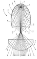
図6は、光源ユニット10から前方へ照射されるビームにより灯具前方25mの位置に配置された仮想鉛直スクリーン上に形成されるロービーム配光パターンP(L)を、光源ユニット10と共にその背面側から透視的に示す図である。
【0049】
図示のように、ロービーム配光パターンP(L)は、基本配光パターンPoと付加配光パターンPaとの合成配光パターンとして形成される。
【0050】
基本配光パターンPoは、第1反射面14aからの反射光(ロービーム照射光Bo)により形成される左配光パターンであって、その上端縁に水平および斜めカットオフラインCL1、CL2を有している。水平カットオフラインCL1は、出射端面14cの水平カットオフ形成部14c1の反転像としてH−V(灯具前方真正面)の右側(対向車線側)に形成され、斜めカットオフラインCL2は、出射端面14cの斜めカットオフ形成部14c2の反転像としてH−Vの左側(自車線側)に形成される。これら水平カットオフラインCL1と斜めカットオフラインCL2との交点(エルボ点)Eの位置は、H−Vのやや下方位置(0.5〜0.6°程度下方位置)に設定されている。そして、この基本配光パターンPoにより、車両前方路面における遠方領域の視認性を確保するようになっている。
【0051】
一方、付加配光パターンPaは、第2反射面14bからの反射光(付加照射光Ba)により形成される配光パターンであって、基本配光パターンPoの下半部と重複して左右方向に幅広く拡散するように形成される。そして、この付加配光パターンPaにより、車両前方路面における近距離領域の視認性を確保するようになっている。
【0052】
本実施形態に係る車両用灯具100は、光源ユニット10を10個備えているので、この車両用灯具100全体としては、各光源ユニット10からの照射ビームによって形成されるロービーム配光パターンP(L)が10重に重畳された合成配光パターンでビーム照射を行うこととなる。そしてこれによりヘッドランプのロービーム照射に必要な明るさを十分に確保するようになっている。
【0053】
以上詳述したように、本実施形態に係る光源ユニット10は、その車両前後方向に延びる光軸Ax上にLED12が鉛直方向上方へ向けて配置されるとともに、このLED12の上方側に、該LED12からの光を前方へ向けて光軸Ax寄りに集光反射させる第1反射面14aを有するリフレクタ14が設けられているが、このリフレクタ14はLED12を覆うように形成された透光ブロック16の表面に反射面処理が施されてなり、その表面の一部が第1反射面14aとして構成されているので、該第1反射面14aの内面反射を利用することができ、これにより従来のプロジェクタ型の車両用灯具に用いられているリフレクタに比して、リフレクタ14を大幅に小型化することができる。
【0054】
その際、光源としてLED12が用いられているので、光源を略点光源として取り扱うことが可能となり、このためリフレクタ14を小型化した場合においても、リフレクタ14によりLED12からの光を適正に反射制御することが可能となる。しかも、このLED12は、光源ユニット10の光軸Axと略直交する方向へ向けて配置されているので、LED12から出射される光の大半を第1反射面14aからの反射光として利用することができる。
【0055】
また、光源としてLED12が用いられているので、従来のように放電バルブやハロゲンバルブ等を取り付けるための大きなスペースを確保する必要がなく、この点においてもリフレクタ14を小型化することができる。しかも、LED12の採用により、発熱の影響をほとんど考慮する必要がなくなるので、この点においてもリフレクタ14を小型化することができる。
【0056】
したがって、本実施形態に係る光源ユニット10を車両用灯具に用いることにより、該車両用灯具の大幅な小型化を図ることができる。
【0057】
本実施形態に係る車両用灯具100は、ロービーム照射用のヘッドランプであり、そのロービーム照射に必要な明るさが十分に確保されるよう、光源ユニット10を10個備えた構成となっているが、その際、各光源ユニット10の配置を任意に設定することが容易に可能であるので、車両用灯具としての形状自由度を高めることができる。
【0058】
特に本実施形態においては、リフレクタ14がLED12を覆うように形成された透光ブロック16で構成されているので、少ない部品点数で光源ユニット10を構成することができる。
【0059】
また一般に、リフレクタを小型化した場合には光源とリフレクタの反射面との位置関係に高い精度が要求されるが、本実施形態においては、リフレクタ14がLED12を覆うように形成された透光ブロック16で構成されているので、LED12と第1反射面14aとの位置関係精度を十分に高めることができる。
【0060】
さらに、リフレクタ14がLED12を覆うように形成された透光ブロック16で構成されていることにより、光源ユニット10としての強度を高めることができ、振動や衝撃により光源の位置ズレが発生して灯具配光が乱れてしまうのを効果的に抑制することができる。
【0061】
なお本実施形態においては、リフレクタ14の第1反射面14aが、LED12から該第1反射面14aまでの鉛直方向の距離Lが10mm程度の値となるように形成されているものとして説明したが、この距離Lを10mmよりも多少大きい値(すなわち、20mm以下、好ましくは16mm以下、さらに好ましくは12mm以下)に設定した場合においても、従来のプロジェクタ型の車両用灯具に用いられているリフレクタに比して、リフレクタ14を大幅に小型化することができる。
【0062】
本実施形態においては、リフレクタ14の表面における第1反射面14aの前端部の上部が、該第1反射面14aから前方へ向けて光軸Ax寄りに傾斜するようにして延びる第2反射面14bとして構成されているので、その分だけさらにリフレクタ14の利用立体角を増大させることができ、これにより光源ユニット10としての利用光束を一層増大させることができる。
【0063】
また本実施形態においては、透光ブロック16の出射端面14cが、光軸Axを中心とする中心角195°の略扇形に形成されているので、光源ユニット10からのビーム照射により、水平および斜めカットオフラインCL1、CL2を有するロービーム配光パターンP(L)を形成することができる。
【0064】
その際、透光ブロック16の表面における出射端面14cの近傍部位には、該出射端面14cから後方へ延びる平面部が形成されており、この平面部が第1反射面14aからの反射光を上方側へ反射させる第3反射面14dとして構成されているので、本来は出射端面14cまで到達しない光を出射端面14cまで到達させて、これをビーム照射用として有効に活用することができ、これにより光源ユニット10としての利用光束をより一層増大させることができる。
【0065】
さらに本実施形態に係る光源ユニット10は、投影レンズ18を備えた構成となっているので、車両用灯具100の組付けを行う前の段階で投影レンズ18とリフレクタ14との位置関係を精度良く設定しておくことができ、これにより車両用灯具100の組付けを容易に行うことができる。
【0066】
本実施形態に係る光源ユニット10においては、LED12が鉛直方向上方へ向けて配置された構成となっているが、図7に示すように、LED12を鉛直方向上方に対して光軸Ax回りに右方向へ15°回転した方向へ向けて配置することも可能である。このようにした場合には、次のような作用効果を得ることができる。
【0067】
すなわち、一般に、LEDから出射される光の配光曲線は、該LEDの正面方向が最大光度で正面方向からの角度が大きくなるに従って光度が減少する光度分布を有している。そこで、LED12を上述したように15°回転した配置とすることにより、基本配光パターンPoにおける斜めカットオフラインCL2の下方領域(図7において2点鎖線で示す領域)Aを明るく照射することができる。そしてこれにより、ロービーム配光パターンP(L)を一層遠方視認性に優れたものとすることができる。
【0068】
なお本実施形態においては、水平および斜めカットオフラインCL1、CL2を有するロービーム配光パターンP(L)を形成するために、透光ブロック16の出射端面14cの下端縁が水平カットオフ形成面14a1および斜めカットオフ形成面14a2からなるものとして説明したが、これ以外のカットオフライン(例えば左右段違いの段付き水平カットオフラインからなるもの)を有するロービーム配光パターンを形成するために、出射端面14cの下端縁を本実施形態とは異なる形状に設定するようにした場合においても、本実施形態と同様の構成を採用することにより本実施形態と同様の作用効果を得ることができる。
【0069】
次に上記実施形態の第1の変形例について説明する。
【0070】
図8は、本変形例に係る光源ユニット10Aを示す側断面図である。
【0071】
図示のように、本変形例に係る光源ユニット10Aは、その透光ブロック16Aおよび投影レンズ18Aの構成が、上記実施形態の透光ブロック16および投影レンズ18と異なっているが、それ以外の構成については上記実施形態と同様である。
【0072】
透光ブロック16Aは、その出射端面14cの形状については上記実施形態の透光ブロック16(図中2点鎖線で示す)と同様であるが、その第3反射面14Adが出射端面14cから後方へ向けてやや上向きに傾斜するようにして延びている。この上向き傾斜角度αは、例えば1〜10°程度の範囲内の適当な値に設定されている。
【0073】
第3反射面14Adをこのように形成することにより、該第3反射面14Adからの反射光の上向き角度は、上記実施形態の場合(図中2点鎖線で反射光の光路を示す)に比して角度2α分だけ小さくなり、これにより出射端面14cからの偏向出射光もこれに対応する角度分(2α対応分)だけ小さくなる。したがって、第3反射面14Adからの反射光が投影レンズ18Aへ入射する位置は、上記実施形態の場合に比して低い位置になる。
【0074】
このため、本変形例における投影レンズ18Aは、上記実施形態の投影レンズ18(図中2点鎖線で示す)において第3反射面14Adからの反射光が入射しない部分となる上端部が切り取られた形状となっている。
【0075】
本変形例の構成を採用することにより、投影レンズ18Aの上下幅を小さくすることができ、これにより光源ユニット10Aを一層小型化することができる。
【0076】
次に上記実施形態の第2の変形例について説明する。
【0077】
図9は、本変形例に係る車両用灯具100Aを示す正面図である。
【0078】
この車両用灯具100Aも、上記実施形態の車両用灯具100と同様、ロービーム照射用のヘッドランプであって、10個の光源ユニットが略横一列で設けられた構成となっているが、これら光源ユニットが複数種類の光源ユニットの組合せで構成されている点で、上記実施形態と異なっている。
【0079】
すなわち、10個の光源ユニットのうち4個は、上記実施形態と同様の光源ユニット10であるが、残り6個はホットゾーン(高光度領域)形成用の光源ユニットであって、そのうち3個が水平カットオフ形成用の光源ユニット10Bであり、残り3個が斜めカットオフ形成用の光源ユニット10Cである。
【0080】
水平カットオフ形成用の光源ユニット10Bは、その基本的構成は光源ユニット10と同様であるが、次の点で異なっている。すなわち、この光源ユニット10Bにおいては、透光ブロック16Bの第3反射面14Bd全体が、光軸Axから左右両方向へ水平に延びる水平カットオフ形成面として形成されている。また、この光源ユニット10Bにおいては、投影レンズ18Bとして光源ユニット10の投影レンズ18よりもバックフォーカル長が長いレンズが用いられている。
【0081】
一方、斜めカットオフ形成用の光源ユニット10Cも、その基本的構成は光源ユニット10と同様であるが、次の点で異なっている。すなわち、この光源ユニット10Cにおいては、透光ブロック16Cの第3反射面14Cd全体が、光軸Axから左方向へ斜め15°上向きに延びるとともに右方向へ斜め15°下向きに延びる斜めカットオフ形成面として形成されており、また、この光源ユニット10Cにおいては、その投影レンズ18Cとして光源ユニット10Bの投影レンズ18Bよりもさらにバックフォーカル長が長いレンズが用いられている。なお、この光源ユニット10CのLED12は、鉛直方向上方に対して光軸Ax回りに右方向へ15°回転した方向へ向けて配置されている(図11参照)。
【0082】
図10は、光源ユニット10Bから前方へ照射されるビームにより灯具前方25mの位置に配置された仮想鉛直スクリーン上に形成される水平カットオフ形成用配光パターンP1を、光源ユニット10Bと共にその背面側から透視的に示す図である。
【0083】
図示のように、水平カットオフ形成用配光パターンP1は、基本配光パターンP1oと付加配光パターンP1aとの合成配光パターンとして形成される。
【0084】
基本配光パターンP1oは、第1反射面14Baからの反射光(ホットゾーン形成用照射光B1o)により形成される配光パターンであって、その上端縁に水平カットオフラインCL1を有している。この水平カットオフラインCL1は、光源ユニット10により形成される水平カットオフラインCL1と同じ高さに形成されるようになっている。
【0085】
光源ユニット10Bの投影レンズ18Bは、光源ユニット10の投影レンズ18よりもバックフォーカル長が長いので、基本配光パターンP1oは、光源ユニット10により形成される基本配光パターンPoに比して、小さくて明るい配光パターンとなる。そしてこれにより、基本配光パターンP1oは水平カットオフラインCL1に沿ったホットゾーンを形成し、車両前方路面における遠方領域の視認性を十分に高めるようになっている。
【0086】
一方、付加配光パターンP1aは、第2反射面14bからの反射光(付加照射光B1a)により形成される配光パターンであって、基本配光パターンP1oの下半部と重複して左右方向に幅広く拡散するように形成される。なお、この付加配光パターンP1aについても、投影レンズ18Bのバックフォーカル長が長い分だけ、光源ユニット10により形成される付加配光パターンPaよりも小さい配光パターンとなっている。そして、この付加配光パターンP1aにより、車両前方路面における基本配光パターンP1oの手前側領域の視認性を確保するようになっている。
【0087】
図11は、光源ユニット10Cから前方へ照射されるビームにより灯具前方25mの位置に配置された仮想鉛直スクリーン上に形成される斜めカットオフ形成用配光パターンP2を、光源ユニット10Cと共にその背面側から透視的に示す図である。
【0088】
図示のように、斜めカットオフ形成用配光パターンP2は、基本配光パターンP2oと付加配光パターンP2aとの合成配光パターンとして形成される。
【0089】
基本配光パターンP2oは、第1反射面14aからの反射光(ホットゾーン形成用照射光B2o)により形成される配光パターンであって、その上端縁に斜めカットオフラインCL2を有している。この斜めカットオフラインCL2は、光源ユニット10により形成される斜めカットオフラインCL2と同じ高さに形成されるようになっている。
【0090】
光源ユニット10Cの投影レンズ18Cは、光源ユニット10Bの投影レンズ18Bよりもさらにバックフォーカル長が長いので、基本配光パターンP2oは、光源ユニット10Bにより形成される基本配光パターンP1oに比して、さらに小さくて明るい配光パターンとなる。そしてこれにより、基本配光パターンP2oは斜めカットオフラインCL2に沿ったホットゾーンを形成し、車両前方路面における遠方領域の視認性を十分に高めるようになっている。
【0091】
一方、付加配光パターンP2aは、第2反射面14bからの反射光(付加照射光B2a)により形成される配光パターンであって、基本配光パターンP2oの下半部と重複して左右方向に幅広く拡散するように形成される。なお、この付加配光パターンP2aについても、投影レンズ18Cのバックフォーカル長が長い分だけ、光源ユニット10Bにより形成される付加配光パターンP1aよりもさらに小さい配光パターンとなっている。そして、この付加配光パターンP2aにより、車両前方路面における基本配光パターンP2oの手前側領域の視認性を確保するようになっている。
【0092】
図12は、本変形例に係る車両用灯具100Aから前方へ照射されるビームにより灯具前方25mの位置に配置された仮想鉛直スクリーン上に形成される合成ロービーム配光パターンPΣ(L)を透視的に示す図である。
【0093】
図示のように、この合成ロービーム配光パターンPΣ(L)は、4個の光源ユニット10の各々からの照射ビームによって形成されるロービーム配光パターンP(L)が4重に重畳され、3個の光源ユニット10Bからの照射ビームによって形成される水平カットオフ形成用配光パターンP1が3重に重畳され、3個の光源ユニット10Cからの照射ビームによって形成される斜めカットオフ形成用配光パターンP2が3重に重畳された配光パターンとなっている。
【0094】
本変形例に係る車両用灯具100Aを採用することにより、エルボ点Eの近傍にホットゾーンが形成された合成ロービーム配光パターンPΣ(L)を得ることができ、これにより上記実施形態に比して一層遠方視認性に優れた配光パターンでロービーム照射を行うことができる。
【0095】
なお本変形例においては、3種類の光源ユニット10、10B、10Cの組合せで構成された車両用灯具100Aについて説明したが、さらに多くの種類の光源ユニットの組合せで車両用灯具を構成することも可能であり、このようにすることにより一層きめ細かく配光制御を行うことが可能となる。
【0096】
次に上記実施形態の第3の変形例について説明する。
【0097】
図13は、本変形例に係る光源ユニット30を示す側断面図である。
【0098】
図示のように、本変形例に係る光源ユニット30は、ハイビーム配光パターンでビーム照射を行うための光源ユニットとして構成されている。
【0099】
すなわち、本変形例に係る光源ユニット30においても、そのリフレクタ34はLED12を覆うように形成された透光ブロック36の表面に反射面処理が施されてなっているが、本変形例においては、透光ブロック36の出射端面34cが、上記実施形態の透光ブロック16の出射端面14cのように光軸Axを中心とする中心角195°の略扇形には形成されておらず、該出射端面34cの下端縁は上記実施形態の出射端面14cの下端縁よりもかなり下方に位置している。
【0100】
また、透光ブロック36の下端部には、上記実施形態のような第3反射面14dに代えて、前方へ向けて下向きに傾斜するようにして延びる第4反射面34dが形成されている。
【0101】
さらに、本変形例のリフレクタ34は、その第1反射面34aの構成については上記実施形態の第1反射面14aと同様であるが、第1反射面34aの前端部の上部に形成された第2反射面34bについては、その下向き傾斜角度が上記実施形態の第2反射面14bに比して大きい値に設定されている。
【0102】
本変形例においては、透光ブロック36の出射端面34cの下端縁が、上記実施形態の出射端面14cの下端縁よりもかなり下方に位置しているので、第1反射面34aで反射したLED12からの光は、すべてそのまま出射端面34cに到達し、この出射端面34cから偏向出射した光は、投影レンズ18を介して前方へ上向き光および下向き光を含むハイビーム照射光Bo´として出射する。
【0103】
また本変形例においては、第2反射面34bで反射したLED12からの光は、第4反射面34dで再度反射して出射端面34cに到達し、この出射端面34cから偏向出射した光は、投影レンズ18を介して前方へ上向き光および下向き光を含む付加照射光Ba´として出射する。この付加照射光Ba´の照射方向は、第4反射面34dでの反射位置によって異なったものとなるが、全体としてはハイビーム照射光Bo´よりも上向きの光として左右方向に幅広く照射される。
【0104】
図14は、光源ユニット30から前方へ照射されるビームにより灯具前方25mの位置に配置された仮想鉛直スクリーン上に形成されるハイビーム配光パターンP(H)を、光源ユニット30と共にその背面側から透視的に示す図である。
【0105】
図示のように、ハイビーム配光パターンP(H)は、基本配光パターンPo´と付加配光パターンPa´との合成配光パターンとして形成される。
【0106】
基本配光パターンPo´は、第1反射面34aからの反射光(ハイビーム照射光Bo´)により形成される配光パターンであり、上記実施形態の基本配光パターンPoを上方に延長形成したような形状を有している。そして、この基本配光パターンPo´により、略H−Vを中心にして車両前方を幅広く照射するようになっている。
【0107】
一方、付加配光パターンPa´は、第4反射面34dからの反射光(付加照射光Ba´)により形成される配光パターンであって、基本配光パターンPo´の上半部と重複して左右方向に幅広く拡散するように形成される。そして、この付加配光パターンPa´により、車両前方をさらに幅広く照射するようになっている。
【0108】
本変形例に係る光源ユニット30と上記実施形態に係る光源ユニット10とを適宜組み合わせて用いることにより、ロービーム照射機能とハイビーム照射機能とを兼ね備えたヘッドランプを構成することも可能である。
【0109】
なお、上記実施形態および各変形例においては、リフレクタ14、34を構成する透光ブロック16、16B、16C、36がLED12とは別体で構成されているが、一般にLEDにはその発光部を覆う封止樹脂部が設けられているので、この封止樹脂部の形状を大きくすることにより透光ブロック16、16B、16C、36を構成することも可能である。
【0110】
上記実施形態および各変形例においては、光源ユニット10、10A、10B、10C、30がヘッドランプに用いられる場合について説明したが、これら光源ユニット10、10A、10B、10C、30を、フォグランプ、ベンディングランプ等に用いることも可能であり、このようにした場合においても上記実施形態および変形例と同様の作用効果を得ることができる。
【図面の簡単な説明】
【図1】本願発明の一実施形態に係る光源ユニットを備えた車両用灯具を示す正面図
【図2】上記光源ユニットを示す正面図
【図3】上記光源ユニットを示す側断面図
【図4】上記光源ユニットを示す平断面図
【図5】上記光源ユニットから照射されるビームの光路を詳細に示す側断面図
【図6】上記光源ユニットから前方へ照射されるビームにより灯具前方25mの位置に配置された仮想鉛直スクリーン上に形成される配光パターンを、光源ユニットと共にその背面側から透視的に示す図
【図7】上記実施形態におけるLED配置の変形例を示す、図6と同様の図
【図8】上記実施形態の第1の変形例を示す、図5と同様の図
【図9】上記実施形態の第2の変形例を示す、図1と同様の図
【図10】上記第2の変形例を構成する水平カットオフ形成用の光源ユニットから前方へ照射されるビームにより上記仮想鉛直スクリーン上に形成される配光パターンを、光源ユニットと共にその背面側から透視的に示す図
【図11】上記第2の変形例を構成する斜めカットオフ形成用の光源ユニットから前方へ照射されるビームにより上記仮想鉛直スクリーン上に形成される配光パターンを、光源ユニットと共にその背面側から透視的に示す図
【図12】上記第2の変形例に係る車両用灯具から前方へ照射されるビームにより上記仮想鉛直スクリーン上に形成される合成ロービーム配光パターンを透視的に示す図
【図13】上記実施形態の第3の変形例を示す、図5と同様の図
【図14】上記第3の変形例を示す、図6と同様の図
【符号の説明】
10、10A、10B、10C、30 光源ユニット
12 LED(半導体発光素子)
14、34 リフレクタ
14a、34a 第1反射面
14b、34b 第2反射面
14c、34c 出射端面
14c1 水平カットオフ形成部
14c2 斜めカットオフ形成部
14d、14Ad、14Bd、14Cd 第3反射面(光制御部)
16、16A、16B、16C、36 透光ブロック
18、18A、18B 投影レンズ
20 基板
34d 第4反射面
100、100A 車両用灯具
102 透明カバー
104 ランプボディ
Ax 光軸
Bo ロービーム照射光
Bo´ ハイビーム照射光
B1o、B2o ホットゾーン形成用照射光
Ba、Ba´、B1a、B2a 付加照射光
CL1 水平カットオフライン
CL2 斜めカットオフライン
E エルボ点
F1 第1焦点
F2 第2焦点
L LEDから第1反射面までの鉛直方向の距離
P(H) ハイビーム配光パターン
P(L) ロービーム配光パターン
Po、Po´、P1o、P2o 基本配光パターン
Pa、Pa´、P1a、P2a 付加配光パターン
P1 水平カットオフ形成用配光パターン
P2 斜めカットオフ形成用配光パターン
PΣ(L) 合成ロービーム配光パターン[0001]
BACKGROUND OF THE INVENTION
The present invention relates to a light source unit used in a vehicular lamp.
[0002]
[Prior art]
Conventionally, as a vehicle lamp such as a headlamp, a so-called projector type is known as one of the lamp types.
[0003]
This projector-type vehicular lamp is configured to project and reflect light from a light source arranged on an optical axis toward the front by a reflector toward the optical axis, and this reflected light is provided in front of the reflector. It is comprised so that it may irradiate to a lamp front via.
[0004]
By adopting such a projector-type vehicular lamp, it is possible to reduce the size of the lamp as compared with a so-called parabolic vehicular lamp.
[0005]
[Problems to be solved by the invention]
However, the conventional projector-type vehicular lamp has the following problems because the discharge light emitting part of the discharge bulb, the filament of the halogen bulb, and the like are used as the light source.
[0006]
That is, since the light source has a certain size as a line light source, it is necessary to secure a certain size for the reflector in order to appropriately reflect and control the light from the light source. In addition, since it is necessary to secure a space for mounting a discharge bulb, a halogen bulb, etc., it is necessary to set the reflector size to a certain extent also in this respect. Furthermore, since the light source generates heat, it is necessary to secure a reflector size that takes into account the influence of the heat.
[0007]
For this reason, the conventional projector-type vehicle lamp has a problem that the lamp cannot be significantly reduced in size.
[0008]
JP-A-2002-50214, JP-A-2001-332104, and JP-A-9-330604 describe a vehicular lamp using an LED that is a small light source. Japanese Patent Application Laid-Open No. 2002-42520 and Japanese Patent Application Laid-Open No. 2000-76889 describe a light emitting device in which a reflecting surface is arranged near an LED.
[0009]
This invention is made | formed in view of such a situation, Comprising: It aims at providing the light source unit which can achieve size reduction of a vehicle lamp significantly.
[0010]
[Means for Solving the Problems]
The present invention employs a semiconductor light emitting element as a light source, and devise the arrangement and the configuration of the reflector to achieve the above object.
[0011]
That is, the light source unit according to the present invention is
A light source unit used for a vehicular lamp,
A semiconductor light emitting element disposed on a light axis of the light source unit in a predetermined direction substantially orthogonal to the optical axis; and provided on the front side in the predetermined direction with respect to the semiconductor light emitting element; A reflector having a first reflecting surface that condenses and reflects light toward the front of the optical axis toward the front in the optical axis direction;
The reflector is provided with a reflecting surface treatment on a surface of a light transmitting block formed so as to cover the semiconductor light emitting element, and a part of the surface of the light transmitting block is configured as the first reflecting surface.And
An exit end surface for emitting the reflected light from the first reflecting surface on the surface of the light transmitting block forward from the light transmitting block in the optical axis direction is formed in a substantially fan shape centered on the optical axis,
A projection lens is provided at a predetermined position on the front side in the optical axis direction with respect to the reflector.It is characterized by that.
[0012]
The “vehicle lamp” is not limited to a specific type of vehicle lamp, and for example, a headlamp, a fog lamp, a bending lamp, or the like can be employed.
[0013]
The “optical axis of the light source unit” may be set to extend in the vehicle front-rear direction, or may be set to extend in other directions.
[0014]
The “predetermined direction” is not limited to a specific direction as long as it is a direction substantially orthogonal to the optical axis of the light source unit. For example, it can be set upward, laterally, downward, or the like.
[0015]
The type of the “semiconductor light emitting element” is not particularly limited, and for example, an LED (light emitting diode) or an LD (semiconductor laser) can be employed.
[0016]
The “translucent block” is not particularly limited as long as it is a translucent block. For example, a translucent block made of a transparent synthetic resin or a glass is employed. Is possible. In addition, the “surface” of the translucent block is a “surface” as an expression focusing on the inner surface reflection function of the translucent block, and it is not always necessary that the “surface” is an outer surface. A configuration in which a protective coating is formed on the outer peripheral side of the “surface” or a configuration in which a covering member is provided may be employed. In this case, the specific configuration of the “cover member” is not particularly limited, and may be a member made of the same material as the “translucent block”, for example.
[0017]
[Effects of the invention]
As shown in the above configuration, in the light source unit according to the present invention, the semiconductor light emitting element is arranged on the optical axis in a predetermined direction substantially orthogonal to the optical axis, and the predetermined direction with respect to the semiconductor light emitting element. A reflector having a first reflecting surface that condenses and reflects light from the semiconductor light emitting element toward the front in the optical axis direction and near the optical axis is provided on the front side. The reflector covers the semiconductor light emitting element. Since the surface of the translucent block formed on the surface is subjected to a reflection surface treatment, and a part of the surface is configured as the first reflection surface, it is possible to use internal reflection of the first reflection surface. Thus, the reflector can be greatly reduced in size as compared with the reflector used in the conventional projector-type vehicle lamp.
[0018]
At this time, since the semiconductor light emitting element is used as the light source, it becomes possible to handle the light source as a substantially point light source. Therefore, even when the reflector is miniaturized, the light from the semiconductor light emitting element is appropriately transmitted by the reflector. It is possible to control reflection. In addition, since the semiconductor light emitting element is arranged in a predetermined direction substantially orthogonal to the optical axis of the light source unit, most of the light emitted from the semiconductor light emitting element is used as reflected light from the first reflecting surface. be able to.
[0019]
In addition, since a semiconductor light emitting element is used as a light source, it is not necessary to secure a large space for mounting a discharge bulb, a halogen bulb or the like as in the prior art, and the reflector can be downsized in this respect as well. In addition, the adoption of the semiconductor light-emitting element eliminates the need to consider the effect of heat generation, so that the reflector can be downsized in this respect as well.
[0020]
Therefore, by using the light source unit according to the present invention for a vehicular lamp, the vehicular lamp can be significantly reduced in size.
[0021]
In particular, in the present invention, since the reflector is composed of a light transmitting block formed so as to cover the semiconductor light emitting element, the light source unit can be configured with a small number of parts.
[0022]
In general, when the reflector is miniaturized, high accuracy is required for the positional relationship between the light source and the reflecting surface of the reflector. In the present invention, however, the translucent block is formed so that the reflector covers the semiconductor light emitting element. Thus, the positional relationship accuracy between the semiconductor light emitting element and the first reflecting surface can be sufficiently increased.
[0023]
Furthermore, since the reflector is composed of a light-transmitting block formed so as to cover the semiconductor light emitting element, the strength as the light source unit can be increased, and the position of the light source is shifted due to vibration or impact, and the lamp is arranged. It is possible to effectively prevent the light from being disturbed.
[0024]
When the light source unit according to the present invention is used for a vehicle lamp, only one light source unit or a plurality of light source units may be used. In the latter case, the brightness of the vehicular lamp can be increased by the number of light source units. At that time, it is possible to easily set the arrangement of the respective light source units, so that the degree of freedom of shape as a vehicular lamp can be increased.
[0025]
In the above configuration, if the first reflecting surface is formed so that the distance in the predetermined direction from the semiconductor light emitting element to the first reflecting surface is 20 mm or less, the reflector can be sufficiently miniaturized.
[0026]
Further, in the configuration, if the front end portion in the optical axis direction of the first reflecting surface on the surface of the light transmitting block is configured as a second reflecting surface extending so as to incline toward the front in the optical axis direction, the portion corresponding thereto. In addition, it is possible to further increase the use solid angle of the reflector, thereby further increasing the use light flux as the light source unit.
[0027]
In the present inventionAn exit end face for emitting the reflected light from the first reflecting surface to the front in the optical axis direction from the light transmitting block on the surface of the light transmitting blockButFormed in a generally fan shape centered on the optical axisBecauseBy the beam irradiation from the light source unit, it becomes possible to form a light distribution pattern having a cut-off line such as a low beam light distribution pattern of a headlamp, for example.
[0028]
At this time, a flat portion extending rearward in the optical axis direction from the emission end surface is formed in the vicinity of the emission end surface on the surface of the translucent block, and the reflected light from the first reflection surface is directed to the predetermined direction side. If it is configured as a third reflecting surface to be reflected, light that does not originally reach the exit end face can be made to reach the exit end face, and this can be used effectively for beam irradiation, thereby providing a light source unit. The used light flux can be further increased.
[0030]
DETAILED DESCRIPTION OF THE INVENTION
Hereinafter, embodiments of the present invention will be described with reference to the drawings.
[0031]
FIG. 1 is a front view showing a
[0032]
The
[0033]
Each of these
[0034]
2 is a front view showing one
[0035]
As shown in these drawings, the
[0036]
The
[0037]
In the
[0038]
The first reflecting
[0039]
The front end portion of the first reflecting
[0040]
At the front end portion of the
[0041]
A flat portion extending rearward from the
[0042]
A
[0043]
The
[0044]
The
[0045]
FIG. 5 is a side sectional view showing in detail the optical path of the beam emitted from the
[0046]
As shown in the drawing, the light reflected from the first reflecting
[0047]
On the other hand, the light from the
[0048]
FIG. 6 shows a low beam distribution pattern P (L) formed on a virtual vertical screen arranged at a position 25 m ahead of the lamp by a beam irradiated forward from the
[0049]
As illustrated, the low beam light distribution pattern P (L) is formed as a combined light distribution pattern of the basic light distribution pattern Po and the additional light distribution pattern Pa.
[0050]
The basic light distribution pattern Po is a left light distribution pattern formed by reflected light (low beam irradiation light Bo) from the first reflecting
[0051]
On the other hand, the additional light distribution pattern Pa is a light distribution pattern formed by the reflected light (additional irradiation light Ba) from the second reflecting
[0052]
Since the
[0053]
As described above in detail, in the
[0054]
At this time, since the
[0055]
Further, since the
[0056]
Therefore, by using the
[0057]
The
[0058]
In particular, in the present embodiment, since the
[0059]
In general, when the reflector is miniaturized, a high accuracy is required for the positional relationship between the light source and the reflecting surface of the reflector. In the present embodiment, the translucent block is formed so that the
[0060]
Further, since the
[0061]
In the present embodiment, the first reflecting
[0062]
In the present embodiment, the upper part of the front end portion of the first reflecting
[0063]
In the present embodiment, since the
[0064]
At this time, a planar portion extending rearward from the
[0065]
Furthermore, since the
[0066]
The
[0067]
That is, in general, the light distribution curve of light emitted from an LED has a luminous intensity distribution in which the luminous intensity decreases as the front direction of the LED is maximum luminous intensity and the angle from the front direction increases. Therefore, by arranging the
[0068]
In this embodiment, in order to form the low beam distribution pattern P (L) having the horizontal and oblique cutoff lines CL1 and CL2, the lower end edge of the
[0069]
Next, a first modification of the above embodiment will be described.
[0070]
FIG. 8 is a side sectional view showing a
[0071]
As shown in the figure, the
[0072]
The shape of the light
[0073]
By forming the third reflecting surface 14Ad in this way, the upward angle of the reflected light from the third reflecting surface 14Ad is compared with the case of the above embodiment (the optical path of the reflected light is indicated by a two-dot chain line in the figure). As a result, the angle is reduced by the angle 2α, and the deflected emitted light from the
[0074]
For this reason, the
[0075]
By adopting the configuration of this modification, the vertical width of the
[0076]
Next, a second modification of the above embodiment will be described.
[0077]
FIG. 9 is a front view showing a
[0078]
The
[0079]
That is, four of the ten light source units are the same
[0080]
The
[0081]
On the other hand, the
[0082]
FIG. 10 shows a light distribution pattern P1 for forming a horizontal cut-off formed on a virtual vertical screen arranged at a position 25 m ahead of the lamp by a beam irradiated forward from the
[0083]
As illustrated, the horizontal cut-off formation light distribution pattern P1 is formed as a combined light distribution pattern of the basic light distribution pattern P1o and the additional light distribution pattern P1a.
[0084]
The basic light distribution pattern P1o is a light distribution pattern formed by the reflected light from the first reflecting surface 14Ba (hot zone forming irradiation light B1o), and has a horizontal cutoff line CL1 at the upper edge thereof. The horizontal cutoff line CL1 is formed at the same height as the horizontal cutoff line CL1 formed by the
[0085]
Since the
[0086]
On the other hand, the additional light distribution pattern P1a is a light distribution pattern formed by the reflected light (additional irradiation light B1a) from the second reflecting
[0087]
FIG. 11 shows a light distribution pattern P2 for forming an oblique cut-off formed on a virtual vertical screen disposed at a position 25 m ahead of the lamp by a beam irradiated forward from the
[0088]
As illustrated, the oblique cut-off formation light distribution pattern P2 is formed as a combined light distribution pattern of the basic light distribution pattern P2o and the additional light distribution pattern P2a.
[0089]
The basic light distribution pattern P2o is a light distribution pattern formed by reflected light (hot zone forming irradiation light B2o) from the first reflecting
[0090]
Since the
[0091]
On the other hand, the additional light distribution pattern P2a is a light distribution pattern formed by the reflected light (additional irradiation light B2a) from the second reflecting
[0092]
FIG. 12 is a perspective view of a synthetic low beam light distribution pattern PΣ (L) formed on a virtual vertical screen arranged at a position 25 m ahead of the lamp by a beam irradiated forward from the
[0093]
As shown in the figure, this combined low beam light distribution pattern PΣ (L) is formed by superposing four low beam light distribution patterns P (L) formed by irradiation beams from each of the four
[0094]
By adopting the
[0095]
In addition, in this modification, although the
[0096]
Next, a third modification of the above embodiment will be described.
[0097]
FIG. 13 is a side sectional view showing the
[0098]
As shown in the figure, the
[0099]
That is, also in the
[0100]
Further, at the lower end portion of the
[0101]
Further, the
[0102]
In the present modification, the lower end edge of the light emitting
[0103]
In this modification, the light from the
[0104]
FIG. 14 shows a high beam light distribution pattern P (H) formed on a virtual vertical screen arranged at a position 25 m ahead of the lamp by a beam irradiated forward from the
[0105]
As illustrated, the high beam light distribution pattern P (H) is formed as a combined light distribution pattern of the basic light distribution pattern Po ′ and the additional light distribution pattern Pa ′.
[0106]
The basic light distribution pattern Po ′ is a light distribution pattern formed by reflected light (high beam irradiation light Bo ′) from the first reflecting
[0107]
On the other hand, the additional light distribution pattern Pa ′ is a light distribution pattern formed by the reflected light (additional irradiation light Ba ′) from the fourth reflecting
[0108]
A headlamp having both a low beam irradiation function and a high beam irradiation function can be configured by appropriately combining the
[0109]
In the above-described embodiment and each modification, the light-transmitting
[0110]
In the above-described embodiment and each modified example, the case where the
[Brief description of the drawings]
FIG. 1 is a front view showing a vehicular lamp provided with a light source unit according to an embodiment of the present invention.
FIG. 2 is a front view showing the light source unit.
FIG. 3 is a side sectional view showing the light source unit.
FIG. 4 is a plan sectional view showing the light source unit.
FIG. 5 is a side sectional view showing in detail an optical path of a beam emitted from the light source unit.
FIG. 6 is a perspective view showing a light distribution pattern formed on a virtual vertical screen arranged at a position 25 m ahead of a lamp by a beam irradiated forward from the light source unit together with the light source unit from the back side thereof.
FIG. 7 is a view similar to FIG. 6, showing a modification of the LED arrangement in the embodiment.
FIG. 8 is a view similar to FIG. 5, showing a first modification of the embodiment.
FIG. 9 is a view similar to FIG. 1, showing a second modification of the embodiment.
FIG. 10 shows a light distribution pattern formed on the virtual vertical screen by a beam irradiated forward from a light source unit for forming a horizontal cut-off constituting the second modification, together with the light source unit, from the back side thereof. Perspective view
FIG. 11 shows a light distribution pattern formed on the virtual vertical screen by a beam irradiated forward from a light source unit for forming an oblique cut-off constituting the second modification, together with the light source unit, from the back side thereof. Perspective view
FIG. 12 is a view perspectively showing a synthetic low beam light distribution pattern formed on the virtual vertical screen by a beam irradiated forward from the vehicular lamp according to the second modified example.
FIG. 13 is a view similar to FIG. 5, showing a third modification of the embodiment.
FIG. 14 is a view similar to FIG. 6, showing the third modification example.
[Explanation of symbols]
10, 10A, 10B, 10C, 30 Light source unit
12 LED (semiconductor light emitting device)
14, 34 Reflector
14a, 34a First reflecting surface
14b, 34b Second reflecting surface
14c, 34c Output end face
14c1 horizontal cut-off forming part
14c2 Diagonal cut-off formation part
14d, 14Ad, 14Bd, 14Cd Third reflecting surface (light control unit)
16, 16A, 16B, 16C, 36 Translucent block
18, 18A, 18B Projection lens
20 substrates
34d Fourth reflecting surface
100, 100A Vehicle lamp
102 Transparent cover
104 Lamp body
Ax optical axis
Bo Low beam irradiation light
Bo 'high beam irradiation light
B1o, B2o Irradiation light for hot zone formation
Ba, Ba ', B1a, B2a Additional irradiation light
CL1 horizontal cut offline
CL2 diagonal cut offline
E Elbow point
F1 first focus
F2 second focus
L Distance in the vertical direction from the LED to the first reflecting surface
P (H) High beam light distribution pattern
P (L) Low beam light distribution pattern
Po, Po ', P1o, P2o Basic light distribution pattern
Pa, Pa ', P1a, P2a Additional light distribution pattern
P1 Light distribution pattern for horizontal cut-off formation
P2 Light distribution pattern for oblique cut-off formation
PΣ (L) Synthetic low beam light distribution pattern
Claims (4)
上記光源ユニットの光軸上に該光軸と略直交する所定方向へ向けて配置された半導体発光素子と、この半導体発光素子に対して上記所定方向前方側に設けられ、該半導体発光素子からの光を上記光軸方向前方へ向けて該光軸寄りに集光反射させる第1反射面を有するリフレクタとを備えてなり、
上記リフレクタが、上記半導体発光素子を覆うように形成された透光ブロックの表面に反射面処理が施されてなり、該透光ブロックの表面の一部が上記第1反射面として構成されており、
上記透光ブロックの表面において上記第1反射面からの反射光を該透光ブロックから上記光軸方向前方へ出射させる出射端面が、上記光軸を中心とする略扇形に形成されており、
上記リフレクタに対して上記光軸方向前方側の所定位置に、投影レンズが設けられている、ことを特徴とする光源ユニット。A light source unit used in a vehicle lamp,
A semiconductor light emitting element disposed on a light axis of the light source unit in a predetermined direction substantially orthogonal to the optical axis; and provided on the front side in the predetermined direction with respect to the semiconductor light emitting element; A reflector having a first reflecting surface that condenses and reflects light toward the front of the optical axis toward the front in the optical axis direction;
The reflector is provided with a reflective surface treatment on the surface of the translucent block formed so as to cover the semiconductor light emitting element, and a part of the surface of the translucent block is configured as the first reflective surface. ,
An exit end surface for emitting the reflected light from the first reflecting surface on the surface of the light transmitting block forward from the light transmitting block in the optical axis direction is formed in a substantially fan shape centered on the optical axis,
A light source unit, wherein a projection lens is provided at a predetermined position on the front side in the optical axis direction with respect to the reflector.
Priority Applications (5)
| Application Number | Priority Date | Filing Date | Title |
|---|---|---|---|
| JP2002120346A JP4068387B2 (en) | 2002-04-23 | 2002-04-23 | Light source unit |
| KR10-2003-0025011A KR100517423B1 (en) | 2002-04-23 | 2003-04-21 | Light unit |
| US10/419,874 US7097334B2 (en) | 2002-04-23 | 2003-04-22 | Light source unit for vehicular lamp |
| CNB031429211A CN1237305C (en) | 2002-04-23 | 2003-04-23 | Light source device |
| EP03008796.9A EP1357333B1 (en) | 2002-04-23 | 2003-04-23 | Light source unit for vehicular lamp |
Applications Claiming Priority (1)
| Application Number | Priority Date | Filing Date | Title |
|---|---|---|---|
| JP2002120346A JP4068387B2 (en) | 2002-04-23 | 2002-04-23 | Light source unit |
Publications (2)
| Publication Number | Publication Date |
|---|---|
| JP2003317514A JP2003317514A (en) | 2003-11-07 |
| JP4068387B2 true JP4068387B2 (en) | 2008-03-26 |
Family
ID=28786760
Family Applications (1)
| Application Number | Title | Priority Date | Filing Date |
|---|---|---|---|
| JP2002120346A Expired - Fee Related JP4068387B2 (en) | 2002-04-23 | 2002-04-23 | Light source unit |
Country Status (5)
| Country | Link |
|---|---|
| US (1) | US7097334B2 (en) |
| EP (1) | EP1357333B1 (en) |
| JP (1) | JP4068387B2 (en) |
| KR (1) | KR100517423B1 (en) |
| CN (1) | CN1237305C (en) |
Cited By (1)
| Publication number | Priority date | Publication date | Assignee | Title |
|---|---|---|---|---|
| US9976719B2 (en) | 2015-10-27 | 2018-05-22 | Stanley Electric Co., Ltd. | Diffusion light distribution optical system and vehicle lighting apparatus |
Families Citing this family (118)
| Publication number | Priority date | Publication date | Assignee | Title |
|---|---|---|---|---|
| JP4047186B2 (en) * | 2003-02-10 | 2008-02-13 | 株式会社小糸製作所 | Vehicle headlamp and optical unit |
| JP4018016B2 (en) * | 2003-03-31 | 2007-12-05 | 株式会社小糸製作所 | Vehicle headlamp |
| JP4002207B2 (en) * | 2003-04-21 | 2007-10-31 | 株式会社小糸製作所 | Vehicle headlamp |
| AT500750B8 (en) * | 2003-06-06 | 2007-02-15 | Zizala Lichtsysteme Gmbh | VEHICLE HEADLIGHTS |
| KR100975057B1 (en) * | 2003-09-17 | 2010-08-11 | 삼성전자주식회사 | Projection display |
| JP4131845B2 (en) * | 2003-09-29 | 2008-08-13 | 株式会社小糸製作所 | Lamp unit and vehicle headlamp |
| US7070301B2 (en) * | 2003-11-04 | 2006-07-04 | 3M Innovative Properties Company | Side reflector for illumination using light emitting diode |
| JP4053489B2 (en) * | 2003-11-04 | 2008-02-27 | 株式会社小糸製作所 | Vehicle headlamp |
| US7090357B2 (en) | 2003-12-23 | 2006-08-15 | 3M Innovative Properties Company | Combined light source for projection display |
| US7201507B2 (en) * | 2003-12-25 | 2007-04-10 | Ichikoh Industries, Ltd. | Projector type vehicle light |
| US7080932B2 (en) * | 2004-01-26 | 2006-07-25 | Philips Lumileds Lighting Company, Llc | LED with an optical system to increase luminance by recycling emitted light |
| FR2866412B1 (en) * | 2004-02-13 | 2007-01-19 | Valeo Vision | LUMINOUS PROJECTOR MODULE FOR A MOTOR VEHICLE, REFLECTOR FOR SUCH A MODULE, AND PROJECTOR EQUIPPED WITH A MODULE |
| JP4339156B2 (en) * | 2004-03-18 | 2009-10-07 | 株式会社小糸製作所 | Vehicle lamp unit |
| ATE383544T1 (en) | 2004-05-14 | 2008-01-15 | Fiat Ricerche | UNIT FOR PROJECTING A BEAM OF LIGHTS, AN OPTICAL DEVICE FOR THE UNIT, AND VEHICLE FRONT LIGHT DEVICE |
| US7222968B2 (en) * | 2004-05-14 | 2007-05-29 | 3M Innovative Properties Company | Illumination system with separate optical paths for different color channels |
| FR2872257B1 (en) * | 2004-06-24 | 2006-08-18 | Valeo Vision Sa | LIGHTING MODULE FOR A MOTOR VEHICLE AND PROJECTOR COMPRISING SUCH A MODULE |
| DE102005017528A1 (en) * | 2004-08-27 | 2006-03-09 | Osram Opto Semiconductors Gmbh | Illuminant with predetermined emission characteristic and primary optic element for a light source |
| WO2006033040A1 (en) * | 2004-09-20 | 2006-03-30 | Koninklijke Philips Electronics N.V. | Led collimator element with a semiparabolic reflector |
| WO2006033042A1 (en) * | 2004-09-20 | 2006-03-30 | Philips Intellectual Property & Standards Gmbh | Led collimator element with an asymmetrical collimator |
| KR100636179B1 (en) * | 2004-09-24 | 2006-10-19 | 삼성전자주식회사 | Illumunation unit adopting LED and projection display using the same |
| US20060072313A1 (en) * | 2004-09-24 | 2006-04-06 | 3M Innovative Properties Company | Illumination system using multiple light emitting diodes |
| JP2006114262A (en) * | 2004-10-13 | 2006-04-27 | Koito Mfg Co Ltd | Vehicular lighting fixture |
| KR100601708B1 (en) * | 2004-11-17 | 2006-07-18 | 삼성전자주식회사 | Illumunation unit having reflection type collimator and projection display using the same |
| DE102004060476A1 (en) * | 2004-12-16 | 2006-07-06 | Hella Kgaa Hueck & Co. | Headlights for vehicles |
| KR100619070B1 (en) * | 2005-03-08 | 2006-08-31 | 삼성전자주식회사 | Illuminating unit and projection type image display apparatus employing the same |
| US7744225B2 (en) | 2005-03-15 | 2010-06-29 | Casio Computer Co., Ltd. | Light source apparatus that collects and provides different-colored light rays emitted by a plurality of different-colored light sources and a projector comprising such light source apparatus |
| FR2884899B1 (en) * | 2005-04-21 | 2007-06-15 | Valeo Vision Sa | LIGHTING MODULE PROVIDING A LUMINOUS BEAM WITH CUT FOR A MOTOR VEHICLE PROJECTOR, AND PROJECTOR COMPRISING SUCH A MODULE |
| JP4468857B2 (en) * | 2005-05-17 | 2010-05-26 | 株式会社小糸製作所 | Lighting fixtures for vehicles |
| JP4697951B2 (en) * | 2005-08-22 | 2011-06-08 | スタンレー電気株式会社 | Vehicle tail lamp |
| CN101326400B (en) * | 2005-12-12 | 2011-02-23 | 皇家飞利浦电子股份有限公司 | Led collimator element for a vehicle headlight with a low-beam function |
| JP2007171319A (en) * | 2005-12-20 | 2007-07-05 | Samsung Electronics Co Ltd | Illumination optical system, illumination unit and image projector using the optical system |
| CN100462984C (en) * | 2006-03-17 | 2009-02-18 | 清华大学 | Freeform curved surface reflector design system and method thereof |
| JP4587048B2 (en) * | 2006-04-17 | 2010-11-24 | スタンレー電気株式会社 | Vehicle lighting |
| US9335006B2 (en) | 2006-04-18 | 2016-05-10 | Cree, Inc. | Saturated yellow phosphor converted LED and blue converted red LED |
| US7648257B2 (en) * | 2006-04-21 | 2010-01-19 | Cree, Inc. | Light emitting diode packages |
| US7264387B1 (en) | 2006-05-08 | 2007-09-04 | Visteon Global Technologies, Inc. | Reduced depth projector headlamp assembly |
| US7513665B2 (en) * | 2006-05-16 | 2009-04-07 | Visteon Global Technologies, Inc. | Headlamp module and headlamp assembly with internally reflecting translucent member |
| CN101097052B (en) * | 2006-06-27 | 2010-09-15 | 财团法人工业技术研究院 | Illuminating apparatus and composite structure thereof |
| AT504505B1 (en) * | 2006-10-23 | 2008-06-15 | Zizala Lichtsysteme Gmbh | OPTIC ELEMENT FOR A VEHICLE HEADLAMP |
| FR2910592B1 (en) * | 2006-12-20 | 2012-07-20 | Valeo Vision | LUMINOUS PROJECTOR MODULE OF A MOTOR VEHICLE FOR A CUT-OFF BEAM |
| US20080165548A1 (en) * | 2006-12-27 | 2008-07-10 | Toyoda Gosei Co., Ltd. | Vehicle lighting assembly |
| US20080260328A1 (en) * | 2007-04-20 | 2008-10-23 | 3M Innovative Properties Company | Led light extraction bar and injection optic for thin lightguide |
| US20080260329A1 (en) * | 2007-04-20 | 2008-10-23 | 3M Innovative Properties Company | Lightguides having curved light injectors |
| JP2009117279A (en) * | 2007-11-09 | 2009-05-28 | Koito Mfg Co Ltd | Vehicular headlight |
| EP2068068B1 (en) * | 2007-12-07 | 2013-11-20 | Stanley Electric Co., Ltd. | Vehicle headlamp |
| KR101488450B1 (en) * | 2008-03-31 | 2015-02-02 | 서울반도체 주식회사 | Light apparatus reducing light losses |
| CN102099618B (en) * | 2008-04-04 | 2017-03-29 | 皇家飞利浦电子股份有限公司 | For the projection module of headlamp |
| CN102113119A (en) * | 2008-05-29 | 2011-06-29 | 克利公司 | Light source with near field mixing |
| JP2009301980A (en) * | 2008-06-17 | 2009-12-24 | Koito Mfg Co Ltd | Lamp unit |
| JP5257665B2 (en) * | 2008-08-20 | 2013-08-07 | スタンレー電気株式会社 | Vehicle headlight unit and vehicle headlight |
| JP5288943B2 (en) * | 2008-08-21 | 2013-09-11 | 株式会社小糸製作所 | Vehicle lamp unit |
| US9425172B2 (en) * | 2008-10-24 | 2016-08-23 | Cree, Inc. | Light emitter array |
| US8858032B2 (en) | 2008-10-24 | 2014-10-14 | Cree, Inc. | Lighting device, heat transfer structure and heat transfer element |
| US9841162B2 (en) | 2009-05-18 | 2017-12-12 | Cree, Inc. | Lighting device with multiple-region reflector |
| JP5445923B2 (en) * | 2009-09-04 | 2014-03-19 | スタンレー電気株式会社 | Vehicle lighting |
| FR2950672B1 (en) * | 2009-09-29 | 2012-11-16 | Valeo Vision | OPTICAL MODULE WITH FOLDER FORMED BY A DIOPTER TRANSPARENT MATERIAL / AIR |
| EP2322848B1 (en) * | 2009-11-12 | 2017-09-27 | Stanley Electric Co., Ltd. | Vehicle light |
| US8511851B2 (en) * | 2009-12-21 | 2013-08-20 | Cree, Inc. | High CRI adjustable color temperature lighting devices |
| EP2559935B1 (en) | 2010-04-13 | 2020-07-01 | Koito Manufacturing Co., Ltd. | Optical unit |
| JP5518607B2 (en) * | 2010-07-08 | 2014-06-11 | 株式会社小糸製作所 | Lighting fixtures for vehicles |
| JP5518606B2 (en) * | 2010-07-08 | 2014-06-11 | 株式会社小糸製作所 | Lighting fixtures for vehicles |
| CN103238025B (en) | 2010-12-03 | 2016-02-03 | 博士光学欧洲股份公司 | For the optical module thrown light on |
| US9243769B2 (en) | 2010-12-03 | 2016-01-26 | Docter Optics Se | Motor vehicle |
| CN105927918B (en) | 2010-12-03 | 2018-08-07 | 博士光学欧洲股份公司 | Headlamp lens for front lamp of vehicle |
| US9786811B2 (en) | 2011-02-04 | 2017-10-10 | Cree, Inc. | Tilted emission LED array |
| USD700584S1 (en) | 2011-07-06 | 2014-03-04 | Cree, Inc. | LED component |
| US10842016B2 (en) | 2011-07-06 | 2020-11-17 | Cree, Inc. | Compact optically efficient solid state light source with integrated thermal management |
| CN102313229B (en) * | 2011-07-21 | 2013-08-07 | 江苏洪昌科技股份有限公司 | Dipped beam optical system for car headlamp based on light emitting diode (LED) light source |
| FR2979969B1 (en) * | 2011-09-13 | 2013-12-27 | Valeo Vision | LUMINOUS PROJECTOR MODULE OF MOTOR VEHICLE FOR ROAD LIGHTING |
| WO2013068063A1 (en) | 2011-11-11 | 2013-05-16 | Docter Optics Gmbh | Vehicle headlight |
| WO2013068053A1 (en) | 2011-11-11 | 2013-05-16 | Docter Optics Gmbh | Headlight lens for a vehicle headlight |
| DE102012013841A1 (en) | 2011-11-11 | 2013-05-16 | Docter Optics Se | vehicle headlights |
| CN103216745B (en) * | 2012-01-20 | 2016-07-20 | 扬升照明股份有限公司 | Illuminator |
| AT512589B1 (en) * | 2012-03-12 | 2014-06-15 | Zizala Lichtsysteme Gmbh | Light guide element for a laser vehicle headlight and vehicle headlights |
| AT512587B1 (en) * | 2012-03-12 | 2013-11-15 | Zizala Lichtsysteme Gmbh | Optical element for a laser vehicle headlight and light source module and vehicle headlight |
| AT512711B1 (en) * | 2012-03-21 | 2014-08-15 | Zizala Lichtsysteme Gmbh | Light module for a motor vehicle and motor vehicle headlights |
| DE102012009596A1 (en) | 2012-05-15 | 2013-11-21 | Docter Optics Se | Method for producing a headlight lens |
| DE102013006707A1 (en) | 2012-05-26 | 2013-11-28 | Docter Optics Se | vehicle headlights |
| DE102012014734A1 (en) | 2012-07-26 | 2014-01-30 | Docter Optics Se | Vehicle headlight, particularly motor vehicle headlight, has light source arrangement with laser and headlight lens which has body made from transparent material |
| JP5526454B2 (en) * | 2012-11-09 | 2014-06-18 | スタンレー電気株式会社 | Vehicle headlamp |
| JP6127472B2 (en) * | 2012-11-27 | 2017-05-17 | 市光工業株式会社 | Vehicle headlamp |
| DE102012224345A1 (en) * | 2012-12-21 | 2014-06-26 | Osram Gmbh | Vehicle lighting device |
| CN105556200B (en) * | 2013-09-17 | 2016-12-21 | 三菱电机株式会社 | Car-mounted head |
| FR3012203B1 (en) * | 2013-10-23 | 2015-10-30 | Valeo Vision | LIGHTING DEVICE COMPRISING A GUIDE OF LUMINOUS RAYS |
| KR102125821B1 (en) * | 2013-10-28 | 2020-06-23 | 엘지이노텍 주식회사 | Illuminating device for vehicle |
| FR3019264B1 (en) * | 2014-03-31 | 2019-04-05 | Morpho | LIGHTING OPTICS |
| WO2015178155A1 (en) * | 2014-05-23 | 2015-11-26 | スタンレー電気株式会社 | Lens body, combined lens body, and vehicular lamp fitting |
| DE102014212299A1 (en) * | 2014-06-26 | 2015-12-31 | Automotive Lighting Reutlingen Gmbh | Optical fiber arrangement for use in a lighting device of a motor vehicle and motor vehicle lighting device with such a light guide arrangement |
| KR102432262B1 (en) * | 2014-07-15 | 2022-08-16 | 루미리즈 홀딩 비.브이. | Vehicle lighting module |
| EP3173687B1 (en) * | 2014-07-25 | 2021-08-25 | Stanley Electric Co., Ltd. | Lighting fixture for vehicle |
| JP6340751B2 (en) * | 2014-08-25 | 2018-06-13 | スタンレー電気株式会社 | Lens body and vehicle lamp |
| JP5859619B2 (en) * | 2014-09-12 | 2016-02-10 | シャープ株式会社 | Lighting device and vehicle headlamp |
| EP3045944B1 (en) * | 2015-01-19 | 2020-06-17 | SMR Patents S.à.r.l. | Light guiding device |
| US10539294B2 (en) * | 2015-01-19 | 2020-01-21 | SMR Patents S.à.r.l. | Automobile exterior rear view mirror blind spot warning indication device |
| US10408424B2 (en) * | 2015-01-19 | 2019-09-10 | SMR Patents S.à.r.l. | Light guiding device |
| FR3032517B1 (en) * | 2015-02-05 | 2018-06-29 | Valeo Vision | VEHICLE LIGHT DEVICE |
| JP2017010634A (en) | 2015-06-17 | 2017-01-12 | スタンレー電気株式会社 | Lens body and vehicle lamp |
| US10400976B2 (en) * | 2015-10-13 | 2019-09-03 | Mitsubishi Electric Corporation | Light source for headlight and headlight for moving object |
| JP2017103189A (en) * | 2015-12-04 | 2017-06-08 | パナソニックIpマネジメント株式会社 | Headlamp and movable body |
| CN105423216B (en) * | 2015-12-14 | 2019-04-26 | 成都恒坤光电科技有限公司 | A kind of light collection device and headlamp |
| CN105444085B (en) * | 2015-12-14 | 2018-05-04 | 成都恒坤光电科技有限公司 | A kind of light collection device and headlamp with shade |
| JP6621697B2 (en) * | 2016-03-30 | 2019-12-18 | 株式会社小糸製作所 | Vehicle lighting |
| US10731824B2 (en) | 2016-09-02 | 2020-08-04 | Koito Manufacturing Co., Ltd. | Vehicular lamp |
| US11137126B2 (en) | 2016-12-21 | 2021-10-05 | Lumileds Llc | Projector-type vehicle headlamp |
| CN107044610A (en) * | 2017-04-05 | 2017-08-15 | 成都恒坤光电科技有限公司 | A kind of incident reflection shield in bottom and the car light using the reflection shield |
| JP6840606B2 (en) | 2017-04-14 | 2021-03-10 | スタンレー電気株式会社 | Lens body and vehicle lighting equipment |
| KR102405443B1 (en) * | 2017-09-01 | 2022-06-07 | 에스엘 주식회사 | Lamp for vehicle |
| JP2019061855A (en) * | 2017-09-26 | 2019-04-18 | パナソニックIpマネジメント株式会社 | Light emitting device for movable body, lighting device for movable body, and movable body |
| JP7187836B2 (en) * | 2018-06-21 | 2022-12-13 | 市光工業株式会社 | vehicle lamp |
| EP3861241B1 (en) | 2018-10-02 | 2023-01-11 | Lumileds Holding B.V. | Optical element for lighting device |
| US10807526B2 (en) * | 2019-02-14 | 2020-10-20 | Volvo Car Corporation | Vehicle interior lighting system |
| FR3102535B1 (en) * | 2019-10-29 | 2022-07-08 | Valeo Vision | MODULAR AUTOMOTIVE HEADLIGHT BETWEEN LEFT-HAND DRIVE AND RIGHT-HAND DRIVE |
| KR20210079898A (en) * | 2019-12-20 | 2021-06-30 | 엘지디스플레이 주식회사 | Display device |
| US20230213777A1 (en) * | 2020-04-30 | 2023-07-06 | Hasco Vision Technology Co., Ltd. | Lens unit, optical lens, illumination module, vehicle light, and vehicle |
| WO2022044078A1 (en) * | 2020-08-24 | 2022-03-03 | 三菱電機株式会社 | Headlight module and headlight device |
| KR20230024140A (en) * | 2021-08-11 | 2023-02-20 | 현대모비스 주식회사 | Lamp for vehicle and vehicle including the same |
| DE102022101928A1 (en) | 2022-01-27 | 2023-07-27 | Marelli Automotive Lighting Reutlingen (Germany) GmbH | Optical solid body made of a solid transparent material, light module with such a solid optical body and motor vehicle lighting device with such a light module |
| DE102022101926A1 (en) | 2022-01-27 | 2023-07-27 | Marelli Automotive Lighting Reutlingen (Germany) GmbH | Process for the production of a solid optics body from a solid, transparent material with an optically effective layer |
Family Cites Families (24)
| Publication number | Priority date | Publication date | Assignee | Title |
|---|---|---|---|---|
| GB521268A (en) | 1937-11-11 | 1940-05-16 | Timbro Ab | Improvements in or relating to headlamps for automobiles and similar vehicles |
| US2740318A (en) * | 1952-02-14 | 1956-04-03 | Bausch & Lomb | Photogrammetric tracing table |
| JPH07118208B2 (en) | 1988-06-28 | 1995-12-18 | 株式会社小糸製作所 | Automotive headlights |
| US5349504A (en) * | 1993-07-12 | 1994-09-20 | Dialight Corporation | Multi-level lightpipe design for SMD LEDs |
| JPH08195103A (en) | 1994-11-15 | 1996-07-30 | Nippondenso Co Ltd | Lamp tool device for vehicle |
| JPH09330604A (en) | 1996-06-06 | 1997-12-22 | Koito Mfg Co Ltd | Marker lamp for vehicle |
| JPH10199305A (en) | 1997-01-10 | 1998-07-31 | Koito Mfg Co Ltd | Projection type lamp |
| JP3752760B2 (en) | 1997-01-14 | 2006-03-08 | 豊田合成株式会社 | Light emitting diode device |
| US5865529A (en) * | 1997-03-10 | 1999-02-02 | Yan; Ellis | Light emitting diode lamp having a spherical radiating pattern |
| JPH11185502A (en) | 1997-12-24 | 1999-07-09 | Koito Mfg Co Ltd | Headlamp for vehicle |
| JP2000057802A (en) | 1998-08-07 | 2000-02-25 | Koito Mfg Co Ltd | Head lamp for vehicle |
| JP2000077689A (en) | 1998-08-31 | 2000-03-14 | Sanyo Electric Co Ltd | Optical semiconductor device and module thereof |
| JP3949300B2 (en) | 1998-11-20 | 2007-07-25 | 株式会社小糸製作所 | Vehicle headlamp |
| JP3920486B2 (en) | 1999-02-23 | 2007-05-30 | 株式会社小糸製作所 | Vehicle lighting |
| JP3901404B2 (en) | 1999-08-27 | 2007-04-04 | 株式会社小糸製作所 | Vehicle lamp |
| JP2002042520A (en) | 2000-07-26 | 2002-02-08 | Toyoda Gosei Co Ltd | Light emitting device |
| JP4023769B2 (en) | 2000-05-25 | 2007-12-19 | スタンレー電気株式会社 | LIGHT EMITTING UNIT AND VEHICLE LIGHT EQUIPPED WITH THE LIGHT EMITTING UNIT |
| DE10032839A1 (en) | 2000-07-06 | 2002-02-21 | Osram Opto Semiconductors Gmbh | LED element has housing with partial cover by reflective layer to change emission direction |
| JP2002050214A (en) | 2000-08-07 | 2002-02-15 | Ichikoh Ind Ltd | Signal lamp for vehicle |
| JP2002077689A (en) | 2000-08-31 | 2002-03-15 | Olympus Optical Co Ltd | Electronic camera |
| FR2820273B1 (en) * | 2001-01-29 | 2006-07-28 | Koito Mfg Co Ltd | PHOTOEMISSIVE DIODE AND DIODE LAMP FOR AUTOMOBILE |
| US6737811B2 (en) * | 2001-06-16 | 2004-05-18 | A L Lightech, Inc. | High intensity light source arrangement |
| US6945672B2 (en) * | 2002-08-30 | 2005-09-20 | Gelcore Llc | LED planar light source and low-profile headlight constructed therewith |
| US6948835B2 (en) * | 2003-12-17 | 2005-09-27 | Guide Corporation | Adjustable rear lamp |
-
2002
- 2002-04-23 JP JP2002120346A patent/JP4068387B2/en not_active Expired - Fee Related
-
2003
- 2003-04-21 KR KR10-2003-0025011A patent/KR100517423B1/en not_active IP Right Cessation
- 2003-04-22 US US10/419,874 patent/US7097334B2/en not_active Expired - Fee Related
- 2003-04-23 EP EP03008796.9A patent/EP1357333B1/en not_active Expired - Lifetime
- 2003-04-23 CN CNB031429211A patent/CN1237305C/en not_active Expired - Fee Related
Cited By (1)
| Publication number | Priority date | Publication date | Assignee | Title |
|---|---|---|---|---|
| US9976719B2 (en) | 2015-10-27 | 2018-05-22 | Stanley Electric Co., Ltd. | Diffusion light distribution optical system and vehicle lighting apparatus |
Also Published As
| Publication number | Publication date |
|---|---|
| EP1357333A3 (en) | 2006-02-15 |
| JP2003317514A (en) | 2003-11-07 |
| CN1237305C (en) | 2006-01-18 |
| US7097334B2 (en) | 2006-08-29 |
| KR100517423B1 (en) | 2005-09-29 |
| EP1357333B1 (en) | 2013-06-05 |
| US20030214815A1 (en) | 2003-11-20 |
| CN1456837A (en) | 2003-11-19 |
| KR20030084635A (en) | 2003-11-01 |
| EP1357333A2 (en) | 2003-10-29 |
Similar Documents
| Publication | Publication Date | Title |
|---|---|---|
| JP4068387B2 (en) | Light source unit | |
| JP4080780B2 (en) | Light source unit | |
| JP4970136B2 (en) | Vehicle headlamp lamp unit | |
| JP4339143B2 (en) | Vehicle lamp unit | |
| JP4053489B2 (en) | Vehicle headlamp | |
| KR100570480B1 (en) | Vehicle headlamp | |
| JP4413762B2 (en) | Lighting fixtures for vehicles | |
| KR100570481B1 (en) | Vehicle headlamp | |
| US7108412B2 (en) | Headlamp for vehicle | |
| JP4615417B2 (en) | Vehicle headlamp lamp unit | |
| JP5253888B2 (en) | Lighting fixtures for vehicles | |
| US9482401B2 (en) | Vehicular illumination lamp | |
| JP4459702B2 (en) | Lighting fixtures for vehicles | |
| US20050162857A1 (en) | Lamp unit for vehicle and illumination lamp for vehicle | |
| JP4926642B2 (en) | Lighting fixtures for vehicles | |
| JP2006324013A (en) | Vehicular lighting lamp | |
| JP2011040247A (en) | Lamp unit of headlight for vehicle | |
| JP5839677B2 (en) | Lighting fixtures for vehicles | |
| JP5518607B2 (en) | Lighting fixtures for vehicles | |
| JP4647650B2 (en) | Light source unit and vehicle lamp | |
| JP4633617B2 (en) | Vehicle headlamp | |
| JP4685187B2 (en) | Lighting fixtures for vehicles | |
| JP4865060B2 (en) | Vehicle lighting | |
| JP4865059B2 (en) | Light source unit | |
| JP2012119276A (en) | Vehicle lamp |
Legal Events
| Date | Code | Title | Description |
|---|---|---|---|
| A621 | Written request for application examination |
Free format text: JAPANESE INTERMEDIATE CODE: A621 Effective date: 20050330 |
|
| A977 | Report on retrieval |
Free format text: JAPANESE INTERMEDIATE CODE: A971007 Effective date: 20070719 |
|
| A131 | Notification of reasons for refusal |
Free format text: JAPANESE INTERMEDIATE CODE: A131 Effective date: 20070731 |
|
| A521 | Request for written amendment filed |
Free format text: JAPANESE INTERMEDIATE CODE: A523 Effective date: 20070925 |
|
| A131 | Notification of reasons for refusal |
Free format text: JAPANESE INTERMEDIATE CODE: A131 Effective date: 20071030 |
|
| A521 | Request for written amendment filed |
Free format text: JAPANESE INTERMEDIATE CODE: A523 Effective date: 20071128 |
|
| TRDD | Decision of grant or rejection written | ||
| A01 | Written decision to grant a patent or to grant a registration (utility model) |
Free format text: JAPANESE INTERMEDIATE CODE: A01 Effective date: 20080108 |
|
| A61 | First payment of annual fees (during grant procedure) |
Free format text: JAPANESE INTERMEDIATE CODE: A61 Effective date: 20080110 |
|
| FPAY | Renewal fee payment (event date is renewal date of database) |
Free format text: PAYMENT UNTIL: 20110118 Year of fee payment: 3 |
|
| R150 | Certificate of patent or registration of utility model |
Free format text: JAPANESE INTERMEDIATE CODE: R150 Ref document number: 4068387 Country of ref document: JP Free format text: JAPANESE INTERMEDIATE CODE: R150 |
|
| FPAY | Renewal fee payment (event date is renewal date of database) |
Free format text: PAYMENT UNTIL: 20120118 Year of fee payment: 4 |
|
| FPAY | Renewal fee payment (event date is renewal date of database) |
Free format text: PAYMENT UNTIL: 20130118 Year of fee payment: 5 |
|
| FPAY | Renewal fee payment (event date is renewal date of database) |
Free format text: PAYMENT UNTIL: 20140118 Year of fee payment: 6 |
|
| LAPS | Cancellation because of no payment of annual fees |