EP3325214B1 - Werkzeugmaschine zum robotergestützten bearbeiten von oberflächen - Google Patents
Werkzeugmaschine zum robotergestützten bearbeiten von oberflächen Download PDFInfo
- Publication number
- EP3325214B1 EP3325214B1 EP17783766.3A EP17783766A EP3325214B1 EP 3325214 B1 EP3325214 B1 EP 3325214B1 EP 17783766 A EP17783766 A EP 17783766A EP 3325214 B1 EP3325214 B1 EP 3325214B1
- Authority
- EP
- European Patent Office
- Prior art keywords
- shaft
- manipulator
- carrier plate
- motor
- tool
- Prior art date
- Legal status (The legal status is an assumption and is not a legal conclusion. Google has not performed a legal analysis and makes no representation as to the accuracy of the status listed.)
- Active
Links
Images


Classifications
-
- B—PERFORMING OPERATIONS; TRANSPORTING
- B25—HAND TOOLS; PORTABLE POWER-DRIVEN TOOLS; MANIPULATORS
- B25J—MANIPULATORS; CHAMBERS PROVIDED WITH MANIPULATION DEVICES
- B25J11/00—Manipulators not otherwise provided for
- B25J11/005—Manipulators for mechanical processing tasks
- B25J11/0065—Polishing or grinding
-
- B—PERFORMING OPERATIONS; TRANSPORTING
- B24—GRINDING; POLISHING
- B24B—MACHINES, DEVICES, OR PROCESSES FOR GRINDING OR POLISHING; DRESSING OR CONDITIONING OF ABRADING SURFACES; FEEDING OF GRINDING, POLISHING, OR LAPPING AGENTS
- B24B27/00—Other grinding machines or devices
- B24B27/0038—Other grinding machines or devices with the grinding tool mounted at the end of a set of bars
-
- B—PERFORMING OPERATIONS; TRANSPORTING
- B24—GRINDING; POLISHING
- B24B—MACHINES, DEVICES, OR PROCESSES FOR GRINDING OR POLISHING; DRESSING OR CONDITIONING OF ABRADING SURFACES; FEEDING OF GRINDING, POLISHING, OR LAPPING AGENTS
- B24B41/00—Component parts such as frames, beds, carriages, headstocks
- B24B41/002—Grinding heads
-
- B—PERFORMING OPERATIONS; TRANSPORTING
- B25—HAND TOOLS; PORTABLE POWER-DRIVEN TOOLS; MANIPULATORS
- B25J—MANIPULATORS; CHAMBERS PROVIDED WITH MANIPULATION DEVICES
- B25J15/00—Gripping heads and other end effectors
- B25J15/0019—End effectors other than grippers
Definitions
- the present invention relates to a robot-operated machine tool for robot-assisted machining of surfaces, for example a grinding machine or a polishing machine.
- a grinding machine with a rotating grinding tool is guided by a manipulator, for example an industrial robot.
- a manipulator for example an industrial robot.
- the so-called TCP Tool Center Point
- the given path of the TCP defines for each time position and orientation of the TCP and thus of the grinding machine.
- the robot controller that controls the movement of the manipulator therefore usually includes a position control.
- the tool is usually not rigidly connected to the TCP of the manipulator but via an elastic element, which may be a spring in the simplest case.
- an elastic element which may be a spring in the simplest case.
- the elastic element may be a separate linear actuator mechanically coupled between TCP of the manipulator and the tool (eg, between TCP and a grinding machine on which a grinding wheel is mounted).
- the linear actuator can be compared be relatively small to the manipulator and is essentially used for the regulation of the process force, while the manipulator moves the tool (including linear actuator) position-controlled along the previously programmed trajectory.
- An object of the present invention can be seen therein to provide an improved machine tool such as e.g. to provide a grinding machine suitable for robotic surface machining.
- a device for a machine tool which according to one embodiment has a first carrier plate and a second carrier plate; the first carrier plate is designed for mounting on a manipulator and for mounting a motor. On the second support plate, an output shaft for receiving a rotatable tool is mounted.
- the machine tool further includes a linear actuator acting between the first support plate and the second support plate, and further a telescopic shaft having a first shaft portion and a second shaft portion which is slidable relative to the first shaft portion.
- the first shaft part is designed to be coupled to a motor shaft of the motor, and the second shaft part is mounted to the second carrier plate.
- the telescopic shaft is coupled to the output shaft via a transmission.
- the machine tool has a first carrier plate and a second carrier plate.
- the first carrier plate is designed for mounting on a manipulator.
- On the second support plate an output shaft for receiving a rotatable tool is mounted.
- the machine tool further includes a linear actuator acting between the first support plate and the second support plate, and a motor mounted on the first support plate.
- the machine tool further has a telescopic shaft with a first shaft part and a second shaft part, which is displaceable relative to the first shaft part.
- the first shaft part is coupled to a motor shaft of the motor, and the second shaft part is to the second Support plate stored.
- the telescopic shaft is coupled to the output shaft via a transmission.
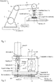
- FIG. 1 Figure 3 is an exemplary schematic illustration of a robotic grinding apparatus with a grinding machine coupled to an industrial robot by means of a force-controlled linear actuator;
- the linear actuator causes a mechanical decoupling of industrial robots and grinding machine.
- FIG. 2 illustrates an exemplary embodiment of a machine tool with integrated linear actuator for the mechanical decoupling of a drive side and a tool side of the machine tool.
- FIG. 3 illustrates another embodiment of a machine tool with mechanically decoupled drive side and tool side.
- FIG. 4 illustrates the example Fig. 3 however, with greater deflection the linear actuator than in Fig. 3
- the embodiments described herein are not limited to grinding devices.
- the devices described here can be used for the robot-aided execution of various machining processes in which a rotating tool is used (for example, all machining processes such as milling, grinding, polishing and the like.).
- FIG. 1 illustrated example includes a manipulator 1 (for example, an industrial robot) and a machine tool 3 (eg grinding machine), which has a motor 31 and a rotating tool 32 (eg grinding wheel).
- the grinding machine 3 is coupled to the End binorflansch 15 of the manipulator 1 (at the Tool Center Point (TCP)) via a linear actuator 2.
- the manipulator may be constructed of four segments 11, 12, 13 and 14, each connected by joints G 11 , G 12 and G 13 .
- the first segment 11 is usually rigidly connected to a foundation 10 (which, however, does not necessarily have to be the case).
- the hinge G 13 connects the segments 13 and 14.
- the hinge G 13 can be 2-axis and allow rotation of the segment 14 (relative to the segment 13) about a horizontal axis of rotation (elevation angle) and a vertical axis of rotation (azimuth angle).
- the joint G 12 connects the segments 12 and 13 and allows a pivoting movement of the segment 13 relative to the position of the segment 12.
- the joint G 11 connects the segments 11 and 12.
- the joint G 11 may be 2-axis and therefore (similar to the Joint G 13 ) allow a pivoting movement in two directions.
- the TCP has a fixed relative position to the segment 14, which usually also comprises a pivot (not shown) that allows a rotational movement about a longitudinal axis A of the segment 14 (in FIG Fig. 1 drawn as a dash-dotted line).
- the manipulator 1 thus has a total of 6 degrees of freedom.
- Each axis of a joint is associated with an actuator that can cause a rotational movement about the respective joint axis.
- the actuators in the joints are controlled by a robot controller 4 in accordance with a robot program.
- the TCP can be arbitrarily positioned (within certain limits) (with any orientation of axis A).
- the manipulator 1 is usually position-controlled, ie the robot controller 4 can set the pose (position and orientation) of the TCP and move it along a predefined trajectory.
- the pose of the TCP also defines the pose of the tool 32 (and the entire grinding machine 3).
- the actuator 2 serves to set the contact force F K (process force) between the tool 32 and the workpiece W to a desired value during the grinding process.
- F K process force
- a direct control of the process force by the manipulator 1 is usually too imprecise for grinding applications, as due to the high inertia of the segments 11 to 14 of the manipulator 1, a rapid compensation of force peaks (eg when placing the grinding tool on the workpiece W) is virtually impossible with conventional manipulators.
- the robot controller is adapted to control the pose (position and orientation) of the TCP, while the control of the contact force F K is accomplished solely by the actuator 2 coupled between the grinding machine 3 and the manipulator 1. Due to the force control of the actuator 2 is able to compensate for deviations in position and position of the workpiece W relative to the tool 32 during the grinding process (along the effective direction of the actuator 2) and at the same time maintain the desired process force F K.
- the mentioned deviations can be caused for example by errors in the positioning of the workpiece or inaccuracies in the positioning of the TCP (due to tolerances).
- the contact force F K between the tool 32 and the workpiece W can be adjusted by means of the (linear) actuator 2 and a force control unit (which may be implemented in the controller 4, for example) such that the contact force F K between Grinding tool 32 and workpiece W corresponds to a predetermined target value.
- the contact force is a reaction to the actuator force F A , with which the linear actuator 2 presses on the workpiece surface.
- the actuator 2 moves due to the lack of contact force F K against an end stop (in Fig. 1 not shown or integrated into the actuator 2).
- the position control of the manipulator 1 (which may also be implemented in the controller 4) can operate completely independently of the force control of the actuator 2.
- the actuator 2 is not responsible for the positioning of the grinding machine 3, but only for setting and maintaining the desired contact force F K during the grinding process and for detecting contact between tool 32 and workpiece W.
- a contact can be detected, for example, when the deflection of the actuator 2 starting from the end stop is smaller, or the change in the deflection of the actuator 2 is negative.
- the resulting shock-like contact force may be unproblematic in many cases, but may be troublesome and undesirable in applications where precision is important or very delicate workpieces must be processed. That is, there is an overshoot of the actual contact force compared to the target contact force. Even during the machining of a surface, it may be necessary to readjust the position of the tool in order to maintain the desired contact force. In this case, it is above all stiction effects (the so-called "stick-slip effect”) which can lead to transient overshoots in the force of contact force. Furthermore, in geared drives meshing of the teeth of the gears cause unwanted jerky shocks or vibrations. When handling or editing objects, both effects can cause quality issues.
- the overshoot explained above can be reduced by mechanically decoupling the machine tool (eg a grinding machine) from the manipulator 1.
- This decoupling can be achieved, for example, by means of a spring.
- this decoupling takes place by means of the actuator 2.
- the actuator 2 may be a pneumatic actuator, such as a double-acting pneumatic cylinder.
- other pneumatic actuators are applicable such as bellows cylinder and air muscle.
- electrical direct drives come into consideration.
- the force control can be realized in a conventional manner by means of a control valve, a controller (implemented in the controller 4) and a compressed air reservoir.
- the actuator 2 is substantially free of friction to avoid the mentioned stick-slip effect or to keep it as small as possible. "Essentially free of friction” does not mean a static friction of zero, but a negligible static friction compared to the actuator force. With complete decoupling between Machine tool and manipulator no longer affect the mass inertia forces of the manipulator on the contacted surface.
- the inertia forces of the machine tool still remain, which can act on the surface of the contacted workpiece.
- the machine tool typically requires a powerful motor (e.g., an electric motor) having a correspondingly large mass.
- the actuator 2 must be matched to the weight of the machine tool (including motor), since the actuator in the force control usually the weight of the machine tool (at least partially) must compensate.
- FIG. 2 shows an exemplary example of a machine tool 3 (eg a grinding machine) with integrated actuator 2.
- the integration of the actuator in the machine tool allows mechanical decoupling between a drive side on which the (comparatively heavy) motor 31 is arranged, and a tool side on which the (comparatively light) tool 32 (eg a grinding wheel) is arranged.
- the machine tool 3 has a first carrier plate 51 and a second carrier plate 52.
- the first support plate 51 is designed so that it can be mounted on a manipulator, for example on the End binorflansch 15 of the manipulator 1 from Fig. 1 .
- an output shaft 58 is mounted on the second support plate 52.
- a rotatable tool 32 may be mounted on the output shaft 58, for example a grinding wheel.
- a linear actuator 2 is arranged between the two support plates 51 and 52.
- the linear actuator 2 acts between the two support plates 51 and 52, so that the distance a between the two support plates 51 and 52 depends on the deflection of the linear actuator 2.
- the linear actuator 2 is operated under normal force control, so that the actuator force between the two support plates 51 and 52 acts. When the tool 32 is not in contact with a surface, the linear actuator 2 presses against a limit stop (not shown) with a desired actuator force.
- the actuator 2 may be a pneumatic linear actuator and include, for example, a double-acting pneumatic cylinder. However, other pneumatic actuators can be used such as bellows cylinder and air muscle. As an alternative, electrical direct drives (gearless) come into consideration.
- a motor 31 (e.g., an electric motor) for driving the tool 32 is mounted on the first support plate 51.
- the motor 31 may be flanged to the first support plate 51, the motor shaft 33 being passed through the first support plate 51.
- the distance between the two carrier plates 51 and 52 is "bridged" by a telescopic shaft 54.
- the telescopic shaft 54 comprises two shaft parts (hollow shaft / sleeve 541, drive shaft 543) which are displaceable relative to each other.
- a first part of the two shaft parts is coupled to the motor shaft 33 of the motor 31 (for example by means of a shaft coupling), and a second part of the two shaft parts is mounted on the second support plate 52, for example by means of a roller bearing.
- plain bearings can also be used.
- the aforementioned output shaft 58 is coupled to the telescopic shaft 54 via a gear, so that the motor shaft 33, the telescopic shaft 54 and the telescopic shaft (via the transmission), the output shaft 58 drives.
- the transmission is a belt drive.
- a belt eg a V-belt or a toothed belt
- the output shaft 58 and thus also the tool 32 mounted thereon eg a grinding wheel
- the drive shaft 543 (second shaft part) is displaceable relative to the hollow shaft 541 (first shaft part) along the axis of rotation of the telescopic shaft 54.
- the second shaft portion of the telescopic shaft 54 is passed through the second support plate 52, wherein the second shaft portion of the telescopic shaft 54 by means of a rolling bearing (eg, a ball bearing) can be mounted on the second support plate 52.
- the first shaft part of the telescopic shaft 54 may be fixedly connected to the motor shaft 33 of the motor 31 by means of a (eg rigid) shaft coupling 53. If, as in the present example, the motor 31 is flanged to the first support plate 51 so that the motor shaft 33 is passed through the support plate 51, the shaft coupling 53 is located between the two support plates 51 and 52nd
- the linear actuator 2 can act unimpeded on the second support plate 52, it may be useful that the linear movement between the two shaft parts of the telescopic shaft 54 along the axis of rotation of the telescopic shaft 54 has as little effect on the actuator. Therefore, the first shaft portion and the second shaft portion of the telescopic shaft 54 may be slidably supported by a linear bearing 542 to each other.
- the linear bearing 542 has a (negligible) low static friction, it may be formed as a linear ball bearing with axial ball circulation (ball bearing).
- the linear actuator 2 acts along a longitudinal axis A '.
- This axis A ' can be coaxial with a rotation axis A "of the output shaft 58.
- this longitudinal axis A' of the linear actuator 2 can also be aligned with the TCP of the manipulator 1 so that TCP and longitudinal axis A '(and also axis of rotation A") to be in flight.
- the linear actuator 2 - when mounted on the end effector flange of a manipulator - acts in a line between TCP of the manipulator and the axis of rotation A "of the output shaft 58 on which the tool 32 is mounted, reducing the bending moment load of the linear actuator and telescoping shaft.
- FIG. 3 illustrates another embodiment of a machine tool, in which the drive side (support plate 51, motor 31) and tool side (second support plate 52, output shaft 58, gear) by means of a linear actuator 2 and a telescopic shaft 54 are mechanically decoupled.
- This decoupling decouples the dynamics of the components on the drive side including the manipulator from the dynamics of the tool side.
- the embodiment of Fig. 3 is essentially the same as the previous one Example off Fig. 2 , wherein the belt drive has been omitted for clarity.
- the bearing 61 can be seen, on which the telescopic shaft 54 is mounted on the second support plate 52.
- the connection between telescopic shaft 54 and shaft coupling 53 is shown in more detail (see key P).
- the ball of the linear ball bearing are not shown, but you can see the grooves 544 in which the balls are guided.
- FIG. 4 shows the same embodiment as Fig. 3 However, wherein the deflection a 1 of the linear actuator 2 is greater than in Fig. 3 , Incidentally, the example is off Fig. 4 identical to the previous example Fig. 3 and the description thereof will therefore not be repeated.
- the exemplary embodiments described here were realized by means of a concrete selection from many possible components (machine elements). It should be noted at this point that many of the components used for the realization of the exemplary embodiments illustrated here can be replaced by other components which fulfill substantially the same or a similar function. For example, those in the embodiment according to Fig. 3 Instead of rolling bearings at one or more points and plain bearings are used, which may be useful, for example, at higher speeds. Furthermore, the belt drive can be replaced by any other type of transmission, for example by a gear transmission. Although a pneumatic linear actuator may be beneficial in many applications, in certain applications, another actuator (eg, an electrical actuator) may also be used.
- the wave connections do not necessarily have to be realized as in the illustrated embodiments according to Fig.
Landscapes
- Engineering & Computer Science (AREA)
- Mechanical Engineering (AREA)
- Robotics (AREA)
- Manipulator (AREA)
- Machine Tool Units (AREA)
- Finish Polishing, Edge Sharpening, And Grinding By Specific Grinding Devices (AREA)
Applications Claiming Priority (2)
| Application Number | Priority Date | Filing Date | Title |
|---|---|---|---|
| DE102016118173.0A DE102016118173A1 (de) | 2016-09-26 | 2016-09-26 | Werkzeugmaschine zum robotergestützten bearbeiten von oberflächen |
| PCT/EP2017/074327 WO2018055189A1 (de) | 2016-09-26 | 2017-09-26 | Werkzeugmaschine zum robotergestützten bearbeiten von oberflächen |
Publications (2)
| Publication Number | Publication Date |
|---|---|
| EP3325214A1 EP3325214A1 (de) | 2018-05-30 |
| EP3325214B1 true EP3325214B1 (de) | 2018-10-03 |
Family
ID=60083274
Family Applications (1)
| Application Number | Title | Priority Date | Filing Date |
|---|---|---|---|
| EP17783766.3A Active EP3325214B1 (de) | 2016-09-26 | 2017-09-26 | Werkzeugmaschine zum robotergestützten bearbeiten von oberflächen |
Country Status (7)
| Country | Link |
|---|---|
| US (1) | US11260537B2 (enExample) |
| EP (1) | EP3325214B1 (enExample) |
| JP (1) | JP7093342B2 (enExample) |
| KR (1) | KR102338659B1 (enExample) |
| CN (1) | CN109789528B (enExample) |
| DE (2) | DE102016118173A1 (enExample) |
| WO (1) | WO2018055189A1 (enExample) |
Cited By (2)
| Publication number | Priority date | Publication date | Assignee | Title |
|---|---|---|---|---|
| DE102020101384A1 (de) | 2019-01-23 | 2020-07-23 | Ferrobotics Compliant Robot Technology Gmbh | Robotergestützte schleifvorrichtung mit integrierter wartungseinheit |
| DE102019101579A1 (de) | 2019-01-23 | 2020-08-06 | Ferrobotics Compliant Robot Technology Gmbh | Robotergestützte schleifvorrichtung mit integrierter wartungseinheit |
Families Citing this family (12)
| Publication number | Priority date | Publication date | Assignee | Title |
|---|---|---|---|---|
| KR102838341B1 (ko) * | 2019-04-19 | 2025-07-23 | 페로보틱스 컴플라이언트 로봇 테크놀로지 게엠베하 | 표면들의 로봇-보조 기계가공을 위한 장치 |
| CN111015461A (zh) * | 2019-12-17 | 2020-04-17 | 安徽工程大学 | 一种打磨机器人柔性作业工具 |
| DE202019107127U1 (de) * | 2019-12-19 | 2021-03-22 | Ferrobotics Compliant Robot Technology Gmbh | Wellenkupplung für Werkzeugmaschinen |
| HRP20200144A2 (hr) | 2020-01-29 | 2021-08-06 | Amtos Solutions D.O.O. | Uređaj za aktivno upravljanje kontaktnom silom u postupcima obrade |
| US12194615B1 (en) * | 2020-02-10 | 2025-01-14 | The United States of America as represented by the Secretary of the U.S. Navy | Surface removal system |
| NL2024933B1 (en) * | 2020-02-18 | 2021-09-16 | Tollenaar Ind B V | Grinding or polishing device and method for treating of a workpiece |
| EP3932600B1 (en) * | 2020-06-30 | 2024-02-14 | 3M Innovative Properties Company | Process of grinding and polishing gear wheels |
| CN111872946A (zh) * | 2020-07-02 | 2020-11-03 | 深圳先进技术研究院 | 一种室内装修机器人 |
| EP4194144A4 (en) * | 2020-10-14 | 2024-01-10 | JFE Steel Corporation | DEFECT RECTIFICATION SYSTEM, DEFECT RECTIFICATION METHOD, AND METHOD FOR MANUFACTURING STEEL PRODUCT USING SAME |
| DE102020131967A1 (de) * | 2020-12-02 | 2022-06-02 | Ferrobotics Compliant Robot Technology Gmbh | Werkzeugmaschine für robotergestütztes bearbeiten von werkstücken mit zwei rotierbaren werkzeugen |
| CN114670050A (zh) * | 2022-03-22 | 2022-06-28 | 金川集团股份有限公司 | 一种自动取件装置 |
| CN114986322B (zh) * | 2022-08-01 | 2022-10-21 | 江苏欧远地板有限公司 | 一种木材打磨装置 |
Family Cites Families (22)
| Publication number | Priority date | Publication date | Assignee | Title |
|---|---|---|---|---|
| JPS5966177A (ja) * | 1982-10-07 | 1984-04-14 | Rohm Co Ltd | ホ−ル素子 |
| JPS60178556A (ja) | 1984-02-24 | 1985-09-12 | Fujitsu Ltd | 状態表示方式 |
| JPS60178556U (ja) * | 1984-05-07 | 1985-11-27 | トヨタ自動車株式会社 | ロボツト等における定力押付機構 |
| JPS61260973A (ja) * | 1985-05-13 | 1986-11-19 | Daikin Ind Ltd | ロボツト用ハンド |
| JPS62162322A (ja) * | 1986-01-13 | 1987-07-18 | アルプス電気株式会社 | ネツトワ−ク電子部品の製造方法 |
| JPH0166964U (enExample) * | 1987-10-23 | 1989-04-28 | ||
| FR2680946B1 (fr) * | 1991-09-05 | 1993-12-03 | Pellenc Motte Ets | Machine robotisee comportant un prehenseur, agissant par aspiration, par exemple pour le cueillage de fruits. |
| JPH0691581A (ja) * | 1992-09-10 | 1994-04-05 | Torai Eng Kk | 多軸ロボットに用いられるツールまたはワークの支持装置 |
| US5569060A (en) * | 1993-05-27 | 1996-10-29 | Hitachi, Ltd. | On-line roll grinding apparatus |
| JPH0732286A (ja) | 1993-07-20 | 1995-02-03 | Tokico Ltd | 工業用ロボット |
| JPH07136970A (ja) * | 1993-11-12 | 1995-05-30 | Toshiba Corp | ロボットハンド及びロボット |
| US6638139B2 (en) * | 2001-05-18 | 2003-10-28 | Acme Manufacturing Company | Multi-spindle end effector |
| US20030181145A1 (en) | 2002-03-21 | 2003-09-25 | Collins Mark E. | Automotive safety glass edge polishing |
| US20040259471A1 (en) * | 2003-06-23 | 2004-12-23 | Antenen Research Co. | Articulating constant force finishing tool actuator |
| WO2006054693A1 (ja) * | 2004-11-22 | 2006-05-26 | Matsushita Electric Industrial Co., Ltd. | 関節構造体及びロボットアーム |
| KR200422315Y1 (ko) | 2006-04-28 | 2006-07-25 | 주식회사 싸이맥스 | 이중 아암 로봇 |
| DE102011006679B4 (de) * | 2011-03-16 | 2018-07-12 | Ferrobotics Compliant Robot Technology Gmbh | Aktive Handhabungsvorrichtung und Verfahren für Kontaktaufgaben |
| WO2013059705A1 (en) * | 2011-10-21 | 2013-04-25 | Strasbaugh | Systems and methods of wafer grinding |
| US9573237B2 (en) * | 2012-08-31 | 2017-02-21 | Matuschek Messtechnik Gmbh | Device and method for grinding workpieces, in particular welding electrodes |
| DE102014119532B4 (de) | 2014-12-23 | 2016-11-03 | Ferrobotics Compliant Robot Technology Gmbh | Robotergestütztes Schleifverfahren und Vorrichtung zum robotergestützten Schleifen |
| DE102015104164B4 (de) * | 2015-03-19 | 2019-05-29 | Ferrobotics Compliant Robot Technology Gmbh | Verfahren und Vorrichtung zur robotergestützten Oberflächenbearbeitung |
| CN105196296A (zh) | 2015-08-13 | 2015-12-30 | 江苏汇博机器人技术有限公司 | 一种应用于打磨工业机器人作业的末端力反馈系统及方法 |
-
2016
- 2016-09-26 DE DE102016118173.0A patent/DE102016118173A1/de not_active Withdrawn
-
2017
- 2017-09-26 KR KR1020197007711A patent/KR102338659B1/ko active Active
- 2017-09-26 CN CN201780059434.0A patent/CN109789528B/zh active Active
- 2017-09-26 DE DE112017003503.1T patent/DE112017003503A5/de active Pending
- 2017-09-26 EP EP17783766.3A patent/EP3325214B1/de active Active
- 2017-09-26 WO PCT/EP2017/074327 patent/WO2018055189A1/de not_active Ceased
- 2017-09-26 US US16/336,410 patent/US11260537B2/en active Active
- 2017-09-26 JP JP2019516469A patent/JP7093342B2/ja active Active
Non-Patent Citations (1)
| Title |
|---|
| None * |
Cited By (2)
| Publication number | Priority date | Publication date | Assignee | Title |
|---|---|---|---|---|
| DE102020101384A1 (de) | 2019-01-23 | 2020-07-23 | Ferrobotics Compliant Robot Technology Gmbh | Robotergestützte schleifvorrichtung mit integrierter wartungseinheit |
| DE102019101579A1 (de) | 2019-01-23 | 2020-08-06 | Ferrobotics Compliant Robot Technology Gmbh | Robotergestützte schleifvorrichtung mit integrierter wartungseinheit |
Also Published As
| Publication number | Publication date |
|---|---|
| KR102338659B1 (ko) | 2021-12-13 |
| JP2019534165A (ja) | 2019-11-28 |
| KR20190060992A (ko) | 2019-06-04 |
| WO2018055189A1 (de) | 2018-03-29 |
| EP3325214A1 (de) | 2018-05-30 |
| US11260537B2 (en) | 2022-03-01 |
| DE102016118173A1 (de) | 2018-03-29 |
| CN109789528B (zh) | 2021-06-04 |
| CN109789528A (zh) | 2019-05-21 |
| DE112017003503A5 (de) | 2019-05-09 |
| US20190232502A1 (en) | 2019-08-01 |
| JP7093342B2 (ja) | 2022-06-29 |
Similar Documents
| Publication | Publication Date | Title |
|---|---|---|
| EP3325214B1 (de) | Werkzeugmaschine zum robotergestützten bearbeiten von oberflächen | |
| EP2686142B1 (de) | Aktive handhabungsvorrichtung und verfahren für kontaktaufgaben | |
| EP3439836B1 (de) | Robotergestützte schleifvorrichtung | |
| EP3956102B1 (de) | Vorrichtung zum bearbeiten von oberflächen | |
| EP3481605B1 (de) | Verfahren und system zum automatischen wechseln von wellen | |
| EP3765239B1 (de) | Drehzahlsteuerung beim robotergestützten schleifen | |
| DE102015104164B4 (de) | Verfahren und Vorrichtung zur robotergestützten Oberflächenbearbeitung | |
| EP3612350B1 (de) | Schleifmaschine zum robotergestützten schleifen | |
| EP3288712B1 (de) | Vorrichtung zur oberflächenbearbeitung | |
| DE102015119589A1 (de) | Vorrichtung und Verfahren zum robotergestützen Rollfalzen | |
| DE102015111636A1 (de) | Computergesteuerte Bewegungseinrichtung zur Verbesserung des Ergebnisses eines subtraktiven Bearbeitungsvorgangs | |
| EP3697567B1 (de) | Absaugung für schleifwerkzeug mit radialbürstenscheibe | |
| DE102022110487B4 (de) | Pneumatischer linearaktor | |
| EP3934862B1 (de) | Schnellspannsystem zur verbindung von werkzeugmaschinen mit einem roboter | |
| DE202005007792U1 (de) | Halterung für einen Werkzeugantrieb, insbesondere zum automatischen Entgraten, Kantenbrechen oder Verputzen von Werkstücken |
Legal Events
| Date | Code | Title | Description |
|---|---|---|---|
| STAA | Information on the status of an ep patent application or granted ep patent |
Free format text: STATUS: UNKNOWN |
|
| STAA | Information on the status of an ep patent application or granted ep patent |
Free format text: STATUS: THE INTERNATIONAL PUBLICATION HAS BEEN MADE |
|
| PUAI | Public reference made under article 153(3) epc to a published international application that has entered the european phase |
Free format text: ORIGINAL CODE: 0009012 |
|
| STAA | Information on the status of an ep patent application or granted ep patent |
Free format text: STATUS: REQUEST FOR EXAMINATION WAS MADE |
|
| 17P | Request for examination filed |
Effective date: 20180223 |
|
| AK | Designated contracting states |
Kind code of ref document: A1 Designated state(s): AL AT BE BG CH CY CZ DE DK EE ES FI FR GB GR HR HU IE IS IT LI LT LU LV MC MK MT NL NO PL PT RO RS SE SI SK SM TR |
|
| AX | Request for extension of the european patent |
Extension state: BA ME |
|
| GRAP | Despatch of communication of intention to grant a patent |
Free format text: ORIGINAL CODE: EPIDOSNIGR1 |
|
| STAA | Information on the status of an ep patent application or granted ep patent |
Free format text: STATUS: GRANT OF PATENT IS INTENDED |
|
| GRAS | Grant fee paid |
Free format text: ORIGINAL CODE: EPIDOSNIGR3 |
|
| GRAJ | Information related to disapproval of communication of intention to grant by the applicant or resumption of examination proceedings by the epo deleted |
Free format text: ORIGINAL CODE: EPIDOSDIGR1 |
|
| GRAL | Information related to payment of fee for publishing/printing deleted |
Free format text: ORIGINAL CODE: EPIDOSDIGR3 |
|
| STAA | Information on the status of an ep patent application or granted ep patent |
Free format text: STATUS: REQUEST FOR EXAMINATION WAS MADE |
|
| DAV | Request for validation of the european patent (deleted) | ||
| DAX | Request for extension of the european patent (deleted) | ||
| INTG | Intention to grant announced |
Effective date: 20180716 |
|
| GRAR | Information related to intention to grant a patent recorded |
Free format text: ORIGINAL CODE: EPIDOSNIGR71 |
|
| STAA | Information on the status of an ep patent application or granted ep patent |
Free format text: STATUS: GRANT OF PATENT IS INTENDED |
|
| GRAA | (expected) grant |
Free format text: ORIGINAL CODE: 0009210 |
|
| STAA | Information on the status of an ep patent application or granted ep patent |
Free format text: STATUS: THE PATENT HAS BEEN GRANTED |
|
| INTC | Intention to grant announced (deleted) | ||
| AK | Designated contracting states |
Kind code of ref document: B1 Designated state(s): AL AT BE BG CH CY CZ DE DK EE ES FI FR GB GR HR HU IE IS IT LI LT LU LV MC MK MT NL NO PL PT RO RS SE SI SK SM TR |
|
| INTG | Intention to grant announced |
Effective date: 20180828 |
|
| REG | Reference to a national code |
Ref country code: GB Ref legal event code: FG4D Free format text: NOT ENGLISH |
|
| REG | Reference to a national code |
Ref country code: CH Ref legal event code: EP Ref country code: AT Ref legal event code: REF Ref document number: 1048102 Country of ref document: AT Kind code of ref document: T Effective date: 20181015 |
|
| REG | Reference to a national code |
Ref country code: DE Ref legal event code: R096 Ref document number: 502017000237 Country of ref document: DE Ref country code: IE Ref legal event code: FG4D Free format text: LANGUAGE OF EP DOCUMENT: GERMAN |
|
| REG | Reference to a national code |
Ref country code: NL Ref legal event code: MP Effective date: 20181003 |
|
| REG | Reference to a national code |
Ref country code: LT Ref legal event code: MG4D |
|
| PG25 | Lapsed in a contracting state [announced via postgrant information from national office to epo] |
Ref country code: NL Free format text: LAPSE BECAUSE OF FAILURE TO SUBMIT A TRANSLATION OF THE DESCRIPTION OR TO PAY THE FEE WITHIN THE PRESCRIBED TIME-LIMIT Effective date: 20181003 |
|
| PG25 | Lapsed in a contracting state [announced via postgrant information from national office to epo] |
Ref country code: LV Free format text: LAPSE BECAUSE OF FAILURE TO SUBMIT A TRANSLATION OF THE DESCRIPTION OR TO PAY THE FEE WITHIN THE PRESCRIBED TIME-LIMIT Effective date: 20181003 Ref country code: ES Free format text: LAPSE BECAUSE OF FAILURE TO SUBMIT A TRANSLATION OF THE DESCRIPTION OR TO PAY THE FEE WITHIN THE PRESCRIBED TIME-LIMIT Effective date: 20181003 Ref country code: NO Free format text: LAPSE BECAUSE OF FAILURE TO SUBMIT A TRANSLATION OF THE DESCRIPTION OR TO PAY THE FEE WITHIN THE PRESCRIBED TIME-LIMIT Effective date: 20190103 Ref country code: FI Free format text: LAPSE BECAUSE OF FAILURE TO SUBMIT A TRANSLATION OF THE DESCRIPTION OR TO PAY THE FEE WITHIN THE PRESCRIBED TIME-LIMIT Effective date: 20181003 Ref country code: IS Free format text: LAPSE BECAUSE OF FAILURE TO SUBMIT A TRANSLATION OF THE DESCRIPTION OR TO PAY THE FEE WITHIN THE PRESCRIBED TIME-LIMIT Effective date: 20190203 Ref country code: CZ Free format text: LAPSE BECAUSE OF FAILURE TO SUBMIT A TRANSLATION OF THE DESCRIPTION OR TO PAY THE FEE WITHIN THE PRESCRIBED TIME-LIMIT Effective date: 20181003 Ref country code: BG Free format text: LAPSE BECAUSE OF FAILURE TO SUBMIT A TRANSLATION OF THE DESCRIPTION OR TO PAY THE FEE WITHIN THE PRESCRIBED TIME-LIMIT Effective date: 20190103 Ref country code: LT Free format text: LAPSE BECAUSE OF FAILURE TO SUBMIT A TRANSLATION OF THE DESCRIPTION OR TO PAY THE FEE WITHIN THE PRESCRIBED TIME-LIMIT Effective date: 20181003 Ref country code: PL Free format text: LAPSE BECAUSE OF FAILURE TO SUBMIT A TRANSLATION OF THE DESCRIPTION OR TO PAY THE FEE WITHIN THE PRESCRIBED TIME-LIMIT Effective date: 20181003 Ref country code: HR Free format text: LAPSE BECAUSE OF FAILURE TO SUBMIT A TRANSLATION OF THE DESCRIPTION OR TO PAY THE FEE WITHIN THE PRESCRIBED TIME-LIMIT Effective date: 20181003 |
|
| PG25 | Lapsed in a contracting state [announced via postgrant information from national office to epo] |
Ref country code: RS Free format text: LAPSE BECAUSE OF FAILURE TO SUBMIT A TRANSLATION OF THE DESCRIPTION OR TO PAY THE FEE WITHIN THE PRESCRIBED TIME-LIMIT Effective date: 20181003 Ref country code: GR Free format text: LAPSE BECAUSE OF FAILURE TO SUBMIT A TRANSLATION OF THE DESCRIPTION OR TO PAY THE FEE WITHIN THE PRESCRIBED TIME-LIMIT Effective date: 20190104 Ref country code: SE Free format text: LAPSE BECAUSE OF FAILURE TO SUBMIT A TRANSLATION OF THE DESCRIPTION OR TO PAY THE FEE WITHIN THE PRESCRIBED TIME-LIMIT Effective date: 20181003 Ref country code: PT Free format text: LAPSE BECAUSE OF FAILURE TO SUBMIT A TRANSLATION OF THE DESCRIPTION OR TO PAY THE FEE WITHIN THE PRESCRIBED TIME-LIMIT Effective date: 20190203 Ref country code: AL Free format text: LAPSE BECAUSE OF FAILURE TO SUBMIT A TRANSLATION OF THE DESCRIPTION OR TO PAY THE FEE WITHIN THE PRESCRIBED TIME-LIMIT Effective date: 20181003 |
|
| REG | Reference to a national code |
Ref country code: DE Ref legal event code: R097 Ref document number: 502017000237 Country of ref document: DE |
|
| PG25 | Lapsed in a contracting state [announced via postgrant information from national office to epo] |
Ref country code: DK Free format text: LAPSE BECAUSE OF FAILURE TO SUBMIT A TRANSLATION OF THE DESCRIPTION OR TO PAY THE FEE WITHIN THE PRESCRIBED TIME-LIMIT Effective date: 20181003 |
|
| PLBE | No opposition filed within time limit |
Free format text: ORIGINAL CODE: 0009261 |
|
| STAA | Information on the status of an ep patent application or granted ep patent |
Free format text: STATUS: NO OPPOSITION FILED WITHIN TIME LIMIT |
|
| PG25 | Lapsed in a contracting state [announced via postgrant information from national office to epo] |
Ref country code: SK Free format text: LAPSE BECAUSE OF FAILURE TO SUBMIT A TRANSLATION OF THE DESCRIPTION OR TO PAY THE FEE WITHIN THE PRESCRIBED TIME-LIMIT Effective date: 20181003 Ref country code: SM Free format text: LAPSE BECAUSE OF FAILURE TO SUBMIT A TRANSLATION OF THE DESCRIPTION OR TO PAY THE FEE WITHIN THE PRESCRIBED TIME-LIMIT Effective date: 20181003 Ref country code: RO Free format text: LAPSE BECAUSE OF FAILURE TO SUBMIT A TRANSLATION OF THE DESCRIPTION OR TO PAY THE FEE WITHIN THE PRESCRIBED TIME-LIMIT Effective date: 20181003 Ref country code: EE Free format text: LAPSE BECAUSE OF FAILURE TO SUBMIT A TRANSLATION OF THE DESCRIPTION OR TO PAY THE FEE WITHIN THE PRESCRIBED TIME-LIMIT Effective date: 20181003 |
|
| 26N | No opposition filed |
Effective date: 20190704 |
|
| PG25 | Lapsed in a contracting state [announced via postgrant information from national office to epo] |
Ref country code: TR Free format text: LAPSE BECAUSE OF FAILURE TO SUBMIT A TRANSLATION OF THE DESCRIPTION OR TO PAY THE FEE WITHIN THE PRESCRIBED TIME-LIMIT Effective date: 20181003 |
|
| PG25 | Lapsed in a contracting state [announced via postgrant information from national office to epo] |
Ref country code: MC Free format text: LAPSE BECAUSE OF FAILURE TO SUBMIT A TRANSLATION OF THE DESCRIPTION OR TO PAY THE FEE WITHIN THE PRESCRIBED TIME-LIMIT Effective date: 20181003 |
|
| PG25 | Lapsed in a contracting state [announced via postgrant information from national office to epo] |
Ref country code: IE Free format text: LAPSE BECAUSE OF NON-PAYMENT OF DUE FEES Effective date: 20190926 Ref country code: LU Free format text: LAPSE BECAUSE OF NON-PAYMENT OF DUE FEES Effective date: 20190926 |
|
| REG | Reference to a national code |
Ref country code: BE Ref legal event code: MM Effective date: 20190930 |
|
| PG25 | Lapsed in a contracting state [announced via postgrant information from national office to epo] |
Ref country code: BE Free format text: LAPSE BECAUSE OF NON-PAYMENT OF DUE FEES Effective date: 20190930 |
|
| PG25 | Lapsed in a contracting state [announced via postgrant information from national office to epo] |
Ref country code: IT Free format text: LAPSE BECAUSE OF FAILURE TO SUBMIT A TRANSLATION OF THE DESCRIPTION OR TO PAY THE FEE WITHIN THE PRESCRIBED TIME-LIMIT Effective date: 20181003 |
|
| REG | Reference to a national code |
Ref country code: CH Ref legal event code: PL |
|
| PG25 | Lapsed in a contracting state [announced via postgrant information from national office to epo] |
Ref country code: CY Free format text: LAPSE BECAUSE OF FAILURE TO SUBMIT A TRANSLATION OF THE DESCRIPTION OR TO PAY THE FEE WITHIN THE PRESCRIBED TIME-LIMIT Effective date: 20181003 |
|
| PG25 | Lapsed in a contracting state [announced via postgrant information from national office to epo] |
Ref country code: HU Free format text: LAPSE BECAUSE OF FAILURE TO SUBMIT A TRANSLATION OF THE DESCRIPTION OR TO PAY THE FEE WITHIN THE PRESCRIBED TIME-LIMIT; INVALID AB INITIO Effective date: 20170926 Ref country code: MT Free format text: LAPSE BECAUSE OF FAILURE TO SUBMIT A TRANSLATION OF THE DESCRIPTION OR TO PAY THE FEE WITHIN THE PRESCRIBED TIME-LIMIT Effective date: 20181003 |
|
| PG25 | Lapsed in a contracting state [announced via postgrant information from national office to epo] |
Ref country code: LI Free format text: LAPSE BECAUSE OF NON-PAYMENT OF DUE FEES Effective date: 20200930 Ref country code: CH Free format text: LAPSE BECAUSE OF NON-PAYMENT OF DUE FEES Effective date: 20200930 |
|
| PG25 | Lapsed in a contracting state [announced via postgrant information from national office to epo] |
Ref country code: SI Free format text: LAPSE BECAUSE OF FAILURE TO SUBMIT A TRANSLATION OF THE DESCRIPTION OR TO PAY THE FEE WITHIN THE PRESCRIBED TIME-LIMIT Effective date: 20181003 |
|
| PG25 | Lapsed in a contracting state [announced via postgrant information from national office to epo] |
Ref country code: MK Free format text: LAPSE BECAUSE OF FAILURE TO SUBMIT A TRANSLATION OF THE DESCRIPTION OR TO PAY THE FEE WITHIN THE PRESCRIBED TIME-LIMIT Effective date: 20181003 |
|
| REG | Reference to a national code |
Ref country code: AT Ref legal event code: MM01 Ref document number: 1048102 Country of ref document: AT Kind code of ref document: T Effective date: 20220926 |
|
| PG25 | Lapsed in a contracting state [announced via postgrant information from national office to epo] |
Ref country code: AT Free format text: LAPSE BECAUSE OF NON-PAYMENT OF DUE FEES Effective date: 20220926 |
|
| PGFP | Annual fee paid to national office [announced via postgrant information from national office to epo] |
Ref country code: GB Payment date: 20250923 Year of fee payment: 9 |
|
| PGFP | Annual fee paid to national office [announced via postgrant information from national office to epo] |
Ref country code: FR Payment date: 20250926 Year of fee payment: 9 |
|
| PGFP | Annual fee paid to national office [announced via postgrant information from national office to epo] |
Ref country code: DE Payment date: 20251028 Year of fee payment: 9 |