EP3323954A1 - Pfosten-riegel-konstruktion - Google Patents
Pfosten-riegel-konstruktion Download PDFInfo
- Publication number
- EP3323954A1 EP3323954A1 EP17200101.8A EP17200101A EP3323954A1 EP 3323954 A1 EP3323954 A1 EP 3323954A1 EP 17200101 A EP17200101 A EP 17200101A EP 3323954 A1 EP3323954 A1 EP 3323954A1
- Authority
- EP
- European Patent Office
- Prior art keywords
- post
- bolt
- construction according
- filling element
- mullion
- Prior art date
- Legal status (The legal status is an assumption and is not a legal conclusion. Google has not performed a legal analysis and makes no representation as to the accuracy of the status listed.)
- Granted
Links
Images




Classifications
-
- E—FIXED CONSTRUCTIONS
- E04—BUILDING
- E04B—GENERAL BUILDING CONSTRUCTIONS; WALLS, e.g. PARTITIONS; ROOFS; FLOORS; CEILINGS; INSULATION OR OTHER PROTECTION OF BUILDINGS
- E04B2/00—Walls, e.g. partitions, for buildings; Wall construction with regard to insulation; Connections specially adapted to walls
- E04B2/88—Curtain walls
- E04B2/96—Curtain walls comprising panels attached to the structure through mullions or transoms
- E04B2/962—Curtain walls comprising panels attached to the structure through mullions or transoms with angles or corners in the curtain wall
-
- E—FIXED CONSTRUCTIONS
- E06—DOORS, WINDOWS, SHUTTERS, OR ROLLER BLINDS IN GENERAL; LADDERS
- E06B—FIXED OR MOVABLE CLOSURES FOR OPENINGS IN BUILDINGS, VEHICLES, FENCES OR LIKE ENCLOSURES IN GENERAL, e.g. DOORS, WINDOWS, BLINDS, GATES
- E06B3/00—Window sashes, door leaves, or like elements for closing wall or like openings; Layout of fixed or moving closures, e.g. windows in wall or like openings; Features of rigidly-mounted outer frames relating to the mounting of wing frames
- E06B3/54—Fixing of glass panes or like plates
- E06B3/5409—Means for locally spacing the pane from the surrounding frame
Definitions
- the present invention relates to a mullion and transom construction, in particular for a facade, with a post on which at least two vertically spaced bars are provided, which protrude from the post, wherein between the bars a plate-shaped filling element is arranged, which on the bottom latch adjacent to the post is supported on a support.
- the DE 20 2013 105 586 U1 shows a facade construction in which plate-shaped filling elements are fixed to posts and transoms, which are edged between seals at the edge. On the outside An horrolinn are provided which are fixed by fasteners on the posts and bars. In addition, glass supports are provided in the crossing region between posts and bars in order to at least partially accommodate the weight loads of the insulating glass panes. In such facade constructions, there is the problem that in a corner area always a post is provided, so that the field of view is divided.
- a plate-shaped filling element is arranged between an upper and a lower latch and next to a post, wherein the filling element is supported on the lower latch adjacent to the post on a support.
- the removal of force can be done on the support via the bolt and / or the post, it could therefore be introduced directly into the post via the support, the force.
- Adjacent to the upper latch on the support area diagonally opposite corner region the filling element is held by a holding element.
- This allows the use of very filigree components on the opposite side to the post, since there essentially only one seal must be provided, but no higher weight loads must be recorded. In particular, it is thus also possible to produce a so-called all-glass corner.
- the holding element is arranged so that it supports the filling element on a vertical edge.
- the holding element engage around the filling element U-shaped or engage with a sword in a groove on the filling element.
- the holding element can be clamped or otherwise fixed to the filling element.
- the two bars are connected on the side facing away from the post with other bars, which are aligned at an angle to the bars.
- the bars can be connected to the other bars at an angle between 30 ° to 150 °, in particular 60 ° to 120 °, preferably at right angles.
- this corner in which the bars are arranged at an angle to each other, can be dispensed with the use of a post, since the weight forces are carried by the filling element on the support member and the lower support.
- the retaining element may be formed, for example, as an angle which is fixed to a bolt. As a result, the forces can be removed via the retaining element on the bolt.
- the holding element may be fixed on one side to the filling element and on the opposite side to the post.
- the retaining element preferably comprises a tension element, which may be formed as a rope, band, tie rod, profile, bolt or rod to accommodate appropriate tensile forces can.
- the filling element is preferably formed as insulating glass, which is held sealed at both bars and the post.
- the insulating glass pane can be connected to a further insulating glass pane.
- the further insulating glass pane can preferably be aligned at an angle to the insulating glass pane, in particular at right angles.
- the two insulating glass panes can be sealed to each other at the edge by sealing means.
- a mullion and transom construction 1 comprises vertical posts 2 to which a plurality of horizontal bars 3 are fixed.
- the bars 3 may be provided in the region of a lower floor ceiling 4 and an upper floor ceiling 5, wherein in addition optionally also bars 3 are arranged in a parapet area.
- the facade construction comprises a corner area in which no post 2 is provided. There are only two posts 2 spaced from the corner area provided, wherein in the corner region in each case a bolt 3 is connected to a further arranged at an angle latch 6.
- the bolt 3 and the further latch 6 may be aligned at right angles and connected to each other in the miter area via a corner connector.
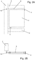
- FIGS. 2A and 2B is the structure of the mullion and transom construction of FIG. 1 shown with a filling element 7, in particular an insulating glass pane.
- the filling element 7 is surrounded by the two bars 3 and the post 2 and can be fixed there by clamping strips.
- a schematically illustrated support 17 is provided which is provided adjacent to the post 2 on the bolt 3 and, for example, may be formed as in the DE 20 2013 105 586 U1 in the FIGS. 10 to 13 is shown.
- no support is provided on the lower latch 3, since the latch 3 is not supported on a post 2 in this area.
- a holding element 8 which supports the filling element 7 in the upper corner area, which is opposite to the support 17 opposite.
- the holding element 8 is provided with a holder 9 which rests against a vertical edge of the filling element 7, for example the filling element 7 surrounds or is otherwise fixed in a U-shape, and is fastened to the post 2 via fastening means 10.
- the holding element 8 may comprise a cable, tie rod, tape, profile or a rod to accommodate the weight loads of the filling element 7, which would otherwise cause a pivoting of the filling element 7 to the support 17.
- FIG. 2 further shows the possibility of inserting the tension element as a rope directly into the marginal space between two glass panes or in a gluing of the space between the panes. This makes the construction more filigree - even in a horizontal orientation - which is especially desired in the corner area and in all-glass facades.
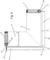
- FIG. 3 a corner region of the bolt 3 is shown in a plan view.
- the bolt 3 is fixed to a post 2, which has two grooves 20 for receiving sealing strips on an outer side, and a central groove 21, are provided on the fastening means 22 for fixing an outer pressure strip.
- the bars 3 have corresponding outer grooves for sealing strips, and the posts 2 and 3 bars can as in the DE 20 2013 105 586 U1 be educated.
- no post 2 is provided, so that the field of view of the observer in the room is only slightly limited.
- In the corner area meets an insulating glass pane as a filling element 7 on a further insulating glass pane as a filling element 7 ', which is aligned at right angles to the filling element 7.
- the filling element 7 is plate-shaped and comprises straight end edges.
- the further filling element 7 ' is also plate-shaped and comprises an outer glass plate 70 which protrudes on the outer side edge, so that the edge is formed angular. Through this angular configuration, a gap 72 is provided between the protruding glass pane 70 and an end face of the filling element 7, and a gap 73 on the inside of the filling element 7 and the end face of the further filling element 7 '.
- a seal via sealant, silicone or other components can be carried out, wherein the width of the column 72 and 73, for example, in a range between 4 mm to 30 mm, in particular 8 mm to 15 mm , As a result, the impairment of the field of view through the small gaps 72 and 73 is minimized.
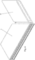
- FIG. 4 a corner region of the bolt 3 is shown, which is mitred on the side facing away from the post 2 side.
- the bolt 3 is formed as a hollow profile, as in FIG. 3 is shown, and in a hollow chamber of the bolt 3, a corner connector 30 is inserted.
- the corner connector 30 comprises a portion protruding from the latch 3, which is inserted into a further latch 6, which has the same cross-sectional geometry as the latch 3 and is arranged at an angle thereto, as shown in FIG FIG. 5 is shown.
- the bolt 3 and the further latch 6 are thus fixed to one another via the corner connector 30.
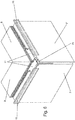
- FIG. 5 an embodiment of a retaining element 11 is shown, which is made as an angle.
- the holding element 11 comprises a first leg 12, which is fixed to the end of the bolt 3, for example, screwed into a central groove on the bolt 3 or fixed by clamping.
- the holding element 11 comprises an angle of the first leg 12 protruding second leg 13 which engages around a vertical end edge in the upper corner region of the filling element 7.
- the filling element 7 can thus be supported on the vertical leg 13, in particular via the interposition of spacers made of a plastic or softer material, to avoid damage to the insulating glass panes.
- a corresponding angle-shaped retaining element is also provided on the further latch 6, which surrounds a filling element 7 with a leg 12 on the further latch 6 and a vertical leg 13.
- a first filling element 7 and a further filling element 7 ' are mounted on the corner region.
- the holding element 11 engages around a vertical end edge of the filling element 7, while a second holding element 11 engages over a vertical holding edge of the further filling element 7 '.
- the further filling element 7 ' is designed as a stepped glass and has an outer glass pane 70 which protrudes at the edge ( FIG. 3 ) and thus also covers the vertical legs 13 of the two holding element 11.
- outer pressure bars 15 are provided which fix the filling elements 7 and 7' by means of sealing elements on the latch 3 and the further latch 6.
- the pressure strips 15 may extend into the corner region and be fixed by fastening means, in particular on protruding bolts of the holding elements 11.
- the filling elements 7, 7 'in the vertical and / or horizontal edge region with appropriate sealing and adhesives are attached to each other, so that z. B. a structural glazing or all-glass facade is created.
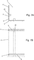
- FIGS. 7A and 7B a first arrangement of a corner region of the mullion and transom construction is shown, which is provided on a lower floor ceiling 4 and an upper floor ceiling 5.
- the floor slabs 4 and 5 are supported on building posts 25, wherein the floor slabs 4 and 5 extend into the corner region of the facade structure, so that no vertical passage is provided in the area of the floor slabs 4 and 5.
- the bolt 3 can thereby also be fixed to the floor slabs 4 and 5. Only bars 3 are provided in the area of the floor slabs 4 and 5, so that the filling elements are designed to be projectile high.
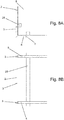
- FIG. 8A and 8B is the mullion and transom construction similar to FIG. 7 formed, however, in addition to a parapet area, for example, in a height between 80 cm and 1.20 m, a bolt 3 is provided which forms a parapet and optionally can also absorb tensile loads or weight loads of a filling element.
- FIG. 9A and 9B a facade construction is shown in which the floor slabs 4 and 5 have a recess 26 in a corner area, so that a vertical passage is formed between the individual floors. Otherwise the construction corresponds to the FIG. 7 ,
- FIG. 10 a further embodiment is shown in which instead of the two building posts 25 for supporting the floor slabs 4 and 5 a circular cross-section building post 28 is provided in the corner.
- the floor slab 5 is provided in the corner with a recess 27 which forms a rounded corner of the floor slab, while the facade construction with the bars 3 and the other bars 6 extends at right angles.
- FIGS. 7 to 10 show only exemplary installation situations that can be arbitrarily combined or varied with each other.
Landscapes
- Engineering & Computer Science (AREA)
- Civil Engineering (AREA)
- Structural Engineering (AREA)
- Architecture (AREA)
- Physics & Mathematics (AREA)
- Electromagnetism (AREA)
- Load-Bearing And Curtain Walls (AREA)
Abstract
Description
- Die vorliegende Erfindung betrifft eine Pfosten-Riegel-Konstruktion, insbesondere für eine Fassade, mit einem Pfosten, an dem mindestens zwei vertikal voneinander beabstandete Riegel vorgesehen sind, die von dem Pfosten hervorstehen, wobei zwischen den Riegeln ein plattenförmiges Füllungselement angeordnet ist, das an dem unteren Riegel benachbart zu dem Pfosten an einem Auflager abgestützt ist.
- Die
DE 20 2013 105 586 U1 zeigt eine Fassadenkonstruktion, bei der an Pfosten und Riegeln plattenförmige Füllungselemente fixiert sind, die randseitig zwischen Dichtungen eingefasst sind. An der Außenseite sind Andruckleisten vorgesehen, die über Befestigungsmittel an den Pfosten und Riegeln fixiert sind. Zudem sind im Kreuzungsbereich zwischen Pfosten und Riegeln Glasträger vorgesehen, um die Gewichtslasten der Isolierglasscheiben zumindest teilweise aufnehmen zu können. Bei solchen Fassadenkonstruktionen besteht das Problem, dass in einem Eckbereich immer ein Pfosten vorgesehen ist, so dass das Sichtfeld unterteilt ist. - Es ist daher Aufgabe der vorliegenden Erfindung, eine Pfosten-Riegel-Konstruktion bereitzustellen, die eine alternative Abstützung eines Füllungselementes ermöglicht, so dass insbesondere ein Eckbereich einer Pfosten-Riegel-Konstruktion optisch ansprechend gestaltet werden kann.
- Diese Aufgabe wird mit einer Pfosten-Riegel-Konstruktion mit den Merkmalen des Anspruches 1 gelöst.
- Erfindungsgemäß ist ein plattenförmiges Füllungselement zwischen einem oberen und einem unteren Riegel und neben einen Pfosten angeordnet, wobei das Füllungselement an dem unteren Riegel benachbart zu dem Pfosten an einem Auflager abgestützt ist. Die Kraftabtragung kann an dem Auflager über den Riegel und/oder den Pfosten erfolgen, es könnte daher auch die Kraft direkt in den Pfosten über das Auflager eingeleitet werden. Benachbart zu dem oberen Riegel an dem zum Auflager diagonal gegenüberliegenden Eckbereich ist das Füllungselement durch ein Halteelement gehalten. Dadurch kann auf ein weiteres Auflager am unteren Riegel verzichtet werden, so dass die Gewichtslasten des Füllungselementes im Wesentlichen durch das Auflager benachbart zu dem Pfosten und das Halteelement in dem diagonal gegenüberliegenden Eckbereich aufgenommen werden können. Dies ermöglicht den Einsatz sehr filigraner Bauteile auf der zum Pfosten gegenüberliegenden Seite, da dort im Wesentlichen nur eine Abdichtung bereitgestellt werden muss, aber keine höheren Gewichtslasten aufgenommen werden müssen. Insbesondere lässt sich damit auch eine sogenannte Ganzglasecke herstellen.
- Vorzugsweise ist das Halteelement so angeordnet, dass es an einer vertikalen Kante das Füllungselement abstützt. Dabei kann das Halteelement das Füllungselement U-förmig umgreifen oder mit einem Schwert in eine Nut an dem Füllungselement eingreifen. Für das Abstützen des Füllungselementes kann das Halteelement klemmend oder auf andere Weise an dem Füllungselement festgelegt sein.
- Vorzugsweise sind die beiden Riegel auf der vom Pfosten abgewandten Seite mit weiteren Riegeln verbunden, die winklig zu den Riegeln ausgerichtet sind. Die Riegel können mit den weiteren Riegeln in einem Winkel zwischen 30° bis 150°, insbesondere 60° bis 120°, vorzugsweise rechtwinklig, verbunden sein. In diesem Eckbereich, in dem die Riegel winklig zueinander angeordnet sind, kann auf den Einsatz eines Pfostens verzichtet werden, da die Gewichtskräfte durch das Füllungselement über das Halteelement und das untere Auflager getragen werden.
- Das Halteelement kann beispielsweise als Winkel ausgebildet sein, der an einem Riegel fixiert ist. Dadurch können die Kräfte über das Halteelement über den Riegel abgetragen werden. Alternativ oder zusätzlich kann das Halteelement auf einer Seite am Füllungselement und auf der gegenüberliegenden Seite am Pfosten festgelegt sein. Das Halteelement umfasst vorzugsweise ein Zugelement, welches als Seil, Band, Zugstab, Profil, Riegel oder Stange ausgebildet sein kann, um entsprechende Zugkräfte aufnehmen zu können.
- Das Füllungselement ist vorzugsweise als Isolierglasscheibe ausgebildet, die an beiden Riegeln und dem Pfosten abgedichtet gehalten ist. An der vierten Seite, also der zu dem Pfosten gegenüberliegenden Seite, kann die Isolierglasscheibe mit einer weiteren Isolierglasscheibe verbunden sein. Die weitere Isolierglasscheibe kann vorzugsweise winklig zu der Isolierglasscheibe ausgerichtet sein, insbesondre rechtwinklig. Die beiden Isolierglasscheiben können dabei randseitig über Dichtmittel abgedichtet aneinander gehalten sein.
- Die Erfindung wird nachfolgend anhand eines Ausführungsbeispiels mit Bezug auf die beigefügten Zeichnungen näher erläutert. Es zeigen:
- Figur 1
- eine perspektivische schematische Ansicht einer erfindungsgemäßen Pfosten-Riegel-Konstruktion;
- Figuren 2A und 2B
- zwei schematische Ansichten für den Aufbau der Pfosten-Riegel-Konstruktion der
Figur 1 ; - Figur 3
- eine Detailansicht der Riegel der Pfosten-Riegel-Konstruktion der
Figur 1 ; - Figuren 4 bis 6
- mehrere Ansichten des Eckbereichs der Pfosten-Riegel-Konstruktion bei der Montage;
- Figuren 7A und 7B
- eine erste Anordnung der Fassadenkonstruktion an einem Gebäude;
- Figuren 8A und 8B
- eine zweite Anordnung der Fassadenkonstruktion an einem Gebäude;
- Figuren 9A und 9B
- zwei Ansichten einer dritten Anordnung einer Fassadenkonstruktion an einem Gebäude, und
- Figur 10
- eine Ansicht einer vierten Anordnung einer Fassadenkonstruktion an einem Gebäude.
- Eine Pfosten-Riegel-Konstruktion 1 umfasst vertikale Pfosten 2, an denen mehrere horizontale Riegel 3 fixiert sind. Die Riegel 3 können im Bereich einer unteren Geschossdecke 4 und einer oberen Geschossdecke 5 vorgesehen sein, wobei zusätzlich optional auch Riegel 3 in einem Brüstungsbereich angeordnet sind. Die Fassadenkonstruktion umfasst einen Eckbereich, in dem kein Pfosten 2 vorgesehen ist. Es sind lediglich zwei Pfosten 2 beabstandet von dem Eckbereich vorgesehen, wobei in dem Eckbereich jeweils ein Riegel 3 mit einem weiteren winklig dazu angeordneten Riegel 6 verbunden ist. Der Riegel 3 und der weitere Riegel 6 können rechtwinklig ausgerichtet sein und im Gehrungsbereich über einen Eckverbinder miteinander verbunden sein.
- In den
Figuren 2A und 2B ist der Aufbau der Pfosten-Riegel-Konstruktion derFigur 1 mit einem Füllungselement 7 gezeigt, insbesondere einer Isolierglasscheibe. Das Füllungselement 7 ist von den beiden Riegeln 3 und dem Pfosten 2 umgeben und kann dort über Dichtleisten klemmend fixiert sein. Zur Aufnahme der Gewichtslasten ist ein schematisch dargestelltes Auflager 17 vorgesehen, das benachbart zu dem Pfosten 2 an dem Riegel 3 vorgesehen ist und beispielsweise so ausgebildet sein kann, wie dies in derDE 20 2013 105 586 U1 in denFiguren 10 bis 13 gezeigt ist. Auf der von dem Pfosten 2 abgewandten Seite ist an dem unteren Riegel 3 allerdings kein Auflager vorgesehen, da der Riegel 3 in diesem Bereich nicht an einem Pfosten 2 abgestützt ist. Um die Gewichtslasten des Füllungselementes 7 aufzunehmen, ist ein Halteelement 8 vorgesehen, das das Füllungselement 7 in dem oberen Eckbereich, der diagonal zu dem Auflager 17 gegenüber liegt, abstützt. Das Halteelement 8 ist hierfür mit einem Halter 9 versehen, der an einer vertikalen Kante des Füllungselementes 7 anliegt, beispielsweise das Füllungselement 7 U-förmig umgreift oder anderweitig dort fixiert ist, und über Befestigungsmittel 10 am Pfosten 2 fixiert ist. Das Halteelement 8 kann dabei ein Seil, Zugstab, Band, Profil oder eine Stange umfassen, um die Gewichtslasten des Füllungselementes 7 aufnehmen zu können, die ansonsten ein Verschwenken des Füllungselementes 7 um das Auflager 17 bewirken würden. Durch das Halteelement 8 und das Auflager 17 können die wesentlichen Zugkräfte durch Gewichtslasten aufgenommen werden, ohne dass die Riegel 3 auf der vom Pfosten 2 abgewandten Seite übermäßig belastet werden. -
Figur 2 zeigt des Weiteren die Möglichkeit, das Zugelement als Seil direkt in den randseitigen Zwischenraum zwischen zwei Glasscheiben oder in eine Verklebung des Scheibenzwischenraumes einzulegen. Hierdurch wird die Konstruktion filigraner - auch in horizontaler Ausrichtung - was speziell im Eckbereich und bei Ganzglasfassaden gewünscht wird. - In
Figur 3 ist ein Eckbereich des Riegels 3 in einer Draufsicht dargestellt. Der Riegel 3 ist an einem Pfosten 2 festgelegt, der an einer äußeren Seite zwei Nuten 20 zur Aufnahme von Dichtleisten aufweist, und eine mittige Nut 21, an der Befestigungsmittel 22 zur Fixierung einer äußeren Andruckleiste vorgesehen sind. Auch die Riegel 3 weisen entsprechende äußere Nuten für Dichtleisten auf, und die Pfosten 2 und Riegel 3 können wie bei derDE 20 2013 105 586 U1 ausgebildet sein. In dem Eckbereich ist allerdings kein Pfosten 2 vorgesehen, so dass das Sichtfeld des Betrachters im Raum nur geringfügig eingeschränkt ist. In dem Eckbereich trifft eine Isolierglasscheibe als Füllungselement 7 auf eine weitere Isolierglasscheibe als Füllungselement 7', die rechtwinklig zu dem Füllungselement 7 ausgerichtet ist. Das Füllungselement 7 ist dabei plattenförmig ausgebildet und umfasst gerade Stirnkanten. Das weitere Füllungselement 7' ist ebenfalls plattenförmig ausgebildet und umfasst eine äußere Glasscheibe 70, die an der äußeren Seite randseitig hervorsteht, so dass der Rand winkelförmig ausgebildet ist. Durch diese winkelförmige Ausbildung wird ein Spalt 72 zwischen der hervorstehenden Glasscheibe 70 und einer Stirnseite des Füllungselements 7 vorgesehen, sowie ein Spalt 73 an der Innenseite des Füllungselements 7 und der Stirnseite des weiteren Füllungselements 7'. In diese L-förmig angeordneten Spalte 72 und 73 kann eine Abdichtung über Dichtmittel, Silikon oder andere Bauteile erfolgen, wobei die Breite der Spalte 72 und 73 beispielsweise in einem Bereich zwischen 4 mm bis 30 mm, insbesondere 8 mm bis 15 mm, liegen kann. Dadurch ist die Beeinträchtigung des Sichtfeldes durch die kleinen Spalte 72 und 73 minimal beschränkt. - In
Figur 4 ist ein Eckbereich des Riegels 3 gezeigt, der auf der vom Pfosten 2 abgewandten Seite auf Gehrung geschnitten ist. Der Riegel 3 ist als Hohlprofil ausgebildet, wie dies inFigur 3 dargestellt ist, und in einer Hohlkammer des Riegels 3 ist ein Eckverbinder 30 eingefügt. Der Eckverbinder 30 umfasst einen von dem Riegel 3 hervorstehenden Abschnitt, der in einen weiteren Riegel 6 eingefügt wird, der dieselbe Querschnittsgeometrie wie der Riegel 3 aufweist und winklig hierzu angeordnet ist, wie dies inFigur 5 gezeigt ist. Der Riegel 3 und der weitere Riegel 6 sind somit über den Eckverbinder 30 aneinander fixiert. - In
Figur 5 ist eine Ausbildung eines Halteelementes 11 gezeigt, das als Winkel hergestellt ist. Das Halteelement 11 umfasst einen ersten Schenkel 12, der endseitig an dem Riegel 3 fixiert ist, beispielsweise in eine mittlere Nut an dem Riegel 3 eingeschraubt oder klemmend fixiert ist. Das Halteelement 11 umfasst einen von dem ersten Schenkel 12 winklig hervorstehenden zweiten Schenkel 13, der eine vertikale Stirnkante im oberen Eckbereich des Füllungselementes 7 umgreift. Das Füllungselement 7 kann somit an dem vertikalen Schenkel 13 abgestützt sein, insbesondere auch über die Zwischenschaltung von Abstandshaltern aus einem Kunststoff oder weicheren Material, um eine Beschädigung der Isolierglasscheiben zu vermeiden. An dem Eckbereich ist auch an dem weiteren Riegel 6 ein entsprechendes winkelförmiges Halteelement vorgesehen, das mit einem Schenkel 12 an dem weiteren Riegel 6 und einem vertikalen Schenkel 13 ein Füllungselement 7 umgreift. - Durch eine so ausgebildete Ecklösung ist eine selbstragende Ecklösung ohne Zugelemente 8 realisierbar.
- In
Figur 6 ist ein erstes Füllungselement 7 und ein weiteres Füllungselement 7' an dem Eckbereich montiert. Das Halteelement 11 umgreift eine vertikale Stirnkante des Füllungselementes 7, während ein zweites Halteelement 11 eine vertikale Haltekante des weiteren Füllungselementes 7' übergreift. Das weitere Füllungselement 7' ist als Stufenglas ausgebildet und weist eine äußere Glasscheibe 70 auf, die randseitig hervorsteht (Figur 3 ) und somit auch die vertikalen Schenkel 13 der beiden Halteelement 11 überdeckt. Um die Füllungselemente 7 und 7' an dem Riegel und dem weiteren Riegel 6 zu fixieren, sind zudem äußere Andruckleisten 15 vorgesehen, die über Dichtelemente die Füllungselemente 7 bzw. 7' klemmend an dem Riegel 3 und dem weiteren Riegel 6 fixieren. Die Andruckleisten 15 können sich bis in den Eckbereich erstrecken und über Befestigungsmittel, insbesondere an hervorstehenden Bolzen der Halteelemente 11 fixiert sein. Alternativ können die Füllungselemente 7, 7' im vertikalen und/oder horizontalen Randbereich mit entsprechenden Dicht- und Klebemitteln mit einander befestigt werden, so dass z. B. eine structural Glazing oder Ganzglasfassade entsteht. - In den
Figuren 7A und 7B ist eine erste Anordnung eines Eckbereiches der Pfosten-Riegel-Konstruktion gezeigt, die an einer unteren Geschossdecke 4 und einer oberen Geschossdecke 5 vorgesehen ist. Die Geschossdecken 4 und 5 sind über Gebäudepfosten 25 abgestützt, wobei die Geschossdecken 4 und 5 sich bis in den Eckbereich der Fassadenkonstruktion erstrecken, so dass im Bereich der Geschossdecken 4 und 5 kein vertikaler Durchgang vorgesehen ist. Die Riegel 3 können dadurch auch an den Geschossdecken 4 und 5 festgelegt sein. Es sind nur Riegel 3 im Bereich der Geschossdecken 4 und 5 vorgesehen, so dass die Füllungselemente geschosshoch ausgebildet sind. - In den
Figuren 8A und 8B ist die Pfosten-Riegel-Konstruktion ähnlich wie beiFigur 7 ausgebildet, allerdings ist zusätzlich in einem Brüstungsbereich, beispielsweise in einer Höhe zwischen 80 cm und 1,20 m, ein Riegel 3 vorgesehen, der einen Brüstungsriegel ausbildet und optional auch Zuglasten oder Gewichtslasten eines Füllungselementes aufnehmen kann. - In den
Figuren 9A und 9B ist eine Fassadenkonstruktion gezeigt, bei der die Geschossdecken 4 und 5 in einem Eckbereich eine Aussparung 26 aufweisen, so dass ein vertikaler Durchgang zwischen den einzelnen Geschossen gebildet ist. Ansonsten entspricht die Konstruktion derFigur 7 . - In
Figur 10 ist ein weiteres Ausführungsbeispiel gezeigt, bei dem statt der zwei Gebäudepfosten 25 zum Abstützen der Geschossdecken 4 und 5 ein im Querschnitt kreisrunder Gebäudepfosten 28 im Eckbereich vorgesehen ist. Die Geschossdecke 5 ist im Eckbereich mit einer Aussparung 27 versehen, die eine abgerundete Ecke der Geschossdecke bildet, während die Fassadenkonstruktion mit den Riegeln 3 und den weiteren Riegeln 6 sich rechtwinklig erstreckt. - Die Ausführungsbeispiele der
Figuren 7 bis 10 zeigen nur beispielhaft Einbausituationen, die auch beliebig miteinander kombinier oder variiert werden können. -
- 1
- Pfosten-Riegel-Konstruktion
- 2
- Pfosten
- 3
- Riegel
- 4
- Geschossdecke
- 5
- Geschossdecke
- 6
- Riegel
- 7, 7'
- Füllungselement
- 8
- Zugelement
- 9
- Halter
- 10
- Befestigungsmittel
- 11
- Halteelement
- 12
- Schenkel
- 13
- Schenkel
- 15
- Andruckleiste
- 17
- Auflager
- 20
- Nut
- 21
- Nut
- 22
- Befestigungsmittel
- 25
- Gebäudepfosten
- 26
- Aussparung
- 27
- Aussparung
- 28
- Gebäudepfosten
- 30
- Eckverbinder
- 70
- Glasscheibe
- 72
- Spalt
- 73
- Spalt
Claims (12)
- Pfosten-Riegel-Konstruktion (1), insbesondere für eine Fassade, mit einem Pfosten (2), an dem mindestens zwei vertikal voneinander beabstandete Riegel (3) vorgesehen sind, die von dem Pfosten (2) hervorstehen, wobei zwischen den Riegeln (3) ein plattenförmiges Füllungselement (7) angeordnet ist, das an dem unteren Riegel (3) benachbart zu dem Pfosten (2) an einem Auflager (17) abgestützt ist, dadurch gekennzeichnet, dass das Füllungselement (7) benachbart zu dem oberen Riegel (3) an dem zum Auflager (17) diagonal gegenüberliegenden Eckbereich durch ein Halteelement (8, 11) gehalten ist.
- Pfosten-Riegel-Konstruktion nach Anspruch 1, dadurch gekennzeichnet, dass das Halteelement (8, 11) eine vertikale Kante des Füllungselementes (7) abstützt.
- Pfosten-Riegel-Konstruktion nach Anspruch 1 oder 2, dadurch gekennzeichnet, dass mindestens ein Riegel (3) auf der vom Pfosten (2) abgewandten Seite mit einem weiteren Riegel (6) verbunden ist, der winklig zu dem Riegel (3) ausgerichtet ist.
- Pfosten-Riegel-Konstruktion nach Anspruch 3, dadurch gekennzeichnet, dass ein Riegel (3) mit einem weiteren Riegel (6) in einem Winkel zwischen 30° bis 150°, insbesondere 60° bis 120°, verbunden ist.
- Pfosten-Riegel-Konstruktion nach einem der vorhergehenden Ansprüche, dadurch gekennzeichnet, dass das Halteelement (11) als Winkel ausgebildet ist, der an einem Riegel (3) fixiert ist.
- Pfosten-Riegel-Konstruktion nach einem der Ansprüche 1 bis 4, dadurch gekennzeichnet, dass das Halteelement (8) als Zugelement ausgebildet ist und auf einer Seite an einem Füllungselement (7) und auf der gegenüberliegenden Seite an dem Pfosten (2) festgelegt ist.
- Pfosten-Riegel-Konstruktion nach einem der vorhergehenden Ansprüche, dadurch gekennzeichnet, dass das Halteelement (11) ein Zugelement umfasst, welches ein Seil, Zugstab, Band, Riegel-Profil oder eine Stange sein kann.
- Pfosten-Riegel-Konstruktion nach einem der vorhergehenden Ansprüche, dadurch gekennzeichnet, dass das Füllungselement (7) als Isolierglasscheibe ausgebildet ist, die von den beiden Riegeln (3) und dem Pfosten (2) abgedichtet gehalten ist.
- Pfosten-Riegel-Konstruktion nach Anspruch 8, dadurch gekennzeichnet, dass die Isolierglasscheibe auf der zum Pfosten (2) abgewandten Seite mit einer weiteren Isolierglasscheibe (7') verbunden ist.
- Pfosten-Riegel-Konstruktion nach Anspruch 9, dadurch gekennzeichnet, dass die weitere Isolierglasscheibe (7') winklig zu der Isolierglasscheibe (7) ausgerichtet ist, vorzugsweise rechtwinklig.
- Pfosten-Riegel-Konstruktion nach Anspruch 9 oder 10, dadurch gekennzeichnet, dass die beiden Isolierglasscheiben randseitig über Dichtmittel abgedichtet aneinander gehalten sind.
- Pfosten-Riegel-Konstruktion nach einem der vorhergehenden Ansprüche, dadurch gekennzeichnet, dass in den Riegel (3) und den weiteren Riegel (6) ein Eckverbinder (30) eingesetzt ist.
Applications Claiming Priority (1)
| Application Number | Priority Date | Filing Date | Title |
|---|---|---|---|
| DE102016121998.3A DE102016121998A1 (de) | 2016-11-16 | 2016-11-16 | Pfosten-Riegel-Konstruktion |
Publications (2)
| Publication Number | Publication Date |
|---|---|
| EP3323954A1 true EP3323954A1 (de) | 2018-05-23 |
| EP3323954B1 EP3323954B1 (de) | 2023-04-26 |
Family
ID=60268266
Family Applications (1)
| Application Number | Title | Priority Date | Filing Date |
|---|---|---|---|
| EP17200101.8A Active EP3323954B1 (de) | 2016-11-16 | 2017-11-06 | Pfosten-riegel-konstruktion |
Country Status (2)
| Country | Link |
|---|---|
| EP (1) | EP3323954B1 (de) |
| DE (1) | DE102016121998A1 (de) |
Citations (4)
| Publication number | Priority date | Publication date | Assignee | Title |
|---|---|---|---|---|
| JPH0633535A (ja) * | 1992-07-13 | 1994-02-08 | Shin Nikkei Co Ltd | Ssgカーテンウォールにおける層間変位対応型面材外れ止め兼受支構造 |
| JPH1122083A (ja) * | 1997-07-01 | 1999-01-26 | Ykk Architect Prod Kk | カーテンウォールコーナー部の吊りボルト取付構造 |
| DE202013105586U1 (de) | 2013-12-09 | 2015-03-10 | SCHÜCO International KG | Fassadenkonstruktion |
| DE102015100524A1 (de) * | 2015-01-14 | 2016-07-14 | SCHÜCO International KG | Pfosten-Riegel-Konstruktion |
-
2016
- 2016-11-16 DE DE102016121998.3A patent/DE102016121998A1/de not_active Withdrawn
-
2017
- 2017-11-06 EP EP17200101.8A patent/EP3323954B1/de active Active
Patent Citations (4)
| Publication number | Priority date | Publication date | Assignee | Title |
|---|---|---|---|---|
| JPH0633535A (ja) * | 1992-07-13 | 1994-02-08 | Shin Nikkei Co Ltd | Ssgカーテンウォールにおける層間変位対応型面材外れ止め兼受支構造 |
| JPH1122083A (ja) * | 1997-07-01 | 1999-01-26 | Ykk Architect Prod Kk | カーテンウォールコーナー部の吊りボルト取付構造 |
| DE202013105586U1 (de) | 2013-12-09 | 2015-03-10 | SCHÜCO International KG | Fassadenkonstruktion |
| DE102015100524A1 (de) * | 2015-01-14 | 2016-07-14 | SCHÜCO International KG | Pfosten-Riegel-Konstruktion |
Also Published As
| Publication number | Publication date |
|---|---|
| DE102016121998A1 (de) | 2018-05-17 |
| EP3323954B1 (de) | 2023-04-26 |
Similar Documents
| Publication | Publication Date | Title |
|---|---|---|
| DE3742723C1 (en) | Frame structure by the post/crossmember construction method, in particular for facades, roofs or the like | |
| DE2522128A1 (de) | Verglasungssystem | |
| EP0298328B1 (de) | Fassadenwand | |
| DE10312244B4 (de) | Fassadenverkleidung aus Isolierglasscheiben | |
| DE893858C (de) | Kittlose Dachverglasung | |
| EP3323954B1 (de) | Pfosten-riegel-konstruktion | |
| EP1327035B1 (de) | Trägereinheit im Glasfalz einer Fassade oder eines Lichtdaches | |
| EP4039904A1 (de) | Reinraum | |
| AT409510B (de) | Wand- und fassaden-system | |
| DE29612763U1 (de) | Holzhaus und zu dessen Herstellung bestimmte Wandtafel | |
| DE9104769U1 (de) | Haltevorrichtung | |
| DE2751520C3 (de) | Schalldämmende Wandung aus selbsttragenden, vorgefertigten Platten | |
| EP1582643B1 (de) | Pfosten-Riegel-System mit geringer Ansichtsbreite | |
| DE19915331A1 (de) | Fassade oder Lichtdach mit einem Rahmenwerk aus Pfosten- und Riegelprofilen | |
| DE4140867A1 (de) | Fassadenkonstruktion | |
| DE202016100994U1 (de) | Pfosten-Riegel-Konstruktion | |
| DE102012001722A1 (de) | Gebäudewand mit Glaselementen | |
| AT263296B (de) | Einrichtung zum Verspannen einer aus plattenförmigen Wandelementen zusammengesetzten Trennwand zwischen Decke und Boden eines Raumes | |
| EP1061194A2 (de) | Haltevorrichtung für Glasscheiben | |
| DE19943525C2 (de) | Glas-Fassadenbekleidungen mit einer Befestigungsvorrichtung | |
| CH423174A (de) | Rahmen für festverglaste, belüftete oder unbelüftete Fenster, Schaufenster, Trennwände o. dgl. | |
| DE2931608A1 (de) | Fassadenwand | |
| DE102007053659A1 (de) | Gebäudefassade in Brandschutzausführung | |
| DE1559436A1 (de) | Rahmen fuer schall- und/oder waermedaemmende,mehrschichtige Platten | |
| DE1559414C3 (de) | Einsatzstück zum Anschluß von Wandteilen an einen Hohlpfosten |
Legal Events
| Date | Code | Title | Description |
|---|---|---|---|
| PUAI | Public reference made under article 153(3) epc to a published international application that has entered the european phase |
Free format text: ORIGINAL CODE: 0009012 |
|
| STAA | Information on the status of an ep patent application or granted ep patent |
Free format text: STATUS: THE APPLICATION HAS BEEN PUBLISHED |
|
| AK | Designated contracting states |
Kind code of ref document: A1 Designated state(s): AL AT BE BG CH CY CZ DE DK EE ES FI FR GB GR HR HU IE IS IT LI LT LU LV MC MK MT NL NO PL PT RO RS SE SI SK SM TR |
|
| AX | Request for extension of the european patent |
Extension state: BA ME |
|
| STAA | Information on the status of an ep patent application or granted ep patent |
Free format text: STATUS: REQUEST FOR EXAMINATION WAS MADE |
|
| 17P | Request for examination filed |
Effective date: 20181116 |
|
| RBV | Designated contracting states (corrected) |
Designated state(s): AL AT BE BG CH CY CZ DE DK EE ES FI FR GB GR HR HU IE IS IT LI LT LU LV MC MK MT NL NO PL PT RO RS SE SI SK SM TR |
|
| STAA | Information on the status of an ep patent application or granted ep patent |
Free format text: STATUS: EXAMINATION IS IN PROGRESS |
|
| 17Q | First examination report despatched |
Effective date: 20210910 |
|
| GRAP | Despatch of communication of intention to grant a patent |
Free format text: ORIGINAL CODE: EPIDOSNIGR1 |
|
| STAA | Information on the status of an ep patent application or granted ep patent |
Free format text: STATUS: GRANT OF PATENT IS INTENDED |
|
| INTG | Intention to grant announced |
Effective date: 20221129 |
|
| GRAS | Grant fee paid |
Free format text: ORIGINAL CODE: EPIDOSNIGR3 |
|
| GRAA | (expected) grant |
Free format text: ORIGINAL CODE: 0009210 |
|
| STAA | Information on the status of an ep patent application or granted ep patent |
Free format text: STATUS: THE PATENT HAS BEEN GRANTED |
|
| AK | Designated contracting states |
Kind code of ref document: B1 Designated state(s): AL AT BE BG CH CY CZ DE DK EE ES FI FR GB GR HR HU IE IS IT LI LT LU LV MC MK MT NL NO PL PT RO RS SE SI SK SM TR |
|
| REG | Reference to a national code |
Ref country code: GB Ref legal event code: FG4D Free format text: NOT ENGLISH |
|
| REG | Reference to a national code |
Ref country code: CH Ref legal event code: EP |
|
| REG | Reference to a national code |
Ref country code: DE Ref legal event code: R096 Ref document number: 502017014653 Country of ref document: DE |
|
| REG | Reference to a national code |
Ref country code: AT Ref legal event code: REF Ref document number: 1562905 Country of ref document: AT Kind code of ref document: T Effective date: 20230515 |
|
| REG | Reference to a national code |
Ref country code: IE Ref legal event code: FG4D Free format text: LANGUAGE OF EP DOCUMENT: GERMAN |
|
| REG | Reference to a national code |
Ref country code: LT Ref legal event code: MG9D |
|
| REG | Reference to a national code |
Ref country code: NL Ref legal event code: MP Effective date: 20230426 |
|
| P01 | Opt-out of the competence of the unified patent court (upc) registered |
Effective date: 20230815 |
|
| PG25 | Lapsed in a contracting state [announced via postgrant information from national office to epo] |
Ref country code: NL Free format text: LAPSE BECAUSE OF FAILURE TO SUBMIT A TRANSLATION OF THE DESCRIPTION OR TO PAY THE FEE WITHIN THE PRESCRIBED TIME-LIMIT Effective date: 20230426 |
|
| PG25 | Lapsed in a contracting state [announced via postgrant information from national office to epo] |
Ref country code: SE Free format text: LAPSE BECAUSE OF FAILURE TO SUBMIT A TRANSLATION OF THE DESCRIPTION OR TO PAY THE FEE WITHIN THE PRESCRIBED TIME-LIMIT Effective date: 20230426 Ref country code: PT Free format text: LAPSE BECAUSE OF FAILURE TO SUBMIT A TRANSLATION OF THE DESCRIPTION OR TO PAY THE FEE WITHIN THE PRESCRIBED TIME-LIMIT Effective date: 20230828 Ref country code: NO Free format text: LAPSE BECAUSE OF FAILURE TO SUBMIT A TRANSLATION OF THE DESCRIPTION OR TO PAY THE FEE WITHIN THE PRESCRIBED TIME-LIMIT Effective date: 20230726 Ref country code: ES Free format text: LAPSE BECAUSE OF FAILURE TO SUBMIT A TRANSLATION OF THE DESCRIPTION OR TO PAY THE FEE WITHIN THE PRESCRIBED TIME-LIMIT Effective date: 20230426 |
|
| PG25 | Lapsed in a contracting state [announced via postgrant information from national office to epo] |
Ref country code: RS Free format text: LAPSE BECAUSE OF FAILURE TO SUBMIT A TRANSLATION OF THE DESCRIPTION OR TO PAY THE FEE WITHIN THE PRESCRIBED TIME-LIMIT Effective date: 20230426 Ref country code: PL Free format text: LAPSE BECAUSE OF FAILURE TO SUBMIT A TRANSLATION OF THE DESCRIPTION OR TO PAY THE FEE WITHIN THE PRESCRIBED TIME-LIMIT Effective date: 20230426 Ref country code: LV Free format text: LAPSE BECAUSE OF FAILURE TO SUBMIT A TRANSLATION OF THE DESCRIPTION OR TO PAY THE FEE WITHIN THE PRESCRIBED TIME-LIMIT Effective date: 20230426 Ref country code: LT Free format text: LAPSE BECAUSE OF FAILURE TO SUBMIT A TRANSLATION OF THE DESCRIPTION OR TO PAY THE FEE WITHIN THE PRESCRIBED TIME-LIMIT Effective date: 20230426 Ref country code: IS Free format text: LAPSE BECAUSE OF FAILURE TO SUBMIT A TRANSLATION OF THE DESCRIPTION OR TO PAY THE FEE WITHIN THE PRESCRIBED TIME-LIMIT Effective date: 20230826 Ref country code: HR Free format text: LAPSE BECAUSE OF FAILURE TO SUBMIT A TRANSLATION OF THE DESCRIPTION OR TO PAY THE FEE WITHIN THE PRESCRIBED TIME-LIMIT Effective date: 20230426 Ref country code: GR Free format text: LAPSE BECAUSE OF FAILURE TO SUBMIT A TRANSLATION OF THE DESCRIPTION OR TO PAY THE FEE WITHIN THE PRESCRIBED TIME-LIMIT Effective date: 20230727 |
|
| PG25 | Lapsed in a contracting state [announced via postgrant information from national office to epo] |
Ref country code: FI Free format text: LAPSE BECAUSE OF FAILURE TO SUBMIT A TRANSLATION OF THE DESCRIPTION OR TO PAY THE FEE WITHIN THE PRESCRIBED TIME-LIMIT Effective date: 20230426 |
|
| PG25 | Lapsed in a contracting state [announced via postgrant information from national office to epo] |
Ref country code: SK Free format text: LAPSE BECAUSE OF FAILURE TO SUBMIT A TRANSLATION OF THE DESCRIPTION OR TO PAY THE FEE WITHIN THE PRESCRIBED TIME-LIMIT Effective date: 20230426 |
|
| REG | Reference to a national code |
Ref country code: DE Ref legal event code: R097 Ref document number: 502017014653 Country of ref document: DE |
|
| PG25 | Lapsed in a contracting state [announced via postgrant information from national office to epo] |
Ref country code: SM Free format text: LAPSE BECAUSE OF FAILURE TO SUBMIT A TRANSLATION OF THE DESCRIPTION OR TO PAY THE FEE WITHIN THE PRESCRIBED TIME-LIMIT Effective date: 20230426 Ref country code: SK Free format text: LAPSE BECAUSE OF FAILURE TO SUBMIT A TRANSLATION OF THE DESCRIPTION OR TO PAY THE FEE WITHIN THE PRESCRIBED TIME-LIMIT Effective date: 20230426 Ref country code: RO Free format text: LAPSE BECAUSE OF FAILURE TO SUBMIT A TRANSLATION OF THE DESCRIPTION OR TO PAY THE FEE WITHIN THE PRESCRIBED TIME-LIMIT Effective date: 20230426 Ref country code: EE Free format text: LAPSE BECAUSE OF FAILURE TO SUBMIT A TRANSLATION OF THE DESCRIPTION OR TO PAY THE FEE WITHIN THE PRESCRIBED TIME-LIMIT Effective date: 20230426 Ref country code: DK Free format text: LAPSE BECAUSE OF FAILURE TO SUBMIT A TRANSLATION OF THE DESCRIPTION OR TO PAY THE FEE WITHIN THE PRESCRIBED TIME-LIMIT Effective date: 20230426 Ref country code: CZ Free format text: LAPSE BECAUSE OF FAILURE TO SUBMIT A TRANSLATION OF THE DESCRIPTION OR TO PAY THE FEE WITHIN THE PRESCRIBED TIME-LIMIT Effective date: 20230426 |
|
| PLBE | No opposition filed within time limit |
Free format text: ORIGINAL CODE: 0009261 |
|
| STAA | Information on the status of an ep patent application or granted ep patent |
Free format text: STATUS: NO OPPOSITION FILED WITHIN TIME LIMIT |
|
| 26N | No opposition filed |
Effective date: 20240129 |
|
| PG25 | Lapsed in a contracting state [announced via postgrant information from national office to epo] |
Ref country code: SI Free format text: LAPSE BECAUSE OF FAILURE TO SUBMIT A TRANSLATION OF THE DESCRIPTION OR TO PAY THE FEE WITHIN THE PRESCRIBED TIME-LIMIT Effective date: 20230426 |
|
| PG25 | Lapsed in a contracting state [announced via postgrant information from national office to epo] |
Ref country code: SI Free format text: LAPSE BECAUSE OF FAILURE TO SUBMIT A TRANSLATION OF THE DESCRIPTION OR TO PAY THE FEE WITHIN THE PRESCRIBED TIME-LIMIT Effective date: 20230426 Ref country code: IT Free format text: LAPSE BECAUSE OF FAILURE TO SUBMIT A TRANSLATION OF THE DESCRIPTION OR TO PAY THE FEE WITHIN THE PRESCRIBED TIME-LIMIT Effective date: 20230426 |
|
| REG | Reference to a national code |
Ref country code: DE Ref legal event code: R119 Ref document number: 502017014653 Country of ref document: DE |
|
| REG | Reference to a national code |
Ref country code: CH Ref legal event code: PL |
|
| PG25 | Lapsed in a contracting state [announced via postgrant information from national office to epo] |
Ref country code: MC Free format text: LAPSE BECAUSE OF FAILURE TO SUBMIT A TRANSLATION OF THE DESCRIPTION OR TO PAY THE FEE WITHIN THE PRESCRIBED TIME-LIMIT Effective date: 20230426 |
|
| PG25 | Lapsed in a contracting state [announced via postgrant information from national office to epo] |
Ref country code: LU Free format text: LAPSE BECAUSE OF NON-PAYMENT OF DUE FEES Effective date: 20231106 |
|
| PG25 | Lapsed in a contracting state [announced via postgrant information from national office to epo] |
Ref country code: CH Free format text: LAPSE BECAUSE OF NON-PAYMENT OF DUE FEES Effective date: 20231130 |
|
| GBPC | Gb: european patent ceased through non-payment of renewal fee |
Effective date: 20231106 |
|
| PG25 | Lapsed in a contracting state [announced via postgrant information from national office to epo] |
Ref country code: MC Free format text: LAPSE BECAUSE OF FAILURE TO SUBMIT A TRANSLATION OF THE DESCRIPTION OR TO PAY THE FEE WITHIN THE PRESCRIBED TIME-LIMIT Effective date: 20230426 Ref country code: LU Free format text: LAPSE BECAUSE OF NON-PAYMENT OF DUE FEES Effective date: 20231106 Ref country code: CH Free format text: LAPSE BECAUSE OF NON-PAYMENT OF DUE FEES Effective date: 20231130 |
|
| REG | Reference to a national code |
Ref country code: BE Ref legal event code: MM Effective date: 20231130 |
|
| REG | Reference to a national code |
Ref country code: IE Ref legal event code: MM4A |
|
| PG25 | Lapsed in a contracting state [announced via postgrant information from national office to epo] |
Ref country code: DE Free format text: LAPSE BECAUSE OF NON-PAYMENT OF DUE FEES Effective date: 20240601 Ref country code: IE Free format text: LAPSE BECAUSE OF NON-PAYMENT OF DUE FEES Effective date: 20231106 |
|
| PG25 | Lapsed in a contracting state [announced via postgrant information from national office to epo] |
Ref country code: GB Free format text: LAPSE BECAUSE OF NON-PAYMENT OF DUE FEES Effective date: 20231106 |
|
| PG25 | Lapsed in a contracting state [announced via postgrant information from national office to epo] |
Ref country code: BE Free format text: LAPSE BECAUSE OF NON-PAYMENT OF DUE FEES Effective date: 20231130 |
|
| PG25 | Lapsed in a contracting state [announced via postgrant information from national office to epo] |
Ref country code: FR Free format text: LAPSE BECAUSE OF NON-PAYMENT OF DUE FEES Effective date: 20231130 |
|
| PG25 | Lapsed in a contracting state [announced via postgrant information from national office to epo] |
Ref country code: IE Free format text: LAPSE BECAUSE OF NON-PAYMENT OF DUE FEES Effective date: 20231106 Ref country code: GB Free format text: LAPSE BECAUSE OF NON-PAYMENT OF DUE FEES Effective date: 20231106 Ref country code: FR Free format text: LAPSE BECAUSE OF NON-PAYMENT OF DUE FEES Effective date: 20231130 Ref country code: DE Free format text: LAPSE BECAUSE OF NON-PAYMENT OF DUE FEES Effective date: 20240601 Ref country code: BE Free format text: LAPSE BECAUSE OF NON-PAYMENT OF DUE FEES Effective date: 20231130 |
|
| PG25 | Lapsed in a contracting state [announced via postgrant information from national office to epo] |
Ref country code: BG Free format text: LAPSE BECAUSE OF FAILURE TO SUBMIT A TRANSLATION OF THE DESCRIPTION OR TO PAY THE FEE WITHIN THE PRESCRIBED TIME-LIMIT Effective date: 20230426 |
|
| PG25 | Lapsed in a contracting state [announced via postgrant information from national office to epo] |
Ref country code: BG Free format text: LAPSE BECAUSE OF FAILURE TO SUBMIT A TRANSLATION OF THE DESCRIPTION OR TO PAY THE FEE WITHIN THE PRESCRIBED TIME-LIMIT Effective date: 20230426 |
|
| REG | Reference to a national code |
Ref country code: AT Ref legal event code: MM01 Ref document number: 1562905 Country of ref document: AT Kind code of ref document: T Effective date: 20231106 |
|
| PG25 | Lapsed in a contracting state [announced via postgrant information from national office to epo] |
Ref country code: AT Free format text: LAPSE BECAUSE OF NON-PAYMENT OF DUE FEES Effective date: 20231106 |
|
| PG25 | Lapsed in a contracting state [announced via postgrant information from national office to epo] |
Ref country code: AT Free format text: LAPSE BECAUSE OF NON-PAYMENT OF DUE FEES Effective date: 20231106 |
|
| PG25 | Lapsed in a contracting state [announced via postgrant information from national office to epo] |
Ref country code: CY Free format text: LAPSE BECAUSE OF FAILURE TO SUBMIT A TRANSLATION OF THE DESCRIPTION OR TO PAY THE FEE WITHIN THE PRESCRIBED TIME-LIMIT; INVALID AB INITIO Effective date: 20171106 |
|
| PG25 | Lapsed in a contracting state [announced via postgrant information from national office to epo] |
Ref country code: HU Free format text: LAPSE BECAUSE OF FAILURE TO SUBMIT A TRANSLATION OF THE DESCRIPTION OR TO PAY THE FEE WITHIN THE PRESCRIBED TIME-LIMIT; INVALID AB INITIO Effective date: 20171106 |
|
| PG25 | Lapsed in a contracting state [announced via postgrant information from national office to epo] |
Ref country code: TR Free format text: LAPSE BECAUSE OF FAILURE TO SUBMIT A TRANSLATION OF THE DESCRIPTION OR TO PAY THE FEE WITHIN THE PRESCRIBED TIME-LIMIT Effective date: 20230426 |