EP3321135A1 - Dispositif de commande de véhicule - Google Patents
Dispositif de commande de véhicule Download PDFInfo
- Publication number
- EP3321135A1 EP3321135A1 EP16821232.2A EP16821232A EP3321135A1 EP 3321135 A1 EP3321135 A1 EP 3321135A1 EP 16821232 A EP16821232 A EP 16821232A EP 3321135 A1 EP3321135 A1 EP 3321135A1
- Authority
- EP
- European Patent Office
- Prior art keywords
- unit
- diagnosis
- relay
- control device
- main control
- Prior art date
- Legal status (The legal status is an assumption and is not a legal conclusion. Google has not performed a legal analysis and makes no representation as to the accuracy of the status listed.)
- Withdrawn
Links
Images


Classifications
-
- F—MECHANICAL ENGINEERING; LIGHTING; HEATING; WEAPONS; BLASTING
- F16—ENGINEERING ELEMENTS AND UNITS; GENERAL MEASURES FOR PRODUCING AND MAINTAINING EFFECTIVE FUNCTIONING OF MACHINES OR INSTALLATIONS; THERMAL INSULATION IN GENERAL
- F16H—GEARING
- F16H61/00—Control functions within control units of change-speed- or reversing-gearings for conveying rotary motion ; Control of exclusively fluid gearing, friction gearing, gearings with endless flexible members or other particular types of gearing
- F16H61/12—Detecting malfunction or potential malfunction, e.g. fail safe; Circumventing or fixing failures
-
- F—MECHANICAL ENGINEERING; LIGHTING; HEATING; WEAPONS; BLASTING
- F16—ENGINEERING ELEMENTS AND UNITS; GENERAL MEASURES FOR PRODUCING AND MAINTAINING EFFECTIVE FUNCTIONING OF MACHINES OR INSTALLATIONS; THERMAL INSULATION IN GENERAL
- F16H—GEARING
- F16H61/00—Control functions within control units of change-speed- or reversing-gearings for conveying rotary motion ; Control of exclusively fluid gearing, friction gearing, gearings with endless flexible members or other particular types of gearing
- F16H61/02—Control functions within control units of change-speed- or reversing-gearings for conveying rotary motion ; Control of exclusively fluid gearing, friction gearing, gearings with endless flexible members or other particular types of gearing characterised by the signals used
-
- B—PERFORMING OPERATIONS; TRANSPORTING
- B60—VEHICLES IN GENERAL
- B60R—VEHICLES, VEHICLE FITTINGS, OR VEHICLE PARTS, NOT OTHERWISE PROVIDED FOR
- B60R16/00—Electric or fluid circuits specially adapted for vehicles and not otherwise provided for; Arrangement of elements of electric or fluid circuits specially adapted for vehicles and not otherwise provided for
- B60R16/02—Electric or fluid circuits specially adapted for vehicles and not otherwise provided for; Arrangement of elements of electric or fluid circuits specially adapted for vehicles and not otherwise provided for electric constitutive elements
-
- F—MECHANICAL ENGINEERING; LIGHTING; HEATING; WEAPONS; BLASTING
- F16—ENGINEERING ELEMENTS AND UNITS; GENERAL MEASURES FOR PRODUCING AND MAINTAINING EFFECTIVE FUNCTIONING OF MACHINES OR INSTALLATIONS; THERMAL INSULATION IN GENERAL
- F16H—GEARING
- F16H61/00—Control functions within control units of change-speed- or reversing-gearings for conveying rotary motion ; Control of exclusively fluid gearing, friction gearing, gearings with endless flexible members or other particular types of gearing
- F16H61/12—Detecting malfunction or potential malfunction, e.g. fail safe; Circumventing or fixing failures
- F16H2061/1208—Detecting malfunction or potential malfunction, e.g. fail safe; Circumventing or fixing failures with diagnostic check cycles; Monitoring of failures
-
- F—MECHANICAL ENGINEERING; LIGHTING; HEATING; WEAPONS; BLASTING
- F16—ENGINEERING ELEMENTS AND UNITS; GENERAL MEASURES FOR PRODUCING AND MAINTAINING EFFECTIVE FUNCTIONING OF MACHINES OR INSTALLATIONS; THERMAL INSULATION IN GENERAL
- F16H—GEARING
- F16H61/00—Control functions within control units of change-speed- or reversing-gearings for conveying rotary motion ; Control of exclusively fluid gearing, friction gearing, gearings with endless flexible members or other particular types of gearing
- F16H61/12—Detecting malfunction or potential malfunction, e.g. fail safe; Circumventing or fixing failures
- F16H2061/1256—Detecting malfunction or potential malfunction, e.g. fail safe; Circumventing or fixing failures characterised by the parts or units where malfunctioning was assumed or detected
- F16H2061/126—Detecting malfunction or potential malfunction, e.g. fail safe; Circumventing or fixing failures characterised by the parts or units where malfunctioning was assumed or detected the failing part is the controller
- F16H2061/1268—Electric parts of the controller, e.g. a defect solenoid, wiring or microprocessor
-
- F—MECHANICAL ENGINEERING; LIGHTING; HEATING; WEAPONS; BLASTING
- F16—ENGINEERING ELEMENTS AND UNITS; GENERAL MEASURES FOR PRODUCING AND MAINTAINING EFFECTIVE FUNCTIONING OF MACHINES OR INSTALLATIONS; THERMAL INSULATION IN GENERAL
- F16H—GEARING
- F16H63/00—Control outputs from the control unit to change-speed- or reversing-gearings for conveying rotary motion or to other devices than the final output mechanism
- F16H63/40—Control outputs from the control unit to change-speed- or reversing-gearings for conveying rotary motion or to other devices than the final output mechanism comprising signals other than signals for actuating the final output mechanisms
Definitions
- the present invention relates to a vehicle control device, and more particularly, relates to diagnosis of relay which performs the supply of power to a vehicle control device.
- the power is supplied from a battery to a transmission control device, and in general, a power supply relay is inserted between the battery and the transmission control device as a power supply and interruption means.
- a malfunction detection device of the power supply relay is provided, and, for example, PTL 1 discloses a technique for detecting a closure sticking abnormality of the power supply relay at the time of turning OFF the ignition switch.
- the actuator operates according to the indication value derived by the main control unit.
- this indication value becomes an incorrect value, some actuators may behave unintentionally as a vehicle and lead to vehicle failure. Therefore, when any abnormality occurs in the microcomputer, it is necessary to control the control target device in the safe direction.
- PTL 2 discloses a technique for detecting an abnormality with a main control unit and a monitoring unit in the same transmission control device which monitors the main control unit.
- the output of the relay is intentionally instructed to be turned OFF at the timing of the ignition switch OFF, and the relay is turned OFF. If the electric power supplied to the transmission control device stops and the transmission control device can be stopped within a predetermined period of time, the relay is determined to be normal, and on the other hand, when the relay continues to be energized due to sticking of the relay and the transmission control device continues to operate even after a predetermined period of time elapses, the relay is diagnosed as being abnormal.
- the pulse signal is intentionally stopped at the timing of turn OFF of the ignition switch, and a reset signal is output within a predetermined period of time, and if the electric power supplied to the transmission control device stops and the transmission control device can be stopped within a predetermined period of time, the main control unit is determined to be normal, and if a reset signal is not output due to malfunction of a sub-microcomputer or malfunction of a circuit, or if the transmission control device continues to operate even after a predetermined period of time elapses, the main control unit is diagnosed as being abnormal.
- the normal operation means that the transmission control device stops in both of the diagnosis of the relay and the diagnosis method of the monitoring function, and for example, when the diagnosis of the monitoring function is carried out and the diagnosis result is a normal state, the transmission control device stops, and therefore, the diagnosis of the relay cannot be carried out on the other hand.
- the diagnosis of the monitoring function and the diagnosis of the relay are carried out simultaneously at the timing of turn OFF of the ignition switch, the transmission control device stops in any one of the diagnosis, but it is impossible to identify in which of the diagnosis the transmission control device has stopped. Therefore, there is a problem in that what can be carried out is only one of the diagnosis of the monitoring function and the diagnosis of the relay.
- the present invention has been made in view of the above problems, and it is an object of the present invention to be able to carry out both of the diagnosis, i.e., diagnosis for detecting malfunction of a relay and diagnosis of a monitoring function unit for monitoring a main control unit, and be able to detect malfunction.
- a transmission control device includes a main control unit and a monitoring unit monitoring the main control unit on the basis of a signal from the main control unit.
- the transmission control device includes a relay diagnosis unit diagnosing a relay turning ON and OFF electric power to the transmission control device and a monitoring unit diagnosis unit diagnosing the monitoring unit.
- the transmission control device wherein as the monitoring unit function, a state signal transmitted periodically from the main control unit is analyzed, and in a case where the monitoring unit detects abnormality on the basis of the signal, the monitoring unit transmits a reset signal to the main control unit.
- the transmission control device wherein a function of the relay diagnosis unit diagnoses presence or absence of sticking of the relay by turning OFF the relay according to a signal sent from the main control unit.
- the transmission control device wherein the monitoring unit sends a reset signal to the main control unit, and the monitoring unit diagnosis unit diagnoses presence or absence of abnormality of the monitoring unit.
- any one of diagnosis of the relay with the relay diagnosis unit and diagnosis of the monitoring unit with the monitoring unit diagnosis unit is performed at the timing when the key position changes to the OFF position.
- any one of diagnosis of the relay with the relay diagnosis unit and diagnosis of the monitoring unit with the monitoring unit diagnosis unit are alternately performed at the timing when the key position changes to the OFF position.
- diagnosis of the relay with the relay diagnosis unit and diagnosis of the monitoring unit with the monitoring unit diagnosis unit are performed at each of timing when a key position changes to an accessory position and at timing when the key position changes to an OFF position.
- the transmission control device wherein the monitoring unit monitors presence or absence of abnormality of the main control unit by receiving a signal sent with a regular interval from the main control unit, and when the monitoring unit detects abnormality of the main control unit, the monitoring unit is a watchdog timer that sends a reset signal to the main control unit.
- the transmission control device wherein in a case where the key position changes to the accessory position, an electric power from a battery is supplied to the transmission control device.
- the transmission control device includes a main control unit, wherein a battery for supplying electric power to the transmission control device and a relay for turning ON and OFF the electric power supplied by the battery are provided, wherein the transmission control device is provided with a monitoring unit monitoring the main control unit on the basis of a signal from the main control unit, and in a case where a key position is at an accessory position, electric power is supplied to the transmission control device from the battery.
- the transmission control device is provided with the relay diagnosis unit diagnosing presence or absence of sticking of the relay by turning OFF the relay according to a signal sent from the main control unit in a case where the key position is at the accessory position.
- both of the diagnosis i.e., diagnosis for detecting malfunction of a relay and diagnosis of a monitoring function unit for monitoring a main control unit can be carried out, and malfunction can be detected.
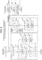
- FIG. 1 illustrates a block diagram of an entire transmission control device controlling an automatic transmission of a vehicle.
- the transmission control device 10 includes a monitoring unit 40 for monitoring the main control unit 30 based on signals from a power supply IC 20, a main control unit 30, and the main control unit 30.
- the transmission control device 10 includes a linear SOL driver 50 for outputting a drive DUTY for hydraulically driving a linear SOL 100 from the main control unit 30 to perform shift control.
- the main control unit 30 includes a relay diagnosis unit 31 for diagnosing the power supply relay 2 for turning ON and OFF the supply of power to the transmission control device 10 and a monitoring unit diagnosis unit 32 for diagnosing the monitoring unit 40, and the monitoring unit 40 includes a monitoring function unit 41, which has a periodic signal monitoring unit 42.
- the power supply IC 20 is connected to a path through which electric power is supplied from the power supply relay 2 without going through the IGNSW 3 and a path through which the electric power is supplied from the battery 1 via the IGNSW 3.
- the key position is changed to the ignition position by the driver, the electric power is supplied from the battery 1 from the path via the IGNSW 3 upon turning ON of the IGNSW 3, so that an En terminal 200 is enabled, whereby the electric power is supplied via a Vin terminal 201 to the power supply IC 20, and as a result, a Vcc 204 starts to be supplied.
- the main control unit 30 and the monitoring unit 40 are activated.
- the main control unit 30 When the main control unit 30 is activated, the main control unit 30 gives an ON instruction to the relay control 203 and turns ON the power supply relay 2 between the battery 1 and the transmission control device 10. When the power supply relay 2 is turned ON, the electric power is started to be supplied to the linear SOL driver 50, so that driving is started.
- the stop operation of the transmission control device 10 is such that when the key position is changed to the OFF position by the driver, the IGNSW 3 turns OFF, and the electric power from the path via IGNSW 3 is no longer supplied, but the electric power is supplied to the transmission control device 10 from the path in which the electric power is supplied from the power supply relay 2 without going through the IGNSW 3, so that the processing can be continued.
- the diagnosis method of the relay diagnosis unit 31 in the main control unit 30 gives an OFF instruction from the main control unit 30 to the relay control 203 at the timing when the key position changes to the OFF position.
- the main control unit 30 determines that the relay is normal if the electric power supplied to the transmission control device 10 stops and the transmission control device 10 can be stopped within a predetermined period of time.
- the main control unit 30 determines that the relay is abnormal if the electric power continues to be supplied to the transmission control device 10 because of the sticking of the power supply relay 2 and the transmission control device 10 keeps on working even after a predetermined period of time elapses. More specifically, the main control unit 30 diagnoses the presence or absence of sticking in the power supply relay by sending an OFF signal to the power supply relay 2.
- the periodic signal 207 transmitted from the main control unit 30 is stopped at the timing when the key position changes to the OFF position, so that the periodic signal monitoring unit 42 in the monitoring unit 40 detects abnormality within a predetermined period of time, and a reset signal 205 is output from the monitoring unit 40 to the main control unit 30.
- the output of the relay control 203 also outputs an "OFF output" which is the initial state, and accordingly, the power supply relay 2 also turns OFF.
- the monitoring unit 40 is determined to be normal.
- the reset signal 205 is not output due to malfunction in the monitoring unit 40, and the transmission control device 10 continues to operate even after a predetermined period of time elapses, the monitoring unit 40 is determined to be abnormal.
- FIG. 2 is a timing chart illustrating relay diagnosis with the relay diagnosis unit 31 and diagnosis of the monitoring unit 40 with the monitoring unit diagnosis unit 32 at the timing when the key position changes to the OFF position. More specifically, in the present embodiment, at the timing when the key position changes to the OFF position, diagnosis of power supply relay 2 with the main control unit 30 or diagnosis of the monitoring unit 40 with the monitoring unit diagnosis unit 32 is performed.
- a selection method for deciding which diagnosis to be carried out at the timing when the key position changes to the OFF position there is a method for preferentially carrying out a diagnosis for a higher malfunction rate on the basis of the malfunction rate of the power supply relay 2 and the malfunction rate of the monitoring unit 40 and carrying out a diagnosis for a lower malfunction rate with a frequency of once in several times.
- it may be configured such that a malfunction occurrence distribution of past products may be analyzed, and the degradation state may be determined from mileage and activation time, and for example, in the first 1000 times, the power supply relay 2 is diagnosed, and the 500 times subsequent thereto, diagnosis of the monitoring unit 40 may be carried out with the monitoring unit diagnosis unit 32.
- a diagnosis for a higher precedence can be set and carried out.
- the vehicle is controlled in the safe direction.
- an OFF instruction is issued to the linear SOL driver 50, and an OFF output is made to the linear SOL 100.
- FIG. 3 is a timing chart in which relay diagnosis with the relay diagnosis unit 31 and diagnosis with the monitoring unit 40 with the monitoring unit diagnosis unit 32 are alternately performed at the timing when the key position changes to the OFF position.
- the relay diagnosis with the relay diagnosis unit 31 and the diagnosis of the monitoring unit 40 with the monitoring unit diagnosis unit 32 are diagnoses for confirming that the transmission control device stops when the electric power supply stops, and therefore, there is an advantage in that the diagnoses are carried out at the timing when the key position changes to the OFF position in such a manner that the relay diagnosis with the relay diagnosis unit 31 and the diagnosis of the monitoring unit 40 with the monitoring unit diagnosis unit 32 are alternately carried out, so that both of the diagnoses can be carried out.
- the diagnosis when malfunction is detected, the user can be immediately notified from the malfunction warning light, and since the vehicle can be controlled in the safe direction after the malfunction occurs, there is an advantage in the improvement of the reliability.
- the second embodiment of the present invention will be described with reference to FIG. 4 and FIG. 5 .
- the present embodiment has an ACCSW 4 in addition to the configuration of the first embodiment.
- FIG. 4 illustrates a block diagram of the entire transmission control device additionally having the ACCSW 4.
- the power supply IC 20 is connected to a path through which electric power is supplied from the power supply relay 2 without going through the IGNSW 3 and the ACCSW 4 and a path through which the electric power is supplied from the battery 1 via the IGNSW 3 and the ACCSW 4.
- the IGNSW 3 and the ACCSW 4 are input as OR, and therefore, when the key position is changed to the ignition position or the accessory position by the driver, the electric power is supplied to the power supply IC 20, and the main control unit 30 and the monitoring unit 40 are activated.
- the main control unit 30 gives an ON instruction to the relay control 203 and turns ON the power supply relay 2 between the battery 1 and the transmission control device 10.
- the power supply relay 2 is turned on, the electric power starts to be supplied to the linear SOL driver 50 via the actuator drive circuit, so that the linear SOL driver 50 starts driving.
- the stop operation of the transmission control device is such that when the driver changes the key position to the accessory position, the IGNSW 3 turns OFF, but ACCSW 4 is in the ON state. Therefore, the supply of power also continues from the path via ACCSW 4. Furthermore, when the key position changes to the OFF position, the IGNSW 3 turns OFF and the electric power from the path via the IGNSW 3 is no longer supplied, but the electric power is supplied to the transmission control device from the path in which the electric power is supplied from the power supply relay 2 without going through the IGNSW 3, and therefore, the processing can be continued.
- the operation mode of the transmission control device changes from the IGN mode to the ACC mode, and predetermined processing is performed, and then the mode is switched to the OFF mode.
- FIG. 5 illustrates a flowchart in which when the key position is in the accessory position, the relay diagnosis with the relay diagnosis unit 31 is carried out, and when the key position is in the OFF position, the diagnosis of the monitoring unit 40 with the monitoring unit diagnosis unit 32 is carried out. More specifically, in the present embodiment, at each of the timing when the key position changes to the OFF position and the timing when the key position changes to the accessory position, any one of the diagnosis of the power supply relay 2 with the main control unit 30 and diagnosis of the monitoring unit 40 with the monitoring unit diagnosis unit 32 is performed.
- the electric power continues to be supplied from the path via the ACCSW 4 even if an OFF instruction of the relay control 203 is given in the signal transmitted from the main control unit 30 to cause the power supply relay 2 to be in the OFF state, and therefore, the diagnosis can be performed without causing the transmission control device 1 to be in the stopped state.
- the battery 1 supplying the electric power to the transmission control device 1 which is the vehicle control device and the power supply relay for turning ON and OFF the supply of the electric power from the battery 1 are provided, and the monitoring unit 40 for monitoring the main control unit 30 on the basis of the signal from the main control unit 30 is provided, and when the key position is in the accessory position, the electric power is supplied from battery 1 to the vehicle control device.
- the method for carrying out the diagnosis of the monitoring unit 40 with the monitoring unit diagnosis unit 32 and the relay diagnosis unit 31 and the control during abnormality detection are shown in the flowchart of FIG. 6 .
- the key position is determined.
- the relay diagnosis is performed.
- an OFF instruction for turning OFF the relay port is issued, and the timeout determination is carried out in S1002.
- the voltage is measured from the voltage monitor 202.
- a voltage drop is determined. If the voltage drops by more than a specified value, the power supply relay 2 is determined to be in the OFF state, and in step S1005, the relay diagnosis is determined to be OK.
- S1002 is performed back again to repeat the diagnosis. If the voltage does not drop even after a specified time elapses in S1002, the relay diagnosis is determined to be NG in S1006 as a transition of timeout, and the malfunction warning light is turned ON in S1007, and malfunction information is stored in S1008. After determining OK/NG of the relay diagnosis, an ON instruction for turning ON the relay port is issued in S1007 and the diagnosis is terminated.
- An example of periodic signal monitoring function includes a watchdog timer. More specifically, as an example of the monitoring unit 40, there is a watchdog timer for monitoring the presence or absence of abnormality in the main control unit 30 by receiving a signal sent from main control unit 30 with a predetermined interval, and transmitting a reset signal to the main control unit 30 when abnormality of the main control unit 30 is detected.
- the diagnosis processing of the watchdog timer function stops the periodic signal (P-RUN) 207 transmitted from the main control unit 30 in S2001, and a determination is made as to whether the periodic signal monitoring unit 42 in the monitoring unit 40 detects abnormality within a predetermined period of time or not in S2002.
- the monitoring unit 40 outputs a reset signal 205 to the main control unit 30, so that the power supply to the transmission control device 10 stops and the transmission control device 10 stops. If the reset signal 205 is not output due to malfunction in the monitoring unit 40, and a predetermined period of time has elapsed, then, the diagnosis of the watchdog timer function is determined to be NG in S2003.
- step S2004 the malfunction warning light is turned on, and in step S2005, processing for storing malfunction information is executed, and the processing is terminated.
- any of the relay diagnosis with the relay diagnosis unit 31 and the diagnosis of the monitoring unit 40 with the monitoring unit diagnosis unit 32 is carried out.
- the previous diagnosis result is determined in S3001, and only in a case where "diagnosis NG" is stored, the malfunction warning lamp is turned ON in S3002, and in step S3003, as a control for abnormality, an instruction to turn OFF the output of the linear SOL is issued.
- any one of the diagnosis i.e., the relay diagnosis with the relay diagnosis unit 31 and the diagnosis of the monitoring unit 40 with the monitoring unit diagnosis unit 32, can be carried out until the key position is changed to the OFF state. Furthermore, as a result of diagnosis, when malfunction is detected, the user can be immediately notified from the malfunction warning light without waiting for the subsequent key-on. When malfunction is stored at the subsequent key-on, an OFF instruction is issued to the linear SOL driver 50, and the linear SOL 100 is set to the OFF output, so that there is an advantage in that the vehicle can be controlled in the safe direction, whereby the reliability can be improved.
Landscapes
- Engineering & Computer Science (AREA)
- General Engineering & Computer Science (AREA)
- Mechanical Engineering (AREA)
- Control Of Transmission Device (AREA)
- Selective Calling Equipment (AREA)
- Electric Propulsion And Braking For Vehicles (AREA)
Applications Claiming Priority (2)
| Application Number | Priority Date | Filing Date | Title |
|---|---|---|---|
| JP2015135746 | 2015-07-07 | ||
| PCT/JP2016/068452 WO2017006762A1 (fr) | 2015-07-07 | 2016-06-22 | Dispositif de commande de véhicule |
Publications (2)
| Publication Number | Publication Date |
|---|---|
| EP3321135A1 true EP3321135A1 (fr) | 2018-05-16 |
| EP3321135A4 EP3321135A4 (fr) | 2019-03-13 |
Family
ID=57685116
Family Applications (1)
| Application Number | Title | Priority Date | Filing Date |
|---|---|---|---|
| EP16821232.2A Withdrawn EP3321135A4 (fr) | 2015-07-07 | 2016-06-22 | Dispositif de commande de véhicule |
Country Status (5)
| Country | Link |
|---|---|
| US (1) | US20180119804A1 (fr) |
| EP (1) | EP3321135A4 (fr) |
| JP (1) | JP6469225B2 (fr) |
| CN (1) | CN107709101A (fr) |
| WO (1) | WO2017006762A1 (fr) |
Families Citing this family (6)
| Publication number | Priority date | Publication date | Assignee | Title |
|---|---|---|---|---|
| JP6887277B2 (ja) * | 2017-03-24 | 2021-06-16 | 日立Astemo株式会社 | 自動車用電子制御装置 |
| JP6963358B2 (ja) * | 2018-03-26 | 2021-11-10 | 株式会社エンビジョンAescジャパン | 電源装置 |
| CN108839624B (zh) * | 2018-06-28 | 2020-10-30 | 潍柴动力股份有限公司 | 汽车点火开关控制系统及方法 |
| DE112020000815T5 (de) * | 2019-03-26 | 2021-10-28 | Hitachi Astemo, Ltd. | Elektronische steuerungseinrichtung und diagnoseverfahren einer elektronischen steuerungseinrichtung |
| JPWO2020217928A1 (fr) * | 2019-04-25 | 2020-10-29 | ||
| CN112065984B (zh) * | 2020-08-21 | 2021-08-06 | 安徽江淮汽车集团股份有限公司 | 变速箱选换挡系统故障诊断方法、装置、设备及存储介质 |
Family Cites Families (16)
| Publication number | Priority date | Publication date | Assignee | Title |
|---|---|---|---|---|
| JP3097580B2 (ja) * | 1996-12-18 | 2000-10-10 | 株式会社デンソー | 電子制御装置 |
| JP3488086B2 (ja) * | 1998-05-26 | 2004-01-19 | 株式会社日立製作所 | エンジン制御装置および制御方法 |
| JP3651273B2 (ja) * | 1998-08-20 | 2005-05-25 | 日産自動車株式会社 | セルフシャットオフ機能の診断装置 |
| JP2000136871A (ja) * | 1998-11-04 | 2000-05-16 | Nissan Motor Co Ltd | 自動変速機用コントロールユニットの暴走監視装置 |
| JP2003004132A (ja) * | 2001-06-25 | 2003-01-08 | Aisin Seiki Co Ltd | 負荷駆動装置 |
| JP4007038B2 (ja) * | 2002-03-29 | 2007-11-14 | 株式会社デンソー | 車両用電子制御装置 |
| JP4692318B2 (ja) * | 2005-04-20 | 2011-06-01 | 株式会社デンソー | 電子制御装置 |
| JP2006316638A (ja) * | 2005-05-10 | 2006-11-24 | Denso Corp | メインリレー故障診断方法及び電子制御装置 |
| JP4500215B2 (ja) * | 2005-06-01 | 2010-07-14 | 株式会社東海理化電機製作所 | 車両の始動判定装置及びそれを備えた遠隔制御装置 |
| JP5060756B2 (ja) * | 2006-09-29 | 2012-10-31 | パナソニック株式会社 | 車両電源制御装置 |
| JP5240260B2 (ja) * | 2010-09-13 | 2013-07-17 | 株式会社デンソー | 車両用電子制御装置 |
| JP5906978B2 (ja) * | 2012-07-19 | 2016-04-20 | 株式会社デンソー | 自動変速機の制御装置 |
| JP5983171B2 (ja) * | 2012-08-10 | 2016-08-31 | 株式会社Gsユアサ | スイッチ故障診断装置、蓄電装置 |
| JP2014035730A (ja) * | 2012-08-10 | 2014-02-24 | Hitachi Automotive Systems Ltd | 車両用制御装置 |
| JP6244110B2 (ja) * | 2013-05-31 | 2017-12-06 | 日本電産エレシス株式会社 | 電子制御装置 |
| JP6364486B2 (ja) * | 2014-06-18 | 2018-07-25 | 日立オートモティブシステムズ株式会社 | 車載制御装置または車載制御システム |
-
2016
- 2016-06-22 US US15/573,263 patent/US20180119804A1/en not_active Abandoned
- 2016-06-22 JP JP2017527165A patent/JP6469225B2/ja active Active
- 2016-06-22 WO PCT/JP2016/068452 patent/WO2017006762A1/fr active Application Filing
- 2016-06-22 CN CN201680036571.8A patent/CN107709101A/zh active Pending
- 2016-06-22 EP EP16821232.2A patent/EP3321135A4/fr not_active Withdrawn
Also Published As
| Publication number | Publication date |
|---|---|
| US20180119804A1 (en) | 2018-05-03 |
| CN107709101A (zh) | 2018-02-16 |
| JP6469225B2 (ja) | 2019-02-13 |
| WO2017006762A1 (fr) | 2017-01-12 |
| JPWO2017006762A1 (ja) | 2018-03-01 |
| EP3321135A4 (fr) | 2019-03-13 |
Similar Documents
| Publication | Publication Date | Title |
|---|---|---|
| EP3321135A1 (fr) | Dispositif de commande de véhicule | |
| US20140188359A1 (en) | Electric brake assist system for vehicle use | |
| EP3444624A1 (fr) | Appareil et procédé permettant de diagnostiquer une défaillance de relais d'une batterie à l'aide d'un circuit parallèle pour une alimentation électrique régulière | |
| US20070055908A1 (en) | Redundant power supply circuit and motor driving circuit | |
| US20170146118A1 (en) | Vehicle-Mounted Control Device or Vehicle-Mounted Control System | |
| JP4747705B2 (ja) | 車載電流センサの故障診断装置 | |
| JP2006322362A (ja) | エンジン自動停止始動制御装置 | |
| JP2007024825A (ja) | 電流センサの故障診断装置 | |
| US5677839A (en) | On-vehicle electronic control device and a method of detecting a failure thereof | |
| US9547569B2 (en) | Electronic control unit for vehicle | |
| JP2018057218A (ja) | 非常停止用スイッチの故障診断装置、方法、プログラム及び電動移動体 | |
| US11979095B2 (en) | Discharge control circuit and power conversion device | |
| CN102485544A (zh) | 扭矩传感器故障检测装置和方法 | |
| US20160075252A1 (en) | Monitoring device for a vehicle and method for monitoring a vehicle | |
| JP7014140B2 (ja) | 電磁ブレーキ制御装置及び制御装置 | |
| JP2009196453A (ja) | スイッチ手段の故障検出装置 | |
| JP2017093008A (ja) | コンタクタ故障判定装置およびコンタクタ故障判定方法 | |
| CN108369879B (zh) | 用于监视冗余互连触点的功能的方法和装置 | |
| EP3808152B1 (fr) | Circuit électrique et procédé de diagnostic pour charge électrique | |
| US20210163028A1 (en) | System for automatically monitored signalling of a vehicle state and method for monitoring a vehicle state-signalling device | |
| JP6394183B2 (ja) | 非常用スイッチの診断装置および変速制御システム | |
| JP2007262934A (ja) | 車両用制御装置 | |
| JP4859537B2 (ja) | 中継器 | |
| JP6473072B2 (ja) | 車両制御装置 | |
| JP2006151560A (ja) | 乗客コンベアの制御装置 |
Legal Events
| Date | Code | Title | Description |
|---|---|---|---|
| STAA | Information on the status of an ep patent application or granted ep patent |
Free format text: STATUS: THE INTERNATIONAL PUBLICATION HAS BEEN MADE |
|
| PUAI | Public reference made under article 153(3) epc to a published international application that has entered the european phase |
Free format text: ORIGINAL CODE: 0009012 |
|
| STAA | Information on the status of an ep patent application or granted ep patent |
Free format text: STATUS: REQUEST FOR EXAMINATION WAS MADE |
|
| 17P | Request for examination filed |
Effective date: 20180207 |
|
| AK | Designated contracting states |
Kind code of ref document: A1 Designated state(s): AL AT BE BG CH CY CZ DE DK EE ES FI FR GB GR HR HU IE IS IT LI LT LU LV MC MK MT NL NO PL PT RO RS SE SI SK SM TR |
|
| AX | Request for extension of the european patent |
Extension state: BA ME |
|
| DAV | Request for validation of the european patent (deleted) | ||
| DAX | Request for extension of the european patent (deleted) | ||
| A4 | Supplementary search report drawn up and despatched |
Effective date: 20190212 |
|
| RIC1 | Information provided on ipc code assigned before grant |
Ipc: F16H 61/02 20060101ALI20190206BHEP Ipc: F16H 61/12 20100101ALI20190206BHEP Ipc: B60R 16/02 20060101AFI20190206BHEP |
|
| STAA | Information on the status of an ep patent application or granted ep patent |
Free format text: STATUS: EXAMINATION IS IN PROGRESS |
|
| STAA | Information on the status of an ep patent application or granted ep patent |
Free format text: STATUS: EXAMINATION IS IN PROGRESS |
|
| 17Q | First examination report despatched |
Effective date: 20210421 |
|
| STAA | Information on the status of an ep patent application or granted ep patent |
Free format text: STATUS: THE APPLICATION IS DEEMED TO BE WITHDRAWN |
|
| 18D | Application deemed to be withdrawn |
Effective date: 20210902 |