EP3317106B1 - Siebdruckvorrichtung und verfahren zum siebdrucken - Google Patents
Siebdruckvorrichtung und verfahren zum siebdrucken Download PDFInfo
- Publication number
- EP3317106B1 EP3317106B1 EP16733517.3A EP16733517A EP3317106B1 EP 3317106 B1 EP3317106 B1 EP 3317106B1 EP 16733517 A EP16733517 A EP 16733517A EP 3317106 B1 EP3317106 B1 EP 3317106B1
- Authority
- EP
- European Patent Office
- Prior art keywords
- printing
- squeegee
- screen
- articulated arm
- robot
- Prior art date
- Legal status (The legal status is an assumption and is not a legal conclusion. Google has not performed a legal analysis and makes no representation as to the accuracy of the status listed.)
- Not-in-force
Links
Images


Classifications
-
- B—PERFORMING OPERATIONS; TRANSPORTING
- B41—PRINTING; LINING MACHINES; TYPEWRITERS; STAMPS
- B41F—PRINTING MACHINES OR PRESSES
- B41F15/00—Screen printers
- B41F15/08—Machines
- B41F15/0804—Machines for printing sheets
- B41F15/0813—Machines for printing sheets with flat screens
- B41F15/0818—Machines for printing sheets with flat screens with a stationary screen and a moving squeegee
-
- B—PERFORMING OPERATIONS; TRANSPORTING
- B41—PRINTING; LINING MACHINES; TYPEWRITERS; STAMPS
- B41F—PRINTING MACHINES OR PRESSES
- B41F15/00—Screen printers
- B41F15/08—Machines
- B41F15/0881—Machines for printing on polyhedral articles
-
- B—PERFORMING OPERATIONS; TRANSPORTING
- B41—PRINTING; LINING MACHINES; TYPEWRITERS; STAMPS
- B41F—PRINTING MACHINES OR PRESSES
- B41F15/00—Screen printers
- B41F15/08—Machines
- B41F15/0895—Machines for printing on curved surfaces not otherwise provided for
-
- B—PERFORMING OPERATIONS; TRANSPORTING
- B41—PRINTING; LINING MACHINES; TYPEWRITERS; STAMPS
- B41F—PRINTING MACHINES OR PRESSES
- B41F15/00—Screen printers
- B41F15/14—Details
- B41F15/16—Printing tables
- B41F15/18—Supports for workpieces
-
- B—PERFORMING OPERATIONS; TRANSPORTING
- B41—PRINTING; LINING MACHINES; TYPEWRITERS; STAMPS
- B41F—PRINTING MACHINES OR PRESSES
- B41F15/00—Screen printers
- B41F15/14—Details
- B41F15/16—Printing tables
- B41F15/18—Supports for workpieces
- B41F15/30—Supports for workpieces for articles with curved surfaces
-
- B—PERFORMING OPERATIONS; TRANSPORTING
- B41—PRINTING; LINING MACHINES; TYPEWRITERS; STAMPS
- B41F—PRINTING MACHINES OR PRESSES
- B41F15/00—Screen printers
- B41F15/14—Details
- B41F15/34—Screens, Frames; Holders therefor
- B41F15/38—Screens, Frames; Holders therefor curved
-
- B—PERFORMING OPERATIONS; TRANSPORTING
- B41—PRINTING; LINING MACHINES; TYPEWRITERS; STAMPS
- B41F—PRINTING MACHINES OR PRESSES
- B41F15/00—Screen printers
- B41F15/14—Details
- B41F15/44—Squeegees or doctors
- B41F15/46—Squeegees or doctors with two or more operative parts
Definitions
- the invention relates to a screen printing device with a printing screen, a squeegee and a support for a printing material to be printed.
- the invention also relates to a method for screen printing with a screen printing device according to the invention.
- a squeegee for printing curved surfaces known.
- the squeegee has a holding portion to which the squeegee rubber is attached, wherein the holding portion consists of several individual sections, which are interconnected by means of the squeegee rubber and thus flexible.
- the squeegee rubber can be cut according to the contour of the printed material to be printed.
- a screen printing device in which an upper work is guided in slide guides and thereby can be pivoted during a pressure movement of the doctor blade relative to a printing material to be printed.
- the link guides must be matched to the curvature of each printed material to be printed.
- the upper work by means of four adjusting cylinders pivotally to a support for a printing material to be printed. Via a control unit, the pivoting movement of the upper work can then be adjusted during the doctor blade movement adapted to the curvature of the printed material to be printed.
- a screen-printing squeegee which has a flexible holding section and a squeegee rubber connected to the holding section.
- the holding section consists of several, elastically interconnected individual sections.
- Several of the individual sections are connected to an adjusting cylinder, which in turn are attached to a squeegee bar.
- a device for screen printing on the inside of a curved substrate is known.
- the substrate may be, for example, a motor vehicle window.
- a squeegee is fastened to a pivotably mounted arm and as a result retains a fixed predetermined curved path, which corresponds to the course of the inside of the curved substrate.
- the US patent publication US 2008/0202364 A1 describes a squeegee for screen printing.
- the squeegee is viewed transversely to the pressure direction elastically formed and connected by means of several, hingedly interconnected sections with a doctor blade holder.
- the doctor edge can thereby adapt to a curved course of a substrate to be printed.
- a screen printing device and a method for screen printing in terms of flexibility in printing curved printed material to be improved.
- a screen printing device with the features of claim 1 is provided for this purpose. It is a screen printing device provided with a printing screen, a squeegee and a support for a printing material to be printed, in which at least one articulated arm robot is provided for moving the squeegee and / or the support relative to the printing screen.
- the squeegee and / or the support can be freely programmably guided along the printing screen.
- curved printing material in particular three-dimensionally curved printed material, can be printed with high precision and the printing of differently curved printed material requires only a reprogramming of the movement sequence of the articulated-arm robot.
- the screen printing device can be used in an extremely flexible manner.
- the movement of the support by means of the articulated arm robot must be synchronized with the movement of the squeegee.
- the squeegee can be moved in an upper work by means of a squeegee parallel to the printing screen.
- the squeegee is moved by means of the articulated-arm robot, then the articulated-arm robot with the squeegee follows the contour of the printed item to be printed. It is also provided in the context of the invention that both the support and the squeegee are moved by means of a respective Gelenkarmroboters.
- the screen printing device according to the invention is also advantageous when printing flat printing material, since the trajectory of the squeegee or a flood squeegee can be chosen freely.
- the diagonal doctoring or circular doctor blades may be useful or a flood doctor blade is not linear but moved so that the color is held in the screen at the desired locations.
- the invention makes any movements of doctor blades possible.
- the articulated-arm robot is designed as a multi-axis robot, in particular a 5-axis robot or a 6-axis robot.
- the articulated robot must have at least 3 axes.
- the squeegee is connected to a movable robot hand of an articulated arm robot.
- the contour of a curved, to be printed printing material can be easily followed.
- the movement of the squeegee can be optimally adjusted, but also an angle of the squeegee to each just touched surface portion of the printed material can be optimally adjusted.
- the support is connected to a movable robot hand of a Gelenkarmroboters.
- the support can be moved or pivoted relative to the printing screen with the print material to be printed thereon attached. This must be synchronized with a movement of the squeegee, wherein the support is in particular pivoted so that a tangent to the straight with the printing screen or the squeegee contacting surface portions is always parallel to the direction of movement of the squeegee. In this way, an optimal print result can be ensured.
- the squeegee is connected to a first articulated-arm robot and the support is connected to a second articulated-arm robot.
- an extremely flexible screen printing device which can also be adapted to three-dimensionally multi-curved printed matter.
- an upper work is provided with receiving devices for the printing screen and with a slidable along the upper work squeegee on which the squeegee is arranged, wherein the support is moved by means of Gelenkarmroboters relative to the printing screen and in a manner adapted to the movement of the squeegee.
- a conventional upper work which has holders for printing screens and a drive for the doctor bar to which the squeegee is attached. Only the support for the print material is held by means of an articulated arm robot and the articulated arm robot moves the support with the print material synchronized with the doctor blade, so that each optimum angle and contact pressure between the squeegee, the printing screen and the printing material to be printed during the entire course of the printing process is available.
- a contact angle of the squeegee relative to the contact surface of the printing material to be printed with the printing screen during movement of the squeegee in a predetermined angular range, in particular constant, held, this being done by moving the support relative to the printing screen.
- the contact angle and also the contact pressure of the squeegee can be kept in an optimum range or to an optimum value.
- a doctor bar is arranged on the robot hand of the articulated arm robot, and the pressure doctor is connected to the doctor bar by means of a plurality of adjusting cylinders.
- the squeegee is guided by means of the articulated arm robot on a path that follows the contour of the printed material to be printed.
- an optimum for printing the print good trajectory of the squeegee can be adjusted. Since an articulated arm robot is used to guide the squeegee, the trajectory can be changed in any way to adapt the trajectory to a changed contour of the printed material to be printed or, depending on the existing boundary conditions, to obtain an optimal printing result.
- the squeegee has a flexible holding section and a squeegee rubber fastened to the holding section, wherein a course of the holding section and of the squeegee rubber can be changed by means of the adjusting cylinder.
- the course of the squeegee rubber can be adapted to a contour of the printed material to be printed.
- the squeegee is thereby guided along a movement path, which is adapted to the curvature of the print material in the printing direction.
- the course of the squeegee or squeegee rubber can be adapted to a curvature of the printed matter perpendicular to the printing direction.
- a flood squeegee is arranged on the robot hand of the articulated arm robot.
- the required before the actual printing movement of the flood blade for distributing ink or printing paste on the printing screen can be done by means of Gelenkarmroboters and thereby with a freely programmable trajectory. It is quite intended that the trajectory of the flood squeegee differs from the trajectory of the squeegee, with different trajectories of squeegee and flood squeegee are not essential and are adjusted depending on the prevailing boundary conditions.
- the problem underlying the invention is also solved by a method for screen printing with a screen printing device according to the invention, wherein the movement of the squeegee and / or the support are provided by means of a Gelenkarmroboters relative to the printing screen during a printing operation.
- changing a squeegee pressure on the object to be printed and / or changing a squeegee angle relative to the printing screen by means of the articulated arm robot during movement of the squeegee is provided relative to the printing screen.
- the tilting of the squeegee is provided about a rotational axis parallel to the direction of movement of the squeegee during movement of the squeegee relative to the printing screen.
- the position of the squeegee can be adapted to the curvature of the print material to be printed.
- Such tilting movements of the squeegee are required in complicated curved print material to achieve an optimum printing result and can be realized easily with the articulated arm robot of the screen printing device according to the invention.
- teaching a trajectory of the squeegee and / or the support by means of approaching individual points and then interpolating a trajectory and storing the trajectory in a control unit of at least one Gelenkarmroboters is provided.
- a required trajectory can be generated in a CAD system, stored and transferred to the control unit of the at least one articulated arm robot.
- settings and trajectories required for the optimal printing of a curved printing material of the screen printing device according to the invention can be called up quickly and in a flexible manner.
- These settings may include, for example, a printing screen to be used as well as a possible movement of the printing screen during the printing process, a so-called Sieblift. If the screen printing device is then to be converted to print another print, the required settings can all be removed from the control unit, so that a conversion can be done easily and possibly even fully automatically.
- the presentation of the Fig. 1 shows a screen printing apparatus 10 according to a first embodiment of the invention.
- the screen printing apparatus 10 has an upper work 12 with a printing screen 14 and a in Fig. 1 concealed squeegee 14 on.
- the squeegee 14 is connected by means of three adjusting cylinders 16 with a squeegee bar 18 which is slidably guided in two lateral guides 20 of the upper work 12.
- drive devices of the doctor bar 18 along the guides 20 are moved back and forth.
- a flood squeegee which in the representation of Fig. 1 is not recognizable.
- the floater is intended to distribute evenly on the printing screen 14 applied ink or printing paste before the start of the actual printing process.
- the printing screen 14 is provided with a screen frame 22 which can be pivoted relative to the guides 20 and thus relative to the doctor bar 18 with the squeegee 14 slightly. As a result, a so-called Sieblift during the movement of the squeegee 14 via the printing screen 24 can be achieved.
- the upper work 12 is connected by means of only schematically indicated holding devices 26 with a base, such as a hall floor.
- the guides 20 are thus immovably arranged in the room during the printing process, but can of course be removed or moved, for example, for maintenance or the like.
- the screen printing device 10 further has a support 28 for printing material 30 to be printed.
- the printing material 30 is in Fig. 1 for example, a one-dimensionally curved disk.
- the disc or the print material 30 rests on a suitably curved surface of the support 28, which is also referred to as a mask.
- the support 28 is disposed below the printing screen 24, wherein in the state of Fig. 1 the print material 30 is not applied to the printing screen 24.
- the Fig. 1 thus shows a state even before the actual printing process.
- the screen printing device 10 is further provided with an articulated arm robot 32 which is fixed with its base 34, for example on a hall floor. On a robot hand 36 of the articulated arm robot 32, the support 28 is attached. The support 28 can thus arbitrarily in space be moved and specifically any path of movement in space with the support 28 are performed.
- the articulated arm robot 32 is formed in the illustrated embodiment as a 6-axis robot.
- the articulated arm robot 32 it is possible to move the support 28 in a coordinated manner during the movement of the squeegee 14 along the guides 20, so that the print material 30 is synchronized with the movement of the squeegee 14.
- the support 28 is rotated so that the squeegee 14 and the printing screen 24 each contacted only an approximately linear portion of the printed matter 30.
- the support 30 or the print material 30 is then unrolled on the printing screen 24, so that always an optimal angle between the printing material 30, the printing screen 24 and the squeegee 14 can be adjusted.
- the case performed by the support 28 movement is freely programmable in space.
- the embodiment shown with the one-dimensionally curved printing material 30 is a comparatively easy-to-use application. With the screen printing device 10 according to the invention, however, optimal results can also be achieved if the printed material is curved, for example, in several directions. With the articulated arm 32 can still be adjusted for the printing optimal trajectory of the support 28 during the movement of the squeegee 14.
- a central control unit 38 is shown, via which both the articulated arm robot 32 and the upper work 12 can be controlled.
- the control unit 38 an optimal for the print material 30 trajectory is stored and beyond the adjustment parameters of the upper work 12 can be stored, for example doctor blade angle, contact pressure, Sieblift, movement speed of the squeegee 14, applied amount of paint and the like.
- the support 28 When changing to a print material 30 differently shaped print material then only the support 28 must be changed and stored in the control unit 38 settings, including trajectories for the new printing material are the articulated arm robot 32 and the upper work 12 passed to a quick change to the new To allow printing material.
- the representations of the Fig. 2 . 3 and 4 show the screen printing apparatus 10 of Fig. 1 in sections in different states during a printing process.
- the articulated arm robot 32 can be seen in sections.
- the support 28 and thus also in Fig. 2 unrecognizable print material in a tilted Position, in Fig. 2 tilted down to the left, arranged.
- the support 28 is arranged so that the printed matter immediately below the in Fig. 2 unrecognizable pressure screen 14 is arranged.
- Fig. 2 is only a screen frame 40 to recognize, which is held on the upper work 12 and on which the printing screen 14 is arranged.
- the squeegee bar 18 with the squeegee is in a first state at the beginning of a movement along the guides 20 from left to right.
- the squeegee 18 is in the state shown at an in Fig.
- the printing screen is brought into contact with the print material in the region of the printing position. While starting from the state of Fig. 2 to the left progressing movement of the doctor blade bar 18 with the squeegee disposed thereon, the squeegee passes over the printing screen and presses ink through openings in the printing screen 14 on the print material on the support 28th
- the in Fig. 3 shown reached second state during the printing process.
- the support 28 is now synchronous with the movement of the doctor blade bar 18 with the attached squeegee starting from the state of Fig. 2 swung clockwise.
- the printing screen 14 facing surface of the support 28 was unrolled on the printing screen 14 in such a way that the squeegee is always located on the highest point of the printed matter on the support 28.
- the support 28 is pivoted so that a tangent to the contact line between the squeegee and the print material 30 is always parallel to the direction of movement of the squeegee.
- the direction of movement of the squeegee takes place in the Fig. 2 to 4 from right to left.
- Fig. 4 shows a third state during the printing process.
- the squeegee bar 18 with the squeegee has now moved so far to the left that he has reached the left end of the print on the support 28.
- the edition 28 was based on the state of Fig. 3 further pivoted clockwise.
- the programming of the articulated arm robot 32 can be done either by importing data that has been generated, for example, by means of a CAD system.
- the programming can also be done by means of a so-called learning process. For example, in the Fig. 2 . 3 and 4 approached states stored and stored.
- the control unit 38 then performs an interpolation between the individual points on the trajectory and then stores the trajectory.
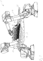
- FIG. 5 shows a second embodiment of a screen printing device 50 according to the invention.
- a printing screen 56 is attached to a screen frame 58.
- the screen frame 58 is connected by means of only schematically indicated adjusting cylinder 60 with the hall floor or other base.
- four adjusting cylinders 60 are provided at the corners of the screen frame 58, wherein in Fig. 5 for the sake of clarity, only two are shown.
- the adjusting cylinders 60 are provided to raise the screen frame 58 with the printing screen 56, if necessary, slightly, in order to achieve, for example, during the printing process, a screen lift. As a rule, the adjusting cylinders 60 are not provided for biasing the printing screen 56 in the direction of the printing material 54 in order thereby to adapt the printing screen to the contour of the printed material 54.
- the printing screen 56 is only in the area in contact with the printing material 54, where it is pressed by a squeegee rubber 62 of a squeegee 64 on the print material 54.
- the screen fabric of the printing screen 56 is elastic enough to be pressed during the printing operation of the squeegee 64 on the print material to be printed 54.
- arched screens may be used in which the screen frame and the screen fabric of Druckgutkontur are bent accordingly.
- the squeegee 64 is attached to the robot hand of the articulated arm robot 50 and is moved by means of the articulated arm robot 50 along a movement path which follows substantially the contour of the print material 54 in the printing direction.
- the printing direction runs in the representation of Fig. 5 along the arrow 66, ie from top left to bottom right.
- the squeegee 64 is designed as a flexible squeegee. Specifically, the squeegee rubber 62 is received in a flexible holding portion 68. The holding portion 68 can thereby take a curved course in a direction perpendicular to the printing direction 66 together with the squeegee rubber 62. In contrast to the pressure direction 66, the holding section 68 is comparatively stiff. The holding section 68 is connected to the squeegee bar 72 with a total of nine adjusting cylinders 70.
- a desired curved course of the squeegee rubber 62 can be adjusted, which is adapted to the curvature of the print material 54 perpendicular to the printing direction 66.
- a curvature of the squeegee rubber 62 can be adjusted during the movement of the squeegee 64 in the printing direction 66, thereby adapting to a possibly changing curvature of the print material 54 to achieve.
- the trajectory of the squeegee 64 is adjusted by means of the articulated arm robot 50 a curvature of the print material 54 parallel to the printing direction 66.
- the presentation of the Fig. 6 shows the screen printing device 50 sections in a first state at the beginning of a printing operation.
- the printing screen 56 is shown schematically and the squeegee rubber 62 of the squeegee 64 presses the printing screen 56 on the curved support 52 and on the printing material 54.
- the printing screen 56 is elastic to join this strain. It is Fig. 6 it can be seen that the squeegee rubber 62 only rests on the printing screen 56 and indirectly on the printing material 54 with its edge lying in the direction of printing 66.
- the squeegee 64 is thus always adjusted slightly inclined to the printing material 54. A corresponding angle is maintained by means of the articulated arm robot 72 during the entire movement of the squeegee 64 over the printing material 54 to be printed.
- the presentation of the Fig. 7 shows the screen printing device 50 in a second state during the printing process.
- the squeegee 64 has now been further moved by means of the Gelenkarmroboters 72 in the printing direction on the print material to be printed 54, for example, a curved vehicle window, wherein the Gelenkarmroboter 72 follows the curvature of the print material 54 in the printing direction 66.
- a curvature of the squeegee rubber 62 is adapted to the curvature of the printed matter 54 perpendicular to the printing direction 66 by means of the adjusting cylinder 70.
- the screen printing device 50 according to the invention makes it possible to optimally contact the squeegee rubber 62 on the printing screen (not shown) or indirectly on the printing material 54 during the entire printing process.
- Fig. 8 shows a third state of the screen printing device 50 according to the invention shortly before completion of the printing operation.
- the Gelenkarmroboter 72 has the squeegee 64 now until shortly before in Fig. 8 right end of the print 54 moves. The printing process is almost complete.
- a flood blade 76 is arranged on the doctor bar 72 in addition to the squeegee 64 yet.
- the floater blade 76 serves to evenly distribute printing ink or printing paste over the printing screen before the actual printing process.
- the flood blade 76 can also be moved relative to the printing screen 56 by means of the articulated arm robot 74 in any desired movement path which can be fixed freely in space. For example, this is done Flooding with the flood squeegee 76 in the in Fig. 5
- the articulated arm robot 74 guides the floats 76 in a straight line and parallel to the printing screen 56. In the actual printing operation, the printing blade 64 is then moved over the curvature of the printing stock 54 as described.
- the presentation of the Fig. 9 shows a screen printing device 80 according to the invention according to another embodiment of the invention.
- the screen printing apparatus 80 represents a combination of the screen printing apparatuses 10 of FIGS Fig. 1 to 4 and the screen printing apparatus 50 of the Fig. 5 to 8 Identically formed components are therefore not explained.
- the curved print material 30 is mounted on the support 28 and, as in the screen printing apparatus 10, the support 28 is moved by means of the articulated arm robot 32 synchronously with the movement of the squeegee 64 on the printing screen 56.
- the squeegee 64 as in the screen printing device 50, attached to the robot hand of the articulated arm robot 74.
- the two articulated arm robots 32, 74 carry out coordinated movements of the support 28 or the squeegee 64 in order to optimally print the print material 30.
- the printing screen 56 with the screen frame 58 is arranged as in the screen printing device 50. In principle, the screen frame 58 is thus fixed in space, only to achieve a so-called screen lift the screen frame 58 can be easily raised during the printing process, as already explained with reference to the screen printing device 50.
- the screen printing device 80 allows extremely flexible use for a wide variety of print products. Both the movement of the support 28 and the movement of the squeegee 64 and the flood blade 76 are freely programmable and can be optimally adapted to the particular application.
Landscapes
- Engineering & Computer Science (AREA)
- Mechanical Engineering (AREA)
- Screen Printers (AREA)
Priority Applications (1)
| Application Number | Priority Date | Filing Date | Title |
|---|---|---|---|
| PL16733517T PL3317106T3 (pl) | 2015-07-03 | 2016-06-29 | Urządzenie do sitodruku i sposób drukowania sitowego |
Applications Claiming Priority (2)
| Application Number | Priority Date | Filing Date | Title |
|---|---|---|---|
| DE102015212515.7A DE102015212515A1 (de) | 2015-07-03 | 2015-07-03 | Siebdruckvorrichtung und Verfahren zum Siebdrucken |
| PCT/EP2016/065151 WO2017005576A1 (de) | 2015-07-03 | 2016-06-29 | Siebdruckvorrichtung und verfahren zum siebdrucken |
Publications (2)
| Publication Number | Publication Date |
|---|---|
| EP3317106A1 EP3317106A1 (de) | 2018-05-09 |
| EP3317106B1 true EP3317106B1 (de) | 2019-05-01 |
Family
ID=56292716
Family Applications (1)
| Application Number | Title | Priority Date | Filing Date |
|---|---|---|---|
| EP16733517.3A Not-in-force EP3317106B1 (de) | 2015-07-03 | 2016-06-29 | Siebdruckvorrichtung und verfahren zum siebdrucken |
Country Status (6)
| Country | Link |
|---|---|
| US (1) | US20180186147A1 (pl) |
| EP (1) | EP3317106B1 (pl) |
| DE (1) | DE102015212515A1 (pl) |
| HU (1) | HUE043635T2 (pl) |
| PL (1) | PL3317106T3 (pl) |
| WO (1) | WO2017005576A1 (pl) |
Families Citing this family (6)
| Publication number | Priority date | Publication date | Assignee | Title |
|---|---|---|---|---|
| WO2019031206A1 (ja) * | 2017-08-10 | 2019-02-14 | マイクロ・テック株式会社 | スクリーン印刷装置及びスクリーン印刷方法 |
| JP6955716B2 (ja) * | 2017-08-10 | 2021-10-27 | マイクロ・テック株式会社 | スクリーン印刷装置及びスクリーン印刷方法 |
| JP7054131B2 (ja) | 2017-08-10 | 2022-04-13 | マイクロ・テック株式会社 | スクリーン印刷装置及びスクリーン印刷方法 |
| DE102017215745A1 (de) | 2017-09-07 | 2019-03-07 | Koenig & Bauer Ag | Verfahren zum Betreiben einer Druckmaschine |
| DE102018124754B4 (de) * | 2018-10-08 | 2022-03-24 | Koenig & Bauer Ag | Siebdruckvorrichtung mit einer Siebdruckschablone und mit mindestens zwei am Druckprozess beteiligten Rakelsystemen |
| CN111702782B (zh) * | 2020-06-29 | 2022-07-19 | 重庆大学 | 一种换电机器人举升装置结构及控制参数协同优化方法 |
Family Cites Families (18)
| Publication number | Priority date | Publication date | Assignee | Title |
|---|---|---|---|---|
| US4389936A (en) * | 1980-11-18 | 1983-06-28 | Precision Screen Machines, Inc. | Cleaning attachment for screen printer |
| DE3334444A1 (de) * | 1983-09-23 | 1985-04-11 | Gerhard 4800 Bielefeld Klemm | Siebdruckmaschine |
| FR2570022B1 (fr) * | 1984-09-11 | 1988-09-23 | David Bernard | Machine de serigraphie |
| US5107759A (en) * | 1991-08-12 | 1992-04-28 | Omori Michael K | Solder paste stencil printer |
| US5436028A (en) * | 1992-07-27 | 1995-07-25 | Motorola, Inc. | Method and apparatus for selectively applying solder paste to multiple types of printed circuit boards |
| US5755157A (en) * | 1996-12-27 | 1998-05-26 | Omori; Michael K. | Solder paste stencil printer |
| US6834582B2 (en) * | 2001-06-21 | 2004-12-28 | Exatec, Llc | Apparatus for printing on a curved substrate |
| DE10362093B4 (de) | 2003-09-16 | 2009-02-19 | Thieme Gmbh & Co. Kg | Vorrichtung zum Siebdrucken und Siebdruckverfahren zum Bedrucken gekrümmter Oberflächen |
| DE10344023B4 (de) | 2003-09-16 | 2006-06-14 | Thieme Gmbh & Co. Kg | Siebdruckrakel und Vorrichtung zum Siebdrucken |
| DE102005006732A1 (de) * | 2005-02-02 | 2006-08-10 | Thieme Gmbh & Co. Kg | Siebdruckvorrichtung |
| US8052856B2 (en) * | 2006-12-26 | 2011-11-08 | Kyocera Corporation | Support for capillaries, case for constraining capillaries including the same |
| US20080163770A1 (en) * | 2006-12-28 | 2008-07-10 | Bien Trong Bui | Image printing apparatus for small areas |
| US20080202364A1 (en) * | 2007-02-28 | 2008-08-28 | Glen Shawn Mallory | Means of attaining large screen print area with new squeegee design |
| US8301964B2 (en) * | 2007-11-19 | 2012-10-30 | Research In Motion Limited | Incremental redundancy with resegmentation |
| DE202011107661U1 (de) | 2011-11-07 | 2013-02-08 | Thieme Gmbh & Co. Kg | Siebdruckrakel und Vorrichtung zum Siebdrucken |
| DE102012019958A1 (de) * | 2012-10-09 | 2013-04-11 | Daimler Ag | Verfahren zur Herstellung eines Bauteils aus faserverstärktem Kunststoff und Vorrichtung zur Durchführung des Verfahrens |
| JP6547794B2 (ja) * | 2016-06-28 | 2019-07-24 | Agc株式会社 | 印刷層付き屈曲板の製造方法 |
| CN205928642U (zh) * | 2016-08-17 | 2017-02-08 | 苏州菱麦自动化设备科技有限公司 | 曲屏检测用六轴机器人 |
-
2015
- 2015-07-03 DE DE102015212515.7A patent/DE102015212515A1/de not_active Withdrawn
-
2016
- 2016-06-29 US US15/741,045 patent/US20180186147A1/en not_active Abandoned
- 2016-06-29 HU HUE16733517A patent/HUE043635T2/hu unknown
- 2016-06-29 PL PL16733517T patent/PL3317106T3/pl unknown
- 2016-06-29 WO PCT/EP2016/065151 patent/WO2017005576A1/de active Application Filing
- 2016-06-29 EP EP16733517.3A patent/EP3317106B1/de not_active Not-in-force
Non-Patent Citations (1)
| Title |
|---|
| None * |
Also Published As
| Publication number | Publication date |
|---|---|
| HUE043635T2 (hu) | 2019-08-28 |
| PL3317106T3 (pl) | 2020-01-31 |
| DE102015212515A1 (de) | 2017-01-05 |
| US20180186147A1 (en) | 2018-07-05 |
| EP3317106A1 (de) | 2018-05-09 |
| WO2017005576A1 (de) | 2017-01-12 |
Similar Documents
| Publication | Publication Date | Title |
|---|---|---|
| EP3317106B1 (de) | Siebdruckvorrichtung und verfahren zum siebdrucken | |
| EP0488092B1 (de) | Siebdruckmaschine | |
| DE102006005073A1 (de) | Tampondruckanlage | |
| DE102007019963A1 (de) | Schneidvorrichtung | |
| DE1580769C3 (de) | Anordung zum Waschen von Fahrzeugen in Fahrzeugwaschanlage n | |
| EP1978889B1 (de) | Kopier- und bearbeitungsvorrichtung | |
| DE2207935A1 (de) | Einstellbare Halterung für eine Abstreichklinge im Inneren einer drehbaren Schablone einer Druckmaschine für Streifenmaterial | |
| DE2255275B1 (de) | Vorrichtung zum Längsschneiden von Materialbahnen, insbesondere Papierbahn nen | |
| EP2949437B1 (de) | Ziehklingenvorrichtung | |
| CH651502A5 (de) | Vorrichtung zum verstellen des farbmessers bei druckmaschinen-farbwerken. | |
| DE10362093B4 (de) | Vorrichtung zum Siebdrucken und Siebdruckverfahren zum Bedrucken gekrümmter Oberflächen | |
| EP3386643B1 (de) | Verstreicheinheit | |
| EP0082462B1 (de) | Elektrographisches Druckwerk | |
| DE4444189C2 (de) | Durch- oder Siebdruckmaschine | |
| DE10344023B4 (de) | Siebdruckrakel und Vorrichtung zum Siebdrucken | |
| DE2932679C2 (pl) | ||
| EP0315818B1 (de) | Siebdruckmaschine | |
| EP0086941A1 (de) | Verfahren und Vorrichtung zur Berakelung einer ebenen Siebschablone | |
| EP0608661A1 (de) | Einrichtung zur Beschichtung von Drucksieben | |
| EP3569416B1 (de) | Rakel für eine siebdruckmaschine | |
| DE102009053213A1 (de) | Feldspritze mit Spritzgestänge | |
| DE19754602C1 (de) | Einrichtung zum Entfernen einer Schicht, wie Primer von beschichteten Blechen sowie zum Markieren der Bleche | |
| DE19913322A1 (de) | Tampondruckmaschine | |
| DE102007053595B4 (de) | Verfahren zur Einstellung einer Farbdosiereinrichtung | |
| AT397169B (de) | Anbaupflug |
Legal Events
| Date | Code | Title | Description |
|---|---|---|---|
| STAA | Information on the status of an ep patent application or granted ep patent |
Free format text: STATUS: THE INTERNATIONAL PUBLICATION HAS BEEN MADE |
|
| PUAI | Public reference made under article 153(3) epc to a published international application that has entered the european phase |
Free format text: ORIGINAL CODE: 0009012 |
|
| STAA | Information on the status of an ep patent application or granted ep patent |
Free format text: STATUS: REQUEST FOR EXAMINATION WAS MADE |
|
| 17P | Request for examination filed |
Effective date: 20180104 |
|
| AK | Designated contracting states |
Kind code of ref document: A1 Designated state(s): AL AT BE BG CH CY CZ DE DK EE ES FI FR GB GR HR HU IE IS IT LI LT LU LV MC MK MT NL NO PL PT RO RS SE SI SK SM TR |
|
| AX | Request for extension of the european patent |
Extension state: BA ME |
|
| DAV | Request for validation of the european patent (deleted) | ||
| DAX | Request for extension of the european patent (deleted) | ||
| GRAP | Despatch of communication of intention to grant a patent |
Free format text: ORIGINAL CODE: EPIDOSNIGR1 |
|
| STAA | Information on the status of an ep patent application or granted ep patent |
Free format text: STATUS: GRANT OF PATENT IS INTENDED |
|
| INTG | Intention to grant announced |
Effective date: 20181120 |
|
| GRAS | Grant fee paid |
Free format text: ORIGINAL CODE: EPIDOSNIGR3 |
|
| GRAA | (expected) grant |
Free format text: ORIGINAL CODE: 0009210 |
|
| STAA | Information on the status of an ep patent application or granted ep patent |
Free format text: STATUS: THE PATENT HAS BEEN GRANTED |
|
| AK | Designated contracting states |
Kind code of ref document: B1 Designated state(s): AL AT BE BG CH CY CZ DE DK EE ES FI FR GB GR HR HU IE IS IT LI LT LU LV MC MK MT NL NO PL PT RO RS SE SI SK SM TR |
|
| REG | Reference to a national code |
Ref country code: GB Ref legal event code: FG4D Free format text: NOT ENGLISH |
|
| REG | Reference to a national code |
Ref country code: CH Ref legal event code: EP Ref country code: AT Ref legal event code: REF Ref document number: 1126384 Country of ref document: AT Kind code of ref document: T Effective date: 20190515 |
|
| REG | Reference to a national code |
Ref country code: DE Ref legal event code: R096 Ref document number: 502016004454 Country of ref document: DE |
|
| REG | Reference to a national code |
Ref country code: IE Ref legal event code: FG4D Free format text: LANGUAGE OF EP DOCUMENT: GERMAN |
|
| REG | Reference to a national code |
Ref country code: CH Ref legal event code: NV Representative=s name: DR. LUSUARDI AG, CH |
|
| PGFP | Annual fee paid to national office [announced via postgrant information from national office to epo] |
Ref country code: DE Payment date: 20190524 Year of fee payment: 4 |
|
| REG | Reference to a national code |
Ref country code: HU Ref legal event code: AG4A Ref document number: E043635 Country of ref document: HU |
|
| PGFP | Annual fee paid to national office [announced via postgrant information from national office to epo] |
Ref country code: BE Payment date: 20190627 Year of fee payment: 4 Ref country code: HU Payment date: 20190618 Year of fee payment: 4 Ref country code: FR Payment date: 20190627 Year of fee payment: 4 |
|
| REG | Reference to a national code |
Ref country code: NL Ref legal event code: MP Effective date: 20190501 |
|
| REG | Reference to a national code |
Ref country code: LT Ref legal event code: MG4D |
|
| PGFP | Annual fee paid to national office [announced via postgrant information from national office to epo] |
Ref country code: CH Payment date: 20190627 Year of fee payment: 4 |
|
| PG25 | Lapsed in a contracting state [announced via postgrant information from national office to epo] |
Ref country code: AL Free format text: LAPSE BECAUSE OF FAILURE TO SUBMIT A TRANSLATION OF THE DESCRIPTION OR TO PAY THE FEE WITHIN THE PRESCRIBED TIME-LIMIT Effective date: 20190501 Ref country code: PT Free format text: LAPSE BECAUSE OF FAILURE TO SUBMIT A TRANSLATION OF THE DESCRIPTION OR TO PAY THE FEE WITHIN THE PRESCRIBED TIME-LIMIT Effective date: 20190901 Ref country code: NL Free format text: LAPSE BECAUSE OF FAILURE TO SUBMIT A TRANSLATION OF THE DESCRIPTION OR TO PAY THE FEE WITHIN THE PRESCRIBED TIME-LIMIT Effective date: 20190501 Ref country code: ES Free format text: LAPSE BECAUSE OF FAILURE TO SUBMIT A TRANSLATION OF THE DESCRIPTION OR TO PAY THE FEE WITHIN THE PRESCRIBED TIME-LIMIT Effective date: 20190501 Ref country code: LT Free format text: LAPSE BECAUSE OF FAILURE TO SUBMIT A TRANSLATION OF THE DESCRIPTION OR TO PAY THE FEE WITHIN THE PRESCRIBED TIME-LIMIT Effective date: 20190501 Ref country code: HR Free format text: LAPSE BECAUSE OF FAILURE TO SUBMIT A TRANSLATION OF THE DESCRIPTION OR TO PAY THE FEE WITHIN THE PRESCRIBED TIME-LIMIT Effective date: 20190501 Ref country code: NO Free format text: LAPSE BECAUSE OF FAILURE TO SUBMIT A TRANSLATION OF THE DESCRIPTION OR TO PAY THE FEE WITHIN THE PRESCRIBED TIME-LIMIT Effective date: 20190801 Ref country code: SE Free format text: LAPSE BECAUSE OF FAILURE TO SUBMIT A TRANSLATION OF THE DESCRIPTION OR TO PAY THE FEE WITHIN THE PRESCRIBED TIME-LIMIT Effective date: 20190501 Ref country code: FI Free format text: LAPSE BECAUSE OF FAILURE TO SUBMIT A TRANSLATION OF THE DESCRIPTION OR TO PAY THE FEE WITHIN THE PRESCRIBED TIME-LIMIT Effective date: 20190501 |
|
| PGFP | Annual fee paid to national office [announced via postgrant information from national office to epo] |
Ref country code: CZ Payment date: 20190627 Year of fee payment: 4 |
|
| PG25 | Lapsed in a contracting state [announced via postgrant information from national office to epo] |
Ref country code: RS Free format text: LAPSE BECAUSE OF FAILURE TO SUBMIT A TRANSLATION OF THE DESCRIPTION OR TO PAY THE FEE WITHIN THE PRESCRIBED TIME-LIMIT Effective date: 20190501 Ref country code: GR Free format text: LAPSE BECAUSE OF FAILURE TO SUBMIT A TRANSLATION OF THE DESCRIPTION OR TO PAY THE FEE WITHIN THE PRESCRIBED TIME-LIMIT Effective date: 20190802 Ref country code: LV Free format text: LAPSE BECAUSE OF FAILURE TO SUBMIT A TRANSLATION OF THE DESCRIPTION OR TO PAY THE FEE WITHIN THE PRESCRIBED TIME-LIMIT Effective date: 20190501 Ref country code: BG Free format text: LAPSE BECAUSE OF FAILURE TO SUBMIT A TRANSLATION OF THE DESCRIPTION OR TO PAY THE FEE WITHIN THE PRESCRIBED TIME-LIMIT Effective date: 20190801 |
|
| PG25 | Lapsed in a contracting state [announced via postgrant information from national office to epo] |
Ref country code: IS Free format text: LAPSE BECAUSE OF FAILURE TO SUBMIT A TRANSLATION OF THE DESCRIPTION OR TO PAY THE FEE WITHIN THE PRESCRIBED TIME-LIMIT Effective date: 20190901 |
|
| PG25 | Lapsed in a contracting state [announced via postgrant information from national office to epo] |
Ref country code: MC Free format text: LAPSE BECAUSE OF FAILURE TO SUBMIT A TRANSLATION OF THE DESCRIPTION OR TO PAY THE FEE WITHIN THE PRESCRIBED TIME-LIMIT Effective date: 20190501 Ref country code: SK Free format text: LAPSE BECAUSE OF FAILURE TO SUBMIT A TRANSLATION OF THE DESCRIPTION OR TO PAY THE FEE WITHIN THE PRESCRIBED TIME-LIMIT Effective date: 20190501 Ref country code: DK Free format text: LAPSE BECAUSE OF FAILURE TO SUBMIT A TRANSLATION OF THE DESCRIPTION OR TO PAY THE FEE WITHIN THE PRESCRIBED TIME-LIMIT Effective date: 20190501 Ref country code: RO Free format text: LAPSE BECAUSE OF FAILURE TO SUBMIT A TRANSLATION OF THE DESCRIPTION OR TO PAY THE FEE WITHIN THE PRESCRIBED TIME-LIMIT Effective date: 20190501 Ref country code: EE Free format text: LAPSE BECAUSE OF FAILURE TO SUBMIT A TRANSLATION OF THE DESCRIPTION OR TO PAY THE FEE WITHIN THE PRESCRIBED TIME-LIMIT Effective date: 20190501 |
|
| REG | Reference to a national code |
Ref country code: DE Ref legal event code: R097 Ref document number: 502016004454 Country of ref document: DE |
|
| PG25 | Lapsed in a contracting state [announced via postgrant information from national office to epo] |
Ref country code: SM Free format text: LAPSE BECAUSE OF FAILURE TO SUBMIT A TRANSLATION OF THE DESCRIPTION OR TO PAY THE FEE WITHIN THE PRESCRIBED TIME-LIMIT Effective date: 20190501 Ref country code: IT Free format text: LAPSE BECAUSE OF FAILURE TO SUBMIT A TRANSLATION OF THE DESCRIPTION OR TO PAY THE FEE WITHIN THE PRESCRIBED TIME-LIMIT Effective date: 20190501 |
|
| PGFP | Annual fee paid to national office [announced via postgrant information from national office to epo] |
Ref country code: PL Payment date: 20190603 Year of fee payment: 4 |
|
| PLBE | No opposition filed within time limit |
Free format text: ORIGINAL CODE: 0009261 |
|
| STAA | Information on the status of an ep patent application or granted ep patent |
Free format text: STATUS: NO OPPOSITION FILED WITHIN TIME LIMIT |
|
| PG25 | Lapsed in a contracting state [announced via postgrant information from national office to epo] |
Ref country code: TR Free format text: LAPSE BECAUSE OF FAILURE TO SUBMIT A TRANSLATION OF THE DESCRIPTION OR TO PAY THE FEE WITHIN THE PRESCRIBED TIME-LIMIT Effective date: 20190501 |
|
| 26N | No opposition filed |
Effective date: 20200204 |
|
| PG25 | Lapsed in a contracting state [announced via postgrant information from national office to epo] |
Ref country code: IE Free format text: LAPSE BECAUSE OF NON-PAYMENT OF DUE FEES Effective date: 20190629 |
|
| PG25 | Lapsed in a contracting state [announced via postgrant information from national office to epo] |
Ref country code: LU Free format text: LAPSE BECAUSE OF NON-PAYMENT OF DUE FEES Effective date: 20190629 Ref country code: SI Free format text: LAPSE BECAUSE OF FAILURE TO SUBMIT A TRANSLATION OF THE DESCRIPTION OR TO PAY THE FEE WITHIN THE PRESCRIBED TIME-LIMIT Effective date: 20190501 |
|
| REG | Reference to a national code |
Ref country code: DE Ref legal event code: R119 Ref document number: 502016004454 Country of ref document: DE |
|
| PG25 | Lapsed in a contracting state [announced via postgrant information from national office to epo] |
Ref country code: CZ Free format text: LAPSE BECAUSE OF NON-PAYMENT OF DUE FEES Effective date: 20200629 |
|
| REG | Reference to a national code |
Ref country code: CH Ref legal event code: PL |
|
| GBPC | Gb: european patent ceased through non-payment of renewal fee |
Effective date: 20200629 |
|
| REG | Reference to a national code |
Ref country code: BE Ref legal event code: MM Effective date: 20200630 |
|
| PG25 | Lapsed in a contracting state [announced via postgrant information from national office to epo] |
Ref country code: LI Free format text: LAPSE BECAUSE OF NON-PAYMENT OF DUE FEES Effective date: 20200630 Ref country code: CH Free format text: LAPSE BECAUSE OF NON-PAYMENT OF DUE FEES Effective date: 20200630 Ref country code: GB Free format text: LAPSE BECAUSE OF NON-PAYMENT OF DUE FEES Effective date: 20200629 Ref country code: HU Free format text: LAPSE BECAUSE OF NON-PAYMENT OF DUE FEES Effective date: 20200630 Ref country code: FR Free format text: LAPSE BECAUSE OF NON-PAYMENT OF DUE FEES Effective date: 20200630 |
|
| PG25 | Lapsed in a contracting state [announced via postgrant information from national office to epo] |
Ref country code: BE Free format text: LAPSE BECAUSE OF NON-PAYMENT OF DUE FEES Effective date: 20200630 Ref country code: DE Free format text: LAPSE BECAUSE OF NON-PAYMENT OF DUE FEES Effective date: 20210101 Ref country code: CY Free format text: LAPSE BECAUSE OF FAILURE TO SUBMIT A TRANSLATION OF THE DESCRIPTION OR TO PAY THE FEE WITHIN THE PRESCRIBED TIME-LIMIT Effective date: 20190501 |
|
| PG25 | Lapsed in a contracting state [announced via postgrant information from national office to epo] |
Ref country code: MT Free format text: LAPSE BECAUSE OF FAILURE TO SUBMIT A TRANSLATION OF THE DESCRIPTION OR TO PAY THE FEE WITHIN THE PRESCRIBED TIME-LIMIT Effective date: 20190501 |
|
| PG25 | Lapsed in a contracting state [announced via postgrant information from national office to epo] |
Ref country code: MK Free format text: LAPSE BECAUSE OF FAILURE TO SUBMIT A TRANSLATION OF THE DESCRIPTION OR TO PAY THE FEE WITHIN THE PRESCRIBED TIME-LIMIT Effective date: 20190501 |
|
| REG | Reference to a national code |
Ref country code: AT Ref legal event code: MM01 Ref document number: 1126384 Country of ref document: AT Kind code of ref document: T Effective date: 20210629 |
|
| PG25 | Lapsed in a contracting state [announced via postgrant information from national office to epo] |
Ref country code: PL Free format text: LAPSE BECAUSE OF NON-PAYMENT OF DUE FEES Effective date: 20200629 |
|
| PG25 | Lapsed in a contracting state [announced via postgrant information from national office to epo] |
Ref country code: AT Free format text: LAPSE BECAUSE OF NON-PAYMENT OF DUE FEES Effective date: 20210629 |