EP3308896A1 - Laserbearbeitungsvorrichtung und laserschneidverfahren - Google Patents
Laserbearbeitungsvorrichtung und laserschneidverfahren Download PDFInfo
- Publication number
- EP3308896A1 EP3308896A1 EP16807221.3A EP16807221A EP3308896A1 EP 3308896 A1 EP3308896 A1 EP 3308896A1 EP 16807221 A EP16807221 A EP 16807221A EP 3308896 A1 EP3308896 A1 EP 3308896A1
- Authority
- EP
- European Patent Office
- Prior art keywords
- laser
- laser beam
- oscillator
- workpiece
- optical element
- Prior art date
- Legal status (The legal status is an assumption and is not a legal conclusion. Google has not performed a legal analysis and makes no representation as to the accuracy of the status listed.)
- Granted
Links
- 238000000034 method Methods 0.000 title claims abstract description 37
- 238000003698 laser cutting Methods 0.000 title claims description 14
- 238000003754 machining Methods 0.000 title 1
- 239000000835 fiber Substances 0.000 claims abstract description 62
- 230000003287 optical effect Effects 0.000 claims abstract description 50
- 238000002844 melting Methods 0.000 claims abstract description 8
- 230000008018 melting Effects 0.000 claims abstract description 8
- 229910052751 metal Inorganic materials 0.000 abstract description 34
- 239000002184 metal Substances 0.000 abstract description 34
- 238000010521 absorption reaction Methods 0.000 description 37
- 230000003746 surface roughness Effects 0.000 description 15
- 239000007789 gas Substances 0.000 description 10
- 229910001220 stainless steel Inorganic materials 0.000 description 7
- 239000010935 stainless steel Substances 0.000 description 7
- 230000007423 decrease Effects 0.000 description 5
- 239000000463 material Substances 0.000 description 5
- XEEYBQQBJWHFJM-UHFFFAOYSA-N Iron Chemical compound [Fe] XEEYBQQBJWHFJM-UHFFFAOYSA-N 0.000 description 4
- 238000010586 diagram Methods 0.000 description 4
- 229910052782 aluminium Inorganic materials 0.000 description 2
- XAGFODPZIPBFFR-UHFFFAOYSA-N aluminium Chemical compound [Al] XAGFODPZIPBFFR-UHFFFAOYSA-N 0.000 description 2
- 230000005284 excitation Effects 0.000 description 2
- 230000004907 flux Effects 0.000 description 2
- 229910052742 iron Inorganic materials 0.000 description 2
- 239000013307 optical fiber Substances 0.000 description 2
- IJGRMHOSHXDMSA-UHFFFAOYSA-N Atomic nitrogen Chemical compound N#N IJGRMHOSHXDMSA-UHFFFAOYSA-N 0.000 description 1
- RTAQQCXQSZGOHL-UHFFFAOYSA-N Titanium Chemical compound [Ti] RTAQQCXQSZGOHL-UHFFFAOYSA-N 0.000 description 1
- 229910052769 Ytterbium Inorganic materials 0.000 description 1
- 230000005540 biological transmission Effects 0.000 description 1
- 230000000052 comparative effect Effects 0.000 description 1
- 230000007547 defect Effects 0.000 description 1
- 229910001873 dinitrogen Inorganic materials 0.000 description 1
- 150000002739 metals Chemical class 0.000 description 1
- 238000012986 modification Methods 0.000 description 1
- 230000004048 modification Effects 0.000 description 1
- 239000012768 molten material Substances 0.000 description 1
- 229910052761 rare earth metal Inorganic materials 0.000 description 1
- 150000002910 rare earth metals Chemical class 0.000 description 1
- 230000002195 synergetic effect Effects 0.000 description 1
- 239000010936 titanium Substances 0.000 description 1
- 229910052719 titanium Inorganic materials 0.000 description 1
- NAWDYIZEMPQZHO-UHFFFAOYSA-N ytterbium Chemical compound [Yb] NAWDYIZEMPQZHO-UHFFFAOYSA-N 0.000 description 1
Images


Classifications
-
- B—PERFORMING OPERATIONS; TRANSPORTING
- B23—MACHINE TOOLS; METAL-WORKING NOT OTHERWISE PROVIDED FOR
- B23K—SOLDERING OR UNSOLDERING; WELDING; CLADDING OR PLATING BY SOLDERING OR WELDING; CUTTING BY APPLYING HEAT LOCALLY, e.g. FLAME CUTTING; WORKING BY LASER BEAM
- B23K26/00—Working by laser beam, e.g. welding, cutting or boring
- B23K26/36—Removing material
- B23K26/38—Removing material by boring or cutting
-
- B—PERFORMING OPERATIONS; TRANSPORTING
- B23—MACHINE TOOLS; METAL-WORKING NOT OTHERWISE PROVIDED FOR
- B23K—SOLDERING OR UNSOLDERING; WELDING; CLADDING OR PLATING BY SOLDERING OR WELDING; CUTTING BY APPLYING HEAT LOCALLY, e.g. FLAME CUTTING; WORKING BY LASER BEAM
- B23K26/00—Working by laser beam, e.g. welding, cutting or boring
- B23K26/02—Positioning or observing the workpiece, e.g. with respect to the point of impact; Aligning, aiming or focusing the laser beam
- B23K26/06—Shaping the laser beam, e.g. by masks or multi-focusing
- B23K26/064—Shaping the laser beam, e.g. by masks or multi-focusing by means of optical elements, e.g. lenses, mirrors or prisms
- B23K26/0648—Shaping the laser beam, e.g. by masks or multi-focusing by means of optical elements, e.g. lenses, mirrors or prisms comprising lenses
-
- B—PERFORMING OPERATIONS; TRANSPORTING
- B23—MACHINE TOOLS; METAL-WORKING NOT OTHERWISE PROVIDED FOR
- B23K—SOLDERING OR UNSOLDERING; WELDING; CLADDING OR PLATING BY SOLDERING OR WELDING; CUTTING BY APPLYING HEAT LOCALLY, e.g. FLAME CUTTING; WORKING BY LASER BEAM
- B23K26/00—Working by laser beam, e.g. welding, cutting or boring
- B23K26/02—Positioning or observing the workpiece, e.g. with respect to the point of impact; Aligning, aiming or focusing the laser beam
- B23K26/06—Shaping the laser beam, e.g. by masks or multi-focusing
- B23K26/0665—Shaping the laser beam, e.g. by masks or multi-focusing by beam condensation on the workpiece, e.g. for focusing
-
- B—PERFORMING OPERATIONS; TRANSPORTING
- B23—MACHINE TOOLS; METAL-WORKING NOT OTHERWISE PROVIDED FOR
- B23K—SOLDERING OR UNSOLDERING; WELDING; CLADDING OR PLATING BY SOLDERING OR WELDING; CUTTING BY APPLYING HEAT LOCALLY, e.g. FLAME CUTTING; WORKING BY LASER BEAM
- B23K26/00—Working by laser beam, e.g. welding, cutting or boring
- B23K26/02—Positioning or observing the workpiece, e.g. with respect to the point of impact; Aligning, aiming or focusing the laser beam
- B23K26/06—Shaping the laser beam, e.g. by masks or multi-focusing
- B23K26/067—Dividing the beam into multiple beams, e.g. multifocusing
- B23K26/0676—Dividing the beam into multiple beams, e.g. multifocusing into dependently operating sub-beams, e.g. an array of spots with fixed spatial relationship or for performing simultaneously identical operations
-
- B—PERFORMING OPERATIONS; TRANSPORTING
- B23—MACHINE TOOLS; METAL-WORKING NOT OTHERWISE PROVIDED FOR
- B23K—SOLDERING OR UNSOLDERING; WELDING; CLADDING OR PLATING BY SOLDERING OR WELDING; CUTTING BY APPLYING HEAT LOCALLY, e.g. FLAME CUTTING; WORKING BY LASER BEAM
- B23K26/00—Working by laser beam, e.g. welding, cutting or boring
- B23K26/08—Devices involving relative movement between laser beam and workpiece
-
- B—PERFORMING OPERATIONS; TRANSPORTING
- B23—MACHINE TOOLS; METAL-WORKING NOT OTHERWISE PROVIDED FOR
- B23K—SOLDERING OR UNSOLDERING; WELDING; CLADDING OR PLATING BY SOLDERING OR WELDING; CUTTING BY APPLYING HEAT LOCALLY, e.g. FLAME CUTTING; WORKING BY LASER BEAM
- B23K26/00—Working by laser beam, e.g. welding, cutting or boring
- B23K26/14—Working by laser beam, e.g. welding, cutting or boring using a fluid stream, e.g. a jet of gas, in conjunction with the laser beam; Nozzles therefor
- B23K26/142—Working by laser beam, e.g. welding, cutting or boring using a fluid stream, e.g. a jet of gas, in conjunction with the laser beam; Nozzles therefor for the removal of by-products
Definitions
- the present disclosure relates to a laser processing machine and a laser cutting method.
- various oscillators such as a CO 2 laser oscillator, a YAG laser oscillator, a disk laser oscillator, a fiber laser oscillator, or a direct diode laser oscillator (DDL oscillator) can be used.
- a CO 2 laser oscillator a YAG laser oscillator
- a disk laser oscillator a disk laser oscillator
- a fiber laser oscillator a fiber laser oscillator
- DDL oscillator direct diode laser oscillator
- a CO 2 laser oscillator is large in size and requires high running costs.
- a fiber laser oscillator or a DDL oscillator is small in size and requires low running costs. Therefore, recently, a fiber laser oscillator or a DDL oscillator has been widely used in a laser processing machine.
- the cutting surface roughness in the former case is lower and the quality of the cutting surface in the former case is higher than those in the latter case. Furthermore, in the former case, the cutting surface roughness is substantially uniform irrespective of the sheet thickness. On the other hand, in the latter case, the cutting surface roughness deteriorates as the sheet thickness increases.
- a fiber laser oscillator or a DDL oscillator is small in size and requires low running costs, but has a defect in that the quality of the cutting surface is not good. Therefore, in the case where a high-quality cutting surface is required, a fiber laser oscillator or a DDL oscillator cannot be used.
- a fiber laser oscillator or a DDL oscillator is a preferable example of a laser oscillator that excites a laser beam having a wavelength in a 1 ⁇ m band or a shorter wavelength band. The same will be applied to a case where a disk laser oscillator is used instead of a fiber laser oscillator or a DDL oscillator.
- the appearance of a laser processing machine is eagerly desired in which the quality of a cutting surface is high, even when a laser oscillator that excites a laser beam having a wavelength in a 1 ⁇ m band or a shorter wavelength band is used.
- An object of an embodiment is to provide a laser processing machine and a laser cutting method which uses a laser oscillator that excites a laser beam having a wavelength in a 1 ⁇ m band or a shorter wavelength band, and in which the quality of a cutting surface can be improved as compared to that of the conventional art.
- a first aspect of the embodiment provides a laser processing machine including: a laser oscillator configured to excite a laser beam having a wavelength in a 1 ⁇ m band or a shorter wavelength band; one process fiber configured to transmit the laser beam emitted from the laser oscillator; and a focusing optical element configured to focus, when a workpiece is irradiated with the laser beam emitted from the process fiber, the laser beam on a plurality of spots in a unit area within a unit time, the unit area having a radius of 0.5 mm of an optical axis of the laser beam, and the unit time being a time from when the workpiece starts to melt to when the melting of the workpiece ends.
- the focusing optical element does not individually control laser outputs at respective focusing points.
- the laser processing machine may further include a collimator lens that collimates the laser beam emitted from the laser oscillator, and the focusing optical element may be a facet lens configured to focus the laser beam collimated by the collimator lens on the workpiece.
- a plurality of planes having a polygonal shape with four or more sides are formed on a surface of the facet lens on which the laser beam is incident.
- the focusing optical element may condense the laser beam emitted from the laser oscillator on a plurality of spots in a fiber core of a beam transmitting fiber so as to focus the laser beam on a plurality of spots in the unit area.
- the focusing optical element may be a diffractive optical element or a focusing lens that is movable in a direction perpendicular to the optical axis of the laser beam.
- a second aspect of the embodiment provides a laser cutting method including: emitting a laser beam from a laser oscillator that excites a laser beam having a wavelength in a 1 ⁇ m band or a shorter wavelength band; allowing one process fiber to transmit the laser beam emitted from the laser oscillator; and cutting a workpiece by allowing a focusing optical element to focus, when the workpiece is irradiated with the laser beam emitted from the process fiber, the laser beam on a plurality of spots in a unit area within a unit time, the unit area having a radius of 0.5 mm of an optical axis of the laser beam, and the unit time being a time from when the workpiece starts to melt to when the melting of the workpiece ends.
- the laser cutting method it is preferable that, when the laser beam is focused on a plurality of spots in the unit area, laser outputs at respective focusing points are not individually controlled.
- assist gas is supplied to the workpiece at an assist gas pressure of 2.0 MPa to 3.0 MPa.
- a beam parameter product is 23 mm mrad to 28 mm mrad.
- the quality of a cutting surface can be significantly improved compared to the conventional art, even when a laser oscillator that excites a laser beam having a wavelength in a 1 ⁇ m band or a shorter wavelength band is used.
- a laser processing machine 100 includes: a laser oscillator 11 that generates and emits a laser beam LB; a laser processing unit 15; and a process fiber 12 that transmits the laser beam LB to the laser processing unit 15.
- the laser processing machine 100 cuts a sheet metal W1 as a workpiece using the laser beam LB emitted from the laser oscillator 11.
- the laser oscillator 11 is a fiber laser oscillator or a direct diode laser oscillator (hereinafter, referred to as "DDL oscillator”) .
- the process fiber 12 is mounted along cable ducts (not illustrated) of an X-axis and a Y-axis of the laser disposed in the laser processing unit 15.
- the laser processing unit 15 includes: a processing table 21 on which the sheet metal W1 is placed; a gate type X-axis carriage 22 that is movable on the processing table 21 in an X-axis direction; and a Y-axis carriage 23 that is movable on the X-axis carriage 22 in a Y-axis direction perpendicular to the X-axis.
- the laser processing unit 15 includes a collimator unit 29 that is fixed to the Y-axis carriage 23.
- the collimator unit 29 includes: a collimator lens 28 that collimates the laser beam LB emitted from an output end of the process fiber 12 to obtain a substantially parallel beam flux; and a bend mirror 25 that reflects the laser beam LB, which is converted into a substantially parallel beam flux, downward in a Z-axis direction perpendicular to the X-axis and the Y-axis.
- the collimator unit 29 includes: a focusing lens 27 that focuses the laser beam LB reflected from the bend mirror 25; and a processing head 26.
- the collimator lens 28, the bend mirror 25, the focusing lens 27, and the processing head 26 are fixed into the collimator unit 29 in a state where an optical axis is adjusted in advance.
- the collimator lens 28 may be configured to be movable in the X-axis direction.
- the collimator unit 29 is fixed to the Y-axis carriage 23 to be movable in the Y-axis direction, and the Y-axis carriage 23 is provided in the X-axis carriage 22 to be movable in the X-axis direction. Accordingly, the laser processing unit 15 can move to a position, where the sheet metal W1 is irradiated with the laser beam LB emitted from the processing head 26, in the X-axis direction and the Y-axis direction.
- the laser processing machine 100 transmits the laser beam LB emitted from the laser oscillator 11 to the laser processing unit 15 using the process fiber 12, and irradiates the sheet metal W1 with the laser beam LB to cut the sheet metal W1.
- Fig. 1 does not illustrate a configuration of jetting the assist gas.
- Fig. 2 illustrates a schematic configuration in which the laser oscillator 11 is a fiber laser oscillator 11F.
- each of the plural laser diodes 110 emits a laser beam having a wavelength ⁇ .
- An excitation combiner 111 spatially combines laser beams emitted from the laser diodes 110.
- the laser beam emitted from the excitation combiner 111 is incident on an Yb-doped fiber 113 between two fiber Bragg gratings (FBGs) 112 and 114.
- the Yb-doped fiber 113 is a fiber with a rare earth Yb (ytterbium) element added to the core.
- the laser beam incident on the Yb-doped fiber 113 repeatedly reciprocates between the FBGs 112 and 114 such that a laser beam having a wavelength ⁇ ' (1 ⁇ m band) of 1060 nm to 1080 nm, which is different from the wavelength ⁇ , is emitted from the FBG 114.
- the laser beam emitted from the FBG 114 is incident on the process fiber 12 through a feeding fiber 115 and a beam coupler 116.
- the beam coupler 116 includes lenses 1161 and 1162.
- the process fiber 12 is configured as one optical fiber, and the laser beam transmitted from the process fiber 12 is not coupled with another laser beam until it is irradiated on the sheet metal W1.
- Fig. 3 illustrates a schematic configuration in a case where the laser oscillator 11 is a DDL oscillator 11D.
- laser beams having the different wavelengths ⁇ 1 to ⁇ n are emitted from the plural laser diodes 117.
- the wavelengths ⁇ 1 to ⁇ n are in the range of 910 nm to 950 nm, for example.
- An optical box 118 spatially combines the laser beams having the wavelengths ⁇ 1 to ⁇ n emitted from the plural laser diodes 117.
- the optical box 118 includes a collimator lens 1181, a grating 1182, and a condensing lens 1183.
- the collimator lens 1181 collimates the laser beams having the wavelengths ⁇ 1 to ⁇ n.
- the grating 1182 bends directions of the collimated laser beams by 90 degrees and allows the collimated laser beams to be incident on the condensing lens 1183.
- the condensing lens 1183 condenses the incident laser beams and allows the laser beams to be incident on the process fiber 12.
- the process fiber 12 is configured as one optical fiber, and the laser beam transmitted from the process fiber 12 is not coupled with another laser beam until it is irradiated on the sheet metal W1.
- Fig. 4 schematically illustrates a state where a laser beam emitted from the top in a drawing is incident on and reflected from the cutting front W1cf of the sheet metal W1.
- An angle between an incident direction of the laser beam and a direction indicated by a broken line perpendicular to the cutting front W1cf is an incident angle ⁇ of the laser beam.
- the cutting front W1cf is an ideal plane, the angle between the bottom surface of the sheet metal W1 and the cutting front W1cf is the incident angle.
- Fig. 5 illustrates a relationship between the incident angle ⁇ and an absorption rate of the laser beam when a CO 2 laser oscillator, the fiber laser oscillator 11F, or the DDL oscillator 11D is used as the laser oscillator 11.
- the characteristic chart in which the sheet metal W1 is an iron-based material is illustrated.
- the absorption rate is maximum at an incident angle ⁇ of 87 degrees.
- the absorption rate is maximum at an incident angle ⁇ of 77.5 degrees.
- the sheet thickness of the sheet metal W1 is represented by t
- the focused beam diameter of the laser beam is represented by d
- the angle between the laser beam and the cutting front W1cf is represented by ⁇
- the relationship between the sheet thickness t and a focused beam diameter damax at which the absorption rate is maximum (hereinafter, referred to as the "maximum absorption rate-focused beam diameter damax") is obtained using Equation (1), and Fig. 7 illustrates the relationship. It can be seen from Fig. 7 that, in the case where the fiber laser oscillator 11F or the DDL oscillator 11D is used as the laser oscillator 11, the maximum absorption rate-focused beam diameter damax is about 4.2 times that of the case where a CO 2 laser oscillator is used as the laser oscillator 11.
- Fig. 8 an incident beam diameter of a laser beam incident on the focusing lens 27 is represented by D, and the sheet metal W1 is irradiated with the laser beam focused by the focusing lens 27.
- absorption rate of the laser beam incident on the sheet metal W1 is represented by Ab
- cut width is represented by b (mm)
- sheet thickness is represented by t (mm)
- E J/cm 3
- V P ⁇ Ab / E ⁇ b ⁇ t
- the pressure of assist gas (assist gas pressure) supplied to the sheet metal W1 is as high as possible.
- the assist gas pressure may be 2.0 MPa to 3.0 MPa, for example.
- Equation (2) the cutting speed V is in proportion to the absorption rate Ab and is in inverse proportion to the cut width b. As the focused beam diameter d decreases, the cut width b decreases.
- a method of obtaining the focused beam diameter d will be described using Fig. 9 .
- the wavelength of the laser beam is represented by A
- the focal length of the focusing lens 27 is represented by f
- the beam parameter product is represented by BPP
- the focused beam diameter d is represented by Equation (3).
- d 1.27 ⁇ ⁇ ⁇ f ⁇ BPP / D
- BPP is the product of a divergence angle of the laser beam and a beam waist (beam diameter), and is an index indicating the quality of the laser beam.
- the BPP value is preferably 1.
- the BPP value being similar to 1 does not necessarily lead to high-quality processing (processing with good surface roughness).
- the beam diameter is as large as possible.
- BPP is 23 mm mrad to 28 mm mrad.
- the absorption rate Ab, the maximum absorption rate-focused beam diameter damax, and Ab/damax are obtained at a sheet thickness t of 5 mm and at each of incident angles 78 degrees, 80 degrees, 82.5 degrees, 83 degrees, 85.6 degrees, and 87 degrees when the fiber laser oscillator 11F or the DDL oscillator 11D is used as the laser oscillator 11, and Fig. 10 collectively illustrates the results.
- Ab/damax is an element for determining the cutting speed V and thus will be referred to a cutting speed defining parameter.
- the absorption rate Ab is maximum at an incident angle ⁇ of 77.5 degrees, and as the incident angle ⁇ increases, the absorption rate Ab decreases. However, as illustrated in Fig. 10 , as the incident angle ⁇ decreases from 87 degrees to 78 degrees, the cutting speed defining parameter Ab/damax decreases.
- the incident angle ⁇ is preferably about 83 degrees at a sheet thickness t of 5 mm as indicated by a thick solid line in Fig. 10 .
- a relationship between plural sheet thicknesses t and a maximum absorption rate-focused beam diameter damax is obtained at each of incident angles 78 degrees, 80 degrees, 82.5 degrees, 83 degrees, 85.6 degrees, and 87 degrees, and Fig. 11 illustrates the relationship.
- a facet lens 27F illustrated in Fig. 12 is used as the focusing lens 27.
- plural planes F0 having a hexagonal shape are formed on the surface of a convex lens (a surface on which a laser beam is incident).
- the facet lens 27F has plural curves on one lens surface.
- a commonly used standard focusing lens is used as the focusing lens 27.
- the facet lens 27F is preferably used as the focusing lens 27.
- the facet lens 27F is an example of a focusing optical element that focuses, when a workpiece is irradiated with the laser beam emitted from the laser oscillator 11, the laser beam on plural spots in a unit area within a unit time, the unit area having a radius of 0.5 mm of an optical axis of the laser beam, and the unit time being a time from when the workpiece starts to melt to when the melting of the workpiece ends.
- the focusing optical element focuses the laser beam on plural spots in a unit area within a unit time, the unit area having a radius of 0.4 mm of an optical axis of the laser beam, and the unit time being the time from when the workpiece starts to melt to when the melting of the workpiece ends.
- the focusing optical element does not individually control laser outputs at respective focusing points. Accordingly, there is no difference in beam intensity between the focusing points.
- the laser processing machine includes the focusing optical element and thus can cut a thick sheet having a sheet thickness of 3 mm or more with high quality.
- a standard focusing lens having a focal length f of 190 mm can be used as a focusing condition 1.
- a focusing condition 2 in order to set the maximum absorption rate-focused beam diameter damax to be 0.61 mm, the facet lens 27F having a focal length f of 150 mm can be used.
- a focusing condition 3 in order to set the maximum absorption rate-focused beam diameter damax to be 1.06 mm, the facet lens 27F having a focal length f of 190 mm can be used.
- the facet lens 27F is not limited to the shape illustrated in Fig. 12 , and may be configured to have plural planes having a quadrangular shape on the surface of a convex lens.
- the facet lens 27F is not particularly limited as long as plural planes having a polygonal shape with four or more sides are formed on the surface of the facet lens on which a laser beam is incident.
- the plural planes formed on the surface of the facet lens 27F are formed so as to focus on different planar positions. Accordingly, the facet lens 27F functions to defocus the laser beam.
- the focused beam diameter d can be widened as compared to the case where the standard focusing lens is used as the focusing lens.
- the facet lens 27F is preferably used to set the maximum absorption rate-focused beam diameter damax to be a relatively large appropriate value.
- Fig. 13 illustrates a relationship between a maximum absorption rate-focused beam diameter damax and a cutting speed defining parameter Ab/damax, and a relationship between a maximum absorption rate-focused beam diameter damax and the cutting speed V in each of the focusing conditions 1 to 3.
- the cutting speeds V are 1.2 m/min under the condensing condition 1, 0.6 m/min under the condensing condition 2, and 0.4 m/min under the condensing condition 3.
- the slope of the cutting speed V is approximated to the slope of the cutting speed defining parameter Ab/damax.
- Fig. 14 illustrates a relationship between the maximum absorption rate-focused beam diameter damax and a cutting surface roughness Ra, and a relationship between the maximum absorption rate-focused beam diameter damax and the cutting speed V in each of the focusing conditions 1 to 3.
- Fig. 14 illustrates a case where a stainless steel sheet having a sheet thickness of 5 mm as the sheet metal W1 is cut by using the DDL oscillator 11D as the laser oscillator 11.
- the cutting surface roughness Ra may be an arithmetic average cutting surface roughness.
- the cutting surface roughness Ra is significantly improved as compared to the focusing condition 1 in which the standard focusing lens is used as the focusing lens 27.
- the cutting surface roughness Ra is about 2 ⁇ m which is 1/3 or less that in the focusing condition 1.
- Fig. 15 illustrates a cutting surface roughness Ra in the case where each stainless steel sheet having sheet thicknesses of 5 mm, 3 mm, and 4 mm as the sheet metals W1 is cut at a focused beam diameter d of 0.61 mm using a laser processing machine according to the embodiment in which the DDL oscillator 11D is used as the laser oscillator 11 and the facet lens 27F is used as the focusing lens 27.
- the cutting surface roughness Ra may be an arithmetic average cutting surface roughness.
- Fig. 15 also illustrates a cutting surface roughness Ra in the case where each of the stainless steel sheets having plural sheet thicknesses t is cut using each of a laser processing machine in which a CO 2 laser oscillator and a standard focusing lens are used and a laser processing machine in which the fiber laser oscillator 11F and a standard focusing lens are used.
- the quality of the cutting surface can be significantly improved as compared to that of the conventional art although it is slightly lower than that of the laser processing machine in which the CO 2 laser oscillator is used.
- a laser processing machine can be configured using the fiber laser oscillator 11F or the DDL oscillator 11D that is small in size and requires a low running cost.
- the focusing optical element is not limited to the facet lens 27F.
- Two or more beam transmission paths may be provided between the laser oscillator 11 and the processing head 26, and a beam coupler may be provided between the two fibers.
- a focusing lens in the beam coupler may be used as the above-described focusing optical element.
- the focusing optical element condenses the laser beam emitted from the laser oscillator 11 on plural spots in a fiber core of a beam transmitting fiber so as to focus the laser beam on plural spots in the unit area.
- the focusing optical element may be a diffractive optical element or a focusing lens that is movable in a direction perpendicular to an optical axis.
- a diffractive optical element lens may also be used, for example.
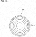
- Fig. 16 schematically illustrates a DOE lens 30.
- the DOE lens 30 includes plural circumferential diffraction grooves 31.
- the DOE lens 30 may be used as the focusing lens 27 or the collimator lens 28.
- a grating mirror may be used instead of the bend mirror 25.
- the lens 1162 in Fig. 2 can function as a focusing lens, for example. That is, the function of the focusing optical element can be realized by eccentrically rotating the lens 1162 in a direction perpendicular to the optical axis, or by moving the lens 1162 up and down or back and forth in a direction perpendicular to the optical axis in Fig. 2 .
- the focusing optical element focuses the laser beam on plural spots in a unit area within a unit time, the unit area having a radius of 0.5 mm of an optical axis of the laser beam, and the unit time being the time from when the workpiece starts to melt to when the melting of the workpiece ends.
- the beam energy per unit time is substantially uniformly applied to the unit area. As a result, even a thick sheet having a sheet thickness of 3 mm or more can be cut with high quality.
- an iron-based material (stainless steel) is used as the sheet metal W1.
- the quality of a cutting surface can be significantly improved with the laser processing machine and the laser cutting method according to the embodiment.
- a disk laser oscillator may be used instead of the fiber laser oscillator or the DDL oscillator.
- the present invention is applicable to the case where a workpiece is cut using a laser beam having a wavelength in a 1 ⁇ m band or a shorter wavelength band.
Landscapes
- Physics & Mathematics (AREA)
- Optics & Photonics (AREA)
- Engineering & Computer Science (AREA)
- Plasma & Fusion (AREA)
- Mechanical Engineering (AREA)
- Laser Beam Processing (AREA)
Applications Claiming Priority (2)
| Application Number | Priority Date | Filing Date | Title |
|---|---|---|---|
| JP2015117126A JP6025917B1 (ja) | 2015-06-10 | 2015-06-10 | レーザ切断方法 |
| PCT/JP2016/063041 WO2016199514A1 (ja) | 2015-06-10 | 2016-04-26 | レーザ加工機及びレーザ切断方法 |
Publications (3)
| Publication Number | Publication Date |
|---|---|
| EP3308896A1 true EP3308896A1 (de) | 2018-04-18 |
| EP3308896A4 EP3308896A4 (de) | 2018-10-24 |
| EP3308896B1 EP3308896B1 (de) | 2021-03-10 |
Family
ID=57326595
Family Applications (1)
| Application Number | Title | Priority Date | Filing Date |
|---|---|---|---|
| EP16807221.3A Active EP3308896B1 (de) | 2015-06-10 | 2016-04-26 | Laserbearbeitungsvorrichtung |
Country Status (5)
| Country | Link |
|---|---|
| US (1) | US10300558B2 (de) |
| EP (1) | EP3308896B1 (de) |
| JP (1) | JP6025917B1 (de) |
| CN (1) | CN107614184B (de) |
| WO (1) | WO2016199514A1 (de) |
Families Citing this family (8)
| Publication number | Priority date | Publication date | Assignee | Title |
|---|---|---|---|---|
| JP6419901B1 (ja) * | 2017-06-20 | 2018-11-07 | 株式会社アマダホールディングス | レーザ加工機 |
| EP3517241A1 (de) * | 2018-01-29 | 2019-07-31 | Bystronic Laser AG | Optische vorrichtung zum formen eines elektromagnetischen wellenstrahls und verwendung davon, strahlbehandlungsvorrichtung und verwendung davon sowie strahlbehandlungsverfahren |
| JP7270169B2 (ja) * | 2018-05-15 | 2023-05-10 | パナソニックIpマネジメント株式会社 | レーザ装置及びそれを用いたレーザ加工装置 |
| JP6638032B1 (ja) | 2018-07-31 | 2020-01-29 | 株式会社アマダホールディングス | レーザ加工機及びレーザ加工方法 |
| JP6643444B1 (ja) * | 2018-10-22 | 2020-02-12 | 株式会社アマダホールディングス | レーザ加工機、加工条件の設定方法、及びレーザ加工機の制御装置 |
| JP6800271B2 (ja) * | 2019-04-26 | 2020-12-16 | 株式会社アマダ | レーザ加工機及び加工条件設定方法 |
| US20210260702A1 (en) * | 2020-02-20 | 2021-08-26 | Laser Machining Inc. LMI AB | Method of laser processing hydrogen fuel cell plates |
| JP7257372B2 (ja) * | 2020-11-20 | 2023-04-13 | 株式会社アマダ | レーザ加工機 |
Family Cites Families (23)
| Publication number | Priority date | Publication date | Assignee | Title |
|---|---|---|---|---|
| DE4037901A1 (de) * | 1990-11-28 | 1992-06-04 | Lambda Physik Gmbh | Verfahren zum steuern der gesamtenergiemenge einer vielzahl von laserpulsen |
| JP2658809B2 (ja) * | 1992-08-27 | 1997-09-30 | 三菱電機株式会社 | レーザ加工装置 |
| AU2002316500A1 (en) * | 2001-07-02 | 2003-01-21 | Palomar Medical Technologies, Inc. | Laser device for medical/cosmetic procedures |
| DE112006001394B4 (de) * | 2005-06-01 | 2010-04-08 | Phoeton Corp., Atsugi | Laserbearbeitungsvorrichtung und Laserbearbeitungsverfahren |
| FR2897007B1 (fr) * | 2006-02-03 | 2008-04-11 | Air Liquide | Procede de coupage avec un laser a fibre avec controle des parametres du faisceau |
| DE102007037133A1 (de) | 2006-08-24 | 2008-03-13 | Nanosystec Gmbh | Verfahren und Vorrichtung zur Erzeugung einer Mehrzahl von Material-Schwächungsbereichen oder Perforierungen |
| DE102008030868A1 (de) * | 2008-06-30 | 2009-12-31 | Krones Ag | Vorrichtung zum Beschriften von Behältnissen |
| MX355677B (es) * | 2008-08-20 | 2018-04-25 | Foro Energy Inc Star | Método y sistema para hacer avanzar un pozo de perforación utilizando un láser de potencia alta. |
| FR2935916B1 (fr) * | 2008-09-12 | 2011-08-26 | Air Liquide | Procede et installation de coupage laser avec modification du facteur de qualite du faisceau laser |
| DE102008056136A1 (de) * | 2008-10-29 | 2010-05-20 | 3D-Micromac Ag | Lasermarkierverfahren, Lasermarkiervorrichtung und Optikelement |
| JP2010105037A (ja) * | 2008-10-31 | 2010-05-13 | Neturen Co Ltd | 中空接合体及びその製造方法並びに接合装置 |
| WO2010137475A1 (ja) * | 2009-05-25 | 2010-12-02 | 三菱電機株式会社 | レーザ加工装置およびレーザ加工方法 |
| FR2949618B1 (fr) * | 2009-09-01 | 2011-10-28 | Air Liquide | Tete de focalisation laser pour installation laser solide |
| JP4820910B2 (ja) * | 2010-03-29 | 2011-11-24 | 日酸Tanaka株式会社 | レーザ切断方法、レーザ切断用ノズル及びレーザ切断装置 |
| DE102010029791A1 (de) * | 2010-06-08 | 2011-12-08 | Trumpf Werkzeugmaschinen Gmbh + Co. Kg | Verfahren zur Lasermaterialbearbeitung eines Werkstücks |
| JP5435146B2 (ja) * | 2010-10-19 | 2014-03-05 | 日産自動車株式会社 | レーザ切断方法 |
| US9415465B2 (en) * | 2011-10-20 | 2016-08-16 | Nippon Steel and Sumitomo Metal Corporation | Laser processing apparatus and laser processing method |
| JP2013107124A (ja) * | 2011-11-24 | 2013-06-06 | Mitsuboshi Diamond Industrial Co Ltd | レーザ加工方法及びレーザ加工装置 |
| CN104136952B (zh) * | 2011-12-09 | 2018-05-25 | 朗美通运营有限责任公司 | 用于改变激光束的光束参数积的光学器件和方法 |
| JP5970209B2 (ja) * | 2012-03-13 | 2016-08-17 | Towa株式会社 | 積層基板の切断方法および電子部品の製造方法 |
| CN102699526A (zh) * | 2012-06-01 | 2012-10-03 | 苏州德龙激光有限公司 | 利用激光切割加工对象物的方法和装置 |
| US9690107B2 (en) * | 2013-03-15 | 2017-06-27 | Trumpf Laser Gmbh | Device for wavelength combining of laser beams |
| KR101680416B1 (ko) * | 2013-11-01 | 2016-12-12 | 주식회사 엘지화학 | 레이저를 이용한 양극 커팅 장치 |
-
2015
- 2015-06-10 JP JP2015117126A patent/JP6025917B1/ja active Active
-
2016
- 2016-04-26 WO PCT/JP2016/063041 patent/WO2016199514A1/ja active Application Filing
- 2016-04-26 US US15/578,893 patent/US10300558B2/en active Active
- 2016-04-26 CN CN201680033382.5A patent/CN107614184B/zh active Active
- 2016-04-26 EP EP16807221.3A patent/EP3308896B1/de active Active
Also Published As
| Publication number | Publication date |
|---|---|
| EP3308896B1 (de) | 2021-03-10 |
| US20180169792A1 (en) | 2018-06-21 |
| US10300558B2 (en) | 2019-05-28 |
| EP3308896A4 (de) | 2018-10-24 |
| JP2017001059A (ja) | 2017-01-05 |
| JP6025917B1 (ja) | 2016-11-16 |
| CN107614184A (zh) | 2018-01-19 |
| WO2016199514A1 (ja) | 2016-12-15 |
| CN107614184B (zh) | 2018-12-18 |
Similar Documents
| Publication | Publication Date | Title |
|---|---|---|
| EP3308896B1 (de) | Laserbearbeitungsvorrichtung | |
| EP3388186B1 (de) | Laserbearbeitungsmaschine | |
| US10118256B2 (en) | Sheet metal processing method using laser beams and direct diode laser processing device for carrying it out | |
| EP3437783B1 (de) | Laserverarbeitungsmaschine | |
| CN103155308B (zh) | 激光装置以及具备该激光装置的激光加工装置 | |
| KR102641783B1 (ko) | 재료를 레이저 가공하기 위한 장치 및 방법 | |
| WO2010123068A1 (ja) | レーザ加工装置及びレーザ加工方法 | |
| US10471537B2 (en) | Direct diode laser processing apparatus and sheet metal processing method using the same | |
| JP2016112609A (ja) | レーザ切断装置およびレーザ切断方法 | |
| JP6637916B2 (ja) | レーザ加工機 | |
| WO2016059937A1 (ja) | ダイレクトダイオードレーザ光による板金の加工方法及びこれを実行するダイレクトダイオードレーザ加工装置 | |
| JP6197084B2 (ja) | レーザ加工機 | |
| JP2016078051A (ja) | ダイレクトダイオードレーザ加工装置及びこれを用いた板金の加工方法 | |
| JP2016078043A (ja) | レーザ加工機 | |
| JP2016078049A (ja) | ダイレクトダイオードレーザ加工装置及びこれを用いた板金の加工方法 | |
| JP6035303B2 (ja) | ダイレクトダイオードレーザ加工装置及びこれを用いた金属板の加工方法 | |
| JP6937865B2 (ja) | ダイレクトダイオードレーザ加工装置及びこれを用いた板金の加工方法 | |
| JP2016153143A (ja) | ダイレクトダイオードレーザ光による板金の加工方法及びこれを実行するダイレクトダイオードレーザ加工装置 |
Legal Events
| Date | Code | Title | Description |
|---|---|---|---|
| STAA | Information on the status of an ep patent application or granted ep patent |
Free format text: STATUS: THE INTERNATIONAL PUBLICATION HAS BEEN MADE |
|
| PUAI | Public reference made under article 153(3) epc to a published international application that has entered the european phase |
Free format text: ORIGINAL CODE: 0009012 |
|
| STAA | Information on the status of an ep patent application or granted ep patent |
Free format text: STATUS: REQUEST FOR EXAMINATION WAS MADE |
|
| 17P | Request for examination filed |
Effective date: 20180109 |
|
| AK | Designated contracting states |
Kind code of ref document: A1 Designated state(s): AL AT BE BG CH CY CZ DE DK EE ES FI FR GB GR HR HU IE IS IT LI LT LU LV MC MK MT NL NO PL PT RO RS SE SI SK SM TR |
|
| AX | Request for extension of the european patent |
Extension state: BA ME |
|
| DAV | Request for validation of the european patent (deleted) | ||
| DAX | Request for extension of the european patent (deleted) | ||
| A4 | Supplementary search report drawn up and despatched |
Effective date: 20180921 |
|
| RIC1 | Information provided on ipc code assigned before grant |
Ipc: B23K 26/142 20140101ALI20180917BHEP Ipc: B23K 26/38 20140101ALI20180917BHEP Ipc: B23K 26/064 20140101ALI20180917BHEP Ipc: B23K 26/067 20060101AFI20180917BHEP Ipc: B23K 26/08 20140101ALI20180917BHEP Ipc: B23K 26/06 20140101ALI20180917BHEP |
|
| STAA | Information on the status of an ep patent application or granted ep patent |
Free format text: STATUS: EXAMINATION IS IN PROGRESS |
|
| 17Q | First examination report despatched |
Effective date: 20190726 |
|
| GRAP | Despatch of communication of intention to grant a patent |
Free format text: ORIGINAL CODE: EPIDOSNIGR1 |
|
| STAA | Information on the status of an ep patent application or granted ep patent |
Free format text: STATUS: GRANT OF PATENT IS INTENDED |
|
| INTG | Intention to grant announced |
Effective date: 20201015 |
|
| GRAS | Grant fee paid |
Free format text: ORIGINAL CODE: EPIDOSNIGR3 |
|
| STAA | Information on the status of an ep patent application or granted ep patent |
Free format text: STATUS: GRANT OF PATENT IS INTENDED |
|
| GRAA | (expected) grant |
Free format text: ORIGINAL CODE: 0009210 |
|
| STAA | Information on the status of an ep patent application or granted ep patent |
Free format text: STATUS: THE PATENT HAS BEEN GRANTED |
|
| AK | Designated contracting states |
Kind code of ref document: B1 Designated state(s): AL AT BE BG CH CY CZ DE DK EE ES FI FR GB GR HR HU IE IS IT LI LT LU LV MC MK MT NL NO PL PT RO RS SE SI SK SM TR |
|
| REG | Reference to a national code |
Ref country code: GB Ref legal event code: FG4D |
|
| REG | Reference to a national code |
Ref country code: AT Ref legal event code: REF Ref document number: 1369283 Country of ref document: AT Kind code of ref document: T Effective date: 20210315 Ref country code: CH Ref legal event code: EP |
|
| REG | Reference to a national code |
Ref country code: DE Ref legal event code: R096 Ref document number: 602016054108 Country of ref document: DE |
|
| REG | Reference to a national code |
Ref country code: IE Ref legal event code: FG4D |
|
| REG | Reference to a national code |
Ref country code: LT Ref legal event code: MG9D |
|
| PG25 | Lapsed in a contracting state [announced via postgrant information from national office to epo] |
Ref country code: LT Free format text: LAPSE BECAUSE OF FAILURE TO SUBMIT A TRANSLATION OF THE DESCRIPTION OR TO PAY THE FEE WITHIN THE PRESCRIBED TIME-LIMIT Effective date: 20210310 Ref country code: BG Free format text: LAPSE BECAUSE OF FAILURE TO SUBMIT A TRANSLATION OF THE DESCRIPTION OR TO PAY THE FEE WITHIN THE PRESCRIBED TIME-LIMIT Effective date: 20210610 Ref country code: HR Free format text: LAPSE BECAUSE OF FAILURE TO SUBMIT A TRANSLATION OF THE DESCRIPTION OR TO PAY THE FEE WITHIN THE PRESCRIBED TIME-LIMIT Effective date: 20210310 Ref country code: FI Free format text: LAPSE BECAUSE OF FAILURE TO SUBMIT A TRANSLATION OF THE DESCRIPTION OR TO PAY THE FEE WITHIN THE PRESCRIBED TIME-LIMIT Effective date: 20210310 Ref country code: GR Free format text: LAPSE BECAUSE OF FAILURE TO SUBMIT A TRANSLATION OF THE DESCRIPTION OR TO PAY THE FEE WITHIN THE PRESCRIBED TIME-LIMIT Effective date: 20210611 Ref country code: NO Free format text: LAPSE BECAUSE OF FAILURE TO SUBMIT A TRANSLATION OF THE DESCRIPTION OR TO PAY THE FEE WITHIN THE PRESCRIBED TIME-LIMIT Effective date: 20210610 |
|
| REG | Reference to a national code |
Ref country code: AT Ref legal event code: MK05 Ref document number: 1369283 Country of ref document: AT Kind code of ref document: T Effective date: 20210310 |
|
| REG | Reference to a national code |
Ref country code: NL Ref legal event code: MP Effective date: 20210310 |
|
| PG25 | Lapsed in a contracting state [announced via postgrant information from national office to epo] |
Ref country code: SE Free format text: LAPSE BECAUSE OF FAILURE TO SUBMIT A TRANSLATION OF THE DESCRIPTION OR TO PAY THE FEE WITHIN THE PRESCRIBED TIME-LIMIT Effective date: 20210310 Ref country code: LV Free format text: LAPSE BECAUSE OF FAILURE TO SUBMIT A TRANSLATION OF THE DESCRIPTION OR TO PAY THE FEE WITHIN THE PRESCRIBED TIME-LIMIT Effective date: 20210310 Ref country code: RS Free format text: LAPSE BECAUSE OF FAILURE TO SUBMIT A TRANSLATION OF THE DESCRIPTION OR TO PAY THE FEE WITHIN THE PRESCRIBED TIME-LIMIT Effective date: 20210310 |
|
| PG25 | Lapsed in a contracting state [announced via postgrant information from national office to epo] |
Ref country code: NL Free format text: LAPSE BECAUSE OF FAILURE TO SUBMIT A TRANSLATION OF THE DESCRIPTION OR TO PAY THE FEE WITHIN THE PRESCRIBED TIME-LIMIT Effective date: 20210310 |
|
| PG25 | Lapsed in a contracting state [announced via postgrant information from national office to epo] |
Ref country code: EE Free format text: LAPSE BECAUSE OF FAILURE TO SUBMIT A TRANSLATION OF THE DESCRIPTION OR TO PAY THE FEE WITHIN THE PRESCRIBED TIME-LIMIT Effective date: 20210310 Ref country code: CZ Free format text: LAPSE BECAUSE OF FAILURE TO SUBMIT A TRANSLATION OF THE DESCRIPTION OR TO PAY THE FEE WITHIN THE PRESCRIBED TIME-LIMIT Effective date: 20210310 Ref country code: SM Free format text: LAPSE BECAUSE OF FAILURE TO SUBMIT A TRANSLATION OF THE DESCRIPTION OR TO PAY THE FEE WITHIN THE PRESCRIBED TIME-LIMIT Effective date: 20210310 Ref country code: AT Free format text: LAPSE BECAUSE OF FAILURE TO SUBMIT A TRANSLATION OF THE DESCRIPTION OR TO PAY THE FEE WITHIN THE PRESCRIBED TIME-LIMIT Effective date: 20210310 |
|
| PG25 | Lapsed in a contracting state [announced via postgrant information from national office to epo] |
Ref country code: PL Free format text: LAPSE BECAUSE OF FAILURE TO SUBMIT A TRANSLATION OF THE DESCRIPTION OR TO PAY THE FEE WITHIN THE PRESCRIBED TIME-LIMIT Effective date: 20210310 Ref country code: PT Free format text: LAPSE BECAUSE OF FAILURE TO SUBMIT A TRANSLATION OF THE DESCRIPTION OR TO PAY THE FEE WITHIN THE PRESCRIBED TIME-LIMIT Effective date: 20210712 Ref country code: SK Free format text: LAPSE BECAUSE OF FAILURE TO SUBMIT A TRANSLATION OF THE DESCRIPTION OR TO PAY THE FEE WITHIN THE PRESCRIBED TIME-LIMIT Effective date: 20210310 Ref country code: RO Free format text: LAPSE BECAUSE OF FAILURE TO SUBMIT A TRANSLATION OF THE DESCRIPTION OR TO PAY THE FEE WITHIN THE PRESCRIBED TIME-LIMIT Effective date: 20210310 Ref country code: IS Free format text: LAPSE BECAUSE OF FAILURE TO SUBMIT A TRANSLATION OF THE DESCRIPTION OR TO PAY THE FEE WITHIN THE PRESCRIBED TIME-LIMIT Effective date: 20210710 |
|
| REG | Reference to a national code |
Ref country code: DE Ref legal event code: R097 Ref document number: 602016054108 Country of ref document: DE |
|
| PG25 | Lapsed in a contracting state [announced via postgrant information from national office to epo] |
Ref country code: LU Free format text: LAPSE BECAUSE OF NON-PAYMENT OF DUE FEES Effective date: 20210426 |
|
| PLBE | No opposition filed within time limit |
Free format text: ORIGINAL CODE: 0009261 |
|
| STAA | Information on the status of an ep patent application or granted ep patent |
Free format text: STATUS: NO OPPOSITION FILED WITHIN TIME LIMIT |
|
| REG | Reference to a national code |
Ref country code: BE Ref legal event code: MM Effective date: 20210430 |
|
| PG25 | Lapsed in a contracting state [announced via postgrant information from national office to epo] |
Ref country code: ES Free format text: LAPSE BECAUSE OF FAILURE TO SUBMIT A TRANSLATION OF THE DESCRIPTION OR TO PAY THE FEE WITHIN THE PRESCRIBED TIME-LIMIT Effective date: 20210310 Ref country code: MC Free format text: LAPSE BECAUSE OF FAILURE TO SUBMIT A TRANSLATION OF THE DESCRIPTION OR TO PAY THE FEE WITHIN THE PRESCRIBED TIME-LIMIT Effective date: 20210310 Ref country code: LI Free format text: LAPSE BECAUSE OF NON-PAYMENT OF DUE FEES Effective date: 20210430 Ref country code: AL Free format text: LAPSE BECAUSE OF FAILURE TO SUBMIT A TRANSLATION OF THE DESCRIPTION OR TO PAY THE FEE WITHIN THE PRESCRIBED TIME-LIMIT Effective date: 20210310 Ref country code: CH Free format text: LAPSE BECAUSE OF NON-PAYMENT OF DUE FEES Effective date: 20210430 Ref country code: DK Free format text: LAPSE BECAUSE OF FAILURE TO SUBMIT A TRANSLATION OF THE DESCRIPTION OR TO PAY THE FEE WITHIN THE PRESCRIBED TIME-LIMIT Effective date: 20210310 |
|
| 26N | No opposition filed |
Effective date: 20211213 |
|
| GBPC | Gb: european patent ceased through non-payment of renewal fee |
Effective date: 20210610 |
|
| PG25 | Lapsed in a contracting state [announced via postgrant information from national office to epo] |
Ref country code: SI Free format text: LAPSE BECAUSE OF FAILURE TO SUBMIT A TRANSLATION OF THE DESCRIPTION OR TO PAY THE FEE WITHIN THE PRESCRIBED TIME-LIMIT Effective date: 20210310 |
|
| PG25 | Lapsed in a contracting state [announced via postgrant information from national office to epo] |
Ref country code: IE Free format text: LAPSE BECAUSE OF NON-PAYMENT OF DUE FEES Effective date: 20210426 Ref country code: GB Free format text: LAPSE BECAUSE OF NON-PAYMENT OF DUE FEES Effective date: 20210610 |
|
| PG25 | Lapsed in a contracting state [announced via postgrant information from national office to epo] |
Ref country code: IS Free format text: LAPSE BECAUSE OF FAILURE TO SUBMIT A TRANSLATION OF THE DESCRIPTION OR TO PAY THE FEE WITHIN THE PRESCRIBED TIME-LIMIT Effective date: 20210710 Ref country code: FR Free format text: LAPSE BECAUSE OF NON-PAYMENT OF DUE FEES Effective date: 20210510 |
|
| PG25 | Lapsed in a contracting state [announced via postgrant information from national office to epo] |
Ref country code: BE Free format text: LAPSE BECAUSE OF NON-PAYMENT OF DUE FEES Effective date: 20210430 |
|
| P01 | Opt-out of the competence of the unified patent court (upc) registered |
Effective date: 20230428 |
|
| PG25 | Lapsed in a contracting state [announced via postgrant information from national office to epo] |
Ref country code: CY Free format text: LAPSE BECAUSE OF FAILURE TO SUBMIT A TRANSLATION OF THE DESCRIPTION OR TO PAY THE FEE WITHIN THE PRESCRIBED TIME-LIMIT Effective date: 20210310 |
|
| PG25 | Lapsed in a contracting state [announced via postgrant information from national office to epo] |
Ref country code: HU Free format text: LAPSE BECAUSE OF FAILURE TO SUBMIT A TRANSLATION OF THE DESCRIPTION OR TO PAY THE FEE WITHIN THE PRESCRIBED TIME-LIMIT; INVALID AB INITIO Effective date: 20160426 |
|
| PG25 | Lapsed in a contracting state [announced via postgrant information from national office to epo] |
Ref country code: MK Free format text: LAPSE BECAUSE OF FAILURE TO SUBMIT A TRANSLATION OF THE DESCRIPTION OR TO PAY THE FEE WITHIN THE PRESCRIBED TIME-LIMIT Effective date: 20210310 |
|
| PG25 | Lapsed in a contracting state [announced via postgrant information from national office to epo] |
Ref country code: TR Free format text: LAPSE BECAUSE OF FAILURE TO SUBMIT A TRANSLATION OF THE DESCRIPTION OR TO PAY THE FEE WITHIN THE PRESCRIBED TIME-LIMIT Effective date: 20210310 |
|
| PGFP | Annual fee paid to national office [announced via postgrant information from national office to epo] |
Ref country code: DE Payment date: 20240418 Year of fee payment: 9 |
|
| PGFP | Annual fee paid to national office [announced via postgrant information from national office to epo] |
Ref country code: IT Payment date: 20240424 Year of fee payment: 9 |