EP3306984A1 - Drahtloskommunikationssystem, steuerungsserver und steuerungsverfahren für basisstationsumschaltoperation - Google Patents
Drahtloskommunikationssystem, steuerungsserver und steuerungsverfahren für basisstationsumschaltoperation Download PDFInfo
- Publication number
- EP3306984A1 EP3306984A1 EP16803474.2A EP16803474A EP3306984A1 EP 3306984 A1 EP3306984 A1 EP 3306984A1 EP 16803474 A EP16803474 A EP 16803474A EP 3306984 A1 EP3306984 A1 EP 3306984A1
- Authority
- EP
- European Patent Office
- Prior art keywords
- base station
- handover
- zone
- wireless base
- travel
- Prior art date
- Legal status (The legal status is an assumption and is not a legal conclusion. Google has not performed a legal analysis and makes no representation as to the accuracy of the status listed.)
- Granted
Links
Images


Classifications
-
- G—PHYSICS
- G05—CONTROLLING; REGULATING
- G05D—SYSTEMS FOR CONTROLLING OR REGULATING NON-ELECTRIC VARIABLES
- G05D1/00—Control of position, course, altitude or attitude of land, water, air or space vehicles, e.g. using automatic pilots
- G05D1/02—Control of position or course in two dimensions
- G05D1/021—Control of position or course in two dimensions specially adapted to land vehicles
- G05D1/0287—Control of position or course in two dimensions specially adapted to land vehicles involving a plurality of land vehicles, e.g. fleet or convoy travelling
- G05D1/0291—Fleet control
- G05D1/0297—Fleet control by controlling means in a control room
-
- H—ELECTRICITY
- H04—ELECTRIC COMMUNICATION TECHNIQUE
- H04W—WIRELESS COMMUNICATION NETWORKS
- H04W36/00—Hand-off or reselection arrangements
- H04W36/34—Reselection control
-
- G—PHYSICS
- G05—CONTROLLING; REGULATING
- G05D—SYSTEMS FOR CONTROLLING OR REGULATING NON-ELECTRIC VARIABLES
- G05D1/00—Control of position, course, altitude or attitude of land, water, air or space vehicles, e.g. using automatic pilots
- G05D1/02—Control of position or course in two dimensions
- G05D1/021—Control of position or course in two dimensions specially adapted to land vehicles
- G05D1/0212—Control of position or course in two dimensions specially adapted to land vehicles with means for defining a desired trajectory
- G05D1/0214—Control of position or course in two dimensions specially adapted to land vehicles with means for defining a desired trajectory in accordance with safety or protection criteria, e.g. avoiding hazardous areas
-
- H—ELECTRICITY
- H04—ELECTRIC COMMUNICATION TECHNIQUE
- H04W—WIRELESS COMMUNICATION NETWORKS
- H04W16/00—Network planning, e.g. coverage or traffic planning tools; Network deployment, e.g. resource partitioning or cells structures
- H04W16/18—Network planning tools
-
- H—ELECTRICITY
- H04—ELECTRIC COMMUNICATION TECHNIQUE
- H04W—WIRELESS COMMUNICATION NETWORKS
- H04W36/00—Hand-off or reselection arrangements
- H04W36/08—Reselecting an access point
-
- H—ELECTRICITY
- H04—ELECTRIC COMMUNICATION TECHNIQUE
- H04W—WIRELESS COMMUNICATION NETWORKS
- H04W36/00—Hand-off or reselection arrangements
- H04W36/16—Performing reselection for specific purposes
-
- H—ELECTRICITY
- H04—ELECTRIC COMMUNICATION TECHNIQUE
- H04W—WIRELESS COMMUNICATION NETWORKS
- H04W36/00—Hand-off or reselection arrangements
- H04W36/24—Reselection being triggered by specific parameters
- H04W36/32—Reselection being triggered by specific parameters by location or mobility data, e.g. speed data
- H04W36/322—Reselection being triggered by specific parameters by location or mobility data, e.g. speed data by location data
-
- H—ELECTRICITY
- H04—ELECTRIC COMMUNICATION TECHNIQUE
- H04W—WIRELESS COMMUNICATION NETWORKS
- H04W4/00—Services specially adapted for wireless communication networks; Facilities therefor
- H04W4/02—Services making use of location information
-
- H—ELECTRICITY
- H04—ELECTRIC COMMUNICATION TECHNIQUE
- H04W—WIRELESS COMMUNICATION NETWORKS
- H04W4/00—Services specially adapted for wireless communication networks; Facilities therefor
- H04W4/30—Services specially adapted for particular environments, situations or purposes
- H04W4/40—Services specially adapted for particular environments, situations or purposes for vehicles, e.g. vehicle-to-pedestrians [V2P]
- H04W4/44—Services specially adapted for particular environments, situations or purposes for vehicles, e.g. vehicle-to-pedestrians [V2P] for communication between vehicles and infrastructures, e.g. vehicle-to-cloud [V2C] or vehicle-to-home [V2H]
-
- H—ELECTRICITY
- H04—ELECTRIC COMMUNICATION TECHNIQUE
- H04W—WIRELESS COMMUNICATION NETWORKS
- H04W88/00—Devices specially adapted for wireless communication networks, e.g. terminals, base stations or access point devices
- H04W88/08—Access point devices
Definitions
- This invention relates to a wireless communication system, a control server, and a base-station switching operation control method, and especially to base-station switching operation in a wireless communication system that connects a working machine in a mine and a control server together for wireless communications.
- Patent Document 1 As documents describing handover techniques, there are Patent Document 1 and Patent Document 2.
- Patent Document 1 discloses: "a mobile communication system comprises a plurality of base stations, a plurality of wireless zones covered by the base stations, and mobile stations movable in the wireless zones, and uses one of a plurality of channels to transceive voice and data between one of the base stations and one of the mobile stations, the wireless zones continue from one to the next to form an extended wireless zone, the first base station BS11 of the base stations BS11 to BS51 notifies frequency information item(s) f11 to f51 and position information item(s) of the remaining one or more base stations, and the mobile station has a GPS receiver, and includes means for receiving the frequency information and the position information of the one or more base stations notified from the first base station BS11, detecting switching locations of wireless zones based on the data of the GPS receiver and the received position information, and triggered by the detection, switching the frequency to the frequency of the succeeding base station BS12." (extracted from the Abstract)
- Patent Document 2 discloses, as an example of dedicated short range communications (DSRC) technique in highway traffic communication systems: "in a travelling support system including a plurality of wireless base station equipment, which are arranged on the side of a road, and on-board wireless communication equipment, the wireless base station equipment transmits an inquiry about a traveling state of a vehicle located within a predetermined range of a road to the on-board wireless communication equipment, and responsive to the inquiry, the on-board wireless communication equipment transmits a response including vehicle identification information and traveling state information indicating the traveling state of the vehicle to the wireless base station equipment.
- DSRC dedicated short range communications
- the wireless base station equipment Upon receipt of the response, the wireless base station equipment extracts the vehicle identification information and the traveling state information from the response, stores them in a storage device, analyzes the traveling state information stored in association with the vehicle identification information in the storage device, determines the traveling state of the vehicle, and to the on-board wireless communication equipment, transmits necessary information according to the traveling state.” (extracted from the Abstract)
- Patent Document 1 sets handover locations based on data of a GPS receiver.
- a mine includes places, to which GPS radio waves can be hardly transmitted due to terrain conditions, such as areas below cliffs and areas behind mountains.
- terrain conditions such as areas below cliffs and areas behind mountains.
- a handover location cannot be specified, the environment for wireless communications becomes unstable, leading to a potential problem that the operation of a working machine may be interrupted.
- a travel route is generated as needed corresponding to the position of a loading machine or dumping point.
- any attempt to apply the technique of Patent Document 1 or 2 to a wireless communication system in a mine leads to a circumstance that the technique cannot fully meet the environment specific to the mine.
- the present invention has as an object thereof the provision of a wireless communication technique that allows a working machine to operate more stably in a mine.
- the present invention is characterized in that in a wireless communication system including an on-board terminal equipment mounted on a working machine, which travels along a predetermined travel route in a mine, and a control server, which manages operation of the working machine, communicably connectable together via a network including a first wireless base station and a second wireless base station, the control server comprises a travel-permitted region setting unit that for the working machine, sets a region in the travel route, for which a travel permission has been given only to the working machine, as a travel-permitted region and generates permission response information including position information of the travel-permitted region, a no-handover zone setting unit that sets a travel permission requesting zone in the travel-permitted region, in which zone, the working machine makes a setting request to the control server for setting a new travel-permitted zone as a no-handover zone in which switching of a connected base station from the first wireless base station to the second wireless base station is prohibited, a switching operation control unit that generates switching operation
- the first embodiment relates to a wireless communication system including an on-board terminal equipment mounted on a working machine, which travels along a predetermined travel route in a mine, such as an excavator, a wheel loader or a sprinkler truck, and a control server, which manages operation of the working machine, communicably connectable together via a wireless communication network, in which the wireless communication system generates handover map information to be referred to upon determination of a candidate base station when the on-board terminal equipment is connected to the wireless communication network.
- the first embodiment is characterized specifically in that the handover map representing the candidate wireless base station is configured to avoid overlapping of a boundary between communication areas with a no-handover region in which switching operation of the connected base station is prohibited.
- dump truck autonomously traveling haulage vehicle
- the working machine may, however, be a manned working machine that travels according to driving operation by an operator.
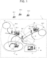
- FIG. 1 is a view illustrating the schematic configuration of the wireless communication system according to the first embodiment.
- the wireless communication system designated at reference sign 1 in FIG. 1 includes a super jumbo hydraulic excavator (hereinafter simply referred to as "excavator") 10 as a loading machine that performs digging work and loading work of rock and ore in a quarry such as a mine, dump trucks 20-1,20-2 that haul payloads such as rock, ore and/or the like, and a control server 31 installed at a control center 30 located near or remote from the quarry.
- the dump trucks 20-1,20-2 have the same configuration, the dump trucks 20-1,20-2 will hereinafter be referred to as "the dump trucks 20" when they are collectively called without distinction.
- a loading site 61 where the excavator 10 performs digging work and the excavator 10 performs loading work to the dump trucks 20, a dumping site 62 where the dump trucks 20 dump rock or ore, another dumping site 63 where a crusher (not shown) is installed and the dump trucks 20 dump ore or the like, and a haul route 60 that connects the loading site 61 and each of the dumping sites 62,63 together.
- Each dump truck 20 hauls payloads by traveling back and forth, between the loading site 61 and the dumping sites 62,63, along haul routes determined beforehand on the haul road 60.
- the excavator 10, dump trucks 20 and control server 31 are connected together for wireless communications via a wireless communication network 40.
- a wireless communication network 40 To smoothly perform these connections for wireless communications, a plurality of wireless base stations 41-1,41-2,41-3 are arranged in the mine. Via these wireless base stations, radio waves of wireless communications are transmitted and received. Radio waves attenuate as the 41-1,41-2,41-3 increase.
- Reference signs 42-1, 42-2, 42-3 in FIG. 1 indicate ranges, in which the individual wireless base stations 41-1,41-2,41-3 and each dump truck 20 can perform transmission and reception of radio waves.
- the individual wireless base stations 41-1, 41-2, 41-3 are arranged so that the ranges (hereinafter called “communication areas") 42-1, 42-2, 42-3, in which radio waves can be transmitted, overlap one to the next, whereby a connection to the wireless communication network 40 is feasible from any point insofar as the point is located on the travel route 64.
- the ranges in which radio waves can be transmitted are illustrated by round shapes in FIG. 1 . Actually, however, these ranges may not have round shapes under the influence of the terrain.
- the wireless base stations 41-1,41-2,41-3 have the same configuration, the wireless base stations 41-1,41-2,41-3 will hereinafter be referred to as "the wireless base stations 41" when they are collectively called without distinction.
- the excavator 10 and dump trucks 20 each carry a position calculating device 269 (seeFIG. 2), for example, a global positioning system (GPS) for acquiring the position of the own vehicle by receiving positioning radio waves from at least three navigation satellites 50-1,50-2,50-3.
- a position calculating device 269 for example, a global positioning system (GPS) for acquiring the position of the own vehicle by receiving positioning radio waves from at least three navigation satellites 50-1,50-2,50-3.
- GPS global positioning system
- the excavator 10 includes an antenna 18 disposed at a location of good visibility, for example, on a top part of a cab for connection with the wireless communication network 40.
- the dump trucks 20 each include an antenna 25 disposed at a location of good visibility, for example, on a front part of its top wall for connection with the wireless communication network 40. Further, the dump trucks 20 are each provided with an on-board terminal equipment 26 that communicates with the control server 31 via the wireless communication network 40 to perform autonomous travel control of the dump truck 20.
- the control server 31 is connected with an antenna 32 via a wired communication network 33 (see FIG. 2 ), is connectable with the wireless base stations 41-1,41-2,41-3 via the wireless communication network 40, and communicates with the excavator 10 and each of the dump trucks 20.
- FIG. 2 a description will be made about the hardware configurations of the control server 31 and on-board terminal equipment 26 in FIG. 1 .
- the control server 31 is configured including a server-side control device 311, a server-side input device 312, a server-side display device 313, a server-side communication device 314, a communication bus 315, a route map information storage unit 316, a communication quality information storage unit 317, a region information storage unit 318, a handover map information storage unit 319, and a no-handover region information storage unit 320.
- the server-side control device 311 controls operation of the individual elements of the control server 31, and is configured including hardware, which in turn includes a computing and control unit such as a central processing unit (CPU) and storage units such as a read only memory (ROM), a random access memory (RAM) and a hard disk drive (HDD), and software to be executed by the server-side control device 311.
- a computing and control unit such as a central processing unit (CPU) and storage units such as a read only memory (ROM), a random access memory (RAM) and a hard disk drive (HDD), and software to be executed by the server-side control device 311.
- These hardware executes software such as a handover map information generating program according to the present invention and an autonomous travel program for executing autonomous travel control of the dump trucks 20, whereby the individual functions of the control server 31 are implemented.
- the server-side input device 312 is configured of input devices such as a mouse and a keyboard, and functions as an interface that accepts input operation from an operator.
- the server-side display device 313 is configured of a liquid crystal monitor or the like, and functions as an interface that displays and provides information to the operator.
- the server-side communication device 314 is a wireless communication device.
- the communication bus 315 electrically connects the individual elements together.
- the route map information storage unit 316 is configured using a storage unit capable of fixedly storing map information, for example, a HDD.
- the map information is defined by individual points (hereinafter called “nodes”) on the travel route, and links connecting the adjacent nodes each other.
- the map information may also include terrain information of the mine, and absolute coordinates (three-dimensional real coordinates calculated based on positioning radio waves) of the individual nodes.
- identification information hereinafter called “node IDs" and “link IDs” is given to specifically identify them.
- the communication quality information storage unit 317 stores data communication quality information (hereinafter simply referred to as "communication quality information") at desired points in the mine.
- the communication quality information may be configured by accumulating those transmitted from the individual dump trucks to the control server 31, or may be communication index values (for example, radio wave intensities), which represent data communication qualities of wireless communications, collected by a mobile survey vehicle while traveling on the travel route and then stored.
- the region information storage unit 318 stores region information that includes position information of travel-permitted regions set for the individual dump trucks 20.
- the handover map information storage unit 319 stores handover map information that includes information of base stations, with which on-board terminal equipment should be connected, at desired position coordinates in the area of the mine.
- the no-handover region information storage unit 320 stores no-handover region information that defines areas, in each of which a handover is prohibited, in the area of the mine.
- the on-board terminal equipment 26 mounted on each dump truck 20 is provided with a terminal-side control device 261, a terminal-side input device 262, a terminal-side display device 263, a terminal-side communication device 264, a communication bus 265, a route map information storage unit 266, and a handover map information storage unit 270.
- Theon-board terminal equipment 26 is connected to each of a travel controller 267 mounted on the dump truck 20, a peripheral sensor device 268, and a position calculating device 269.
- the travel controller 267 is a control system, which transmits an acceleration or deceleration amount, a braking amount and a steering angle to travel drive devices relating to traveling of the dump truck 20, such as an accelerator device, a brake device and a steering device of the dump truck 20.
- the peripheral sensor device 268 is a sensor for detecting an obstacle in front of the dump truck 20 and surrounding environments, such as a millimeter-wave radar sensor or a front camera, and no limitation is imposed on its kind. A result of detection of the obstacle is outputted to the travel controller 267, and if necessary, is used for braking operation.
- the terminal-side control device 261, terminal-side input device 262, terminal-side display device 263, terminal-side communication device 264, communication bus 265, route map information storage unit 266, and handover map information storage unit 270 are of the same configurations and perform the same functions as the server-side control device 311, server-side input device 312, server-side display device 313, server-side communication device 314, and communication bus 315, respectively.
- the route map information storage unit 316 of the control server 31 and the route map information storage unit 266 of the on-board terminal equipment 26 store the same route map information.
- the handover map information storage unit 270 stores the same information as the handover map information storage unit 319 included in the control server 31.
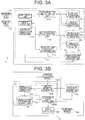
- FIGS. 3A and 3B are functional block diagrams illustrating principal functions of the control server and on-board terminal equipment in the first embodiment, in which FIG. 3A illustrates the configuration of the control server, and FIG. 3B illustrates the configuration of the on-board terminal equipment.
- the server-side control device 311 of the control server 31 is provided with a travel-permitted region setting unit 311a, a no-handover zone setting unit 311b, a handover map information generating unit 311c, a server-side communication control unit 311d, an input control unit 311e, and a display control unit 311f.
- the travel-permitted region setting unit 311a sets, for each dump truck 20, a region in the travel route, for which a travel permission has been given only to the working machine, as a travel-permitted region, and generates permission response information including position information of the travel-permitted region.
- the travel-permitted region setting unit 311a sets a front boundary point at a point forward of the current position of the dump truck 20 on the travel route 64, and sets a rear boundary point at a point rearward of the front boundary point. Further, a region in the travel route 64, which is located between the front boundary point and the rear boundary point, is set as a travel-permitted region for the dump truck 20 which transmitted setting request information for a new travel-permitted region.
- a point nearer by a permission request distance, which has been determined in view of a stoppable distance of the dump truck 20, from the front boundary point is called a "permission requesting point”
- the zone between the front boundary point and the permission requesting point is called a “permission requesting zone”.
- a braking start point is set in the permission requesting zone at a point nearer than the front boundary point as a reference and apart by the distance in which the dump truck 20 can stop without traveling beyond the front boundary point.
- the no-handover region setting unit 311b sets the permission requesting zone out of the travel-permitted region as a no-handover zone in which switching operation of the connected wireless base station is prohibited, and stores the no-handover zone in the no-handover zone information storage unit 320.
- the no-handover zone setting unit 311b also sets the inside of the loading site 61 and the insides of the dumping sites 62,63 as no-handover zones. These no handover zones are defined as closed zones in the mine.
- the handover map information generating unit 311c With reference to the communication quality information storage unit 317, the handover map information generating unit 311c generates provisional handover map information, which provisionally sets a boundary where switching operation between the first wireless base station 41-1 and the second wireless base station 41-2 is to be executed, based on the data communication quality of the communication area of the first wireless base station, for example, the wireless base station 41-1 and the data communication quality of the communication area of the second wireless base station, for example, the wireless base station 41-2, and stores the provisional handover map information in the handover map information storage unit 319.
- the handover map information generating unit 311c may generate provisional handover map information, which provisionally sets the communication area of the first wireless base station 41-1 and the communication area of the second wireless base station 41-2, based on the data communication quality of the first wireless base station 41-1 and the data communication quality of the second wireless base station 41-2, and, if the boundary between the communication area 42-1 of the first wireless base station and the communication area 42-2 of the second wireless base station and the no-handover zone overlap each other, may correct the provisional handover map information so as to place the boundary outside the no-handover zone to generate corrected handover map information, and may store the corrected handover map information in the handover map information storage unit 319.
- the handover map information generating unit 311c may perform the correction based on at least one of an index value indicating data communication quality in the no-handover zone, a result of a comparison between a distance from the travel-permitted region to the first wireless base station 41-1 and a distance from the travel-permitted region to the second wireless base station 41-2, and a result of a comparison between a size of the communication area 42-1 of the first wireless base station 41-1, the communication area 42-1 of the first wireless base station 41-1 occupying the travel-permitted region, and a size of the communication area 42-2 of the second wireless base station 41-2, the communication area 42-2 of the second wireless base station 41-2 occupying the travel-permitted region.
- the server-side communication control unit 311d perform wireless data communication control processing with the on-board terminal equipment 26.
- Examples of data which are transmitted from the control server 31 to the on-board terminal equipment 26 include the corrected handover map information and the permission response information in this embodiment.
- the on-board terminal equipment 26 performs switching operation of the connected wireless base station based on the corrected handover map information, switching operation of the connected base station can be performed outside the no-handover zone. Therefore, in this embodiment, the corrected handover map information corresponds to the switching operation control information, and the handover map information generating unit that generates the corrected handover map information corresponds to the switching operation control unit.
- the input control unit 311e accepts operation which the user has performed on the server-side input device 312.
- the control server 31 may be configured such that, if the user executes operation to change the position of a boundary section between communication areas, which are displayed on the screen of the server-side display device 313, by using the server-side input device 312, for example, the input control unit 311e accepts the operation and the handover map information generating unit reflects the operation as an amount of correction to the handover map information.
- the display control unit 311f performs the generation of an image, which is to be displayed on the server-side display device 313, and display control processing.
- the on-board terminal equipment 26 will next be described with reference to FIG. 3B .
- the terminal-side control device 261 of the on-board terminal equipment 26 is provided with a terminal-side communication control unit 261a, a request information processing unit 261b, and an autonomous travel control unit 261c.
- the terminal-side communication control unit 261a executes wireless data communication control processing with the control server 31. Examples of data which are transmitted from the on-board terminal equipment 26 to the control server 31 include the permission request information, which is for requesting a new (next) travel-permitted region, and the position information of the own vehicle. The terminal-side communication control unit 261a also executes control to receive various data wirelessly transmitted from the control server 31.
- the terminal-side communication control unit 261a Based on at least one of the provisional handover map information, the corrected handover map information, the no-handover zone information, and the information for allowing the on-board terminal equipment to execute switching operation of the connected wireless base station based on the provisional handover map information (for example, the switching command information for switching operation), the terminal-side communication control unit 261a also executes switching operation in a zone outside the permission requesting zone in the travel-permitted zone, and does not execute a handover in a no-handover zone (the permission requesting zone, the inside of the loading site, the insides of the dumping sites).
- the terminal-side communication control unit 261a also executes switching operation in a zone outside the permission requesting zone in the travel-permitted zone, and does not execute a handover in a no-handover zone (the permission requesting zone, the inside of the loading site, the insides of the dumping sites).
- the terminal-side communication control unit 261a may acquire the position information of the own vehicle from the position calculating device 269 mounted on the dump truck 20, may determine, based on the information indicating the no-handover zone and the position information of the own vehicle, whether the position of the own vehicle is included in the no-handover zone, and, if the position of the own vehicle is not included in the no-handover zone and the current connected wireless base station is not the same as the wireless base station corresponding to the communication area including the position of the own vehicle in the provisional handover map information, may execute switching operation.
- the terminal-side communication control unit 261a Upon receipt of the permission response information, the terminal-side communication control unit 261a outputs it to the autonomous travel control unit 261c.
- the request information processing unit 261b generates, to the control server 31, permission request information for requesting the setting and giving of a new travel-permitted region. If no destination has been set when each dump truck 20 begins to travel, the request information processing unit 261b also generates destination request information to request the setting of a destination. Referring to the map information in the route map information storage unit 266 and the position information of the own vehicle from the position calculating device 269, the request information processing unit 261b determines whether the own vehicle has reached a permission requesting point.
- the autonomous travel control unit 261c performs travel control on the travel controller 267 so that the dump truck 20 travels along the travel route and does not travel beyond the travel-permitted region. Because the autonomous travel control unit 261c performs the travel control so that the dump truck 20 does not travel beyond the travel-permitted region, non-receipt of the permission response information causes the dump truck 20 to stop, hinders the operation of the mine, and lowers the productivity of the mine.
- FIGS. 4A to 4C are tables showing the configurations of the communication quality information, handover map information and no-handover zone information, in which FIG. 4A shows a table configuration example of the communication quality information, FIG. 4B shows a table configuration example of the handover map information, and FIG. 4C shows a table configuration example of the no-handover zone information.
- the communication quality information designated at reference sign 400 is configured as a table that tabulates measuring coordinates 401 and access point (AP, in other words, wireless base station) qualities 402.
- the measuring coordinates 401 represent desired positions in the mine field.
- the AP qualities 402 indicate quality information of data communications (hereinafter referred to as "data communication quality information") between the respective measuring coordinates 401 and all the APs arranged in the mine field. No particular limitation is imposed on the kind of the data communication quality information insofar as they are values indicating the qualities of data communications, for example, radio wave intensities or communication error rates.
- the handover map information designated at reference sign 500 are configured of AP identification information 501 and handover zone definition information 502 associated with each other.
- the AP identification information 501 serves as information that specifically identifies the individual APs.
- the handover zone definition information 502 is position information of divided zones in the mine field, which are to be connected to the APs defined by the AP identification information 501.
- the handover zone definition information 502 is communication areas of the individual APs. When the dump truck 20 travels across adjacent communication areas, a handover is performed in a boundary section between the communication areas.
- Various forms can be contemplated as the form of the handover zone definition information 502.
- Illustrative are a set of vertex coordinates for defining line segments dividing an area, and a round area defined by information of the coordinates of a center point and a radius.
- the expression method of the handover zone definition information 502 is, therefore, not limited to the example in this embodiment .
- the no-handover zone definition information designated at reference sign 601 defines areas, in which the performance of handover processing is prohibited in the mine field, by their position information. Concerning the manner of the definition of the zone information, they may be defined in various forms like the handover zone definition information 502.
- FIGS. 5A to 5C are diagrams illustrating operation of the dump truck traveling according to the travel-permitted regions, in which FIG. 5A illustrates a state of the dump truck traveling in a travel-permitted region n, FIG. 5B illustrates a state that the dump truck has reached a permission requesting point, and FIG. 5C illustrates the state of setting of a new travel-permitted region.
- the travel route 64 is defined using nodes 65 and links 66.
- the travel-permitted region n includes seven nodes 65 and six links 66. These nodes and links are specified in the route map information.
- a rear boundary point of the travel-permitted region n is indicated by BP_n, while its front boundary point is indicated by FP_n.
- a zone from a permission requesting point RP_n, which is a point where the dump truck 20 begins to transmit setting request information to the control server for a next new travel-permitted zone, to the front boundary point FP_n is called a "permission requesting zone".
- This embodiment is characterized in that the permission requesting zone is set as a no-handover zone, in which the on-board terminal equipment 26 is prohibited to perform a handover, and a handover is specified to be performed in a zone other than the permission requesting zone on the travel route.
- the first node rearward of the front boundary point FP_n is a braking start point SP_n where braking operation is to be started.
- the dump truck 20 begins to transmit permission request information from the permission requesting point RP_n (see FIG. 5B ), and, if the dump truck 20 cannot receive permission response information indicating a next new travel-permitted region from the control server 31 when the dump truck 20 has reached the braking start point SP_n, braking operation is started.
- the braking start point SP_n is set at a point that allows the dump truck 20 to stop before the front boundary point FP_n when braking operation is started there. Therefore, the dump truck 20 can stop before traveling beyond the front boundary point FP_n and can stop without traveling beyond the travel-permitted region n. Even if a preceding vehicle exists, the dump truck 20 can hence avoid an interference with the preceding vehicle.
- the control server 31 Upon receipt of the permission request information, the control server 31 vacates the travel-permitted region n in rear of the dump truck 20. For the vacated region, a travel permission can be given to another dump truck. The control server 31 then sets a new travel-permitted region n+1.
- the new travel-permitted region n+1 has, as a front boundary point FP_n+1, a node at a greatest distance that can be set as a travel-permitted region (if there is a preceding vehicle, however, the frontmost end of a vacated region set in rear of the vehicle) .
- FP_n+1 a node at a greatest distance that can be set as a travel-permitted region (if there is a preceding vehicle, however, the frontmost end of a vacated region set in rear of the vehicle) .
- the travel-permitted region n+1 is a region from the front boundary point FP_n+1 to the rear boundary point BP_n+1, in which a permission request point RP_n+1 and a braking start point SP_n+1 are included.
- the permission requesting zone is also updated correspondingly.
- the no-handover zone is also updated. It is to be noted that this embodiment can be also applied when a travel-permitted region is set fixedly (statically) on the travel route 64.
- FIG. 6 is a flow chart illustrating the flow of the handover map information generating processing in the first embodiment.
- processing (S601 to S602) that generates provisional handover map information based on data communication quality information and setting processing (S611 to S614) of a no-handover zone are executed in parallel.
- processing (S621 to S625) that resets the boundaries of communication areas in the provisional handover map information by using no-handover zone information and finalizes the handover map information is executed.
- corrected handover map information is generated corresponding to changes in the status of data communication quality.
- the communication quality information in the communication quality information storage unit 317 is updated (S601/Yes) .
- the handover map information generating unit 311c reads the communication quality information stored in the communication quality information storage unit 317, and based on the communication quality information, generates provisional handover map information (S602) .
- the handover map information generating unit 311c may generate handover map information by connecting measuring coordinates 401, where an index value of data communication quality predetermined to lower the risk of interruptions of wireless communications by the AP qualities 402 in the communication quality table (see FIG. 4A ) is satisfied, to set a boundary at which a handover is to be performed, and defining a closed zone.
- the handover map information generated as described above sets the same AP to be a candidate base station in the closed zone. Boundaries in the handover map indicate points where switching operation of the connected base station is to be performed, that is, handover points.
- the user may operate the server-side input device 312 to manually generate the handover map information.
- step S601 If the communication quality information has not been updated in step S601 (S610/No), the processing advances to step S621.
- the travel-permitted region setting unit 311a receives permission request information from the dump truck 20 and sets a new travel-permitted region (S611/Yes), the travel-permitted region setting unit 311a computes the position of a permission requesting zone in the new travel-permitted region (S612), and stores it as zone information in the region information storage unit 318.
- the no-handover zone setting unit 311b cancels the setting of the no-handover zone set in the permission requesting zone in the vacated travel-permitted region n, and updatably sets a new permission requesting zone n+1 as a no-handover zone (S613).
- no-handover zone setting unit 311b cancels the setting of the no-handover zone in the original boundary, and updatably sets the inside of a new boundary as a no-handover zone (S615).
- step S611/No If no new travel-permitted region has been set (S611/No), the processing advances to step S614. If no change has been made to the boundary of any of the loading site and dumping sites (S614/No), the processing advances to step S621.
- the handover map information generating unit 311c determines if the communication areas of plural APs are included in each no-handover zone, in other words, if each no-handover zone and the boundary between different communication areas overlap.
- step S621/ If affirmative (S621/Yes), one of the plural communication areas included in the no-handover zones is specified, and the provisional handover map information is changed so as to make only the specified communication areas occupy the no-handover zone, whereby a corrected handover map is generated (S622) .
- a guideline for selecting the one communication area at this time there is a method such as, for example, selecting a communication area of the largest area, selecting a communication area shortest in distance to the associated AP, or selecting a communication area of better data communication quality. If negative in step S621 (S621/No), the processing advances to step S623.
- the processing returns to step S621. If has completed verification (S623/Yes), the handover map information generating unit 311c updatably stores the handover map information in the handover map information storage unit 319 (S624).
- the server-side communication control unit 311d transmits the corrected handover map information from the server-side communication device 314 to each dump truck 20 (S625) .
- the dump truck 20 which has received the corrected handover map information updates the handover information in the handover map information storage unit 270 of the on-board terminal equipment 26.
- synchronization is realized in handover map information between the control server 31 and the on-board terminal equipment 26, so that a candidate base station for the dump truck 20 is selected according to the latest handover map information.
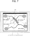
- FIG. 7 is a view illustrating an illustrative display screen showing a state that a boundary between communication areas and a no-handover zone overlap each other.
- FIG. 8 is a view illustrating another illustrative display screen showing a state that the boundary between the communication areas in FIG. 7 has been changed to outside the no-handover zone.
- the travel route 64 is divided into four communication areas, specifically AP1 area, AP2 area, AP3 area and AP4 area. From the AP3 area toward the AP2 area, a travel-permitted region 710 has been set. In the travel-permitted region 710, a zone including a front boundary point is a permission requesting zone 711, while a rear zone 712 including a rear boundary point is a zone in which a handover is allowed. The boundary between the AP1 area and the AP3 area is included in the rear zone 712, but the position of this boundary does not need any change. On the other hand, the boundary between the AP1 area and the AP2 area is included in the permission requesting zone 711, and the position of this boundary needs a change.
- each no-handover zone can take any shape insofar as it is a closed zone, and therefore no limitation is imposed on the kind of its shape. Illustrative are polygonal shapes, elliptical shapes, and the like.
- the handover map information generating unit 311c changes a boundary L1, which crosses the permission requesting zone 711, to the side of the rear zone 712 of the permission requesting zone 711 (changed from the boundary L1 to a boundary L1a).
- the handover map information generating unit 311c changes a boundary L2 in a loading site 61a to the outside of the loading site 61a (changed from the boundary L2 to a boundary L2a).
- the new handover map information so acquired is overwritten in the handover map information storage unit 270 (S902) . Subsequently, the handover map information acquired here will be referred to until new handover map information is acquired next. If the dump truck 20 has not acquired any new handover map information (S901/No), the handover map information stored in the handover map information storage unit 270 of the on-board terminal equipment 26 will be used as a reference object.
- the terminal-side communication control unit 261a acquires position information of the own vehicle from the position calculating device 269 before the permission requesting zone (S903).
- the term "permission requesting zone” as used herein means a zone in which setting request information for a new travel-permitted region is transmitted while the dump truck 20 is traveling on the travel route 64, and, if the dump truck 20 wishes to enter the loading site or one of the dumping sites, means a zone in which the dump truck 20 transmits information that requests an approach route (dynamic path) to a stop spot (loading point or dumping point) set inside the loading site or the one of the dumping sites.
- the terminal-side communication control unit 261a compares the handover map information, which is stored in the handover map information storage unit 270, with the position information of the own vehicle, and for connection to the wireless communication network 40, specifies a candidate base station (S904).
- the terminal-side communication control unit 261a performs switching operation (a handover) to the wireless base station specified in step S903 (S906) .
- the dump truck 20 continues traveling, and upon reach to a permission requesting point, transmits permission request information to the control server 31.
- the request information processing unit 261b determines, with reference to the position of the own vehicle and the contents of the permission request information, which one of a travel-permitted region and an approach route should be requested, and generates permission request information corresponding to a result of the determination.
- step S904 If the candidate base station specified in step S904 is the same as the currently-set connected base station (S905/No), the dump truck 20 does not perform any handover, and continues traveling. Subsequently, the dump truck 20 repeats the processing of from step S901 to step S906 during traveling.
- a handover is performed before the permission requesting zone, the loading site or one of the dumping sites, and no handover is performed in the permission requesting zone, the loading site or the one of the dumping sites.
- this embodiment does not require any GPS signals for determining no-handover zone, in other words, zones in which a handover can be performed so that, even under a mine environment that is prone to the occurrence of GPS electromagnetic interference, zones in which a handover is performed can be determined without being affected by such a mine environment.
- the insides of the loading site and dumping sites are set as no-handover zones with no exception, so that positional changes of the approach routes do not affect handover operations.
- a control server generates handover map information, receives from each dump truck periodically-transmitted position information of the own vehicle, and performs on the side of the control server a determination as to whether the performance of a handover by the dump truck is needed; and, if the performance of the handover is determined to be needed, the control server outputs an execution command for handover processing (switching command information) to the side of the dump truck, and upon receipt of the execution command for handover processing, the handover processing is performed on the side of the dump truck.
- switching command information switching command information
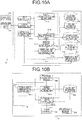
- FIG. 10A and 10B are functional block diagrams illustrating principal functions of a control server and an on-board terminal equipment in a second embodiment, in which FIG. 10A illustrates the configuration of the control server, and FIG. 10B illustrates the configuration of the on-board terminal equipment.
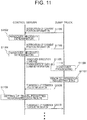
- FIG. 11 is a sequence diagram showing a flow of processing at the control server and on-board terminal equipment in the second embodiment.
- control server designated at reference sign 31 in the second embodiment also includes a handover necessity determination unit 311g in addition to the configuration of the control server 31 in the first embodiment.
- the on-board terminal equipment designated at reference sign 26 is different in that the handover map information storage unit 270 is not included.
- the handover necessity determination unit 311g determines a need for switching operation of the connected wireless base station, and generates and transmits switching command information for switching operation to the on-board terminal equipment. If the on-board terminal equipment performs switching operation of the connected wireless base station according to the switching command information, the switching operation of the connected base station can be performed outside a no-handover zone. Therefore, in this embodiment, the switching command information corresponds to the switching operation control information, and the handover map information generating unit and handover necessity determination unit, which are needed to generate the switching command information, correspond to the switching operation control unit.
- FIG. 11 a description will be made of a communication flow between the control server and the dump truck, and a processing flow. It is assumed that upon performing the processing of FIG. 11 , handover map information for the mine has already been prepared by the procedures shown in FIG. 12 .
- the dump truck 20 transmits, to the control server 31, the position information of the own vehicle, which the position calculating device 269 periodically outputs (S1101, S1103).
- the control server 31 Based on the position information of the own vehicle of the dump truck 20 as received, the control server 31 performs a handover necessity determination (S1102, S1104).
- This handover necessity determination processing is the same processing as in the steps S904 and S905 in the first embodiment. If a handover is determined to be needed as a result of the handover necessity determination, the control server 31 transmits an execution command for the handover (switching command information) to the dump truck (S1105). Upon receipt of the switching command information, the dump truck 20 performs handover processing in accordance with the switching command information (S1106).
- the dump truck 20 exists outside a no-handover zone (permission requesting zone), because the boundary between communication areas is set to be located outside the no-handover zone.
- the dump truck 20 reaches the permission requesting zone (S1107), and transmits permission request information (S1108). Responsive to the permission request information, the control server 31 sets a new travel-permitted region or approach route (S1109), and returns permission response information, which indicates the contents of the new travel-permitted region or approach route to the dump truck 20 (S1110) .
- handover map information and no-handover zone information are transmitted to an on-board terminal equipment of a dump truck, and, if the position of the own vehicle is outside the no-handover zone, the connected wireless base station is determined with reference to the handover map information or is switched if needed. Therefore, in this embodiment, the handover map information and no-handover zone information correspond to the switching operation control information, and the handover map information generating unit for generating the handover map information corresponds to the switching operation control unit.
- FIGS. 12 and 13 a description will hereinafter be made about the third embodiment.
- FIG. 12 is a functional block diagram illustrating principal functions of the control server and on-board terminal equipment in a third embodiment.
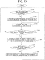
- FIG. 13 is a flow chart illustrating a flow of processing at the on-board terminal equipment in the third embodiment.
- the on-board terminal equipment 26 in the third embodiment is different from the on-board terminal equipment 26 in the first embodiment in that a no-handover zone information storage unit 271 is included.
- the terminal-side communication control unit 261a acquires the position information of the own vehicle from the position calculating device 269 (S1303) .
- the terminal-side communication control unit 261a compares the no-handover zone information, which is stored in the no-handover zone information storage unit 271, with the position information of the own vehicle. If the position of the own vehicle is not inside the no-handover zone (S1304/Yes), the processing of from step S904 to step S906 in the first embodiment is executed. If the position of the own vehicle is inside the no-handover zone (S1304/No), the processing return to step S1301 without performing handover processing.
- traveling can be continued without performing any handover in the no-handover zone.
- the above-described embodiments do not limit the present invention, and various changes and modifications can be made within a scope not departing from the spirit of the present invention.
- the above-description was made taking, as an example, the on-board terminal equipment mounted on the autonomous travel vehicle, but the present invention may also be applied to the selection of a wireless base station by an on-board terminal equipment mounted on a manned vehicle that travels according to operation by an operator.
- the control sever sets a next new travel-permitted region
- the position of a permission requesting zone may be calculated based on the distance from a front boundary point, and a determination may be made as to whether the boundary between communication areas is included in the permission-requesting zone.
- a command may be generated to execute a handover in a rear zone other than the permission requesting zone in the new travel-permitted region, and the command may be added to permission response information for responding the new travel-permitted region.
Landscapes
- Engineering & Computer Science (AREA)
- Computer Networks & Wireless Communication (AREA)
- Signal Processing (AREA)
- Aviation & Aerospace Engineering (AREA)
- Radar, Positioning & Navigation (AREA)
- Remote Sensing (AREA)
- Physics & Mathematics (AREA)
- General Physics & Mathematics (AREA)
- Automation & Control Theory (AREA)
- Mobile Radio Communication Systems (AREA)
- Traffic Control Systems (AREA)
- Control Of Position, Course, Altitude, Or Attitude Of Moving Bodies (AREA)
Applications Claiming Priority (2)
| Application Number | Priority Date | Filing Date | Title |
|---|---|---|---|
| JP2015113182A JP6539502B2 (ja) | 2015-06-03 | 2015-06-03 | 無線通信システム、管制サーバ、及び基地局切替動作制御方法 |
| PCT/JP2016/066471 WO2016195040A1 (ja) | 2015-06-03 | 2016-06-02 | 無線通信システム、管制サーバ、及び基地局切替動作制御方法 |
Publications (3)
| Publication Number | Publication Date |
|---|---|
| EP3306984A1 true EP3306984A1 (de) | 2018-04-11 |
| EP3306984A4 EP3306984A4 (de) | 2018-11-21 |
| EP3306984B1 EP3306984B1 (de) | 2020-09-02 |
Family
ID=57441395
Family Applications (1)
| Application Number | Title | Priority Date | Filing Date |
|---|---|---|---|
| EP16803474.2A Not-in-force EP3306984B1 (de) | 2015-06-03 | 2016-06-02 | Basisstationsschaltung für eine bergbauarbeitsmaschine |
Country Status (7)
| Country | Link |
|---|---|
| US (1) | US10244456B2 (de) |
| EP (1) | EP3306984B1 (de) |
| JP (1) | JP6539502B2 (de) |
| CN (1) | CN107431967B (de) |
| AU (1) | AU2016272788B2 (de) |
| CA (1) | CA2988095C (de) |
| WO (1) | WO2016195040A1 (de) |
Families Citing this family (19)
| Publication number | Priority date | Publication date | Assignee | Title |
|---|---|---|---|---|
| US10392036B2 (en) * | 2015-03-05 | 2019-08-27 | Mitsubishi Electric Corporation | Train control system, base station control device, and ground wireless base station system |
| CN106604356B (zh) | 2015-10-15 | 2020-02-14 | 华为终端有限公司 | 无线通信接入方法、装置、处理器和无线终端 |
| US10593074B1 (en) * | 2016-03-16 | 2020-03-17 | Liberty Mutual Insurance Company | Interactive user interface for displaying geographic boundaries |
| CN109313451B (zh) * | 2016-06-13 | 2022-08-26 | 深圳市大疆创新科技有限公司 | 用于可移动物体环境中的位置访问管理的技术 |
| JP6675360B2 (ja) * | 2017-09-27 | 2020-04-01 | 日立建機株式会社 | 作業機械の通信状態通知システム |
| US10798635B2 (en) * | 2018-12-03 | 2020-10-06 | At&T Intellectual Property I, L.P. | Mobile edge computing for data network traffic |
| CN113615221A (zh) * | 2019-03-25 | 2021-11-05 | 三菱电机株式会社 | 便携终端装置、通信控制系统、通信控制方法及通信控制程序 |
| JP7252320B2 (ja) | 2019-03-29 | 2023-04-04 | 本田技研工業株式会社 | 制御装置、制御方法及びプログラム |
| CN110012514B (zh) * | 2019-03-29 | 2021-04-06 | 北京锦鸿希电信息技术股份有限公司 | 列车无线通信优化方法及系统 |
| US12317769B2 (en) * | 2019-05-24 | 2025-06-03 | Nileworks Inc. | Industrial machinery system, industrial machine, control apparatus, control method for industrial machinery system, and control program for industrial machinery system |
| JP7283706B2 (ja) * | 2019-11-28 | 2023-05-30 | 村田機械株式会社 | 通信システム及び通信方法 |
| US11392707B2 (en) * | 2020-04-15 | 2022-07-19 | Capital One Services, Llc | Systems and methods for mediating permissions |
| JP7390255B2 (ja) * | 2020-05-22 | 2023-12-01 | 株式会社日立製作所 | 無線運用管理システム、及び無線運用支援方法 |
| JP7379273B2 (ja) * | 2020-06-01 | 2023-11-14 | 日立建機株式会社 | 車両制御システム |
| US20230313491A1 (en) * | 2020-09-11 | 2023-10-05 | Jdc Corporation | Construction Machine |
| CN118696567A (zh) * | 2022-02-22 | 2024-09-24 | 株式会社安川电机 | 通信系统以及通信终端 |
| JP7763136B2 (ja) * | 2022-03-28 | 2025-10-31 | 日立建機株式会社 | 車両制御システム及び車両 |
| US12483906B2 (en) | 2023-01-12 | 2025-11-25 | Qualcomm Incorporated | Signal strength mapping for steering a client |
| WO2026069521A1 (ja) * | 2024-09-26 | 2026-04-02 | 株式会社Subaru | 車両の自動運転のためのサーバ制御システム |
Family Cites Families (19)
| Publication number | Priority date | Publication date | Assignee | Title |
|---|---|---|---|---|
| SE396335B (sv) * | 1975-12-10 | 1977-09-19 | Saab Scania Ab | Anordning vid ett automatiskt fordonskontrollsystem |
| JP3424910B2 (ja) * | 1998-12-01 | 2003-07-07 | 株式会社日立製作所 | 列車の移動先地上側無線伝送装置の判定方法および移動体通信システム |
| JP4593018B2 (ja) * | 2001-06-22 | 2010-12-08 | 三菱電機株式会社 | 移動通信システム、ハンドオーバー制御方法、カーナビゲーション装置、路側機および路側機制御サーバ |
| JP2003284115A (ja) | 2002-03-27 | 2003-10-03 | Natl Inst For Land & Infrastructure Management Mlit | ハンドオーバ方式 |
| US7085571B2 (en) * | 2003-08-26 | 2006-08-01 | Kyocera Wireless Corp. | System and method for using geographical location to determine when to exit an existing wireless communications coverage network |
| JP4463757B2 (ja) * | 2005-12-09 | 2010-05-19 | 株式会社小松製作所 | 車両の走行制御装置 |
| US8294568B2 (en) * | 2006-07-10 | 2012-10-23 | Venture Corporation Limited | Wireless mine tracking, monitoring, and rescue communications system |
| JP5024108B2 (ja) | 2008-02-21 | 2012-09-12 | 富士通株式会社 | 無線基地局装置、および走行支援方法 |
| US8213388B2 (en) * | 2008-03-31 | 2012-07-03 | Cisco Technology, Inc. | Wireless hand-over in mobile deployments |
| US8428790B2 (en) * | 2009-12-22 | 2013-04-23 | Caterpillar Inc. | Systems and methods for machine control in designated areas |
| US9280902B2 (en) * | 2010-04-09 | 2016-03-08 | DSG TAG Systems, Inc. | Facilities management |
| CN102263831B (zh) * | 2011-09-06 | 2013-05-08 | 常熟理工学院 | 基于IPv6的车载网络通信系统的实现方法 |
| CN102324958A (zh) * | 2011-09-15 | 2012-01-18 | 上海大学 | 一种用于高速铁路环境下的mimo系统中的无线通信方法 |
| JP5596661B2 (ja) * | 2011-11-11 | 2014-09-24 | 株式会社小松製作所 | 鉱山機械の管理システム及び鉱山機械の管理システムの管理方法 |
| US20130268138A1 (en) * | 2012-04-05 | 2013-10-10 | Caterpillar Inc. | High Availability For Autonomous Machine Control System |
| CN103095410B (zh) * | 2013-01-09 | 2016-03-23 | 西南交通大学 | 一种轨道通信差错控制方法 |
| CN103796253B (zh) * | 2013-03-28 | 2015-04-15 | 深圳光启创新技术有限公司 | 交通工具中的终端设备与外部网络通信的系统 |
| JP5662596B1 (ja) * | 2013-08-30 | 2015-02-04 | 株式会社小松製作所 | 鉱山機械の管理システム及び鉱山機械の管理システムの管理方法 |
| DE112013000729T5 (de) * | 2013-09-11 | 2015-07-30 | Hitachi Construction Machinery Co., Ltd. | Fahrzeugverkehrs-Steuersystem |
-
2015
- 2015-06-03 JP JP2015113182A patent/JP6539502B2/ja not_active Expired - Fee Related
-
2016
- 2016-06-02 WO PCT/JP2016/066471 patent/WO2016195040A1/ja not_active Ceased
- 2016-06-02 AU AU2016272788A patent/AU2016272788B2/en not_active Ceased
- 2016-06-02 EP EP16803474.2A patent/EP3306984B1/de not_active Not-in-force
- 2016-06-02 CA CA2988095A patent/CA2988095C/en active Active
- 2016-06-02 CN CN201680021097.1A patent/CN107431967B/zh not_active Expired - Fee Related
- 2016-06-02 US US15/578,774 patent/US10244456B2/en active Active
Also Published As
| Publication number | Publication date |
|---|---|
| EP3306984A4 (de) | 2018-11-21 |
| WO2016195040A1 (ja) | 2016-12-08 |
| US20180302835A1 (en) | 2018-10-18 |
| CA2988095C (en) | 2019-11-12 |
| CN107431967B (zh) | 2020-06-23 |
| AU2016272788B2 (en) | 2019-07-18 |
| US10244456B2 (en) | 2019-03-26 |
| CA2988095A1 (en) | 2016-12-08 |
| JP2016225944A (ja) | 2016-12-28 |
| AU2016272788A1 (en) | 2017-12-21 |
| CN107431967A (zh) | 2017-12-01 |
| JP6539502B2 (ja) | 2019-07-03 |
| EP3306984B1 (de) | 2020-09-02 |
Similar Documents
| Publication | Publication Date | Title |
|---|---|---|
| EP3306984B1 (de) | Basisstationsschaltung für eine bergbauarbeitsmaschine | |
| AU2014388516B2 (en) | Vehicle driving management system and operation management server | |
| JP6564954B2 (ja) | 管制制御装置及び車載通信端末装置 | |
| AU2015385012B2 (en) | Traffic control server and system | |
| AU2015326185B2 (en) | Traffic management control device | |
| JP6247773B2 (ja) | 運転支援システム、車両、運転支援端末装置、及び運転支援プログラム | |
| JP6339412B2 (ja) | 交通管制サーバ | |
| JP2015194933A (ja) | 車両走行システム及び管制サーバ | |
| CN116547622B (zh) | 地下车辆监测系统领域 | |
| WO2016027830A1 (ja) | 管制制御装置及び運搬車両の走行シミュレーション方法 | |
| JPH09508740A (ja) | 自律走行車両システムにおける資源に対するアクセスを管理するシステム及び方法 | |
| JP6805348B2 (ja) | 車両管理装置、車両管理方法およびプログラム | |
| EP4130917B1 (de) | System zum autonomen fahren | |
| US20230324928A1 (en) | Vehicle Management System | |
| JPWO2015151291A1 (ja) | 交通管制サーバ及びシステム | |
| JP2013185940A (ja) | 情報提供装置および情報提供方法 | |
| JP2019120666A (ja) | ナビゲーション装置、ナビゲーション方法、及びナビゲーションプログラム | |
| US20250251741A1 (en) | Unmanned vehicle management system and unmanned vehicle management method | |
| JP7390977B2 (ja) | 安全管理システム、及び、安全管理方法 | |
| JP2016086305A (ja) | 無線システム及び運行管理サーバ | |
| KR102806626B1 (ko) | 자율주행 차량의 주행 가이드를 위한 사용자 인터페이스 제공방법, 장치 및 컴퓨터프로그램 | |
| JP2020051833A (ja) | 地図データのダウンロード方法及び地図記録装置 |
Legal Events
| Date | Code | Title | Description |
|---|---|---|---|
| STAA | Information on the status of an ep patent application or granted ep patent |
Free format text: STATUS: THE INTERNATIONAL PUBLICATION HAS BEEN MADE |
|
| PUAI | Public reference made under article 153(3) epc to a published international application that has entered the european phase |
Free format text: ORIGINAL CODE: 0009012 |
|
| STAA | Information on the status of an ep patent application or granted ep patent |
Free format text: STATUS: REQUEST FOR EXAMINATION WAS MADE |
|
| 17P | Request for examination filed |
Effective date: 20180103 |
|
| AK | Designated contracting states |
Kind code of ref document: A1 Designated state(s): AL AT BE BG CH CY CZ DE DK EE ES FI FR GB GR HR HU IE IS IT LI LT LU LV MC MK MT NL NO PL PT RO RS SE SI SK SM TR |
|
| AX | Request for extension of the european patent |
Extension state: BA ME |
|
| DAV | Request for validation of the european patent (deleted) | ||
| DAX | Request for extension of the european patent (deleted) | ||
| A4 | Supplementary search report drawn up and despatched |
Effective date: 20181024 |
|
| RIC1 | Information provided on ipc code assigned before grant |
Ipc: G05D 1/02 20060101ALN20181018BHEP Ipc: H04W 36/32 20090101AFI20181018BHEP |
|
| GRAP | Despatch of communication of intention to grant a patent |
Free format text: ORIGINAL CODE: EPIDOSNIGR1 |
|
| STAA | Information on the status of an ep patent application or granted ep patent |
Free format text: STATUS: GRANT OF PATENT IS INTENDED |
|
| RIC1 | Information provided on ipc code assigned before grant |
Ipc: H04W 36/32 20090101AFI20191218BHEP Ipc: G05D 1/02 20060101ALN20191218BHEP |
|
| GRAJ | Information related to disapproval of communication of intention to grant by the applicant or resumption of examination proceedings by the epo deleted |
Free format text: ORIGINAL CODE: EPIDOSDIGR1 |
|
| STAA | Information on the status of an ep patent application or granted ep patent |
Free format text: STATUS: REQUEST FOR EXAMINATION WAS MADE |
|
| GRAP | Despatch of communication of intention to grant a patent |
Free format text: ORIGINAL CODE: EPIDOSNIGR1 |
|
| INTG | Intention to grant announced |
Effective date: 20200120 |
|
| STAA | Information on the status of an ep patent application or granted ep patent |
Free format text: STATUS: GRANT OF PATENT IS INTENDED |
|
| INTC | Intention to grant announced (deleted) | ||
| RIC1 | Information provided on ipc code assigned before grant |
Ipc: H04W 36/32 20090101AFI20200204BHEP Ipc: G05D 1/02 20200101ALN20200204BHEP |
|
| INTG | Intention to grant announced |
Effective date: 20200220 |
|
| RIC1 | Information provided on ipc code assigned before grant |
Ipc: G05D 1/02 20200101ALN20200211BHEP Ipc: H04W 36/32 20090101AFI20200211BHEP |
|
| GRAJ | Information related to disapproval of communication of intention to grant by the applicant or resumption of examination proceedings by the epo deleted |
Free format text: ORIGINAL CODE: EPIDOSDIGR1 |
|
| STAA | Information on the status of an ep patent application or granted ep patent |
Free format text: STATUS: REQUEST FOR EXAMINATION WAS MADE |
|
| INTC | Intention to grant announced (deleted) | ||
| GRAP | Despatch of communication of intention to grant a patent |
Free format text: ORIGINAL CODE: EPIDOSNIGR1 |
|
| STAA | Information on the status of an ep patent application or granted ep patent |
Free format text: STATUS: GRANT OF PATENT IS INTENDED |
|
| RIC1 | Information provided on ipc code assigned before grant |
Ipc: H04W 36/32 20090101AFI20200508BHEP Ipc: G05D 1/02 20200101ALN20200508BHEP |
|
| INTG | Intention to grant announced |
Effective date: 20200605 |
|
| GRAS | Grant fee paid |
Free format text: ORIGINAL CODE: EPIDOSNIGR3 |
|
| GRAA | (expected) grant |
Free format text: ORIGINAL CODE: 0009210 |
|
| STAA | Information on the status of an ep patent application or granted ep patent |
Free format text: STATUS: THE PATENT HAS BEEN GRANTED |
|
| AK | Designated contracting states |
Kind code of ref document: B1 Designated state(s): AL AT BE BG CH CY CZ DE DK EE ES FI FR GB GR HR HU IE IS IT LI LT LU LV MC MK MT NL NO PL PT RO RS SE SI SK SM TR |
|
| REG | Reference to a national code |
Ref country code: GB Ref legal event code: FG4D |
|
| REG | Reference to a national code |
Ref country code: AT Ref legal event code: REF Ref document number: 1310276 Country of ref document: AT Kind code of ref document: T Effective date: 20200915 Ref country code: CH Ref legal event code: EP |
|
| REG | Reference to a national code |
Ref country code: DE Ref legal event code: R096 Ref document number: 602016043343 Country of ref document: DE |
|
| REG | Reference to a national code |
Ref country code: IE Ref legal event code: FG4D |
|
| REG | Reference to a national code |
Ref country code: LT Ref legal event code: MG4D |
|
| PG25 | Lapsed in a contracting state [announced via postgrant information from national office to epo] |
Ref country code: LT Free format text: LAPSE BECAUSE OF FAILURE TO SUBMIT A TRANSLATION OF THE DESCRIPTION OR TO PAY THE FEE WITHIN THE PRESCRIBED TIME-LIMIT Effective date: 20200902 Ref country code: HR Free format text: LAPSE BECAUSE OF FAILURE TO SUBMIT A TRANSLATION OF THE DESCRIPTION OR TO PAY THE FEE WITHIN THE PRESCRIBED TIME-LIMIT Effective date: 20200902 Ref country code: FI Free format text: LAPSE BECAUSE OF FAILURE TO SUBMIT A TRANSLATION OF THE DESCRIPTION OR TO PAY THE FEE WITHIN THE PRESCRIBED TIME-LIMIT Effective date: 20200902 Ref country code: NO Free format text: LAPSE BECAUSE OF FAILURE TO SUBMIT A TRANSLATION OF THE DESCRIPTION OR TO PAY THE FEE WITHIN THE PRESCRIBED TIME-LIMIT Effective date: 20201202 Ref country code: GR Free format text: LAPSE BECAUSE OF FAILURE TO SUBMIT A TRANSLATION OF THE DESCRIPTION OR TO PAY THE FEE WITHIN THE PRESCRIBED TIME-LIMIT Effective date: 20201203 Ref country code: SE Free format text: LAPSE BECAUSE OF FAILURE TO SUBMIT A TRANSLATION OF THE DESCRIPTION OR TO PAY THE FEE WITHIN THE PRESCRIBED TIME-LIMIT Effective date: 20200902 Ref country code: BG Free format text: LAPSE BECAUSE OF FAILURE TO SUBMIT A TRANSLATION OF THE DESCRIPTION OR TO PAY THE FEE WITHIN THE PRESCRIBED TIME-LIMIT Effective date: 20201202 |
|
| REG | Reference to a national code |
Ref country code: NL Ref legal event code: MP Effective date: 20200902 |
|
| REG | Reference to a national code |
Ref country code: AT Ref legal event code: MK05 Ref document number: 1310276 Country of ref document: AT Kind code of ref document: T Effective date: 20200902 |
|
| PG25 | Lapsed in a contracting state [announced via postgrant information from national office to epo] |
Ref country code: LV Free format text: LAPSE BECAUSE OF FAILURE TO SUBMIT A TRANSLATION OF THE DESCRIPTION OR TO PAY THE FEE WITHIN THE PRESCRIBED TIME-LIMIT Effective date: 20200902 Ref country code: PL Free format text: LAPSE BECAUSE OF FAILURE TO SUBMIT A TRANSLATION OF THE DESCRIPTION OR TO PAY THE FEE WITHIN THE PRESCRIBED TIME-LIMIT Effective date: 20200902 Ref country code: RS Free format text: LAPSE BECAUSE OF FAILURE TO SUBMIT A TRANSLATION OF THE DESCRIPTION OR TO PAY THE FEE WITHIN THE PRESCRIBED TIME-LIMIT Effective date: 20200902 |
|
| PG25 | Lapsed in a contracting state [announced via postgrant information from national office to epo] |
Ref country code: CZ Free format text: LAPSE BECAUSE OF FAILURE TO SUBMIT A TRANSLATION OF THE DESCRIPTION OR TO PAY THE FEE WITHIN THE PRESCRIBED TIME-LIMIT Effective date: 20200902 Ref country code: RO Free format text: LAPSE BECAUSE OF FAILURE TO SUBMIT A TRANSLATION OF THE DESCRIPTION OR TO PAY THE FEE WITHIN THE PRESCRIBED TIME-LIMIT Effective date: 20200902 Ref country code: PT Free format text: LAPSE BECAUSE OF FAILURE TO SUBMIT A TRANSLATION OF THE DESCRIPTION OR TO PAY THE FEE WITHIN THE PRESCRIBED TIME-LIMIT Effective date: 20210104 Ref country code: EE Free format text: LAPSE BECAUSE OF FAILURE TO SUBMIT A TRANSLATION OF THE DESCRIPTION OR TO PAY THE FEE WITHIN THE PRESCRIBED TIME-LIMIT Effective date: 20200902 Ref country code: SM Free format text: LAPSE BECAUSE OF FAILURE TO SUBMIT A TRANSLATION OF THE DESCRIPTION OR TO PAY THE FEE WITHIN THE PRESCRIBED TIME-LIMIT Effective date: 20200902 |
|
| PG25 | Lapsed in a contracting state [announced via postgrant information from national office to epo] |
Ref country code: AL Free format text: LAPSE BECAUSE OF FAILURE TO SUBMIT A TRANSLATION OF THE DESCRIPTION OR TO PAY THE FEE WITHIN THE PRESCRIBED TIME-LIMIT Effective date: 20200902 Ref country code: AT Free format text: LAPSE BECAUSE OF FAILURE TO SUBMIT A TRANSLATION OF THE DESCRIPTION OR TO PAY THE FEE WITHIN THE PRESCRIBED TIME-LIMIT Effective date: 20200902 Ref country code: ES Free format text: LAPSE BECAUSE OF FAILURE TO SUBMIT A TRANSLATION OF THE DESCRIPTION OR TO PAY THE FEE WITHIN THE PRESCRIBED TIME-LIMIT Effective date: 20200902 Ref country code: IS Free format text: LAPSE BECAUSE OF FAILURE TO SUBMIT A TRANSLATION OF THE DESCRIPTION OR TO PAY THE FEE WITHIN THE PRESCRIBED TIME-LIMIT Effective date: 20210102 |
|
| REG | Reference to a national code |
Ref country code: DE Ref legal event code: R097 Ref document number: 602016043343 Country of ref document: DE |
|
| PG25 | Lapsed in a contracting state [announced via postgrant information from national office to epo] |
Ref country code: SK Free format text: LAPSE BECAUSE OF FAILURE TO SUBMIT A TRANSLATION OF THE DESCRIPTION OR TO PAY THE FEE WITHIN THE PRESCRIBED TIME-LIMIT Effective date: 20200902 |
|
| PLBE | No opposition filed within time limit |
Free format text: ORIGINAL CODE: 0009261 |
|
| STAA | Information on the status of an ep patent application or granted ep patent |
Free format text: STATUS: NO OPPOSITION FILED WITHIN TIME LIMIT |
|
| 26N | No opposition filed |
Effective date: 20210603 |
|
| PG25 | Lapsed in a contracting state [announced via postgrant information from national office to epo] |
Ref country code: SI Free format text: LAPSE BECAUSE OF FAILURE TO SUBMIT A TRANSLATION OF THE DESCRIPTION OR TO PAY THE FEE WITHIN THE PRESCRIBED TIME-LIMIT Effective date: 20200902 Ref country code: DK Free format text: LAPSE BECAUSE OF FAILURE TO SUBMIT A TRANSLATION OF THE DESCRIPTION OR TO PAY THE FEE WITHIN THE PRESCRIBED TIME-LIMIT Effective date: 20200902 |
|
| PG25 | Lapsed in a contracting state [announced via postgrant information from national office to epo] |
Ref country code: IT Free format text: LAPSE BECAUSE OF FAILURE TO SUBMIT A TRANSLATION OF THE DESCRIPTION OR TO PAY THE FEE WITHIN THE PRESCRIBED TIME-LIMIT Effective date: 20200902 |
|
| PG25 | Lapsed in a contracting state [announced via postgrant information from national office to epo] |
Ref country code: MC Free format text: LAPSE BECAUSE OF FAILURE TO SUBMIT A TRANSLATION OF THE DESCRIPTION OR TO PAY THE FEE WITHIN THE PRESCRIBED TIME-LIMIT Effective date: 20200902 |
|
| REG | Reference to a national code |
Ref country code: CH Ref legal event code: PL |
|
| GBPC | Gb: european patent ceased through non-payment of renewal fee |
Effective date: 20210602 |
|
| REG | Reference to a national code |
Ref country code: BE Ref legal event code: MM Effective date: 20210630 |
|
| PG25 | Lapsed in a contracting state [announced via postgrant information from national office to epo] |
Ref country code: LU Free format text: LAPSE BECAUSE OF NON-PAYMENT OF DUE FEES Effective date: 20210602 |
|
| PG25 | Lapsed in a contracting state [announced via postgrant information from national office to epo] |
Ref country code: LI Free format text: LAPSE BECAUSE OF NON-PAYMENT OF DUE FEES Effective date: 20210630 Ref country code: IE Free format text: LAPSE BECAUSE OF NON-PAYMENT OF DUE FEES Effective date: 20210602 Ref country code: GB Free format text: LAPSE BECAUSE OF NON-PAYMENT OF DUE FEES Effective date: 20210602 Ref country code: CH Free format text: LAPSE BECAUSE OF NON-PAYMENT OF DUE FEES Effective date: 20210630 |
|
| PG25 | Lapsed in a contracting state [announced via postgrant information from national office to epo] |
Ref country code: FR Free format text: LAPSE BECAUSE OF NON-PAYMENT OF DUE FEES Effective date: 20210630 |
|
| PG25 | Lapsed in a contracting state [announced via postgrant information from national office to epo] |
Ref country code: BE Free format text: LAPSE BECAUSE OF NON-PAYMENT OF DUE FEES Effective date: 20210630 |
|
| PG25 | Lapsed in a contracting state [announced via postgrant information from national office to epo] |
Ref country code: NL Free format text: LAPSE BECAUSE OF NON-PAYMENT OF DUE FEES Effective date: 20200923 Ref country code: CY Free format text: LAPSE BECAUSE OF FAILURE TO SUBMIT A TRANSLATION OF THE DESCRIPTION OR TO PAY THE FEE WITHIN THE PRESCRIBED TIME-LIMIT Effective date: 20200902 |
|
| PG25 | Lapsed in a contracting state [announced via postgrant information from national office to epo] |
Ref country code: HU Free format text: LAPSE BECAUSE OF FAILURE TO SUBMIT A TRANSLATION OF THE DESCRIPTION OR TO PAY THE FEE WITHIN THE PRESCRIBED TIME-LIMIT; INVALID AB INITIO Effective date: 20160602 |
|
| PGFP | Annual fee paid to national office [announced via postgrant information from national office to epo] |
Ref country code: DE Payment date: 20230502 Year of fee payment: 8 |
|
| PG25 | Lapsed in a contracting state [announced via postgrant information from national office to epo] |
Ref country code: MK Free format text: LAPSE BECAUSE OF FAILURE TO SUBMIT A TRANSLATION OF THE DESCRIPTION OR TO PAY THE FEE WITHIN THE PRESCRIBED TIME-LIMIT Effective date: 20200902 |
|
| PG25 | Lapsed in a contracting state [announced via postgrant information from national office to epo] |
Ref country code: MT Free format text: LAPSE BECAUSE OF FAILURE TO SUBMIT A TRANSLATION OF THE DESCRIPTION OR TO PAY THE FEE WITHIN THE PRESCRIBED TIME-LIMIT Effective date: 20200902 |
|
| REG | Reference to a national code |
Ref country code: DE Ref legal event code: R119 Ref document number: 602016043343 Country of ref document: DE |
|
| PG25 | Lapsed in a contracting state [announced via postgrant information from national office to epo] |
Ref country code: DE Free format text: LAPSE BECAUSE OF NON-PAYMENT OF DUE FEES Effective date: 20250101 |
|
| PG25 | Lapsed in a contracting state [announced via postgrant information from national office to epo] |
Ref country code: TR Free format text: LAPSE BECAUSE OF FAILURE TO SUBMIT A TRANSLATION OF THE DESCRIPTION OR TO PAY THE FEE WITHIN THE PRESCRIBED TIME-LIMIT Effective date: 20200902 |