EP3301002A1 - Sattelfahrzeug mit brennstoffzelle - Google Patents
Sattelfahrzeug mit brennstoffzelle Download PDFInfo
- Publication number
- EP3301002A1 EP3301002A1 EP17192440.0A EP17192440A EP3301002A1 EP 3301002 A1 EP3301002 A1 EP 3301002A1 EP 17192440 A EP17192440 A EP 17192440A EP 3301002 A1 EP3301002 A1 EP 3301002A1
- Authority
- EP
- European Patent Office
- Prior art keywords
- fuel cell
- unit
- frame
- cell unit
- vehicle body
- Prior art date
- Legal status (The legal status is an assumption and is not a legal conclusion. Google has not performed a legal analysis and makes no representation as to the accuracy of the status listed.)
- Granted
Links
- 239000000446 fuel Substances 0.000 title claims abstract description 88
- 239000002828 fuel tank Substances 0.000 claims abstract description 27
- 230000001681 protective effect Effects 0.000 claims description 6
- 239000001257 hydrogen Substances 0.000 description 12
- 229910052739 hydrogen Inorganic materials 0.000 description 12
- UFHFLCQGNIYNRP-UHFFFAOYSA-N Hydrogen Chemical compound [H][H] UFHFLCQGNIYNRP-UHFFFAOYSA-N 0.000 description 8
- 230000005484 gravity Effects 0.000 description 6
- 239000003570 air Substances 0.000 description 5
- 150000002431 hydrogen Chemical class 0.000 description 4
- QVGXLLKOCUKJST-UHFFFAOYSA-N atomic oxygen Chemical compound [O] QVGXLLKOCUKJST-UHFFFAOYSA-N 0.000 description 3
- 239000001301 oxygen Substances 0.000 description 3
- 229910052760 oxygen Inorganic materials 0.000 description 3
- 239000012080 ambient air Substances 0.000 description 2
- 238000006243 chemical reaction Methods 0.000 description 2
- 230000001276 controlling effect Effects 0.000 description 2
- 239000000463 material Substances 0.000 description 2
- 238000001816 cooling Methods 0.000 description 1
- 239000007789 gas Substances 0.000 description 1
- 239000007769 metal material Substances 0.000 description 1
- 230000001105 regulatory effect Effects 0.000 description 1
- 239000011347 resin Substances 0.000 description 1
- 229920005989 resin Polymers 0.000 description 1
Images


Classifications
-
- B—PERFORMING OPERATIONS; TRANSPORTING
- B62—LAND VEHICLES FOR TRAVELLING OTHERWISE THAN ON RAILS
- B62K—CYCLES; CYCLE FRAMES; CYCLE STEERING DEVICES; RIDER-OPERATED TERMINAL CONTROLS SPECIALLY ADAPTED FOR CYCLES; CYCLE AXLE SUSPENSIONS; CYCLE SIDE-CARS, FORECARS, OR THE LIKE
- B62K11/00—Motorcycles, engine-assisted cycles or motor scooters with one or two wheels
-
- B—PERFORMING OPERATIONS; TRANSPORTING
- B60—VEHICLES IN GENERAL
- B60L—PROPULSION OF ELECTRICALLY-PROPELLED VEHICLES; SUPPLYING ELECTRIC POWER FOR AUXILIARY EQUIPMENT OF ELECTRICALLY-PROPELLED VEHICLES; ELECTRODYNAMIC BRAKE SYSTEMS FOR VEHICLES IN GENERAL; MAGNETIC SUSPENSION OR LEVITATION FOR VEHICLES; MONITORING OPERATING VARIABLES OF ELECTRICALLY-PROPELLED VEHICLES; ELECTRIC SAFETY DEVICES FOR ELECTRICALLY-PROPELLED VEHICLES
- B60L50/00—Electric propulsion with power supplied within the vehicle
- B60L50/50—Electric propulsion with power supplied within the vehicle using propulsion power supplied by batteries or fuel cells
- B60L50/70—Electric propulsion with power supplied within the vehicle using propulsion power supplied by batteries or fuel cells using power supplied by fuel cells
- B60L50/71—Arrangement of fuel cells within vehicles specially adapted for electric vehicles
-
- B—PERFORMING OPERATIONS; TRANSPORTING
- B60—VEHICLES IN GENERAL
- B60L—PROPULSION OF ELECTRICALLY-PROPELLED VEHICLES; SUPPLYING ELECTRIC POWER FOR AUXILIARY EQUIPMENT OF ELECTRICALLY-PROPELLED VEHICLES; ELECTRODYNAMIC BRAKE SYSTEMS FOR VEHICLES IN GENERAL; MAGNETIC SUSPENSION OR LEVITATION FOR VEHICLES; MONITORING OPERATING VARIABLES OF ELECTRICALLY-PROPELLED VEHICLES; ELECTRIC SAFETY DEVICES FOR ELECTRICALLY-PROPELLED VEHICLES
- B60L58/00—Methods or circuit arrangements for monitoring or controlling batteries or fuel cells, specially adapted for electric vehicles
- B60L58/40—Methods or circuit arrangements for monitoring or controlling batteries or fuel cells, specially adapted for electric vehicles for controlling a combination of batteries and fuel cells
-
- B—PERFORMING OPERATIONS; TRANSPORTING
- B60—VEHICLES IN GENERAL
- B60R—VEHICLES, VEHICLE FITTINGS, OR VEHICLE PARTS, NOT OTHERWISE PROVIDED FOR
- B60R16/00—Electric or fluid circuits specially adapted for vehicles and not otherwise provided for; Arrangement of elements of electric or fluid circuits specially adapted for vehicles and not otherwise provided for
- B60R16/02—Electric or fluid circuits specially adapted for vehicles and not otherwise provided for; Arrangement of elements of electric or fluid circuits specially adapted for vehicles and not otherwise provided for electric constitutive elements
- B60R16/04—Arrangement of batteries
-
- B—PERFORMING OPERATIONS; TRANSPORTING
- B62—LAND VEHICLES FOR TRAVELLING OTHERWISE THAN ON RAILS
- B62J—CYCLE SADDLES OR SEATS; AUXILIARY DEVICES OR ACCESSORIES SPECIALLY ADAPTED TO CYCLES AND NOT OTHERWISE PROVIDED FOR, e.g. ARTICLE CARRIERS OR CYCLE PROTECTORS
- B62J43/00—Arrangements of batteries
-
- B—PERFORMING OPERATIONS; TRANSPORTING
- B62—LAND VEHICLES FOR TRAVELLING OTHERWISE THAN ON RAILS
- B62K—CYCLES; CYCLE FRAMES; CYCLE STEERING DEVICES; RIDER-OPERATED TERMINAL CONTROLS SPECIALLY ADAPTED FOR CYCLES; CYCLE AXLE SUSPENSIONS; CYCLE SIDE-CARS, FORECARS, OR THE LIKE
- B62K11/00—Motorcycles, engine-assisted cycles or motor scooters with one or two wheels
- B62K11/02—Frames
- B62K11/04—Frames characterised by the engine being between front and rear wheels
-
- B—PERFORMING OPERATIONS; TRANSPORTING
- B62—LAND VEHICLES FOR TRAVELLING OTHERWISE THAN ON RAILS
- B62M—RIDER PROPULSION OF WHEELED VEHICLES OR SLEDGES; POWERED PROPULSION OF SLEDGES OR SINGLE-TRACK CYCLES; TRANSMISSIONS SPECIALLY ADAPTED FOR SUCH VEHICLES
- B62M7/00—Motorcycles characterised by position of motor or engine
-
- B—PERFORMING OPERATIONS; TRANSPORTING
- B62—LAND VEHICLES FOR TRAVELLING OTHERWISE THAN ON RAILS
- B62J—CYCLE SADDLES OR SEATS; AUXILIARY DEVICES OR ACCESSORIES SPECIALLY ADAPTED TO CYCLES AND NOT OTHERWISE PROVIDED FOR, e.g. ARTICLE CARRIERS OR CYCLE PROTECTORS
- B62J35/00—Fuel tanks specially adapted for motorcycles or engine-assisted cycles; Arrangements thereof
-
- B—PERFORMING OPERATIONS; TRANSPORTING
- B62—LAND VEHICLES FOR TRAVELLING OTHERWISE THAN ON RAILS
- B62K—CYCLES; CYCLE FRAMES; CYCLE STEERING DEVICES; RIDER-OPERATED TERMINAL CONTROLS SPECIALLY ADAPTED FOR CYCLES; CYCLE AXLE SUSPENSIONS; CYCLE SIDE-CARS, FORECARS, OR THE LIKE
- B62K2202/00—Motorised scooters
-
- B—PERFORMING OPERATIONS; TRANSPORTING
- B62—LAND VEHICLES FOR TRAVELLING OTHERWISE THAN ON RAILS
- B62K—CYCLES; CYCLE FRAMES; CYCLE STEERING DEVICES; RIDER-OPERATED TERMINAL CONTROLS SPECIALLY ADAPTED FOR CYCLES; CYCLE AXLE SUSPENSIONS; CYCLE SIDE-CARS, FORECARS, OR THE LIKE
- B62K2204/00—Adaptations for driving cycles by electric motor
-
- Y—GENERAL TAGGING OF NEW TECHNOLOGICAL DEVELOPMENTS; GENERAL TAGGING OF CROSS-SECTIONAL TECHNOLOGIES SPANNING OVER SEVERAL SECTIONS OF THE IPC; TECHNICAL SUBJECTS COVERED BY FORMER USPC CROSS-REFERENCE ART COLLECTIONS [XRACs] AND DIGESTS
- Y02—TECHNOLOGIES OR APPLICATIONS FOR MITIGATION OR ADAPTATION AGAINST CLIMATE CHANGE
- Y02T—CLIMATE CHANGE MITIGATION TECHNOLOGIES RELATED TO TRANSPORTATION
- Y02T10/00—Road transport of goods or passengers
- Y02T10/60—Other road transportation technologies with climate change mitigation effect
- Y02T10/70—Energy storage systems for electromobility, e.g. batteries
-
- Y—GENERAL TAGGING OF NEW TECHNOLOGICAL DEVELOPMENTS; GENERAL TAGGING OF CROSS-SECTIONAL TECHNOLOGIES SPANNING OVER SEVERAL SECTIONS OF THE IPC; TECHNICAL SUBJECTS COVERED BY FORMER USPC CROSS-REFERENCE ART COLLECTIONS [XRACs] AND DIGESTS
- Y02—TECHNOLOGIES OR APPLICATIONS FOR MITIGATION OR ADAPTATION AGAINST CLIMATE CHANGE
- Y02T—CLIMATE CHANGE MITIGATION TECHNOLOGIES RELATED TO TRANSPORTATION
- Y02T90/00—Enabling technologies or technologies with a potential or indirect contribution to GHG emissions mitigation
- Y02T90/40—Application of hydrogen technology to transportation, e.g. using fuel cells
Definitions
- the present invention relates to a saddle-ride type vehicle that is provided with a fuel cell.
- a saddle-ride type vehicle has a fuel cell that generates electric power based on a chemical reaction between hydrogen and oxygen from the atmosphere.
- the fuel cell is disposed above a fuel tank that is placed in a space surrounded by a main frame and a down frame. Electrical components such as a secondary cell and an inverter are mounted in place below the down frame.
- the fuel cell is heavier than the fuel tank. Therefore, the fuel cell that is disposed above the fuel tank causes the saddle-ride type vehicle to have a center of gravity in a high position, tending to impair the stability with which the saddle-ride type vehicle travels and the stability with which the saddle-ride type vehicle is maneuvered.
- the present invention has been achieved in view of the above-mentioned circumstances, and it is an object thereof to provide a saddle-ride type vehicle which is able to travel with increased stability though it incorporates a fuel cell therein.
- a saddle-ride type vehicle comprising: a vehicle body frame; a rear wheel unit swingably supported on the vehicle body frame; a fuel cell unit supported on the vehicle body frame; a fuel tank extending rearwardly from the fuel cell unit over the rear wheel unit; and a secondary cell that is charged with electric power from the fuel cell unit and disposed below the fuel cell unit and the fuel tank.
- the fuel tank, which stores hydrogen, and the fuel cell unit, which is supplied with hydrogen are thus juxtaposed in the longitudinal directions of the saddle-ride type vehicle, and the secondary cell is disposed below the fuel cell unit. Therefore, the center of gravity of the saddle-ride type vehicle can be made lower than if the fuel tank, the fuel cell unit, and the secondary cell are superposed in an up-down direction.
- the center of gravity of the saddle-ride type vehicle is positioned as forwardly of the rear wheel unit as possible, allowing the saddle-ride type vehicle to travel with increased stability.
- the saddle-ride type vehicle further comprising a protective member for the fuel cell unit, interposed between the fuel cell unit and the secondary cell.
- the secondary cell and hydrogen can be prevented from contacting each other, and the use of the protective member contributes to a reduction in the number of parts used.
- the saddle-ride type vehicle further comprising an electric motor for driving a rear wheel; and a controller for controlling electric power supplied to the electric motor generating a drive force for the rear wheel, the controller being disposed below the fuel cell unit and the fuel tank and behind the secondary cell.
- the controller and hydrogen can be prevented from contacting each other.
- required wiring can be short as the controller is disposed below the fuel cell unit and behind the secondary cell.
- the controller and the secondary cell are fixed to an electrical component cover mounted on the vehicle body frame.
- controller and the secondary cell are assembled on the vehicle body cover and thereafter the vehicle body cover is installed together with the fuel cell unit on the vehicle body frame, they can be installed in position with ease and with increased accuracy.
- the saddle-ride type vehicle further comprising a frame unit mounted on the vehicle body frame and supporting the electrical component cover; wherein the electrical component cover is defined along the frame unit and has positioning portions on an outer surface thereof, the positioning portions positioning the frame unit.
- the frame unit is disposed on the outer surface of the electrical component cover, the rigidity of the electrical component cover can be increased. Since the positioning portions are provided on the outer surface of the electrical component cover, the assemblability of the electrical component cover with respect to the frame unit and the vehicle body frame can be improved.
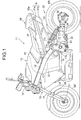
- a saddle-ride type vehicle or two-wheeled motor vehicle 11 includes a vehicle body frame 12 and a vehicle body cover 13 mounted on the vehicle body frame 12.
- the vehicle body frame 12 includes a head pipe 15 on which a front fork 14 is steerably supported, a pair of left and right main frames 16 extending rearwardly and downwardly from the head pipe 15 at a first angle with respect to a horizontal plane, a pair of left and right pivot frames 17 joined to the respective rear ends of the main frames 16 at a first junction 17a and extending downwardly from the rear ends of the main frames 16, a pair of left and right down frames 18 extending downwardly from the head pipe 15 at a second angle, which is larger than the first angle, with respect to the horizontal plane, and a pair of left and right lower frames 19 extending from the respective rear ends of the down frames 18 and joined to the respective pivot frames 17 at a second junction 17b that is lower than the first junction 17a.
- a front wheel WF is rotat
- the two-wheeled motor vehicle 11 includes a rear wheel unit 22.
- the rear wheel unit 22 has a swing frame 24 coupled to the pivot frames 17 via a horizontally extending pivot 23, and an electric motor 25 combined with the swing frame 24 and generating a drive force based on electric power supplied thereto.
- a rear wheel WR is rotatably supported on a free end of the swing frame 24 around an axle 26 parallel to the pivot 23. The rear wheel WR is thus coupled to the vehicle body frame 12.
- the lower frames 19 are disposed forwardly of the rear wheel WR.
- the electric motor 25 has a drive shaft connected to the rear wheel WR so as to transmit the drive force to the rear wheel WR.
- a rear cushion 27 is installed between the vehicle body frame 12 and the swing frame 24.
- the rear cushion 27 has one end coupled to the pivot frames 17 at a third junction 17c that is provided above the pivot 23.
- the rear cushion 27 limits swinging movement of the vehicle body frame 12 with respect to the rear wheel unit 22, thereby minimizing vibrations transmitted from the rear wheel WR to the vehicle body frame 12.
- the two-wheeled motor vehicle 11 includes a fuel supply assembly 28.
- the fuel supply assembly 28 has a seat frame 31 extending rearwardly from the main frames 16 above the rear wheel WR and supporting a rider's seat 29 thereon.
- the seat frame 31 is of a monocoque structure shaped as an exhaust duct for guiding an exhaust gas from a fuel cell unit 36 (see FIG. 2 ) as far as behind the rider's seat 29.
- the fuel supply assembly 28 is coupled to the main frames 16 above the pivot frames 17.
- the seat frame 31 includes an upper body 31a and a lower body 31b that are joined to each other along a joint plane 31c which extends from the main frames 16 to the rear end of the seat frame 31.
- the rider's seat 29 is mounted on the upper body 31a. An occupant of the two-wheeled motor vehicle 11 sits astride the rider's seat 29.
- the vehicle body cover 13 includes an upper cover 32 disposed above the left and right main frames 16 and coupled to them so as to straddle them from above, a pair of left and right side covers 33 disposed beneath the left and right main frames 16 and coupled respectively thereto, an air guide plate 34 joined to the side covers 33 and extending forwardly from its rear end, and a rear cover 35 covering the seat frame 31 behind the rider's seat 29.
- the rear cover 35 defines an exhaust port 35a at the rear end of the seat frame 31.
- the fuel cell unit 36 is mounted on the vehicle body frame 12.
- the fuel cell unit 36 is supported from below on the left and right lower frames 19 behind the head pipe 15.
- the down frames 18 extend downwardly in front of the fuel cell unit 36.
- the fuel cell unit 36 has an ambient air inlet port 38 along an imaginary plane 37 perpendicular to the ground and extending in a left-right direction of the two-wheeled motor vehicle 11.
- the fuel cell unit 36 generates electric power based on a chemical reaction between hydrogen and oxygen from the atmosphere.
- the fuel cell unit 36 uses the atmosphere flowing from the ambient air inlet port 38 thereinto for supplying oxygen and cooling itself.
- the vehicle body cover 13 includes, in addition to the upper cover 32, the side covers 33, the air guide plate 34, and the rear cover 35, a fuel cell cover 39 covered with the side covers 33 and the air guide plate 34, and an electrical component cover 41 supported below the lower frames 19.
- the fuel cell cover 39 and the electrical component cover 41 are coupled to the vehicle body frame 12.
- the fuel cell cover 39 functions as a protective member for the fuel cell unit 36. Details of the electrical component cover 41 will be described below.
- the vehicle body cover 13 is formed from a molded body of resin material.
- the fuel cell cover 39 has a front wall 39a, a pair of left and right side walls 39b, and a bottom plate 39c.
- the front wall 39a is provided between the left and right down frames 18.
- the side walls 39b are provided between the left and right main frames 16 and the corresponding down frames 18 and lower frames 19.
- the side walls 39b extend in a rearward direction of the two-wheeled motor vehicle 11 from respective left and right sides of the front wall 39a.
- the bottom plate 39c is provided along the horizontal plane between the left and right lower frames 19, and connected to the lower end of the front wall 39a and the lower ends of the side walls 39b.
- Front, side and lower surfaces of the fuel cell unit 36 below the main frames 16 are covered with the fuel cell cover 39.
- the side walls 39b have left and right air inlet ports 42 defined therein. Traveling wind is introduced from the air inlet ports 42 into the fuel cell cover 39.
- the bottom plate 39c supports the fuel cell unit 36 thereon from below.
- a fuel tank 43 in the shape of a cylinder is mounted on the vehicle body frame 12.
- the fuel tank 43 is connected to a rear surface of the fuel cell unit 36, and extends rearwardly over the rear wheel unit 22.
- the fuel cell unit 36 and the fuel tank 43 are connected to each other by a fuel channel via a pressure regulating valve 44.
- the fuel tank 43 stores therein high-pressure hydrogen.
- the lower body 31b of the seat frame 31 supports the fuel tank 43 thereon from below.
- the fuel tank 43 is housed in the seat frame 31.
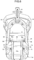
- the electrical component cover 41 is suspended and supported by the vehicle body frame 12 below the lower frames 19.
- a frame unit 45 is mounted on the electrical component cover 41.
- the frame unit 45 is disposed below the lower frames 19 and coupled to the vehicle body frame 12.
- the frame unit 45 includes a first crossbar 46 extending horizontally in the left-right direction of the two-wheeled motor vehicle 11 and joined to the left and right down frames 18, a second crossbar 48 extending horizontally in the left-right direction of the two-wheeled motor vehicle 11 and joined to brackets 47 fixed to the pivot frames 17, and a pair of left and right support frames 49 extending from the first crossbar 46 to the second crossbar 48 parallel to each other in a longitudinal direction of the two-wheeled motor vehicle 11.
- Each of the support frames 49 is made up of a first frame body 49a extending downwardly from the first crossbar 46, a second frame body 49b extending continuously from the lower end of the first frame body 49a horizontally rearwardly, and a third frame body 49c extending upwardly from the rear end of the second frame body 49b and joined to the second crossbar 48.
- the first frame body 49a, the second frame body 49b, and the third frame body 49c are constructed as a continuous single member.
- the support frames 49 each have a shape following the outer surface of the electrical component cover 41.
- the electrical component cover 41 houses therein two voltage control units 51 electrically connected to the fuel cell unit 36 via a harness (not depicted), a secondary cell 52 electrically connected to the voltage control units 51 via a harness (not depicted), an inverter (controller) 53 electrically connected to the voltage control units 51 and the secondary cell 52 via a harness (not depicted), and other electrical components.
- the direct-current (DC) voltage of the fuel cell unit 36 is dropped by the voltage control units 51 and set to a voltage value suitable for controlling the electric motor 25.
- the secondary cell 52 is charged with electric power from the fuel cell unit 36. When necessary, electric power from the charged secondary cell 52 is supplied to the electric motor 25 and electrical components mounted on the two-wheeled motor vehicle 11.
- the inverter 53 converts the DC voltage of the fuel cell unit 36 and the secondary cell 52 into an alternating-current (AC) voltage, which is supplied to the electric motor 25.
- the inverter 53 is supplied with not only electric power from the fuel cell unit 36 but also electric power from the secondary cell 52, when necessary.
- the voltage control units 51 are disposed below the fuel cell unit 36.
- an auxiliary frame unit 54 is disposed within the electrical component cover 41.
- the auxiliary frame unit 54 has a pair of longitudinal frames 55 extending parallel to each other in the longitudinal directions of the two-wheeled motor vehicle 11.
- the longitudinal frames 55 extend from the first frame bodies 49a to the second crossbar 48 of the frame unit 45.
- Rests 56 for supporting the voltage control units 51 thereon are fixed to the longitudinal frames 55 above the secondary cell 52.
- Mounting plates 51a that project outwardly from side surfaces of the voltage control units 51 are placed on the rests 56.
- the mounting plates 51a are fastened to the rests 56 by screws 57 with resilient members such as grommets or the like being interposed between the mounting plates 51a and the rests 56.
- a holder plate 58 is suspended and supported by the longitudinal frames 55.
- the holder plate 58 bears the rear end of the secondary cell 52 from below.
- the holder plate 58 has a slanted surface 58a that is inclined rearwardly of the two-wheeled motor vehicle 11 in an upward direction.
- the rear end of the secondary cell 52 has an oblique surface that is held in face-to-face contact with the slanted surface 58a.
- a resilient body such as a rubber sheet is interposed between the rear end of the secondary cell 52 and the holder plate 58. The resilient body may be bonded to the holder plate 58.
- the auxiliary frame unit 54 includes a plurality of joint plates 59 extending horizontally in the left-right direction of the two-wheeled motor vehicle 11 and interconnecting the longitudinal frames 55.
- the joint plates 59 hold the secondary cell 52 against the second frame bodies 49b of the frame unit 45.
- the electrical component cover 41 includes a bottom plate 41b sandwiched between the secondary cell 52 and the second frame bodies 49b.
- resilient bodies such as rubber sheets are interposed between the joint plates 59 and the secondary cell 52.
- the resilient bodies may be bonded to lower surfaces of the joint plates 59. Since the secondary cell 52 is thus prevented from being displaced in the up-down direction, the secondary cell 52 can be also prevented from being displaced longitudinally between a front wall 41a of the electrical component cover 41 and the holder plate 58.
- the secondary cell 52 is disposed below the fuel cell unit 36 and the fuel tank 43 that is provided behind the fuel cell unit 36.
- the inverter 53 is disposed behind the holder plate 58 and in front of a rear wall 41c of the electrical component cover 41.
- the inverter 53 has a rear end held in abutment against the rear wall 41c of the electrical component cover 41.
- the inverter 53 is disposed below the fuel cell unit 36 and the fuel tank 43 and behind the secondary cell 52.
- the electrical component cover 41 functions as a protective cover for these electrical components.
- the bottom plate 39c of the fuel cell cover 39 is interposed between the fuel cell unit 36 and the voltage control units 51, separating the voltage control units 51 and the secondary cell 52 from the space that accommodates the fuel cell unit 36 therein.
- the vehicle body frame 12 also includes a lower hanger plate 61 that is coupled to the left and right lower frames 19 below the fuel cell unit 36.
- a pair of front and rear crossbars 62 are fixed to the left and right lower frames 19.
- Each of the crossbars 62 extends horizontally in the left-right direction of the two-wheeled motor vehicle 11.
- the lower hanger plate 61 is fastened to the crossbars 62 by screws 63 that are passed through through holes 61a of the lower hanger plate 61 and threaded into the crossbars 62.
- resilient members such as rubber bushings 64 are interposed between the crossbars 62 and the lower hanger plate 61.
- the fuel cell unit 36 has a lower end joined to the lower hanger plate 61.
- screws 65 are screwed into the lower hanger plate 61 from below. In this manner, the lower hanger plate 61 joins the fuel cell unit 36 to the lower frames 19.
- the first crossbar 46 of the frame unit 45 has left and right ends fastened to the respective down frames 18 by screws 66.
- the screws 66 have their axes oriented in the longitudinal directions of the two-wheeled motor vehicle 11.
- the screws 66 are threaded horizontally from the front of the two-wheeled motor vehicle 11.
- the second crossbar 48 have left and right ends fastened to the respective brackets 47 by screws 67.
- the screws 67 have their axes oriented in the width directions of the two-wheeled motor vehicle 11.
- the screws 67 are each threaded horizontally from the side of the two-wheeled motor vehicle 11.
- the electrical component cover 41 has a pair of left and right side plates 41d extending downwardly from the respective left and right lower frames 19.
- the bottom plate 41b of the electrical component cover 41 interconnects the lower ends of the side plates 41d and extends horizontally.
- the front wall 41a of the electrical component cover 41 is connected to the front end of the bottom plate 41b and the front ends of the side plates 41d, and closes the front end of a space between the side plates 41d from the front of the electrical component cover 41.
- plate pieces 68a, 68b, 68c (see FIG. 8 ), and 68d extend horizontally in the left-right direction of the two-wheeled motor vehicle 11 between the second frame bodies 49b and are joined thereto.
- the bottom plate 41b of the electrical component cover 41 is coupled to the plate pieces 68a, 68b, 68c, and 68d, which are superposed on the outer surface of the bottom plate 41b. Pairs of left and right nuts 69a and 69b are disposed on an inner side of the bottom plate 41b on the plate pieces 68a and 68b.
- a pair of left and right nuts 69c are disposed on a securing member 58b of the holder plate 58 on the inner side of the bottom plate 41b on the plate piece 68c.
- Rods 70 extending downwardly from the longitudinal frames 55 have tip ends inserted through positioning holes defined in an end of the inverter 53 and coupled to the securing member 58b of the holder plate 58.
- the inverter 53 has a bottom surface overlying the inner side of the bottom plate 41b on the plate piece 68d, and a pair of left and right nuts 69d are disposed on a bottom plate of the inverter 53.
- the auxiliary frame unit 54 includes a pair of left and right lugs 71 joined to the respective front ends of the longitudinal frames 55.
- the lugs 71 are oriented perpendicularly to the longitudinal directions of the two-wheeled motor vehicle 11.
- Plate-shaped securing members 72 are joined to the respective first frame bodies 49a of the support frames 49.
- the securing members 72 are oriented perpendicularly to the longitudinal directions of the two-wheeled motor vehicle 11.
- the securing members 72 are placed on the respective lugs 71 of the longitudinal frames 55 with the electrical component cover 41 sandwiched therebetween. Screws 73 are horizontally threaded into the lugs 71 from the front and have their shanks extending through the electrical component cover 41 and the securing members 72.
- the auxiliary frame unit 54 is thus coupled to the frame unit 45 from outside of the electrical component cover 41.
- the first frame bodies 49a of the support frames 49 are fitted to the front wall 41a of the electrical component cover 41.
- the front wall 41a has two first grooves 76 defined in an outer surface thereof, the first grooves 76 receiving the first frame bodies 49a therein.
- the first grooves 76 extend in the up-down direction from the upper end of the front wall 41a to the lower end thereof.
- the securing members 72 overlap the outer surface of the front wall 41a by being placed in recesses 78 connected to the first grooves 76.
- through holes 79 are defined in the front wall 41a at the respective recesses 78.
- the shanks of the screws 73 extend through the through holes 79 and are joined to the longitudinal frames 55 of the auxiliary frame unit 54.
- the second frame bodies 49b and the plate pieces 68a through 68d are fitted to the bottom plate 41b of the electrical component cover 41.
- the bottom plate 41b has second grooves 81 and third grooves 82 defined in an outer surface thereof for receiving the second frame bodies 49b and the plate pieces 68a through 68d, respectively, therein.
- the second grooves 81 extend in the longitudinal directions of the two-wheeled motor vehicle 11 and are connected to the lower ends of the first grooves 76.
- the third grooves 82 extend in the width direction of the two-wheeled motor vehicle 11 and interconnect the second grooves 81.
- the plate pieces 68a through 68d are superposed on the outer surface of the bottom plate 41b, on the bottom surfaces of the third grooves 82.
- Bolts 83a have shanks extending through the plate piece 68a and threaded into the nuts 69a on the bottom plate 41b of the electrical component cover 41.
- Bolts 83b have shanks extending through the plate piece 68b and threaded into the nuts 69b on the bottom plate 41b.
- Bolts 83c have shanks extending through the plate piece 68c and the securing member 58b of the holder plate 58 and threaded into the nuts 69c on the bottom plate 41b.
- Bolts 83c and the nuts 69c fasten together the plate piece 68c, the bottom plate 41b of the electrical component cover 41, and the holder plate 58.
- Bolts 83d have shanks extending through the plate piece 68d and the bottom plate of the inverter 53 and treaded into the nuts 69d.
- the bolts 83d and the nuts 69d fasten together the plate piece 68d, the bottom plate 41b of the electrical component cover 41, and the bottom plate of the inverter 53.
- the bottom plate 41b has through holes 84 defined therein at the third grooves 82.
- the shanks of the bolts 83a through 83d extend through the through holes 84 and are threaded into the nuts 69a through 69d on the inner side of the electrical component cover 41.
- the fuel cell unit 36 is supported on the lower frames 19.
- the fuel tank 43 extends rearwardly from the fuel cell unit 36 over the rear wheel unit 22.
- the fuel cell unit 36 is thus installed in a low position, making the center of gravity of the two-wheeled motor vehicle 11 low.
- the secondary cell 52 is disposed in front of the rear wheel unit 22 and below the fuel cell unit 36.
- the fuel tank 43, which stores hydrogen, and the fuel cell unit 36, which is supplied with hydrogen, are thus juxtaposed in the longitudinal direction of the two-wheeled motor vehicle 11, and the secondary cell 52 is disposed below the fuel cell unit 36.
- the center of gravity of the two-wheeled motor vehicle 11 is made lower than if the fuel tank 43, the fuel cell unit 36, and the secondary cell 52 are superposed in the up-down direction.
- the center of gravity of the two-wheeled motor vehicle 11 is positioned as forwardly of the rear wheel unit 22 as possible, allowing the two-wheeled motor vehicle 11 to travel with increased stability.
- the secondary cell 52 and hydrogen are prevented from contacting each other.
- the bottom plate 39c of the fuel cell cover 39 is interposed as a protective member between the fuel cell unit 36 and the secondary cell 52.
- the secondary cell 52 and hydrogen are thus more effectively prevented from contacting each other.
- the use of the fuel cell cover 39 contributes to a reduction in the number of parts used.
- the inverter 53 is disposed below the fuel cell unit 36 and the fuel tank 43 and behind the secondary cell 52.
- the inverter 53 and hydrogen are thus prevented from contacting each other.
- required wiring can be short as the inverter 53 is disposed below the fuel cell unit 36 and behind the secondary cell 52.
- the inverter 53 and the secondary cell 52 are fixed to the vehicle body cover 13 mounted on the vehicle body frame 12. Since the inverter 53 and the secondary cell 52 are assembled on the vehicle body cover 13 and thereafter the vehicle body cover 13 is installed together with the fuel cell unit 36 on the vehicle body frame 12, they can be installed in position with ease and with increased accuracy.
- the frame unit 45 is disposed on the outer surface of the electrical component cover 41, the rigidity of the electrical component cover 41 can be increased. Since positioning portions such as the first grooves 76, the second grooves 81, and the third grooves 82 are provided on the outer surface of the electrical component cover 41, the assemblability of the electrical component cover 41 with respect to the frame unit 45 and the vehicle body frame 12 is improved.
- a two-wheeled motor vehicle includes: a vehicle body frame; a rear wheel unit swingably supported on the vehicle body frame; a fuel cell unit supported on the vehicle body frame; a fuel tank extending rearwardly from the fuel cell unit over the rear wheel unit; and a secondary cell that is charged with electric power from the fuel cell unit and disposed below the fuel cell unit and the fuel tank.
Landscapes
- Engineering & Computer Science (AREA)
- Mechanical Engineering (AREA)
- Life Sciences & Earth Sciences (AREA)
- Sustainable Development (AREA)
- Sustainable Energy (AREA)
- Transportation (AREA)
- Power Engineering (AREA)
- Chemical & Material Sciences (AREA)
- Combustion & Propulsion (AREA)
- Automatic Cycles, And Cycles In General (AREA)
- Electric Propulsion And Braking For Vehicles (AREA)
- Fuel Cell (AREA)
- Arrangement Or Mounting Of Propulsion Units For Vehicles (AREA)
Applications Claiming Priority (1)
| Application Number | Priority Date | Filing Date | Title |
|---|---|---|---|
| JP2016191771A JP6499136B2 (ja) | 2016-09-29 | 2016-09-29 | 鞍乗り型車両 |
Publications (2)
| Publication Number | Publication Date |
|---|---|
| EP3301002A1 true EP3301002A1 (de) | 2018-04-04 |
| EP3301002B1 EP3301002B1 (de) | 2020-01-29 |
Family
ID=59930256
Family Applications (1)
| Application Number | Title | Priority Date | Filing Date |
|---|---|---|---|
| EP17192440.0A Active EP3301002B1 (de) | 2016-09-29 | 2017-09-21 | Sattelfahrzeug mit brennstoffzelle |
Country Status (4)
| Country | Link |
|---|---|
| US (1) | US10427541B2 (de) |
| EP (1) | EP3301002B1 (de) |
| JP (1) | JP6499136B2 (de) |
| CN (1) | CN107878647B (de) |
Cited By (1)
| Publication number | Priority date | Publication date | Assignee | Title |
|---|---|---|---|---|
| US11713091B2 (en) * | 2018-03-29 | 2023-08-01 | Honda Motor Co., Ltd. | Straddle type electric vehicle |
Families Citing this family (7)
| Publication number | Priority date | Publication date | Assignee | Title |
|---|---|---|---|---|
| US11142285B2 (en) * | 2017-09-11 | 2021-10-12 | Honda Motor Co., Ltd. | Electric motorcycle |
| US11753101B2 (en) * | 2018-04-27 | 2023-09-12 | FUELL Inc. | Electric saddle type vehicle with storage areas |
| US11654996B2 (en) * | 2018-04-27 | 2023-05-23 | FUELL Inc. | Electric saddle type vehicle |
| JP7084236B2 (ja) * | 2018-07-09 | 2022-06-14 | トヨタ自動車株式会社 | 車両用のアルミダイカスト製ブラケット |
| TW202045379A (zh) * | 2019-06-06 | 2020-12-16 | 品睿綠能科技股份有限公司 | 跨騎式電動機車電池艙結構 |
| WO2021250707A1 (en) * | 2020-06-13 | 2021-12-16 | Tvs Motor Company Limited | Electrical components housing in saddle type vehicle |
| WO2023050655A1 (zh) * | 2021-09-29 | 2023-04-06 | 浙江春风动力股份有限公司 | 一种跨骑式电动摩托车 |
Citations (7)
| Publication number | Priority date | Publication date | Assignee | Title |
|---|---|---|---|---|
| JP2001315680A (ja) * | 2000-05-01 | 2001-11-13 | Yamaha Motor Co Ltd | 燃料電池自動二輪車 |
| US6326765B1 (en) * | 2000-10-04 | 2001-12-04 | Vectrix Corporation | Electric scooter with on-board charging system |
| EP1164049A1 (de) * | 2000-06-14 | 2001-12-19 | Honda Giken Kogyo Kabushiki Kaisha | Motorrad mit Brennstoffzellen |
| JP2001351652A (ja) * | 2000-06-02 | 2001-12-21 | Yamaha Motor Co Ltd | 燃料電池システム |
| US20060065461A1 (en) * | 2004-09-29 | 2006-03-30 | Honda Motor Co., Ltd. | Two-wheeled fuel-cell vehicle with hydrogen sensor |
| EP1772362A1 (de) * | 2005-10-04 | 2007-04-11 | Yamaha Hatsudoki Kabushiki Kaisha | Motorrad mit einem Wasserstoffbehälter |
| JP2014083926A (ja) | 2012-10-22 | 2014-05-12 | Suzuki Motor Corp | 鞍乗型車両の気体燃料タンク支持構造 |
Family Cites Families (15)
| Publication number | Priority date | Publication date | Assignee | Title |
|---|---|---|---|---|
| JP2002068063A (ja) * | 2000-08-31 | 2002-03-08 | Yamaha Motor Co Ltd | 電動二輪車 |
| US7255191B2 (en) * | 2003-10-31 | 2007-08-14 | Vectrix Corporation | Composite construction vehicle frame |
| WO2007091211A2 (en) * | 2006-02-09 | 2007-08-16 | Nxp B.V. | Circuit arrangement and method for detecting a power down situation of a voltage supply source |
| CN100558596C (zh) * | 2006-02-17 | 2009-11-11 | 雅马哈发动机株式会社 | 跨骑式车辆 |
| DE102006035669B4 (de) * | 2006-07-31 | 2014-07-10 | Globalfoundries Inc. | Transistor mit einem verformten Kanalgebiet, das eine leistungssteigernde Materialzusammensetzung aufweist und Verfahren zur Herstellung |
| JP5052922B2 (ja) * | 2007-03-12 | 2012-10-17 | 本田技研工業株式会社 | 自動二輪車 |
| JP2008247325A (ja) | 2007-03-30 | 2008-10-16 | Honda Motor Co Ltd | 鞍乗型燃料電池車両 |
| US7735590B2 (en) * | 2007-03-30 | 2010-06-15 | Honda Motor Co., Ltd. | Saddle ride, fuel cell powered vehicle |
| JP2008247323A (ja) * | 2007-03-30 | 2008-10-16 | Honda Motor Co Ltd | 燃料電池車両 |
| JP5071711B2 (ja) | 2007-07-20 | 2012-11-14 | 本田技研工業株式会社 | 鞍乗型電動車両 |
| JP5046384B2 (ja) * | 2007-09-19 | 2012-10-10 | 本田技研工業株式会社 | 鞍乗型燃料電池三輪車 |
| JP2012091595A (ja) * | 2010-10-25 | 2012-05-17 | Honda Motor Co Ltd | 鞍乗型電動車両 |
| JP5600669B2 (ja) * | 2011-12-28 | 2014-10-01 | 本田技研工業株式会社 | 鞍乗型電動車両の車体構造 |
| CN104661854B (zh) * | 2012-10-03 | 2016-10-26 | 川崎重工业株式会社 | 电动车辆以及电池组 |
| JP6369217B2 (ja) * | 2014-08-20 | 2018-08-08 | スズキ株式会社 | 燃料電池二輪車 |
-
2016
- 2016-09-29 JP JP2016191771A patent/JP6499136B2/ja active Active
-
2017
- 2017-09-21 EP EP17192440.0A patent/EP3301002B1/de active Active
- 2017-09-25 US US15/714,066 patent/US10427541B2/en active Active
- 2017-09-25 CN CN201710879967.5A patent/CN107878647B/zh active Active
Patent Citations (7)
| Publication number | Priority date | Publication date | Assignee | Title |
|---|---|---|---|---|
| JP2001315680A (ja) * | 2000-05-01 | 2001-11-13 | Yamaha Motor Co Ltd | 燃料電池自動二輪車 |
| JP2001351652A (ja) * | 2000-06-02 | 2001-12-21 | Yamaha Motor Co Ltd | 燃料電池システム |
| EP1164049A1 (de) * | 2000-06-14 | 2001-12-19 | Honda Giken Kogyo Kabushiki Kaisha | Motorrad mit Brennstoffzellen |
| US6326765B1 (en) * | 2000-10-04 | 2001-12-04 | Vectrix Corporation | Electric scooter with on-board charging system |
| US20060065461A1 (en) * | 2004-09-29 | 2006-03-30 | Honda Motor Co., Ltd. | Two-wheeled fuel-cell vehicle with hydrogen sensor |
| EP1772362A1 (de) * | 2005-10-04 | 2007-04-11 | Yamaha Hatsudoki Kabushiki Kaisha | Motorrad mit einem Wasserstoffbehälter |
| JP2014083926A (ja) | 2012-10-22 | 2014-05-12 | Suzuki Motor Corp | 鞍乗型車両の気体燃料タンク支持構造 |
Cited By (1)
| Publication number | Priority date | Publication date | Assignee | Title |
|---|---|---|---|---|
| US11713091B2 (en) * | 2018-03-29 | 2023-08-01 | Honda Motor Co., Ltd. | Straddle type electric vehicle |
Also Published As
| Publication number | Publication date |
|---|---|
| JP2018052352A (ja) | 2018-04-05 |
| JP6499136B2 (ja) | 2019-04-10 |
| US20180086225A1 (en) | 2018-03-29 |
| US10427541B2 (en) | 2019-10-01 |
| EP3301002B1 (de) | 2020-01-29 |
| CN107878647A (zh) | 2018-04-06 |
| CN107878647B (zh) | 2020-12-29 |
Similar Documents
| Publication | Publication Date | Title |
|---|---|---|
| EP3301002B1 (de) | Sattelfahrzeug mit brennstoffzelle | |
| JP5052922B2 (ja) | 自動二輪車 | |
| JP5355796B2 (ja) | スクータ型電動車両 | |
| US8783405B2 (en) | Saddle-type electric vehicle | |
| TWI255241B (en) | Electric powered vehicle | |
| US20130257374A1 (en) | Charging device for electrically driven vehicle, and vehicle incorporating the same | |
| EP2730453B1 (de) | Elektrisch angetriebenes Fahrzeug | |
| JP2012091595A (ja) | 鞍乗型電動車両 | |
| TWI462372B (zh) | 電池單元 | |
| CN107878649B (zh) | 跨骑型电动车辆的燃料电池堆固定结构 | |
| JP2009078622A (ja) | 燃料電池二輪車 | |
| JP2009184589A (ja) | 鞍乗り型車両 | |
| JP6990302B2 (ja) | 鞍乗型電動車両 | |
| JP2017185986A (ja) | 鞍乗り型車両 | |
| EP4001078B1 (de) | Batterie | |
| JP6666771B2 (ja) | 鞍乗り型車両 | |
| JP2015089701A (ja) | 電動二輪車のフレーム構造 | |
| JP6197431B2 (ja) | 自動二輪車 | |
| JP4585450B2 (ja) | 車両 | |
| JP2021066220A (ja) | 鞍乗型電動三輪車 | |
| JP4844315B2 (ja) | 燃料電池搭載の小型電動車両 | |
| JP7367496B2 (ja) | 鞍乗型車両 | |
| TWI771349B (zh) | 電動車 | |
| JP2022083186A (ja) | バッテリ | |
| JP2023015904A (ja) | 鞍乗型電動車両 |
Legal Events
| Date | Code | Title | Description |
|---|---|---|---|
| PUAI | Public reference made under article 153(3) epc to a published international application that has entered the european phase |
Free format text: ORIGINAL CODE: 0009012 |
|
| STAA | Information on the status of an ep patent application or granted ep patent |
Free format text: STATUS: REQUEST FOR EXAMINATION WAS MADE |
|
| 17P | Request for examination filed |
Effective date: 20170921 |
|
| AK | Designated contracting states |
Kind code of ref document: A1 Designated state(s): AL AT BE BG CH CY CZ DE DK EE ES FI FR GB GR HR HU IE IS IT LI LT LU LV MC MK MT NL NO PL PT RO RS SE SI SK SM TR |
|
| AX | Request for extension of the european patent |
Extension state: BA ME |
|
| STAA | Information on the status of an ep patent application or granted ep patent |
Free format text: STATUS: EXAMINATION IS IN PROGRESS |
|
| 17Q | First examination report despatched |
Effective date: 20190117 |
|
| GRAP | Despatch of communication of intention to grant a patent |
Free format text: ORIGINAL CODE: EPIDOSNIGR1 |
|
| STAA | Information on the status of an ep patent application or granted ep patent |
Free format text: STATUS: GRANT OF PATENT IS INTENDED |
|
| INTG | Intention to grant announced |
Effective date: 20190813 |
|
| GRAS | Grant fee paid |
Free format text: ORIGINAL CODE: EPIDOSNIGR3 |
|
| GRAA | (expected) grant |
Free format text: ORIGINAL CODE: 0009210 |
|
| STAA | Information on the status of an ep patent application or granted ep patent |
Free format text: STATUS: THE PATENT HAS BEEN GRANTED |
|
| AK | Designated contracting states |
Kind code of ref document: B1 Designated state(s): AL AT BE BG CH CY CZ DE DK EE ES FI FR GB GR HR HU IE IS IT LI LT LU LV MC MK MT NL NO PL PT RO RS SE SI SK SM TR |
|
| REG | Reference to a national code |
Ref country code: GB Ref legal event code: FG4D |
|
| REG | Reference to a national code |
Ref country code: CH Ref legal event code: EP |
|
| REG | Reference to a national code |
Ref country code: AT Ref legal event code: REF Ref document number: 1228323 Country of ref document: AT Kind code of ref document: T Effective date: 20200215 |
|
| REG | Reference to a national code |
Ref country code: IE Ref legal event code: FG4D |
|
| REG | Reference to a national code |
Ref country code: DE Ref legal event code: R096 Ref document number: 602017011129 Country of ref document: DE |
|
| REG | Reference to a national code |
Ref country code: NL Ref legal event code: MP Effective date: 20200129 |
|
| PG25 | Lapsed in a contracting state [announced via postgrant information from national office to epo] |
Ref country code: FI Free format text: LAPSE BECAUSE OF FAILURE TO SUBMIT A TRANSLATION OF THE DESCRIPTION OR TO PAY THE FEE WITHIN THE PRESCRIBED TIME-LIMIT Effective date: 20200129 Ref country code: NO Free format text: LAPSE BECAUSE OF FAILURE TO SUBMIT A TRANSLATION OF THE DESCRIPTION OR TO PAY THE FEE WITHIN THE PRESCRIBED TIME-LIMIT Effective date: 20200429 Ref country code: PT Free format text: LAPSE BECAUSE OF FAILURE TO SUBMIT A TRANSLATION OF THE DESCRIPTION OR TO PAY THE FEE WITHIN THE PRESCRIBED TIME-LIMIT Effective date: 20200621 Ref country code: RS Free format text: LAPSE BECAUSE OF FAILURE TO SUBMIT A TRANSLATION OF THE DESCRIPTION OR TO PAY THE FEE WITHIN THE PRESCRIBED TIME-LIMIT Effective date: 20200129 |
|
| REG | Reference to a national code |
Ref country code: LT Ref legal event code: MG4D |
|
| PG25 | Lapsed in a contracting state [announced via postgrant information from national office to epo] |
Ref country code: BG Free format text: LAPSE BECAUSE OF FAILURE TO SUBMIT A TRANSLATION OF THE DESCRIPTION OR TO PAY THE FEE WITHIN THE PRESCRIBED TIME-LIMIT Effective date: 20200429 Ref country code: IS Free format text: LAPSE BECAUSE OF FAILURE TO SUBMIT A TRANSLATION OF THE DESCRIPTION OR TO PAY THE FEE WITHIN THE PRESCRIBED TIME-LIMIT Effective date: 20200529 Ref country code: SE Free format text: LAPSE BECAUSE OF FAILURE TO SUBMIT A TRANSLATION OF THE DESCRIPTION OR TO PAY THE FEE WITHIN THE PRESCRIBED TIME-LIMIT Effective date: 20200129 Ref country code: LV Free format text: LAPSE BECAUSE OF FAILURE TO SUBMIT A TRANSLATION OF THE DESCRIPTION OR TO PAY THE FEE WITHIN THE PRESCRIBED TIME-LIMIT Effective date: 20200129 Ref country code: HR Free format text: LAPSE BECAUSE OF FAILURE TO SUBMIT A TRANSLATION OF THE DESCRIPTION OR TO PAY THE FEE WITHIN THE PRESCRIBED TIME-LIMIT Effective date: 20200129 Ref country code: GR Free format text: LAPSE BECAUSE OF FAILURE TO SUBMIT A TRANSLATION OF THE DESCRIPTION OR TO PAY THE FEE WITHIN THE PRESCRIBED TIME-LIMIT Effective date: 20200430 |
|
| PG25 | Lapsed in a contracting state [announced via postgrant information from national office to epo] |
Ref country code: NL Free format text: LAPSE BECAUSE OF FAILURE TO SUBMIT A TRANSLATION OF THE DESCRIPTION OR TO PAY THE FEE WITHIN THE PRESCRIBED TIME-LIMIT Effective date: 20200129 |
|
| PG25 | Lapsed in a contracting state [announced via postgrant information from national office to epo] |
Ref country code: RO Free format text: LAPSE BECAUSE OF FAILURE TO SUBMIT A TRANSLATION OF THE DESCRIPTION OR TO PAY THE FEE WITHIN THE PRESCRIBED TIME-LIMIT Effective date: 20200129 Ref country code: ES Free format text: LAPSE BECAUSE OF FAILURE TO SUBMIT A TRANSLATION OF THE DESCRIPTION OR TO PAY THE FEE WITHIN THE PRESCRIBED TIME-LIMIT Effective date: 20200129 Ref country code: CZ Free format text: LAPSE BECAUSE OF FAILURE TO SUBMIT A TRANSLATION OF THE DESCRIPTION OR TO PAY THE FEE WITHIN THE PRESCRIBED TIME-LIMIT Effective date: 20200129 Ref country code: LT Free format text: LAPSE BECAUSE OF FAILURE TO SUBMIT A TRANSLATION OF THE DESCRIPTION OR TO PAY THE FEE WITHIN THE PRESCRIBED TIME-LIMIT Effective date: 20200129 Ref country code: SM Free format text: LAPSE BECAUSE OF FAILURE TO SUBMIT A TRANSLATION OF THE DESCRIPTION OR TO PAY THE FEE WITHIN THE PRESCRIBED TIME-LIMIT Effective date: 20200129 Ref country code: EE Free format text: LAPSE BECAUSE OF FAILURE TO SUBMIT A TRANSLATION OF THE DESCRIPTION OR TO PAY THE FEE WITHIN THE PRESCRIBED TIME-LIMIT Effective date: 20200129 Ref country code: DK Free format text: LAPSE BECAUSE OF FAILURE TO SUBMIT A TRANSLATION OF THE DESCRIPTION OR TO PAY THE FEE WITHIN THE PRESCRIBED TIME-LIMIT Effective date: 20200129 Ref country code: SK Free format text: LAPSE BECAUSE OF FAILURE TO SUBMIT A TRANSLATION OF THE DESCRIPTION OR TO PAY THE FEE WITHIN THE PRESCRIBED TIME-LIMIT Effective date: 20200129 |
|
| REG | Reference to a national code |
Ref country code: DE Ref legal event code: R097 Ref document number: 602017011129 Country of ref document: DE |
|
| REG | Reference to a national code |
Ref country code: AT Ref legal event code: MK05 Ref document number: 1228323 Country of ref document: AT Kind code of ref document: T Effective date: 20200129 |
|
| PLBE | No opposition filed within time limit |
Free format text: ORIGINAL CODE: 0009261 |
|
| STAA | Information on the status of an ep patent application or granted ep patent |
Free format text: STATUS: NO OPPOSITION FILED WITHIN TIME LIMIT |
|
| 26N | No opposition filed |
Effective date: 20201030 |
|
| PG25 | Lapsed in a contracting state [announced via postgrant information from national office to epo] |
Ref country code: IT Free format text: LAPSE BECAUSE OF FAILURE TO SUBMIT A TRANSLATION OF THE DESCRIPTION OR TO PAY THE FEE WITHIN THE PRESCRIBED TIME-LIMIT Effective date: 20200129 Ref country code: AT Free format text: LAPSE BECAUSE OF FAILURE TO SUBMIT A TRANSLATION OF THE DESCRIPTION OR TO PAY THE FEE WITHIN THE PRESCRIBED TIME-LIMIT Effective date: 20200129 |
|
| PG25 | Lapsed in a contracting state [announced via postgrant information from national office to epo] |
Ref country code: SI Free format text: LAPSE BECAUSE OF FAILURE TO SUBMIT A TRANSLATION OF THE DESCRIPTION OR TO PAY THE FEE WITHIN THE PRESCRIBED TIME-LIMIT Effective date: 20200129 Ref country code: PL Free format text: LAPSE BECAUSE OF FAILURE TO SUBMIT A TRANSLATION OF THE DESCRIPTION OR TO PAY THE FEE WITHIN THE PRESCRIBED TIME-LIMIT Effective date: 20200129 |
|
| REG | Reference to a national code |
Ref country code: CH Ref legal event code: PL |
|
| REG | Reference to a national code |
Ref country code: BE Ref legal event code: MM Effective date: 20200930 |
|
| PG25 | Lapsed in a contracting state [announced via postgrant information from national office to epo] |
Ref country code: LU Free format text: LAPSE BECAUSE OF NON-PAYMENT OF DUE FEES Effective date: 20200921 |
|
| PG25 | Lapsed in a contracting state [announced via postgrant information from national office to epo] |
Ref country code: FR Free format text: LAPSE BECAUSE OF NON-PAYMENT OF DUE FEES Effective date: 20200930 |
|
| REG | Reference to a national code |
Ref country code: DE Ref legal event code: R084 Ref document number: 602017011129 Country of ref document: DE |
|
| PG25 | Lapsed in a contracting state [announced via postgrant information from national office to epo] |
Ref country code: BE Free format text: LAPSE BECAUSE OF NON-PAYMENT OF DUE FEES Effective date: 20200930 Ref country code: CH Free format text: LAPSE BECAUSE OF NON-PAYMENT OF DUE FEES Effective date: 20200930 Ref country code: IE Free format text: LAPSE BECAUSE OF NON-PAYMENT OF DUE FEES Effective date: 20200921 Ref country code: LI Free format text: LAPSE BECAUSE OF NON-PAYMENT OF DUE FEES Effective date: 20200930 |
|
| GBPC | Gb: european patent ceased through non-payment of renewal fee |
Effective date: 20210921 |
|
| PG25 | Lapsed in a contracting state [announced via postgrant information from national office to epo] |
Ref country code: TR Free format text: LAPSE BECAUSE OF FAILURE TO SUBMIT A TRANSLATION OF THE DESCRIPTION OR TO PAY THE FEE WITHIN THE PRESCRIBED TIME-LIMIT Effective date: 20200129 Ref country code: MT Free format text: LAPSE BECAUSE OF FAILURE TO SUBMIT A TRANSLATION OF THE DESCRIPTION OR TO PAY THE FEE WITHIN THE PRESCRIBED TIME-LIMIT Effective date: 20200129 Ref country code: CY Free format text: LAPSE BECAUSE OF FAILURE TO SUBMIT A TRANSLATION OF THE DESCRIPTION OR TO PAY THE FEE WITHIN THE PRESCRIBED TIME-LIMIT Effective date: 20200129 |
|
| PG25 | Lapsed in a contracting state [announced via postgrant information from national office to epo] |
Ref country code: MK Free format text: LAPSE BECAUSE OF FAILURE TO SUBMIT A TRANSLATION OF THE DESCRIPTION OR TO PAY THE FEE WITHIN THE PRESCRIBED TIME-LIMIT Effective date: 20200129 Ref country code: MC Free format text: LAPSE BECAUSE OF FAILURE TO SUBMIT A TRANSLATION OF THE DESCRIPTION OR TO PAY THE FEE WITHIN THE PRESCRIBED TIME-LIMIT Effective date: 20200129 Ref country code: AL Free format text: LAPSE BECAUSE OF FAILURE TO SUBMIT A TRANSLATION OF THE DESCRIPTION OR TO PAY THE FEE WITHIN THE PRESCRIBED TIME-LIMIT Effective date: 20200129 |
|
| PG25 | Lapsed in a contracting state [announced via postgrant information from national office to epo] |
Ref country code: GB Free format text: LAPSE BECAUSE OF NON-PAYMENT OF DUE FEES Effective date: 20210921 |
|
| PGFP | Annual fee paid to national office [announced via postgrant information from national office to epo] |
Ref country code: DE Payment date: 20240820 Year of fee payment: 8 |