EP3299252B1 - Zierelement eines lenkrades - Google Patents
Zierelement eines lenkrades Download PDFInfo
- Publication number
- EP3299252B1 EP3299252B1 EP17192825.2A EP17192825A EP3299252B1 EP 3299252 B1 EP3299252 B1 EP 3299252B1 EP 17192825 A EP17192825 A EP 17192825A EP 3299252 B1 EP3299252 B1 EP 3299252B1
- Authority
- EP
- European Patent Office
- Prior art keywords
- decorative member
- steering wheel
- adhesion region
- decorative
- stress
- Prior art date
- Legal status (The legal status is an assumption and is not a legal conclusion. Google has not performed a legal analysis and makes no representation as to the accuracy of the status listed.)
- Not-in-force
Links
Images

Classifications
-
- B—PERFORMING OPERATIONS; TRANSPORTING
- B62—LAND VEHICLES FOR TRAVELLING OTHERWISE THAN ON RAILS
- B62D—MOTOR VEHICLES; TRAILERS
- B62D1/00—Steering controls, i.e. means for initiating a change of direction of the vehicle
- B62D1/02—Steering controls, i.e. means for initiating a change of direction of the vehicle vehicle-mounted
- B62D1/04—Hand wheels
- B62D1/06—Rims, e.g. with heating means; Rim covers
Definitions
- the present invention relates to a steering wheel decorative member that enhances the aesthetics of the front surface of a steering wheel, and particularly relates to a steering wheel decorative member that attaches to a ring portion of a steering wheel.
- a steering wheel having an enhanced outward appearance a steering wheel in which a sliced veneer is attached to a ring portion is disclosed (refer to JP 2000- 142424A discloses, for example).
- a fixing member for sliced veneer is fixed to a metal core with screws and the sliced veneer is attached to the front surface of the fixing member for sliced veneer with an adhesive.
- the fixing member for sliced veneer is fixed to the metal core with screws, which enables the sliced veneer to be firmly fixed to the steering wheel via the fixing member for sliced veneer even under a condition where an impact is applied to the steering wheel.
- US 2006/0257617 A1 discloses a steering wheel, comprising: an inner core; a cushion member disposed about the inner core; a first decorative trim member disposed over the cushion member, the first decorative trim member comprising a flexible layer; and a second decorative trim member disposed over the first decorative trim member, the second decorative trim member being more rigid than the first decorative trim member wherein a portion of the first decorative trim member is abraded to remove a portion of an exterior surface of the first decorative trim member to provide a roughened area for receiving an adhesive for securing the second decorative trim member to the first decorative trim member.
- the steering wheel disclosed in the above-described JP 2000-142424A has such a configuration in which the sliced veneer is attached to the front surface of the fixing member for sliced veneer with an adhesive.
- fractures, cracks, or the like can possibly develop in the sliced veneer, when, for example, a load acts on the steering wheel, a torsional load is applied to the steering wheel, and then a stress generated by the load applied through the steering wheel concentrates on one site of the sliced veneer.
- the above-described circumstance poses a challenge how the steering wheel is configured so that the impact resistance of a decorative member such as a sliced veneer is ensured.
- an object of the invention is to provide a steering wheel decorative member capable of dispersing and reducing the stress concentratedly exerted on the steering wheel decorative member when a load acts on the steering wheel.
- a decorative member configured to be mounted on a resin member covering a periphery of a ring core of a steering wheel is provided.
- an adhesion region in which the decorative member is adhered to the resin member is provided so that a width of the adhesion region is reduced from a central portion on a back surface facing the resin member toward circumferential end portions.
- the adhesion region be provided on an upper end side on an occupant-facing surface of the decorative member.
- the decorative member may be formed of a wood material.
- a stress concentratedly exerted on the decorative member can be dispersed and reduced.
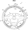
- a reference sign 1 indicating an overall configuration schematically indicates an automotive steering wheel provided with a typical decorative member 20 according to the present embodiment.
- a front surface of the steering wheel 1 will also be referred to as a front portion
- a back surface of the steering wheel 1 will also be referred to as a rear portion
- directions as viewed from the front surface of the steering wheel 1 are referred to as up, down, left, and right.
- the steering wheel 1 includes a cylindrical boss portion 3 fitted and fixed to the leading end of a steering shaft 2, a pad portion 4 attached to an upper portion of the boss portion 3, a ring portion 6 that covers a ring core 5, and spoke portions 8 that partially cover three spoke cores 7 that connect the ring core 5 of the ring portion 6 with the boss portion 3.
- a cover portion 9 made from a resin member such as polyurethane covers an outer circumferential portion of the ring portion 6 and an outer circumferential portion of the spoke portion 8. Attached to the surface of the cover portion 9 are a skin portion 10 made of leather, and the decorative member 20 having a design surface intended to improve an outward appearance design of the steering wheel 1.
- the decorative member 20 illustrated in the drawings is composed of three members including a decorative member 20 provided on the top side, a decorative member 20 provided on the lower left side, and a decorative member 20 provided on the lower right side of the ring portion 6 that is a grip part to be gripped by a driver.
- the decorative member 20 is given. Note that the decorative members 20 provided on the lower left side and lower right side of the ring portion 6 have the same shape and structure as the decorative member 20 provided on top side of the ring portion 6. Accordingly, detailed descriptions of the decorative members 20 provided on the lower left side and lower right side are omitted.
- the decorative member 20 constituting a design portion is formed of a wood material and a cross section of the decorative member 20 is a substantially semi-oval shape.
- the decorative member 20 is bent along the circumferential direction of the ring portion 6 and covers a substantially quadrant portion on the occupant-facing surface of the ring portion 6.
- the back surface of the decorative member 20 is fixed to the cover portion 9 with an adhesive 11.
- the wood material examples include a walnut material, a maple material, a bamboo material, and the like.
- a material of the decorative member 20 is not limited to the wood material, and, for example, various types of resin materials can be used. From the perspective of enhancing the outward appearance design, the front surface of a resin material is preferably decorated with a wood grain pattern or the like. An epoxy-based adhesive or the like can be used as the adhesive 11, for example.
- the decorative member 20 is bonded to the cover portion 9, formed of the resin member such as polyurethane, along the circumferential direction of the cover portion 9 with the adhesive 11.
- a load acts on the steering wheel 1 thus configured, a stress is exerted on a portion of the decorative member 20 adhered with adhesive 11 in response to a deformation of the ring core 5 covered by the cover portion 9.
- the stress concentratedly acts on one site of the decorative member 20 fractures, cracks, or the like can possibly develop in the decorative member 20.
- the strength of the decorative member 20 depends on the material and/or thickness of the decorative member 20. On the other hand, it is effective that an adhesion region (area) of the adhesive 11 is properly determined in order to make a stress exerted on the portion adhered with the adhesive 11 less likely to concentrate on one site of the decorative member 20 when a load acts on the steering wheel 1.
- the adhesion region 12 is provided so that the width thereof is gradually reduced from the central portion 21 on the back surface of the decorative member 20 toward both the circumferential end portions 22 on the left and right sides in the circumferential direction, which makes an adhesion width W2 at the circumferential end portions 22 narrower than an adhesion width W1 at the central portion 21. It is more preferable that the adhesion region 12 be provided on an upper end portion 23 side on an occupant-facing surface of the decorative member 20, which enables the stress that acts on the decorative member 20 to be reduced and the maximum stress to be dispersed.
- the non-adhesion region 13 is provided so that the width thereof is gradually increased from the central portion 21 on the back surface of the decorative member 20 toward both the circumferential end portions 22 on the left and right sides in the circumferential direction.
- a fixing part such as an elastic clip (not illustrated) for fixing the decorative member 20 to the ring portion 6 and/or a backing material (not illustrated) can be provided in the non-adhesion region 13, for example.
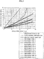
- FIG. 3 shows the relation between ovalization-amounts (mm) of wood members and a wood-developed-stress (MPa) which develops in the wood members.
- the wood members are formed in accordance with improvement proposals 10, 11 (hereinafter, referred to as Embodiments 1, 2 in this order), an evaluation specification, an initial designed configuration, an adhesion region variation, and improvement proposals 1 to 9 (hereinafter, referred to as Comparative Examples 1 to 12 in this order).
- the wood members of Embodiments 1, 2 and Comparative Examples 1 to 12 have various shapes and adhesion regions and are each adhered and fixed to the cover portion 9 of the steering wheel 1.
- the horizontal axis corresponds to the history of an ellipse-amount (ovalization-amount), which indicates the degree of ovalization of a wood member while the vertical axis corresponds to the history of a stress that acts on a wood member relative to a variation in the ovalization-amount.
- the ovalization-amount indicates a difference (mm) between a major axis and a minor axis of an oval cross-section of a wood member.
- the respective wood members of Embodiments 1, 2 are provided with two different adhesion areas, to which an adhesive is applied. As illustrated in FIG. 4A and FIG. 5 , such adhesion areas are gradually reduced in the circumferential direction from the central portion of an upper half of the wood member in a direction along the major axis of the ellipse.
- the wood members of Comparative Examples 1 to 3 include a wood member having a back surface entirely applied with an adhesive, a wood member having various external shapes and adhesion regions, or a wood member having a non-adhered portion formed linearly in the circumferential direction.
- the wood members of Comparative Examples 4 to 7 include a wood member, some portion of which is formed thinner.
- the wood members of Comparative Examples 8 to 11 include a wood member, some portion of which extending in the circumferential direction is formed thinner regardless of an adhered portion with the cover portion 9.
- the wood member of Comparative Example 12 is a backed wood member.
- FIG. 3 clearly shows that an increase rate of the stress that acts on each of the wood members constituting the decorative members of Comparative Examples 1 to 12 is increased along with an increase in the ovalization-amount compared with increase rates of Embodiments 1, 2.
- a stress on the wood members constituting the decorative members of Embodiments 1, 2 gradually increases along with the increase in the ovalization-amount, but is smaller than the stress on the wood members constituting the decorative members of Comparative Examples 1 to 12. In other words, the stress that acts on the decorative members of Embodiments 1, 2 can be kept low regardless of an ellipse-amount.
- FIG. 4A to 4D , FIG. 5 and FIG. 6A, 6B illustrate respective Embodiments of stress distributions in the decorative members 20, 100, resulting from comparisons between a stress that acts on the decorative members 20 of Embodiments 1, 2 and a stress that acts on the decorative members 100 of Comparative Example. Note that these diagrams illustrate half portions of the decorative members 20, 100 in the circumferential direction extending from the central portion 21 to the circumferential end portions 22.
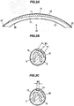
- FIG. 4A illustrates an example of the adhesion region 12 of the decorative member 20 of Embodiment 1
- FIG. 4B, FIG. 4C and FIG. 4D illustrate an example of a distribution of a stress that acts on the decorative member 20.
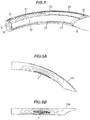
- FIG. 5 illustrates an example of the adhesion region 12 of the decorative member 20 of Embodiment 2.
- FIG. 6A and FIG. 6B illustrate an example of a distribution of a stress that acts on the decorative member 100 as Comparative Example.
- the decorative member 20 of Embodiment 1 illustrated in FIG. 4A is configured so that the adhesion region 12, in which the back surface of the decorative member 20 is adhered and fixed to the cover portion 9, is provided on the upper end portion 23 side on the occupant-facing surface of the decorative member 20 and that the width of the adhesion region 12 is gradually reduced from the central portion 21 on the back surface facing the cover portion 9 of the decorative member 20 toward the circumferential end portions 22.
- an area (maximum stress area) P on which the maximum stress acts in the cross-sectional direction of the decorative member 20 extends in the circumferential direction of the decorative member 20.
- the adhesion region 12, in which the back surface of the decorative member 20 is adhered and fixed to the cover portion 9, is provided on the upper end portion 23 side on the occupant-facing surface of the decorative member 20.
- the width of the adhesion region 12 is gradually reduced from the central portion 21 on the back surface of the decorative member 20 toward the circumferential end portions 22, while the width of the non-adhesion region 13 is gradually increased from the central portion 21 on the back surface of the decorative member 20 toward the circumferential end portions 22.
- the maximum stress that acts on the decorative member 20 can be dispersed and reduced.
- the adhesion width W2 of the circumferential end portions 22 of the decorative member 20 is narrower than the adhesion width W1 of the central portion 21, making the circumferential end portions 22 of the decorative member 20 less likely to follow a deformation of the ring core 5 and thus making the decorative member 20 less likely to deform depending on the extent that the decorative member 20 becomes less likely to follow the deformation of the ring core 5, which allows a stress that acts on the decorative member 20 to be decreased.
- a decorative member 20 having the adhesion region 12 that is gradually reduced in width from the central portion 21 on the back surface facing the cover portion 9 toward the circumferential end portions 22, can be used.
- Such a decorative member 20 has an impact resistance that does not practically cause a trouble.
- the adhesion region 12 of the adhesive 11 for adhering and fixing the back surface of the decorative member 20 to the cover portion 9 is adjusted, so that an impact resistance of the decorative member 20 can be enhanced.
- the adhesion region 12 is provided so that a stress that acts on the portion adhered with the adhesive 11 is less likely to concentrate on one site of the decorative member 20, which causes the stress that acts on the decorative member 20 to be dispersed and reduced even when the stress has acted on the portion adhered with the adhesive 11. Accordingly, a separation at an interface between the decorative member 20 and the cover portion 9 can be less likely to occur.
- the invention is not limited to such a configuration and can of course be effectively applied to various types of work vehicles such as construction machinery, and agricultural machinery.
Landscapes
- Engineering & Computer Science (AREA)
- Chemical & Material Sciences (AREA)
- Combustion & Propulsion (AREA)
- Transportation (AREA)
- Mechanical Engineering (AREA)
- Steering Controls (AREA)
Claims (6)
- Dekoratives Lenkradelement (20), das konfiguriert ist, um auf einem Harzelement montiert zu werden, das einen Umfang eines Ringkerns (5) eines Lenkrads (1) abdeckt, wobei ein Haftbereich (12), in dem das dekorative Element (20) an dem Harzelement haftet, so vorgesehen ist, dass eine Breite des Haftbereichs (12) von einem Mittelabschnitt (21) auf einer dem Harzelement zugewandten Rückseite zu einem Umfangsendabschnitt hin (22) reduziert wird,
dadurch gekennzeichnet, dass die Rückseite des dekorativen Elements (20) einen Nichthaftungsbereich (13) umfasst, in dem das dekorative Element (20) nicht an dem Harzelement haftet, und dass eine Breite des Nichthaftbereichs vom Mittelabschnitt (21) zum Umfangsendabschnitt (22) hin zunimmt. - Dekoratives Lenkradelement (20) nach Anspruch 1, wobei der Haftbereich (12) an einer oberen Endseite (23) auf einer der Insassen zugewandten Oberfläche des dekorativen Elements (20) vorgesehen ist.
- Dekoratives Lenkradelement (20) nach Anspruch 1, wobei das dekorative Element (20) ein Holzmaterial umfasst.
- Dekoratives Lenkradelement (20) nach Anspruch 2, wobei das dekorative Element (20) ein Holzmaterial umfasst.
- Dekoratives Lenkradelement (20) nach Anspruch 1, wobei der Haftbereich (12) so ausgebildet ist, dass seine Breite von einem zum anderen der beiden Umfangsendabschnitte (22) hin abnimmt.
- Dekoratives Lenkradelement (20) nach Anspruch 5, wobei die Rückseite des dekorativen Elements (20) einen Nichthaftungsbereich (13) umfasst, in dem das dekorative Element (20) nicht an dem Harzelement haftet, und
wobei eine Breite des Nichthaftbereichs (13) von dem einen zum anderen der beiden Umfangsendabschnitte (22) zunimmt.
Applications Claiming Priority (1)
| Application Number | Priority Date | Filing Date | Title |
|---|---|---|---|
| JP2016187936A JP6741534B2 (ja) | 2016-09-27 | 2016-09-27 | ステアリングホイール用加飾部材 |
Publications (2)
| Publication Number | Publication Date |
|---|---|
| EP3299252A1 EP3299252A1 (de) | 2018-03-28 |
| EP3299252B1 true EP3299252B1 (de) | 2019-05-15 |
Family
ID=59966613
Family Applications (1)
| Application Number | Title | Priority Date | Filing Date |
|---|---|---|---|
| EP17192825.2A Not-in-force EP3299252B1 (de) | 2016-09-27 | 2017-09-25 | Zierelement eines lenkrades |
Country Status (4)
| Country | Link |
|---|---|
| US (1) | US10179600B2 (de) |
| EP (1) | EP3299252B1 (de) |
| JP (1) | JP6741534B2 (de) |
| CN (1) | CN107867314B (de) |
Families Citing this family (3)
| Publication number | Priority date | Publication date | Assignee | Title |
|---|---|---|---|---|
| JP7060494B2 (ja) * | 2018-11-21 | 2022-04-26 | 豊田合成株式会社 | ステアリングホイール |
| JP7554050B2 (ja) * | 2020-01-14 | 2024-09-19 | 株式会社東海理化電機製作所 | 加飾体 |
| USD968283S1 (en) * | 2022-03-29 | 2022-11-01 | Weize Hong | Car steering wheel decorative cover |
Family Cites Families (13)
| Publication number | Priority date | Publication date | Assignee | Title |
|---|---|---|---|---|
| JP4034447B2 (ja) * | 1998-11-17 | 2008-01-16 | オートリブ株式会社 | 突き板を貼り付けたステアリングホイール |
| JP2000159124A (ja) * | 1998-11-26 | 2000-06-13 | Tokai Rika Co Ltd | ステアリングホイール |
| ITVR20010088A1 (it) * | 2001-08-09 | 2003-02-09 | Dalpa S N C | Procedimento per la fabbricazione di un volante per autoveicoli, e volante fabbricato tramite tale procedimento. |
| JP2005312728A (ja) * | 2004-04-30 | 2005-11-10 | Midori Anzen Co Ltd | 皮革、シフトノブおよびステアリングホイール |
| KR20050123414A (ko) * | 2004-06-25 | 2005-12-29 | 주식회사화이브스타 | 자동차용 조향핸들 및 그 제작 방법 |
| CA2528840A1 (en) * | 2004-12-08 | 2006-06-08 | W.E.T. Automotive Group, Ag | Bezel for heated handle |
| US20060257617A1 (en) * | 2005-04-20 | 2006-11-16 | Worrell Barry C | Method and apparatus for providing a steering wheel with decorative trim |
| JP5415125B2 (ja) * | 2009-04-02 | 2014-02-12 | タカタ株式会社 | ステアリングホイール、ステアリング装置 |
| JP2012253062A (ja) * | 2011-05-31 | 2012-12-20 | Sanyo Electric Co Ltd | 太陽電池モジュール及びその製造方法 |
| JP6283581B2 (ja) * | 2014-06-30 | 2018-02-21 | 日本プラスト株式会社 | ステアリングホイール |
| CN204801864U (zh) * | 2015-07-14 | 2015-11-25 | 宁海尤师傅汽车用品有限公司 | 一种具有按摩透气功能的方向盘套 |
| US20180009462A1 (en) * | 2016-07-08 | 2018-01-11 | Kabushiki Kaisha Tokai Rika Denki Seisakusho | Decorative member for steering wheel |
| JP2018008640A (ja) * | 2016-07-15 | 2018-01-18 | 株式会社東海理化電機製作所 | ステアリングホイール用加飾部材 |
-
2016
- 2016-09-27 JP JP2016187936A patent/JP6741534B2/ja not_active Expired - Fee Related
-
2017
- 2017-09-13 CN CN201710821507.7A patent/CN107867314B/zh not_active Expired - Fee Related
- 2017-09-22 US US15/712,706 patent/US10179600B2/en active Active
- 2017-09-25 EP EP17192825.2A patent/EP3299252B1/de not_active Not-in-force
Non-Patent Citations (1)
| Title |
|---|
| None * |
Also Published As
| Publication number | Publication date |
|---|---|
| US20180086361A1 (en) | 2018-03-29 |
| CN107867314A (zh) | 2018-04-03 |
| JP2018052187A (ja) | 2018-04-05 |
| CN107867314B (zh) | 2021-04-13 |
| EP3299252A1 (de) | 2018-03-28 |
| US10179600B2 (en) | 2019-01-15 |
| JP6741534B2 (ja) | 2020-08-19 |
Similar Documents
| Publication | Publication Date | Title |
|---|---|---|
| US10173713B2 (en) | Steering wheel decorative member | |
| US10179600B2 (en) | Steering wheel decorative member | |
| US20170080772A1 (en) | Stabilizer bushing and bushing-equipped stabilizer bar using the same | |
| US8677858B2 (en) | Steering wheel and manufacturing method of steering wheel | |
| JP5624737B2 (ja) | 非空気入りタイヤ | |
| EP2489581B1 (de) | Windschutzscheibebefestigungsanordnung für ein Sattelfahrzeug | |
| US10252570B2 (en) | Bicycle rim | |
| CN110341376B (zh) | 车辆用轮毂 | |
| US20050264093A1 (en) | Wheel rim with a connecting wall having three arched wall portions | |
| CN101554881A (zh) | 车用方向盘 | |
| WO2018139383A1 (ja) | 車両用シートフレームの構造 | |
| EP3078566B1 (de) | Lenkrad | |
| US11535053B2 (en) | Non-pneumatic tire | |
| JP6368731B2 (ja) | 車両用ホイール | |
| US20060257617A1 (en) | Method and apparatus for providing a steering wheel with decorative trim | |
| JP6402014B2 (ja) | ステアリングホイール | |
| JP5623353B2 (ja) | ステアリングホイール構造 | |
| US4246804A (en) | Steering wheel with splayed leaves | |
| CN110997350A (zh) | 非充气轮胎 | |
| JP2025025290A (ja) | エアレスタイヤ | |
| JP5306804B2 (ja) | ヘッドレスト | |
| US20060213314A1 (en) | Steering wheel with two spoke armature | |
| JP6765207B2 (ja) | キャリパー取り付け構造および自転車 | |
| JPH10230856A (ja) | ステアリングホイール | |
| JPH08133093A (ja) | ステアリングホイール |
Legal Events
| Date | Code | Title | Description |
|---|---|---|---|
| PUAI | Public reference made under article 153(3) epc to a published international application that has entered the european phase |
Free format text: ORIGINAL CODE: 0009012 |
|
| STAA | Information on the status of an ep patent application or granted ep patent |
Free format text: STATUS: THE APPLICATION HAS BEEN PUBLISHED |
|
| AK | Designated contracting states |
Kind code of ref document: A1 Designated state(s): AL AT BE BG CH CY CZ DE DK EE ES FI FR GB GR HR HU IE IS IT LI LT LU LV MC MK MT NL NO PL PT RO RS SE SI SK SM TR |
|
| AX | Request for extension of the european patent |
Extension state: BA ME |
|
| STAA | Information on the status of an ep patent application or granted ep patent |
Free format text: STATUS: REQUEST FOR EXAMINATION WAS MADE |
|
| 17P | Request for examination filed |
Effective date: 20180928 |
|
| RBV | Designated contracting states (corrected) |
Designated state(s): AL AT BE BG CH CY CZ DE DK EE ES FI FR GB GR HR HU IE IS IT LI LT LU LV MC MK MT NL NO PL PT RO RS SE SI SK SM TR |
|
| GRAP | Despatch of communication of intention to grant a patent |
Free format text: ORIGINAL CODE: EPIDOSNIGR1 |
|
| STAA | Information on the status of an ep patent application or granted ep patent |
Free format text: STATUS: GRANT OF PATENT IS INTENDED |
|
| INTG | Intention to grant announced |
Effective date: 20181122 |
|
| GRAS | Grant fee paid |
Free format text: ORIGINAL CODE: EPIDOSNIGR3 |
|
| GRAA | (expected) grant |
Free format text: ORIGINAL CODE: 0009210 |
|
| STAA | Information on the status of an ep patent application or granted ep patent |
Free format text: STATUS: THE PATENT HAS BEEN GRANTED |
|
| AK | Designated contracting states |
Kind code of ref document: B1 Designated state(s): AL AT BE BG CH CY CZ DE DK EE ES FI FR GB GR HR HU IE IS IT LI LT LU LV MC MK MT NL NO PL PT RO RS SE SI SK SM TR |
|
| REG | Reference to a national code |
Ref country code: CH Ref legal event code: EP |
|
| REG | Reference to a national code |
Ref country code: DE Ref legal event code: R096 Ref document number: 602017003917 Country of ref document: DE |
|
| REG | Reference to a national code |
Ref country code: IE Ref legal event code: FG4D |
|
| REG | Reference to a national code |
Ref country code: NL Ref legal event code: MP Effective date: 20190515 |
|
| REG | Reference to a national code |
Ref country code: LT Ref legal event code: MG4D |
|
| PG25 | Lapsed in a contracting state [announced via postgrant information from national office to epo] |
Ref country code: PT Free format text: LAPSE BECAUSE OF FAILURE TO SUBMIT A TRANSLATION OF THE DESCRIPTION OR TO PAY THE FEE WITHIN THE PRESCRIBED TIME-LIMIT Effective date: 20190915 Ref country code: AL Free format text: LAPSE BECAUSE OF FAILURE TO SUBMIT A TRANSLATION OF THE DESCRIPTION OR TO PAY THE FEE WITHIN THE PRESCRIBED TIME-LIMIT Effective date: 20190515 Ref country code: FI Free format text: LAPSE BECAUSE OF FAILURE TO SUBMIT A TRANSLATION OF THE DESCRIPTION OR TO PAY THE FEE WITHIN THE PRESCRIBED TIME-LIMIT Effective date: 20190515 Ref country code: LT Free format text: LAPSE BECAUSE OF FAILURE TO SUBMIT A TRANSLATION OF THE DESCRIPTION OR TO PAY THE FEE WITHIN THE PRESCRIBED TIME-LIMIT Effective date: 20190515 Ref country code: NL Free format text: LAPSE BECAUSE OF FAILURE TO SUBMIT A TRANSLATION OF THE DESCRIPTION OR TO PAY THE FEE WITHIN THE PRESCRIBED TIME-LIMIT Effective date: 20190515 Ref country code: NO Free format text: LAPSE BECAUSE OF FAILURE TO SUBMIT A TRANSLATION OF THE DESCRIPTION OR TO PAY THE FEE WITHIN THE PRESCRIBED TIME-LIMIT Effective date: 20190815 Ref country code: SE Free format text: LAPSE BECAUSE OF FAILURE TO SUBMIT A TRANSLATION OF THE DESCRIPTION OR TO PAY THE FEE WITHIN THE PRESCRIBED TIME-LIMIT Effective date: 20190515 Ref country code: ES Free format text: LAPSE BECAUSE OF FAILURE TO SUBMIT A TRANSLATION OF THE DESCRIPTION OR TO PAY THE FEE WITHIN THE PRESCRIBED TIME-LIMIT Effective date: 20190515 Ref country code: HR Free format text: LAPSE BECAUSE OF FAILURE TO SUBMIT A TRANSLATION OF THE DESCRIPTION OR TO PAY THE FEE WITHIN THE PRESCRIBED TIME-LIMIT Effective date: 20190515 |
|
| PG25 | Lapsed in a contracting state [announced via postgrant information from national office to epo] |
Ref country code: LV Free format text: LAPSE BECAUSE OF FAILURE TO SUBMIT A TRANSLATION OF THE DESCRIPTION OR TO PAY THE FEE WITHIN THE PRESCRIBED TIME-LIMIT Effective date: 20190515 Ref country code: RS Free format text: LAPSE BECAUSE OF FAILURE TO SUBMIT A TRANSLATION OF THE DESCRIPTION OR TO PAY THE FEE WITHIN THE PRESCRIBED TIME-LIMIT Effective date: 20190515 Ref country code: BG Free format text: LAPSE BECAUSE OF FAILURE TO SUBMIT A TRANSLATION OF THE DESCRIPTION OR TO PAY THE FEE WITHIN THE PRESCRIBED TIME-LIMIT Effective date: 20190815 Ref country code: GR Free format text: LAPSE BECAUSE OF FAILURE TO SUBMIT A TRANSLATION OF THE DESCRIPTION OR TO PAY THE FEE WITHIN THE PRESCRIBED TIME-LIMIT Effective date: 20190816 |
|
| REG | Reference to a national code |
Ref country code: AT Ref legal event code: MK05 Ref document number: 1133088 Country of ref document: AT Kind code of ref document: T Effective date: 20190515 |
|
| PG25 | Lapsed in a contracting state [announced via postgrant information from national office to epo] |
Ref country code: AT Free format text: LAPSE BECAUSE OF FAILURE TO SUBMIT A TRANSLATION OF THE DESCRIPTION OR TO PAY THE FEE WITHIN THE PRESCRIBED TIME-LIMIT Effective date: 20190515 Ref country code: CZ Free format text: LAPSE BECAUSE OF FAILURE TO SUBMIT A TRANSLATION OF THE DESCRIPTION OR TO PAY THE FEE WITHIN THE PRESCRIBED TIME-LIMIT Effective date: 20190515 Ref country code: EE Free format text: LAPSE BECAUSE OF FAILURE TO SUBMIT A TRANSLATION OF THE DESCRIPTION OR TO PAY THE FEE WITHIN THE PRESCRIBED TIME-LIMIT Effective date: 20190515 Ref country code: DK Free format text: LAPSE BECAUSE OF FAILURE TO SUBMIT A TRANSLATION OF THE DESCRIPTION OR TO PAY THE FEE WITHIN THE PRESCRIBED TIME-LIMIT Effective date: 20190515 Ref country code: SK Free format text: LAPSE BECAUSE OF FAILURE TO SUBMIT A TRANSLATION OF THE DESCRIPTION OR TO PAY THE FEE WITHIN THE PRESCRIBED TIME-LIMIT Effective date: 20190515 |
|
| REG | Reference to a national code |
Ref country code: DE Ref legal event code: R097 Ref document number: 602017003917 Country of ref document: DE |
|
| PG25 | Lapsed in a contracting state [announced via postgrant information from national office to epo] |
Ref country code: IT Free format text: LAPSE BECAUSE OF FAILURE TO SUBMIT A TRANSLATION OF THE DESCRIPTION OR TO PAY THE FEE WITHIN THE PRESCRIBED TIME-LIMIT Effective date: 20190515 Ref country code: SM Free format text: LAPSE BECAUSE OF FAILURE TO SUBMIT A TRANSLATION OF THE DESCRIPTION OR TO PAY THE FEE WITHIN THE PRESCRIBED TIME-LIMIT Effective date: 20190515 |
|
| PLBE | No opposition filed within time limit |
Free format text: ORIGINAL CODE: 0009261 |
|
| STAA | Information on the status of an ep patent application or granted ep patent |
Free format text: STATUS: NO OPPOSITION FILED WITHIN TIME LIMIT |
|
| PG25 | Lapsed in a contracting state [announced via postgrant information from national office to epo] |
Ref country code: TR Free format text: LAPSE BECAUSE OF FAILURE TO SUBMIT A TRANSLATION OF THE DESCRIPTION OR TO PAY THE FEE WITHIN THE PRESCRIBED TIME-LIMIT Effective date: 20190515 |
|
| 26N | No opposition filed |
Effective date: 20200218 |
|
| PG25 | Lapsed in a contracting state [announced via postgrant information from national office to epo] |
Ref country code: PL Free format text: LAPSE BECAUSE OF FAILURE TO SUBMIT A TRANSLATION OF THE DESCRIPTION OR TO PAY THE FEE WITHIN THE PRESCRIBED TIME-LIMIT Effective date: 20190515 |
|
| PG25 | Lapsed in a contracting state [announced via postgrant information from national office to epo] |
Ref country code: MC Free format text: LAPSE BECAUSE OF FAILURE TO SUBMIT A TRANSLATION OF THE DESCRIPTION OR TO PAY THE FEE WITHIN THE PRESCRIBED TIME-LIMIT Effective date: 20190515 Ref country code: SI Free format text: LAPSE BECAUSE OF FAILURE TO SUBMIT A TRANSLATION OF THE DESCRIPTION OR TO PAY THE FEE WITHIN THE PRESCRIBED TIME-LIMIT Effective date: 20190515 |
|
| PG25 | Lapsed in a contracting state [announced via postgrant information from national office to epo] |
Ref country code: IE Free format text: LAPSE BECAUSE OF NON-PAYMENT OF DUE FEES Effective date: 20190925 Ref country code: LU Free format text: LAPSE BECAUSE OF NON-PAYMENT OF DUE FEES Effective date: 20190925 |
|
| REG | Reference to a national code |
Ref country code: BE Ref legal event code: MM Effective date: 20190930 |
|
| PG25 | Lapsed in a contracting state [announced via postgrant information from national office to epo] |
Ref country code: BE Free format text: LAPSE BECAUSE OF NON-PAYMENT OF DUE FEES Effective date: 20190930 |
|
| PG25 | Lapsed in a contracting state [announced via postgrant information from national office to epo] |
Ref country code: FR Free format text: LAPSE BECAUSE OF NON-PAYMENT OF DUE FEES Effective date: 20190930 |
|
| PG25 | Lapsed in a contracting state [announced via postgrant information from national office to epo] |
Ref country code: RO Free format text: LAPSE BECAUSE OF FAILURE TO SUBMIT A TRANSLATION OF THE DESCRIPTION OR TO PAY THE FEE WITHIN THE PRESCRIBED TIME-LIMIT Effective date: 20190515 |
|
| REG | Reference to a national code |
Ref country code: CH Ref legal event code: PL |
|
| PG25 | Lapsed in a contracting state [announced via postgrant information from national office to epo] |
Ref country code: CY Free format text: LAPSE BECAUSE OF FAILURE TO SUBMIT A TRANSLATION OF THE DESCRIPTION OR TO PAY THE FEE WITHIN THE PRESCRIBED TIME-LIMIT Effective date: 20190515 |
|
| PG25 | Lapsed in a contracting state [announced via postgrant information from national office to epo] |
Ref country code: IS Free format text: LAPSE BECAUSE OF FAILURE TO SUBMIT A TRANSLATION OF THE DESCRIPTION OR TO PAY THE FEE WITHIN THE PRESCRIBED TIME-LIMIT Effective date: 20190915 |
|
| PG25 | Lapsed in a contracting state [announced via postgrant information from national office to epo] |
Ref country code: HU Free format text: LAPSE BECAUSE OF FAILURE TO SUBMIT A TRANSLATION OF THE DESCRIPTION OR TO PAY THE FEE WITHIN THE PRESCRIBED TIME-LIMIT; INVALID AB INITIO Effective date: 20170925 Ref country code: MT Free format text: LAPSE BECAUSE OF FAILURE TO SUBMIT A TRANSLATION OF THE DESCRIPTION OR TO PAY THE FEE WITHIN THE PRESCRIBED TIME-LIMIT Effective date: 20190515 |
|
| PG25 | Lapsed in a contracting state [announced via postgrant information from national office to epo] |
Ref country code: CH Free format text: LAPSE BECAUSE OF NON-PAYMENT OF DUE FEES Effective date: 20200930 Ref country code: LI Free format text: LAPSE BECAUSE OF NON-PAYMENT OF DUE FEES Effective date: 20200930 |
|
| GBPC | Gb: european patent ceased through non-payment of renewal fee |
Effective date: 20210925 |
|
| PG25 | Lapsed in a contracting state [announced via postgrant information from national office to epo] |
Ref country code: MK Free format text: LAPSE BECAUSE OF FAILURE TO SUBMIT A TRANSLATION OF THE DESCRIPTION OR TO PAY THE FEE WITHIN THE PRESCRIBED TIME-LIMIT Effective date: 20190515 |
|
| PG25 | Lapsed in a contracting state [announced via postgrant information from national office to epo] |
Ref country code: GB Free format text: LAPSE BECAUSE OF NON-PAYMENT OF DUE FEES Effective date: 20210925 |
|
| PGFP | Annual fee paid to national office [announced via postgrant information from national office to epo] |
Ref country code: DE Payment date: 20230802 Year of fee payment: 7 |
|
| REG | Reference to a national code |
Ref country code: DE Ref legal event code: R119 Ref document number: 602017003917 Country of ref document: DE |
|
| PG25 | Lapsed in a contracting state [announced via postgrant information from national office to epo] |
Ref country code: DE Free format text: LAPSE BECAUSE OF NON-PAYMENT OF DUE FEES Effective date: 20250401 |