EP3296165A1 - Vorrichtung zur regelung eines windschutzscheibenwischersystems - Google Patents
Vorrichtung zur regelung eines windschutzscheibenwischersystems Download PDFInfo
- Publication number
- EP3296165A1 EP3296165A1 EP16792756.5A EP16792756A EP3296165A1 EP 3296165 A1 EP3296165 A1 EP 3296165A1 EP 16792756 A EP16792756 A EP 16792756A EP 3296165 A1 EP3296165 A1 EP 3296165A1
- Authority
- EP
- European Patent Office
- Prior art keywords
- wiper
- motor
- washer
- windshield
- fets
- Prior art date
- Legal status (The legal status is an assumption and is not a legal conclusion. Google has not performed a legal analysis and makes no representation as to the accuracy of the status listed.)
- Granted
Links
- 239000007788 liquid Substances 0.000 claims abstract description 70
- 230000007246 mechanism Effects 0.000 claims description 33
- 238000005507 spraying Methods 0.000 claims description 10
- 239000007921 spray Substances 0.000 claims description 6
- 239000011521 glass Substances 0.000 description 19
- 238000010586 diagram Methods 0.000 description 15
- 230000009467 reduction Effects 0.000 description 6
- 230000004044 response Effects 0.000 description 4
- 238000004891 communication Methods 0.000 description 3
- 230000005855 radiation Effects 0.000 description 2
- 230000001360 synchronised effect Effects 0.000 description 2
- XLYOFNOQVPJJNP-UHFFFAOYSA-N water Substances O XLYOFNOQVPJJNP-UHFFFAOYSA-N 0.000 description 2
- 229910052782 aluminium Inorganic materials 0.000 description 1
- XAGFODPZIPBFFR-UHFFFAOYSA-N aluminium Chemical compound [Al] XAGFODPZIPBFFR-UHFFFAOYSA-N 0.000 description 1
- 230000015572 biosynthetic process Effects 0.000 description 1
- 230000015556 catabolic process Effects 0.000 description 1
- 230000008859 change Effects 0.000 description 1
- 238000006731 degradation reaction Methods 0.000 description 1
- 230000006866 deterioration Effects 0.000 description 1
- 230000005669 field effect Effects 0.000 description 1
- 230000020169 heat generation Effects 0.000 description 1
- 238000004519 manufacturing process Methods 0.000 description 1
- 229910052751 metal Inorganic materials 0.000 description 1
- 239000002184 metal Substances 0.000 description 1
- 238000000034 method Methods 0.000 description 1
- 238000012986 modification Methods 0.000 description 1
- 230000004048 modification Effects 0.000 description 1
- 238000005406 washing Methods 0.000 description 1
Images


Classifications
-
- B—PERFORMING OPERATIONS; TRANSPORTING
- B60—VEHICLES IN GENERAL
- B60S—SERVICING, CLEANING, REPAIRING, SUPPORTING, LIFTING, OR MANOEUVRING OF VEHICLES, NOT OTHERWISE PROVIDED FOR
- B60S1/00—Cleaning of vehicles
- B60S1/02—Cleaning windscreens, windows or optical devices
- B60S1/04—Wipers or the like, e.g. scrapers
- B60S1/06—Wipers or the like, e.g. scrapers characterised by the drive
- B60S1/08—Wipers or the like, e.g. scrapers characterised by the drive electrically driven
- B60S1/0803—Intermittent control circuits
- B60S1/0807—Intermittent control circuits using electronic control means, e.g. tubes, semiconductors
-
- B—PERFORMING OPERATIONS; TRANSPORTING
- B60—VEHICLES IN GENERAL
- B60S—SERVICING, CLEANING, REPAIRING, SUPPORTING, LIFTING, OR MANOEUVRING OF VEHICLES, NOT OTHERWISE PROVIDED FOR
- B60S1/00—Cleaning of vehicles
- B60S1/02—Cleaning windscreens, windows or optical devices
- B60S1/04—Wipers or the like, e.g. scrapers
- B60S1/06—Wipers or the like, e.g. scrapers characterised by the drive
- B60S1/08—Wipers or the like, e.g. scrapers characterised by the drive electrically driven
-
- B—PERFORMING OPERATIONS; TRANSPORTING
- B60—VEHICLES IN GENERAL
- B60S—SERVICING, CLEANING, REPAIRING, SUPPORTING, LIFTING, OR MANOEUVRING OF VEHICLES, NOT OTHERWISE PROVIDED FOR
- B60S1/00—Cleaning of vehicles
- B60S1/02—Cleaning windscreens, windows or optical devices
- B60S1/46—Cleaning windscreens, windows or optical devices using liquid; Windscreen washers
- B60S1/48—Liquid supply therefor
- B60S1/481—Liquid supply therefor the operation of at least part of the liquid supply being controlled by electric means
- B60S1/482—Liquid supply therefor the operation of at least part of the liquid supply being controlled by electric means combined with the operation of windscreen wipers
Definitions
- the present invention relates to a drive controller for a vehicle wiper system and, more particularly, to a wiper system control device that achieves wiper blade operation control and window washer liquid ejection control in a single control device.
- a wiper blade disposed on a wiping surface is actuated by one or two electric motors.
- two wiper blades on a driver's seat side (DR side) and an assistant's seat side (AS side) are actuated by actuating a link mechanism using one electric motor or by performing synchronous control using two electric motors.
- DR side driver's seat side
- AS side assistant's seat side
- a wiper device is often provided on a rear window as well, and the rear wiper is also driven by an electric motor.
- a window washer device configured to eject washer liquid to a washing surface.
- the washer liquid (window washer liquid) is supplied to a washer nozzle by a pump driven by an electric motor and sprayed onto the wiping surface together with wiping operation of a wiper blade.
- control units are required to control individual electric motors, thus posing problems in terms of on-vehicle layout and device cost.
- a configuration can be considered, where a relay mechanism that drives individual devices is mounted in a front wiper motor, and the motors are controlled by relay operation to reduce the number of the control units required.
- the control units are affected by temperature rise due to heat generation of the motor, making it difficult to perform continuous operation at a high temperature. Further, in spite of increasing the size of the controller, it makes difficult to achieve fine control by ON/OFF operation of the relay mechanism.
- the window washer device is required to eject an optimum amount of the washer liquid onto a glass surface for stable wiping based on uniform water film formation, reduction in the replenishing frequency of the washer liquid, and the like.
- a system that ejects the washer liquid from a wiper arm or a wiper blade and a system that switches the ejection direction of the washer liquid between forward travel and backward travel to always sprinkle the water liquid in the wiper traveling direction have been launched.
- a drive circuit to perform switching of the ejection direction, and thus a control circuit dedicated for the washer is required.
- this control circuit is integrated with the motor, a wide area for mounting control elements and a heat radiation structure are required, resulting in increase in the motor size.
- washer motor an electric motor for the washer liquid
- wiper motor an electric motor for the washer liquid
- the size of a drive circuit is increased to increase the motor size, resulting in degradation in layout efficiency.
- a bridge circuit using four FETs needs to be provided as a drive circuit for the washer motor.
- a control part includes a very large scale circuit having nine FETs, with the result that deterioration in layout efficiency due to increase in the motor size cannot be avoided as above.
- a dedicated module including the nine FETs may be very expensive unless it is expected to be used for other purposes, so that producing the dedicated module is disadvantageous in terms of cost.
- a wiper system control device is a control device of a wiper system provided with at least one wiper motor and at least one other motor different from the wiper motor, the control device being characterized by comprising a FET module incorporating, in one package, at least two FETs for drive of the wiper motor, at least two FETs for drive of the other motor, and at least one FET for circuit protection at the time of power supply reverse connection.
- the wiper system may have a front wiper for wiping a windshield of a vehicle and a front wiper motor for driving the front wiper as the wiper motor
- the FET module may have four FETs for rotationally driving the front wiper motor forward and backward, two FETs for rotationally driving the other motor in one direction, and one FET for circuit protection at the time of power supply reverse connection.
- the wiper system may have a washer nozzle for spraying washer liquid onto the windshield or a rear windshield of a vehicle and a washer motor configured to be rotationally driven in one direction so as to supply the washer liquid to the washer nozzle and to spray the washer liquid onto the vehicle windshield or rear windshield as the other motor.
- the wiper system may have a rear wiper for wiping the vehicle rear windshield and a rear wiper motor for driving the rear wiper as the other motor.
- the wiper system may have two wiper blades for wiping a windshield of a vehicle, a front wiper motor for driving the wiper blades as the wiper motor, and a link mechanism installed between the wiper blades and the front wiper motor to synchronously drive the two wiper blades.
- the wiper system may have two wiper blades for wiping a windshield of a vehicle and two front wiper motors for driving the respective wiper blades as the wiper motor, and the wiper system control device may use two FET modules to synchronously drive the two wiper blades.
- the wiper system may have a washer nozzle for spraying washer liquid onto the windshield or a rear windshield of the vehicle and a washer motor configured to be rotationally driven in one direction so as to supply the washer liquid to the washer nozzle and to spray the washer liquid onto the vehicle windshield or rear windshield as the other motor, and the wiper system control device may use two FETs in each of the two FET modules to form a half-bridge circuit in each of the FET modules and use the two half-bridge circuits to rotationally drive the washer motor forward and backward.
- the wiper system may have a rear wiper for wiping a rear windshield of a vehicle and a rear wiper motor for driving the rear wiper as the other motor, and the wiper system control device may use two FETs in each of the two FET modules to form a half-bridge circuit in each of the FET modules and use the two half-bridge circuits to rotationally drive the rear wiper motor forward and backward.
- the wiper system may have a front wiper for wiping a windshield of a vehicle, a rear wiper for wiping a rear windshield of the vehicle, a washer nozzle for spraying washer liquid onto the windshield or rear windshield, a front wiper motor for driving the front wiper as the wiper motor, and a rear wiper motor and a washer motor as the other motors, the rear wiper motor being a motor for driving the rear wiper, the washer motor being a motor for supplying the washer liquid to the washer nozzle and spraying the washer liquid onto the windshield or rear windshield, and the FET module may have two FETs for rotationally driving the front wiper motor in one direction, two FETs for rotationally driving the rear wiper motor in one direction, two FETs for rotationally driving the washer motor in one direction, and one FET for circuit protection at the time of power supply reverse connection.
- the wiper system may have two wiper blades for wiping the vehicle windshield, a front wiper motor for driving the two wiper blades as the wiper motor, and a link mechanism installed between the wiper blades and the front wiper motor to synchronously drive the two wiper blades.
- the wiper system may have a front wiper for wiping a windshield of a vehicle and a plurality of washer nozzles for spraying washer liquid onto the windshield or rear windshield, a front wiper motor for driving the front wiper as the wiper motor, and a washer motor rotationally driven forward and backward so as to selectively supply the washer liquid to the washer nozzles and to spray the washer liquid onto the vehicle windshield or rear windshield as the other motor, and the FET module may have two FETs for rotationally driving the front wiper motor in one direction, four FETs for rotationally driving the washer motor forward and backward, and one FET for circuit protection at the time of power supply reverse connection.
- the wiper system may have a front wiper for wiping a windshield of a vehicle and a rear wiper for wiping a rear windshield of the vehicle, a front wiper motor for driving the front wiper as the wiper motor, and a rear wiper motor for driving the rear wiper as the other motor, and the FET module may have two FETs for rotationally driving the front wiper motor in one direction, four FETs for rotationally driving the rear wiper motor forward and backward, and one FET for circuit protection at the time of power supply reverse connection.
- the wiper system may have a front wiper for wiping a windshield of a vehicle and a front wiper motor for driving the front wiper as the wiper motor, and the FET module may be mounted on a control board incorporated in the front wiper motor.
- the control board may have thereon a rotation signal transmitting/receiving part for transmitting and receiving a signal to rotate the other motor.
- the wiper motor and the other motor may be connected to each other through a signal transmitting part for transmitting the signal.
- the FET module may be a module for driving a three-phase brushless motor provided with seven FETs.
- the module for driving a three-phase brushless motor it is possible to constitute the control device of the invention with general-purpose components, thus eliminating the need to produce dedicated electronic components, which leads to reduction in production cost.
- the wiper system control device uses a FET module incorporating, in one package, at least two FETs for drive of the wiper motor, at least two FETs for drive of the other motor, and at least one FET for circuit protection at the time of power supply reverse connection.
- the object of the embodiments described below is to provide a wiper system control device capable of achieving operation control of a wiper blade and ejection control of window washer liquid with a compact configuration.
- FIG. 1 is an explanatory view illustrating the configuration of a wiper system 1 according to a first embodiment.
- the wiper system is drive-controlled by a control device provided by the present invention.
- the wiper system 1 has a front wiper and a window washer device.
- the control device uses one FET (Field Effect Transistor) module to rotationally drive one front wiper motor forward and backward and rotationally drive one washer motor in one direction.
- FET Field Effect Transistor
- the wiper system 1 has a driver's seat side wiper arm 2a and an assistant's seat side wiper arm 2b.
- the wiper arms 2a and 2b are connected to each other by a link mechanism 3.
- the wiper arms 2a and 2b are attached with wiper blades 4a and 4b, respectively, for wiping a glass surface.
- the wiper blades 4a and 4b are brought into elastic contact with a windshield (wiping surface) 5 by unillustrated spring members or the like incorporated in the wiper arms 2a and 2b.
- the link mechanism 3 is connected to a motor unit 6.
- the wiper blades 4a and 4b are driven by the motor unit 6 through the link mechanism 3.
- the wiper system 1 is further provided with a window washer device 15.
- the window washer device 15 has washer nozzles 16 that eject washer liquid onto the glass surface and a washer pump 17 for supplying the washer liquid to the washer nozzles 16.
- the washer pump 17 is driven by a washer motor (other motor) 18 and supplies the washer liquid stored in a washer tank 19 to the washer nozzles 16 at a predetermined pressure.
- the washer liquid is sprayed from the washer nozzles 16 at a pressure according to the rotating speed of the washer motor 18.
- the motor unit 6 has a wiper motor (front wiper motor) 7 and a decelerating mechanism 8.
- the wiper motor 7 is provided with a sensor for detecting the relative positions of the wiper blades 4a and 4b.
- the decelerating mechanism 8 is provided with a sensor for detecting the absolute positions (e.g., lower inversion position) of the wiper blades 4a and 4b.
- the relative position detecting sensor outputs a pulse signal with rotation of the motor.
- the absolute position detecting sensor outputs a signal corresponding to the positions of the wiper blades 4a and 4b.
- FIG. 2 is an explanatory view illustrating the configuration of the controller 9.
- the controller 9 is provided with a FET module 10, a rotation signal transmitting/receiving part 20, and a control board 11 mounting an unillustrated sensor and the like thereon.
- a metal heat plate 12 formed of, e.g., aluminum is mounted to the FET module 10.
- One end side of the heat plate 12 contacts a frame 13 of the motor unit 6, and heat generated in the FET module 10 is radiated to the frame 13 through the heat plate 12. This eliminates the need to increase the size of the control board 11 in consideration of heat radiation, thereby achieving miniaturization of the controller 9.
- FIG. 3 is a block diagram illustrating the circuit configuration of the controller 9.
- the controller 9 has a CPU 21 in which a control program is installed, together with the FET module 10 and the rotation signal transmitting/receiving part 20.
- the controller 9 further has a ROM 22 storing various control data therein, a first drive circuit 23, and a second drive circuit 24.
- the CPU 21 calculates position information (current positions) of the wiper blades 4a and 4b based on signals output from the respective sensors and controls forward and backward rotational drive of the wiper motor 7 or rotating speed thereof while referring to the control data stored in the ROM 22.
- the CPU 21 controls the washer motor 18 by a signal transmitted thereto from the rotation signal transmitting/receiving part 20 through a signal line 25 in conjunction with operation of an unillustrated window washer switch. Under such control, washer liquid is ejected onto the glass surface appropriately. In place of the signal line 25, a signal may be transmitted/received by wireless.
- the controller 9 uses, as the FET module 10, a general-purpose FET module used for driving a three-phase brushless motor.
- the FET module for the three-phase drive includes a total of seven FETs (one reverse connection protection FET and three sets of two FETs for driving each phase). That is, six FETs are mounted on the general-purpose FET module in addition to the reverse connection protection FET.
- the wiper system four FETs and two FETs are required respectively for forward and backward rotational drive of the wiper motor 7 and for drive of the washer motor 18.
- the present inventor found that the number of the three-phase drive FETs of the general-propose module and the number of FETs required for the wiper motor and washer motor are each six and came to the conclusion that the general-purpose FET module is applied to control of the wiper system.
- the controller 9 uses four FETs for forward and backward rotational drive of the wiper motor 7 and uses the remaining two FETs for drive of the washer motor 18.
- the FET module 10 is partitioned into a battery reverse connection protection part 31, a wiper motor drive part 32, and a washer motor drive part 33.
- the battery reverse connection protection part 31 is provided with one FET 34a
- the wiper motor drive part 32 is provided with four FETs 34b to 34e
- the washer motor drive part 33 is provided with two FETs 34f and 34g.
- a bridge circuit for forward and backward rotational drive of the wiper motor 7 is formed by the FETs 34b to 34e.
- the FETs 34b to 34e are turned ON/OFF appropriately by the CPU (Central Processing Unit) 21 and first and second drive circuits 23 and 24 based on the position information of the wiper blades 4a and 4b to thereby control forward and backward rotational drive of the wiper motor 7. Further, the FETs 34f and 34g are turned ON/OFF appropriately by the CPU 21 and the first and second drive circuits 23 and 24 in conjunction with operation of the window washer switch to thereby control operation of the washer motor 18. Under the above control, the wiper blades 4a and 4b perform reciprocating wiping operation on the glass surface and washer liquid is ejected onto the glass surface in response to the switch operation.
- the CPU Central Processing Unit
- the general-purpose FET module for three-phase motor drive is diverted to control of the wiper system, whereby the controller 9 can be constituted by a FET module incorporating the wiper drive FETs, washer drive FETs, and reverse connection protection FET in one package.
- the controller 9 can be constituted by a FET module incorporating the wiper drive FETs, washer drive FETs, and reverse connection protection FET in one package.
- FIG. 4 is an explanatory view illustrating the configuration of a wiper system 40.
- the wiper system 40 is also drive-controlled by the control device provided by the present invention.
- the wiper system 40 has a front wiper and a window washer device.
- the control device uses two FET modules to rotationally drive two front wiper motors forward and backward and rotational ly drive one washer motor forward and backward.
- the wiper system 40 is an opposing wiping type wiper system, in which a driver's seat side (DR side) wiper arm 41a and an assistant's seat side (AS side) wiper arm 41b are disposed opposite to each other.
- the wiper arms 41a and 41b are attached with wiper blades 42a and 42b, respectively.
- the wiper blades 42a and 42b are brought into elastic contact with a windshield 43 by unillustrated spring members or the like incorporated in the wiper arms 41a and 41b.
- Two wiper shafts (pivot shafts) 44a and 44b are fixed to a vehicle body.
- the base end portions of the wiper arms 41a and 41b are fixed to the wiper shafts 44a and 44b, respectively, thereby forming a so-called direct drive wiper.
- the symbols "a” and “b” attached to the reference numerals indicate components or portions provided on the driver's seat side and the assistant's seat side, respectively.
- the wiper system 40 has two motor units 46a and 46b which are subjected to PWM (Pulse Width Modulation) duty control.
- the motor units 46a and 46b each include a wiper motor (front wiper motor) (47a, 47b) and a decelerating mechanism 48.
- the wiper motors 47a and 47b are drive-controlled by controllers (wiper system control devices) 50a and 50b, respectively, to be rotationally driven forward and backward.
- controllers 50a and 50b are integrally provided in the motor units 46a and 46b, respectively, and each have a control board like one illustrated in FIG. 2 .
- the controllers in the following embodiments have the same configuration.
- the controller 50a that drive-controls the wiper motor 47a is connected to an ECU (Engine Control Unit) 71 as a vehicle side controller through an on-vehicle LAN (Local Area Network) 72.
- Switch information such as ON/OFF, Lo, Hi, INT (intermittent operation) or the like of a wiper switch, engine start-up information, and the like are input from the ECU 71 to the controller 50a through the LAN 72.
- the wiper controllers 50a and 50b are connected to each other through a communication line 73.
- the wiper motors 47a and 47b are feedback-controlled (PI-controlled) based on position information of the wiper blades 42a and 42b, respectively.
- target speeds of both blades are set according to the positions of the respective wiper blades 42a and 42b.
- the target speeds are previously stored in the respective controllers 50a and 50b in the form of a map or the like.
- the controllers 50a and 50b detect current positions of the respective wiper blades 42a and 42b and detects moving speeds of the respective wiper blades 42a and 42b from rotating speeds of the respective wiper shafts 44a and 44b.
- the rotating speeds of the wiper shafts 44a and 44b are each detected by a sensor magnet (not illustrated) mounted to the wiper shaft (44a, 44b) or the rotary axis of the wiper motor (47a, 47b) and a magnetic sensor (not illustrated) disposed opposite to the sensor magnet.
- the controllers 50a and 50b compare the current speeds of the wiper blades 42a and 42b with the target speeds of the wiper blades 42a and 42b at the positions where the current speeds are detected and appropriately control the respective wiper motors 47a and 47b according to a difference between the target speed and the current speed.
- Control information of the wiper motors 47a and 47b is exchanged between the controllers 50a and 50b through the communication line 73, and the wiper motors 47a and 47b are subjected to synchronous control based on the positional relationship between the blades. That is, the controllers 50a and 50b control forward and backward rotational drive of the wiper motors 47a and 47b, respectively, based on the positions of their corresponding blades and, at the same time, control the wiper motors 47a and 47b based on the blade position information of the wiper blades 42a and 42b to thereby control the wiper system so as not to cause interference between the blades or not to increase a difference in angle therebetween. As a result, the wiper blades 42a and 42b are each brought into swing movement between a lower inversion position and an upper inversion position within a wiping range 45, whereby rain or snow adhered to the windshield 43 is wiped away therefrom.
- washer nozzles 55 for ejecting washer liquid onto the glass surface are formed in each of the wiper blades 42a and 42b.
- the washer nozzles 55 are supplied with washer liquid from a washer pump 56.
- the washer pump 56 is driven by a washer motor (other motor) 57 to supply washer liquid stored in a washer tank 58 to the washer nozzles 55 at a predetermined pressure.
- the washer liquid is sprayed from the washer nozzles 55 at a pressure according to the rotating speed of the washer motor 57.
- the washer motor 57 is drive-controlled by a signal transmitted thereto from a rotation signal transmitting/receiving part 60 of each of the controllers 50a and 50b through a signal line 59.
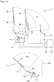
- FIG. 5 is an explanatory view illustrating the configuration of the washer nozzles 55.
- the washer nozzles 55 are formed in both side surfaces of each of the wiper blades 42a and 42b.
- Washer nozzles 55f are formed in one surface side of each of the wiper blades 42a and 42b, and washer nozzles 55r are formed in the other surface side thereof. Washer liquid is ejected from the nozzles on the front side in the travel direction of each of the wiper blades 42a and 42b.
- FIG. 6 is a block diagram illustrating the circuit configurations of the respective controllers 50a and 50b.
- the controller 50a and the controller 50b are a DR-side controller and an AS-side controller, respectively, and have the same configuration.
- the controllers 50a and 50b are provided with CPUs 51a and 51b each in which a control program is installed, together with FET modules 54a and 54b and the rotation signal transmitting/receiving part 60.
- the controllers 50a and 50b are provided with first drive circuits 52a and 52b and second drive circuits 53a and 53b, respectively.
- various control data are stored in the vehicle-side ECU 71.
- the CPUs 51a and 51b calculate position information (current positions) of the wiper blades 42a and 42b based on signals output from the respective sensors and controls forward and backward rotational drive of the wiper motors 47a and 47b or rotating speeds thereof while referring to the control data stored in the ECU 71. Further, the CPUs 51a and 51b control forward and backward rotational drive of the washer motor 57 or rotating speed thereof by a signal transmitted thereto from the rotation signal transmitting/receiving part 60 through the signal line 59 in conjunction with operation of an unillustrated window washer switch. Under such control, washer liquid is ejected onto the glass surface appropriately from the washer nozzles 55f or 55r.
- the general-purpose FET module used for driving a three-phase brushless motor is used as each of FET modules 54a and 54b of the respective controllers 50a and 50b.
- the FET module for the three-phase drive includes a total of seven FETs (one reverse connection protection FET and three sets of two FETs for driving each phase) .
- the wiper system according to the second embodiment four FETs are required for forward and backward rotational drive of the wiper motor 7, and a total of eight FETs are required for DR and AS. Further, four FETs are required for forward and backward rotational drive of the washer motor 57.
- the controllers 50a and 50b use four FETs for forward and backward rotational drive of the wiper motors 47a and 47b, and use the remaining four FETs (two FETs and two FETs) for forward and backward rotational drive of the washer motor 57.
- the FET modules 54a and 54b are partitioned into battery reverse connection protection parts 61a and 61b, (front) wiper motor drive parts 62a and 62b, and washer motor drive parts 63a and 63b, respectively.
- the battery reverse connection protection parts 61a and 61b are provided with one FET 64a and one FET 65a, respectively, the wiper motor drive parts 62a and 62b are provided with four FETs 64b to 64e and four FETs 65b to 65e, respectively, and washer motor drive parts 63a and 63b are provided with two FETs 64f and 64g and two FETs 65f and 65g, respectively.
- bridge circuits for forward and backward rotational drive of the respective wiper motors 47a and 47b are formed by the FETs 64b to 64e and FETs 65b to 65e, respectively.
- two half-bridge circuits are formed by two FETs 64f and 64g and two FETs 65f and 65g, respectively.
- a bridge circuit for forward and backward rotational drive of the washer motor 57 is formed by the two half-bridge circuits.
- the FETs 64b to 64e and FETs 65b to 65e are turned ON/OFF appropriately by the CPU 51a and CPU 51b, and first and second drive circuits 52a and 52b and first and second drive circuits 53a and 53b based on the position information of the wiper blades 42a and 42b to thereby control forward and backward rotational drive of the wiper motors 47a and 47b.
- the wiper blades 42a and 42b perform reciprocating wiping operation on the glass surface.
- the FETs 64f and 64g and FETs 65f and 65g are turned ON/OFF appropriately by the CPU 51a and CPU 51b and first and second drive circuits 52a and 52b and first and second drive circuits 52a and 53b in conjunction with operation of the window washer switch to thereby control forward and backward rotational drive of the washer motor 57.
- washer liquid is selectively supplied to the nozzles 55f and 55r in sync with movement of the wiper blades 42a and 42b and appropriately ejected onto the glass surface toward the blade travel direction.
- the general-purpose FET module for three-phase motor drive is diverted to control of the wiper system, whereby each of the controllers 50a and 50b can be constituted by a FET module incorporating the wiper drive FETs, washer drive FETs, and reverse connection protection FET in one package.
- a compact controller capable of controlling both the wiper motor and the washer motor without involving increase in the size of the drive circuit.
- a circuit capable of achieving fine ejection control e.g., switching the ejection direction between the forward travel and backward travel
- the size of the motor can be reduced.
- a wiper system 80 according to the third embodiment includes a front wiper and a rear wiper, and the control device uses one FET module to rotationally drive one front wiper motor forward and backward and rotationally drive one rear wiper motor in one direction.
- the rear wiper motor is drive-controlled by a controller using one FET module so as to achieve efficient layout or reduce the number of components.
- FIG. 7 is an explanatory view illustrating the configuration of the wiper system 80 according to the third embodiment.
- a front wiper 81 of the wiper system 80 is a parallel wiping type wiper device rotationally driven forward and backward by one motor.
- the front wiper 81 has the driver's seat side wiper arm 2a, assistant's seat side wiper arm 2b, and wiper blades (front wiper blades) 4a and 4b.
- the wiper blades 4a and 4b on the windshield 5 are driven by a front wiper motor (motor for front wiper) 82 through the link mechanism 3.
- the front wiper motor 82 is controlled by a controller (wiper system control device) 83 provided with the FET module 10.
- the front wiper motor 82 and controller 83 are integrated with the decelerating mechanism 8 to constitute a motor unit 84.
- the motor unit 84 is disposed in a vehicle body.
- the wiper system 80 is provided with a rear wiper 85 in addition to the front wiper 81.
- the rear wiper 85 is disposed on a rear windshield 86 at the vehicle rear side and has a wiper arm 87 and a rear wiper blade 88.
- the wiper arm 87 and the rear wiper blade 88 are driven by a rear wiper motor (motor for rear wiper: other motor) 91 for rotationally driving them in one direction through a link mechanism 89.
- the rear wiper motor 91 and the front wiper 82 are controlled by the same controller 83.
- a crank mechanism, a swinging mechanism using a sector gear, or the like may be incorporated in the rear wiper motor 91 for rotational drive.
- FIG. 8 is block diagram illustrating the circuit configuration of the controller 83.
- the controller 83 has the CPU 21, ROM (Read Only Memory) 22, first drive circuit 23, second drive circuit 24, FET module 10, and rotation signal transmitting/receiving part 20, like the controller 9 according to the first embodiment.
- the CPU 21 calculates position information (current positions) of the wiper blades 4a and 4b and controls forward and backward rotational drive of the front wiper motor 82 or rotating speed thereof while referring to the control data stored in the ROM 22.
- the CPU 21 controls the rear wiper motor 91 by a signal transmitted thereto from the rotation signal transmitting/receiving part 20 through the signal line 25 in conjunction with operation of an unillustrated rear wiper switch and actuates the rear wiper blade 88 of the rear wiper 85 on the rear windshield 86.
- the controller 83 also uses, as the FET module 10, a general-purpose FET module used for driving a three-phase brushless motor.
- the FET module 10 a general-purpose FET module used for driving a three-phase brushless motor.
- the wiper system 80 four FETs and two FETs are required respectively for forward and backward rotational drive of the wiper motor 82 and for drive of the rear wiper motor 91.
- the general-purpose FET module can be applied to control of the wiper system 80.
- the controller 83 uses four FETs for forward and backward rotational drive of the front wiper motor 82 and uses the remaining two FETs for drive of the rear wiper motor 91.
- the FET module 10 is partitioned into the battery reverse connection protection part 31, a front wiper motor drive part 92, and a rear wiper motor drive part 93.
- the battery reverse connection protection part 31 is provided with one FET 34a
- the front wiper motor drive part 92 is provided with four FETs 34b to 34e
- the rear wiper motor drive part 93 is provided with two FETs 34f and 34g.
- a bridge circuit for forward and backward rotational drive of the front wiper motor 82 is formed by the FETs 34b to 34e.
- the FETs 34b to 34e are turned ON/OFF appropriately by the CPU 21 and the first and second drive circuits 23 and 24 based on the position information of the wiper blades 4a and 4b to thereby control forward and backward rotational drive of the front wiper motor 82. Further, the FETs 34f and 34g are turned ON/OFF appropriately by the CPU 21 and the first and second drive circuits 23 and 24 in conjunction with operation of a rear wiper switch to thereby control operation of the rear wiper motor 91. Under the above control, the wiper blades 4a and 4b perform reciprocating wiping operation on the glass surface and the rear wiper motor 91 also performs reciprocating wiping operation on the rear windshield 86 in response to the switch operation.
- the front wiper motor 82 and the rear wiper motor 91 are controlled by the same controller 83.
- diversion of the general-purpose FET module for three-phase motor drive allows the controller 83 to be constituted by a FET module incorporating the front wiper drive FETs, rear wiper drive FETs, and reverse connection protection FET in one package.
- the controller 83 it is possible to realize a compact controller capable of controlling both the front wiper motor 82 and the rear wiper motor 91 without involving increase in the size of the drive circuit.
- the motor size can be reduced.
- efficient layout of the wiper system can be achieved.
- FIG. 9 is an explanatory view illustrating the configuration of a wiper system 95 according to a fourth embodiment of the present invention.
- the wiper system 95 has a front wiper and a rear wiper.
- the control device in the present embodiment uses two FET modules to rotationally drive two front wiper motors forward and backward and rotationally drive one rear wiper motor forward and backward.
- the wiper system 95 has an opposing wiping type front wiper 96 like the one illustrated in FIG. 4 and the rear wiper 85.
- the wiper arms 41a and 41b of the front wiper 96 are driven by the motor units 46a and 46b, respectively.
- the motor units 46a and 46b are provided with the wiper motors 47a and 47b, respectively, and controllers 97a and 97b, respectively.
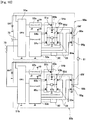
- FIG. 10 is a block diagram illustrating the circuit configurations of the respective controllers 97a and 97b.
- the controllers 97a and 97b have the same configuration as each other and that of the controllers 50a and 50b of FIG. 6 ; however, the object to be drive-controlled by the half-bridge circuit is not set to the washer motor, but set to the rear wiper motor 91. That is, the washer motor drive parts 63a and 63b of FIG. 6 is replaced with rear wiper motor drive parts 98a and 98b.
- the FET modules 54a and 54b are partitioned into the battery reverse connection protection parts 61a and 61b, front wiper motor drive parts 62a and 62b, and rear wiper motor drive parts 98a and 98b, respectively.
- the battery reverse connection protection parts 61a and 61b are provided with one FET 64a and one FET 65a, respectively
- the front wiper motor drive parts 62a and 62b are provided with four FETs 64b to 64e and four FETs 65b to 65e, respectively
- the rear wiper motor drive parts 98a and 98b are provided with two FETs 64f and 64g and two FETs 65f and 65g, respectively.
- two half-bridge circuits are formed by the two FETs 64f and 64g and two FETs 65f and 65g, respectively.
- Abridge circuit for forward and backward rotational drive of the rear wiper motor 91 is formed by the two half-bridge circuits.
- the general-purpose FET module for three-phase motor drive is diverted to control of the wiper system to constitute each of the controllers 72a and 72b.
- the general-purpose FET module for three-phase motor drive is diverted to control of the wiper system to constitute each of the controllers 72a and 72b.
- FIG. 11 is an explanatory view illustrating the configuration of a wiper system 100 according to a fifth embodiment of the present invention.
- the wiper system 100 has a front wiper 101 for wiping the windshield and a rear wiper 111 for wiping the rear windshield.
- the front wiper 101 has the same configuration as the front wiper in the wiper system of FIG. 1 and includes the window washer device 15.
- the window washer device 15 is driven by the washer motor (other motor) 18.
- the control device in the present embodiment uses one FET module to rotationally drive one front wiper motor, one rear wiper motor, and one washer motor in one direction.
- the rear wiper 111 has a wiper arm 112.
- the wiper arm 112 is attached with a wiper blade 113 for wiping the glass surface.
- the wiper blade 113 is also brought into elastic contact with a rear windshield 114 by an unillustrated spring member or the like incorporated in the wiper arm 112.
- the wiper arm 112 is connected to a motor unit 116 through a link mechanism 115.
- the wiper blade 113 is driven by the motor unit 116.
- the motor unit 6 has the front wiper motor (motor for front wiper) and the decelerating mechanism 8, and the motor unit 116 has a rear wiper motor 117 (motor for rear wiper: other motor) and a decelerating mechanism 118.
- the motor unit 6 is integrally provided with a controller (wiper system control device) 102, and both the wiper motors 7 and 117 and washer motor 18 are controlled by the controller 102.
- the internal configuration of the controller 9 is the same as that illustrated in FIG. 2 .
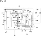
- FIG. 12 is a block diagram illustrating the circuit configuration of the controller 102.
- the controller 102 has a CPU 121 in which a control program is installed.
- the CPU 121 is connected to an unillustrated vehicle-side controller (ECU) through an on-vehicle LAN 122.
- the controller 9 further has a first drive circuit 123, a second drive circuit 124, a FET module 110, and the rotation signal transmitting/receiving part 20.
- the CPU 121 controls ON/OFF or rotating speeds of the wiper motors 7 and 117 according to an instruction issued by the ECU.
- the CPU 121 controls the washer motor 18 by a signal transmitted thereto from the rotation signal transmitting/receiving part 20 through a signal line 25 in conjunction with operation of an unillustrated window washer switch. Under such control, washer liquid is ejected onto the glass surface appropriately.
- the controller 102 uses two FETs for drive of the front wiper motor 7, uses two FETs for drive of the rear wiper motor 117, and uses the remaining two FETs for drive of the washer motor 18.
- the FET module 110 is partitioned into a battery reverse connection protection part 131, a front wiper motor drive part 132, a rear wiper motor drive part 133, and a washer motor drive part 134.
- the battery reverse connection protection part 131 is provided with one FET 135a
- the front wiper motor drive part 132 is provided with two FETs 135b and 135c
- the rear wiper motor drive part 133 is provided with two FETs 135d and 135e
- the washer motor drive part 134 is provided with two FETs 135f and 135g.
- the FETs 135b and 135c are turned ON/OFF appropriately by the CPU 121, and the first and second drive circuits 123 and 123 to thereby control operation of the front wiper motor 7.
- the FETs 135d and 135e are turned ON/OFF appropriately by the CPU 121 and the first and second drive circuits 123 and 123 123 to thereby control operation of the rear wiper motor 117.
- the FETs 135f and 135g are turned ON/OFF appropriately by the CPU 121, and the first and second drive circuits 123 and 123 in conjunction with operation of the window washer switch to thereby control operation of the washer motor 18 .
- the wiper blades 4a and 4b perform reciprocating wiping operation on the windshield
- the wiper blade 113 performs reciprocating wiping operation on the rear windshield
- washer liquid is appropriately ejected onto the glass surface in response to the switch operation.
- the general-purpose FET module for three-phase motor drive is diverted to control of the wiper system to constitute the controller 102 by an FET module incorporating the front wiper drive FET, rear wiper drive FET, and washer drive FET, and reverse connection protection FET in one package.
- an FET module incorporating the front wiper drive FET, rear wiper drive FET, and washer drive FET, and reverse connection protection FET in one package.
- FIG. 13 is an explanatory view illustrating the configuration of a wiper system 141 according to the sixth embodiment.
- the control device in the present embodiment uses one FET module to rotationally drive one front wiper motor in one direction and rotationally drive one washer motor forward and backward.
- the wiper system 141 has a driver's seat side wiper arm 142a and an assistant's seat side wiper arm 142b.
- the wiper arms 142a and 142b are connected to each other by a link mechanism 143.
- the wiper arms 142a and 142b are attached with wiper blades 144a and 144b, respectively, for wiping the glass surface.
- the wiper blades 144a and 144b are brought into elastic contact with a windshield 145.
- the link mechanism 143 is connected to a motor unit 146.
- the wiper blades 144a and 144b are driven by the motor unit 146.
- washer nozzles 151 (151f: first washer nozzles, 151r: second washer nozzles) for ejecting washer liquid onto the glass surface are formed in each of the wiper blades 144a and 144b.
- the washer nozzles 151 are supplied with washer liquid from a washer pump 152.
- the washer pump 152 is driven by a washer motor (other motor) 153 to supply washer liquid stored in a washer tank 154 to the washer nozzles 151 at a predetermined pressure.
- the washer liquid is sprayed from the washer nozzles 151 at a pressure according to the rotating speed of the washer motor 153.
- the washer nozzles 151 are formed in both side surfaces of each of the wiper blades 144a and 144b. Washer nozzles 151f are formed in one surface side of each of the wiper blades 144a and 144b, and washer nozzles 151r are formed in the other surface side thereof. Washer liquid is ejected from the nozzles on the front side in the travel direction of each of the wiper blades 144a and 144b.
- the motor unit 146 has a wiper motor 147 and a decelerating mechanism 148.
- the motor unit 146 is integrally provided with a controller (wiper system control device) 149. Both the wiper motor 147 and the washer motor 153 are controlled by the controller 149.
- the controller 149 has the same configuration as the controller 9 illustrated in FIG. 2 and is provided with the control board 11 mounting a FET module 160 and the like thereon.
- FIG. 14 is a block diagram illustrating the circuit configuration of the controller 149.
- the controller 149 has a CPU 161 in which a control program is installed.
- the CPU 161 is connected to an unillustrated vehicle-side controller (ECU) through an on-vehicle LAN 162.
- the controller 149 further has a first drive circuit 163, a second drive circuit 164, a FET module 160, and the rotation signal transmitting/receiving part 20.
- the CPU 161 controls ON/OFF or rotating speed of the wiper motor 147 based on an instruction issued by the ECU. Further, the CPU 161 controls forward and backward rotation or rotating speed of the washer motor 153 in conjunction with operation of an unillustrated window washer switch. Under such control, washer liquid is ejected onto the glass surface appropriately from the washer nozzles 151f or 151r.
- the general-purpose FET module used for driving a three-phase brushless motor is used as the FET module 160 of the controller 149.
- the wiper system 141 two FETs are used for rotationally driving the wiper motor 147 in one direction, and four FETs are used to rotationally drive the washer motor 153 forward and backward. That is, of the six FETs for drive of the respective phases, and two FETs are used for drive (unidirectional rotation) of the wiper motor 147 and the remaining four FETs for forward and backward rotational drive of the washer motor 153. As illustrated in FIG.
- the FET module 160 is partitioned into a battery reverse connection protection part 165, a (front) wiper motor drive part 166, and a washer motor drive part 167.
- the battery reverse connection protection part 165 is provided with one FET 168a
- the wiper motor drive part 166 is provided with two FETs 168b and 168c
- the washer motor drive part 167 is provided with four FETs 168d to 168g.
- a bridge circuit for forward and backward rotational drive of the washer motor 153 is formed by the FETs 168d to 168g.
- the FETs 168b and 168c are turned ON/OFF appropriately by the CPU 161 and the first and second drive circuits 163 and 164 to thereby control operation of the wiper motor 147. Further, the FETs 168d to 168g are turned ON/OFF appropriately by the CPU 161 and the first and second drive circuits 163 and 164 in conjunction with operation of the window washer switch to thereby control forward and backward rotational drive of the washer motor 153.
- the wiper arms 142a and 142b perform reciprocating wiping operation on the glass surface and washer liquid is ejected onto the glass surface appropriately toward the blade travel direction in sync with movement of the wiper arms 142a and 142b.
- the general-purpose FET module for three-phase motor drive is diverted to control the wiper system to constitute the controller 149 by a FET module incorporating the wiper drive FETs, washer drive FETs, and reverse connection protection FET in one package.
- a compact controller capable of controlling both the wiper motor and the washer motor without involving increase in the size of the drive circuit.
- a circuit capable of achieving fine ejection control e.g., switching the ejection direction between the forward travel and the backward travel) of the washer liquid in a compact layout.
- washer liquid is ejected while switching between the washer nozzles 151f and 151r formed on both side surfaces of each of the wiper blades 144a and 144b by forward and backward rotational drive of the washer motor 153; alternatively, however, washer liquid may be ejected while switching between the washer nozzles formed on the front side and rear side by forward and backward rotational drive of the washer motor.
- FIG. 15 is an explanatory view illustrating the configuration of a wiper system 170 according to a seventh embodiment of the present invention.
- the wiper system 170 has the front wiper 101 and the rear wiper 111.
- the control device in the present embodiment uses one FET module to rotationally drive one front wiper motor in one direction and rotationally drive one rear wiper motor forward and backward.
- the configurations of the front wiper 101 and the rear wiper 111 are the same as those in the wiper system 100 of FIG. 11 .
- the window washer device 15 of FIG. 11 is not set as a control target.
- the front wiper 101 is driven by the front wiper motor 7, and the rear wiper 111 is driven by the rear wiper motor 117.
- the wiper motors 7 and 117 are controlled by a controller 171.
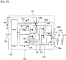
- FIG. 16 is a block diagram illustrating the circuit configuration of the controller 171.
- the controller 171 has the same configuration as that of the controller 149 of FIG. 14 except that a target to be subjected to forward and backward rotational drive is not the washer motor, but the rear wiper motor 117. That is, a rear wiper motor drive part 172 is provided in place of the washer motor drive part 67 of FIG. 16 .
- the FET module 160 is partitioned into the battery reverse connection protection part 165, front wiper motor drive part 166, and a rear wiper motor drive part 172.
- the battery reverse connection protection part 165 is provided with one FET 168a
- the front wiper motor drive part 166 is provided with two FETs 168b and 168c
- the rear wiper motor drive part 172 is provided with four FETs 168d to 168g.
- a bridge circuit for forward and backward rotational drive of the rear wiper motor 117 is formed by the FETs 168d to 168g.
- the general-purpose FET module for three-phase motor drive is diverted to control of the wiper system to constitute the controller 171.
- the controller 171 As a result, it is possible to realize a compact controller capable of controlling both the front wiper motor and the rear wiper motor without involving increase in the size of the drive circuit.
- the present invention is applied to the wiper system of a parallel wiping type rotationally driven forward and backward by one motor (first and third embodiments), the wiper system of an opposing wiping type rotationally driven forward and backward by two motors (second and fourth embodiments), and the wiper system of a parallel wiping type rotationally driven in one direction by one motor (fifth to seventh embodiments) ; however, the present invention may be applied to wiper systems of other embodiments, such as a wiper system of a parallel wiping type rotationally driven forward and backward by two motors. That is, the present invention may be applied to any wiper system as long as seven FETs can be appropriately assigned thereto for drive of, for example, the front wiper motor, rear wiper motor, and washer motor.
- the heat plate can be used for miniaturization of the device in the controllers of the second and subsequent embodiments, as in the first embodiment.
- the washer nozzles are formed on both side surfaces of each wiper blade as illustrated in FIGS. 4 , 5 , and 13 ; however, the present invention is not limited to this.
- the washer nozzles may be formed in the wiper arm or a vehicle body.
- the circuit configuration of the controller according to the sixth embodiment is not limited to that illustrated in FIG. 12 .
- the controller according to the sixth embodiment may employ the configuration of a high-side drive type as illustrated in FIG. 17 .
Applications Claiming Priority (4)
| Application Number | Priority Date | Filing Date | Title |
|---|---|---|---|
| JP2015098798 | 2015-05-14 | ||
| JP2015098797 | 2015-05-14 | ||
| JP2016008006 | 2016-01-19 | ||
| PCT/JP2016/064184 WO2016182031A1 (ja) | 2015-05-14 | 2016-05-12 | ワイパシステム制御装置 |
Publications (3)
| Publication Number | Publication Date |
|---|---|
| EP3296165A1 true EP3296165A1 (de) | 2018-03-21 |
| EP3296165A4 EP3296165A4 (de) | 2019-01-02 |
| EP3296165B1 EP3296165B1 (de) | 2020-12-30 |
Family
ID=57249213
Family Applications (1)
| Application Number | Title | Priority Date | Filing Date |
|---|---|---|---|
| EP16792756.5A Active EP3296165B1 (de) | 2015-05-14 | 2016-05-12 | Vorrichtung zur regelung eines windschutzscheibenwischersystems |
Country Status (4)
| Country | Link |
|---|---|
| US (1) | US20180141520A1 (de) |
| EP (1) | EP3296165B1 (de) |
| JP (1) | JP6412260B2 (de) |
| WO (1) | WO2016182031A1 (de) |
Families Citing this family (3)
| Publication number | Priority date | Publication date | Assignee | Title |
|---|---|---|---|---|
| CN108045345B (zh) * | 2017-12-01 | 2020-11-13 | 中车株洲电力机车有限公司 | 一种轨道车辆洗涤系统及控制方法 |
| KR102060636B1 (ko) * | 2017-12-20 | 2019-12-30 | (주)티에이치엔 | 전력 반도체를 이용한 와이퍼 제어 시스템 및 그 방법 |
| CN111645634B (zh) * | 2019-09-29 | 2022-05-31 | 摩登汽车有限公司 | 智能雨刮及洗涤装置 |
Family Cites Families (18)
| Publication number | Priority date | Publication date | Assignee | Title |
|---|---|---|---|---|
| IT1156372B (it) * | 1982-06-22 | 1987-02-04 | Fiat Auto Spa | Dispositivo di regolazione automatica della frequenza di attivazione di un tergicristallo per veicoli |
| JP2560436Y2 (ja) * | 1989-08-23 | 1998-01-21 | 株式会社東海理化電機製作所 | モータ駆動回路 |
| US6281649B1 (en) * | 1997-01-03 | 2001-08-28 | Mccord Winn Textron Inc. | Windshield wiper system |
| JP3338328B2 (ja) * | 1997-04-21 | 2002-10-28 | 株式会社日立製作所 | 乗物の電力供給装置 |
| US6069461A (en) * | 1998-11-16 | 2000-05-30 | Ford Global Technologies, Inc. | Digital or resistorless interval wiper switch and system |
| JP4005256B2 (ja) * | 1999-03-05 | 2007-11-07 | アスモ株式会社 | ワイパ制御装置 |
| JP3901439B2 (ja) * | 2000-09-19 | 2007-04-04 | 矢崎総業株式会社 | ワイパ制御装置 |
| JP2002178881A (ja) * | 2000-12-12 | 2002-06-26 | Mitsuba Corp | ワイパ装置 |
| JP2002362322A (ja) * | 2001-06-01 | 2002-12-18 | Mitsuba Corp | 車載電装品の制御装置 |
| JP2004194418A (ja) * | 2002-12-11 | 2004-07-08 | Mitsuba Corp | 電動モータの制御装置 |
| JP5014133B2 (ja) * | 2005-07-27 | 2012-08-29 | 株式会社ミツバ | モータ制御方法及びモータ制御システム |
| JP2008189158A (ja) * | 2007-02-05 | 2008-08-21 | Asmo Co Ltd | ワイパ装置及びワイパシステム |
| JP2009090780A (ja) * | 2007-10-05 | 2009-04-30 | Mitsubishi Fuso Truck & Bus Corp | 車両装備品の作動状態検出装置 |
| EP2734418B1 (de) * | 2011-07-22 | 2017-05-31 | Magna International Inc. | Scheibenwischermodul |
| DE102012203335A1 (de) * | 2012-03-02 | 2013-09-05 | Robert Bosch Gmbh | Feststellbremse in einem Fahrzeug |
| JP6294138B2 (ja) * | 2014-04-18 | 2018-03-14 | アスモ株式会社 | ワイパ制御装置 |
| JP6285296B2 (ja) * | 2014-06-30 | 2018-02-28 | アスモ株式会社 | ワイパ装置 |
| JP6379792B2 (ja) * | 2014-07-23 | 2018-08-29 | 株式会社デンソー | ワイパ装置 |
-
2016
- 2016-05-12 EP EP16792756.5A patent/EP3296165B1/de active Active
- 2016-05-12 JP JP2017517988A patent/JP6412260B2/ja not_active Expired - Fee Related
- 2016-05-12 US US15/573,026 patent/US20180141520A1/en not_active Abandoned
- 2016-05-12 WO PCT/JP2016/064184 patent/WO2016182031A1/ja active Application Filing
Also Published As
| Publication number | Publication date |
|---|---|
| JP6412260B2 (ja) | 2018-10-24 |
| EP3296165A4 (de) | 2019-01-02 |
| EP3296165B1 (de) | 2020-12-30 |
| JPWO2016182031A1 (ja) | 2017-12-07 |
| WO2016182031A1 (ja) | 2016-11-17 |
| US20180141520A1 (en) | 2018-05-24 |
Similar Documents
| Publication | Publication Date | Title |
|---|---|---|
| EP3296165B1 (de) | Vorrichtung zur regelung eines windschutzscheibenwischersystems | |
| JP6349120B2 (ja) | ワイパシステム制御方法及びワイパシステム制御装置 | |
| WO1998029285A9 (en) | Windshield wiper system | |
| JP2000255384A (ja) | ワイパ制御装置 | |
| CN105216753A (zh) | 刮水器装置和刮水器电机 | |
| WO2009141245A1 (en) | Windscreen washer module for vehicles and wiper motor for use with a windscreen wiper and washer module | |
| JP3891403B2 (ja) | ワイパ装置の制御方法 | |
| JP4995700B2 (ja) | 対向払拭型ワイパ装置 | |
| JP7098440B2 (ja) | 車両の窓を拭いて洗浄するために制御されるシステム、フロントガラスワイパー、フロントガラスワイパーブレード、および車両への取り付け方法 | |
| US20090119866A1 (en) | Wiper apparatus control method and wiper control system | |
| US20220203936A1 (en) | Vehicle-mounted sensor cleaning device and vehicle-mounted sensor cleaning system | |
| KR100689644B1 (ko) | 윈드스크린 와이퍼 구동 장치 및 그 장치가 장착된 차량 | |
| EP3584124A1 (de) | Wischvorrichtung und fahrzeug damit | |
| WO2016072233A1 (ja) | ワイパシステム | |
| JP6372958B2 (ja) | ワイパシステム | |
| JP6719927B2 (ja) | ワイパシステム | |
| JP2021066236A (ja) | ワイパシステム | |
| JP6510967B2 (ja) | ワイパ制御装置及びワイパ制御装置の制御方法 | |
| KR100229741B1 (ko) | 차량의 수직구동형 와이퍼장치 | |
| JP2023158666A (ja) | ワイパ制御装置 | |
| JPH11301417A (ja) | 対向払拭型ワイパ装置の制御方法 | |
| JP6653278B2 (ja) | ワイパシステム及びワイパシステム制御方法 | |
| JP6802740B2 (ja) | ワイパ制御方法及びワイパ制御装置 | |
| JPH11301414A (ja) | ワイパ装置 | |
| JP2023156089A (ja) | ワイパ制御装置 |
Legal Events
| Date | Code | Title | Description |
|---|---|---|---|
| STAA | Information on the status of an ep patent application or granted ep patent |
Free format text: STATUS: THE INTERNATIONAL PUBLICATION HAS BEEN MADE |
|
| PUAI | Public reference made under article 153(3) epc to a published international application that has entered the european phase |
Free format text: ORIGINAL CODE: 0009012 |
|
| STAA | Information on the status of an ep patent application or granted ep patent |
Free format text: STATUS: REQUEST FOR EXAMINATION WAS MADE |
|
| 17P | Request for examination filed |
Effective date: 20171114 |
|
| AK | Designated contracting states |
Kind code of ref document: A1 Designated state(s): AL AT BE BG CH CY CZ DE DK EE ES FI FR GB GR HR HU IE IS IT LI LT LU LV MC MK MT NL NO PL PT RO RS SE SI SK SM TR |
|
| AX | Request for extension of the european patent |
Extension state: BA ME |
|
| DAV | Request for validation of the european patent (deleted) | ||
| DAX | Request for extension of the european patent (deleted) | ||
| A4 | Supplementary search report drawn up and despatched |
Effective date: 20181130 |
|
| RIC1 | Information provided on ipc code assigned before grant |
Ipc: B60S 1/48 20060101ALN20181126BHEP Ipc: B60S 1/08 20060101AFI20181126BHEP Ipc: B60S 1/46 20060101ALN20181126BHEP |
|
| RIC1 | Information provided on ipc code assigned before grant |
Ipc: B60S 1/08 20060101AFI20200702BHEP Ipc: B60S 1/48 20060101ALN20200702BHEP Ipc: B60S 1/46 20060101ALN20200702BHEP |
|
| GRAP | Despatch of communication of intention to grant a patent |
Free format text: ORIGINAL CODE: EPIDOSNIGR1 |
|
| RIC1 | Information provided on ipc code assigned before grant |
Ipc: B60S 1/46 20060101ALN20200714BHEP Ipc: B60S 1/48 20060101ALN20200714BHEP Ipc: B60S 1/08 20060101AFI20200714BHEP |
|
| STAA | Information on the status of an ep patent application or granted ep patent |
Free format text: STATUS: GRANT OF PATENT IS INTENDED |
|
| INTG | Intention to grant announced |
Effective date: 20200820 |
|
| GRAS | Grant fee paid |
Free format text: ORIGINAL CODE: EPIDOSNIGR3 |
|
| GRAA | (expected) grant |
Free format text: ORIGINAL CODE: 0009210 |
|
| STAA | Information on the status of an ep patent application or granted ep patent |
Free format text: STATUS: THE PATENT HAS BEEN GRANTED |
|
| AK | Designated contracting states |
Kind code of ref document: B1 Designated state(s): AL AT BE BG CH CY CZ DE DK EE ES FI FR GB GR HR HU IE IS IT LI LT LU LV MC MK MT NL NO PL PT RO RS SE SI SK SM TR |
|
| REG | Reference to a national code |
Ref country code: GB Ref legal event code: FG4D |
|
| REG | Reference to a national code |
Ref country code: DE Ref legal event code: R096 Ref document number: 602016050673 Country of ref document: DE |
|
| REG | Reference to a national code |
Ref country code: AT Ref legal event code: REF Ref document number: 1349634 Country of ref document: AT Kind code of ref document: T Effective date: 20210115 |
|
| REG | Reference to a national code |
Ref country code: IE Ref legal event code: FG4D |
|
| PG25 | Lapsed in a contracting state [announced via postgrant information from national office to epo] |
Ref country code: NO Free format text: LAPSE BECAUSE OF FAILURE TO SUBMIT A TRANSLATION OF THE DESCRIPTION OR TO PAY THE FEE WITHIN THE PRESCRIBED TIME-LIMIT Effective date: 20210330 Ref country code: RS Free format text: LAPSE BECAUSE OF FAILURE TO SUBMIT A TRANSLATION OF THE DESCRIPTION OR TO PAY THE FEE WITHIN THE PRESCRIBED TIME-LIMIT Effective date: 20201230 Ref country code: FI Free format text: LAPSE BECAUSE OF FAILURE TO SUBMIT A TRANSLATION OF THE DESCRIPTION OR TO PAY THE FEE WITHIN THE PRESCRIBED TIME-LIMIT Effective date: 20201230 Ref country code: GR Free format text: LAPSE BECAUSE OF FAILURE TO SUBMIT A TRANSLATION OF THE DESCRIPTION OR TO PAY THE FEE WITHIN THE PRESCRIBED TIME-LIMIT Effective date: 20210331 |
|
| REG | Reference to a national code |
Ref country code: AT Ref legal event code: MK05 Ref document number: 1349634 Country of ref document: AT Kind code of ref document: T Effective date: 20201230 |
|
| PG25 | Lapsed in a contracting state [announced via postgrant information from national office to epo] |
Ref country code: SE Free format text: LAPSE BECAUSE OF FAILURE TO SUBMIT A TRANSLATION OF THE DESCRIPTION OR TO PAY THE FEE WITHIN THE PRESCRIBED TIME-LIMIT Effective date: 20201230 Ref country code: BG Free format text: LAPSE BECAUSE OF FAILURE TO SUBMIT A TRANSLATION OF THE DESCRIPTION OR TO PAY THE FEE WITHIN THE PRESCRIBED TIME-LIMIT Effective date: 20210330 Ref country code: LV Free format text: LAPSE BECAUSE OF FAILURE TO SUBMIT A TRANSLATION OF THE DESCRIPTION OR TO PAY THE FEE WITHIN THE PRESCRIBED TIME-LIMIT Effective date: 20201230 |
|
| REG | Reference to a national code |
Ref country code: NL Ref legal event code: MP Effective date: 20201230 |
|
| PG25 | Lapsed in a contracting state [announced via postgrant information from national office to epo] |
Ref country code: HR Free format text: LAPSE BECAUSE OF FAILURE TO SUBMIT A TRANSLATION OF THE DESCRIPTION OR TO PAY THE FEE WITHIN THE PRESCRIBED TIME-LIMIT Effective date: 20201230 |
|
| REG | Reference to a national code |
Ref country code: LT Ref legal event code: MG9D |
|
| PG25 | Lapsed in a contracting state [announced via postgrant information from national office to epo] |
Ref country code: RO Free format text: LAPSE BECAUSE OF FAILURE TO SUBMIT A TRANSLATION OF THE DESCRIPTION OR TO PAY THE FEE WITHIN THE PRESCRIBED TIME-LIMIT Effective date: 20201230 Ref country code: SK Free format text: LAPSE BECAUSE OF FAILURE TO SUBMIT A TRANSLATION OF THE DESCRIPTION OR TO PAY THE FEE WITHIN THE PRESCRIBED TIME-LIMIT Effective date: 20201230 Ref country code: PT Free format text: LAPSE BECAUSE OF FAILURE TO SUBMIT A TRANSLATION OF THE DESCRIPTION OR TO PAY THE FEE WITHIN THE PRESCRIBED TIME-LIMIT Effective date: 20210430 Ref country code: LT Free format text: LAPSE BECAUSE OF FAILURE TO SUBMIT A TRANSLATION OF THE DESCRIPTION OR TO PAY THE FEE WITHIN THE PRESCRIBED TIME-LIMIT Effective date: 20201230 Ref country code: CZ Free format text: LAPSE BECAUSE OF FAILURE TO SUBMIT A TRANSLATION OF THE DESCRIPTION OR TO PAY THE FEE WITHIN THE PRESCRIBED TIME-LIMIT Effective date: 20201230 Ref country code: EE Free format text: LAPSE BECAUSE OF FAILURE TO SUBMIT A TRANSLATION OF THE DESCRIPTION OR TO PAY THE FEE WITHIN THE PRESCRIBED TIME-LIMIT Effective date: 20201230 |
|
| PGFP | Annual fee paid to national office [announced via postgrant information from national office to epo] |
Ref country code: DE Payment date: 20210413 Year of fee payment: 6 Ref country code: FR Payment date: 20210412 Year of fee payment: 6 |
|
| PG25 | Lapsed in a contracting state [announced via postgrant information from national office to epo] |
Ref country code: AT Free format text: LAPSE BECAUSE OF FAILURE TO SUBMIT A TRANSLATION OF THE DESCRIPTION OR TO PAY THE FEE WITHIN THE PRESCRIBED TIME-LIMIT Effective date: 20201230 Ref country code: PL Free format text: LAPSE BECAUSE OF FAILURE TO SUBMIT A TRANSLATION OF THE DESCRIPTION OR TO PAY THE FEE WITHIN THE PRESCRIBED TIME-LIMIT Effective date: 20201230 |
|
| PG25 | Lapsed in a contracting state [announced via postgrant information from national office to epo] |
Ref country code: IS Free format text: LAPSE BECAUSE OF FAILURE TO SUBMIT A TRANSLATION OF THE DESCRIPTION OR TO PAY THE FEE WITHIN THE PRESCRIBED TIME-LIMIT Effective date: 20210430 |
|
| REG | Reference to a national code |
Ref country code: DE Ref legal event code: R097 Ref document number: 602016050673 Country of ref document: DE |
|
| PG25 | Lapsed in a contracting state [announced via postgrant information from national office to epo] |
Ref country code: AL Free format text: LAPSE BECAUSE OF FAILURE TO SUBMIT A TRANSLATION OF THE DESCRIPTION OR TO PAY THE FEE WITHIN THE PRESCRIBED TIME-LIMIT Effective date: 20201230 Ref country code: IT Free format text: LAPSE BECAUSE OF FAILURE TO SUBMIT A TRANSLATION OF THE DESCRIPTION OR TO PAY THE FEE WITHIN THE PRESCRIBED TIME-LIMIT Effective date: 20201230 |
|
| PLBE | No opposition filed within time limit |
Free format text: ORIGINAL CODE: 0009261 |
|
| STAA | Information on the status of an ep patent application or granted ep patent |
Free format text: STATUS: NO OPPOSITION FILED WITHIN TIME LIMIT |
|
| PG25 | Lapsed in a contracting state [announced via postgrant information from national office to epo] |
Ref country code: DK Free format text: LAPSE BECAUSE OF FAILURE TO SUBMIT A TRANSLATION OF THE DESCRIPTION OR TO PAY THE FEE WITHIN THE PRESCRIBED TIME-LIMIT Effective date: 20201230 |
|
| 26N | No opposition filed |
Effective date: 20211001 |
|
| REG | Reference to a national code |
Ref country code: CH Ref legal event code: PL |
|
| GBPC | Gb: european patent ceased through non-payment of renewal fee |
Effective date: 20210512 |
|
| PG25 | Lapsed in a contracting state [announced via postgrant information from national office to epo] |
Ref country code: CH Free format text: LAPSE BECAUSE OF NON-PAYMENT OF DUE FEES Effective date: 20210531 Ref country code: LI Free format text: LAPSE BECAUSE OF NON-PAYMENT OF DUE FEES Effective date: 20210531 Ref country code: MC Free format text: LAPSE BECAUSE OF FAILURE TO SUBMIT A TRANSLATION OF THE DESCRIPTION OR TO PAY THE FEE WITHIN THE PRESCRIBED TIME-LIMIT Effective date: 20201230 Ref country code: LU Free format text: LAPSE BECAUSE OF NON-PAYMENT OF DUE FEES Effective date: 20210512 Ref country code: ES Free format text: LAPSE BECAUSE OF FAILURE TO SUBMIT A TRANSLATION OF THE DESCRIPTION OR TO PAY THE FEE WITHIN THE PRESCRIBED TIME-LIMIT Effective date: 20201230 |
|
| REG | Reference to a national code |
Ref country code: BE Ref legal event code: MM Effective date: 20210531 |
|
| PG25 | Lapsed in a contracting state [announced via postgrant information from national office to epo] |
Ref country code: SI Free format text: LAPSE BECAUSE OF FAILURE TO SUBMIT A TRANSLATION OF THE DESCRIPTION OR TO PAY THE FEE WITHIN THE PRESCRIBED TIME-LIMIT Effective date: 20201230 |
|
| PG25 | Lapsed in a contracting state [announced via postgrant information from national office to epo] |
Ref country code: IE Free format text: LAPSE BECAUSE OF NON-PAYMENT OF DUE FEES Effective date: 20210512 Ref country code: GB Free format text: LAPSE BECAUSE OF NON-PAYMENT OF DUE FEES Effective date: 20210512 |
|
| PG25 | Lapsed in a contracting state [announced via postgrant information from national office to epo] |
Ref country code: IS Free format text: LAPSE BECAUSE OF FAILURE TO SUBMIT A TRANSLATION OF THE DESCRIPTION OR TO PAY THE FEE WITHIN THE PRESCRIBED TIME-LIMIT Effective date: 20210430 |
|
| PG25 | Lapsed in a contracting state [announced via postgrant information from national office to epo] |
Ref country code: BE Free format text: LAPSE BECAUSE OF NON-PAYMENT OF DUE FEES Effective date: 20210531 |
|
| REG | Reference to a national code |
Ref country code: DE Ref legal event code: R119 Ref document number: 602016050673 Country of ref document: DE |
|
| PG25 | Lapsed in a contracting state [announced via postgrant information from national office to epo] |
Ref country code: FR Free format text: LAPSE BECAUSE OF NON-PAYMENT OF DUE FEES Effective date: 20220531 |
|
| PG25 | Lapsed in a contracting state [announced via postgrant information from national office to epo] |
Ref country code: HU Free format text: LAPSE BECAUSE OF FAILURE TO SUBMIT A TRANSLATION OF THE DESCRIPTION OR TO PAY THE FEE WITHIN THE PRESCRIBED TIME-LIMIT; INVALID AB INITIO Effective date: 20160512 Ref country code: DE Free format text: LAPSE BECAUSE OF NON-PAYMENT OF DUE FEES Effective date: 20221201 |
|
| PG25 | Lapsed in a contracting state [announced via postgrant information from national office to epo] |
Ref country code: NL Free format text: LAPSE BECAUSE OF NON-PAYMENT OF DUE FEES Effective date: 20201230 Ref country code: CY Free format text: LAPSE BECAUSE OF FAILURE TO SUBMIT A TRANSLATION OF THE DESCRIPTION OR TO PAY THE FEE WITHIN THE PRESCRIBED TIME-LIMIT Effective date: 20201230 |
|
| PG25 | Lapsed in a contracting state [announced via postgrant information from national office to epo] |
Ref country code: SM Free format text: LAPSE BECAUSE OF FAILURE TO SUBMIT A TRANSLATION OF THE DESCRIPTION OR TO PAY THE FEE WITHIN THE PRESCRIBED TIME-LIMIT Effective date: 20201230 |
|
| PG25 | Lapsed in a contracting state [announced via postgrant information from national office to epo] |
Ref country code: MK Free format text: LAPSE BECAUSE OF FAILURE TO SUBMIT A TRANSLATION OF THE DESCRIPTION OR TO PAY THE FEE WITHIN THE PRESCRIBED TIME-LIMIT Effective date: 20201230 |