EP3293307B1 - Vorrichtung zur verstellung einer abstreifleiste in einer anlage zur erzeugung eines papierbandes - Google Patents
Vorrichtung zur verstellung einer abstreifleiste in einer anlage zur erzeugung eines papierbandes Download PDFInfo
- Publication number
- EP3293307B1 EP3293307B1 EP17187440.7A EP17187440A EP3293307B1 EP 3293307 B1 EP3293307 B1 EP 3293307B1 EP 17187440 A EP17187440 A EP 17187440A EP 3293307 B1 EP3293307 B1 EP 3293307B1
- Authority
- EP
- European Patent Office
- Prior art keywords
- bar
- scraper
- support
- support bar
- scraper bar
- Prior art date
- Legal status (The legal status is an assumption and is not a legal conclusion. Google has not performed a legal analysis and makes no representation as to the accuracy of the status listed.)
- Active
Links
Images


Classifications
-
- D—TEXTILES; PAPER
- D21—PAPER-MAKING; PRODUCTION OF CELLULOSE
- D21G—CALENDERS; ACCESSORIES FOR PAPER-MAKING MACHINES
- D21G3/00—Doctors
-
- D—TEXTILES; PAPER
- D21—PAPER-MAKING; PRODUCTION OF CELLULOSE
- D21F—PAPER-MAKING MACHINES; METHODS OF PRODUCING PAPER THEREON
- D21F1/00—Wet end of machines for making continuous webs of paper
-
- D—TEXTILES; PAPER
- D21—PAPER-MAKING; PRODUCTION OF CELLULOSE
- D21F—PAPER-MAKING MACHINES; METHODS OF PRODUCING PAPER THEREON
- D21F1/00—Wet end of machines for making continuous webs of paper
- D21F1/24—Tilting, raising, or lowering mechanisms for wire-cloths
-
- D—TEXTILES; PAPER
- D21—PAPER-MAKING; PRODUCTION OF CELLULOSE
- D21F—PAPER-MAKING MACHINES; METHODS OF PRODUCING PAPER THEREON
- D21F1/00—Wet end of machines for making continuous webs of paper
- D21F1/48—Suction apparatus
-
- D—TEXTILES; PAPER
- D21—PAPER-MAKING; PRODUCTION OF CELLULOSE
- D21F—PAPER-MAKING MACHINES; METHODS OF PRODUCING PAPER THEREON
- D21F1/00—Wet end of machines for making continuous webs of paper
- D21F1/48—Suction apparatus
- D21F1/483—Drainage foils and bars
-
- D—TEXTILES; PAPER
- D21—PAPER-MAKING; PRODUCTION OF CELLULOSE
- D21F—PAPER-MAKING MACHINES; METHODS OF PRODUCING PAPER THEREON
- D21F1/00—Wet end of machines for making continuous webs of paper
- D21F1/48—Suction apparatus
- D21F1/483—Drainage foils and bars
- D21F1/486—Drainage foils and bars adjustable
-
- D—TEXTILES; PAPER
- D21—PAPER-MAKING; PRODUCTION OF CELLULOSE
- D21F—PAPER-MAKING MACHINES; METHODS OF PRODUCING PAPER THEREON
- D21F1/00—Wet end of machines for making continuous webs of paper
- D21F1/48—Suction apparatus
- D21F1/52—Suction boxes without rolls
- D21F1/523—Covers thereof
Definitions
- the present invention relates to an adjusting device with the features of the preamble of claim 1.
- Known systems for producing a paper belt have a self-contained, rotating screen belt onto which a mixture of materials is applied at the beginning of the system to produce the paper belt.
- a mixture of materials is applied at the beginning of the system to produce the paper belt.
- there are scraper strips underneath the screen belt that extend across the screen belt and are spaced apart from each other in the direction of movement of the screen belt.
- suction boxes are arranged underneath the screen belt through which the liquid that has escaped from the mixture of materials is sucked out.
- felt belts and drying rollers are also provided after the screen belt, through which the paper belt is dried.
- the scraper bars When the scraper bars are in contact with the underside of the screen belt, the liquid that has passed through the screen belt is scraped off. Furthermore, when the surface of the scraper bars forms an acute angle with the screen belt, which angle opens in the direction of movement of the screen belt, the scraper bars exert a suction force on the screen belt or on the liquid that has escaped from the mixture of materials. Since the scraping effect and the suction force exerted by a scraper bar depend on the height and angle of the scraper bar in relation to the screen belt, it is necessary to provide an adjusting device by means of which the height and angle of the scraper bar can be adjusted in relation to the support bar for the scraper bar, whereby the height and angle of the scraper bar in relation to the screen belt can be adjusted.
- control blocks between a support bar for the scraper bar and the scraper bar which can be moved in the longitudinal direction of the support bar or the scraper bar by means of an adjusting spindle.
- the control blocks and the scraper bar are designed with guide rails, by means of which the height or angle of the scraper bar can be adjusted relative to the support bar and thus relative to the screen belt when the control blocks are moved.
- this known device has the problem that the liquid that comes out of the mixture contains components of the mixture that get into the guide rail, making it difficult to move, which is why very high actuating forces have to be applied by the adjusting spindle to move the control blocks relative to the scraper bar. For this reason, the adjusting spindle has to be large and the guide rail has to be cleaned more frequently.
- the object of the present invention is to avoid these disadvantages inherent in the known prior art. This is achieved according to the invention by an adjustment device with the features of claim 1.
- the adjusting device is formed by a pivotable angle lever mounted on the support bar and an adjusting rod hinged on the one hand to the angle lever and on the other hand to the scraper bar, whereby the scraper bar can be moved parallel to the support bar by pivoting the angle lever.
- the adjusting rod can be adjustable in its effective length.
- an adjusting cylinder can be arranged on the angle lever and can be pivoted with it, which is mounted so that it can rotate relative to the angle lever.
- the rotatable actuating cylinder is designed with a spiral groove on its side facing the angle lever and an arcuately curved actuating plate with teeth is attached to the support bar, which works together with the spiral groove in such a way that the angle lever can be pivoted by rotating the actuating cylinder.
- the angle lever can be pivoted between two stops.
- the actuating cylinder can be rotated by means of a crank.
- support plates are also attached to the scraper bar and the support bar, on which guide elements are mounted, the pivot pins of which are aligned transversely to the longitudinal direction of the scraper bar or the sliding direction.
- the guide elements can be H-shaped, with two longitudinal struts spaced apart from one another and a cross strut connecting them, with the pivot pins passing through the free ends of the longitudinal struts.
- a support plate is attached to the support bar, on which one end of two guide elements are mounted, the pivot axes of these guide elements forming an acute angle of 1° to 10°, preferably of about 5°, with each other, and the other ends of the guide elements being mounted on support elements which are mounted on a support plate attached to the scraper bar, and the pivot axes of the guide elements mounted on the support elements and the pivot axes of the support elements which are mounted on the support plate attached to the scraper bar spatially intersecting each other.
- the two link elements in their initial position can have different angular positions to a vertical plane of e.g. 19.1° and 33.5°, which increase to angular positions of e.g. 33.7° and 51.5° to the vertical plane when the scraper bar is displaced relative to the support bar.
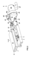
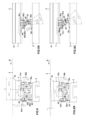
- FIG.1 a scraper bar 1, a support bar 2 associated with it and a screen belt 3 located above the scraper bar 1 are shown in a system for producing a paper belt.
- the screen belt 3 is moved over a wear layer 11 located on the scraper bar 1.
- the scraper bar 1 is designed with a scraper edge 12, through which liquid, which emerges from a mixture of substances located on the screen belt 3 for producing the paper belt and reaches the underside of the screen belt 3, is scraped off the screen belt 3.
- the scraper bar 1 is coupled to the support bar 2 by means of links 4 and 5, respectively, which are pivotably mounted on the scraper bar 1 and the support bar 2. Furthermore, an adjusting device 6 is provided, by means of which the scraper bar 1 can be moved parallel to the support bar 2. By moving the scraper bar 1 relative to the support bar 2, the distance of the scraper bar 1 relative to the support bar 2 is changed by the links 4 of a first embodiment. By moving the scraper bar 1 relative to the support bar 2, the angular position is changed by the links 5 of a second embodiment. the scraper bar 1 relative to the support bar 2 or relative to the screen belt 3.
- the scraper bars By adjusting the height of the scraper bars, their scraping effect can be controlled and the height of the screen belt and thus its path can be influenced. Furthermore, the scraper bars can be adjusted to a non-effective position.
- the angle that forms between the screen belt and the surface of the scraper bars in the direction of movement of the screen belt after the front scraper edge of the scraper bars can be adjusted in its size and thus in its suction effect.
- the adjusting device 6 is designed with an angle lever 61, which is mounted by means of a pivot pin 62 between two support plates 63 located at a distance from one another.
- the support plates 63 are fastened to the support bar 2.
- an adjusting rod 64 is provided, the length of which is adjustable, which is hinged at one end to the associated end of the angle lever 61 and at the other end to the scraper bar 1.
- a retaining ring 65 is attached to the angle lever 61, through which an adjusting cylinder 66 is connected to the angle lever 61 in such a way that it can be pivoted with it, but it can be rotated relative to the angle lever 61.
- the rotation of the adjusting cylinder 66 takes place by means of a crank 67.
- an adjusting plate 68 is attached to the support plates 63, which is curved in an arc shape at its edge associated with the adjusting cylinder 66 and is formed with teeth 68a along the edge.
- the adjusting plate 68 interacts with the actuating cylinder 66 in such a way that when the actuating cylinder 66 is rotated, the angle lever 61 is pivoted.
- the pivoting movement is limited by two stops 69.
- FIG.1 the position of the links 4, 5 is shown in which the scraper bar 1 has not been adjusted and it is in full contact with the underside of the screen belt 3.
- FIG.1A the position of the links 4, 5 is shown in which the scraper bar 1 was adjusted, whereby it was adjusted either in its distance or in its angular position relative to the support bar 2.
- the adjusting rod 64 consists of two bolts 64a and 64b, which are screwed into a threaded sleeve 64c, whereby the threads of the bolts 64a and 64b and of the threaded sleeve 64c are designed in such a way that the adjusting rod 64 is lengthened or shortened by turning the threaded sleeve 64c. This causes a pre-setting of the position of the scraper strip 1 relative to the support strip 2.
- the actuating cylinder 66 is formed on its side facing the angle lever 61 with a spiral groove 66a into which teeth 68a of the actuating plate 68 protrude.
- the actuating plate 68 which is located between two spaced-apart plates of the angle lever 61, is rigidly attached to the support plates 63 and thus to the support bar 2.
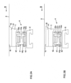
- a link 4 of the first embodiment by means of which the distance between the scraper strip 1 and the support strip 2 can be adjusted, is designed with an H-shaped link element 41 which has two longitudinal struts 41a, 41b and a cross strut 41c connecting them.
- a support plate 42 is fastened to the scraper strip 1 and a support plate 43 is fastened to the support strip 2.
- the two support plates 42, 43 are designed with transversely projecting tabs in which there are holes in which the link element 41 is mounted by means of pivot pins 42a, 43a.
- FIG.3A the screen belt 3 rests against the surface 13 of the scraper bar 1.
- FIG.3B the distance between the scraper bar 1 and the support bar 2 has been reduced, whereby the scraper bar 1 is adjusted downwards away from the screen belt 3.
- the length of the support bars and the scraper bars can be up to 11 m.
- the width of the support bars and the scraper bars can be 35 mm to 80 mm.
- the length of the handlebars can be about 15 mm.
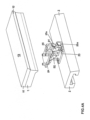
- FIG.4 and FIG.4A a guide 5 of the second embodiment is shown, which serves to change the angular position of the scraper bar 1 relative to the support bar 2 or relative to the screen belt 3 by moving the scraper bar 1 relative to the support bar 2.
- This can cause the front scraper edge 12 of the scraper bar 1 in the direction of movement B of the screen belt 3 to rest on the underside of the screen belt 3 and the surface 13 of the scraper bar 1 to form an acute angle with the screen belt 3.
- a negative pressure is generated on the underside of the sieve belt 3, by means of which a suction force is exerted on the sieve belt 3 or on the liquid which emerges from the mixture of substances located on the sieve belt 3.
- the link 5 has two link elements 51 and 52, which are mounted on a support plate 53, which is attached to the support bar 2, by means of pivot pins 53a, 53b.
- the support plate 53 is designed with transversely projecting tabs, which are provided with holes into which the pivot pins 53a, 53b are inserted.
- the pivot axes 53c, 53d of the two link elements 51, 52 form an acute angle of e.g. 5.5° with one another.
- a support plate 54 is attached to the scraper bar 1, in which U-shaped support elements 55, 56 are pivotably mounted by means of pivot pins 54a, 54b, with their pivot axes 54c, 54d being aligned parallel to one another.
- the other ends of the link elements 51, 52 are mounted in the U-shaped support elements 55, 56 by means of pivot pins 55a, 56a, whereby the pivot axes 55b, 56b also form an acute angle of e.g. 5.5° with each other.
- the pivot axes 53c, 55b and 53d, 56b are aligned parallel to each other.
- the pivot axes 54c and 55b as well as the pivot axes 54d and 56b cross each other spatially at an angle of approximately 90°.
- the guide element 51 can be pivoted about the pivot axes 53c and 55b and the support element 55 assigned to it can be pivoted relative to the support plate 54 about the pivot axis 54c.
- the guide element 52 can also be pivoted about the pivot axes 53d and 56b and the support element 56 assigned to it can be pivoted relative to the support plate 54 about the pivot axis 54d. Due to these multiple bearings, the guide elements 51 and 52 can be pivoted in different ways. In the initial position, the guide elements 51 and 52 form acute angles with the vertical plane, with the guide element 51 being inclined somewhat less than the guide element 52. By moving the scraper bar 1 relative to the support bar 2, its angular position relative to the support bar 2 or relative to the screen belt 3 is changed.
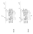
- the guide elements 51 and 52 are pivoted further relative to the vertical plane, whereby the scraper bar 1 is adjusted downwards via the guide elements 51 and 52 and the support elements 55 and 56. Since the pivot axes of the two guide elements 51 and 52 form an acute angle with one another, the support element 56 is adjusted downwards more by the guide element 52 than by the guide element 51 of the support element 55, whereby the support plate 54 and with it the scraper bar 1 are pivoted clockwise about the pivot pins 54a, 54b. This pivots the scraper bar 1 relative to the support bar 2.
- the pivoting of the scraper bar 1 can be controlled such that its scraper edge 12 remains on the underside of the screen belt 3.
- FIG.4B the position of the scraper bar 1 is shown in which its surface 13 is in full contact with the underside of the screen belt 3.
- the scraper bar 1 has been adjusted in its angular position relative to the support bar 2 or the screen belt 3 due to the adjustment movement caused by the guide elements 51, 52, the support elements 55 and 56 and the support plate 54, whereby the scraper edge 12 of the scraper bar 1 remains on the underside of the screen belt 3, its surface 13 forms an acute angle of e.g. 3° with the screen belt 3.
- FIG.4C This position of the scraper bar 1 is shown in FIG.4C shown.
- FIG.5 to FIG.5C as well as FIG.6 to FIG.6C an embodiment is shown.
- the normal planes to the pivot axes 53c, 55b of the steering element 51 and to the pivot axes 53d, 56b of the steering element 52 form an angle of 5.5° with each other and the pivot axis 55b of the pivot pin 55a forms an angle of 5.5° with the support plate 54.
- the center plane of the steering element 51 forms an angle of 19.1° with the vertical plane and the center plane of the The link element 52 forms an angle of 33.5° with the vertical plane.
- the pivoting of the scraper bar 1 is explained. If the scraper bar 1 is moved by 3.5 mm relative to the support bar 2, the angular positions of the guide elements 51 and 52 are increased such that the center plane of the guide element 51 forms an angle of 33.7° with the vertical plane and the center plane of the guide element 52 forms an angle of 51.4° with the vertical plane. Due to this adjustment movement, the scraper bar 1 is pivoted such that its surface 13 forms an angle of 3° with the screen belt 3. This increases the angle that the pivot axis 55b forms with the support plate 54 to 8.5°.
- the normal planes on the pivot axes of the handlebar element 51 and the handlebar element 52 remain at an angle of 5.5°.
- the scraper strip 1 has a width of 65 mm and the guide elements 51 and 52 each have a length of 15.5 mm.
- the average distance between the two guide elements is 28.25 mm.
- the pivot axis 54c is located at a distance of 33.52 mm from the scraper edge 12 and at a height distance of 27.77 mm and the pivot axis 54d is located at a longitudinal distance of 63.12 mm from the scraper edge 12 and at a height distance of 30.5 mm.
- the invention is based on the fact that in a papermaking plant, due to the coupling of a scraper bar to a support bar by means of pivotable guide elements and pivotable support elements, the height or angular position of the scraper bar relative to the support bar and thus relative to the screen belt can be changed by moving the scraper bar relative to a support bar.
Landscapes
- Paper (AREA)
- Preliminary Treatment Of Fibers (AREA)
Applications Claiming Priority (1)
| Application Number | Priority Date | Filing Date | Title |
|---|---|---|---|
| ATA404/2016A AT519054B1 (de) | 2016-09-01 | 2016-09-01 | Vorrichtung zur Verstellung einer Abstreifleiste in einer Anlage zur Erzeugung eines Papierbandes |
Publications (2)
| Publication Number | Publication Date |
|---|---|
| EP3293307A1 EP3293307A1 (de) | 2018-03-14 |
| EP3293307B1 true EP3293307B1 (de) | 2024-10-23 |
Family
ID=59686849
Family Applications (1)
| Application Number | Title | Priority Date | Filing Date |
|---|---|---|---|
| EP17187440.7A Active EP3293307B1 (de) | 2016-09-01 | 2017-08-23 | Vorrichtung zur verstellung einer abstreifleiste in einer anlage zur erzeugung eines papierbandes |
Country Status (12)
| Country | Link |
|---|---|
| US (1) | US10273630B2 (pl) |
| EP (1) | EP3293307B1 (pl) |
| JP (1) | JP6751060B2 (pl) |
| CN (1) | CN107794803B (pl) |
| AT (1) | AT519054B1 (pl) |
| BR (1) | BR102017016119B1 (pl) |
| CA (1) | CA2975869C (pl) |
| ES (1) | ES2996657T3 (pl) |
| FI (1) | FI3293307T3 (pl) |
| PL (1) | PL3293307T3 (pl) |
| RU (1) | RU2693747C2 (pl) |
| TW (1) | TWI690638B (pl) |
Citations (1)
| Publication number | Priority date | Publication date | Assignee | Title |
|---|---|---|---|---|
| DE7423054U (de) * | 1973-08-15 | 1976-05-13 | A. Ahlstroem Oy, Noormarkku (Finnland) | Entwaesserungsvorrichtung fuer papiermaschinen |
Family Cites Families (18)
| Publication number | Priority date | Publication date | Assignee | Title |
|---|---|---|---|---|
| DE2510492A1 (de) * | 1975-03-11 | 1976-09-23 | Dieter Rauchmaul Kunststoffver | Siebsaugkasten fuer die papierindustrie |
| CN85104451A (zh) * | 1985-06-11 | 1986-12-10 | 美商贝洛特公司 | 正压锁紧案板刀口 |
| US5169500A (en) * | 1991-10-15 | 1992-12-08 | Wilbanks International | Adjustable angle foil for paper making machine with rigid foil body and cam actuation means |
| DE4306503C2 (de) * | 1993-03-03 | 1994-12-15 | Voith Gmbh J M | Winkeleinstellbare Foil-Entwässerungsleiste für Papiermaschinen |
| AT400158B (de) * | 1993-12-21 | 1995-10-25 | Bartelmuss Klaus Ing | Vorrichtung zur einstellung der höhenlage und bzw. oder der winkellage einer dem siebband einer anlage zur papiererzeugung zugeordneten leiste |
| FI100811B (fi) * | 1997-02-26 | 1998-02-27 | Valmet Corp | Paperikoneen vedenpoistolaitteen lista |
| KR100540065B1 (ko) * | 1999-11-17 | 2006-01-10 | 아스텐죤슨 인코포레이티드 | 쌍 성형직물 제지기의 성형부의 블레이드용 가요성 장착 장치 |
| IT1320857B1 (it) * | 2000-12-12 | 2003-12-10 | Pmt Italia Spa | Gruppo controlama per una macchina per la fabbricazione della carta. |
| US6372093B1 (en) * | 2001-04-26 | 2002-04-16 | Wilbanks International, Inc. | Adjustable foil apparatus for papermaking machine |
| ATE286554T1 (de) * | 2002-01-24 | 2005-01-15 | Heinz Bartelmuss | Einrichtung zur einstellung der lage einer abstreifleiste |
| US6712941B2 (en) * | 2002-04-02 | 2004-03-30 | Weavexx Corporation | Forming board for papermaking machine with adjustable blades |
| AT500283B8 (de) * | 2004-03-17 | 2007-02-15 | Bartelmuss Klaus Ing | Siebleiste für papiererzeugungsanlagen |
| FI20051086A7 (fi) * | 2005-10-27 | 2007-04-28 | Upm Kymmene Corp | Menetelmä ja laitteisto veden poistamiseksi huovasta |
| FI20075177A7 (fi) * | 2007-03-14 | 2008-09-15 | Metso Paper Inc | Vedenpoistoelementti ja metallilistan käyttö vedenpoistoelementissä |
| US8006588B2 (en) * | 2009-01-07 | 2011-08-30 | GM Global Technology Operations LLC | Multi-link parking brake actuation system |
| FI121797B (fi) * | 2009-09-24 | 2011-04-15 | Metso Paper Inc | Vedenpoistoelementti kuiturainakonetta varten |
| US8551293B2 (en) * | 2011-04-21 | 2013-10-08 | Ibs Corp. | Method and machine for manufacturing paper products using Fourdrinier forming |
| US9045859B2 (en) | 2013-02-04 | 2015-06-02 | Ibs Of America | Adjustment mechanism |
-
2016
- 2016-09-01 AT ATA404/2016A patent/AT519054B1/de active
-
2017
- 2017-07-26 TW TW106125141A patent/TWI690638B/zh active
- 2017-07-27 BR BR102017016119-6A patent/BR102017016119B1/pt active IP Right Grant
- 2017-08-11 CA CA2975869A patent/CA2975869C/en active Active
- 2017-08-23 PL PL17187440.7T patent/PL3293307T3/pl unknown
- 2017-08-23 ES ES17187440T patent/ES2996657T3/es active Active
- 2017-08-23 FI FIEP17187440.7T patent/FI3293307T3/fi active
- 2017-08-23 US US15/684,523 patent/US10273630B2/en active Active
- 2017-08-23 EP EP17187440.7A patent/EP3293307B1/de active Active
- 2017-08-28 JP JP2017163460A patent/JP6751060B2/ja active Active
- 2017-08-31 RU RU2017130741A patent/RU2693747C2/ru active
- 2017-08-31 CN CN201710772708.2A patent/CN107794803B/zh active Active
Patent Citations (1)
| Publication number | Priority date | Publication date | Assignee | Title |
|---|---|---|---|---|
| DE7423054U (de) * | 1973-08-15 | 1976-05-13 | A. Ahlstroem Oy, Noormarkku (Finnland) | Entwaesserungsvorrichtung fuer papiermaschinen |
Also Published As
| Publication number | Publication date |
|---|---|
| RU2017130741A (ru) | 2019-02-28 |
| RU2693747C2 (ru) | 2019-07-04 |
| FI3293307T3 (fi) | 2025-01-10 |
| BR102017016119A2 (pt) | 2018-03-20 |
| ES2996657T3 (en) | 2025-02-13 |
| PL3293307T3 (pl) | 2025-03-03 |
| US10273630B2 (en) | 2019-04-30 |
| JP2018035491A (ja) | 2018-03-08 |
| JP6751060B2 (ja) | 2020-09-02 |
| AT519054A1 (de) | 2018-03-15 |
| RU2017130741A3 (pl) | 2019-05-24 |
| US20180058004A1 (en) | 2018-03-01 |
| EP3293307A1 (de) | 2018-03-14 |
| CN107794803B (zh) | 2021-05-18 |
| AT519054B1 (de) | 2018-07-15 |
| TW201812138A (zh) | 2018-04-01 |
| BR102017016119B1 (pt) | 2022-11-22 |
| CA2975869A1 (en) | 2018-03-01 |
| CN107794803A (zh) | 2018-03-13 |
| TWI690638B (zh) | 2020-04-11 |
| CA2975869C (en) | 2021-10-19 |
| BR102017016119A8 (pt) | 2022-08-23 |
Similar Documents
| Publication | Publication Date | Title |
|---|---|---|
| DE2803386C2 (pl) | ||
| DE102008021484B4 (de) | Knickbares Transportband für eine Baumaschine, selbstfahrende Baumaschine und Verfahren zum Verschwenken eines Transportbandes | |
| DE102014016630B4 (de) | Verstelleinrichtung für eine Druckrolle einer Bearbeitungsmaschine, insbesondere Kehlmaschine, sowie Bearbeitsmaschine, insbesondere Kehlmaschine, mit einer solchen Verstelleinrichtung | |
| DE3217381A1 (de) | Vorrichtung zum beschicken von wanderrosten mit gruenpellets | |
| AT394867B (de) | Vorrichtung zur behandlung einer fasersuspension | |
| DE4440944C2 (de) | Vorrichtung zur Einstellung der Höhenlage und bzw. oder der Winkellage einer dem Siebband einer Anlage zur Papiererzeugung zugeordneten Leiste | |
| DE3705195C2 (pl) | ||
| DE19608195C1 (de) | Schälmaschine | |
| EP0013548B1 (de) | Vorrichtung zum Entwässern von wasserhaltigen Stoffen | |
| DE3719305C1 (de) | Schutzvorrichtung fuer den Einlaufspalt von Kalandern und anderen Walzenmaschinen | |
| EP1355002B1 (de) | Einrichtung zur Einstellung der Lage einer Abstreifleiste | |
| EP3293307B1 (de) | Vorrichtung zur verstellung einer abstreifleiste in einer anlage zur erzeugung eines papierbandes | |
| AT502824A4 (de) | Einrichtung zur lösbaren befestigung eines in einer anlage zur papiererzeugung befindlichen halters für eine schaberklinge | |
| DE3900414C2 (pl) | ||
| EP0306719A1 (de) | Vorrichtung zum Abschaben fester Stoffe von einem Transportband | |
| EP1947239A2 (de) | Einrichtung zur lösbaren Befestigung eines Halters für eine Schaberklinge in einer Papiererzeugungsanlage | |
| DE3136793C2 (pl) | ||
| DE9411121U1 (de) | Greiferzylinder in einem Falzapparat | |
| DE4318213C2 (de) | Einrichtung zur Einstellung der Walzenabstände in einer Walzeneinheit | |
| EP2695533B1 (de) | Maschine zur Herstellung von stabförmigen Produkten der Tabak verarbeitenden Industrie | |
| DE10218778A1 (de) | Schaber für die Walzen einer Walzenmühle | |
| DE3137573A1 (de) | Ablenk- und umkehrvorrichtung fuer streifenfoermiges bahnmaterial | |
| DE3923857C2 (de) | Vorrichtung zum Abschneiden von Runddraht oder dergleichen | |
| EP3874092B1 (de) | Breitstreckwalze | |
| EP1155843A2 (de) | Vorrichtung zum Einstellen einer Auftragwalze am Plattenzylinder einer Druckmaschine |
Legal Events
| Date | Code | Title | Description |
|---|---|---|---|
| PUAI | Public reference made under article 153(3) epc to a published international application that has entered the european phase |
Free format text: ORIGINAL CODE: 0009012 |
|
| STAA | Information on the status of an ep patent application or granted ep patent |
Free format text: STATUS: THE APPLICATION HAS BEEN PUBLISHED |
|
| AK | Designated contracting states |
Kind code of ref document: A1 Designated state(s): AL AT BE BG CH CY CZ DE DK EE ES FI FR GB GR HR HU IE IS IT LI LT LU LV MC MK MT NL NO PL PT RO RS SE SI SK SM TR |
|
| AX | Request for extension of the european patent |
Extension state: BA ME |
|
| STAA | Information on the status of an ep patent application or granted ep patent |
Free format text: STATUS: REQUEST FOR EXAMINATION WAS MADE |
|
| 17P | Request for examination filed |
Effective date: 20180914 |
|
| RBV | Designated contracting states (corrected) |
Designated state(s): AL AT BE BG CH CY CZ DE DK EE ES FI FR GB GR HR HU IE IS IT LI LT LU LV MC MK MT NL NO PL PT RO RS SE SI SK SM TR |
|
| TPAC | Observations filed by third parties |
Free format text: ORIGINAL CODE: EPIDOSNTIPA |
|
| STAA | Information on the status of an ep patent application or granted ep patent |
Free format text: STATUS: EXAMINATION IS IN PROGRESS |
|
| 17Q | First examination report despatched |
Effective date: 20211015 |
|
| GRAP | Despatch of communication of intention to grant a patent |
Free format text: ORIGINAL CODE: EPIDOSNIGR1 |
|
| STAA | Information on the status of an ep patent application or granted ep patent |
Free format text: STATUS: GRANT OF PATENT IS INTENDED |
|
| INTG | Intention to grant announced |
Effective date: 20240605 |
|
| GRAS | Grant fee paid |
Free format text: ORIGINAL CODE: EPIDOSNIGR3 |
|
| GRAA | (expected) grant |
Free format text: ORIGINAL CODE: 0009210 |
|
| STAA | Information on the status of an ep patent application or granted ep patent |
Free format text: STATUS: THE PATENT HAS BEEN GRANTED |
|
| AK | Designated contracting states |
Kind code of ref document: B1 Designated state(s): AL AT BE BG CH CY CZ DE DK EE ES FI FR GB GR HR HU IE IS IT LI LT LU LV MC MK MT NL NO PL PT RO RS SE SI SK SM TR |
|
| REG | Reference to a national code |
Ref country code: GB Ref legal event code: FG4D Free format text: NOT ENGLISH |
|
| REG | Reference to a national code |
Ref country code: CH Ref legal event code: EP |
|
| REG | Reference to a national code |
Ref country code: DE Ref legal event code: R096 Ref document number: 502017016506 Country of ref document: DE |
|
| REG | Reference to a national code |
Ref country code: IE Ref legal event code: FG4D Free format text: LANGUAGE OF EP DOCUMENT: GERMAN |
|
| P01 | Opt-out of the competence of the unified patent court (upc) registered |
Free format text: CASE NUMBER: APP_57540/2024 Effective date: 20241022 |
|
| REG | Reference to a national code |
Ref country code: FI Ref legal event code: FGE |
|
| REG | Reference to a national code |
Ref country code: SE Ref legal event code: TRGR |
|
| REG | Reference to a national code |
Ref country code: ES Ref legal event code: FG2A Ref document number: 2996657 Country of ref document: ES Kind code of ref document: T3 Effective date: 20250213 |
|
| REG | Reference to a national code |
Ref country code: LT Ref legal event code: MG9D |
|
| REG | Reference to a national code |
Ref country code: NL Ref legal event code: MP Effective date: 20241023 |
|
| PG25 | Lapsed in a contracting state [announced via postgrant information from national office to epo] |
Ref country code: NL Free format text: LAPSE BECAUSE OF FAILURE TO SUBMIT A TRANSLATION OF THE DESCRIPTION OR TO PAY THE FEE WITHIN THE PRESCRIBED TIME-LIMIT Effective date: 20241023 |
|
| PG25 | Lapsed in a contracting state [announced via postgrant information from national office to epo] |
Ref country code: NL Free format text: LAPSE BECAUSE OF FAILURE TO SUBMIT A TRANSLATION OF THE DESCRIPTION OR TO PAY THE FEE WITHIN THE PRESCRIBED TIME-LIMIT Effective date: 20241023 |
|
| PG25 | Lapsed in a contracting state [announced via postgrant information from national office to epo] |
Ref country code: HR Free format text: LAPSE BECAUSE OF FAILURE TO SUBMIT A TRANSLATION OF THE DESCRIPTION OR TO PAY THE FEE WITHIN THE PRESCRIBED TIME-LIMIT Effective date: 20241023 Ref country code: PT Free format text: LAPSE BECAUSE OF FAILURE TO SUBMIT A TRANSLATION OF THE DESCRIPTION OR TO PAY THE FEE WITHIN THE PRESCRIBED TIME-LIMIT Effective date: 20250224 Ref country code: IS Free format text: LAPSE BECAUSE OF FAILURE TO SUBMIT A TRANSLATION OF THE DESCRIPTION OR TO PAY THE FEE WITHIN THE PRESCRIBED TIME-LIMIT Effective date: 20250223 |
|
| PG25 | Lapsed in a contracting state [announced via postgrant information from national office to epo] |
Ref country code: BG Free format text: LAPSE BECAUSE OF FAILURE TO SUBMIT A TRANSLATION OF THE DESCRIPTION OR TO PAY THE FEE WITHIN THE PRESCRIBED TIME-LIMIT Effective date: 20241023 |
|
| PG25 | Lapsed in a contracting state [announced via postgrant information from national office to epo] |
Ref country code: NO Free format text: LAPSE BECAUSE OF FAILURE TO SUBMIT A TRANSLATION OF THE DESCRIPTION OR TO PAY THE FEE WITHIN THE PRESCRIBED TIME-LIMIT Effective date: 20250123 |
|
| PG25 | Lapsed in a contracting state [announced via postgrant information from national office to epo] |
Ref country code: LV Free format text: LAPSE BECAUSE OF FAILURE TO SUBMIT A TRANSLATION OF THE DESCRIPTION OR TO PAY THE FEE WITHIN THE PRESCRIBED TIME-LIMIT Effective date: 20241023 Ref country code: GR Free format text: LAPSE BECAUSE OF FAILURE TO SUBMIT A TRANSLATION OF THE DESCRIPTION OR TO PAY THE FEE WITHIN THE PRESCRIBED TIME-LIMIT Effective date: 20250124 |
|
| PG25 | Lapsed in a contracting state [announced via postgrant information from national office to epo] |
Ref country code: RS Free format text: LAPSE BECAUSE OF FAILURE TO SUBMIT A TRANSLATION OF THE DESCRIPTION OR TO PAY THE FEE WITHIN THE PRESCRIBED TIME-LIMIT Effective date: 20250123 |
|
| PG25 | Lapsed in a contracting state [announced via postgrant information from national office to epo] |
Ref country code: SM Free format text: LAPSE BECAUSE OF FAILURE TO SUBMIT A TRANSLATION OF THE DESCRIPTION OR TO PAY THE FEE WITHIN THE PRESCRIBED TIME-LIMIT Effective date: 20241023 |
|
| PG25 | Lapsed in a contracting state [announced via postgrant information from national office to epo] |
Ref country code: DK Free format text: LAPSE BECAUSE OF FAILURE TO SUBMIT A TRANSLATION OF THE DESCRIPTION OR TO PAY THE FEE WITHIN THE PRESCRIBED TIME-LIMIT Effective date: 20241023 |
|
| PG25 | Lapsed in a contracting state [announced via postgrant information from national office to epo] |
Ref country code: EE Free format text: LAPSE BECAUSE OF FAILURE TO SUBMIT A TRANSLATION OF THE DESCRIPTION OR TO PAY THE FEE WITHIN THE PRESCRIBED TIME-LIMIT Effective date: 20241023 |
|
| PG25 | Lapsed in a contracting state [announced via postgrant information from national office to epo] |
Ref country code: RO Free format text: LAPSE BECAUSE OF FAILURE TO SUBMIT A TRANSLATION OF THE DESCRIPTION OR TO PAY THE FEE WITHIN THE PRESCRIBED TIME-LIMIT Effective date: 20241023 |
|
| REG | Reference to a national code |
Ref country code: DE Ref legal event code: R097 Ref document number: 502017016506 Country of ref document: DE |
|
| PG25 | Lapsed in a contracting state [announced via postgrant information from national office to epo] |
Ref country code: SK Free format text: LAPSE BECAUSE OF FAILURE TO SUBMIT A TRANSLATION OF THE DESCRIPTION OR TO PAY THE FEE WITHIN THE PRESCRIBED TIME-LIMIT Effective date: 20241023 |
|
| PLBE | No opposition filed within time limit |
Free format text: ORIGINAL CODE: 0009261 |
|
| STAA | Information on the status of an ep patent application or granted ep patent |
Free format text: STATUS: NO OPPOSITION FILED WITHIN TIME LIMIT |
|
| 26N | No opposition filed |
Effective date: 20250724 |
|
| PGFP | Annual fee paid to national office [announced via postgrant information from national office to epo] |
Ref country code: ES Payment date: 20250926 Year of fee payment: 9 Ref country code: FI Payment date: 20250822 Year of fee payment: 9 |
|
| PGFP | Annual fee paid to national office [announced via postgrant information from national office to epo] |
Ref country code: DE Payment date: 20250820 Year of fee payment: 9 |
|
| PGFP | Annual fee paid to national office [announced via postgrant information from national office to epo] |
Ref country code: TR Payment date: 20250818 Year of fee payment: 9 Ref country code: IT Payment date: 20250825 Year of fee payment: 9 Ref country code: PL Payment date: 20250723 Year of fee payment: 9 |
|
| PGFP | Annual fee paid to national office [announced via postgrant information from national office to epo] |
Ref country code: GB Payment date: 20250821 Year of fee payment: 9 |
|
| PGFP | Annual fee paid to national office [announced via postgrant information from national office to epo] |
Ref country code: AT Payment date: 20250829 Year of fee payment: 9 Ref country code: FR Payment date: 20250828 Year of fee payment: 9 |
|
| PGFP | Annual fee paid to national office [announced via postgrant information from national office to epo] |
Ref country code: CH Payment date: 20250901 Year of fee payment: 9 Ref country code: SE Payment date: 20250820 Year of fee payment: 9 |
|
| PGFP | Annual fee paid to national office [announced via postgrant information from national office to epo] |
Ref country code: CZ Payment date: 20250818 Year of fee payment: 9 |