EP3286476B1 - Raccord de conduit de type pousser pour connecter - Google Patents
Raccord de conduit de type pousser pour connecter Download PDFInfo
- Publication number
- EP3286476B1 EP3286476B1 EP16719710.2A EP16719710A EP3286476B1 EP 3286476 B1 EP3286476 B1 EP 3286476B1 EP 16719710 A EP16719710 A EP 16719710A EP 3286476 B1 EP3286476 B1 EP 3286476B1
- Authority
- EP
- European Patent Office
- Prior art keywords
- conduit
- fitting
- retainer
- fitting assembly
- ball
- Prior art date
- Legal status (The legal status is an assumption and is not a legal conclusion. Google has not performed a legal analysis and makes no representation as to the accuracy of the status listed.)
- Active
Links
- 239000012530 fluid Substances 0.000 claims description 38
- 210000004907 gland Anatomy 0.000 claims description 32
- 229910052751 metal Inorganic materials 0.000 claims description 19
- 239000002184 metal Substances 0.000 claims description 19
- 230000000717 retained effect Effects 0.000 claims description 8
- 230000009471 action Effects 0.000 description 42
- 230000033001 locomotion Effects 0.000 description 29
- 238000003780 insertion Methods 0.000 description 18
- 230000037431 insertion Effects 0.000 description 18
- 239000000463 material Substances 0.000 description 12
- 230000035882 stress Effects 0.000 description 11
- 230000014759 maintenance of location Effects 0.000 description 10
- 238000007373 indentation Methods 0.000 description 8
- 230000006835 compression Effects 0.000 description 7
- 238000007906 compression Methods 0.000 description 7
- 229910052799 carbon Inorganic materials 0.000 description 6
- 230000013011 mating Effects 0.000 description 5
- 229910001220 stainless steel Inorganic materials 0.000 description 5
- 239000010935 stainless steel Substances 0.000 description 5
- 230000008901 benefit Effects 0.000 description 4
- 230000000694 effects Effects 0.000 description 4
- 238000000034 method Methods 0.000 description 4
- 230000010355 oscillation Effects 0.000 description 4
- 238000007789 sealing Methods 0.000 description 4
- 230000004048 modification Effects 0.000 description 3
- 238000012986 modification Methods 0.000 description 3
- 239000004033 plastic Substances 0.000 description 3
- 229920003023 plastic Polymers 0.000 description 3
- 229920000642 polymer Polymers 0.000 description 3
- 229910000619 316 stainless steel Inorganic materials 0.000 description 2
- OKTJSMMVPCPJKN-UHFFFAOYSA-N Carbon Chemical compound [C] OKTJSMMVPCPJKN-UHFFFAOYSA-N 0.000 description 2
- 230000004075 alteration Effects 0.000 description 2
- 230000004323 axial length Effects 0.000 description 2
- 239000002131 composite material Substances 0.000 description 2
- 238000002955 isolation Methods 0.000 description 2
- 229910052755 nonmetal Inorganic materials 0.000 description 2
- 239000004810 polytetrafluoroethylene Substances 0.000 description 2
- 229920001343 polytetrafluoroethylene Polymers 0.000 description 2
- 229910001256 stainless steel alloy Inorganic materials 0.000 description 2
- 230000000007 visual effect Effects 0.000 description 2
- 239000004696 Poly ether ether ketone Substances 0.000 description 1
- 230000002730 additional effect Effects 0.000 description 1
- 230000002411 adverse Effects 0.000 description 1
- JUPQTSLXMOCDHR-UHFFFAOYSA-N benzene-1,4-diol;bis(4-fluorophenyl)methanone Chemical compound OC1=CC=C(O)C=C1.C1=CC(F)=CC=C1C(=O)C1=CC=C(F)C=C1 JUPQTSLXMOCDHR-UHFFFAOYSA-N 0.000 description 1
- 239000000919 ceramic Substances 0.000 description 1
- 230000008878 coupling Effects 0.000 description 1
- 238000010168 coupling process Methods 0.000 description 1
- 238000005859 coupling reaction Methods 0.000 description 1
- 230000001419 dependent effect Effects 0.000 description 1
- 230000026058 directional locomotion Effects 0.000 description 1
- 238000005516 engineering process Methods 0.000 description 1
- 230000006353 environmental stress Effects 0.000 description 1
- 238000001125 extrusion Methods 0.000 description 1
- 230000009969 flowable effect Effects 0.000 description 1
- 229910002804 graphite Inorganic materials 0.000 description 1
- 239000010439 graphite Substances 0.000 description 1
- 229910052736 halogen Inorganic materials 0.000 description 1
- 150000002367 halogens Chemical class 0.000 description 1
- 238000009434 installation Methods 0.000 description 1
- 239000007788 liquid Substances 0.000 description 1
- 238000004519 manufacturing process Methods 0.000 description 1
- 150000002843 nonmetals Chemical class 0.000 description 1
- 230000002093 peripheral effect Effects 0.000 description 1
- 229920002530 polyetherether ketone Polymers 0.000 description 1
- 230000009467 reduction Effects 0.000 description 1
- 230000004044 response Effects 0.000 description 1
- 238000005096 rolling process Methods 0.000 description 1
- 238000000926 separation method Methods 0.000 description 1
- 229910052709 silver Inorganic materials 0.000 description 1
- 239000004332 silver Substances 0.000 description 1
- 238000009736 wetting Methods 0.000 description 1
Images


Classifications
-
- F—MECHANICAL ENGINEERING; LIGHTING; HEATING; WEAPONS; BLASTING
- F16—ENGINEERING ELEMENTS AND UNITS; GENERAL MEASURES FOR PRODUCING AND MAINTAINING EFFECTIVE FUNCTIONING OF MACHINES OR INSTALLATIONS; THERMAL INSULATION IN GENERAL
- F16L—PIPES; JOINTS OR FITTINGS FOR PIPES; SUPPORTS FOR PIPES, CABLES OR PROTECTIVE TUBING; MEANS FOR THERMAL INSULATION IN GENERAL
- F16L37/00—Couplings of the quick-acting type
- F16L37/08—Couplings of the quick-acting type in which the connection between abutting or axially overlapping ends is maintained by locking members
- F16L37/084—Couplings of the quick-acting type in which the connection between abutting or axially overlapping ends is maintained by locking members combined with automatic locking
- F16L37/092—Couplings of the quick-acting type in which the connection between abutting or axially overlapping ends is maintained by locking members combined with automatic locking by means of elements wedged between the pipe and the frusto-conical surface of the body of the connector
- F16L37/0927—Couplings of the quick-acting type in which the connection between abutting or axially overlapping ends is maintained by locking members combined with automatic locking by means of elements wedged between the pipe and the frusto-conical surface of the body of the connector the wedge element being axially displaceable for releasing the coupling
-
- F—MECHANICAL ENGINEERING; LIGHTING; HEATING; WEAPONS; BLASTING
- F16—ENGINEERING ELEMENTS AND UNITS; GENERAL MEASURES FOR PRODUCING AND MAINTAINING EFFECTIVE FUNCTIONING OF MACHINES OR INSTALLATIONS; THERMAL INSULATION IN GENERAL
- F16L—PIPES; JOINTS OR FITTINGS FOR PIPES; SUPPORTS FOR PIPES, CABLES OR PROTECTIVE TUBING; MEANS FOR THERMAL INSULATION IN GENERAL
- F16L37/00—Couplings of the quick-acting type
- F16L37/08—Couplings of the quick-acting type in which the connection between abutting or axially overlapping ends is maintained by locking members
- F16L37/084—Couplings of the quick-acting type in which the connection between abutting or axially overlapping ends is maintained by locking members combined with automatic locking
- F16L37/092—Couplings of the quick-acting type in which the connection between abutting or axially overlapping ends is maintained by locking members combined with automatic locking by means of elements wedged between the pipe and the frusto-conical surface of the body of the connector
-
- F—MECHANICAL ENGINEERING; LIGHTING; HEATING; WEAPONS; BLASTING
- F16—ENGINEERING ELEMENTS AND UNITS; GENERAL MEASURES FOR PRODUCING AND MAINTAINING EFFECTIVE FUNCTIONING OF MACHINES OR INSTALLATIONS; THERMAL INSULATION IN GENERAL
- F16L—PIPES; JOINTS OR FITTINGS FOR PIPES; SUPPORTS FOR PIPES, CABLES OR PROTECTIVE TUBING; MEANS FOR THERMAL INSULATION IN GENERAL
- F16L37/00—Couplings of the quick-acting type
- F16L37/22—Couplings of the quick-acting type in which the connection is maintained by means of balls, rollers or helical springs under radial pressure between the parts
- F16L37/23—Couplings of the quick-acting type in which the connection is maintained by means of balls, rollers or helical springs under radial pressure between the parts by means of balls
Definitions
- the inventions relate generally to fittings for conduits such as tube and pipe. More particularly, the inventions relate to fittings that provide single action push to connect operation.
- EP0735306 discloses a pipe coupling providing, within a socket to receive a pipe end, a grab ring for engagement with the inserted pipe end.
- EP2163802 discloses a connector assembly having a base body including an inner body and a case.
- EP0156575 discloses a clamp or connector for an elongated member, such as a pipe, that has a body providing an internal bore having axially spaced inclined surfaces that are respectively engageable by sets of angularly spaced balls supported in apertures in a cylindrical cage biased axially by a spring.
- a push to connect fitting assembly in another exemplary embodiment, includes first and second fitting components, a seal device, and a retainer.
- the first fitting component has an outboard end that is adapted to receive a conduit end.
- the second fitting component is joined to the first fitting component to define an interior cavity.
- the seal device is disposed in the interior cavity, and seals one of the first and second fitting components with an outer surface of a conduit end when the conduit end is inserted into the outboard end of the first fitting component.
- the retainer is assembled with the second fitting component, and includes a gripping portion and a colleting portion outboard of the gripping portion.
- the gripping portion is spring biased radially inward toward gripping engagement with the inserted conduit end
- the colleting portion is spring biased radially inward toward colleting engagement with the inserted conduit end.
- a push to connect fitting assembly in another exemplary embodiment, includes first and second fitting components, a seal device, and a retainer.
- the first fitting component has an outboard end that is adapted to receive a conduit end.
- the second fitting component is joined to the first fitting component to define an interior cavity.
- the seal device is disposed in the interior cavity, and forms a non-polymeric seal between one of the first and second fitting components and an outer surface of a conduit end when the conduit end is inserted into the outboard end of the first fitting component.
- the retainer is assembled with at least one of the first and second fitting components, the retainer including a gripping portion that grips the conduit end when the conduit end is inserted into the outboard end of the first fitting component.
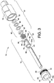
- the exemplary embodiment illustrates a male threaded nut 20 having male threads 22 and a female threaded body 18 having mating female threads 24, an alternative would be to have the nut 20 be female threaded and the body 18 be male threaded.
- the body 18 and the nut 20 may be joinable by many different techniques, including a mechanical connection other than a threaded mechanical connection 16.
- the body 18 and the nut 20 may be made of any suitable material, for example stainless steel or other metal, or may be made of non-metals, for example plastics or polymers or composite materials or other suitable materials, as needed.
- the conduit C is stainless steel or other metal
- the body 12 and the nut 14 are preferably made of metal and more preferably stainless steel alloy.
- the body 12 and the nut 14 are preferably all metal.
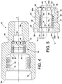
- An outwardly extending portion 76 of the ball cage 54 inner diameter through bore 62 optionally may be outwardly tapered so as not to apply stress to the conduit C (which can cause fretting) when possible system vibration may impart rotary flex or oscillation of the conduit C.
- the taper angle ⁇ and the length of the tapered portion 76 need only be large enough to reduce or prevent stress being applied to the conduit C by the ball cage 54. This will cause the stress from conduit oscillation or vibration to be concentrated more at the balls 56.
- a single action push to connect fitting assembly may be provided with a colleting portion or other such conduit engaging portion outboard of the gripping portion, for example, to collet or secure the conduit outboard of the gripping portion, thereby isolating the gripped portion of the conduit from flexure or vibration experienced by the conduit.
- the first ball set 94 may indent into the conduit surface in the range of approximately 0.0762 mm (.003 in) to 0.1016 mm (.004 in) and up to approximately 0.2032 mm (.008 in). These numbers and ranges are exemplary of course because the actual numbers will be adjusted based on materials used for the retainer parts and the conduit, conduit wall thickness, diameters and so on.
- the second ball set 104 may also contribute to conduit grip by also indenting into the conduit C outer surface, although this is more likely to be the case under elevated pressures. Conduit grip by the second ball set 104 may be a benefit realized in some designs and applications, but the first ball set 94 preferably is designed to provide sufficient and primary conduit grip and retention, while the second ball set 104 preferably is designed to collet the conduit or to provide isolation of conduit vibration and flex from the first ball set 94.
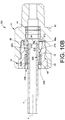
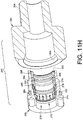
- Figs. 10A-10F illustrate another embodiment of a fitting assembly 200 that provides for a single action push to connect operation as in other embodiments hereinabove.
- This embodiment may be but need not be similar to the embodiments of Figs. 1-9 hereinabove except as otherwise noted. Therefore, the overall description does not need to be repeated and like reference numerals are used for like parts.
- Fig. 10A corresponds with Fig. 2 , and shows the fitting assembly 200 with the conduit C fully inserted and retained;
- Fig. 10B corresponds with Fig. 7 , and shows the conduit C partially inserted;
- Fig. 10C corresponds with Fig. 10A with the fitting assembly under pressure from a working fluid (not shown) contained by the fitting assembly 200; and
- Fig. 10D corresponds with Fig. 3 .
- Figs. 10E and 10F are enlarged perspective views of a retainer embodiment.
- each flexible member 306 At the distal end of each flexible member 306 is a tab 310 having a radially outer tab land or end portion 311, and a radially inner colleting surface 312 positioned to make direct contact with the outside surface of the conduit C as further described below. Because the retainer body 272 is annular, each flexible member 306 may have a curvature that coincides with the overall annular shape of the retainer body 272. Therefore, preferably but not necessarily, each colleting surface 312 is a curved surface that preferably but not necessarily coincides with the curvature of the conduit C, at least when the land 311 is radially pressed against the conduit C outer surface.
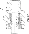
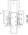
- the fitting assembly 350 may be but need not be similar or the same as the embodiment of Figs. 11A-11I above. In the illustrated embodiment of Figs. 12A and 12B , however, we omit the retaining member 280.
- the fitting assembly may include the retainer 270 having the ball carrier 272, the conduit gripping devices or balls 274, the biasing member 276 and the gland 278. Since we do not use the retaining member 280 in this embodiment, the gland 278 does not need to have the outer groove 290. Therefore, the retainer 270 is not held together as a subassembly with the second fitting component 352, which may be a male threaded nut.
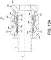
- conduit may alternatively have a groove or recess formed in the outer surface of the conduit wall at an axial position that aligns with the conduit gripping members such as the spherical balls.
- the groove or recess can in some applications enhance the conduit grip by the conduit gripping members because the balls will not have to be forced to indent into the conduit surface. Engagement of the conduit gripping members with the conduit groove may also provide a detectable positive indication of full insertion or installation of the conduit in the fitting assembly.
Claims (13)
- Ensemble raccord à connexion par poussée pour un conduit ayant un axe longitudinal, l'ensemble raccord comprenant :un premier composant de raccord (12, 252, 366, 382) ayant une extrémité extérieure qui est conçue pour recevoir une extrémité de conduit ;un second composant de raccord (14, 256, 352, 386) relié au premier composant de raccord pour définir une cavité intérieure ;un dispositif d'étanchéité (40) disposé dans la cavité intérieure, dans lequel le dispositif d'étanchéité tient de façon étanche l'un des premier et second composants de raccord avec une surface externe d'une extrémité de conduit (C) lorsque l'extrémité de conduit est insérée dans l'extrémité extérieure du premier composant de raccord ; etun dispositif de retenue (202, 270, 414) assemblé avec au moins l'un des premier et second composants de raccord, le dispositif de retenue comprenant un corps de dispositif de retenue annulaire (204, 272, 412) et une partie de préhension comprenant une pluralité d'éléments d'appui espacés circonférentiellement (56, 274, 416) capturés entre le corps de dispositif de retenue et le premier composant de raccord et/ou le second composant de raccord pour venir en prise avec l'extrémité de conduit insérée sur une première zone de contact de surface pour saisir l'extrémité de conduit,le dispositif de retenue comprenant en outre une partie collerette à l'extérieur de la partie de préhension, la partie collerette comprenant une pluralité de doigts radialement flexibles s'étendant axialement (216), chaque doigt flexible (216), au niveau d'une de ses extrémités distales, fait saillie radialement vers l'extérieur pour former une patte associée (218), les doigts (215) ayant des surfaces en contact avec le conduit (222) qui vienent en prise avec l'extrémité de conduit insérée sur une seconde zone de contact de surface plus grande que la première zone de contact de surface pour prendre dans une collerette l'extrémité de conduit insérée.
- Ensemble raccord selon la revendication 1, dans lequel le dispositif de retenue comprend en outre une seconde partie collerette (286') à l'intérieur de la partie de préhension.
- Ensemble raccord selon l'une quelconque des revendications 1 et 2, dans lequel chaque doigt radialement flexible s'étendant axialement de la pluralité de doigts radialement flexibles s'étendant axialement est d'un seul tenant avec le corps de dispositif de retenue.
- Ensemble raccord selon l'une quelconque des revendications 1 à 3, comprenant en outre un élément de sollicitation (58, 276, 408) disposé entre le second composant de raccord et le dispositif de retenue pour solliciter axialement le dispositif de retenue.
- Ensemble raccord selon la revendication 4, dans lequel le second composant de raccord comprend une surface intérieure effilée qui vient en prise avec les éléments d'appui et/ou les doigts flexibles pour déplacer les éléments d'appui et/ou les doigts flexibles radialement vers l'intérieur vers une mise en prise avec la surface externe de l'extrémité de conduit insérée.
- Ensemble raccord selon l'une quelconque des revendications 4 et 5, dans lequel l'élément de sollicitation sollicite axialement à la fois les éléments d'appui et les doigts flexibles en prise avec la surface intérieure effilée.
- Ensemble raccord selon l'une quelconque des revendications 1 à 6, dans lequel le dispositif d'étanchéité forme tout un joint étanche métallique entre l'un des premier et second composants de raccord et la surface externe de l'extrémité de conduit insérée.
- Ensemble raccord selon l'une quelconque des revendications 1 à 7, dans lequel le dispositif d'étanchéité comprend un joint à lèvre annulaire ayant une section transversale en forme de C orientée vers l'intérieur.
- Ensemble raccord selon la revendication 8, dans lequel le dispositif d'étanchéité comprend en outre un fouloir de support ayant une première extrémité adjacente à une partie d'épaulement interne du premier composant de raccord, et une seconde extrémité reçue dans la section transversale en forme de C du joint à lèvre annulaire.
- Ensemble raccord selon l'une quelconque des revendications 1 à 9, dans lequel les surfaces en contact avec le conduit des doigts flexibles définissent une surface interne incurvée correspondant à une surface externe cylindrique de l'extrémité de conduit insérée.
- Ensemble raccord selon l'une quelconque des revendications 1 à 10, dans lequel le second composant de raccord et le dispositif de retenue sont retenus ensemble sous la forme d'un sous-ensemble lorsque le second composant de raccord est désolidarisé du premier composant de raccord.
- Ensemble raccord selon l'une quelconque des revendications 1 à 11, dans lequel les surfaces en contact avec le conduit des doigts flexibles sont séparées de la surface externe de l'extrémité de conduit insérée par un espace radial lorsqu'aucune charge axiale dirigée vers l'extérieur n'est appliquée à l'extrémité de conduit insérée.
- Ensemble raccord selon l'une quelconque des revendications 1 à 12, dans lequel, lorsque l'extrémité de conduit est insérée dans l'extrémité extérieure du premier composant de raccord et qu'une pression fluidique est appliquée à l'ensemble raccord, le dispositif d'étanchéité est mis sous pression pour appliquer une force de sollicitation aux éléments d'appui pour solliciter les éléments d'appui vers une mise en prise de préhension avec l'extrémité de conduit insérée et aux doigts flexibles pour solliciter les doigts flexibles vers une mise en prise avec l'extrémité de conduit insérée en prenant dans une collerette.
Priority Applications (1)
| Application Number | Priority Date | Filing Date | Title |
|---|---|---|---|
| EP19194993.2A EP3597979B1 (fr) | 2015-04-23 | 2016-04-22 | Raccord de conduit de type pousser pour connecter avec serrage |
Applications Claiming Priority (2)
| Application Number | Priority Date | Filing Date | Title |
|---|---|---|---|
| US201562151465P | 2015-04-23 | 2015-04-23 | |
| PCT/US2016/028741 WO2016172408A1 (fr) | 2015-04-23 | 2016-04-22 | Raccord instantané à simple action pour conduit comprenant une collerette |
Related Child Applications (1)
| Application Number | Title | Priority Date | Filing Date |
|---|---|---|---|
| EP19194993.2A Division EP3597979B1 (fr) | 2015-04-23 | 2016-04-22 | Raccord de conduit de type pousser pour connecter avec serrage |
Publications (2)
| Publication Number | Publication Date |
|---|---|
| EP3286476A1 EP3286476A1 (fr) | 2018-02-28 |
| EP3286476B1 true EP3286476B1 (fr) | 2019-10-02 |
Family
ID=55861274
Family Applications (2)
| Application Number | Title | Priority Date | Filing Date |
|---|---|---|---|
| EP19194993.2A Active EP3597979B1 (fr) | 2015-04-23 | 2016-04-22 | Raccord de conduit de type pousser pour connecter avec serrage |
| EP16719710.2A Active EP3286476B1 (fr) | 2015-04-23 | 2016-04-22 | Raccord de conduit de type pousser pour connecter |
Family Applications Before (1)
| Application Number | Title | Priority Date | Filing Date |
|---|---|---|---|
| EP19194993.2A Active EP3597979B1 (fr) | 2015-04-23 | 2016-04-22 | Raccord de conduit de type pousser pour connecter avec serrage |
Country Status (9)
| Country | Link |
|---|---|
| US (2) | US10704722B2 (fr) |
| EP (2) | EP3597979B1 (fr) |
| JP (2) | JP6845155B2 (fr) |
| KR (1) | KR102534555B1 (fr) |
| CN (1) | CN107532758B (fr) |
| CA (1) | CA2983777A1 (fr) |
| ES (1) | ES2755400T3 (fr) |
| IL (1) | IL254950A0 (fr) |
| WO (1) | WO2016172408A1 (fr) |
Families Citing this family (7)
| Publication number | Priority date | Publication date | Assignee | Title |
|---|---|---|---|---|
| US10461514B2 (en) * | 2017-10-06 | 2019-10-29 | Quick Fitting, Inc. | Cable securing device |
| CN108533855A (zh) * | 2018-03-02 | 2018-09-14 | 广东思豪流体技术有限公司 | 一种连接头 |
| AU2019261571A1 (en) | 2018-04-24 | 2020-11-19 | Reliance Worldwide Corporation | Fluid connector |
| US11525534B2 (en) | 2018-08-14 | 2022-12-13 | Reliance Worldwide Corporation | Tubular connector |
| WO2021183911A1 (fr) | 2020-03-13 | 2021-09-16 | Reliance Worldwide Corporation | Raccord instantané donnant une indication d'insertion |
| WO2022089745A1 (fr) | 2020-10-29 | 2022-05-05 | Clearstream Technologies Limited | Connecteur pour le transfert d'un implant à un cathéter |
| CN114962826B (zh) * | 2022-06-16 | 2024-03-08 | 中海石油(中国)有限公司 | 一种水下液压加载可伸缩式连接器 |
Family Cites Families (207)
| Publication number | Priority date | Publication date | Assignee | Title |
|---|---|---|---|---|
| DE1987355U (de) | 1968-06-12 | Erich Wegner, 1000 Berlin | Anhängevorrichtung für Verkleidungsplatten u. dgl. an Betonflächen | |
| US1337288A (en) | 1918-05-07 | 1920-04-20 | Strause Gas Iron Co | Gas-fixture and fuel-hose therefor |
| US2062628A (en) | 1935-01-25 | 1936-12-01 | Yannetta Peter | Clutch lock |
| US2310744A (en) * | 1941-04-23 | 1943-02-09 | Alden E Osborn | Pipe joint |
| US2429202A (en) | 1943-02-05 | 1947-10-21 | B R Engineering Company | Fluid coupling |
| US2561887A (en) | 1948-11-16 | 1951-07-24 | Dresser Ind | Ball lock coupling |
| US2702202A (en) | 1950-06-23 | 1955-02-15 | Aeroquip Corp | Packed-socket pipe coupling with releasable pipe retaining means |
| US2914344A (en) | 1955-04-06 | 1959-11-24 | Union Carbide Corp | Quick detachable safety connection between blowpipe body and stem |
| US2848256A (en) * | 1955-11-21 | 1958-08-19 | Good All Electric Mfg Co | Pipe connector |
| US2848135A (en) | 1957-07-03 | 1958-08-19 | Mcdowell Mfg Co | Coupling nose fitting |
| AT228575B (de) | 1960-11-09 | 1963-07-25 | Rollmaplast Ag | Lösbare Muffenverbindung |
| US3398977A (en) | 1965-02-13 | 1968-08-27 | Yoneda Rikizo | Pipe coupling |
| US3453005A (en) | 1968-04-08 | 1969-07-01 | Scovill Manufacturing Co | Quick-connect safety coupling |
| US3773360A (en) | 1972-09-01 | 1973-11-20 | W Timbers | Quick disconnect coupling |
| US3887222A (en) | 1974-07-25 | 1975-06-03 | Hansen Mfg | Coupling with push-pull release |
| US4055359A (en) | 1975-11-17 | 1977-10-25 | Ford Motor Company | Quick-connect tubular couplings |
| AU509587B2 (en) | 1976-01-19 | 1980-05-15 | Sekisui Kagaku Kogyo Kabushiki Kaisha | Pipe joint endless locking ring and groove arrangement |
| US4105226A (en) | 1976-06-01 | 1978-08-08 | Celanese Corporation | Snap-in fittings and coupling ring therefor |
| US4163573A (en) | 1977-02-28 | 1979-08-07 | Chiyoda Tsusho K.K. | Hose fitting |
| US4191408A (en) | 1977-05-27 | 1980-03-04 | The Weatherhead Company | Automotive quick connect tube coupling |
| DE2741512A1 (de) | 1977-09-15 | 1979-04-05 | Kurt Schildmann | Schnellschlusskupplung |
| US4135745A (en) | 1977-12-23 | 1979-01-23 | Ford Motor Company | Quick connect fluid fitting |
| JPS5730545Y2 (fr) | 1978-04-29 | 1982-07-05 | ||
| US4193616A (en) | 1978-05-18 | 1980-03-18 | Dana Corporation | Quick connect fitting |
| DE2824943C2 (de) | 1978-06-07 | 1986-07-31 | Armaturenfabrik Hermann Voss GmbH + Co, 5272 Wipperfürth | Anschlußvorrichtung für Bremsleitungen |
| DE7914106U1 (de) | 1979-05-16 | 1979-08-23 | Gustav Eisele, Metallwarenfabrik, 7050 Waiblingen | Vorrichtung zum befestigen eines anschlussnippels an einem schlauch |
| DE2922869A1 (de) | 1979-06-06 | 1980-12-18 | Voss Armaturen | Verbindungssystem fuer druckleitungen |
| FR2461876A1 (fr) | 1979-07-23 | 1981-02-06 | Staubli Sa Ets | Perfectionnements aux dispositifs de raccord rapide pour la jonction des canalisations |
| US4240654A (en) | 1979-09-28 | 1980-12-23 | International Harvester Company | Hose end coupling unit |
| US4304422A (en) | 1980-02-19 | 1981-12-08 | Gould Inc. | Tube coupling with frangible sleeve |
| FR2479406B1 (fr) | 1980-03-28 | 1985-08-23 | Legris | Raccords instantanes pour tubes nus et lisses |
| JPS56151585U (fr) * | 1980-04-11 | 1981-11-13 | ||
| JPS5920462B2 (ja) | 1980-04-26 | 1984-05-14 | 株式会社サト− | 印字装置のリボン切れ検出機構 |
| GB2104607A (en) | 1981-08-21 | 1983-03-09 | Wilkinson Sword Ltd | Hose couplings |
| US4401326A (en) | 1981-12-16 | 1983-08-30 | Ford Motor Company | Quick-connect tubular coupling |
| US4752088A (en) | 1982-03-29 | 1988-06-21 | Carboloy Inc. | Tool adapter assembly and extended compression/tension tap driver |
| US4455177A (en) | 1982-09-13 | 1984-06-19 | Filippov Vladimir I | Method and apparatus for chemical heat treatment of steel parts utilizing a continuous electric furnace |
| FR2545908B1 (fr) | 1983-05-10 | 1985-07-12 | Staubli Sa Ets | Raccord rapide de securite pour la jonction amovible des canalisations |
| US4540201A (en) | 1983-05-16 | 1985-09-10 | Tuthill Corporation | Tube connector |
| GB8406580D0 (en) | 1984-03-13 | 1984-04-18 | Walmsley O | Pipe connector |
| DE3569604D1 (en) | 1984-03-13 | 1989-05-24 | Owen Walmsley | Clamps |
| FR2577300B1 (fr) | 1985-02-08 | 1987-08-21 | Fremy Raoul | Raccord rapide a verrouillage par verrou a deplacement radial |
| US4685706A (en) | 1985-03-04 | 1987-08-11 | Clevite Industries Inc. | Releasable push-to-connect tube fitting |
| US4645245A (en) | 1985-10-07 | 1987-02-24 | General Motors Corporation | Quick connect tube coupling |
| US4893810A (en) | 1986-07-21 | 1990-01-16 | Lee Scott H | Quick release collar |
| US4719971A (en) | 1986-08-18 | 1988-01-19 | Vetco Gray Inc. | Metal-to-metal/elastomeric pack-off assembly for subsea wellhead systems |
| US4802696A (en) * | 1986-10-23 | 1989-02-07 | The Gates Rubber Company | Quick connect coupling |
| US4813716A (en) | 1987-04-21 | 1989-03-21 | Titeflex Corporation | Quick connect end fitting |
| US4750765A (en) | 1987-07-27 | 1988-06-14 | Stratoflex, Inc. | Quick-connect coupling |
| US4793637A (en) | 1987-09-14 | 1988-12-27 | Aeroquip Corporation | Tube connector with indicator and release |
| US5042848A (en) | 1987-11-16 | 1991-08-27 | Fujipura Seiko Co. | Swivelable connector for tubular conduits |
| US4779107A (en) | 1987-12-21 | 1988-10-18 | Weisfield Richard L | Modulation electrodes having improved corrosion resistance |
| US4834423A (en) | 1987-12-22 | 1989-05-30 | Schmelzer Corporation | Quick connect fluid fitting assembly |
| US4906031A (en) | 1988-07-21 | 1990-03-06 | Stratoflex, Inc. | Quick connect coupling with garter spring |
| US4872710A (en) | 1988-10-07 | 1989-10-10 | Stratoflex, Inc. | Releasable quick connect fitting |
| US4900066A (en) | 1988-11-01 | 1990-02-13 | Vetco Gray Inc. | Pipe connector |
| US4923228A (en) | 1988-12-12 | 1990-05-08 | Aeroquip Corporation | Integral quick-connect tube connector |
| US5005877A (en) | 1988-12-16 | 1991-04-09 | Parker Hannifin Corporation | Quick connect/disconnect fluid coupling |
| CA2004975A1 (fr) | 1988-12-16 | 1990-06-16 | Lawrence F. Hayman | Raccord rapide |
| US5041997A (en) | 1989-02-06 | 1991-08-20 | Hewlett-Packard Company | Lightwave component analyzer |
| US5022687A (en) | 1989-09-18 | 1991-06-11 | Yokohama Aeroquip Corporation | Pipe coupling |
| US5176409A (en) | 1989-11-11 | 1993-01-05 | Dixie Iron Works | High pressure pipe coupling |
| US5024468A (en) | 1989-11-13 | 1991-06-18 | Parker Hannifin Corporation | Push-in tube fitting and release tool |
| US5076541A (en) | 1989-12-15 | 1991-12-31 | A. Y. Mcdonald Manufacturing Company | Tamperproof rotary valve |
| US5044672A (en) | 1990-03-22 | 1991-09-03 | Fmc Corporation | Metal-to-metal sealing pipe swivel joint |
| JPH0439492A (ja) * | 1990-05-31 | 1992-02-10 | Tokai Rubber Ind Ltd | クイックコネクタ |
| US5284369A (en) | 1990-08-24 | 1994-02-08 | Tokai Rubber Industries, Ltd. | Quick connector |
| US5044401A (en) | 1990-11-20 | 1991-09-03 | Parker Hannifin Corporation | Integral valve and seal for a quick connect coupling |
| AU7438891A (en) | 1991-04-29 | 1992-10-15 | Kabushiki Kaisha Harmo Sogo Kenkyujo | Tubing joint |
| JP2941499B2 (ja) | 1991-06-28 | 1999-08-25 | ミサワホーム株式会社 | 屋根ユニット用梱包枠 |
| US5118140A (en) * | 1991-08-09 | 1992-06-02 | Ramer Products, Inc. | Tool for smooth wall tubes |
| US5246236A (en) | 1992-01-21 | 1993-09-21 | Halliburton Company | Seal for long-time exposures in oil and gas well tools |
| US5301408A (en) | 1992-03-31 | 1994-04-12 | R & B, Inc. | Garter spring coupling release tool |
| US5401065A (en) | 1992-05-11 | 1995-03-28 | Kabushiki Kaisha Toshiba | Fluid coupling |
| JP2624924B2 (ja) | 1992-05-11 | 1997-06-25 | 株式会社東芝 | 流体継手 |
| US5226682A (en) | 1992-07-21 | 1993-07-13 | Aeroquip Corporation | Coupling assembly |
| US5292156A (en) * | 1992-09-11 | 1994-03-08 | Nitto Kohki Co., Ltd. | Corrugated pipe coupling |
| DE4243844B4 (de) | 1992-12-23 | 2004-03-25 | Voss Automotive Gmbh | Anschlußvorrichtung für Rohrleitungen |
| WO1994015131A1 (fr) | 1992-12-24 | 1994-07-07 | F.W. Talbot And Company Limited | Raccords |
| EP0615089A1 (fr) | 1993-03-06 | 1994-09-14 | DEUTSCHE TECALEMIT GmbH | Connexion enfichable et détachable pour conduits à haute pression |
| JP3562876B2 (ja) * | 1995-06-28 | 2004-09-08 | ブリヂストンフローテック株式会社 | 管継手 |
| JPH06272795A (ja) * | 1993-03-19 | 1994-09-27 | Bridgestone Flowtech Corp | 管継手 |
| US5653480A (en) * | 1993-03-19 | 1997-08-05 | Bridgestone Flowtech Corporation | Pipe coupling |
| JPH0830548B2 (ja) * | 1993-06-08 | 1996-03-27 | 榊原 明 | 管の接続装置 |
| JPH07190272A (ja) | 1993-12-28 | 1995-07-28 | Showa Alum Corp | パイプ接続装置 |
| US5470257A (en) | 1994-09-12 | 1995-11-28 | John Mezzalingua Assoc. Inc. | Radial compression type coaxial cable end connector |
| US5474336A (en) | 1994-09-20 | 1995-12-12 | Dana Corporation | Quick connect tube couplings |
| FR2727492B1 (fr) | 1994-11-30 | 1996-12-27 | Legris Sa | Dispositif de raccordement rapide d'un tube a un embout rigide |
| US5468028A (en) | 1994-12-19 | 1995-11-21 | Dana Corporation | Quick connect tube couplings |
| DE9420380U1 (de) | 1994-12-20 | 1995-02-02 | Voss Armaturen | Steckverbindung |
| GB9506183D0 (en) | 1995-03-27 | 1995-05-17 | Glynwed Plastics | Improvements in or relating to pipe couplings |
| US5553895A (en) | 1995-05-03 | 1996-09-10 | Aeroquip Corporation | Coupling assembly |
| DE19517269B4 (de) | 1995-05-11 | 2006-06-29 | Voss Automotive Gmbh | Anschlußvorrichtung für Rohrleitungen |
| US5562371A (en) | 1995-06-07 | 1996-10-08 | Lock-N-Stitch International | Tap with a non-cutting pilot |
| US5566987A (en) | 1995-06-12 | 1996-10-22 | Mazhar; Mohammad S. | Hose fitting assembly |
| US5570910A (en) | 1995-08-18 | 1996-11-05 | Aeroquip Corporation | Coupling assembly |
| US5662359A (en) | 1995-08-28 | 1997-09-02 | Form Rite | Quick connect coupling with lock ring and indicator |
| DE19533188A1 (de) | 1995-09-08 | 1997-03-13 | Man Nutzfahrzeuge Ag | Lösbare Steckverbindung für Druckluftanlagen in Fahrzeugen |
| SE506415C2 (sv) | 1995-10-02 | 1997-12-15 | Ericsson Telefon Ab L M | Arrangemang för att kyla elektroniska utrustningar |
| US5730475A (en) | 1995-10-13 | 1998-03-24 | Form Rite | Quick connect fluid coupling with collet retainer |
| US5685575A (en) | 1995-11-03 | 1997-11-11 | Aeroquip Corporation | Power steering coupling assembly |
| JPH09144970A (ja) * | 1995-11-17 | 1997-06-03 | Nichirin:Kk | ワンタッチ型セルフシール管継手 |
| US5683120A (en) | 1996-06-03 | 1997-11-04 | Parker-Hannifin Corporation | Releasable push-to-connect tube fitting |
| DE19709464C2 (de) | 1997-03-07 | 2000-03-09 | Voss Armaturen | Rohrverschraubung mit Schneidring für metallische Rohrleitungen |
| US7614668B1 (en) | 1997-04-15 | 2009-11-10 | Swagelok Company | Ferrule with plural inner diameters |
| US6629708B2 (en) | 1997-04-15 | 2003-10-07 | Swagelok Company | Ferrule with relief to reduce galling |
| TW473600B (en) | 1997-04-15 | 2002-01-21 | Swagelok Co | Tube fitting, rear ferrule for a two ferrule tube fitting and ferrule for a tube fitting and a non-flared tube fitting |
| US5882050A (en) | 1997-04-15 | 1999-03-16 | Williams; Peter C. | Ferrule with relief to reduce galling |
| GB2325718B (en) * | 1997-05-27 | 2002-07-31 | Hepworth Building Prod | Grab ring and socket incorporating a grab ring |
| DE29803195U1 (de) | 1998-02-24 | 1999-06-24 | Schaefer Stettiner Schrauben | Kombination aus einer Steckverbindung für Rohrleitungen und einem Lösewerkzeug |
| EP0898109B1 (fr) | 1997-08-19 | 2003-05-21 | Johannes Schäfer vormals Stettiner Schraubenwerke GmbH & Co. KG | Raccord emboitable pour tuyaux |
| JP3319712B2 (ja) | 1997-11-14 | 2002-09-03 | 日東工器株式会社 | 管継手の雌部材 |
| GB9724521D0 (en) | 1997-11-20 | 1998-01-21 | Munster Simms Engineering Limi | Pipe connections |
| US6056327A (en) | 1998-06-23 | 2000-05-02 | Pes, Inc. | High pressure hydraulic line connector |
| US6142538A (en) * | 1998-07-28 | 2000-11-07 | Perfection Corporation | Stab-type coupling with conduit inner diameter seal |
| CN100368721C (zh) | 1998-12-18 | 2008-02-13 | 爱考尔技术有限公司 | 管接头 |
| DE19932307A1 (de) | 1999-07-10 | 2001-01-11 | Schaefer Stettiner Schrauben | Lösbare Steckverbindung für Rohrleitungen |
| US6447017B1 (en) | 1999-10-29 | 2002-09-10 | The Gates Corporation | Fluid coupling and assembly |
| JP4420503B2 (ja) | 1999-12-24 | 2010-02-24 | 日東工器株式会社 | 管継手 |
| US6334634B1 (en) | 2000-06-20 | 2002-01-01 | International Truck And Engine Corporation | Push-to-connect tubing fitting |
| US6517126B1 (en) | 2000-09-22 | 2003-02-11 | General Electric Company | Internal swage fitting |
| US6588805B2 (en) | 2000-10-03 | 2003-07-08 | Eaton Aeroquip, Inc. | Coupling adapter and assembly |
| GB0024278D0 (en) | 2000-10-04 | 2000-11-15 | Bsw Ltd | A device for gripping a pipe or bar |
| US6510895B1 (en) | 2000-11-06 | 2003-01-28 | Fmc Technologies | Energized sealing cartridge for annulus sealing between tubular well components |
| US6494494B2 (en) | 2001-02-15 | 2002-12-17 | Eaton Aeroquip, Inc. | Coupling assembly |
| JP3550103B2 (ja) | 2001-03-29 | 2004-08-04 | 日東工器株式会社 | 管継手 |
| DE10125499C1 (de) | 2001-05-23 | 2002-08-14 | Schaefer Stettiner Schrauben | Steckverbindung, insbesondere für Rohrleitungen |
| JP4585714B2 (ja) | 2001-06-28 | 2010-11-24 | Jfe継手株式会社 | 差込み式管継手に差し込まれる管の端部構造 |
| US6604760B2 (en) | 2001-06-29 | 2003-08-12 | Parker-Hannifin Corporation | Quick connect/disconnect coupling |
| KR200260578Y1 (ko) * | 2001-08-02 | 2002-01-10 | 주식회사 조인탑 | 파이프 커플링 |
| DE10206852B4 (de) | 2002-02-18 | 2009-02-12 | Walterscheid Rohrverbindungstechnik Gmbh | Kupplung zum Verbinden von Hydraulikleitungen |
| GB2387420B (en) | 2002-02-18 | 2004-05-05 | Walterscheid Gmbh Jean | Coupling for connecting hydraulic ducts |
| US7140645B2 (en) | 2002-06-27 | 2006-11-28 | Gerald Cronley | Quick-connecting coupler for hoses, pipes and faucets |
| US6769720B2 (en) | 2002-08-27 | 2004-08-03 | Eaton Corporation | Coupling assembly with profiled ramp |
| FR2844335B1 (fr) | 2002-09-05 | 2008-05-16 | Legris Sa | Moyens de connexion de conduits pour fluides haute pression |
| JP4252785B2 (ja) | 2002-10-01 | 2009-04-08 | 株式会社パイオラックス | 配管用コネクタ及びその製造方法 |
| JP4291989B2 (ja) | 2002-10-01 | 2009-07-08 | 株式会社パイオラックス | 配管用コネクタ |
| JP4381676B2 (ja) * | 2002-12-02 | 2009-12-09 | ブリヂストンフローテック株式会社 | 管継手構造 |
| GB2398612A (en) | 2003-02-21 | 2004-08-25 | Glynwed Pipe Systems Ltd | Pipe coupling |
| US7506899B2 (en) | 2003-03-20 | 2009-03-24 | Rain Bird Corporation | Multi-diameter tube fitting |
| US6877781B2 (en) | 2003-07-31 | 2005-04-12 | Highlands Corporation | Corrugated tube fitting |
| US7029035B2 (en) | 2003-09-11 | 2006-04-18 | International Engine Intellectual Property Company, Llc | Release collar for coupling assembly |
| US7374867B2 (en) | 2003-10-06 | 2008-05-20 | Intel Corporation | Enhancing photoresist performance using electric fields |
| JP2005172218A (ja) | 2003-11-21 | 2005-06-30 | Hama International:Kk | 管継手 |
| US7208052B2 (en) | 2003-12-23 | 2007-04-24 | Rolls-Royce Corporation | Method for carburizing steel components |
| US6893051B1 (en) * | 2003-12-31 | 2005-05-17 | Join Top Co., Ltd. | Pipe coupling |
| CA2554681C (fr) | 2004-01-27 | 2011-06-21 | Eaton Corporation | Ensemble couplage comportant un manchon de verrouillage |
| US7488006B2 (en) | 2004-02-02 | 2009-02-10 | Eaton Corporation | Coupling assembly |
| FR2865789B1 (fr) | 2004-02-04 | 2006-03-10 | Legris Sa | Raccord a couplage instantane |
| JP2005330983A (ja) * | 2004-05-18 | 2005-12-02 | Riken Corp | メカニカル式管継手 |
| US8240719B2 (en) | 2004-07-21 | 2012-08-14 | Parker-Hannifin Corporation | Adaptor and method for converting standard tube fitting/port to push-to-connect tube fitting/port |
| MX2007002145A (es) | 2004-07-21 | 2007-09-14 | Parker Hannifin Corp | Adaptador y metodo para convertir un ajuste/puerto de tubo estandar en un ajuste/puerto de tubo de tipo presione-para- conectar. |
| KR100593285B1 (ko) * | 2004-08-16 | 2006-06-26 | 김석윤 | 파이프 고정장치 |
| JP4699730B2 (ja) | 2004-09-14 | 2011-06-15 | 株式会社東海 | ロック機構付コネクタ構造 |
| GB0504899D0 (en) * | 2005-03-09 | 2005-04-13 | Guest John Int Ltd | Improvements in or relating to tube couplings |
| JP2006313010A (ja) | 2005-04-04 | 2006-11-16 | Denso Corp | 配管継手装置 |
| WO2006136166A1 (fr) | 2005-06-22 | 2006-12-28 | Danmarks Tekniske Universitet - Dtu | Cementation au moyen d'un gaz hydrocarbone |
| US7484776B2 (en) | 2005-07-14 | 2009-02-03 | Stinger Wellhead Protection, Inc. | High-pressure threaded union with metal-to-metal seal, and metal ring gasket for same |
| DE102005043708A1 (de) | 2005-09-14 | 2007-03-22 | GM Global Technology Operations, Inc., Detroit | Vorrichtung zur Aufpralldämpfung |
| JP4628931B2 (ja) * | 2005-11-04 | 2011-02-09 | 日東工器株式会社 | 雄雌部材アセンブリ |
| US7369595B2 (en) | 2005-12-06 | 2008-05-06 | Electronics And Telecommunications Research Institute | Distributed Bragg reflector (DBR) structure in vertical cavity surface emitting laser (VCSEL) diode, method of manufacturing the same, and VCSEL diode |
| US7850208B2 (en) | 2005-12-14 | 2010-12-14 | Parker-Hannifin Corporation | Stamped collet for push-to-connect tube fittings |
| KR20080091186A (ko) | 2006-01-13 | 2008-10-09 | 스와겔로크 컴패니 | 튜브 또는 파이프용 이음쇠 |
| DE602006008668D1 (de) | 2006-01-20 | 2009-10-01 | Parker Hannifin Corp | Adapter und verfahren zur umwandlung eines standardmässigen rohranschlussstück/-kanals zu einem push-to-connect-rohranschlussstück/-kanal |
| JPWO2007088780A1 (ja) | 2006-01-31 | 2009-06-25 | 株式会社ミツバ | ワイパブレードにおける連結部材 |
| US7293758B2 (en) * | 2006-03-10 | 2007-11-13 | Lai Chang Hsueh-Feng | Pipe connector |
| DE102006015555B3 (de) | 2006-03-31 | 2007-01-25 | Fte Automotive Gmbh | Dichtungsanordnung für eine hydraulische Steckverbindung |
| WO2007117688A2 (fr) | 2006-04-06 | 2007-10-18 | Parker-Hannifin Corporation | couplage à connexion par poussée pour des applications de pression |
| US7533908B2 (en) | 2006-07-19 | 2009-05-19 | Eaton Corporation | Coupling assembly and retainer for use with same |
| FR2907188B1 (fr) * | 2006-10-13 | 2010-10-08 | Staubli Sa Ets | Element femelle de raccord et raccord incorporant un tel element |
| WO2008051500A1 (fr) | 2006-10-23 | 2008-05-02 | Swagelok Company | Système d'installation pour dispositif de serrage de conduit |
| US7419012B2 (en) | 2006-10-26 | 2008-09-02 | Varco I/P, Inc. | Wellbore top drive systems |
| DE202006018794U1 (de) | 2006-12-11 | 2008-04-10 | Johannes Schäfer vorm. Stettiner Schraubenwerke GmbH & Co. KG | Steckverbindung für Rohrleitungen |
| US7806443B1 (en) | 2007-03-16 | 2010-10-05 | Plattner Wesley M | Method and apparatus for connecting air conditioning coolant lines |
| US8985131B2 (en) | 2007-06-30 | 2015-03-24 | Koolance, Inc. | Coupling with automatic seal |
| DE202007013316U1 (de) * | 2007-09-21 | 2009-02-12 | Voss Automotive Gmbh | Anschlussvorrichtung für Medienleitungen |
| DE102008038480A1 (de) | 2008-08-20 | 2010-03-11 | Viega Gmbh & Co. Kg | Außenabdichtender Steckverbinder |
| CN102203491A (zh) | 2008-08-31 | 2011-09-28 | 戴维斯·A·怀特 | 非旋转联接装置 |
| US20100171302A1 (en) | 2009-01-05 | 2010-07-08 | Nibco Inc. | Push-twist connector |
| US8312922B2 (en) | 2009-06-02 | 2012-11-20 | Vetco Gray Inc. | Metal-to-metal seal with travel seal bands |
| CA2797176C (fr) | 2010-02-18 | 2015-01-06 | Sung-Hun Kim | Dispositif de raccordement de tube en un seul geste |
| WO2011116271A1 (fr) | 2010-03-18 | 2011-09-22 | Swagelok Company | Raccord pour tubes gainés |
| FR2958713B1 (fr) | 2010-04-13 | 2012-06-08 | Legris Sas | Dispositif de raccordement d'un tube a un element de circuit, procede de montage d'une rondelle d'ancrage sur un corps d'un tel dispositif de raccordement et procede de demontage d'un tel dispositif |
| WO2011137924A1 (fr) * | 2010-05-03 | 2011-11-10 | Agilent Technologies, Inc. | Élément d'ajustement comportant un élément de force de serrage hydraulique |
| GB2480880B (en) | 2010-06-04 | 2016-03-16 | Polypipe Ltd | Pipe connection and collet release tool |
| CN103026118A (zh) | 2010-07-26 | 2013-04-03 | 世伟洛克公司 | 单轴推动连接导管接头 |
| CN103201551B (zh) | 2010-10-15 | 2016-09-07 | 世伟洛克公司 | 具有套管的推动连接管接头 |
| KR101007546B1 (ko) | 2010-10-15 | 2011-01-14 | (주)럭키텍 | 이음관 내부에 구성되는 파이프 연결구 |
| US9243711B2 (en) | 2011-07-19 | 2016-01-26 | Vetco Gray Inc. | Bi-directional pressure energized axial seal and a swivel connection application |
| EP2589848A4 (fr) | 2011-09-02 | 2015-05-27 | Water Take Co Ltd | Appareil de raccordement de tuyaux du type à touche unique |
| WO2013056273A2 (fr) | 2011-10-12 | 2013-04-18 | Livizone (Pty) Ltd | Raccord du type pousser ajuster doté d'écrou de maintien pour tuyaux |
| FR2987097B1 (fr) | 2012-02-20 | 2014-04-11 | Parker Hannifin Mfg France Sas | Dispositif de raccordement etanche sans zone de retention |
| GB201205577D0 (en) * | 2012-03-29 | 2012-05-16 | Guest John Int Ltd | Improvements in or relating to tube couplings |
| JP6077333B2 (ja) * | 2013-02-21 | 2017-02-08 | ジョプラックス株式会社 | ロックボール式管継手 |
| CN109555926B (zh) * | 2013-10-24 | 2021-07-02 | 世伟洛克公司 | 单动推动即可连接管道接头 |
| FR3014167B1 (fr) | 2013-11-29 | 2015-12-18 | Parker Hannifin Mfg France Sas | Dispositif de raccordement rapide de type cartouche |
| US10006575B2 (en) | 2013-12-11 | 2018-06-26 | Nibco Inc. | Modular push-to-connect assembly |
| US9541228B2 (en) | 2013-12-11 | 2017-01-10 | Nibco Inc. | Push-to-connect fitting |
| US9447906B2 (en) | 2013-12-11 | 2016-09-20 | Nibco Inc. | Self-locking push-to-connect insert |
| WO2015089583A2 (fr) | 2013-12-19 | 2015-06-25 | Gsa Industries (Aust.) Pty Ltd | Raccord de connexion de conduite |
| US9777875B2 (en) | 2014-02-26 | 2017-10-03 | Nibco Inc. | Clam shell push-to-connect assembly |
| US10044177B2 (en) | 2014-03-13 | 2018-08-07 | Hubbell Incorporated | Push to connect weatherproof box |
| US10094500B2 (en) | 2014-05-30 | 2018-10-09 | Quick Fitting, Inc. | Push-to-connect fitting integrated packing arrangement, device and methods |
| US9923354B2 (en) | 2014-07-25 | 2018-03-20 | Quick Fitting, Inc. | Integrated piping conduit with adaptor device and method |
| US9816655B2 (en) | 2014-12-09 | 2017-11-14 | Quick Fitting, Inc. | Rotation locking push-to-connect fitting device, system and method |
| US10458582B2 (en) | 2015-04-23 | 2019-10-29 | Swagelok Company | Single action push to connect conduit fitting with colleting |
| US9879810B2 (en) | 2015-09-18 | 2018-01-30 | Quick Fitting, Inc. | Push-to-connect joint assembly with protective shield device and method |
-
2016
- 2016-04-22 CN CN201680023393.5A patent/CN107532758B/zh active Active
- 2016-04-22 WO PCT/US2016/028741 patent/WO2016172408A1/fr active Application Filing
- 2016-04-22 JP JP2017554846A patent/JP6845155B2/ja active Active
- 2016-04-22 ES ES16719710T patent/ES2755400T3/es active Active
- 2016-04-22 EP EP19194993.2A patent/EP3597979B1/fr active Active
- 2016-04-22 KR KR1020177033818A patent/KR102534555B1/ko active IP Right Grant
- 2016-04-22 EP EP16719710.2A patent/EP3286476B1/fr active Active
- 2016-04-22 CA CA2983777A patent/CA2983777A1/fr not_active Abandoned
-
2017
- 2017-10-09 IL IL254950A patent/IL254950A0/en unknown
-
2019
- 2019-06-11 US US16/437,095 patent/US10704722B2/en active Active
-
2020
- 2020-05-19 US US16/877,564 patent/US11073234B2/en active Active
-
2021
- 2021-02-25 JP JP2021028222A patent/JP2021081073A/ja active Pending
Non-Patent Citations (1)
| Title |
|---|
| None * |
Also Published As
| Publication number | Publication date |
|---|---|
| CN107532758B (zh) | 2020-10-13 |
| US20200278064A1 (en) | 2020-09-03 |
| CA2983777A1 (fr) | 2016-10-27 |
| ES2755400T3 (es) | 2020-04-22 |
| KR102534555B1 (ko) | 2023-05-18 |
| IL254950A0 (en) | 2017-12-31 |
| EP3286476A1 (fr) | 2018-02-28 |
| JP2018513948A (ja) | 2018-05-31 |
| US10704722B2 (en) | 2020-07-07 |
| US11073234B2 (en) | 2021-07-27 |
| EP3597979B1 (fr) | 2021-09-29 |
| EP3597979A1 (fr) | 2020-01-22 |
| US20190293218A1 (en) | 2019-09-26 |
| CN107532758A (zh) | 2018-01-02 |
| JP6845155B2 (ja) | 2021-03-17 |
| KR20180009756A (ko) | 2018-01-29 |
| WO2016172408A8 (fr) | 2017-10-19 |
| JP2021081073A (ja) | 2021-05-27 |
| WO2016172408A1 (fr) | 2016-10-27 |
Similar Documents
| Publication | Publication Date | Title |
|---|---|---|
| US10458582B2 (en) | Single action push to connect conduit fitting with colleting | |
| US10619780B2 (en) | Single action push to connect conduit fitting | |
| US11073234B2 (en) | Single action push to connect conduit fitting | |
| US11002395B2 (en) | Push to connect conduit fitting with ferrule | |
| RU2711704C2 (ru) | Обжимной фитинг | |
| US4088350A (en) | Plastic tubing connector | |
| JP2023501060A (ja) | クイックコネクタ | |
| JP2021050748A (ja) | 管継手および管の取り外し方法 | |
| US20060175831A1 (en) | Fluid quick connect contamination cover | |
| EP1691124A2 (fr) | Raccord fluidique rapide avec couvercle de la contamination | |
| WO2021231645A1 (fr) | Raccord, ensemble raccord et adaptateur de couple | |
| JP2003028364A (ja) | 差込式管継手 | |
| JP2019018840A (ja) | 自転車のブレーキシステムに用いられる液圧封止体、および自転車のブレーキシステムに用いられる液圧ホースアセンブリ | |
| JPH0689867B2 (ja) | ブレーキ配管迅速接続継手 |
Legal Events
| Date | Code | Title | Description |
|---|---|---|---|
| STAA | Information on the status of an ep patent application or granted ep patent |
Free format text: STATUS: THE INTERNATIONAL PUBLICATION HAS BEEN MADE |
|
| PUAI | Public reference made under article 153(3) epc to a published international application that has entered the european phase |
Free format text: ORIGINAL CODE: 0009012 |
|
| STAA | Information on the status of an ep patent application or granted ep patent |
Free format text: STATUS: REQUEST FOR EXAMINATION WAS MADE |
|
| 17P | Request for examination filed |
Effective date: 20171012 |
|
| AK | Designated contracting states |
Kind code of ref document: A1 Designated state(s): AL AT BE BG CH CY CZ DE DK EE ES FI FR GB GR HR HU IE IS IT LI LT LU LV MC MK MT NL NO PL PT RO RS SE SI SK SM TR |
|
| AX | Request for extension of the european patent |
Extension state: BA ME |
|
| DAV | Request for validation of the european patent (deleted) | ||
| DAX | Request for extension of the european patent (deleted) | ||
| STAA | Information on the status of an ep patent application or granted ep patent |
Free format text: STATUS: EXAMINATION IS IN PROGRESS |
|
| 17Q | First examination report despatched |
Effective date: 20181116 |
|
| GRAP | Despatch of communication of intention to grant a patent |
Free format text: ORIGINAL CODE: EPIDOSNIGR1 |
|
| STAA | Information on the status of an ep patent application or granted ep patent |
Free format text: STATUS: GRANT OF PATENT IS INTENDED |
|
| INTG | Intention to grant announced |
Effective date: 20190509 |
|
| GRAS | Grant fee paid |
Free format text: ORIGINAL CODE: EPIDOSNIGR3 |
|
| GRAA | (expected) grant |
Free format text: ORIGINAL CODE: 0009210 |
|
| STAA | Information on the status of an ep patent application or granted ep patent |
Free format text: STATUS: THE PATENT HAS BEEN GRANTED |
|
| AK | Designated contracting states |
Kind code of ref document: B1 Designated state(s): AL AT BE BG CH CY CZ DE DK EE ES FI FR GB GR HR HU IE IS IT LI LT LU LV MC MK MT NL NO PL PT RO RS SE SI SK SM TR |
|
| REG | Reference to a national code |
Ref country code: GB Ref legal event code: FG4D |
|
| REG | Reference to a national code |
Ref country code: CH Ref legal event code: EP Ref country code: AT Ref legal event code: REF Ref document number: 1186568 Country of ref document: AT Kind code of ref document: T Effective date: 20191015 |
|
| REG | Reference to a national code |
Ref country code: DE Ref legal event code: R096 Ref document number: 602016021665 Country of ref document: DE |
|
| REG | Reference to a national code |
Ref country code: IE Ref legal event code: FG4D |
|
| REG | Reference to a national code |
Ref country code: NL Ref legal event code: MP Effective date: 20191002 |
|
| REG | Reference to a national code |
Ref country code: LT Ref legal event code: MG4D |
|
| REG | Reference to a national code |
Ref country code: AT Ref legal event code: MK05 Ref document number: 1186568 Country of ref document: AT Kind code of ref document: T Effective date: 20191002 |
|
| REG | Reference to a national code |
Ref country code: ES Ref legal event code: FG2A Ref document number: 2755400 Country of ref document: ES Kind code of ref document: T3 Effective date: 20200422 |
|
| PG25 | Lapsed in a contracting state [announced via postgrant information from national office to epo] |
Ref country code: LV Free format text: LAPSE BECAUSE OF FAILURE TO SUBMIT A TRANSLATION OF THE DESCRIPTION OR TO PAY THE FEE WITHIN THE PRESCRIBED TIME-LIMIT Effective date: 20191002 Ref country code: AT Free format text: LAPSE BECAUSE OF FAILURE TO SUBMIT A TRANSLATION OF THE DESCRIPTION OR TO PAY THE FEE WITHIN THE PRESCRIBED TIME-LIMIT Effective date: 20191002 Ref country code: PL Free format text: LAPSE BECAUSE OF FAILURE TO SUBMIT A TRANSLATION OF THE DESCRIPTION OR TO PAY THE FEE WITHIN THE PRESCRIBED TIME-LIMIT Effective date: 20191002 Ref country code: BG Free format text: LAPSE BECAUSE OF FAILURE TO SUBMIT A TRANSLATION OF THE DESCRIPTION OR TO PAY THE FEE WITHIN THE PRESCRIBED TIME-LIMIT Effective date: 20200102 Ref country code: SE Free format text: LAPSE BECAUSE OF FAILURE TO SUBMIT A TRANSLATION OF THE DESCRIPTION OR TO PAY THE FEE WITHIN THE PRESCRIBED TIME-LIMIT Effective date: 20191002 Ref country code: PT Free format text: LAPSE BECAUSE OF FAILURE TO SUBMIT A TRANSLATION OF THE DESCRIPTION OR TO PAY THE FEE WITHIN THE PRESCRIBED TIME-LIMIT Effective date: 20200203 Ref country code: FI Free format text: LAPSE BECAUSE OF FAILURE TO SUBMIT A TRANSLATION OF THE DESCRIPTION OR TO PAY THE FEE WITHIN THE PRESCRIBED TIME-LIMIT Effective date: 20191002 Ref country code: NO Free format text: LAPSE BECAUSE OF FAILURE TO SUBMIT A TRANSLATION OF THE DESCRIPTION OR TO PAY THE FEE WITHIN THE PRESCRIBED TIME-LIMIT Effective date: 20200102 Ref country code: GR Free format text: LAPSE BECAUSE OF FAILURE TO SUBMIT A TRANSLATION OF THE DESCRIPTION OR TO PAY THE FEE WITHIN THE PRESCRIBED TIME-LIMIT Effective date: 20200103 Ref country code: LT Free format text: LAPSE BECAUSE OF FAILURE TO SUBMIT A TRANSLATION OF THE DESCRIPTION OR TO PAY THE FEE WITHIN THE PRESCRIBED TIME-LIMIT Effective date: 20191002 Ref country code: NL Free format text: LAPSE BECAUSE OF FAILURE TO SUBMIT A TRANSLATION OF THE DESCRIPTION OR TO PAY THE FEE WITHIN THE PRESCRIBED TIME-LIMIT Effective date: 20191002 |
|
| PG25 | Lapsed in a contracting state [announced via postgrant information from national office to epo] |
Ref country code: HR Free format text: LAPSE BECAUSE OF FAILURE TO SUBMIT A TRANSLATION OF THE DESCRIPTION OR TO PAY THE FEE WITHIN THE PRESCRIBED TIME-LIMIT Effective date: 20191002 Ref country code: IS Free format text: LAPSE BECAUSE OF FAILURE TO SUBMIT A TRANSLATION OF THE DESCRIPTION OR TO PAY THE FEE WITHIN THE PRESCRIBED TIME-LIMIT Effective date: 20200224 Ref country code: CZ Free format text: LAPSE BECAUSE OF FAILURE TO SUBMIT A TRANSLATION OF THE DESCRIPTION OR TO PAY THE FEE WITHIN THE PRESCRIBED TIME-LIMIT Effective date: 20191002 Ref country code: RS Free format text: LAPSE BECAUSE OF FAILURE TO SUBMIT A TRANSLATION OF THE DESCRIPTION OR TO PAY THE FEE WITHIN THE PRESCRIBED TIME-LIMIT Effective date: 20191002 |
|
| PG25 | Lapsed in a contracting state [announced via postgrant information from national office to epo] |
Ref country code: AL Free format text: LAPSE BECAUSE OF FAILURE TO SUBMIT A TRANSLATION OF THE DESCRIPTION OR TO PAY THE FEE WITHIN THE PRESCRIBED TIME-LIMIT Effective date: 20191002 |
|
| REG | Reference to a national code |
Ref country code: DE Ref legal event code: R097 Ref document number: 602016021665 Country of ref document: DE |
|
| PG2D | Information on lapse in contracting state deleted |
Ref country code: IS |
|
| PG25 | Lapsed in a contracting state [announced via postgrant information from national office to epo] |
Ref country code: RO Free format text: LAPSE BECAUSE OF FAILURE TO SUBMIT A TRANSLATION OF THE DESCRIPTION OR TO PAY THE FEE WITHIN THE PRESCRIBED TIME-LIMIT Effective date: 20191002 Ref country code: EE Free format text: LAPSE BECAUSE OF FAILURE TO SUBMIT A TRANSLATION OF THE DESCRIPTION OR TO PAY THE FEE WITHIN THE PRESCRIBED TIME-LIMIT Effective date: 20191002 Ref country code: DK Free format text: LAPSE BECAUSE OF FAILURE TO SUBMIT A TRANSLATION OF THE DESCRIPTION OR TO PAY THE FEE WITHIN THE PRESCRIBED TIME-LIMIT Effective date: 20191002 Ref country code: IS Free format text: LAPSE BECAUSE OF FAILURE TO SUBMIT A TRANSLATION OF THE DESCRIPTION OR TO PAY THE FEE WITHIN THE PRESCRIBED TIME-LIMIT Effective date: 20200202 |
|
| PLBE | No opposition filed within time limit |
Free format text: ORIGINAL CODE: 0009261 |
|
| STAA | Information on the status of an ep patent application or granted ep patent |
Free format text: STATUS: NO OPPOSITION FILED WITHIN TIME LIMIT |
|
| PG25 | Lapsed in a contracting state [announced via postgrant information from national office to epo] |
Ref country code: SK Free format text: LAPSE BECAUSE OF FAILURE TO SUBMIT A TRANSLATION OF THE DESCRIPTION OR TO PAY THE FEE WITHIN THE PRESCRIBED TIME-LIMIT Effective date: 20191002 Ref country code: SM Free format text: LAPSE BECAUSE OF FAILURE TO SUBMIT A TRANSLATION OF THE DESCRIPTION OR TO PAY THE FEE WITHIN THE PRESCRIBED TIME-LIMIT Effective date: 20191002 |
|
| 26N | No opposition filed |
Effective date: 20200703 |
|
| PG25 | Lapsed in a contracting state [announced via postgrant information from national office to epo] |
Ref country code: MC Free format text: LAPSE BECAUSE OF FAILURE TO SUBMIT A TRANSLATION OF THE DESCRIPTION OR TO PAY THE FEE WITHIN THE PRESCRIBED TIME-LIMIT Effective date: 20191002 Ref country code: SI Free format text: LAPSE BECAUSE OF FAILURE TO SUBMIT A TRANSLATION OF THE DESCRIPTION OR TO PAY THE FEE WITHIN THE PRESCRIBED TIME-LIMIT Effective date: 20191002 |
|
| REG | Reference to a national code |
Ref country code: CH Ref legal event code: PL |
|
| PG25 | Lapsed in a contracting state [announced via postgrant information from national office to epo] |
Ref country code: LU Free format text: LAPSE BECAUSE OF NON-PAYMENT OF DUE FEES Effective date: 20200422 Ref country code: LI Free format text: LAPSE BECAUSE OF NON-PAYMENT OF DUE FEES Effective date: 20200430 Ref country code: CH Free format text: LAPSE BECAUSE OF NON-PAYMENT OF DUE FEES Effective date: 20200430 |
|
| REG | Reference to a national code |
Ref country code: BE Ref legal event code: MM Effective date: 20200430 |
|
| PG25 | Lapsed in a contracting state [announced via postgrant information from national office to epo] |
Ref country code: BE Free format text: LAPSE BECAUSE OF NON-PAYMENT OF DUE FEES Effective date: 20200430 |
|
| PG25 | Lapsed in a contracting state [announced via postgrant information from national office to epo] |
Ref country code: IE Free format text: LAPSE BECAUSE OF NON-PAYMENT OF DUE FEES Effective date: 20200422 |
|
| PGFP | Annual fee paid to national office [announced via postgrant information from national office to epo] |
Ref country code: GB Payment date: 20210427 Year of fee payment: 6 Ref country code: ES Payment date: 20210504 Year of fee payment: 6 |
|
| PG25 | Lapsed in a contracting state [announced via postgrant information from national office to epo] |
Ref country code: TR Free format text: LAPSE BECAUSE OF FAILURE TO SUBMIT A TRANSLATION OF THE DESCRIPTION OR TO PAY THE FEE WITHIN THE PRESCRIBED TIME-LIMIT Effective date: 20191002 Ref country code: MT Free format text: LAPSE BECAUSE OF FAILURE TO SUBMIT A TRANSLATION OF THE DESCRIPTION OR TO PAY THE FEE WITHIN THE PRESCRIBED TIME-LIMIT Effective date: 20191002 Ref country code: CY Free format text: LAPSE BECAUSE OF FAILURE TO SUBMIT A TRANSLATION OF THE DESCRIPTION OR TO PAY THE FEE WITHIN THE PRESCRIBED TIME-LIMIT Effective date: 20191002 |
|
| PG25 | Lapsed in a contracting state [announced via postgrant information from national office to epo] |
Ref country code: MK Free format text: LAPSE BECAUSE OF FAILURE TO SUBMIT A TRANSLATION OF THE DESCRIPTION OR TO PAY THE FEE WITHIN THE PRESCRIBED TIME-LIMIT Effective date: 20191002 |
|
| PGFP | Annual fee paid to national office [announced via postgrant information from national office to epo] |
Ref country code: FR Payment date: 20220425 Year of fee payment: 7 |
|
| GBPC | Gb: european patent ceased through non-payment of renewal fee |
Effective date: 20220422 |
|
| PG25 | Lapsed in a contracting state [announced via postgrant information from national office to epo] |
Ref country code: GB Free format text: LAPSE BECAUSE OF NON-PAYMENT OF DUE FEES Effective date: 20220422 |
|
| REG | Reference to a national code |
Ref country code: ES Ref legal event code: FD2A Effective date: 20230601 |
|
| P01 | Opt-out of the competence of the unified patent court (upc) registered |
Effective date: 20230526 |
|
| PG25 | Lapsed in a contracting state [announced via postgrant information from national office to epo] |
Ref country code: ES Free format text: LAPSE BECAUSE OF NON-PAYMENT OF DUE FEES Effective date: 20220423 |
|
| PGFP | Annual fee paid to national office [announced via postgrant information from national office to epo] |
Ref country code: IT Payment date: 20230419 Year of fee payment: 8 Ref country code: DE Payment date: 20230427 Year of fee payment: 8 |
|
| PG25 | Lapsed in a contracting state [announced via postgrant information from national office to epo] |
Ref country code: FR Free format text: LAPSE BECAUSE OF NON-PAYMENT OF DUE FEES Effective date: 20230430 |