EP3286476B1 - Push to connect fitting assembly for a conduit - Google Patents
Push to connect fitting assembly for a conduit Download PDFInfo
- Publication number
- EP3286476B1 EP3286476B1 EP16719710.2A EP16719710A EP3286476B1 EP 3286476 B1 EP3286476 B1 EP 3286476B1 EP 16719710 A EP16719710 A EP 16719710A EP 3286476 B1 EP3286476 B1 EP 3286476B1
- Authority
- EP
- European Patent Office
- Prior art keywords
- conduit
- fitting
- retainer
- fitting assembly
- ball
- Prior art date
- Legal status (The legal status is an assumption and is not a legal conclusion. Google has not performed a legal analysis and makes no representation as to the accuracy of the status listed.)
- Active
Links
- 239000012530 fluid Substances 0.000 claims description 38
- 210000004907 gland Anatomy 0.000 claims description 32
- 229910052751 metal Inorganic materials 0.000 claims description 19
- 239000002184 metal Substances 0.000 claims description 19
- 230000000717 retained effect Effects 0.000 claims description 8
- 230000009471 action Effects 0.000 description 42
- 230000033001 locomotion Effects 0.000 description 29
- 238000003780 insertion Methods 0.000 description 18
- 230000037431 insertion Effects 0.000 description 18
- 239000000463 material Substances 0.000 description 12
- 230000035882 stress Effects 0.000 description 11
- 230000014759 maintenance of location Effects 0.000 description 10
- 238000007373 indentation Methods 0.000 description 8
- 230000006835 compression Effects 0.000 description 7
- 238000007906 compression Methods 0.000 description 7
- 229910052799 carbon Inorganic materials 0.000 description 6
- 230000013011 mating Effects 0.000 description 5
- 229910001220 stainless steel Inorganic materials 0.000 description 5
- 239000010935 stainless steel Substances 0.000 description 5
- 230000008901 benefit Effects 0.000 description 4
- 230000000694 effects Effects 0.000 description 4
- 238000000034 method Methods 0.000 description 4
- 230000010355 oscillation Effects 0.000 description 4
- 238000007789 sealing Methods 0.000 description 4
- 230000004048 modification Effects 0.000 description 3
- 238000012986 modification Methods 0.000 description 3
- 239000004033 plastic Substances 0.000 description 3
- 229920003023 plastic Polymers 0.000 description 3
- 229920000642 polymer Polymers 0.000 description 3
- 229910000619 316 stainless steel Inorganic materials 0.000 description 2
- OKTJSMMVPCPJKN-UHFFFAOYSA-N Carbon Chemical compound [C] OKTJSMMVPCPJKN-UHFFFAOYSA-N 0.000 description 2
- 230000004075 alteration Effects 0.000 description 2
- 230000004323 axial length Effects 0.000 description 2
- 239000002131 composite material Substances 0.000 description 2
- 238000002955 isolation Methods 0.000 description 2
- 229910052755 nonmetal Inorganic materials 0.000 description 2
- 239000004810 polytetrafluoroethylene Substances 0.000 description 2
- 229920001343 polytetrafluoroethylene Polymers 0.000 description 2
- 229910001256 stainless steel alloy Inorganic materials 0.000 description 2
- 230000000007 visual effect Effects 0.000 description 2
- 239000004696 Poly ether ether ketone Substances 0.000 description 1
- 230000002730 additional effect Effects 0.000 description 1
- 230000002411 adverse Effects 0.000 description 1
- JUPQTSLXMOCDHR-UHFFFAOYSA-N benzene-1,4-diol;bis(4-fluorophenyl)methanone Chemical compound OC1=CC=C(O)C=C1.C1=CC(F)=CC=C1C(=O)C1=CC=C(F)C=C1 JUPQTSLXMOCDHR-UHFFFAOYSA-N 0.000 description 1
- 239000000919 ceramic Substances 0.000 description 1
- 230000008878 coupling Effects 0.000 description 1
- 238000010168 coupling process Methods 0.000 description 1
- 238000005859 coupling reaction Methods 0.000 description 1
- 230000001419 dependent effect Effects 0.000 description 1
- 230000026058 directional locomotion Effects 0.000 description 1
- 238000005516 engineering process Methods 0.000 description 1
- 230000006353 environmental stress Effects 0.000 description 1
- 238000001125 extrusion Methods 0.000 description 1
- 230000009969 flowable effect Effects 0.000 description 1
- 229910002804 graphite Inorganic materials 0.000 description 1
- 239000010439 graphite Substances 0.000 description 1
- 229910052736 halogen Inorganic materials 0.000 description 1
- 150000002367 halogens Chemical class 0.000 description 1
- 238000009434 installation Methods 0.000 description 1
- 239000007788 liquid Substances 0.000 description 1
- 238000004519 manufacturing process Methods 0.000 description 1
- 150000002843 nonmetals Chemical class 0.000 description 1
- 230000002093 peripheral effect Effects 0.000 description 1
- 229920002530 polyetherether ketone Polymers 0.000 description 1
- 230000009467 reduction Effects 0.000 description 1
- 230000004044 response Effects 0.000 description 1
- 238000005096 rolling process Methods 0.000 description 1
- 238000000926 separation method Methods 0.000 description 1
- 229910052709 silver Inorganic materials 0.000 description 1
- 239000004332 silver Substances 0.000 description 1
- 238000009736 wetting Methods 0.000 description 1
Images


Classifications
-
- F—MECHANICAL ENGINEERING; LIGHTING; HEATING; WEAPONS; BLASTING
- F16—ENGINEERING ELEMENTS AND UNITS; GENERAL MEASURES FOR PRODUCING AND MAINTAINING EFFECTIVE FUNCTIONING OF MACHINES OR INSTALLATIONS; THERMAL INSULATION IN GENERAL
- F16L—PIPES; JOINTS OR FITTINGS FOR PIPES; SUPPORTS FOR PIPES, CABLES OR PROTECTIVE TUBING; MEANS FOR THERMAL INSULATION IN GENERAL
- F16L37/00—Couplings of the quick-acting type
- F16L37/08—Couplings of the quick-acting type in which the connection between abutting or axially overlapping ends is maintained by locking members
- F16L37/084—Couplings of the quick-acting type in which the connection between abutting or axially overlapping ends is maintained by locking members combined with automatic locking
- F16L37/092—Couplings of the quick-acting type in which the connection between abutting or axially overlapping ends is maintained by locking members combined with automatic locking by means of elements wedged between the pipe and the frusto-conical surface of the body of the connector
- F16L37/0927—Couplings of the quick-acting type in which the connection between abutting or axially overlapping ends is maintained by locking members combined with automatic locking by means of elements wedged between the pipe and the frusto-conical surface of the body of the connector the wedge element being axially displaceable for releasing the coupling
-
- F—MECHANICAL ENGINEERING; LIGHTING; HEATING; WEAPONS; BLASTING
- F16—ENGINEERING ELEMENTS AND UNITS; GENERAL MEASURES FOR PRODUCING AND MAINTAINING EFFECTIVE FUNCTIONING OF MACHINES OR INSTALLATIONS; THERMAL INSULATION IN GENERAL
- F16L—PIPES; JOINTS OR FITTINGS FOR PIPES; SUPPORTS FOR PIPES, CABLES OR PROTECTIVE TUBING; MEANS FOR THERMAL INSULATION IN GENERAL
- F16L37/00—Couplings of the quick-acting type
- F16L37/08—Couplings of the quick-acting type in which the connection between abutting or axially overlapping ends is maintained by locking members
- F16L37/084—Couplings of the quick-acting type in which the connection between abutting or axially overlapping ends is maintained by locking members combined with automatic locking
- F16L37/092—Couplings of the quick-acting type in which the connection between abutting or axially overlapping ends is maintained by locking members combined with automatic locking by means of elements wedged between the pipe and the frusto-conical surface of the body of the connector
-
- F—MECHANICAL ENGINEERING; LIGHTING; HEATING; WEAPONS; BLASTING
- F16—ENGINEERING ELEMENTS AND UNITS; GENERAL MEASURES FOR PRODUCING AND MAINTAINING EFFECTIVE FUNCTIONING OF MACHINES OR INSTALLATIONS; THERMAL INSULATION IN GENERAL
- F16L—PIPES; JOINTS OR FITTINGS FOR PIPES; SUPPORTS FOR PIPES, CABLES OR PROTECTIVE TUBING; MEANS FOR THERMAL INSULATION IN GENERAL
- F16L37/00—Couplings of the quick-acting type
- F16L37/22—Couplings of the quick-acting type in which the connection is maintained by means of balls, rollers or helical springs under radial pressure between the parts
- F16L37/23—Couplings of the quick-acting type in which the connection is maintained by means of balls, rollers or helical springs under radial pressure between the parts by means of balls
Definitions
- the inventions relate generally to fittings for conduits such as tube and pipe. More particularly, the inventions relate to fittings that provide single action push to connect operation.
- EP0735306 discloses a pipe coupling providing, within a socket to receive a pipe end, a grab ring for engagement with the inserted pipe end.
- EP2163802 discloses a connector assembly having a base body including an inner body and a case.
- EP0156575 discloses a clamp or connector for an elongated member, such as a pipe, that has a body providing an internal bore having axially spaced inclined surfaces that are respectively engageable by sets of angularly spaced balls supported in apertures in a cylindrical cage biased axially by a spring.
- a push to connect fitting assembly in another exemplary embodiment, includes first and second fitting components, a seal device, and a retainer.
- the first fitting component has an outboard end that is adapted to receive a conduit end.
- the second fitting component is joined to the first fitting component to define an interior cavity.
- the seal device is disposed in the interior cavity, and seals one of the first and second fitting components with an outer surface of a conduit end when the conduit end is inserted into the outboard end of the first fitting component.
- the retainer is assembled with the second fitting component, and includes a gripping portion and a colleting portion outboard of the gripping portion.
- the gripping portion is spring biased radially inward toward gripping engagement with the inserted conduit end
- the colleting portion is spring biased radially inward toward colleting engagement with the inserted conduit end.
- a push to connect fitting assembly in another exemplary embodiment, includes first and second fitting components, a seal device, and a retainer.
- the first fitting component has an outboard end that is adapted to receive a conduit end.
- the second fitting component is joined to the first fitting component to define an interior cavity.
- the seal device is disposed in the interior cavity, and forms a non-polymeric seal between one of the first and second fitting components and an outer surface of a conduit end when the conduit end is inserted into the outboard end of the first fitting component.
- the retainer is assembled with at least one of the first and second fitting components, the retainer including a gripping portion that grips the conduit end when the conduit end is inserted into the outboard end of the first fitting component.
- the exemplary embodiment illustrates a male threaded nut 20 having male threads 22 and a female threaded body 18 having mating female threads 24, an alternative would be to have the nut 20 be female threaded and the body 18 be male threaded.
- the body 18 and the nut 20 may be joinable by many different techniques, including a mechanical connection other than a threaded mechanical connection 16.
- the body 18 and the nut 20 may be made of any suitable material, for example stainless steel or other metal, or may be made of non-metals, for example plastics or polymers or composite materials or other suitable materials, as needed.
- the conduit C is stainless steel or other metal
- the body 12 and the nut 14 are preferably made of metal and more preferably stainless steel alloy.
- the body 12 and the nut 14 are preferably all metal.
- An outwardly extending portion 76 of the ball cage 54 inner diameter through bore 62 optionally may be outwardly tapered so as not to apply stress to the conduit C (which can cause fretting) when possible system vibration may impart rotary flex or oscillation of the conduit C.
- the taper angle ⁇ and the length of the tapered portion 76 need only be large enough to reduce or prevent stress being applied to the conduit C by the ball cage 54. This will cause the stress from conduit oscillation or vibration to be concentrated more at the balls 56.
- a single action push to connect fitting assembly may be provided with a colleting portion or other such conduit engaging portion outboard of the gripping portion, for example, to collet or secure the conduit outboard of the gripping portion, thereby isolating the gripped portion of the conduit from flexure or vibration experienced by the conduit.
- the first ball set 94 may indent into the conduit surface in the range of approximately 0.0762 mm (.003 in) to 0.1016 mm (.004 in) and up to approximately 0.2032 mm (.008 in). These numbers and ranges are exemplary of course because the actual numbers will be adjusted based on materials used for the retainer parts and the conduit, conduit wall thickness, diameters and so on.
- the second ball set 104 may also contribute to conduit grip by also indenting into the conduit C outer surface, although this is more likely to be the case under elevated pressures. Conduit grip by the second ball set 104 may be a benefit realized in some designs and applications, but the first ball set 94 preferably is designed to provide sufficient and primary conduit grip and retention, while the second ball set 104 preferably is designed to collet the conduit or to provide isolation of conduit vibration and flex from the first ball set 94.
- Figs. 10A-10F illustrate another embodiment of a fitting assembly 200 that provides for a single action push to connect operation as in other embodiments hereinabove.
- This embodiment may be but need not be similar to the embodiments of Figs. 1-9 hereinabove except as otherwise noted. Therefore, the overall description does not need to be repeated and like reference numerals are used for like parts.
- Fig. 10A corresponds with Fig. 2 , and shows the fitting assembly 200 with the conduit C fully inserted and retained;
- Fig. 10B corresponds with Fig. 7 , and shows the conduit C partially inserted;
- Fig. 10C corresponds with Fig. 10A with the fitting assembly under pressure from a working fluid (not shown) contained by the fitting assembly 200; and
- Fig. 10D corresponds with Fig. 3 .
- Figs. 10E and 10F are enlarged perspective views of a retainer embodiment.
- each flexible member 306 At the distal end of each flexible member 306 is a tab 310 having a radially outer tab land or end portion 311, and a radially inner colleting surface 312 positioned to make direct contact with the outside surface of the conduit C as further described below. Because the retainer body 272 is annular, each flexible member 306 may have a curvature that coincides with the overall annular shape of the retainer body 272. Therefore, preferably but not necessarily, each colleting surface 312 is a curved surface that preferably but not necessarily coincides with the curvature of the conduit C, at least when the land 311 is radially pressed against the conduit C outer surface.
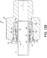
- the fitting assembly 350 may be but need not be similar or the same as the embodiment of Figs. 11A-11I above. In the illustrated embodiment of Figs. 12A and 12B , however, we omit the retaining member 280.
- the fitting assembly may include the retainer 270 having the ball carrier 272, the conduit gripping devices or balls 274, the biasing member 276 and the gland 278. Since we do not use the retaining member 280 in this embodiment, the gland 278 does not need to have the outer groove 290. Therefore, the retainer 270 is not held together as a subassembly with the second fitting component 352, which may be a male threaded nut.
- conduit may alternatively have a groove or recess formed in the outer surface of the conduit wall at an axial position that aligns with the conduit gripping members such as the spherical balls.
- the groove or recess can in some applications enhance the conduit grip by the conduit gripping members because the balls will not have to be forced to indent into the conduit surface. Engagement of the conduit gripping members with the conduit groove may also provide a detectable positive indication of full insertion or installation of the conduit in the fitting assembly.
Landscapes
- Engineering & Computer Science (AREA)
- General Engineering & Computer Science (AREA)
- Mechanical Engineering (AREA)
- Quick-Acting Or Multi-Walled Pipe Joints (AREA)
Description
- This application claims priority to and all benefit of
U.S. Provisional Patent Application Serial No. 62/252,465, filed on April 23, 2016 - The inventions relate generally to fittings for conduits such as tube and pipe. More particularly, the inventions relate to fittings that provide single action push to connect operation.
EP0735306 discloses a pipe coupling providing, within a socket to receive a pipe end, a grab ring for engagement with the inserted pipe end.EP2163802 discloses a connector assembly having a base body including an inner body and a case.EP0156575 discloses a clamp or connector for an elongated member, such as a pipe, that has a body providing an internal bore having axially spaced inclined surfaces that are respectively engageable by sets of angularly spaced balls supported in apertures in a cylindrical cage biased axially by a spring.GB2325718 WO02/29301 - According to the present invention, there is provided a push to connect fitting assembly according to
claim 1. Further preferred embodiments are defined in the dependent claims. - A first inventive concept described herein is a fitting assembly for a conduit, for example tube or pipe, in which a single action on the conduit can be used to achieve a fluid tight seal and retention of the conduit without need for subsequent action or motion. In an exemplary embodiment, a conduit can optionally be hand held or otherwise inserted into a first end of the fitting assembly so as to engage a seal device and a conduit gripping member with a single action on the conduit to achieve a fluid tight seal and retention of the conduit by the conduit gripping member. No subsequent action is needed such as rotation, tightening or clamping of the fitting components. This embodiment may also be referred to herein as a single action push to connect fitting. Additional embodiments are described herein.
- According to an exemplary aspect of the present application, a fitting assembly is disclosed for conduit such as tube or pipe in which a single action on the conduit can be used to achieve a fluid tight seal and retention of the conduit without need for subsequent action or motion. The fitting assembly includes a retainer that grips the conduit, and further the retainer includes a colleting feature that reduces or minimizes conduit vibration and rotary flex that may otherwise adversely affect performance of the fitting assembly. Additional embodiments are described herein.
- In an exemplary embodiment, a push to connect fitting assembly includes first and second fitting components, a seal device, and a retainer. The first fitting component has an outboard end that is adapted to receive a conduit end. The second fitting component is joined to the first fitting component to define an interior cavity. The seal device is disposed in the interior cavity, and seals one of the first and second fitting components with an outer surface of a conduit end when the conduit end is inserted into the outboard end of the first fitting component. The retainer is assembled with at least one of the first and second fitting components, and includes a gripping portion that engages the inserted conduit end over a first surface contact area to grip the conduit end, and a colleting portion outboard of the gripping portion. The colleting portion engages the inserted conduit over a second surface contact area greater than the first surface contact area to collet the inserted conduit end.
- In another exemplary embodiment, a push to connect fitting assembly includes first and second fitting components, a seal device, and a retainer. The first fitting component has an outboard end that is adapted to receive a conduit end. The second fitting component is joined to the first fitting
- In an exemplary embodiment, a push to connect fitting assembly includes first and second fitting components, a seal device, and a retainer. The first fitting component has an outboard end that is adapted to receive a conduit end. The second fitting component is joined to the first fitting component to define an interior cavity. The seal device is disposed in the interior cavity, and seals one of the first and second fitting components with an outer surface of a conduit end when the conduit end is inserted into the outboard end of the first fitting component. The retainer is assembled with at least one of the first and second fitting components, and includes a gripping portion that engages the inserted conduit end over a first surface contact area to grip the conduit end, and a colleting portion outboard of the gripping portion. The colleting portion engages the inserted conduit over a second surface contact area greater than the first surface contact area to collet the inserted conduit end.
- In another exemplary embodiment, a push to connect fitting assembly includes first and second fitting components, a seal device, and a retainer. The first fitting component has an outboard end that is adapted to receive a conduit end. The second fitting component is joined to the first fitting component to define an interior cavity. The seal device is disposed in the interior cavity, and seals one of the first and second fitting components with an outer surface of a conduit end when the conduit end is inserted into the outboard end of the first fitting component. The retainer is assembled with at least one of the first and second fitting components, and includes a gripping portion comprising a plurality of circumferentially spaced bearing members that grip the inserted conduit end, and a colleting portion outboard of the gripping portion, wherein the colleting portion collets the inserted conduit end
- In another exemplary embodiment, a push to connect fitting assembly includes first and second fitting components, a seal device, and a retainer. The first fitting component has an outboard end that is adapted to receive a conduit end. The second fitting component is joined to the first fitting component to define an interior cavity. The seal device is disposed in the interior cavity, and seals one of the first and second fitting components with an outer surface of a conduit end when the conduit end is inserted into the outboard end of the first fitting component. The retainer is assembled with the second fitting component, and includes a gripping portion and a colleting portion outboard of the gripping portion. The gripping portion is spring biased radially inward toward gripping engagement with the inserted conduit end, and the colleting portion is spring biased radially inward toward colleting engagement with the inserted conduit end.
- In another exemplary embodiment, a push to connect fitting assembly includes first and second fitting components, a seal device, and a retainer. The first fitting component has an outboard end that is adapted to receive a conduit end. The second fitting component is joined to the first fitting component to define an interior cavity. The seal device is disposed in the interior cavity, and seals one of the first and second fitting components with an outer surface of a conduit end when the conduit end is inserted into the outboard end of the first fitting component. The retainer is assembled with the second fitting component, and includes a gripping portion and a colleting portion outboard of the gripping portion. The gripping portion is biased against a first portion of a continuously tapered interior surface of the fitting assembly to grip the inserted conduit end, and the colleting portion is biased against a second portion of the continuously tapered interior surface of the fitting assembly to collet the inserted conduit end.
- In another exemplary embodiment, a push to connect fitting assembly includes first and second fitting components, a seal device, and a retainer. The first fitting component has an outboard end that is adapted to receive a conduit end. The second fitting component is joined to the first fitting component to define an interior cavity. The seal device is disposed in the interior cavity, and seals one of the first and second fitting components with an outer surface of a conduit end when the conduit end is inserted into the outboard end of the first fitting component. The retainer is assembled with the second fitting component, and includes a gripping portion and a colleting portion outboard of the gripping portion. When the conduit end is inserted into the outboard end of the first fitting component and a fluid pressure is applied to the fitting assembly, the seal device is pressurized to apply a biasing force to the gripping portion to bias the gripping portion toward gripping engagement with the inserted conduit end and to the colleting portion to bias the colleting portion toward colleting engagement with the inserted conduit end.
- In another exemplary embodiment, a push to connect fitting assembly includes first and second fitting components, a seal device, and a retainer. The first fitting component has an outboard end that is adapted to receive a conduit end. The second fitting component is joined to the first fitting component to define an interior cavity. The seal device is disposed in the interior cavity, and seals one of the first and second fitting components with an outer surface of a conduit end when the conduit end is inserted into the outboard end of the first fitting component. The retainer is assembled with at least one of the first and second fitting components, the retainer including a gripping portion that grips the inserted conduit end, and a colleting portion outboard of the gripping portion, the colleting portion including at least one axially extending, radially flexible member having an end portion adapted to be flexed into engagement with the outer surface of the inserted conduit end to collet the inserted conduit end.
- In another exemplary embodiment, a push to connect fitting assembly is provided in combination with a conduit having a longitudinal axis. The fitting assembly includes first and second fitting components, a seal device, and a retainer. The first fitting component has an outboard end that is adapted to receive an end portion of the conduit. The second fitting component is joined to the first fitting component to define an interior cavity. The seal device is disposed in the interior cavity, and seals one of the first and second fitting components with a first outer surface of the conduit end portion when the conduit end portion is inserted into the outboard end of the first fitting component. The retainer is assembled with at least one of the first and second fitting components, and includes a gripping portion comprising a plurality of circumferentially spaced bearing members that grip a second outer surface of the inserted conduit end portion, and a colleting portion outboard of the gripping portion, wherein the colleting portion collets a third outer surface of the inserted conduit end portion.
- According to another aspect of the present application, a fitting assembly is disclosed for conduit such as tube or pipe in which a single action on the conduit can be used to achieve a fluid tight seal and retention of the conduit without need for subsequent action or motion is disclosed. The fitting assembly includes a seal device that forms a non-polymeric seal between one of the first and second fitting components and an outer surface of a conduit when the conduit is inserted into the outboard end of the first fitting component. Additional embodiments are described herein.
- In another exemplary embodiment, a push to connect fitting assembly includes first and second fitting components, a seal device, and a retainer. The first fitting component has an outboard end that is adapted to receive a conduit end. The second fitting component is joined to the first fitting component to define an interior cavity. The seal device is disposed in the interior cavity, and forms a non-polymeric seal between one of the first and second fitting components and an outer surface of a conduit end when the conduit end is inserted into the outboard end of the first fitting component. The retainer is assembled with at least one of the first and second fitting components, the retainer including a gripping portion that grips the conduit end when the conduit end is inserted into the outboard end of the first fitting component.
- These and additional aspects and embodiments of the inventions will be understood by those skilled in the art from the following detailed description of the exemplary embodiments in view of the accompanying drawings.
-
-
Fig. 1 is an isometric end view of an exemplary embodiment not according to the present invention of a fitting assembly with a conduit fully inserted, -
Fig. 2 is the fitting assembly ofclaim 1 in longitudinal section, -
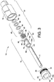
Fig. 3 is an exploded isometric of the fitting assembly ofFig. 1 including the conduit, -
Fig. 4 is an embodiment of a first fitting component subassembly that may be used in the embodiment ofFigs. 1-3 in longitudinal section, -
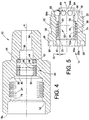
Fig. 5 is an embodiment of a second fitting component subassembly that may be used in the embodiment ofFigs. 1-3 in longitudinal section, -
Fig. 6 is the fitting assembly ofFig. 2 shown in longitudinal section prior to insertion of the conduit C into the fitting assembly, -
Fig. 7 is the fitting assembly ofFig. 2 shown in longitudinal section with partial insertion of the conduit C into the fitting assembly, -
Fig. 8 is another exemplary embodiment of a fitting assembly in longitudinal section, -
Fig. 9 is an exploded isometric of the fitting assembly ofFig. 8 including the conduit, -
Figs. 10A-10F illustrate other exemplary embodiments of a single action push to connect fitting assembly including a colleting feature, -
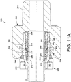
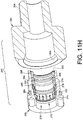
Figs. 11A-11I illustrate other exemplary embodiments of a single action push to connect fitting assembly including a colleting feature, -
Fig. 12A-12B illustrate another exemplary embodiment of a single action push to connect fitting assembly including a colleting feature and an all metal configuration, -
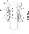
Figs. 13A-13C illustrate another exemplary embodiment of a single action push to connect fitting assembly including a colleting feature, with the fitting assembly having a male configuration, and -
Figs. 14A and 14B illustrate an exemplary alternative structure for a ball carrier. - Herein, the terms fitting and fitting assembly are used interchangeably. In various exemplary embodiments, a fitting assembly structure as taught herein is separately claimed as an invention without requiring the conduit to be part of the fitting assembly, and further without requiring that the various parts be in a fully assembled condition (such as may be the case, for example, of the assembly parts being shipped from a manufacturer or distributor.) In at least one embodiment, a fitting assembly includes a first fitting component or subassembly having a seal device and a second fitting component or subassembly having a retainer. In any of the embodiments described herein, the conduit does not require treatment or modification from stock condition, although optionally such may be done if needed in particular applications. For example, it is common for the conduit end to be cut substantially perpendicular to the conduit longitudinal axis and deburred as needed, but even these common steps are optional and not required to achieve conduit grip and fluid tight seal. By stock condition is meant that the conduit may be a conventional hollow right cylinder having a cylindrical inner surface that may be exposed to fluid (for example, liquid, gas or other flowable material) contained by the conduit, and a cylindrical outer surface, with a wall thickness defined as the difference between the inner diameter and the outer diameter of the conduit. The conduit may be made of any material, is preferably metal, and more preferably is a stainless steel alloy, but the inventions are not limited to these exemplary materials and other alternative materials may be used as needed for particular applications. Although traditional hollow cylindrical conduits are preferred, other conduit shapes and geometry may alternatively be used for either the outer wall or inner wall or both walls of the conduit. The word conduit herein refers to traditional tube and pipe but also includes other hollow fluid carrying structures that might be referred to by another word other than tube or pipe.
- We also use the terms inboard and outboard for reference purposes only. By inboard we mean towards the center or closed end of the fitting assembly or fitting component along the reference axis, and by outboard we mean away from the center or towards the open end of the fitting assembly or fitting component along the reference axis.
- With reference to
Figs. 1-3 , an embodiment not according to the present invention of afitting assembly 10 is represented. The exemplaryfitting assembly 10 provides for or allows single action push to connect operation. By single action is meant that a conduit C, and in particular the end portion C1 of the conduit end C, can be inserted into thefitting assembly 10 with a single dimensional or directional movement or action, and when fully inserted the conduit C is sealed against fluid pressure and is retained in position. The axial insertion may be performed manually or by a tool or machine. By push to connect is meant that the single action may be a simple axial movement or push along the longitudinal axis of the conduit C and that this single action is the only action needed to complete the mechanical connection between the conduit C and thefitting assembly 10. No subsequent or additional motion or action is needed to complete the mechanical connection and fluid tight seal. In an exemplary embodiment, the single directional action or movement is an axial movement along a longitudinal axis of the conduit C. No other or additional or subsequent manual or tool action or movement of thefitting assembly 10 components is needed to achieve conduit seal and retention. Thus, a single action push to connect fitting is distinguished from a traditional fitting assembly that typically is pulled-up or tightened to effect conduit grip and seal by relative movement of the fitting assembly components after insertion of the conduit; for example, a body and a nut that are joined by a threaded mechanical connection and pulled-up by relative rotation of the body and nut, or by being clamped together without a threaded mechanical connection. - Herein, the terms axis or axial and derivative forms thereof refer to a longitudinal axis X along which a conduit C will be inserted and retained. Reference to radial and radial direction and derivative terms also are relative to the X axis unless otherwise noted. In the illustrated embodiments, the axis X may be the central longitudinal axis of the conduit C which also may but need not correspond with or be coaxial with the central longitudinal axis of the
fitting assembly 10. The conduit C may be any conduit that defines a flow path FP for system fluid that is contained by the conduit C and the fitting 10. The inventions and embodiments described herein are particularly suitable for metal conduit such as metal pipe or tube, however, non-metal conduits may also be used as needed. The conduit C may have any range of diameter size, for example, 1/16th inch or less to 3 inches or greater in diameter and may be in metric or fractional sizes. The conduit C may also have any range of wall thickness that allows for an axial insertion into thefitting assembly 10. - The
fitting assembly 10 may include two discrete sections or subassemblies. In an embodiment, thefitting assembly 10 may include a first fitting component orsubassembly 12 and a second or fitting component orsubassembly 14. The firstfitting component 12 and the secondfitting component 14 may be joinable or mate together in any manner suitable for the application or use of thefitting assembly 10. For example, the firstfitting component 12 and the secondfitting component 14 may be joinable together using a threaded mechanical connection 16 (Fig. 2 .) Many other mechanical connections may alternatively be used, including but not limited to a clamped connection or bolted connection or crimped connection, to name three examples, or non-mechanical connections may be used, for example, a weldment. - Note that although the conduit C is shown in
Fig. 3 , the conduit C is not considered to be part of the secondfitting component 14. -
Figs. 1-3 illustrate thefitting assembly 10 in a fully assembled condition, and further with the conduit C fully inserted or seated in thefitting assembly 10. In this position, the conduit C is sealed and retained in position, especially against fluid pressure, although thefitting assembly 10 may be used in low or zero or negative pressure applications. - With additional reference to
Figs. 4 and 5 , the firstfitting component 12 may be realized as a body subassembly. The first fitting component may include abody 18 that is adapted to receive the conduit end C1. Although it is common to call the conduit receiving fitting component a body in fitting terminology, the firstfitting component 12 may use a fitting component other than what might be considered a fitting body. Also, thebody 18 need not be a standalone component, but alternatively may be formed as a cavity in a block, for example a manifold or a valve body to name a couple of examples. Such body embodiments are commonly known in the art as a port or a ported fitting. - The second
fitting component 14 may be realized as a nut subassembly. The secondfitting component 14 may include anut 20 through which the conduit end C1 passes into thebody 18. Although it is common to call the mating second fitting component 14 a nut in fitting terminology, the secondfitting component 14 may be a fitting component other than what might be considered a fitting nut. - Although the exemplary embodiment illustrates a male threaded
nut 20 havingmale threads 22 and a female threadedbody 18 having matingfemale threads 24, an alternative would be to have thenut 20 be female threaded and thebody 18 be male threaded. And as noted above, thebody 18 and thenut 20 may be joinable by many different techniques, including a mechanical connection other than a threadedmechanical connection 16. Moreover, thebody 18 and thenut 20 may be made of any suitable material, for example stainless steel or other metal, or may be made of non-metals, for example plastics or polymers or composite materials or other suitable materials, as needed. For embodiments in which the conduit C is stainless steel or other metal, thebody 12 and thenut 14 are preferably made of metal and more preferably stainless steel alloy. Also, in additional embodiments, thebody 12 and thenut 14 are preferably all metal. - The
nut 20 may include two or more pin holes 26 that can be used to receive a tool that is used to drive thenut 20 into thebody 18, for example by rotation of thenut 20 relative to thebody 18 about the axis X. It will be noted that the axial dimension of thenut 20 may be selected so that theoutboard end 20a of thenut 20 appears flush with theoutboard end surface 18a of thebody 18, when thenut 20 is fully tightened, but this flush arrangement is optional. Thenut 20 may also include aflange 28 having anend surface 30 that engages afirst counterbore surface 32 in thebody 18. This engagement between thenut end surface 30 and the bodyfirst counterbore surface 32 provides a positive stop to further tightening of thenut 20 relative to thebody 18 thereby preventing over-tightening. As best viewed inFig. 1 , thebody 18 may includewrench flats 34, for example hex flats, to assist in tightening thebody 18 and thenut 20 together when a threaded mechanical connection is used. - The
body 18 may include an optional second counterbore orsocket 36 that is adapted to receive the conduit end C1. Thesecond counterbore 36 of thebody 18 may be used as a positive stop during insertion of the conduit C into thefitting assembly 10 so that the assembler can sense that the conduit C is preferably fully inserted and seated against thecounterbore 36 shoulder (seeFig. 2 .) However, many other techniques may alternatively be used to control or delimit the axial distance that the conduit C is inserted into thefitting assembly 10. Thebody 18 may include a flow passage or bore 38 for fluid that passes through the conduit C and thefitting assembly 10. Alternatively, thebody 18 may be formed as a cap or plug with theflow passage 38 omitted. - The
body 18 andnut 20 together define an interior cavity that retains aseal device 40 that establishes a fluid tight seal against fluid pressure between the outer surface of the conduit C and thebody 18 when the conduit is inserted into the outboard end of the fitting body. Thebody 18 may include athird counterbore 42 that delimits a socket that receives theseal device 40, and as such thebody 18 and theseal device 40 form the firstfitting component 12. Thethird counterbore 42 helps to retain theseal device 40 in position when the conduit C is inserted into thefitting assembly 10. Theseal device 40 may comprise a single seal member or alternatively multiple seal members as shown inFigs. 2 ,3 and4 . For example, theseal device 40 may include aprimary seal member 44 such as, for example, an elastomeric o-ring style seal. Many different primary seal member designs and materials may alternatively be used, including but not limited to a halogen polymer (for example, PTFE), carbon (for example, expanded graphite), soft metal (for example, silver), spring metal (for example, X750, 17-4PH.) Theseal device 40 may further include one or more optional backing rings 46, 48 which may be used as needed to help reduce extrusion of the softerprimary seal 44 under pressure. The backing rings 46, 48 may be made of a harder plastic material, for example PTFE or PEEK as compared to theprimary seal member 44. Anoptional gland 50, which may be metal or other suitable material as needed, may be used to reduce or prevent damage to theseal device 40 due to contact with a retainer (described below) and also to help retain theseal device 40 in position as part of the firstfitting component 12. Theprimary seal member 44 provides a fluid tight seal for the fitting 10 by being compressed against the outer surface of the conduit C and one or more surfaces of thethird counterbore 42 or socket in which theseal member 44 is disposed within thebody 18. Theseal device 44 therefore provides a primary body seal to contain fluid within the fitting 10 so as to prevent fluid that is in the conduit C from escaping to the ambient or surrounding environment. The body seal and the conduit seal are effected when the conduit C has been inserted axially into thebody 12 sufficiently so as to pass through theprimary seal member 44. - The
fitting components retainer 52 operable to grip and lock or otherwise retain the conduit C with fitting assembly when the conduit C has been sufficiently inserted axially into thefitting assembly 10 so as to engage theretainer 52. It will be noted from the following description that theretainer 52 can grip and retain the conduit C with thenut 20 at an axial position that is less than a full insertion used to achieve conduit seal by theseal device 40. The conduit C can optionally even be retained with thenut 20 when thenut 20 has not been assembled to thebody 18. - In an embodiment (see
Fig. 5 ) theretainer 52 may be a subassembly comprising a retainer body 54 (e.g., a ball cage or carrier), at least one conduit gripping member or bearingmember 56 and a biasingmember 58. Although theball cage 54 and theconduit gripping member 56 are shown as two distinct parts, alternatively other retainer designs may be used that would integrate this functionality into a single part, further optionally including the functionality of the biasingmember 58. Theconduit gripping member 56 may be realized in the form of one or more substantiallyspherical balls 56, although other conduit gripping member shapes and designs may alternatively be used as needed. InFig. 5 theconduit gripping member 56 appears to be displaced out of contact with theball cage 54 even though there is no conduit itFig. 5 . This is done for clarity and understanding of the structure. Those skilled in the art will readily understand that when the conduit C is not positioned in theretainer 52 theballs 56 drop partially into theball cavities 64 as explained further below. -
Figs. 4 and 5 thus illustrate an embodiment in which the firstfitting component 12 is a standalone subassembly and the secondfitting component 14 is also a standalone subassembly. The firstfitting component 12 and the secondfitting component 14 when assembled or joined together thus provide or form thefitting assembly 10. Thefitting assembly 10 therefore is a simple two part assembly which can simplify assembly and use in the field. The firstfitting component 12 and the secondfitting component 14 may be assembled together at the manufacturer, a distributor or by the end user. After the firstfitting component 12 and the secondfitting component 14 have been assembled together, thefitting assembly 10 provides a complete single action push to connect fitting by which all that is needed to make a mechanical connection with a conduit end, as well as seal the conduit end against fluid pressure, is to push the conduit end into thefitting assembly 10 until the conduit end preferably bottoms against thesecond counterbore 36 or alternatively is axially inserted into the fitting assembly so that theseal device 40 engages with the outer surface of the conduit C. The conduit C may be inserted manually or alternatively by use of a tool or a machine or other convenient means. Insertion of the conduit C into thefitting assembly 10 makes the mechanical connection and the fluid tight seal between the conduit C and thefitting assembly 10 without any required subsequent or further or additional action or motion. - The
ball cage 54 may be adapted to move or shift axially within acentral bore 60 of thenut 20. Theball cage 54 includes a throughbore 62 that preferably is at least cylindrical partially admits insertion of the conduit C into the fitting assembly 10 (Fig. 2 ) with a preferably close fit. Aninward end portion 54b of theball cage 54 includes one ormore ball cavities 64 that position or trap theballs 56 within a preferably taperedwall cavity 66 of thenut 20. The taperedwall cavity 66 of thenut 20 is delimited by atapered wall 66a that preferably is frusto-conical, but alternatively other geometric shapes and forms may be used as needed. Note that inFig. 5 as well asFigs. 2 and8 for clarity we only show oneball 56, but in practice there may be aball 56 in eachball cavity 64 orfewer balls 56 may be used, although preferably there will be at least three balls used. Eachball cavity 64 may include a beveled or shaped ball cavity wall orsurface 68 that may be sized and beveled or shaped to prevent the associatedball 56 from falling through theball cavity 64. However, eachball cavity 64 is preferably sized so that at least a portion of eachball 56 protrudes through the associatedball cavity 64 so as to make contact with the conduit C outer surface (seeFigs. 2 and6 ). - The
balls 56 may be made of any suitable material as needed, preferably made of metal especially when used with a metal conduit C, and more preferably made of stainless steel. - The
central bore 60 of thenut 20 may include a radially inward projectingrib 70 and theoutboard end 54a of theball cage 54 may include a radially outwardly projectingflange 72 that presents aninner surface 72a that faces towards therib 70. Theflange 72 and therib 70 along with thecentral bore 60 of thenut 20 define apocket 74 that receives the biasingmember 58. The biasingmember 58 may be realized in the form of a coiled spring as shown, however, many other types of biasing members may alternatively be used. The spring or biasingmember 58 is compressed in thepocket 74 so as to apply an outwardly directed axial force on theball cage 54. By outwardly is meant in an axial direction away from the conduit end C1. Theball cage 54 is able to move or shift axially although the movement or shift may be slight and perhaps imperceptible by visual or tactile feedback. The axial bias produced by thespring 58 forces theballs 56 that sit in theball cavities 64 in towards the radially narrower portion of the taperedwall cavity 66 such that theballs 56 engage thetapered wall 66a and are trapped against thetapered wall 66a because of the limited radial movement permitted by the ball cavities 64. The trappedballs 56 thus also prevent thespring 58 from pushing theball cage 54 out through the nutcentral bore 60. - It will be noted that the amount of axial movement or shift of the
ball cage 54 will be a function of a number of design factors including the size of theballs 56 relative to the size of the taperedwall cavity 66. The biasingmember 58 thus serves to maintain theretainer 52 with thenut 20 as a complete subassembly of the secondfitting component 14. Also note that inFig. 2 (as well asFig. 8 ) thespherical ball 56 is shown centered in therespective ball cavity 64, but this is an artifact of the drawing model. In practice, the biasingmember 58 axially biases theball cage 54 outwardly so as to wedge theballs 56 between thetapered wall 66a and the outer surface of the conduit C. Theballs 56 therefore would be in contact with the forward or inward portion of the ball cavity wall orsurface 68 that delimits theball cavity 64. - With reference to
Figs. 6 and7 , as the conduit C is inserted into thefitting assembly 10, the conduit end C1 will contact or engage theballs 56 which partially protrude through the ball cavities 64. The initial contact of the conduit end C1 with theballs 56 is shown inFig. 7 . As the conduit end C1 is further inserted, theballs 56 and theball cage 54 are moved or shifted axially inward against the force of thespring 58 so that theballs 56 can be radially displaced further (by a rolling action of theballs 56 on the outer surface of the conduit C) into theball cavities 64 and thetapered wall cavity 66 so as to allow the conduit end C1 to be fully inserted into thesecond counterbore 36 of thebody 18. This movement occurs due to frictional engagement between theballs 56 and the conduit end C1 outer surface. This same frictional engagement helps to prevent the conduit C from simply being pulled out once it has engaged with theballs 56. The conduit end C1 may include a chamfer (84 inFig. 2 ) to facilitate initial contact with theballs 56. The amount of axial and radial shift or movement of theballs 56 may typically be rather small and just enough so as to allow the conduit end to be inserted fully. All that is needed is enough movement to release load of theballs 56 against the conduit so that the conduit freely slides into the fitting 10. Conduit insertion may be done by any convenient means or technique, including but not limited to hand-held manual insertion, use of a tool to assist with manual insertion or machine insertion. - When the conduit C has been fully inserted into the
second counterbore 36 of thebody 18 as represented inFig. 2 , theretainer 52 has an axial position within thenut 14 such that theballs 56 are in contact with the conduit C and thetapered wall 66a due to the bias of thespring 58. We refer to this axial position of theretainer 52 to be the first axial position within or relative to thefitting assembly 10 and that is the axial position for gripping and retaining the conduit C in thefitting assembly 10 to constrain the conduit C from axial withdrawal from the conduit fitting 10. Thus, theballs 56 are wedged and trapped and cannot move radially or axially, thereby exerting a retaining force and tight grip on the conduit C. The biasingmember 58 maintains theballs 56 in contact with thetapered wall 66a and the conduit C outer surface, thereby applying a retaining force or load against the conduit C to resist axial withdrawal of the conduit C from the fitting 10. Theballs 56 resist axial withdrawal of the conduit C from theball cage 54 and the more force that is applied to the conduit C to pull it out the stronger is the gripping force and retention due to the wedging action of theballs 56 trapped between the conduit C outer surface and thetapered wall 66a. The friction and radial load between theballs 56 and the conduit outer surface prevents axial movement of the conduit back out of the fitting 10 and this load will increase if an axial force is applied to the conduit C to try to pull the conduit C back out of the fitting 10. Note that the conduit C is trapped in this position in theball cage 54 even if thenut 14 is not installed in the body 18 (although in that circumstance the conduit can be pushed forward but not pulled rearward, and thespring 58 will prevent the conduit C and theball cage 54 from falling apart.) - Note also that fluid pressure, from system or working fluid in the conduit C, acting on the seal device 40 (with or without the optional gland 50) and/or an end face of the conduit end C1 will tend to increase axial forces against either the
ball cage 54 or the conduit C or both towards the reduced sized portion of the taperedwall cavity 66. These axial forces due to fluid pressure will tend to further increase the compression of theballs 56 against thetapered wall 66a, thus also increasing the grip and retention of the conduit C by theballs 56. It is contemplated that theballs 56 may comprise a harder material than the conduit C so that theballs 56 may actually indent into the outer surface of the conduit C, further increasing resistance to the conduit C being axially withdrawn or forced out of the fitting 10. - However, the conduit C can be easily withdrawn or pulled out of the
retainer 52, for example the ball cage orretainer body 54, by simply applying an axially inward force against theball cage 54 and the biasing force of thespring 58, for example, by pushing against theflange 72 such as by applying a force against theoutboard end 54a of the ball cage. By pushing on theball cage 54 against the force of thespring 58, theball cage 54 can be moved or shifted axially forward (as viewed inFig. 2 ) to another axial position within thefitting assembly 10 at which the compression on the trappedballs 56 against the conduit C is reduced enough so that the conduit C can be axially withdrawn or removed from thefitting assembly 10. We refer to this axial position of theretainer 52, that is sufficient to reduce the compression on the trappedballs 56 to allow withdrawal of the conduit C, as the second axial position of theretainer 52 within thefitting assembly 10. Again, this movement or shift of theretainer 52 may be slight so as to release the stress on theballs 56. Thus, the retaining force of theballs 56 against the conduit C is lessened and the conduit C will easily slide back out of thefitting assembly 10. The fitting 10 design also allows of repeated re-use, also known as remake, of the fitting, either with the same conduit or a different conduit. - An axially inward force may be applied against the
flange 72 of theball cage 54 either manually such as with fingers or optionally with a tool (not shown). FromFig. 2 it will be noted that an embodiment of theball cage 54 has theoutboard end 54a axially recessed in thenut 20. If the recess is deep, a tool might be used to push on theball cage 54. Alternatively, the recess may be shallow enough that fingers or a tool could be used to push on theoutboard end 54a. As another alternative, theball cage 54 may be axially sized so as to position theoutboard end 54a either flush, about flush or slightly outside of thenut 20, in any case making it easier to contact theball cage 54 with a tool or fingers to displace theball cage 54 so that the conduit C can be withdrawn. Preferably, fluid pressure will be reduced to ambient pressure before theretainer 52 is acted on to allow the conduit C to be withdrawn. - Note further that although preferably the conduit gripping portion, whether in the form of one or more spherical balls or other form, becomes wedged or trapped between the conduit C outer surface and a preferably tapered
surface 66a, other surface geometries or additional components may be used that compress theconduit gripping device 56 against the conduit C to constrain axial withdrawal of the conduit C. It is preferred, whatever technique or structure is used to constrain the conduit C in thefitting assembly 10, that there be a first position and a second position, that can be selected from outside the assembled fitting 10 (for example in the exemplary embodiment pushing theretainer 52 to the second axial position), to release the conduit C for withdrawal from thefitting assembly 10, without necessarily having to loosen or separate the firstfitting component 12 and the secondfitting component 14. - Note from
Fig. 2 that when theball cage 54 is pushed inward against the force of thespring 58, the distal end of theball cage 54 could contact theoptional gland 50, so thatgland 50 helps protect against damage to theseal device 40 in such an event. - An outwardly extending
portion 76 of theball cage 54 inner diameter throughbore 62 optionally may be outwardly tapered so as not to apply stress to the conduit C (which can cause fretting) when possible system vibration may impart rotary flex or oscillation of the conduit C. The taper angle α and the length of the taperedportion 76 need only be large enough to reduce or prevent stress being applied to the conduit C by theball cage 54. This will cause the stress from conduit oscillation or vibration to be concentrated more at theballs 56. - The ball cavities 64 and the
balls 56 may be evenly spaced circumferentially from each other in theball cage 54 so as to further reduce potential damage to the conduit caused by vibration and oscillation of the conduit. An even or uneven number ofballs 56 may be used. A benefit of an uneven number ofballs 56 is that no two balls will be diametrically opposed to each other when theballs 56 are in position in theball cage 54. - With reference to
Figs. 2 and5 , thebody 18 includes a partially threadedcylindrical bore 78 in which the female threads 24 (Fig. 4 ) may be formed. This bore 78 may include afourth counterbore 80 with atapered shoulder 82. Thistapered shoulder 82 may be used to provide additional space for movement of theballs 56 when theball cage 54 is axially shifted to allow a retained conduit C to be removed. Note also that the conduit end C1 may include thechamfer 84 to reduce or prevent damage to theseal device 40 when the conduit C is inserted into thefitting assembly 10. - Further note that preferably but not necessarily the
seal device 40 is axially disposed between the conduit end C1, which is the fluid pressure head, and theretainer 52, with the conduit C being inserted from the retainer side of thefitting assembly 10. In other words, during assembly the conduit C is inserted into thefitting assembly 10 preferably from the axially outward side or end of the retainer 52 (from the left as viewed inFigs. 2 ,6 and7 ) and passes through the axially opposite side or end of theretainer 52 before the conduit end C1 engages with or passes through theseal device 40. The conduit therefore is inserted into thefitting assembly 10 preferably from the biasing member side of theretainer 52. This allows easier assembly and retention of theseal device 40 with thefitting body 18 as a subassembly and also helps reduce or prevent system fluid wetting of theretainer 52, for example, thespring 58. -
Figs. 8 and9 illustrate another embodiment of a single action push to connect conduit fitting 10'. In this embodiment, most of the components and parts of the fitting 10' may be but need not be the same as the embodiment ofFigs. 1-7 above. Therefore, like reference numerals are used for like parts and the description of the parts need not be repeated. Note again that although the conduit C is shown inFig. 9 , the conduit C is not considered to be part of the secondfitting component 14. - The embodiment of
Figs. 8 and9 differs from the embodiments described above in the design of theretainer 90. In an embodiment, theretainer 90 may be a subassembly comprising a ball cage orannular retainer body 92, a conduit gripping portion (e.g., one or more conduit gripping members 94) and a biasingmember 58. Although theretainer body 92 and the conduit gripping portion are shown as two distinct parts, alternatively other retainer designs may be used that would integrate this functionality into a single part, further optionally including the functionality of the biasingmember 58. The conduit gripping portion may be realized in the form of a first set of one or more preferablyspherical balls 94, although other conduit gripping member or bearing member designs may alternatively be used as needed. Theretainer body 92 may be adapted to move or shift axially within acentral bore 60 of thenut 20. Theretainer body 92 includes a throughbore 96 that admits insertion of the conduit C into the fitting assembly 10'. Aninward end portion 92b of theretainer body 92 includes one or more ball cavities 98 that position or capture theballs 94 within a preferably taperedwall cavity 66 of thenut 20, between the nut and the retainer body. Note that inFig. 8 and9 for clarity we only show one conduit gripping member orball 94, but in practice there may be aball 94 in each ball cavity 98 orfewer balls 94 may be used, although preferably there will be at least three balls used. Each ball cavity 98 may include a beveled or shapedball cavity wall 100 that may be sized and beveled or shaped to prevent the associatedball 94 from falling through the ball cavity 98. However, each ball cavity 98 is preferably sized so that at least a portion of eachball 94 protrudes through the associated ball cavity 98 so as to make contact with the conduit C outer surface. - The
central bore 60 of thenut 20 may include a radially inward projectingrib 70 and theoutboard end 92a of theretainer body 92 may include a radially outwardly projectingflange 102 that presents aninner surface 102a that faces towards therib 70. Theflange 102 and therib 70 along with thecentral bore 60 of thenut 20 define anannular pocket 74 that receives the biasingmember 58. The biasingmember 58 may be realized in the form of a coiled spring as shown, however, many other types of biasing members may alternatively be used. The spring or biasingmember 58 is compressed in thepocket 74 so as to apply an outwardly directed axial force on theretainer body 92. By outwardly is meant in an axial direction away from the conduit end C1, towards the outboard ends of the body and nut. Theretainer body 92 is able to move or shift axially although the movement or shift may be slight and perhaps imperceptible by visual or tactile feedback. The axial bias produced by thespring 58 forces theballs 94 that sit in the ball cavities 98 axially outward towards the radially narrower portion of the taperedwall cavity 66 such that theballs 94 engage thetapered wall 66a and are forced radially inward and trapped against thetapered wall 66a because of the limited radial movement permitted by the ball cavities 98. The trappedballs 94 thus also prevent thespring 58 from pushing theretainer body 92 out through the nutcentral bore 60. - It will be noted that the amount of axial movement or shift of the
retainer body 92 will be a function of a number of design factors including the size of theballs 94 relative to the size of the taperedwall cavity 66. The biasingmember 58 thus serves to maintain theretainer 90 with thenut 20 as a complete subassembly of the secondfitting component 14, even when the nut is disassembled from the fitting body. - According to another aspect of the present application, a single action push to connect fitting assembly may be provided with a colleting portion or other such conduit engaging portion outboard of the gripping portion, for example, to collet or secure the conduit outboard of the gripping portion, thereby isolating the gripped portion of the conduit from flexure or vibration experienced by the conduit.
- In the exemplary embodiment, the
retainer 90 further includes a second set of bearing members. The exemplary bearing members are substantiallyspherical balls 104, although other shapes may be used as needed. The second set ofspherical balls 104 are preferably smaller in size than the first set ofspherical balls 94. Theretainer body 92 further includes a second set ofball cavities 106. The second set ofball cavities 106 and theballs 104 may be evenly spaced circumferentially from each other in theretainer body 92 so as to reduce potential damage to the conduit C caused by vibration and oscillation of the conduit. As with the first set ofballs 94 that used for gripping the conduit, an even or uneven number ofballs 104 may be used. A benefit of an uneven number ofballs 104 is that no two balls will be diametrically opposed to each other when theballs 104 are in position in theretainer body 92. - The second set of
balls 104 are preferably spaced axially outwardly from or outboard of the first set ofballs 94, with the second set ofballs 104 also trapped between thetapered wall 66a and the conduit C so as to add rigidity and stiffness to the support of the conduit C, somewhat akin to using two bearings spaced apart to support a rotating shaft. By having the second ball set 104 smaller in diameter than the first ball set 94, the same single uniform taperedwall 66 cavity may be used to retain (and radially inwardly bias) the ball sets and still have the second ball set 104 axially spaced from the first ball set 94. An alternative embodiment may use a non-uniformly (e.g., first and second portions tapered at different angles), but still continuously, tapered wall, or two discontinuous (i.e., separated by a non-tapered surface) tapered surfaces for the two ball sets, or other structures by which the second ball set 104 is trapped between thenut 20 and the conduit C. While the illustrated embodiments show the tapered wall surface as being defined entirely by the nut, in other embodiments (not shown), all or part of the tapered wall surface may be provided on a different fitting component. - The amount of axial separation provided between the first ball set 94 and the second ball set 104 will be based on various factors including but not limited to the loads that are expected on the conduit C and the amount of flex and vibration to which the conduit C may be exposed in use. The second ball set 104 is preferably axially spaced outwardly from the first ball set 94, in a direction away from the conduit end C1. Thus, the second ball set 104 helps to isolate the portion of the conduit gripped by the first ball set 94 from conduit vibration and rotary flex and other environmental stresses that the conduit C may experience during use. In order to help assure that the first ball set 94 provides sufficient conduit grip, the tolerances may be chosen so that during assembly and under the biasing influence of the biasing
member 58 on theretainer body 92, the first ball set 94 contacts thetapered wall 66a first or before the second ball set 104 would make such contact. The first ball set 94 indents slightly into the outer surface of the conduit C, which allows for enough axial shift of theretainer body 92 to allow the second ball set 104 to also make contact with thetapered wall 66a for radially inward biased engagement with the inserted conduit C. This indentation, retainer body shift, and second ball set conduit engagement may occur upon initial insertion of the conduit end into the fitting body (e.g., due to sufficient outboard biasing force from the biasing member 58). Alternatively, an additional or external outboard axial load on the fitting assembly (e.g., pulling force applied to the conduit, or an axial load applied by the pressurized seal device) may be necessary to indent the first set ofballs 94 into the conduit C sufficiently for second ball set 104 engagement with the conduit. - As an example, for conduit C,
nut 20 andballs 94 made of 316L stainless steel, and 6.35 mm (quarter-inch) nominal outer diameter conduit and nominal wall thickness of 0.889 mm (.035 in.), the first ball set 94 may indent into the conduit surface in the range of approximately 0.0762 mm (.003 in) to 0.1016 mm (.004 in) and up to approximately 0.2032 mm (.008 in). These numbers and ranges are exemplary of course because the actual numbers will be adjusted based on materials used for the retainer parts and the conduit, conduit wall thickness, diameters and so on. Theconduit gripping member 56 in the first embodiment (Figs. 1-7 ) and theconduit gripping member 94 of the second embodiment (Figs. 8 and9 ) may use this indentation feature into the conduit C outer surface to enhance the ability of theretainer 52/90 to grip and hold the conduit C over and above the friction forces that also work to retain the conduit C, advantageously when the conduit C is under pressure. For embodiments that use two ball sets, the second ball set 104 may also contribute to conduit grip by also indenting into the conduit C outer surface, although this is more likely to be the case under elevated pressures. Conduit grip by the second ball set 104 may be a benefit realized in some designs and applications, but the first ball set 94 preferably is designed to provide sufficient and primary conduit grip and retention, while the second ball set 104 preferably is designed to collet the conduit or to provide isolation of conduit vibration and flex from the first ball set 94. - From
Fig. 9 it will be noted that each ball cavity 98 may include an axially extending relief orgroove 108. During assembly of theretainer 90 into thenut 20, due to the limited axial movement of theretainer body 92 resulting from theflange 72 contacting the rib 70 (or from the flange and rib fully compressing the biasing member 58), it may be in some cases that theretainer body 92 can only extend just far enough to partially expose the ball cavities 98 to allow theballs 94 to be positioned into the ball cavities 98. The relief or groove 108 allows sufficient room or gap between thetapered wall 66a and theretainer body 92 to allow the second ball set 104 to be assembled into theretainer body 92. - Assembly and operation of the single action push to connect fitting 10' of the alternative embodiment of
Figs. 8 and9 may be though need not be the same as thefirst fitting 10 embodiment ofFigs. 1-7 and therefore the description need not be repeated. Features and aspects of the embodiments ofFigs. 1-9 are also described in co-pendingU.S. Patent Application Pub. No. 2015/0115602 . - In other embodiments, a second, outboard conduit engaging portion of a push to connect fitting may be adapted to provide increased surface area contact by the second engaging portion, as compared to the gripping portion, to securely hold or collet this outboard portion of the conduit against radial or lateral movement while reducing or minimizing indentation of the outboard conduit portion. As one example, an outboard conduit engaging or colleting portion may include one or more colleting members shaped to provide increased surface area contact with the exterior surface of the conduit, such as, for example, plates, pads, discs, or bands. The colleting members may include a curved or concave interior surface conforming to the cylindrical exterior surface of the inserted conduit. As another example, an outboard conduit engaging or colleting portion of a fitting may include one or more flexible members having a surface (which may, for example, be a curved surface conforming to the exterior surface of the conduit) that can be radially flexed into colleting engagement with the exterior surface of the inserted conduit.
-
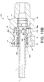
Figs. 10A-10F illustrate another embodiment of afitting assembly 200 that provides for a single action push to connect operation as in other embodiments hereinabove. This embodiment may be but need not be similar to the embodiments ofFigs. 1-9 hereinabove except as otherwise noted. Therefore, the overall description does not need to be repeated and like reference numerals are used for like parts.Fig. 10A corresponds withFig. 2 , and shows thefitting assembly 200 with the conduit C fully inserted and retained;Fig. 10B corresponds withFig. 7 , and shows the conduit C partially inserted;Fig. 10C corresponds withFig. 10A with the fitting assembly under pressure from a working fluid (not shown) contained by thefitting assembly 200; andFig. 10D corresponds withFig. 3 .Figs. 10E and 10F are enlarged perspective views of a retainer embodiment. - The principal difference between the embodiments of
Figs. 10A-10F and embodiments ofFigs. 1-9 is the design of theretainer 202, as contrasted with theretainer 52 inFigs. 1-7 and theretainer 92 inFigs. 8 and9 . Theretainer 202, in addition to functioning as a carrier for the gripping portion (e.g., conduit gripping members or bearing members 56), also provides a second conduit engaging feature or portion (e.g., a conduit colleting feature or colleting portion) by which theretainer 202 collets or otherwise engages the conduit C outboard of theconduit gripping members 56. In one such embodiment, the colleting portion when radially compressed acts as a collet and the colleting action is effected at a location that is axially between the source of the vibration and/or flexure of the conduit and the contact stress points between theconduit gripping devices 56 and the conduit C outer surface. This colleting action thereby provides further support of the conduit C and helps isolate or reduce the effects of the conduit vibration and flexure from the stress points in the conduit caused by theconduit gripping members 56, particularly when thefitting assembly 200 is under pressure. The colleting feature is utilized in additional embodiments in this disclosure. - The retainer 202 (see also
Figs. 10E and 10F ) for thefitting assembly 200 in an embodiment may include an annular retainer body 204 (also herein we refer to the retainer body as a ball carrier or ball cage) having at a first, proximal oroutboard end portion 206 that includes a radially outwardly projectingflange 208. Theflange 208 may be an annular continuous portion that presents aninboard facing wall 208a that cooperates with the inwardly projectingrib 70 of the secondfitting component 14, in this example the male threadednut 20, to retain the biasingmember 58 in compression. Two ormore wall portions 210 extend axially from theflange 208 to adistal end portion 212. Thedistal end portion 212 may include one ormore ball cavities 64 which retain and position theconduit gripping members 56, capturing the conduit gripping members between theretainer body 204 and thetapered surface 66a of thenut 14. Theconduit gripping members 56 may be realized in the form ofspherical balls 56, which provide for relatively small surface contact between the conduit gripping members and the outer surface of the conduit, for example, to facilitate gripping indentation of the conduit surface by the gripping members. - For an embodiment of the
retainer body 204 having twowall portions 210, thewall portions 210 preferably are diametrically opposed to each other, thereby presenting slots oropenings 214 between thewall portions 210 and extending axially towards thedistal end portion 212 of theretainer body 204. If more than twowall portions 210 are used, then preferably thewall portions 210 are evenly spaced circumferentially about theretainer body 214. A plurality of radially flexible members orfingers 216 extend in an axial direction (that may be generally parallel with the longitudinal axis X) and in a cantilevered manner from the facingwall 208a. In the illustrated embodiment, theflexible members 216 are integral with theretainer body 204. In other embodiments (not shown), the flexible members may be provided as one or more separate components assembled with the retainer body. - The
flexible members 216 extend within arespective slot 214 betweenadjacent wall portions 210, and there may be one or moreflexible members 216 in eachslot 214. In an embodiment, eachflexible member 216 at a distal end thereof projects radially outward to form an associatedtab 218. Eachtab 218 may present a radially outer land orend portion 220 that is positioned so as to contact thetapered wall 66a, at least when an outward axial load is applied to theretainer body 204, and a radiallyinner colleting surface 222 positioned to make direct contact with the outside surface of the conduit C as further described below. Because theretainer 202 is annular, eachflexible member 216 may have a curvature that coincides with the overall annular shape of theretainer body 204. Therefore, preferably but not necessarily, eachcolleting surface 222 is a curved surface that preferably but not necessarily coincides with the curvature of the conduit C, at least when theland 220 is radially pressed against the conduit C outer surface. This arrangement may provide for a larger colleting surface contact area (the combined areas of the conduit contacting surfaces of the flexible member end portions) as compared to the gripping surface contact area (the combined areas of the conduit contacting surfaces of the bearing members). - The biasing
member 58, theretainer 202, theballs 56 and the secondfitting component 14 in the form of the male threadednut 20, form a standalone subassembly similar to the embodiment ofFig. 5 . This subassembly threadably mates with the firstfitting component 12 in the form of the female threadedbody 18 to complete thefitting assembly 200. - With reference to
Fig. 10B , when the conduit C is withdrawn from thefitting assembly 200, or at least the conduit end is axially inserted up to but not past the position of theballs 56, the biasingmember 58 pushes theretainer body 204 axially outward (to the left as viewed inFig. 10B ) but is restrained with the secondfitting component 14 because theballs 56 become wedged between thetapered wall 66a and the associatedball cavity 64. As the conduit C is further inserted, theballs 56 move axially inward and radially outward along thetapered wall 66a, so that theretainer 202 is pushed forward or in an inboard direction. Theballs 56 move radially outward until the conduit can move past theballs 56 and be fully inserted in the firstfitting component 12 to the position shown inFig. 10A . This operation may be the same as the embodiment ofFigs. 1-7 above. - Once the tube is fully inserted, the biasing
member 58 biases theretainer 202 outboard so that the conduit C is fixed in place by wedging theballs 56 between thetapered wall 66a and the conduit C outer surface. When the fitting assembly (with inserted conduit) is not subjected to an additional or external outboard axial load (e.g., pressure from a working fluid contained by the fitting assembly, or a pulling force applied to the conduit), as inFig. 10A , a radial gap may, but need not, be present between the tab lands 220 and the conduit C outer surface. In other embodiments, the flexible members may be configured to contact an outer surface of the inserted conduit upon conduit insertion, with the biasing force of the biasingmember 58 being sufficient to effect colleting engagement of the flexible members with the conduit. - When the
fitting assembly 200 is under fluid pressure as illustrated inFig. 10C , the fluid pressure acts against theseal member 44 which axially applies a load or biasing force against theretainer body 204 in an outboard direction, to bias the gripping portion (balls 56) toward gripping engagement with the conduit, and to bias the colleting portion (flexible members 216) toward colleting engagement with the conduit. This added load cause theballs 56 to indent (or further indent) into the conduit C outer surface by an amount that depends on the amount of fluid pressure. This indentation is illustrated in a somewhat exaggerated manner for clarity and labeled Y inFig. 10C . The greater the fluid pressure, the greater will be theball 56 indentation. This indentation also produces a small axial shift or movement of theretainer body 204 relative to thetapered wall 66a, which results in thetabs 218 of theflexible members 216 becoming wedged between thetapered wall 66a and the outer surface of the conduit C. This wedging action of thetabs 218 produces a radial compression or flexing of the tab lands 220 against the conduit C outer surface which causes a colleting action axially outboard of theballs 56. The colleting action increases radial load on the conduit to enhance conduit support, adds rigidity to thefitting assembly 200 and reduces or helps isolate stress experienced in the area of contact between theballs 56 and the conduit C. Such stress may arise, for example, from conduit vibration and conduit rotary flexure from elsewhere in the fluid system to which the conduit C is connected. Thetabs 218 also resist further axial movement of theretainer 202 under pressure so as to increase conduit grip and restrict further compression of theballs 56 into the conduit C surface. - The
retainer body 204 preferably but not necessarily is formed as an integral one-piece component, preferably made of metal such as stainless steel to name one example of many. In other embodiments, the gripping portion may likewise be formed from one or more axially extending, radially flexible members, similar to the flexible members of the embodiment ofFigs. 10A-10F , with conduit gripping tabs or end portions shaped to provide gripping (e.g., indenting) engagement of the conduit (e.g., by providing a sharper or smaller conduit engaging surface).Fig. 10D illustrates thefitting assembly 200 in exploded perspective. - In the embodiment of
Figs. 10A-10F , like the embodiments ofFigs. 1-9 , theseal device 40 provides a fluid tight seal between the first fitting component (e.g., fitting body) 12 and the inserted conduit C. In other embodiments, a seal device may provide a fluid tight seal between the second fitting component (e.g., fitting nut) and the inserted conduit. - With reference then to
Figs. 11A-11I , we provide other embodiments of afitting assembly 250 that uses aretainer 270 to provide gripping and colleting actions. - In an embodiment, a
fitting assembly 250 includes a firstfitting component 252, for example, a female threadedfitting port 252. For example, theport 252 may be a female threadedbody 254 that receives the conduit C end and may be a standard SAE configuration. - The first
fitting component 252 threadably mates with a secondfitting component 256, such as a male threadednut 258. The male threadednut 258 includes atool engaging flange 260 at a distal outboard end thereof. Aseal groove 262, for retaining anouter seal 264 that may be, for example, an o-ring, is provided between theflange 260 and thethreads 266 of the male threadednut 258. When the male threadednut 258 is connected with the female threadedport 252, theouter seal 264 is sealingly compressed between theseal groove 262 and a facingsurface 268 of the female threadedbody 254. Theouter seal 264 therefore provides a body seal for the fitting assembly 250 (e.g., to compensate for the lack of a direct seal between the fitting body and the inserted conduit). - The
fitting assembly 250 further includes aretainer 270 which may be an assembly of an annular retainer body orball carrier 272, one or moreconduit gripping members 274, a biasingmember 276, agland 278 and anoptional retaining member 280. Theconduit gripping members 274 may be realized in the form of spherical balls and the biasingmember 276 may be a spring. Theball carrier 272 may be used to position and retain theballs 274 axially aligned with atapered surface 282 formed in the male threadednut 258. Theball carrier 272 may include one ormore ball cavities 284 that position theballs 274 between thetapered surface 282 and the outer surface of the conduit C. Theball carrier 272 includes at a first end aflange 286 that faces inboard to engage with the biasingmember 276. The biasingmember 276 is positioned in compression between theflange 284 and anoutboard facing surface 288 of thegland 278. Thegland 278 further includes an outerperipheral groove 290 that receives the retainingmember 280, which may be in the form of a snap ring. Thegland 278 presents an inboard facingend surface 292 that engages aseal backing ring 294 which is disposed between thegland 278 and aninner seal 296, which may be realized in the form of an o-ring for example. Asecond gland 298 is provided to help retain theinner seal 296 in position within the male threadednut 258. - The retaining
member 280 is partially received in and axially aligned with aretainer groove 300 that is provided in the male threadednut 258. After assembly, the retainingmember 280 snaps outward and will interfere with ashoulder 302 of theretainer groove 300. With theball carrier 272 axially aligned with thetapered surface 282, theball carrier 272, the biasingmember 276, and thegland 278 are retained with the male threadednut 258 by the retainingmember 280 as a subassembly, even when the nut is disassembled from the fitting body. We refer to this configuration as an embodiment of an inverted colleting ball lock concept because the biasingmember 276 applies an axial force against theball carrier 272 to engage theballs 274 with thetapered surface 282 without placing an axial load on theinner seal 296 and minimizing radial interference between the conduit C and theinner seal 296 which could otherwise cause damage to the seal. - The
first gland 278 is preferably but not necessarily an annular continuous component, as may be thesecond gland 298. - With reference to
Figs. 11B and 11C , in two embodiments of theball carrier 272, 272', theball carrier 272, 272' may be used to position theballs 274, 274' but also to provide a colleting function as previously described in the embodiment ofFigs. 10A-10F . In one embodiment (Fig. 11B ), theball carrier 272 may include acarrier body 304 having a plurality of preferably circumferentially evenly spacedflexible members 306 that extend axially from theflange 286 and withaxial slots 308 therebetween. Theseflexible members 306 preferably extend in a cantilevered fashion from theflange 286 so as to have radial flexibility. At the distal end of eachflexible member 306 is atab 310 having a radially outer tab land orend portion 311, and a radiallyinner colleting surface 312 positioned to make direct contact with the outside surface of the conduit C as further described below. Because theretainer body 272 is annular, eachflexible member 306 may have a curvature that coincides with the overall annular shape of theretainer body 272. Therefore, preferably but not necessarily, eachcolleting surface 312 is a curved surface that preferably but not necessarily coincides with the curvature of the conduit C, at least when theland 311 is radially pressed against the conduit C outer surface. - The distinction between the two embodiments of
Figs. 11B and 11C is that in the embodiment ofFig. 11C , adjacent slots 308' extend in opposite directions. This allows greater arcuate land surface area for each tab colleting surface 312' if so needed, for example, to further increase the colleting surface contact area. Also, by having slots extending from the flange 286', the flange 286' has increased flexibility so that the inboard flanged end 286' may also be configured to collet the conduit. In one such embodiment, the flange may be sized to engage the taperedsurface 282 for radially inward flexing of the flange end in response to axial outboard movement of the retainer body, to provide a second colleting portion inboard of the gripping portion. Moreover, in an embodiment as illustrated inFig. 11C , the entire length of the carrier body 304' can collet the conduit C. Also, about the entire circumference of the carrier body 304' there is a portion of the carrier body 304' in colleting contact with the conduit C. - As in the embodiment of
Figs. 10A-10F , the tab colleting surfaces 312, 312' provide the conduit colleting function at a position that is axially between the source of vibration and flexure into the conduit and the stress locations for theballs 274 gripping and indenting into the conduit C. It will be noted that thetabs 310 become wedged between thetapered surface 282 and the outer surface of the conduit C and radially compressed against the conduit outer surface. This colleting function provides conduit support, isolation or reduction of the conduit vibration and flexure, and reduces or limits additional indentation of theballs 274 into the conduit C. - In comparing
Fig. 11A withFigs. 11D-11E ,Fig. 11A shows thefitting assembly 250 without pressure andFigs. 11D and 11E show thefitting assembly 250 under pressure. When under pressure, theinner seal 296 applies an axial load against thegland 278 which places an axial load on theball carrier 272. In the unpressurized condition, there may be a small radial gap between the tab lands 311 and thetapered surface 282, and/or a small radial gap between the tab colleting surfaces 312 and the conduit C. Under pressure, theballs 274 indent into the conduit surface allows theretainer 270 to shift axially slightly so that thetabs 310 contact thetapered surface 282 and begin to collet against the conduit outer surface. The colleting action restrains further axial movement of theball carrier 272, supports the conduit, adds rigidity to thefitting assembly 250 and isolates or reduces the effects of vibration and flexure of the conduit on the stress regions of theballs 274 against the conduit C. -
Fig. 11F illustrates position of the fitting assembly members as the conduit is being inserted. As in the prior embodiments, as the conduit is inserted, theballs 274 can radially expand to allow the conduit to pass through. As soon as the conduit passes axially past theballs 274, the conduit is trapped against being axially withdrawn. -
Fig. 11G illustrates an embodiment of aconduit removal tool 314 with thefitting assembly 250. Thetool 314 may include anenlarged flange 316 that can be manually grasped or otherwise axially moved. Thetool 314 further includes a thintubular extension 315 of sufficient length that thedistal end 318 of the tool may be axially pushed against theoutboard end 320 of theball carrier body 304. In this manner, theball carrier body 304 may be axially pushed inward against the force of the biasingmember 276, which allows theballs 274 to expand radially outward to permit the conduit C to be withdrawn from thefitting assembly 250. -
Fig. 11H illustrates an alternative embodiment in which aretaining ring 322 may be used to retain theseal backing ring 294,inner seal 296, andsecond gland 298 with the male threadednut 258. In this manner, the secondfitting component 256 may be realized as a self-contained cartridge or subassembly that can be mated up with many differentfemale ports 252. -
Fig. 11I is an exploded perspective illustration of thefitting assembly 250 including the retainingring 322 embodiment. - With reference next to
Figs. 12A and12B , we provide another embodiment of a single action push to connectfitting assembly 350 that includes a colleting feature. In addition, thefitting assembly 350 comprises all parts that are non-polymeric. For example, all the parts may be metal, such as for example 316 stainless steel, or may include non-polymeric composite materials such as ceramics and so on. By eliminating polymer based sealing components, thefitting assembly 350 may be used in applications having operating temperatures higher or lower than temperatures that can be accommodated with polymeric components such as the seals. - In an embodiment, the
fitting assembly 350 may be but need not be similar or the same as the embodiment ofFigs. 11A-11I above. In the illustrated embodiment ofFigs. 12A and12B , however, we omit the retainingmember 280. The fitting assembly may include theretainer 270 having theball carrier 272, the conduit gripping devices orballs 274, the biasingmember 276 and thegland 278. Since we do not use the retainingmember 280 in this embodiment, thegland 278 does not need to have theouter groove 290. Therefore, theretainer 270 is not held together as a subassembly with the secondfitting component 352, which may be a male threaded nut. - In place of the
inner seal 296, theseal backing ring 294 and thesecond gland 298, we use anon-polymeric sealing member 354 and aseal supporting gland 356, such that the seal device forms a non-polymeric seal between the conduit and the second fitting component or nut. In other embodiments (not shown), a non-polymeric sealing member may be provided to form a non-polymeric seal between the conduit and the first fitting component or body. - The
non-polymeric seal 354 may be realized in many different forms, including but not limited to a commercially available all-metal lip seal. Thelip seal 354 is commonly available in a C-shaped cross-section having a distal end that forms a facingwall 358. Lip seals typically are used in an orientation in which the open side or end 360 faces the high pressure side of thefitting assembly 350 as illustrated inFig. 12B . Alternatively, other non-polymeric seals may be used, for example, an all metal C-seal well known to those skilled in the art and which is a traditional radially loaded seal to seal shafts. Lip seals and C-seals and axial seals are commercially available from a number of sources, including JetSeal Inc. of Spokane, WA, or Nicholson Sealing Technologies, Ltd., of Stanley, UK - Preferably, the supporting
gland 356 has an extended axial length so that when thefitting assembly 350 is fully assembled, theback end 362 of the supportinggland 356 contacts asurface 364 of the firstfitting component 366, which may be a female threaded body or port. The supportinggland 356 extends axially towards theretainer 270, and may include a reduceddiameter neck portion 368 so that theneck portion 368 may be received in the openinterior portion 370 of thelip seal 354. The axial length of the supportinggland 356 is preferably selected so that when thefitting assembly 350 is fully assembled, an inboard end of theneck portion 368 contacts and supports the facingwall 358 under axial load of the biasingmember 276 so that the radial seal load on thelip seal 354 is maintained. Insertion of the conduit C into thefitting assembly 350, as well as retention and release of the conduit C with respect to thefitting assembly 350, may be similar to the embodiment ofFigs. 11A-11I above. - With reference to
Figs. 13A-13C , we illustrate another embodiment of a single action push to connectfitting assembly 380 that provides a colleting feature. Note thatFig. 13C is an enlarged illustration of the fitting assembly in half cross-section. Thefitting assembly 380 shares many common elements as the embodiments ofFigs. 10A through 12A , but in a male configuration. By male configuration is meant that the fitting component that receives the conduit is a male threaded body and the mating fitting component is a female threaded nut. This is in comparison to the earlier embodiments which are a female configuration, for example, the female threaded ports, wherein the conduit receiving fitting component is a female threaded body and the mating component is a male threaded nut. - The
fitting assembly 380 may include a firstfitting component 382 in the form of a male threadedbody 384 and a mating secondfitting component 386 in the form of a female threadednut 388. Although in all the exemplary embodiments herein we show threaded mechanical connections between the first fitting component and the second fitting component, non-threaded connections may alternatively be used, for example, crimped connections. - The male threaded
body 384 includes aconduit end socket 390 and may optionally present acounterbore shoulder 392 against which the conduit is bottomed in the final assembled condition. The male threadedbody 384 further includes a throughbore 394 in which is disposed aninner seal member 396 that provides a fluid tight seal against the conduit C when the fitting connection is complete, as shown inFig. 13A . Agland 398 is also received in the male threadedbody 384 with abacking ring 400 disposed between theoutboard end 402 of the gland and theinner seal member 396. Preferably, thegland 398 includes an optional outwardly flaredend 404 that contacts anend portion 406 of the male threadedbody 384 so that the axial movement of thegland 398 towards theinner seal member 396 is limited. This not only prevents thegland 398 from axially compressing theinner seal member 396, but also provides a stop position so that a biasingmember 408 is compressed between aninboard end 410 of thegland 398 and aball carrier 412. - A
retainer 414 is provided that may be but need not be the same as theretainer 270 of the embodiment ofFigs. 11A-11I . Theretainer 414 may include theball carrier 412, one or moreconduit gripping members 416, for example, in the form ofspherical balls 416, the biasingmember 408 and thegland 398. Theball carrier 412 may be the same as theball carrier 272 so that description is not repeated. Theball carrier 412, under the axial force provided by the biasingmember 408, engages with atapered surface 418 presented in the female threadednut 388. Theball carrier 412 axially aligns and positions theballs 416 relative to the taperedsurface 418 so that after the conduit is inserted past theballs 416, theballs 416 are trapped between thetapered surface 418 and the outer surface of the conduit C, as depicted inFig. 13A . Therefore, the conduit C cannot be withdrawn from thefitting assembly 380. As in the previous embodiments described above, theball carrier 412 includes a plurality of flexiblemembers having tabs 420 that function to collet the conduit when the fitting is pressurized. When pressurized, the fluid pressure applies an axial force on theinner seal member 396 which transmits the axial force through thegland 398 and the biasingmember 408 to theball carrier 412. Theballs 416 indent into the outer surface of the conduit C which allows thetabs 420 to be compressed between thetapered surface 418 and the conduit, thereby colleting the conduit. Note fromFig. 13C which shows thefitting assembly 380 in an unpressurized condition, that there preferably is aradial gap 424 between thetabs 420 and thetapered surface 418. This gap is also present in other of the embodiments herein in the unpressurized state as described hereinabove. - It should be noted that a lip seal, C-seal or other non-polymeric seal may be used in place of the
inner seal member 396 and thebacking ring 400 in manner that may be similar to the embodiment ofFigs. 12A and12B . Also, as in the embodiment ofFig. 11G , atool 314 may be used to release the conduit C from the assembledfitting assembly 380. Note that thetool 314 may be used with various of the disclosed embodiments herein. - Also, it should be noted that although the exemplary embodiments herein preferably use conduit that has a smooth hollow cylindrical geometry, the conduit may alternatively have a groove or recess formed in the outer surface of the conduit wall at an axial position that aligns with the conduit gripping members such as the spherical balls. The groove or recess can in some applications enhance the conduit grip by the conduit gripping members because the balls will not have to be forced to indent into the conduit surface. Engagement of the conduit gripping members with the conduit groove may also provide a detectable positive indication of full insertion or installation of the conduit in the fitting assembly. The colleting action of the colleting portion against the outer surface of the conduit, outboard of the groove, reduces stress concentrations at the conduit groove, which may otherwise result from vibration or flexure of the conduit outboard of the groove. Exemplary conduit grooves C2 are illustrated in phantom in
Figs. 10C ,11E ,12B , and13C . -
Fig. 14 illustrates another embodiment of aball carrier 430. Rather than manufacturing a single piece component for theball carrier 430, theball carrier 430 may be made using a plurality of interconnected arcuate sections orsegments 432. Eachsection 432 includes amale pin 434 and afemale slot 436 that can be connected so thatadjacent sections 432 are securely held together. Eachsection 432 may includeflexible members 438 withtabs 440 at the distal end portions. Note that eachsection 432 preferably has a curvature that is compliant with the size of the conduit and the fitting assembly. Eachsection 432 may also include aball cavity 442 that receives a conduit gripping member such as aspherical ball 444. - The inventive aspects and concepts have been described with reference to the exemplary embodiments. Modification and alterations will occur to others upon a reading and understanding of this specification. It is intended to include all such modifications and alterations insofar as they come within the scope of the appended claims.
Claims (13)
- A push to connect fitting assembly for a conduit having a longitudinal axis, the fitting assembly comprising:a first fitting component (12, 252, 366, 382) having an outboard end that is adapted to receive a conduit end;a second fitting component (14, 256, 352, 386) joined to the first fitting component to define an interior cavity;a seal device (40) disposed in the interior cavity, wherein the seal device seals one of the first and second fitting components with an outer surface of a conduit end (C) when the conduit end is inserted into the outboard end of the first fitting component; anda retainer (202, 270, 414) assembled with at least one of the first and second fitting components, the retainer including an annular retainer body (204, 272, 412), and a gripping portion comprising a plurality of circumferentially spaced bearing members (56, 274, 416) captured between the retainer body and the at least one of the first and second fitting components to engage the inserted conduit end over a first surface contact area to grip the conduit end,the retainer further including a colleting portion outboard of the gripping portion, the colleting portion comprising a plurality of axially extending, radially flexible fingers (216), each flexible finger (216) at a distal end thereof projects radially outward to form an associated tab (218), the fingers (216) having conduit contacting surfaces (222) that engage the inserted conduit end over a second surface contact area greater than the first surface contact area to collet the inserted conduit end.
- The fitting assembly of claim 1, wherein the retainer further includes a second colleting portion (286') inboard of the gripping portion.
- The fitting assembly of any of claims 1 and 2, wherein each of the plurality of axially extending, radially flexible fingers is integral with the retainer body.
- The fitting assembly of any of claims 1-3, further comprising a biasing member (58, 276, 408) disposed between the second fitting component and the retainer to axially bias the retainer.
- The fitting assembly of claim 4, wherein the second fitting component comprises a tapered interior surface that engages at least one of the bearing members and the flexible fingers to move the at least one of the bearing members and the flexible fingers radially inward toward engagement with the outer surface of the inserted conduit end.
- The fitting assembly of any of claims 4 and 5 wherein the biasing member axially biases both the bearing members and the flexible fingers into engagement with the tapered interior surface.
- The fitting assembly of any of claims 1-6, wherein the seal device forms an all metal seal between one of the first and second fitting components and the outer surface of the inserted conduit end.
- The fitting assembly of any of claims 1-7, wherein the seal device includes an annular lip seal having an inboard facing C-shaped cross section.
- The fitting assembly of claim 8, wherein the seal device further includes a supporting gland having a first end adjacent an inner shoulder portion of the first fitting component, and a second end received in the C-shaped cross-section of the annular lip seal.
- The fitting assembly of any of claims 1-9, wherein the conduit contacting surfaces of the flexible fingers define a curved inner surface conforming to a cylindrical outer surface of the inserted conduit end.
- The fitting assembly of any of claims 1-10, wherein the second fitting component and the retainer are retained together as a subassembly when the second fitting component is disassembled from the first fitting component.
- The fitting assembly of any of claims 1-11, wherein the conduit contacting surfaces of the flexible fingers are separated from the outer surface of the inserted conduit end by a radial gap when no external outward axial load is applied to the inserted conduit end.
- The fitting assembly of any of claims 1-12, wherein when the conduit end is inserted into the outboard end of the first fitting component and a fluid pressure is applied to the fitting assembly, the seal device is pressurized to apply a biasing force to the bearing members to bias the bearing members toward gripping engagement with the inserted conduit end and to the flexible fingers to bias the flexible fingers toward colleting engagement with the inserted conduit end.
Priority Applications (1)
| Application Number | Priority Date | Filing Date | Title |
|---|---|---|---|
| EP19194993.2A EP3597979B1 (en) | 2015-04-23 | 2016-04-22 | Single action push to connect conduit fitting with colleting |
Applications Claiming Priority (2)
| Application Number | Priority Date | Filing Date | Title |
|---|---|---|---|
| US201562151465P | 2015-04-23 | 2015-04-23 | |
| PCT/US2016/028741 WO2016172408A1 (en) | 2015-04-23 | 2016-04-22 | Single action push to connect conduit fitting with colleting |
Related Child Applications (1)
| Application Number | Title | Priority Date | Filing Date |
|---|---|---|---|
| EP19194993.2A Division EP3597979B1 (en) | 2015-04-23 | 2016-04-22 | Single action push to connect conduit fitting with colleting |
Publications (2)
| Publication Number | Publication Date |
|---|---|
| EP3286476A1 EP3286476A1 (en) | 2018-02-28 |
| EP3286476B1 true EP3286476B1 (en) | 2019-10-02 |
Family
ID=55861274
Family Applications (2)
| Application Number | Title | Priority Date | Filing Date |
|---|---|---|---|
| EP16719710.2A Active EP3286476B1 (en) | 2015-04-23 | 2016-04-22 | Push to connect fitting assembly for a conduit |
| EP19194993.2A Active EP3597979B1 (en) | 2015-04-23 | 2016-04-22 | Single action push to connect conduit fitting with colleting |
Family Applications After (1)
| Application Number | Title | Priority Date | Filing Date |
|---|---|---|---|
| EP19194993.2A Active EP3597979B1 (en) | 2015-04-23 | 2016-04-22 | Single action push to connect conduit fitting with colleting |
Country Status (9)
| Country | Link |
|---|---|
| US (2) | US10704722B2 (en) |
| EP (2) | EP3286476B1 (en) |
| JP (2) | JP6845155B2 (en) |
| KR (1) | KR102534555B1 (en) |
| CN (1) | CN107532758B (en) |
| CA (1) | CA2983777A1 (en) |
| ES (1) | ES2755400T3 (en) |
| IL (1) | IL254950A0 (en) |
| WO (1) | WO2016172408A1 (en) |
Families Citing this family (8)
| Publication number | Priority date | Publication date | Assignee | Title |
|---|---|---|---|---|
| CA3113774C (en) * | 2017-10-06 | 2022-03-08 | Quick Fitting Holding Company, Llc | Cable securing device |
| CN108533855A (en) * | 2018-03-02 | 2018-09-14 | 广东思豪流体技术有限公司 | A kind of connector |
| US11802643B2 (en) | 2018-04-24 | 2023-10-31 | Reliance Worldwide Corporation | Fluid connector |
| CN115355381A (en) | 2018-08-14 | 2022-11-18 | 诚信全球公司 | Tubular connector |
| US11707809B2 (en) * | 2019-05-15 | 2023-07-25 | Waters Technologies Corporation | Method and apparatus for high pressure sealing |
| WO2021183911A1 (en) | 2020-03-13 | 2021-09-16 | Reliance Worldwide Corporation | Push-to-connect fitting providing an insertion indication |
| US11826270B2 (en) | 2020-10-29 | 2023-11-28 | Clearstream Technologies Limited | Connector for transfer of an implant to a catheter |
| CN114962826B (en) * | 2022-06-16 | 2024-03-08 | 中海石油(中国)有限公司 | Underwater hydraulic loading telescopic connector |
Family Cites Families (207)
| Publication number | Priority date | Publication date | Assignee | Title |
|---|---|---|---|---|
| DE1987355U (en) | 1968-06-12 | Erich Wegner, 1000 Berlin | Hitch for cladding panels and the like on concrete surfaces | |
| US1337288A (en) | 1918-05-07 | 1920-04-20 | Strause Gas Iron Co | Gas-fixture and fuel-hose therefor |
| US2062628A (en) | 1935-01-25 | 1936-12-01 | Yannetta Peter | Clutch lock |
| US2310744A (en) * | 1941-04-23 | 1943-02-09 | Alden E Osborn | Pipe joint |
| US2429202A (en) | 1943-02-05 | 1947-10-21 | B R Engineering Company | Fluid coupling |
| US2561887A (en) | 1948-11-16 | 1951-07-24 | Dresser Ind | Ball lock coupling |
| US2702202A (en) | 1950-06-23 | 1955-02-15 | Aeroquip Corp | Packed-socket pipe coupling with releasable pipe retaining means |
| US2914344A (en) | 1955-04-06 | 1959-11-24 | Union Carbide Corp | Quick detachable safety connection between blowpipe body and stem |
| US2848256A (en) * | 1955-11-21 | 1958-08-19 | Good All Electric Mfg Co | Pipe connector |
| US2848135A (en) | 1957-07-03 | 1958-08-19 | Mcdowell Mfg Co | Coupling nose fitting |
| AT228575B (en) | 1960-11-09 | 1963-07-25 | Rollmaplast Ag | Detachable socket connection |
| US3398977A (en) | 1965-02-13 | 1968-08-27 | Yoneda Rikizo | Pipe coupling |
| US3453005A (en) | 1968-04-08 | 1969-07-01 | Scovill Manufacturing Co | Quick-connect safety coupling |
| US3773360A (en) | 1972-09-01 | 1973-11-20 | W Timbers | Quick disconnect coupling |
| US3887222A (en) | 1974-07-25 | 1975-06-03 | Hansen Mfg | Coupling with push-pull release |
| US4055359A (en) | 1975-11-17 | 1977-10-25 | Ford Motor Company | Quick-connect tubular couplings |
| AU509587B2 (en) | 1976-01-19 | 1980-05-15 | Sekisui Kagaku Kogyo Kabushiki Kaisha | Pipe joint endless locking ring and groove arrangement |
| US4105226A (en) | 1976-06-01 | 1978-08-08 | Celanese Corporation | Snap-in fittings and coupling ring therefor |
| US4163573A (en) | 1977-02-28 | 1979-08-07 | Chiyoda Tsusho K.K. | Hose fitting |
| US4191408A (en) | 1977-05-27 | 1980-03-04 | The Weatherhead Company | Automotive quick connect tube coupling |
| DE2741512A1 (en) | 1977-09-15 | 1979-04-05 | Kurt Schildmann | Quick-action compressed air pipe coupling - has secondary row of locking balls engaged by protrusion on sliding sleeve |
| US4135745A (en) | 1977-12-23 | 1979-01-23 | Ford Motor Company | Quick connect fluid fitting |
| JPS5730545Y2 (en) | 1978-04-29 | 1982-07-05 | ||
| US4193616A (en) | 1978-05-18 | 1980-03-18 | Dana Corporation | Quick connect fitting |
| DE2824943C2 (en) | 1978-06-07 | 1986-07-31 | Armaturenfabrik Hermann Voss GmbH + Co, 5272 Wipperfürth | Connection device for brake lines |
| DE7914106U1 (en) | 1979-05-16 | 1979-08-23 | Gustav Eisele, Metallwarenfabrik, 7050 Waiblingen | DEVICE FOR FASTENING A CONNECTING NIPPLE TO A HOSE |
| DE2922869A1 (en) | 1979-06-06 | 1980-12-18 | Voss Armaturen | Pressure fluid plug connector - with added lip seal and O=rings for better tightness |
| FR2461876A1 (en) | 1979-07-23 | 1981-02-06 | Staubli Sa Ets | IMPROVEMENTS TO QUICK CONNECTION DEVICES FOR JOINING PIPES |
| US4240654A (en) | 1979-09-28 | 1980-12-23 | International Harvester Company | Hose end coupling unit |
| US4304422A (en) | 1980-02-19 | 1981-12-08 | Gould Inc. | Tube coupling with frangible sleeve |
| FR2479406B1 (en) | 1980-03-28 | 1985-08-23 | Legris | INSTANT FITTINGS FOR BARE AND SMOOTH TUBES |
| JPS56151585U (en) * | 1980-04-11 | 1981-11-13 | ||
| JPS5920462B2 (en) | 1980-04-26 | 1984-05-14 | 株式会社サト− | Printing device ribbon break detection mechanism |
| GB2104607A (en) | 1981-08-21 | 1983-03-09 | Wilkinson Sword Ltd | Hose couplings |
| US4401326A (en) | 1981-12-16 | 1983-08-30 | Ford Motor Company | Quick-connect tubular coupling |
| US4752088A (en) | 1982-03-29 | 1988-06-21 | Carboloy Inc. | Tool adapter assembly and extended compression/tension tap driver |
| US4455177A (en) | 1982-09-13 | 1984-06-19 | Filippov Vladimir I | Method and apparatus for chemical heat treatment of steel parts utilizing a continuous electric furnace |
| FR2545908B1 (en) | 1983-05-10 | 1985-07-12 | Staubli Sa Ets | QUICK SAFETY CONNECTOR FOR REMOVABLE JOINING OF PIPES |
| US4540201A (en) | 1983-05-16 | 1985-09-10 | Tuthill Corporation | Tube connector |
| GB8406580D0 (en) | 1984-03-13 | 1984-04-18 | Walmsley O | Pipe connector |
| DE3569604D1 (en) | 1984-03-13 | 1989-05-24 | Owen Walmsley | Clamps |
| FR2577300B1 (en) | 1985-02-08 | 1987-08-21 | Fremy Raoul | QUICK CONNECTION WITH RADIAL MOVEMENT LOCK |
| US4685706A (en) | 1985-03-04 | 1987-08-11 | Clevite Industries Inc. | Releasable push-to-connect tube fitting |
| US4645245A (en) | 1985-10-07 | 1987-02-24 | General Motors Corporation | Quick connect tube coupling |
| US4893810A (en) | 1986-07-21 | 1990-01-16 | Lee Scott H | Quick release collar |
| US4719971A (en) | 1986-08-18 | 1988-01-19 | Vetco Gray Inc. | Metal-to-metal/elastomeric pack-off assembly for subsea wellhead systems |
| US4802696A (en) * | 1986-10-23 | 1989-02-07 | The Gates Rubber Company | Quick connect coupling |
| US4813716A (en) | 1987-04-21 | 1989-03-21 | Titeflex Corporation | Quick connect end fitting |
| US4750765A (en) | 1987-07-27 | 1988-06-14 | Stratoflex, Inc. | Quick-connect coupling |
| US4793637A (en) | 1987-09-14 | 1988-12-27 | Aeroquip Corporation | Tube connector with indicator and release |
| US5042848A (en) | 1987-11-16 | 1991-08-27 | Fujipura Seiko Co. | Swivelable connector for tubular conduits |
| US4779107A (en) | 1987-12-21 | 1988-10-18 | Weisfield Richard L | Modulation electrodes having improved corrosion resistance |
| US4834423A (en) | 1987-12-22 | 1989-05-30 | Schmelzer Corporation | Quick connect fluid fitting assembly |
| US4906031A (en) | 1988-07-21 | 1990-03-06 | Stratoflex, Inc. | Quick connect coupling with garter spring |
| US4872710A (en) | 1988-10-07 | 1989-10-10 | Stratoflex, Inc. | Releasable quick connect fitting |
| US4900066A (en) | 1988-11-01 | 1990-02-13 | Vetco Gray Inc. | Pipe connector |
| US4923228A (en) | 1988-12-12 | 1990-05-08 | Aeroquip Corporation | Integral quick-connect tube connector |
| US5005877A (en) | 1988-12-16 | 1991-04-09 | Parker Hannifin Corporation | Quick connect/disconnect fluid coupling |
| CA2004975A1 (en) | 1988-12-16 | 1990-06-16 | Lawrence F. Hayman | Quick connect/disconnect fluid coupling |
| US5041997A (en) | 1989-02-06 | 1991-08-20 | Hewlett-Packard Company | Lightwave component analyzer |
| US5022687A (en) | 1989-09-18 | 1991-06-11 | Yokohama Aeroquip Corporation | Pipe coupling |
| US5176409A (en) | 1989-11-11 | 1993-01-05 | Dixie Iron Works | High pressure pipe coupling |
| US5024468A (en) | 1989-11-13 | 1991-06-18 | Parker Hannifin Corporation | Push-in tube fitting and release tool |
| US5076541A (en) | 1989-12-15 | 1991-12-31 | A. Y. Mcdonald Manufacturing Company | Tamperproof rotary valve |
| US5044672A (en) | 1990-03-22 | 1991-09-03 | Fmc Corporation | Metal-to-metal sealing pipe swivel joint |
| JPH0439492A (en) * | 1990-05-31 | 1992-02-10 | Tokai Rubber Ind Ltd | Quick connector |
| US5284369A (en) | 1990-08-24 | 1994-02-08 | Tokai Rubber Industries, Ltd. | Quick connector |
| US5044401A (en) | 1990-11-20 | 1991-09-03 | Parker Hannifin Corporation | Integral valve and seal for a quick connect coupling |
| AU7438891A (en) | 1991-04-29 | 1992-10-15 | Kabushiki Kaisha Harmo Sogo Kenkyujo | Tubing joint |
| JP2941499B2 (en) | 1991-06-28 | 1999-08-25 | ミサワホーム株式会社 | Packing frame for roof unit |
| US5118140A (en) * | 1991-08-09 | 1992-06-02 | Ramer Products, Inc. | Tool for smooth wall tubes |
| US5246236A (en) | 1992-01-21 | 1993-09-21 | Halliburton Company | Seal for long-time exposures in oil and gas well tools |
| US5301408A (en) | 1992-03-31 | 1994-04-12 | R & B, Inc. | Garter spring coupling release tool |
| US5401065A (en) | 1992-05-11 | 1995-03-28 | Kabushiki Kaisha Toshiba | Fluid coupling |
| JP2624924B2 (en) | 1992-05-11 | 1997-06-25 | 株式会社東芝 | Fluid coupling |
| US5226682A (en) | 1992-07-21 | 1993-07-13 | Aeroquip Corporation | Coupling assembly |
| US5292156A (en) * | 1992-09-11 | 1994-03-08 | Nitto Kohki Co., Ltd. | Corrugated pipe coupling |
| DE4243844B4 (en) | 1992-12-23 | 2004-03-25 | Voss Automotive Gmbh | Connection device for pipes |
| WO1994015131A1 (en) | 1992-12-24 | 1994-07-07 | F.W. Talbot And Company Limited | Connectors |
| EP0615089A1 (en) | 1993-03-06 | 1994-09-14 | DEUTSCHE TECALEMIT GmbH | Separable plug-in connection for high pressure conduits |
| US5653480A (en) * | 1993-03-19 | 1997-08-05 | Bridgestone Flowtech Corporation | Pipe coupling |
| JPH06272795A (en) * | 1993-03-19 | 1994-09-27 | Bridgestone Flowtech Corp | Tube joint |
| JP3562876B2 (en) * | 1995-06-28 | 2004-09-08 | ブリヂストンフローテック株式会社 | Pipe fittings |
| JPH0830548B2 (en) * | 1993-06-08 | 1996-03-27 | 榊原 明 | Pipe connecting device |
| JPH07190272A (en) | 1993-12-28 | 1995-07-28 | Showa Alum Corp | Pipe connection device |
| US5470257A (en) | 1994-09-12 | 1995-11-28 | John Mezzalingua Assoc. Inc. | Radial compression type coaxial cable end connector |
| US5474336A (en) | 1994-09-20 | 1995-12-12 | Dana Corporation | Quick connect tube couplings |
| FR2727492B1 (en) | 1994-11-30 | 1996-12-27 | Legris Sa | DEVICE FOR QUICK CONNECTION OF A TUBE TO A RIGID TIP |
| US5468028A (en) | 1994-12-19 | 1995-11-21 | Dana Corporation | Quick connect tube couplings |
| DE9420380U1 (en) | 1994-12-20 | 1995-02-02 | Armaturenfabrik Hermann Voss GmbH + Co, 51688 Wipperfürth | Connector |
| GB9506183D0 (en) * | 1995-03-27 | 1995-05-17 | Glynwed Plastics | Improvements in or relating to pipe couplings |
| US5553895A (en) | 1995-05-03 | 1996-09-10 | Aeroquip Corporation | Coupling assembly |
| DE19517269B4 (en) | 1995-05-11 | 2006-06-29 | Voss Automotive Gmbh | Connecting device for pipelines |
| US5562371A (en) | 1995-06-07 | 1996-10-08 | Lock-N-Stitch International | Tap with a non-cutting pilot |
| US5566987A (en) | 1995-06-12 | 1996-10-22 | Mazhar; Mohammad S. | Hose fitting assembly |
| US5570910A (en) | 1995-08-18 | 1996-11-05 | Aeroquip Corporation | Coupling assembly |
| US5662359A (en) | 1995-08-28 | 1997-09-02 | Form Rite | Quick connect coupling with lock ring and indicator |
| DE19533188A1 (en) | 1995-09-08 | 1997-03-13 | Man Nutzfahrzeuge Ag | Detachable connector for compressed air systems in vehicles |
| SE506415C2 (en) | 1995-10-02 | 1997-12-15 | Ericsson Telefon Ab L M | Arrangements for cooling electronic equipment |
| US5730475A (en) | 1995-10-13 | 1998-03-24 | Form Rite | Quick connect fluid coupling with collet retainer |
| US5685575A (en) | 1995-11-03 | 1997-11-11 | Aeroquip Corporation | Power steering coupling assembly |
| JPH09144970A (en) * | 1995-11-17 | 1997-06-03 | Nichirin:Kk | Instantaneous type self-seal connector |
| US5683120A (en) | 1996-06-03 | 1997-11-04 | Parker-Hannifin Corporation | Releasable push-to-connect tube fitting |
| DE19709464C2 (en) | 1997-03-07 | 2000-03-09 | Voss Armaturen | Pipe fitting with cutting ring for metallic pipes |
| TW473600B (en) | 1997-04-15 | 2002-01-21 | Swagelok Co | Tube fitting, rear ferrule for a two ferrule tube fitting and ferrule for a tube fitting and a non-flared tube fitting |
| US6629708B2 (en) | 1997-04-15 | 2003-10-07 | Swagelok Company | Ferrule with relief to reduce galling |
| US5882050A (en) | 1997-04-15 | 1999-03-16 | Williams; Peter C. | Ferrule with relief to reduce galling |
| US7614668B1 (en) | 1997-04-15 | 2009-11-10 | Swagelok Company | Ferrule with plural inner diameters |
| GB2369167B (en) * | 1997-05-27 | 2002-07-31 | Hepworth Building Prod | Grab ring and socket incorporating a grab ring |
| DE29803195U1 (en) | 1998-02-24 | 1999-06-24 | Johannes Schäfer vorm. Stettiner Schraubenwerke GmbH & Co KG, 35410 Hungen | Combination of a plug connection for pipes and a release tool |
| EP0898109B1 (en) | 1997-08-19 | 2003-05-21 | Johannes Schäfer vormals Stettiner Schraubenwerke GmbH & Co. KG | Plug coupling for pipes |
| JP3319712B2 (en) | 1997-11-14 | 2002-09-03 | 日東工器株式会社 | Female parts of fittings |
| GB9724521D0 (en) | 1997-11-20 | 1998-01-21 | Munster Simms Engineering Limi | Pipe connections |
| US6056327A (en) | 1998-06-23 | 2000-05-02 | Pes, Inc. | High pressure hydraulic line connector |
| US6142538A (en) * | 1998-07-28 | 2000-11-07 | Perfection Corporation | Stab-type coupling with conduit inner diameter seal |
| DE69908179T2 (en) | 1998-12-18 | 2003-10-09 | Accor Technology, Inc. | PIPE CONNECTION |
| DE19932307A1 (en) | 1999-07-10 | 2001-01-11 | Schaefer Stettiner Schrauben | Pipe connector comprises socket with cylindrical bore, male connector which fits into this and elastic ring which fits against conical wall of recess inside socket and cylindrical surface of second recess on male connector |
| US6447017B1 (en) | 1999-10-29 | 2002-09-10 | The Gates Corporation | Fluid coupling and assembly |
| JP4420503B2 (en) | 1999-12-24 | 2010-02-24 | 日東工器株式会社 | Pipe fitting |
| US6334634B1 (en) | 2000-06-20 | 2002-01-01 | International Truck And Engine Corporation | Push-to-connect tubing fitting |
| US6517126B1 (en) | 2000-09-22 | 2003-02-11 | General Electric Company | Internal swage fitting |
| US6588805B2 (en) | 2000-10-03 | 2003-07-08 | Eaton Aeroquip, Inc. | Coupling adapter and assembly |
| GB0024278D0 (en) * | 2000-10-04 | 2000-11-15 | Bsw Ltd | A device for gripping a pipe or bar |
| US6510895B1 (en) | 2000-11-06 | 2003-01-28 | Fmc Technologies | Energized sealing cartridge for annulus sealing between tubular well components |
| US6494494B2 (en) | 2001-02-15 | 2002-12-17 | Eaton Aeroquip, Inc. | Coupling assembly |
| JP3550103B2 (en) | 2001-03-29 | 2004-08-04 | 日東工器株式会社 | Pipe fittings |
| DE10125499C1 (en) | 2001-05-23 | 2002-08-14 | Schaefer Stettiner Schrauben | Plug connection, especially for pipelines |
| JP4585714B2 (en) | 2001-06-28 | 2010-11-24 | Jfe継手株式会社 | End structure of the pipe inserted into the plug-in type fitting |
| US6604760B2 (en) | 2001-06-29 | 2003-08-12 | Parker-Hannifin Corporation | Quick connect/disconnect coupling |
| KR200260578Y1 (en) * | 2001-08-02 | 2002-01-10 | 주식회사 조인탑 | pipe coupling |
| GB2387420B (en) | 2002-02-18 | 2004-05-05 | Walterscheid Gmbh Jean | Coupling for connecting hydraulic ducts |
| DE10206852B4 (en) | 2002-02-18 | 2009-02-12 | Walterscheid Rohrverbindungstechnik Gmbh | Coupling for connecting hydraulic lines |
| US7140645B2 (en) | 2002-06-27 | 2006-11-28 | Gerald Cronley | Quick-connecting coupler for hoses, pipes and faucets |
| US6769720B2 (en) | 2002-08-27 | 2004-08-03 | Eaton Corporation | Coupling assembly with profiled ramp |
| FR2844335B1 (en) | 2002-09-05 | 2008-05-16 | Legris Sa | MEANS FOR CONNECTING DUCTS FOR HIGH PRESSURE FLUIDS |
| JP4291989B2 (en) | 2002-10-01 | 2009-07-08 | 株式会社パイオラックス | Piping connector |
| JP4252785B2 (en) | 2002-10-01 | 2009-04-08 | 株式会社パイオラックス | Piping connector and manufacturing method thereof |
| JP4381676B2 (en) * | 2002-12-02 | 2009-12-09 | ブリヂストンフローテック株式会社 | Pipe joint structure |
| GB2398612A (en) | 2003-02-21 | 2004-08-25 | Glynwed Pipe Systems Ltd | Pipe coupling |
| US7506899B2 (en) | 2003-03-20 | 2009-03-24 | Rain Bird Corporation | Multi-diameter tube fitting |
| US6877781B2 (en) | 2003-07-31 | 2005-04-12 | Highlands Corporation | Corrugated tube fitting |
| US7029035B2 (en) | 2003-09-11 | 2006-04-18 | International Engine Intellectual Property Company, Llc | Release collar for coupling assembly |
| US7374867B2 (en) | 2003-10-06 | 2008-05-20 | Intel Corporation | Enhancing photoresist performance using electric fields |
| JP2005172218A (en) | 2003-11-21 | 2005-06-30 | Hama International:Kk | Pipe joint |
| US7208052B2 (en) | 2003-12-23 | 2007-04-24 | Rolls-Royce Corporation | Method for carburizing steel components |
| US6893051B1 (en) * | 2003-12-31 | 2005-05-17 | Join Top Co., Ltd. | Pipe coupling |
| ATE411489T1 (en) | 2004-01-27 | 2008-10-15 | Eaton Corp | COUPLING ARRANGEMENT WITH LOCKING SLEEVE |
| BRPI0506616A (en) | 2004-02-02 | 2007-05-02 | Eaton Corp | hitch set |
| FR2865789B1 (en) | 2004-02-04 | 2006-03-10 | Legris Sa | INSTANT COUPLING COUPLING |
| JP2005330983A (en) * | 2004-05-18 | 2005-12-02 | Riken Corp | Mechanical pipe fitting |
| US8240719B2 (en) | 2004-07-21 | 2012-08-14 | Parker-Hannifin Corporation | Adaptor and method for converting standard tube fitting/port to push-to-connect tube fitting/port |
| EP1771678B1 (en) | 2004-07-21 | 2010-12-08 | Parker-Hannifin Corporation | Adaptor and method for converting standard tube fitting/port to push-to-connect tube fitting/port |
| KR100593285B1 (en) * | 2004-08-16 | 2006-06-26 | 김석윤 | Pipe fixing system |
| JP4699730B2 (en) | 2004-09-14 | 2011-06-15 | 株式会社東海 | Connector structure with locking mechanism |
| GB0504899D0 (en) * | 2005-03-09 | 2005-04-13 | Guest John Int Ltd | Improvements in or relating to tube couplings |
| JP2006313010A (en) | 2005-04-04 | 2006-11-16 | Denso Corp | Piping joint device |
| JP5132553B2 (en) | 2005-06-22 | 2013-01-30 | ボディコート ネザーランズ ホールディング ベスローテン フェンノートシャップ | Carburizing method in hydrocarbon gas |
| US7484776B2 (en) | 2005-07-14 | 2009-02-03 | Stinger Wellhead Protection, Inc. | High-pressure threaded union with metal-to-metal seal, and metal ring gasket for same |
| DE102005043708A1 (en) | 2005-09-14 | 2007-03-22 | GM Global Technology Operations, Inc., Detroit | Device for impact damping |
| JP4628931B2 (en) * | 2005-11-04 | 2011-02-09 | 日東工器株式会社 | Male and female member assembly |
| US7369595B2 (en) | 2005-12-06 | 2008-05-06 | Electronics And Telecommunications Research Institute | Distributed Bragg reflector (DBR) structure in vertical cavity surface emitting laser (VCSEL) diode, method of manufacturing the same, and VCSEL diode |
| US7850208B2 (en) | 2005-12-14 | 2010-12-14 | Parker-Hannifin Corporation | Stamped collet for push-to-connect tube fittings |
| EP2489912B1 (en) | 2006-01-13 | 2016-03-09 | Swagelok Company | Fitting for tube or pipe |
| EP1979663B1 (en) | 2006-01-20 | 2009-08-19 | Parker-Hannifin Corporation | Adaptor and method for converting standard tube fitting/port to push-to-connect tube fitting/port |
| WO2007088780A1 (en) | 2006-01-31 | 2007-08-09 | Mitsuba Corporation | Connection member in wiper blade |
| US7293758B2 (en) * | 2006-03-10 | 2007-11-13 | Lai Chang Hsueh-Feng | Pipe connector |
| DE102006015555B3 (en) | 2006-03-31 | 2007-01-25 | Fte Automotive Gmbh | Sealing arrangement for hydraulic plug connection includes casing and sealing element with profile parts for positive connection together; casing part is crosswise recess around casing, the other a fastening body guided into casing recess |
| WO2007117688A2 (en) | 2006-04-06 | 2007-10-18 | Parker-Hannifin Corporation | Push-to-connect coupling for pressure applications |
| US7533908B2 (en) | 2006-07-19 | 2009-05-19 | Eaton Corporation | Coupling assembly and retainer for use with same |
| FR2907188B1 (en) * | 2006-10-13 | 2010-10-08 | Staubli Sa Ets | FEMALE FITTING AND CONNECTING ELEMENT INCORPORATING SUCH A MEMBER |
| WO2008051500A1 (en) | 2006-10-23 | 2008-05-02 | Swagelok Company | Installation arrangement for a conduct gripping device |
| US7419012B2 (en) | 2006-10-26 | 2008-09-02 | Varco I/P, Inc. | Wellbore top drive systems |
| DE202006018794U1 (en) | 2006-12-11 | 2008-04-10 | Johannes Schäfer vorm. Stettiner Schraubenwerke GmbH & Co. KG | Plug connection for pipelines |
| US7806443B1 (en) | 2007-03-16 | 2010-10-05 | Plattner Wesley M | Method and apparatus for connecting air conditioning coolant lines |
| US8985131B2 (en) | 2007-06-30 | 2015-03-24 | Koolance, Inc. | Coupling with automatic seal |
| DE202007013316U1 (en) * | 2007-09-21 | 2009-02-12 | Voss Automotive Gmbh | Connecting device for media lines |
| DE102008038480A1 (en) * | 2008-08-20 | 2010-03-11 | Viega Gmbh & Co. Kg | Outer sealing connector |
| CN102203491A (en) | 2008-08-31 | 2011-09-28 | 戴维斯·A·怀特 | Non-rotating coupling device |
| US20100171302A1 (en) | 2009-01-05 | 2010-07-08 | Nibco Inc. | Push-twist connector |
| US8312922B2 (en) | 2009-06-02 | 2012-11-20 | Vetco Gray Inc. | Metal-to-metal seal with travel seal bands |
| CA2797176C (en) | 2010-02-18 | 2015-01-06 | Sung-Hun Kim | One-touch pipe connection device |
| WO2011116271A1 (en) | 2010-03-18 | 2011-09-22 | Swagelok Company | Fitting for jacketed tubing |
| FR2958713B1 (en) | 2010-04-13 | 2012-06-08 | Legris Sas | DEVICE FOR CONNECTING A TUBE TO A CIRCUIT ELEMENT, METHOD FOR MOUNTING AN ANCHOR WASHER ON A BODY OF SUCH A CONNECTION DEVICE AND METHOD FOR DISASSEMBLING SUCH A DEVICE |
| US9803782B2 (en) * | 2010-05-03 | 2017-10-31 | Agilent Technologies, Inc. | Fitting element with hydraulic grip force element |
| GB2480880B (en) | 2010-06-04 | 2016-03-16 | Polypipe Ltd | Pipe connection and collet release tool |
| WO2012018576A1 (en) | 2010-07-26 | 2012-02-09 | Swagelok Company | Single axis push to connect conduit fitting |
| EP2627938B1 (en) | 2010-10-15 | 2018-09-05 | Swagelok Company | Push to connect conduit fitting with ferrule |
| KR101007546B1 (en) | 2010-10-15 | 2011-01-14 | (주)럭키텍 | Pipe connection consisted on interior of a joint pipe |
| US9243711B2 (en) | 2011-07-19 | 2016-01-26 | Vetco Gray Inc. | Bi-directional pressure energized axial seal and a swivel connection application |
| CN103282714A (en) | 2011-09-02 | 2013-09-04 | 沃泰有限公司 | One touch-type pipe connection apparatus |
| WO2013056273A2 (en) | 2011-10-12 | 2013-04-18 | Livizone (Pty) Ltd | Push-fit fitting with grip nut for pipes |
| FR2987097B1 (en) | 2012-02-20 | 2014-04-11 | Parker Hannifin Mfg France Sas | SEALED CONNECTION DEVICE WITHOUT RETENTION AREA |
| GB201205577D0 (en) * | 2012-03-29 | 2012-05-16 | Guest John Int Ltd | Improvements in or relating to tube couplings |
| JP6077333B2 (en) * | 2013-02-21 | 2017-02-08 | ジョプラックス株式会社 | Lock ball fitting |
| KR102248763B1 (en) * | 2013-10-24 | 2021-05-04 | 스와겔로크 컴패니 | Single action push to connect conduit fitting |
| FR3014167B1 (en) | 2013-11-29 | 2015-12-18 | Parker Hannifin Mfg France Sas | RAPID CONNECTION DEVICE OF CARTRIDGE TYPE |
| US9447906B2 (en) | 2013-12-11 | 2016-09-20 | Nibco Inc. | Self-locking push-to-connect insert |
| US10006575B2 (en) | 2013-12-11 | 2018-06-26 | Nibco Inc. | Modular push-to-connect assembly |
| US9541228B2 (en) | 2013-12-11 | 2017-01-10 | Nibco Inc. | Push-to-connect fitting |
| WO2015089583A2 (en) | 2013-12-19 | 2015-06-25 | Gsa Industries (Aust.) Pty Ltd | Pipe connection fitting |
| US9777875B2 (en) | 2014-02-26 | 2017-10-03 | Nibco Inc. | Clam shell push-to-connect assembly |
| US10044177B2 (en) | 2014-03-13 | 2018-08-07 | Hubbell Incorporated | Push to connect weatherproof box |
| US10094500B2 (en) | 2014-05-30 | 2018-10-09 | Quick Fitting, Inc. | Push-to-connect fitting integrated packing arrangement, device and methods |
| US9923354B2 (en) | 2014-07-25 | 2018-03-20 | Quick Fitting, Inc. | Integrated piping conduit with adaptor device and method |
| US9816655B2 (en) | 2014-12-09 | 2017-11-14 | Quick Fitting, Inc. | Rotation locking push-to-connect fitting device, system and method |
| US10458582B2 (en) | 2015-04-23 | 2019-10-29 | Swagelok Company | Single action push to connect conduit fitting with colleting |
| US9879810B2 (en) | 2015-09-18 | 2018-01-30 | Quick Fitting, Inc. | Push-to-connect joint assembly with protective shield device and method |
-
2016
- 2016-04-22 JP JP2017554846A patent/JP6845155B2/en active Active
- 2016-04-22 EP EP16719710.2A patent/EP3286476B1/en active Active
- 2016-04-22 WO PCT/US2016/028741 patent/WO2016172408A1/en active Application Filing
- 2016-04-22 CA CA2983777A patent/CA2983777A1/en not_active Abandoned
- 2016-04-22 KR KR1020177033818A patent/KR102534555B1/en active IP Right Grant
- 2016-04-22 ES ES16719710T patent/ES2755400T3/en active Active
- 2016-04-22 EP EP19194993.2A patent/EP3597979B1/en active Active
- 2016-04-22 CN CN201680023393.5A patent/CN107532758B/en active Active
-
2017
- 2017-10-09 IL IL254950A patent/IL254950A0/en unknown
-
2019
- 2019-06-11 US US16/437,095 patent/US10704722B2/en active Active
-
2020
- 2020-05-19 US US16/877,564 patent/US11073234B2/en active Active
-
2021
- 2021-02-25 JP JP2021028222A patent/JP2021081073A/en active Pending
Non-Patent Citations (1)
| Title |
|---|
| None * |
Also Published As
| Publication number | Publication date |
|---|---|
| EP3597979B1 (en) | 2021-09-29 |
| US11073234B2 (en) | 2021-07-27 |
| KR102534555B1 (en) | 2023-05-18 |
| EP3286476A1 (en) | 2018-02-28 |
| CA2983777A1 (en) | 2016-10-27 |
| WO2016172408A8 (en) | 2017-10-19 |
| CN107532758B (en) | 2020-10-13 |
| JP6845155B2 (en) | 2021-03-17 |
| JP2021081073A (en) | 2021-05-27 |
| EP3597979A1 (en) | 2020-01-22 |
| US20200278064A1 (en) | 2020-09-03 |
| WO2016172408A1 (en) | 2016-10-27 |
| IL254950A0 (en) | 2017-12-31 |
| US10704722B2 (en) | 2020-07-07 |
| ES2755400T3 (en) | 2020-04-22 |
| US20190293218A1 (en) | 2019-09-26 |
| CN107532758A (en) | 2018-01-02 |
| KR20180009756A (en) | 2018-01-29 |
| JP2018513948A (en) | 2018-05-31 |
Similar Documents
| Publication | Publication Date | Title |
|---|---|---|
| US10458582B2 (en) | Single action push to connect conduit fitting with colleting | |
| US10619780B2 (en) | Single action push to connect conduit fitting | |
| US11073234B2 (en) | Single action push to connect conduit fitting | |
| US11002395B2 (en) | Push to connect conduit fitting with ferrule | |
| RU2711704C2 (en) | Clamping fitting | |
| US4088350A (en) | Plastic tubing connector | |
| JP2023501060A (en) | quick connector | |
| JP2021050748A (en) | Pipe joint and pipe removal method | |
| US20060175831A1 (en) | Fluid quick connect contamination cover | |
| EP1691124A2 (en) | Fluid quick connect with a contamination cover | |
| EP4150241A1 (en) | Fitting, fitting assembly, and torque adaptor | |
| JP2003028364A (en) | Insert type pipe joint | |
| JP2019018840A (en) | Hydraulic sealing body for use in bicycle braking systems, and hydraulic hose assembly for use in bicycle braking systems | |
| JPH0689867B2 (en) | Brake piping quick connection fitting |
Legal Events
| Date | Code | Title | Description |
|---|---|---|---|
| STAA | Information on the status of an ep patent application or granted ep patent |
Free format text: STATUS: THE INTERNATIONAL PUBLICATION HAS BEEN MADE |
|
| PUAI | Public reference made under article 153(3) epc to a published international application that has entered the european phase |
Free format text: ORIGINAL CODE: 0009012 |
|
| STAA | Information on the status of an ep patent application or granted ep patent |
Free format text: STATUS: REQUEST FOR EXAMINATION WAS MADE |
|
| 17P | Request for examination filed |
Effective date: 20171012 |
|
| AK | Designated contracting states |
Kind code of ref document: A1 Designated state(s): AL AT BE BG CH CY CZ DE DK EE ES FI FR GB GR HR HU IE IS IT LI LT LU LV MC MK MT NL NO PL PT RO RS SE SI SK SM TR |
|
| AX | Request for extension of the european patent |
Extension state: BA ME |
|
| DAV | Request for validation of the european patent (deleted) | ||
| DAX | Request for extension of the european patent (deleted) | ||
| STAA | Information on the status of an ep patent application or granted ep patent |
Free format text: STATUS: EXAMINATION IS IN PROGRESS |
|
| 17Q | First examination report despatched |
Effective date: 20181116 |
|
| GRAP | Despatch of communication of intention to grant a patent |
Free format text: ORIGINAL CODE: EPIDOSNIGR1 |
|
| STAA | Information on the status of an ep patent application or granted ep patent |
Free format text: STATUS: GRANT OF PATENT IS INTENDED |
|
| INTG | Intention to grant announced |
Effective date: 20190509 |
|
| GRAS | Grant fee paid |
Free format text: ORIGINAL CODE: EPIDOSNIGR3 |
|
| GRAA | (expected) grant |
Free format text: ORIGINAL CODE: 0009210 |
|
| STAA | Information on the status of an ep patent application or granted ep patent |
Free format text: STATUS: THE PATENT HAS BEEN GRANTED |
|
| AK | Designated contracting states |
Kind code of ref document: B1 Designated state(s): AL AT BE BG CH CY CZ DE DK EE ES FI FR GB GR HR HU IE IS IT LI LT LU LV MC MK MT NL NO PL PT RO RS SE SI SK SM TR |
|
| REG | Reference to a national code |
Ref country code: GB Ref legal event code: FG4D |
|
| REG | Reference to a national code |
Ref country code: CH Ref legal event code: EP Ref country code: AT Ref legal event code: REF Ref document number: 1186568 Country of ref document: AT Kind code of ref document: T Effective date: 20191015 |
|
| REG | Reference to a national code |
Ref country code: DE Ref legal event code: R096 Ref document number: 602016021665 Country of ref document: DE |
|
| REG | Reference to a national code |
Ref country code: IE Ref legal event code: FG4D |
|
| REG | Reference to a national code |
Ref country code: NL Ref legal event code: MP Effective date: 20191002 |
|
| REG | Reference to a national code |
Ref country code: LT Ref legal event code: MG4D |
|
| REG | Reference to a national code |
Ref country code: AT Ref legal event code: MK05 Ref document number: 1186568 Country of ref document: AT Kind code of ref document: T Effective date: 20191002 |
|
| REG | Reference to a national code |
Ref country code: ES Ref legal event code: FG2A Ref document number: 2755400 Country of ref document: ES Kind code of ref document: T3 Effective date: 20200422 |
|
| PG25 | Lapsed in a contracting state [announced via postgrant information from national office to epo] |
Ref country code: LV Free format text: LAPSE BECAUSE OF FAILURE TO SUBMIT A TRANSLATION OF THE DESCRIPTION OR TO PAY THE FEE WITHIN THE PRESCRIBED TIME-LIMIT Effective date: 20191002 Ref country code: AT Free format text: LAPSE BECAUSE OF FAILURE TO SUBMIT A TRANSLATION OF THE DESCRIPTION OR TO PAY THE FEE WITHIN THE PRESCRIBED TIME-LIMIT Effective date: 20191002 Ref country code: PL Free format text: LAPSE BECAUSE OF FAILURE TO SUBMIT A TRANSLATION OF THE DESCRIPTION OR TO PAY THE FEE WITHIN THE PRESCRIBED TIME-LIMIT Effective date: 20191002 Ref country code: BG Free format text: LAPSE BECAUSE OF FAILURE TO SUBMIT A TRANSLATION OF THE DESCRIPTION OR TO PAY THE FEE WITHIN THE PRESCRIBED TIME-LIMIT Effective date: 20200102 Ref country code: SE Free format text: LAPSE BECAUSE OF FAILURE TO SUBMIT A TRANSLATION OF THE DESCRIPTION OR TO PAY THE FEE WITHIN THE PRESCRIBED TIME-LIMIT Effective date: 20191002 Ref country code: PT Free format text: LAPSE BECAUSE OF FAILURE TO SUBMIT A TRANSLATION OF THE DESCRIPTION OR TO PAY THE FEE WITHIN THE PRESCRIBED TIME-LIMIT Effective date: 20200203 Ref country code: FI Free format text: LAPSE BECAUSE OF FAILURE TO SUBMIT A TRANSLATION OF THE DESCRIPTION OR TO PAY THE FEE WITHIN THE PRESCRIBED TIME-LIMIT Effective date: 20191002 Ref country code: NO Free format text: LAPSE BECAUSE OF FAILURE TO SUBMIT A TRANSLATION OF THE DESCRIPTION OR TO PAY THE FEE WITHIN THE PRESCRIBED TIME-LIMIT Effective date: 20200102 Ref country code: GR Free format text: LAPSE BECAUSE OF FAILURE TO SUBMIT A TRANSLATION OF THE DESCRIPTION OR TO PAY THE FEE WITHIN THE PRESCRIBED TIME-LIMIT Effective date: 20200103 Ref country code: LT Free format text: LAPSE BECAUSE OF FAILURE TO SUBMIT A TRANSLATION OF THE DESCRIPTION OR TO PAY THE FEE WITHIN THE PRESCRIBED TIME-LIMIT Effective date: 20191002 Ref country code: NL Free format text: LAPSE BECAUSE OF FAILURE TO SUBMIT A TRANSLATION OF THE DESCRIPTION OR TO PAY THE FEE WITHIN THE PRESCRIBED TIME-LIMIT Effective date: 20191002 |
|
| PG25 | Lapsed in a contracting state [announced via postgrant information from national office to epo] |
Ref country code: HR Free format text: LAPSE BECAUSE OF FAILURE TO SUBMIT A TRANSLATION OF THE DESCRIPTION OR TO PAY THE FEE WITHIN THE PRESCRIBED TIME-LIMIT Effective date: 20191002 Ref country code: IS Free format text: LAPSE BECAUSE OF FAILURE TO SUBMIT A TRANSLATION OF THE DESCRIPTION OR TO PAY THE FEE WITHIN THE PRESCRIBED TIME-LIMIT Effective date: 20200224 Ref country code: CZ Free format text: LAPSE BECAUSE OF FAILURE TO SUBMIT A TRANSLATION OF THE DESCRIPTION OR TO PAY THE FEE WITHIN THE PRESCRIBED TIME-LIMIT Effective date: 20191002 Ref country code: RS Free format text: LAPSE BECAUSE OF FAILURE TO SUBMIT A TRANSLATION OF THE DESCRIPTION OR TO PAY THE FEE WITHIN THE PRESCRIBED TIME-LIMIT Effective date: 20191002 |
|
| PG25 | Lapsed in a contracting state [announced via postgrant information from national office to epo] |
Ref country code: AL Free format text: LAPSE BECAUSE OF FAILURE TO SUBMIT A TRANSLATION OF THE DESCRIPTION OR TO PAY THE FEE WITHIN THE PRESCRIBED TIME-LIMIT Effective date: 20191002 |
|
| REG | Reference to a national code |
Ref country code: DE Ref legal event code: R097 Ref document number: 602016021665 Country of ref document: DE |
|
| PG2D | Information on lapse in contracting state deleted |
Ref country code: IS |
|
| PG25 | Lapsed in a contracting state [announced via postgrant information from national office to epo] |
Ref country code: RO Free format text: LAPSE BECAUSE OF FAILURE TO SUBMIT A TRANSLATION OF THE DESCRIPTION OR TO PAY THE FEE WITHIN THE PRESCRIBED TIME-LIMIT Effective date: 20191002 Ref country code: EE Free format text: LAPSE BECAUSE OF FAILURE TO SUBMIT A TRANSLATION OF THE DESCRIPTION OR TO PAY THE FEE WITHIN THE PRESCRIBED TIME-LIMIT Effective date: 20191002 Ref country code: DK Free format text: LAPSE BECAUSE OF FAILURE TO SUBMIT A TRANSLATION OF THE DESCRIPTION OR TO PAY THE FEE WITHIN THE PRESCRIBED TIME-LIMIT Effective date: 20191002 Ref country code: IS Free format text: LAPSE BECAUSE OF FAILURE TO SUBMIT A TRANSLATION OF THE DESCRIPTION OR TO PAY THE FEE WITHIN THE PRESCRIBED TIME-LIMIT Effective date: 20200202 |
|
| PLBE | No opposition filed within time limit |
Free format text: ORIGINAL CODE: 0009261 |
|
| STAA | Information on the status of an ep patent application or granted ep patent |
Free format text: STATUS: NO OPPOSITION FILED WITHIN TIME LIMIT |
|
| PG25 | Lapsed in a contracting state [announced via postgrant information from national office to epo] |
Ref country code: SK Free format text: LAPSE BECAUSE OF FAILURE TO SUBMIT A TRANSLATION OF THE DESCRIPTION OR TO PAY THE FEE WITHIN THE PRESCRIBED TIME-LIMIT Effective date: 20191002 Ref country code: SM Free format text: LAPSE BECAUSE OF FAILURE TO SUBMIT A TRANSLATION OF THE DESCRIPTION OR TO PAY THE FEE WITHIN THE PRESCRIBED TIME-LIMIT Effective date: 20191002 |
|
| 26N | No opposition filed |
Effective date: 20200703 |
|
| PG25 | Lapsed in a contracting state [announced via postgrant information from national office to epo] |
Ref country code: MC Free format text: LAPSE BECAUSE OF FAILURE TO SUBMIT A TRANSLATION OF THE DESCRIPTION OR TO PAY THE FEE WITHIN THE PRESCRIBED TIME-LIMIT Effective date: 20191002 Ref country code: SI Free format text: LAPSE BECAUSE OF FAILURE TO SUBMIT A TRANSLATION OF THE DESCRIPTION OR TO PAY THE FEE WITHIN THE PRESCRIBED TIME-LIMIT Effective date: 20191002 |
|
| REG | Reference to a national code |
Ref country code: CH Ref legal event code: PL |
|
| PG25 | Lapsed in a contracting state [announced via postgrant information from national office to epo] |
Ref country code: LU Free format text: LAPSE BECAUSE OF NON-PAYMENT OF DUE FEES Effective date: 20200422 Ref country code: LI Free format text: LAPSE BECAUSE OF NON-PAYMENT OF DUE FEES Effective date: 20200430 Ref country code: CH Free format text: LAPSE BECAUSE OF NON-PAYMENT OF DUE FEES Effective date: 20200430 |
|
| REG | Reference to a national code |
Ref country code: BE Ref legal event code: MM Effective date: 20200430 |
|
| PG25 | Lapsed in a contracting state [announced via postgrant information from national office to epo] |
Ref country code: BE Free format text: LAPSE BECAUSE OF NON-PAYMENT OF DUE FEES Effective date: 20200430 |
|
| PG25 | Lapsed in a contracting state [announced via postgrant information from national office to epo] |
Ref country code: IE Free format text: LAPSE BECAUSE OF NON-PAYMENT OF DUE FEES Effective date: 20200422 |
|
| PGFP | Annual fee paid to national office [announced via postgrant information from national office to epo] |
Ref country code: GB Payment date: 20210427 Year of fee payment: 6 Ref country code: ES Payment date: 20210504 Year of fee payment: 6 |
|
| PG25 | Lapsed in a contracting state [announced via postgrant information from national office to epo] |
Ref country code: TR Free format text: LAPSE BECAUSE OF FAILURE TO SUBMIT A TRANSLATION OF THE DESCRIPTION OR TO PAY THE FEE WITHIN THE PRESCRIBED TIME-LIMIT Effective date: 20191002 Ref country code: MT Free format text: LAPSE BECAUSE OF FAILURE TO SUBMIT A TRANSLATION OF THE DESCRIPTION OR TO PAY THE FEE WITHIN THE PRESCRIBED TIME-LIMIT Effective date: 20191002 Ref country code: CY Free format text: LAPSE BECAUSE OF FAILURE TO SUBMIT A TRANSLATION OF THE DESCRIPTION OR TO PAY THE FEE WITHIN THE PRESCRIBED TIME-LIMIT Effective date: 20191002 |
|
| PG25 | Lapsed in a contracting state [announced via postgrant information from national office to epo] |
Ref country code: MK Free format text: LAPSE BECAUSE OF FAILURE TO SUBMIT A TRANSLATION OF THE DESCRIPTION OR TO PAY THE FEE WITHIN THE PRESCRIBED TIME-LIMIT Effective date: 20191002 |
|
| PGFP | Annual fee paid to national office [announced via postgrant information from national office to epo] |
Ref country code: FR Payment date: 20220425 Year of fee payment: 7 |
|
| GBPC | Gb: european patent ceased through non-payment of renewal fee |
Effective date: 20220422 |
|
| PG25 | Lapsed in a contracting state [announced via postgrant information from national office to epo] |
Ref country code: GB Free format text: LAPSE BECAUSE OF NON-PAYMENT OF DUE FEES Effective date: 20220422 |
|
| REG | Reference to a national code |
Ref country code: ES Ref legal event code: FD2A Effective date: 20230601 |
|
| P01 | Opt-out of the competence of the unified patent court (upc) registered |
Effective date: 20230526 |
|
| PG25 | Lapsed in a contracting state [announced via postgrant information from national office to epo] |
Ref country code: ES Free format text: LAPSE BECAUSE OF NON-PAYMENT OF DUE FEES Effective date: 20220423 |
|
| PGFP | Annual fee paid to national office [announced via postgrant information from national office to epo] |
Ref country code: IT Payment date: 20230419 Year of fee payment: 8 Ref country code: DE Payment date: 20230427 Year of fee payment: 8 |
|
| PG25 | Lapsed in a contracting state [announced via postgrant information from national office to epo] |
Ref country code: FR Free format text: LAPSE BECAUSE OF NON-PAYMENT OF DUE FEES Effective date: 20230430 |