EP3284635A1 - Dispositif de protection d'habitacle de véhicule - Google Patents
Dispositif de protection d'habitacle de véhicule Download PDFInfo
- Publication number
- EP3284635A1 EP3284635A1 EP17180976.7A EP17180976A EP3284635A1 EP 3284635 A1 EP3284635 A1 EP 3284635A1 EP 17180976 A EP17180976 A EP 17180976A EP 3284635 A1 EP3284635 A1 EP 3284635A1
- Authority
- EP
- European Patent Office
- Prior art keywords
- force
- guide profile
- coupling member
- driver
- guide
- Prior art date
- Legal status (The legal status is an assumption and is not a legal conclusion. Google has not performed a legal analysis and makes no representation as to the accuracy of the status listed.)
- Granted
Links
Images
Classifications
-
- B—PERFORMING OPERATIONS; TRANSPORTING
- B60—VEHICLES IN GENERAL
- B60R—VEHICLES, VEHICLE FITTINGS, OR VEHICLE PARTS, NOT OTHERWISE PROVIDED FOR
- B60R5/00—Compartments within vehicle body primarily intended or sufficiently spacious for trunks, suit-cases, or the like
- B60R5/04—Compartments within vehicle body primarily intended or sufficiently spacious for trunks, suit-cases, or the like arranged at rear of vehicle
- B60R5/044—Compartments within vehicle body primarily intended or sufficiently spacious for trunks, suit-cases, or the like arranged at rear of vehicle luggage covering means, e.g. parcel shelves
- B60R5/045—Compartments within vehicle body primarily intended or sufficiently spacious for trunks, suit-cases, or the like arranged at rear of vehicle luggage covering means, e.g. parcel shelves collapsible or transformable
- B60R5/047—Compartments within vehicle body primarily intended or sufficiently spacious for trunks, suit-cases, or the like arranged at rear of vehicle luggage covering means, e.g. parcel shelves collapsible or transformable collapsible by rolling-up
-
- B—PERFORMING OPERATIONS; TRANSPORTING
- B60—VEHICLES IN GENERAL
- B60R—VEHICLES, VEHICLE FITTINGS, OR VEHICLE PARTS, NOT OTHERWISE PROVIDED FOR
- B60R21/00—Arrangements or fittings on vehicles for protecting or preventing injuries to occupants or pedestrians in case of accidents or other traffic risks
- B60R21/02—Occupant safety arrangements or fittings, e.g. crash pads
- B60R21/06—Safety nets, transparent sheets, curtains, or the like, e.g. between occupants and glass
Definitions
- the invention relates to a protective device for a vehicle interior with a flexible sheet, which is displaceable between a rest position and a protective position, and which is provided at a front end with a dimensionally stable guide profile, which is guided at its opposite end sides in vehicle-fixed guide tracks, each end of the Guide profile is associated with a coupling member which is operatively connected by means of a force-limited effective holding device with a guided in the respective guide track driver, wherein the driver by means of a drive system synchronously to each other in the guide tracks are movable.
- Such a protective device is known from EP 1 084 907 A2 known.
- the known protective device has guide tracks on opposite side walls of a loading space on guide rails, in each of which a driver is guided.
- the protective device is provided with a flexible protective structure which is mounted on a winding shaft and unwound. At a front end region in the extension direction, the flexible protective structure has a dimensionally stable extension profile, which is held in force-limited effective holding devices, which are assigned to the carriers, in order to be displaced along the guide rails and thus along the loading space.
- the object of the invention is to provide a protective device of the type mentioned, which avoids damage in case of improper handling in an improved manner.
- the coupling members are eccentric offset to a central longitudinal axis of the guide profile with the drivers in operative connection, and that the coupling members are detachable from the drivers dependent on external loads of the guide profile in directional components which are orthogonal to a clamping plane of the sheet ,
- orthogonal loads lead to damage of the guide profile and the protection device.
- This is avoided in the solution according to the invention, since at loads on the guide profile in direction components which are orthogonal to the clamping plane of the sheet extend due to the eccentric displacement of the coupling members torques to a rotation of the force-limited effective holding means or the coupling members, which a release cause the coupling members of the drivers even under loads in the said different directional components.
- the solution according to the invention is particularly suitable for a substantially horizontal load compartment cover in a passenger car, corresponding to the unintentional movements of an operator during loading or unloading of goods to be transported Can exert stress on the leadership profile. According to the invention takes place instead of damage to the guide profile only a release of the guide profile of the drivers, which are guided in the vehicle-fixed guide tracks.
- vehicle-mounted guide tracks guide rails are in particular provided, which are integrated in opposite loading space side walls, and run just below an interior parapet and thus just below a vehicle belt line.
- the solution according to the invention is also provided for other types of protection devices, in particular for sun protection devices, in a vehicle interior.
- the force-limited effective holding device is associated with the driver or the coupling member.
- the guide profile has on each of its opposite end faces in each case a coupling member.
- corresponding guide tracks are provided on opposite sides of the vehicle interior, in each of which a driver for entrainment, release or recording of the respective coupling member of the guide profile is provided.
- a force-limited effective holding device are provided on each of the two end faces of the guide profile, which are provided either on the respective coupling member or on the respective driver.
- the force-limited effectiveness of the holding device is preferably carried out mechanically.
- the coupling members are fixedly arranged on the guide profile.
- the coupling members may be integrally formed on the respective end face of the guide profile or attached to the respective end face releasably or permanently.
- each coupling member has an outer contour with a narrow and a circumferentially offset wide attack surface, wherein the attack surfaces are assigned depending on the rotational position of the coupling member alternatively the force-limited effective holding device. This allows the force-limited effective holding device depending on the rotational position of the coupling member hold or release the coupling member.
- the force-limited effective holding device is arranged rotatably about an axis of rotation on the coupling member or on the driver, which is aligned parallel to the central longitudinal axis of the guide profile. Due to the parallel but eccentric alignment of the axis of rotation relative to the central longitudinal axis of the guide profile corresponding loads on the guide profile with directional components orthogonal to the clamping plane of the flexible sheet inevitably lead to a torque on the holding device, whereby a release of the holding device in the corresponding direction component can be achieved.
- the term direction component is not a resulting one Direction, but rather to understand at least one directional component, from which the resulting direction of a corresponding load on the guide profile composed.
- the force-limited effective holding device has at least one force-limited movable holding leg, which flanks an outer contour of the coupling member or the driver.
- at least one cantilevered leaf spring is provided as a holding device, which may be bent such that it encloses a part of an outer contour of the coupling member or the driver in a form-fitting manner. The elastic compliance of the leaf spring leads to the force-limited operative connection and consequently to the force-limited release of the holder device.
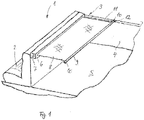
- a motor vehicle in the form of a passenger car has according to Fig. 1 a vehicle interior 1, which is provided with a rear-side cargo space.
- the rear-side cargo space has a load compartment floor 5, which is bounded to opposite longitudinal sides by a respective load compartment side wall 4. Seen in the normal direction of travel forward, the cargo space is limited by a backrest arrangement of a rear bench seat 2.
- the load compartment is assigned a protective device 3, which is described below with reference to Fig. 1 to 11 will be described in more detail.
- the protective device 3 has a dimensionally stable cassette housing 6, which is arranged fixed to the vehicle behind the backrest arrangement of the rear bench seat 2 and extends in the vehicle transverse direction across the width of the cargo space.
- a winding shaft 7 is rotatably mounted, on which a flexible sheet 8 in the form of a cover is held up and unwound.
- the flexible sheet 8 is pulled out through a longitudinal slot in the cassette housing 6 to a rear of the vehicle and pulled back through this longitudinal slot.
- the winding shaft 7 is permanently torqued by a return spring in the winding.
- the flexible sheet 8 has at its front end region in the extension direction a dimensionally stable guide profile 9, which extends over an entire width of the flexible sheet 8 and is guided parallelverlagerbar with its opposite Stirnend Schemeen 10 in load space fixed guide tracks 11 in the form of guide rails.
- the guide tracks 11 extend approximately at the level of the longitudinal slot of the cassette housing 6 along the respective loading space side wall 4 in the vehicle longitudinal direction to the rear, wherein each of the two guide tracks 11 is guided at least substantially parallel to the load compartment floor 5 in the opposite Laderaum cleansingwanditch 4.
- the two guide tracks 11 are integrated into the loading space side walls 4 and firmly connected to support structure parts of the vehicle body.
- the two guide tracks 11 extend over the length of the loading space.
- a driver 12 is guided in each case, which is movable over an unillustrated drive system along the respective guide track 11 in the vehicle longitudinal direction to the front and in the vehicle longitudinal direction to the rear.
- Both drivers 12 are by means of Drive system synchronously to each other in the opposite guide tracks 11 movable.
- the drive system has an electric motor and flexible drive transmission means in the form of thread pitch cables or in the form of flexible racks, which are driven synchronously and in opposite directions by means of a suitable transmission via the electric motor.
- the drive transmission means are connected to the respective driver 12, so that a displacement of the drive transmission means inevitably causes the desired displacement of the driver 12 in the guide tracks 11.
- the basic traversing function as well as the receiving and driving as well as release function of the driver in the vehicle longitudinal direction correspond in all embodiments according to the Fig. 1 to 11 in the EP 1 084 907 A2 described functions.
- the drivers 12 take the opposing front end regions 10 by means of a respective force-limited holding device.
- the force-limited effective holding device is arranged on the respective driver 12.
- the force-limited effective holding device has two leaf spring legs 13 which are firmly clamped on one side on the driver 12 and toward the cassette housing 6, ie the winding shaft 7, are open to allow a force-limited recording or releasing the respective front end portion 10 of the guide profile 9.
- a coupling member 14 to 16 is provided, which has a mushroom head 14 with a rectangular outer contour, a parallel to a central longitudinal axis of the guide profile 9 extended support pin 15 and an eccentric plate 16 from which the support pin 15 protrudes.
- the eccentric plate 16 is rotatably connected to the guide profile 9.
- the support pin 15 is fixedly arranged on the eccentric plate 16 and the mushroom head 14 is frontally attached to a projecting away from the eccentric plate 16, free end portion of the support pin 15.
- the mushroom head 14, the support pin 15 and the eccentric plate 16 are integrally formed with each other.
- the eccentric plate 16 is attached to the front side of the guide profile 9.
- the mushroom head 14, as shown by the Fig. 4 can be seen, an outer contour, which is provided with two wider edge legs and approximately at right angles thereto with two narrower edge legs.
- the two shorter edge legs form a broad attack surface when the mushroom head 14 according to Fig. 4 oriented upright.
- the two longer edge legs form a narrow attack surface of the mushroom head 14 when the mushroom head 14 is rotated by 90 °.
- the narrow attack surface is designed such that the mushroom head 14 in this narrower orientation, ie in the horizontal orientation of its wider attack surface, between the opposite leaf spring legs 13 of the force-limited effective holding device can slide freely without the leaf spring legs 13 cause a positive retention.
- the leaf spring legs 13 In the upright orientation, in which the broad attack surface of the mushroom head 14 according to Fig. 4 is effective, the leaf spring legs 13 form a force-limited, positive retention.
- the force limitation is effected by the elastic bending force of the leaf spring legs 13.
- the guide profile 9 is according to Fig. 4 aligned so that the eccentric plate 16 is extended forward relative to the rearwardly extended sheet 8 and the support pin 15 of each coupling member is spaced apart in parallel from the central longitudinal axis of the guide profile 9.
- the mushroom head 14 of the coupling member is aligned upright and locked between the leaf spring legs 13 of the force-limited effective holding device of the respective driver 12.
- Fig. 5 to 11 are in accordance with the protection device 3 in the same way Fig. 1 can be used as the previously described guide profile 9. functionally identical parts or sections are therefore provided with the same reference numerals with the addition of the letters a or b.
- the force-limited effective holding devices which are effective between the movable in the load-retaining guide tracks 11 drivers 12a, 12b and attached to the guide profile 9a coupling members of the opposite Stirnend Schemee 10a, 10b, the Stirnend Schemeen 10a, 10b of the respective guide profile 9a, 9b assigned are.
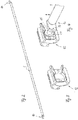
- Fig. 5 to 7 has the respective driver 12a, which is movable in the respective guide track 11, a projecting in the vehicle transverse direction inwardly Mit supportivezapfen, which is in positive contact with the corresponding force-limited holding device on the coupling member of the respective front end portion 10a.
- the force-limited effective holding device is formed by a force-limited rotatable holding leg 17 which is rotatably mounted limited to a rotational axis D at the fixed to the guide profile 9a Stirnend Scheme 10a.
- the holding leg 17 forms a pawl, which is positioned in the region of an upper side of the front end region 10a.
- the retaining leg 17 cooperates with a counter-support 18, which forms a guide surface for the driving pin of the driver 12a.
- the driving pin is held eccentrically offset from a central longitudinal axis of the guide profile 9a on the counter-support 18 and the holding leg 17.
- the retaining leg 17 may be additionally spring-loaded in the closing direction.
- the spring loading by a leg spring which is coaxial with the axis of rotation D between the front end portion 10a of the guide profile 9a and the holding leg 17 is effective.
- the axis of rotation D is parallel, but positioned eccentrically to the central longitudinal axis of the guide profile 9a.
- the driving pins of the drivers 12a take up the respective front end region 10a of the guide profile 9a Fig. 6 With.
- the holding leg 17 can according to Fig. 7 to escape upwards, whereby the driving pin of the driver 12 a between the counter-support 18 and the holding leg 17 can escape from the respective front end portion 10 a.
- the sheet 8 engages the guide profile 9a in the illustrations according to 6 and 7 on the right side of the plane of the drawing, so that the return force acting on the fabric 8 assists the release of the respective driver pin 12a of the drivers.
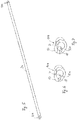
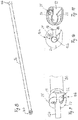
- the respective force-limited holding device is also associated with the respective coupling member of the respective front end region 10b of the guide profile 9b.
- the two drivers which are movable in the load-retaining guide tracks 11, are provided only with simple driving pins 12b, which protrude in the vehicle transverse direction towards the center of the cargo space inwards.
- Each coupling member on the opposite end faces 10b of the guide profile 9b has a support portion 19 fixedly connected to the guide profile 9b and a jaw portion 20 rotatably mounted on the support portion 19 about a rotation axis 21 and provided with the force-limited holding means.
- the force-limited effective holding device is formed by a leaf spring 22 which defines an open towards one side locking receptacle for the driving pin of the driver 12b (see Fig. 9 to 11 ). Also, the claw portion 22 is analogous to the opening of the leaf spring 22 open to one side.
- the axis of rotation 21 is positioned axially parallel to a central longitudinal axis of the guide profile 9b above the central longitudinal axis of the guide profile 9b on the holding section 19.
- the leaf spring 22 is according to Fig. 11 positioned in the rotatable jaw portion 20 and rotatable together with this.
- the sheet 8 exerts on the guide profile 9b due to the return force of the return spring of the winding shaft from a tensile load in a direction which is opposite to the opening of the leaf spring 22 and the claw portion 20 and thus in the drawing plane according to the 10 and 11 to the left.
- the claw portion 20 rotates together with the leaf spring 22, whereby the driving pin of the respective driver 12b can be released from the claw portion 20.
Landscapes
- Engineering & Computer Science (AREA)
- Mechanical Engineering (AREA)
- Vehicle Step Arrangements And Article Storage (AREA)
- Fittings On The Vehicle Exterior For Carrying Loads, And Devices For Holding Or Mounting Articles (AREA)
Applications Claiming Priority (1)
| Application Number | Priority Date | Filing Date | Title |
|---|---|---|---|
| DE102016215599.7A DE102016215599B3 (de) | 2016-08-19 | 2016-08-19 | Schutzvorrichtung für einen Fahrzeuginnenraum |
Publications (2)
| Publication Number | Publication Date |
|---|---|
| EP3284635A1 true EP3284635A1 (fr) | 2018-02-21 |
| EP3284635B1 EP3284635B1 (fr) | 2019-03-06 |
Family
ID=59295692
Family Applications (1)
| Application Number | Title | Priority Date | Filing Date |
|---|---|---|---|
| EP17180976.7A Active EP3284635B1 (fr) | 2016-08-19 | 2017-07-12 | Dispositif de protection d'habitacle de véhicule |
Country Status (4)
| Country | Link |
|---|---|
| US (1) | US10457219B2 (fr) |
| EP (1) | EP3284635B1 (fr) |
| CN (1) | CN107757501B (fr) |
| DE (1) | DE102016215599B3 (fr) |
Families Citing this family (5)
| Publication number | Priority date | Publication date | Assignee | Title |
|---|---|---|---|---|
| JP6793545B2 (ja) * | 2016-12-28 | 2020-12-02 | 矢崎総業株式会社 | 巻取装置及び配索構造 |
| KR102542953B1 (ko) | 2018-04-12 | 2023-06-13 | 현대자동차주식회사 | 차량의 러기지룸 스크린 장치 |
| FR3088270B1 (fr) * | 2018-11-08 | 2020-12-11 | Treves Products Services & Innovation | Systeme de recouvrement d’un compartiment a bagages de vehicule automobile |
| FR3096631B1 (fr) * | 2019-05-31 | 2021-11-12 | Inteva Products France Sas | Cache-bagages motorisé pour vehicule |
| KR102906465B1 (ko) * | 2023-11-03 | 2025-12-31 | 주식회사 서연이화 | 카고 스크린의 하우징 커버 |
Citations (5)
| Publication number | Priority date | Publication date | Assignee | Title |
|---|---|---|---|---|
| EP1084907A2 (fr) * | 1999-09-20 | 2001-03-21 | BOS GmbH & Co. KG | Dispositif de protection pour l'habitacle d'un véhicule |
| JP2003127777A (ja) * | 2001-10-23 | 2003-05-08 | Kasai Kogyo Co Ltd | 車両用トノカバー装置 |
| JP2007153128A (ja) * | 2005-12-05 | 2007-06-21 | Mazda Motor Corp | 車体後部構造 |
| DE102009036606B3 (de) * | 2009-07-30 | 2010-08-12 | Bos Gmbh & Co. Kg | Schutzvorrichtung für einen Fahrzeuginnenraum |
| DE102009023723A1 (de) * | 2009-06-03 | 2010-12-09 | Bayerische Motoren Werke Aktiengesellschaft | Kraftfahrzeug |
Family Cites Families (22)
| Publication number | Priority date | Publication date | Assignee | Title |
|---|---|---|---|---|
| US5860466A (en) * | 1996-02-02 | 1999-01-19 | Kao; Nien Tsu Tim | Windshield shelter |
| US6003920A (en) * | 1997-06-17 | 1999-12-21 | Peter Butz Gmbh & Co. | Cargo-space cover for motor vehicle |
| DE10102627A1 (de) * | 2001-01-18 | 2002-08-01 | Bos Gmbh | Abdeckvorrichtung für einen Laderaum eines Kraftfahrzeugs |
| DE10356911B3 (de) * | 2003-12-02 | 2005-01-20 | Bos Gmbh & Co. Kg | Laderaumschutzvorrichtung für ein Kraftfahrzeug |
| DE102004008874A1 (de) * | 2004-02-18 | 2005-09-08 | Bos Gmbh & Co. Kg | Funktionseinheit für einen Fahrzeuginnenraum |
| DE102004029042A1 (de) * | 2004-06-08 | 2005-12-29 | Bos Gmbh & Co. Kg | Schutzvorrichtung für einen Fahrzeuginnenraum |
| DE102005033819A1 (de) * | 2005-07-11 | 2007-01-25 | Bos Gmbh & Co. Kg | Laderaumschutzvorrichtung mit wenigstens einer Wickelwelle |
| DE102005048207B3 (de) * | 2005-10-07 | 2006-11-23 | Webasto Ag | Rolloanordnung für ein Kraftfahrzeug |
| DE102005055625C5 (de) * | 2005-11-22 | 2010-05-20 | Bayerische Motoren Werke Aktiengesellschaft | Laderaumabdeckung für ein Fahrzeug |
| EP1787864B1 (fr) | 2005-11-22 | 2009-03-25 | Mazda Motor Corporation | Structure arrière de véhicule |
| JP4247751B2 (ja) * | 2006-08-10 | 2009-04-02 | トヨタ紡織株式会社 | サンシェード装置 |
| US7673921B2 (en) * | 2007-01-24 | 2010-03-09 | Mazda Motor Corporation | Tonneau cover device of vehicle |
| DE202007016329U1 (de) * | 2007-09-14 | 2008-02-14 | Bos Gmbh & Co. Kg | Schutzvorrichtung für einen Fahrzeuginnenraum |
| DE102007057074A1 (de) * | 2007-11-23 | 2009-06-04 | Bos Gmbh & Co. Kg | Rollosystem |
| KR101220052B1 (ko) * | 2010-10-13 | 2013-01-21 | 현대자동차주식회사 | 러기지 룸 스크린의 오토 리턴 구조 |
| TWM428992U (en) * | 2011-12-08 | 2012-05-11 | Macauto Ind Co Ltd | Track type sunshade device |
| US20130153160A1 (en) * | 2011-11-18 | 2013-06-20 | Macauto Industrial Co., Ltd. | Sunshade assembly |
| DE102012221585B4 (de) * | 2012-11-26 | 2016-11-24 | Bos Gmbh & Co. Kg | Rückhaltevorrichtung für einen Fahrzeuginnenraum |
| DE102012221586B8 (de) * | 2012-11-26 | 2014-08-14 | Bos Gmbh & Co. Kg | Schutzvorrichtung für einen Raumabschnitt eines Kraftfahrzeugs |
| DE102013210191B4 (de) * | 2013-05-31 | 2017-10-19 | Bos Gmbh & Co. Kg | Schutzvorrichtung für einen Fahrzeuginnenraum |
| DE102013022154A1 (de) * | 2013-12-30 | 2015-07-02 | Volkswagen Aktiengesellschaft | Abdeckvorrichtung |
| DE102015118775B4 (de) * | 2015-11-03 | 2019-02-21 | Macauto Industrial Co., Ltd. | Laderaumabdeckung |
-
2016
- 2016-08-19 DE DE102016215599.7A patent/DE102016215599B3/de not_active Expired - Fee Related
-
2017
- 2017-07-12 EP EP17180976.7A patent/EP3284635B1/fr active Active
- 2017-07-31 US US15/664,684 patent/US10457219B2/en active Active
- 2017-08-18 CN CN201710711500.XA patent/CN107757501B/zh active Active
Patent Citations (5)
| Publication number | Priority date | Publication date | Assignee | Title |
|---|---|---|---|---|
| EP1084907A2 (fr) * | 1999-09-20 | 2001-03-21 | BOS GmbH & Co. KG | Dispositif de protection pour l'habitacle d'un véhicule |
| JP2003127777A (ja) * | 2001-10-23 | 2003-05-08 | Kasai Kogyo Co Ltd | 車両用トノカバー装置 |
| JP2007153128A (ja) * | 2005-12-05 | 2007-06-21 | Mazda Motor Corp | 車体後部構造 |
| DE102009023723A1 (de) * | 2009-06-03 | 2010-12-09 | Bayerische Motoren Werke Aktiengesellschaft | Kraftfahrzeug |
| DE102009036606B3 (de) * | 2009-07-30 | 2010-08-12 | Bos Gmbh & Co. Kg | Schutzvorrichtung für einen Fahrzeuginnenraum |
Also Published As
| Publication number | Publication date |
|---|---|
| CN107757501B (zh) | 2022-04-01 |
| EP3284635B1 (fr) | 2019-03-06 |
| US10457219B2 (en) | 2019-10-29 |
| DE102016215599B3 (de) | 2017-07-27 |
| CN107757501A (zh) | 2018-03-06 |
| US20180050643A1 (en) | 2018-02-22 |
Similar Documents
| Publication | Publication Date | Title |
|---|---|---|
| EP3284635B1 (fr) | Dispositif de protection d'habitacle de véhicule | |
| DE102007047758B4 (de) | Schutzvorrichtung für einen Fahrzeuginnenraum | |
| DE102009024292B4 (de) | Gurtaufroller für einen Sicherheitsgurt eines Kraftfahrzeuges | |
| WO2016037869A1 (fr) | Dispositif de sécurisation de charge | |
| WO2006010484A1 (fr) | Element pour presenter une ceinture de securite a un passager de vehicule | |
| DE102012004999A1 (de) | Kraftfahrzeuganhängevorrichtung | |
| DE102013210191B4 (de) | Schutzvorrichtung für einen Fahrzeuginnenraum | |
| DE102011079924B4 (de) | Schutzvorrichtung für einen Fahrzeuginnenraum | |
| EP1122121B1 (fr) | Dispositif à conteneur de transport pour le montage dans un véhicule automobile par exemple un dispositif à évidement de chargement | |
| EP0492035A1 (fr) | Attelage de remorque, en particulier pour véhicules automobiles | |
| DE102009036605B3 (de) | Haltevorrichtung für ein Kassettengehäuse | |
| EP2922728A1 (fr) | Dispositif de protection destiné à l'habitacle d'un véhicule et mécanisme de levage pour ledit dispositif | |
| DE2308895C3 (de) | Mit Sicherheitsgurten ausgerüsteter Fahrzeugsitz | |
| DE102018201268B4 (de) | Schutzvorrichtung für einen Kraftfahrzeuginnenraum | |
| WO2017144280A1 (fr) | Dispositif de fixation pour porte-charge | |
| DE19836849C1 (de) | Dachanordnung | |
| DE10046142B4 (de) | Vorrichtung zur Festlegung eines Endbereiches einer Fahrzeug- Sicherheitseinrichtung an einem fahrzeugseitigen Befestigungspunkt sowie zur Spannung des Endbereichs der Fahrzeug-Sicherheitseinrichtung relativ zu dem Befestigungspunkt | |
| EP3440293B1 (fr) | Système de cales de fermeture pour accoupler de façon amovible une porte de véhicule à un élément structurel d'une carrosserie de véhicule | |
| DE602006000342T2 (de) | Sicherheitsgurt für ein Kraftfahrzeug und dazugehöriger Sitz | |
| WO2017016795A1 (fr) | Dispositif destiné au réglage réversible d'une colonne de direction d'un véhicule à moteur d'une position d'utilisation à une position d'accès aisé (easy-entry), et système de direction | |
| DE19818583C1 (de) | Kraftfahrzeug mit mindestens einem zwischen Fahrgastraum und Laderaum anbringbaren Rollo | |
| DE102013221077B4 (de) | Haltevorrichtung für Sicherheitsgurt | |
| DE102019112908A1 (de) | Fahrzeugkomponente mit wenigstens einer Befestigungsanordnung für wenigstens ein Scanmodul | |
| DE102019208215A1 (de) | Abdeckvorrichtung für einen Laderaum eines Kraftfahrzeugs | |
| DE102012005652B4 (de) | Kopfstütze |
Legal Events
| Date | Code | Title | Description |
|---|---|---|---|
| PUAI | Public reference made under article 153(3) epc to a published international application that has entered the european phase |
Free format text: ORIGINAL CODE: 0009012 |
|
| STAA | Information on the status of an ep patent application or granted ep patent |
Free format text: STATUS: THE APPLICATION HAS BEEN PUBLISHED |
|
| AK | Designated contracting states |
Kind code of ref document: A1 Designated state(s): AL AT BE BG CH CY CZ DE DK EE ES FI FR GB GR HR HU IE IS IT LI LT LU LV MC MK MT NL NO PL PT RO RS SE SI SK SM TR |
|
| AX | Request for extension of the european patent |
Extension state: BA ME |
|
| STAA | Information on the status of an ep patent application or granted ep patent |
Free format text: STATUS: REQUEST FOR EXAMINATION WAS MADE |
|
| 17P | Request for examination filed |
Effective date: 20180814 |
|
| RBV | Designated contracting states (corrected) |
Designated state(s): AL AT BE BG CH CY CZ DE DK EE ES FI FR GB GR HR HU IE IS IT LI LT LU LV MC MK MT NL NO PL PT RO RS SE SI SK SM TR |
|
| GRAP | Despatch of communication of intention to grant a patent |
Free format text: ORIGINAL CODE: EPIDOSNIGR1 |
|
| STAA | Information on the status of an ep patent application or granted ep patent |
Free format text: STATUS: GRANT OF PATENT IS INTENDED |
|
| INTG | Intention to grant announced |
Effective date: 20181010 |
|
| GRAS | Grant fee paid |
Free format text: ORIGINAL CODE: EPIDOSNIGR3 |
|
| GRAA | (expected) grant |
Free format text: ORIGINAL CODE: 0009210 |
|
| STAA | Information on the status of an ep patent application or granted ep patent |
Free format text: STATUS: THE PATENT HAS BEEN GRANTED |
|
| AK | Designated contracting states |
Kind code of ref document: B1 Designated state(s): AL AT BE BG CH CY CZ DE DK EE ES FI FR GB GR HR HU IE IS IT LI LT LU LV MC MK MT NL NO PL PT RO RS SE SI SK SM TR |
|
| REG | Reference to a national code |
Ref country code: GB Ref legal event code: FG4D Free format text: NOT ENGLISH |
|
| REG | Reference to a national code |
Ref country code: CH Ref legal event code: EP Ref country code: AT Ref legal event code: REF Ref document number: 1104095 Country of ref document: AT Kind code of ref document: T Effective date: 20190315 |
|
| REG | Reference to a national code |
Ref country code: DE Ref legal event code: R096 Ref document number: 502017000875 Country of ref document: DE |
|
| REG | Reference to a national code |
Ref country code: IE Ref legal event code: FG4D Free format text: LANGUAGE OF EP DOCUMENT: GERMAN |
|
| REG | Reference to a national code |
Ref country code: NL Ref legal event code: MP Effective date: 20190306 |
|
| REG | Reference to a national code |
Ref country code: LT Ref legal event code: MG4D |
|
| PG25 | Lapsed in a contracting state [announced via postgrant information from national office to epo] |
Ref country code: SE Free format text: LAPSE BECAUSE OF FAILURE TO SUBMIT A TRANSLATION OF THE DESCRIPTION OR TO PAY THE FEE WITHIN THE PRESCRIBED TIME-LIMIT Effective date: 20190306 Ref country code: FI Free format text: LAPSE BECAUSE OF FAILURE TO SUBMIT A TRANSLATION OF THE DESCRIPTION OR TO PAY THE FEE WITHIN THE PRESCRIBED TIME-LIMIT Effective date: 20190306 Ref country code: LT Free format text: LAPSE BECAUSE OF FAILURE TO SUBMIT A TRANSLATION OF THE DESCRIPTION OR TO PAY THE FEE WITHIN THE PRESCRIBED TIME-LIMIT Effective date: 20190306 Ref country code: NO Free format text: LAPSE BECAUSE OF FAILURE TO SUBMIT A TRANSLATION OF THE DESCRIPTION OR TO PAY THE FEE WITHIN THE PRESCRIBED TIME-LIMIT Effective date: 20190606 |
|
| PG25 | Lapsed in a contracting state [announced via postgrant information from national office to epo] |
Ref country code: BG Free format text: LAPSE BECAUSE OF FAILURE TO SUBMIT A TRANSLATION OF THE DESCRIPTION OR TO PAY THE FEE WITHIN THE PRESCRIBED TIME-LIMIT Effective date: 20190606 Ref country code: GR Free format text: LAPSE BECAUSE OF FAILURE TO SUBMIT A TRANSLATION OF THE DESCRIPTION OR TO PAY THE FEE WITHIN THE PRESCRIBED TIME-LIMIT Effective date: 20190607 Ref country code: LV Free format text: LAPSE BECAUSE OF FAILURE TO SUBMIT A TRANSLATION OF THE DESCRIPTION OR TO PAY THE FEE WITHIN THE PRESCRIBED TIME-LIMIT Effective date: 20190306 Ref country code: HR Free format text: LAPSE BECAUSE OF FAILURE TO SUBMIT A TRANSLATION OF THE DESCRIPTION OR TO PAY THE FEE WITHIN THE PRESCRIBED TIME-LIMIT Effective date: 20190306 Ref country code: NL Free format text: LAPSE BECAUSE OF FAILURE TO SUBMIT A TRANSLATION OF THE DESCRIPTION OR TO PAY THE FEE WITHIN THE PRESCRIBED TIME-LIMIT Effective date: 20190306 Ref country code: RS Free format text: LAPSE BECAUSE OF FAILURE TO SUBMIT A TRANSLATION OF THE DESCRIPTION OR TO PAY THE FEE WITHIN THE PRESCRIBED TIME-LIMIT Effective date: 20190306 |
|
| PG25 | Lapsed in a contracting state [announced via postgrant information from national office to epo] |
Ref country code: AL Free format text: LAPSE BECAUSE OF FAILURE TO SUBMIT A TRANSLATION OF THE DESCRIPTION OR TO PAY THE FEE WITHIN THE PRESCRIBED TIME-LIMIT Effective date: 20190306 Ref country code: PT Free format text: LAPSE BECAUSE OF FAILURE TO SUBMIT A TRANSLATION OF THE DESCRIPTION OR TO PAY THE FEE WITHIN THE PRESCRIBED TIME-LIMIT Effective date: 20190706 Ref country code: RO Free format text: LAPSE BECAUSE OF FAILURE TO SUBMIT A TRANSLATION OF THE DESCRIPTION OR TO PAY THE FEE WITHIN THE PRESCRIBED TIME-LIMIT Effective date: 20190306 Ref country code: CZ Free format text: LAPSE BECAUSE OF FAILURE TO SUBMIT A TRANSLATION OF THE DESCRIPTION OR TO PAY THE FEE WITHIN THE PRESCRIBED TIME-LIMIT Effective date: 20190306 Ref country code: ES Free format text: LAPSE BECAUSE OF FAILURE TO SUBMIT A TRANSLATION OF THE DESCRIPTION OR TO PAY THE FEE WITHIN THE PRESCRIBED TIME-LIMIT Effective date: 20190306 Ref country code: EE Free format text: LAPSE BECAUSE OF FAILURE TO SUBMIT A TRANSLATION OF THE DESCRIPTION OR TO PAY THE FEE WITHIN THE PRESCRIBED TIME-LIMIT Effective date: 20190306 Ref country code: SK Free format text: LAPSE BECAUSE OF FAILURE TO SUBMIT A TRANSLATION OF THE DESCRIPTION OR TO PAY THE FEE WITHIN THE PRESCRIBED TIME-LIMIT Effective date: 20190306 Ref country code: IT Free format text: LAPSE BECAUSE OF FAILURE TO SUBMIT A TRANSLATION OF THE DESCRIPTION OR TO PAY THE FEE WITHIN THE PRESCRIBED TIME-LIMIT Effective date: 20190306 |
|
| PG25 | Lapsed in a contracting state [announced via postgrant information from national office to epo] |
Ref country code: PL Free format text: LAPSE BECAUSE OF FAILURE TO SUBMIT A TRANSLATION OF THE DESCRIPTION OR TO PAY THE FEE WITHIN THE PRESCRIBED TIME-LIMIT Effective date: 20190306 Ref country code: SM Free format text: LAPSE BECAUSE OF FAILURE TO SUBMIT A TRANSLATION OF THE DESCRIPTION OR TO PAY THE FEE WITHIN THE PRESCRIBED TIME-LIMIT Effective date: 20190306 |
|
| REG | Reference to a national code |
Ref country code: DE Ref legal event code: R097 Ref document number: 502017000875 Country of ref document: DE |
|
| PG25 | Lapsed in a contracting state [announced via postgrant information from national office to epo] |
Ref country code: IS Free format text: LAPSE BECAUSE OF FAILURE TO SUBMIT A TRANSLATION OF THE DESCRIPTION OR TO PAY THE FEE WITHIN THE PRESCRIBED TIME-LIMIT Effective date: 20190706 |
|
| PLBE | No opposition filed within time limit |
Free format text: ORIGINAL CODE: 0009261 |
|
| STAA | Information on the status of an ep patent application or granted ep patent |
Free format text: STATUS: NO OPPOSITION FILED WITHIN TIME LIMIT |
|
| PG25 | Lapsed in a contracting state [announced via postgrant information from national office to epo] |
Ref country code: DK Free format text: LAPSE BECAUSE OF FAILURE TO SUBMIT A TRANSLATION OF THE DESCRIPTION OR TO PAY THE FEE WITHIN THE PRESCRIBED TIME-LIMIT Effective date: 20190306 |
|
| 26N | No opposition filed |
Effective date: 20191209 |
|
| PG25 | Lapsed in a contracting state [announced via postgrant information from national office to epo] |
Ref country code: MC Free format text: LAPSE BECAUSE OF FAILURE TO SUBMIT A TRANSLATION OF THE DESCRIPTION OR TO PAY THE FEE WITHIN THE PRESCRIBED TIME-LIMIT Effective date: 20190306 Ref country code: SI Free format text: LAPSE BECAUSE OF FAILURE TO SUBMIT A TRANSLATION OF THE DESCRIPTION OR TO PAY THE FEE WITHIN THE PRESCRIBED TIME-LIMIT Effective date: 20190306 |
|
| PG25 | Lapsed in a contracting state [announced via postgrant information from national office to epo] |
Ref country code: TR Free format text: LAPSE BECAUSE OF FAILURE TO SUBMIT A TRANSLATION OF THE DESCRIPTION OR TO PAY THE FEE WITHIN THE PRESCRIBED TIME-LIMIT Effective date: 20190306 |
|
| REG | Reference to a national code |
Ref country code: BE Ref legal event code: MM Effective date: 20190731 |
|
| PG25 | Lapsed in a contracting state [announced via postgrant information from national office to epo] |
Ref country code: BE Free format text: LAPSE BECAUSE OF NON-PAYMENT OF DUE FEES Effective date: 20190731 Ref country code: LU Free format text: LAPSE BECAUSE OF NON-PAYMENT OF DUE FEES Effective date: 20190712 |
|
| PG25 | Lapsed in a contracting state [announced via postgrant information from national office to epo] |
Ref country code: FR Free format text: LAPSE BECAUSE OF NON-PAYMENT OF DUE FEES Effective date: 20190731 |
|
| PG25 | Lapsed in a contracting state [announced via postgrant information from national office to epo] |
Ref country code: IE Free format text: LAPSE BECAUSE OF NON-PAYMENT OF DUE FEES Effective date: 20190712 |
|
| REG | Reference to a national code |
Ref country code: CH Ref legal event code: PL |
|
| PG25 | Lapsed in a contracting state [announced via postgrant information from national office to epo] |
Ref country code: CH Free format text: LAPSE BECAUSE OF NON-PAYMENT OF DUE FEES Effective date: 20200731 Ref country code: LI Free format text: LAPSE BECAUSE OF NON-PAYMENT OF DUE FEES Effective date: 20200731 |
|
| PG25 | Lapsed in a contracting state [announced via postgrant information from national office to epo] |
Ref country code: CY Free format text: LAPSE BECAUSE OF FAILURE TO SUBMIT A TRANSLATION OF THE DESCRIPTION OR TO PAY THE FEE WITHIN THE PRESCRIBED TIME-LIMIT Effective date: 20190306 |
|
| PG25 | Lapsed in a contracting state [announced via postgrant information from national office to epo] |
Ref country code: MT Free format text: LAPSE BECAUSE OF FAILURE TO SUBMIT A TRANSLATION OF THE DESCRIPTION OR TO PAY THE FEE WITHIN THE PRESCRIBED TIME-LIMIT Effective date: 20190306 Ref country code: HU Free format text: LAPSE BECAUSE OF FAILURE TO SUBMIT A TRANSLATION OF THE DESCRIPTION OR TO PAY THE FEE WITHIN THE PRESCRIBED TIME-LIMIT; INVALID AB INITIO Effective date: 20170712 |
|
| GBPC | Gb: european patent ceased through non-payment of renewal fee |
Effective date: 20210712 |
|
| PG25 | Lapsed in a contracting state [announced via postgrant information from national office to epo] |
Ref country code: GB Free format text: LAPSE BECAUSE OF NON-PAYMENT OF DUE FEES Effective date: 20210712 |
|
| PG25 | Lapsed in a contracting state [announced via postgrant information from national office to epo] |
Ref country code: MK Free format text: LAPSE BECAUSE OF FAILURE TO SUBMIT A TRANSLATION OF THE DESCRIPTION OR TO PAY THE FEE WITHIN THE PRESCRIBED TIME-LIMIT Effective date: 20190306 |
|
| REG | Reference to a national code |
Ref country code: AT Ref legal event code: MM01 Ref document number: 1104095 Country of ref document: AT Kind code of ref document: T Effective date: 20220712 |
|
| PG25 | Lapsed in a contracting state [announced via postgrant information from national office to epo] |
Ref country code: AT Free format text: LAPSE BECAUSE OF NON-PAYMENT OF DUE FEES Effective date: 20220712 |
|
| PGFP | Annual fee paid to national office [announced via postgrant information from national office to epo] |
Ref country code: DE Payment date: 20250723 Year of fee payment: 9 |